1
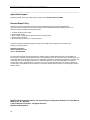
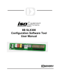
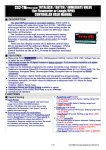
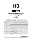
®
MAQ 20
Industrial Data Acquisition
and Control System
Configuration Software Tool
User Manual
MAQ®20 Configuration Software Tool User Manual
®
MAQ 20 Industrial Data Acquisition and Control System Configuration Software Tool User Manual
MA1037 Rev. B – May 2012
© 2012 Dataforth Corporation. All Rights Reserved.
ISO9001:2008-Registered QMS
The information in this manual has been checked carefully and is believed to be accurate; however,
Dataforth assumes no responsibility for possible inaccuracies or omissions. Specifications are subject to
change without notice.
The information, tables, diagrams, and photographs contained herein are the property of Dataforth
Corporation. No part of this manual may be reproduced or distributed by any means, electronic,
mechanical, or otherwise, for any purpose other than the purchaser’s personal use, without the express
written consent of Dataforth Corporation.
®
MAQ 20 is a registered trademark of Dataforth Corporation.
ii
MAQ®20 Configuration Software Tool User Manual
Table of Contents
1.0 MAQ®20 Communication Setup
1.1
Quick Setup ................................................................................................................................... 1
1.2
MAQ 20 Communication Setup & Connection ........................................................................... 1
®
2.0 MAQ®20 Configuration Software Tool Panel
2.1
Registration Tab ............................................................................................................................ 3
2.2
Module Data Tab ........................................................................................................................... 4
3.0 Configuring the MAQ®20 Communications Module
3.1
Communication Settings ............................................................................................................... 5
3.2
Real Time Clock ............................................................................................................................ 5
3.3
Logging Settings ........................................................................................................................... 5
4.0 Configuring the MAQ®20 Volt/Millivolt Input Module
4.1
Input Channel Configuration ......................................................................................................... 6
4.2
Analog Input Readings .............................................................................................................. 6
4.3
Alarm Configuration for Input Channels ........................................................................................ 7
4.4
Reset Input Readings .................................................................................................................... 7
®
5.0 Configuring the MAQ 20 Thermocouple Input Module
5.1
TC Channel Configuration ............................................................................................................. 8
5.2
TC Input Readings ........................................................................................................................ 8
5.3
Alarm Configuration for TC Input Channels .................................................................................. 9
5.4
Reset TC Input Readings .............................................................................................................. 9
6.0 Configuring the MAQ®20 Voltage Output Module
6.1
Voltage Output and Range Values ............................................................................................. 10
6.2
Load Buffer Data Values ............................................................................................................. 10
6.3
Voltage Output Default Values .................................................................................................... 11
7.0 Configuring the MAQ®20 Discrete Voltage Output Module
7.1
Discrete I/O Configuration ........................................................................................................... 12
7.2
Discrete I/O Special Function Alarms ......................................................................................... 13
7.3
Special Function Panels ............................................................................................................. 14
7.3.1 Pulse / Frequency Counter Function ................................................................................. 14
iii
MAQ®20 Configuration Software Tool User Manual
7.3.2 Pulse / Frequency Counter with De-bounce Function ....................................................... 14
7.3.3 Waveform Measurement Function ..................................................................................... 14
7.3.4 Time Between Events Function ......................................................................................... 14
7.3.5 Frequency Generator Function .......................................................................................... 15
7.3.6 PWM Generator Function .................................................................................................. 15
7.3.7 One-Shot Pulse Generator Function .................................................................................. 15
iv
MAQ®20 Configuration Software Tool User Manual
About Dataforth Corporation
“Our passion at Dataforth Corporation is designing, manufacturing, and marketing the best possible signal
conditioning, data acquisition, and data communication products. Our mission is to set new standards of
product quality, performance, and customer service.” Dataforth Corporation, with more than a quarter
®
century of experience, is the worldwide leader in Instrument Class Industrial Electronics – rugged, high
performance signal conditioning, data acquisition, and data communication products that play a vital role
in maintaining the integrity of industrial automation, data acquisition, and quality assurance systems. Our
products directly connect to most industrial sensors and protect valuable measurement and control
signals and equipment from the dangerous and degrading effects of noise, transient power surges,
internal ground loops, and other hazards present in industrial environments.
Dataforth spans the globe with more than 50 International Distributors and US Representative
Companies. Our customers benefit from a team of over 130 sales people highly trained in the application
of precision products for industrial markets. In addition, we have a team of application engineers in our
Tucson factory ready to solve any in-depth application questions. Upon receipt of an RFQ or order, our
Customer Service Department provides fast one-day delivery information turnaround. We maintain an
ample inventory that allows small quantity orders to be shipped from stock.
Contacting Dataforth Corporation
Contact Method
E-Mail:
Technical Support
Website:
Phone:
Fax:
Mail:
Contact Information
[email protected]
www.dataforth.com
520-741-1404 and toll free 800-444-7644
520-741-0762
Dataforth Corporation
3331 E. Hemisphere Loop
Tucson, AZ 85706
Errata Sheets
Refer to the Technical Support area of Dataforth’s website (www.dataforth.com) for any errata information
on this product.
v
MAQ®20 Software Configuration User Guide
1.0
MAQ®20 Communication Setup
1.1
Quick Setup
1. Download the Configuration Software Tool from the Dataforth website, www.dataforth.com and
follow the installation procedure. If the system will be used with a USB connection to the host
PC, the USB Driver must be installed prior to connecting the system to the computer. Download
the driver from www.dataforth.com and follow the installation instructions.
®
2. Start the MAQ 20 Configuration Software Tool program by double-clicking the icon MAQ20
Config SW Tool shortcut on the desktop. Alternately there is a MAQ20 Config SW Tool shortcut
under the Start menu / All Programs / MAQ20 program group.
®
3. Connect the appropriate communication cable and supply the MAQ 20 with 7-32VDC power.
4. From the main menu select Communication and then click Configure.
5. Set up the appropriate communication settings and click the Connect button.
The default settings are:
RS-232 & RS-485 Communication - 115.2kbps, even parity, Slave ID 16
Ethernet Communication - Static IP Address 192.168.128.100.
1.2
MAQ®20 Communication Setup & Connection
After the software is started, the initial panel displays with the View Panel disabled, indicating that the
®
application is not yet connected to the MAQ 20 system, reference Figure 1.
Figure 1: Configuration Software Tool, View Panel Disabled
1
MAQ®20 Configuration Software Tool User Manual
From the Communication pull-down menu, select Configure. The Communication Setup panel will
appear giving the user the ability to configure the communication port, reference Figure 2.
Figure 2: Communication Setup Panel
If the system is connected via RS-232 or RS-485, ensure the RS-232, RS-485 radio button is
selected. Select the appropriate Communication Port number from the Port # drop-down
menu. For the initial connection leave the Baud Rate, Parity and Slave ID unchanged.
If the serial communication port number is not known, press the Find Comm Port button.
This will execute a process that will search through the Serial Comm Ports on the host
®
computer and detect which port the MAQ 20 system is connected
If the system is connected via USB, the USB devices found will be populated in the Device #
drop down box. Select one and click the Connect button. The Refresh USB button will
execute a process to detect any new USB Communication Ports that have been added to the
system and populate them in the Device # drop down list found in the USB Devices group
®
box. If the MAQ 20 system was not connected prior to opening this setup panel, click on this
button prior to continuing.
If the system is connected via Ethernet, ensure the Ethernet radio button is selected. For
initial connection leave the IP Address unchanged. The host computer Ethernet port must
be configured with a fixed IP Address of 192.168.xxx.xxx, which does not match the static IP
®
Address of the MAQ 20 and Subnet Mask of 255.255.0.0.
®
Once the communication parameters have been set, click the Connect button. The MAQ 20 Software
panel will come to center screen. If the connection and setup are correct, the bar graph on the bottom left
®
corner of the panel will start moving and the main screen will show the MAQ 20 I/O modules present in
the system. If these actions do not occur, the connection to the system failed. Verify the communication
cable connections and communication setup parameters and try connecting again.
2
MAQ®20 Configuration Software Tool User Manual
2.0
MAQ®20 Configuration Software Tool Panel
The File menu has a Print function which allows the user to send the system configuration details to a
printer as well as save them to a text file located in the C:\Dataforth\MAQ20\MAQ20 Config SW Vx.x
folder. The Log Configure function under the File menu allows the user to log data selected in the
Module Comm panel to a text file. Features of the Module Comm tab are explained in Section 2.2
When a system is first started, I/O modules are automatically registered. The order of module registration
and display in the software may not match the physical location of the modules on the backbone. To reorder the display in the software to match the physical location, select the Reorder Modules check box
and use the Up and Down buttons to change the order as desired. Once finished, press the Save button
to make the changes permanent.
Figure 3: Configuration Software Tool, View Panel Active
2.1
Registration Panel:
This tab displays each of the modules that have been registered by the MAQ20-COMx module. The
registration process may take a few seconds to complete depending on whether the system is being
connected for the first time and the number of I/O modules installed. To configure a specific module, first
click in any cell of the row where the module data is displayed and then click the Configure Module
button.
3
MAQ®20 Configuration Software Tool User Manual
Figure 4: Configuration Software Tool, Module Comm Tab
2.2
Module Data Panel:
This tab allows the monitoring of up to 5 different registered modules or up to 5 different addresses
spaces of the same module. First select the module to be monitored using the Module # drop down box,
next select the address to be monitored from the Address drop down box, and last, select the number of
addresses to be monitored using the Read Qty numeric up/down box. An address map listing data
locations can be found in the MA10xx MAQ20 Hardware User Manual for the specific I/O Module being
used. This Module Data Panel also allows the user to write to specific addresses by double-clicking on
the cell that corresponds to the address to be written to. This action opens a new panel where the user
can write the desired value and the number of addresses to write. The starting address of the write panel
will correspond to the address of the cell that was double-clicked on.
2.2.1
2.2.2
2.2.3
2.2.4
4
Update Options: Poll the I/O modules in Continuous or Single Read mode using the
appropriate radio button.
Update Timer Settings: In Continuous mode, the poll interval can be increased or
decreased using this numeric up/down box.
Update Display Settings: Changes the display of information read from or written to the
I/O modules.
Display Data: Opens a second panel that logs all of the active address spaces.
MAQ®20 Configuration Software Tool User Manual
3.0
Configuring the MAQ®20 Communications Module
Figure 5: MAQ20-COMx Communications Module Configuration Panel
3.1
Communication Settings:
This panel allows the Ethernet and Serial communications parameters of the MAQ20-COMx module to be
changed. The factory default values for Ethernet communications are; IP Address 192.168.128.100,
Subnet Mask 255.255.0.0. For RS-232 or RS-485 communications factory default values are; Baud Rate
115200bps, Parity Even and Slave ID 16. If the parameters are changed, press the Write button to send
the parameters to the MAQ20-COMx module and press the Save button to save the parameters to the
system non-volatile memory.
3.2
Real Time Clock:
To modify the system real time clock settings, select the Edit RTC check box and change the parameters.
Press the Write RTC button to save the settings to the system.
3.3
Logging Settings:
Start address, quantity of addresses to log, log file name, number of samples to log and logging intervals
are specified in this section. The system micro-SD card size and free memory are also displayed. The
Calculate Log Settings section allows the user to calculate Samples, Interval or Duration given two of the
three variables. For example if you know how many samples you would like to take and at what rate you
are taking them this tool will calculate the Duration of the sample period. NOTE: To retrieve data from
the SD card, remove it from the system, place it in the provided USB adapter and read the card using the
host computer or other appropriate system.
5
MAQ®20 Configuration Software Tool User Manual
4.0
Configuring the MAQ®20 Volt/Millivolt Input Modules
Figure 6: MAQ20-VDN Voltage Input Module Configuration Panel
To configure the module click on any cell in a row of the Main Registration Panel and then click the
Configure Module button this will open the MAQ20 volt input configuration panel. The three types of
Voltage Input Modules are 8-channel differential voltage input, 8-channel differential Millivolt input and 16channel single ended voltage input. Selectable on a channel-by-channel basis, the input ranges for the
Voltage input models are ±60V, ±40V, ±20V, ±10V and ±5V and the input ranges for the Millivolt model
are ±2V, ±1V, ±0.25V, ±0.1V and ±0.05V.
4.1
Input Channel Configuration:
Input Range settings can be set on a channel-by-channel basis along with the Avg Weight used for the
average value calculation. The average calculation uses 2^(Avg Weight) samples, i.e. the average
calculation for the configuration shown above uses the most recent 2^(3) = 8 samples. If changes are
made to the Range or the Avg Weight, the appropriate Set button must be pressed to write the settings to
the module nonvolatile memory. A Scan List is provided to give the ability to scan between 1 and n
sequential channels, where n = 8 for 8-channel modules and n = 16 for 16-channel modules. A Scan List
value of n specifies that channels 0 through n-1 will be sampled. The default scan list setting is 8 for
differential modules and 16 for single ended modules. Pressing the Set button sends the data to the
input module and the scan list will remain active until the next power cycle. Press the Save button to
store the settings to the module nonvolatile memory.
4.2
Analog Input Readings:
Data read from each of the active channels is displayed in this section. Data can be displayed in Counts
or Engineering Units (Volts). If the Loop Read check box is selected data will update every 0.5 second
and if it is unselected, data is manually updated by pressing the Read button. The Read Type drop down
box gives the user the ability to select what type of readings will be displayed (Current, Average,
Maximum or Minimum). The Alarm Status colors are used when channels are configured with alarm
6
MAQ®20 Configuration Software Tool User Manual
limits. When an alarm limit for a given channel is exceeded, the background color of the cell displaying
data for that channel will change indicate which limit has been exceeded.
4.3
Alarm Configuration for Input Channels:
This section is used to configure alarm settings for each channel. Alarm choices are High, Low, HighHigh and Low-Low. High / Low and High-High / Low-Low ranges have separate Dead Bands which can
be specified. Alarm limits must have the same units as the Analog Input Readings (Counts or
Engineering Units). Enter the alarm limits and press the Set Alarm Settings button to write the values to
the module. Press the Save button to store the settings to the module nonvolatile memory.
4.4
Reset Input Readings:
These buttons clear the registers used to store the Maximum, Minimum and Average values of data read
from each channel.
7
MAQ®20 Configuration Software Tool User Manual
5.0
Configuring the MAQ®20 Thermocouple Input Module
Figure 7: MAQ20-JTC Thermocouple Input Module Configuration Panel
To configure the module click on any cell in a row of the Main Registration Panel and then click the
Configure Module button this will open the MAQ20 Thermocouple Input Module. Four modules are
offered to interface to five different thermocouple types; one for Type J, one for Type K, one for Type T
and one for Types R and S.
5.1
TC Channel Configuration:
Input Range settings can be set on a channel-by-channel basis along with the Avg Weight used for the
average value calculation. The average calculation uses 2^(Avg Weight) samples, i.e. the average
calculation for the configuration shown above uses the most recent 2^(3) = 8 samples. If changes are
made to the Range or the Avg Weight, the appropriate Set button must be pressed to write the settings to
the module nonvolatile memory. A Scan List is provided to give the ability to scan between 1 and n
sequential channels, where n = 8 for 8-channel modules and n = 16 for 16-channel modules. A Scan List
value of n specifies that channels 0 through n-1 will be sampled. The default scan list setting is 8.
Pressing the Set button sends the data to the input module and the scan list will remain active until the
next power cycle. Press the Save button to store the settings to the module nonvolatile memory.
5.2
TC Input Readings:
Data read from each of the active channels is displayed in this section. Data can be displayed in Counts
or Engineering Units (deg C). If the Loop Read check box is selected data will update every 0.5 second
and if it is unselected, data is manually updated by pressing the Read button. The Read Type drop down
box gives the user the ability to select what type of readings will be displayed (Current, Average,
Maximum or Minimum). The Alarm Status colors are used when channels are configured with alarm
limits. When an alarm limit for a given channel is exceeded, the background color of the cell displaying
data for that channel will change indicate which limit has been exceeded. The Conv Tool button opens a
utility that converts temperature to Millivolts or Millivolts to temperature.
8
MAQ®20 Configuration Software Tool User Manual
5.3
Alarm Configuration for TC Input Channels:
This section is used to configure alarm settings for each channel. Alarm choices are High, Low, HighHigh and Low-Low. High / Low and High-High / Low-Low ranges have separate Dead Bands which can
be specified. Alarm limits must have the same units as the Analog Input Readings (Counts or
Engineering Units). Enter the alarm limits and press the Set Alarm Settings button to write the values to
the module. Press the Save button to store the settings to the module nonvolatile memory.
5.4
Reset TC Input Readings:
These buttons clear the registers used to store the Maximum, Minimum and Average values of data read
from each channel.
9
MAQ®20 Configuration Software Tool User Manual
6.0
Configuring the MAQ®20 Voltage Output Module
Figure 8: MAQ20-VO Voltage Output Module Configuration Panel
To configure the module click on any cell in a row of the Main Registration Panel and then click the
Configure Module button this will open the MAQ20 Voltage Output Module configuration panel.
6.1
Voltage Output and Range Values:
Output Range settings can be set for the 8 isolated outputs on a channel-by-channel basis. Voltage Out
values can be changed by typing a value in the numeric up/down panel and pressing enter or using up
and down arrows.
6.2
Load Buffer Data Values:
Preset data and data sequences such as waveforms can be stored on a channel-by-channel basis and
then written to the module outputs on a single-shot or continuous basis. Select a channel using the Chan
# numeric up/down box and then select the number of data points to write using the Write Qty numeric
up/down box. Enter values in Engineering Units (Volts) and press the Write button to send the data to
the module. The Pointer numeric up/down box will be automatically incremented to indicate what
address will be written next. Press the Save button to store the data in the module nonvolatile memory.
To read data stored in module memory, first enter the Pointer value and write it to the module using the
Write Ptr button, then press the Read button.
Data entry can be simplified using the Load Values from File function. A sample file with data for
common waveforms like sine and cosine is provided in the directory where the software is installed.
Press the Select File button, browse to the appropriate location (typically C:\Dataforth\MAQ20\MAQ20
Config SW Tool ), select the file, then press the Load File button to write the data to the module. The
Save button is used to store the data in the module nonvolatile memory.
10
MAQ®20 Configuration Software Tool User Manual
Preset data can be output to between 1 and n sequential channels up to a maximum of 8 channels. Use
the Channels numeric up/down box in the Buffer Interval n Chans group box to enter the number of
channels to write to, and press the Set button to send the selection to the module. Data will remain in
module memory until the next power cycle. Press the Save button to store the settings in the module
nonvolatile memory. A Channels value of n specifies that preset data will be written to channels 0
through n-1. The default Channels setting is 8. The interval in milliseconds between written samples is
modified using the next numeric up/down box below the Channels box. The current setting is displayed
next to the box. Minimum interval is 10ms and the default value is 10ms. Press the Set button to send
the selection to the module and the Save button to store the settings in the module nonvolatile memory.
6.3
Voltage Output Default Values:
Default values for the module outputs upon power cycle, brown out, reset, or system fault can be
specified on a channel-by-channel basis. To change the default value, select a channel using the Chan #
numeric up/down box and enter the new value in the numeric up/down box. Press the Set button to send
the selection to the module and the Save button to store the settings in the module nonvolatile memory.
11
MAQ®20 Configuration Software Tool User Manual
7.0
Configure the MAQ®20 Discrete Input/Output Module
Figure 9: MAQ20-DIO Discrete Input/Output Module Configuration Panel
To configure the module click on any cell in a row of the Main Registration Panel and then click the
Configure Module button this will open the MAQ20 Discrete Input/Output Module configuration panel.
7.1
Discrete I/O Configuration:
The I/O channel display on the panel represents the fixed configuration of the module. Starting from the
top, the first 5 channels are Discrete Output and the last 5 are Discrete Input. The current state of the
channels is displayed in the Status column. The state of the Output channels can be changed by
selecting the channel number from the Chan pull down menu and pressing the Toggle button. The
Default Out state of the Output modules can be changed by clicking on the cell corresponding to the
Output channel and entering a value of “0” or “1”. Data will remain in module memory until the next
power cycle. Press the Save button to store the settings in the module nonvolatile memory.
12
MAQ®20 Configuration Software Tool User Manual
7.2
Discrete I/O Special Function Alarms:
The Discrete I/O Module can perform seven special functions. Some of these special functions use set
pairs of channels. This area of the panel sets the alarm conditions for Discrete Input channels 5-6 and 78.
7.2.1 Inputs: Use this drop-down box to select the channels for which alarms will be set: Ch 56 or Ch 7-8.
7.2.2
Function: Select the function from the drop-down box. There are only four Special
Functions that can have alarms: Pulse/Frequency Counter (Pulse/Freq Counter),
Pulse/Frequency Counter with De-bounce (Pulse/Freq Ctr Debnc), Waveform
Measurement, and Time Between Events. Only one of these can be configured at a time
for each channel pair.
7.2.3
Alarm: Each special function has different parameters it monitors for alarms, which are
one or more of the following: Pulse Count, Frequency, RPM, Events Measured, Positive
Pulse Width and Time Between Events.
7.2.4
Alarm Type: Tracking or Latching. Tracking: This type of alarm will trigger once the
conditions are met and will reset when the alarm conditions are no longer present.
Latching: This type of alarm will trigger once the conditions are met and will not reset
until the user resets it manually, even if the alarm condition is no longer present.
7.2.5
Alarm Limit: Select the limit that will be monitored. Options are: Low, High, High & Low,
Low & Low-Low, High & High-High, and All Limits.
7.2.6
Alarm Out: Any alarm can have two outputs. An alarm condition can either be reported
by only a flag or by a flag and an action sent to a discrete output channel. If a discrete
output channel is selected, the output can be set High or Low on alarm. Alarms are
mapped to specific output channels. For input channels 5-6 the High-Low alarm is
mapped to Output Channel 0 and High-High Low-Low alarm is mapped to Output
Channel 1. For input channels 7-8 the High-Low alarm is mapped to Output Channel 2
and High-High Low-Low alarm is mapped to Output Channel 3. In the Alarm Out dropdown box there are two words separated by a comma; the first word is for High-Low
alarms and the second is for High-High Low-Low alarms. Atv Low will mean that when
the alarm is triggered the alarm output will go Low, Atv High is the opposite and Reg will
not use an output it will just report to a register.
Alarm Output Status
Atv Low
Atv High
Reg
7.2.7
Untriggered
Triggered
1
0
0
1
Unchanged
Unchanged
Limits: Alarm limits are set based on the required function and action. DB stands for
deadband. Once alarm configuration is complete, press the Set button to send the data
to the module and the Save button to store the data in the module nonvolatile memory.
To clear an alarm setting, press the Reset button followed by the Save button.
13
MAQ®20 Configuration Software Tool User Manual
7.3
Special Function Panels:
Special functions operate using preset channels associated with one of two Timers: Channels 0, 1, 5 and
6 are associated with Timer 0 and Channels 2, 3, 7 and 8 are associated with Timer 1. Each of the two
timers can run any one of the seven special functions at any given time. The panel displays the special
functions selected for each of the two timers. Below is a description of the Special Functions that can be
run on the Discrete Input / Output Module.
7.3.1
Pulse / Frequency Counter Function
Uses input channel 5 for Timer 0 and input channel 7 for Timer 1.
Select rising or falling edge
Pulse Count = Number of pulses since last enable or last clearing of the counter
RPM
Specify ticks per revolution for use with RPM
Frequency
7.3.2
Pulse / Frequency Counter with De-bounce Function
Uses input channel 5 for Timer 0 and input channel 7 for Timer 1. The de-bounced signal
uses output channel 0 for Timer 0 and output channel 2 for Timer 1. The De-bounce
means that the signal must remain the specified length of time in the state before the
output will be toggled.
Select rising or falling edge
Specify length of time that input must remain high; time is in increments of 100µs
Specify length of time that input must remain low; time is in increments of 100µs
Can output de-bounced signal to third channel of the bank
Pulse Count = Number of pulses since last enable or last clearing of the counter
Frequency
7.3.3
Waveform Measurement Function
Uses input channel 5 for Timer 0 and input channel 7 for Timer 1.
Select rising or falling edge
Specify number of events to measure before stopping
Events measured counter
Specify timebase, from 1 second to 1µs
Provides Current as well as Average, Maximum and Minimum high time readings as a
function of the timebase
Provides Current as well as Average, Maximum and Minimum low time readings as a
function of the timebase
Frequency
Duty cycle
Period
7.3.4
Time Between Events Function
Uses input channels 5 and 6 for Timer 0 and input channel 7 and 8 for Timer 1.
Select rising or falling edge
Specify number of events to measure before stopping
Specify average weight
Specify timebase, from 1 second to 1µs
Provides Current as well as Average, Maximum and Minimum time between events as a
function of the timebase
14
MAQ®20 Configuration Software Tool User Manual
Frequency
7.3.5
Frequency Generator Function
Uses output channel 0 for Timer 0 and output channel 2 for Timer 1.
Can generate a frequency between 1 and 10kHz
Waveform will have a duty cycle of 50%
7.3.6
PWM Generator Function
Uses output channel 0 and 1 for Timer 0 and output channel 2 and 3 for Timer 1. This
function allows the user to generate a waveform up to 10kHz with a user defined duty
cycle. The frequency of both outputs is the same but the duty cycle can be varied by
changing the low time for each of the channels.
Specify timebase, from 1µ second to 1second
Specify PWM period as a function of the timebase
Specify first channel low time as a function of the timebase (Chan 0 for Timer 0 or Chan 2
for Timer 1)
Specify second channel low time as a function of the timebase (Chan 1 for Timer 0 or
Chan 3 for Timer 1)
Enable/disable second channel as output
7.3.7
One-Shot Pulse Generator Function
Uses output channel 0 and 1 for Timer 0 and output channel 2 and 3 for Timer 1. This
function allows the user to generate a single or multiple pulse waveform with a specified
pulse width. The pulse can be repeated either by a software command trigger or by a
rising edge on the first channel. The user can specify a Pre-Delay which will execute
once the trigger has been received and/or a Post-Delay which will be used to ignore any
triggers until the delay has expired.
Specify timebase, from 1µ second to 1second
Specify trigger for pulse generation: Software command, hardware rising edge or
hardware falling edge
Specify number of pulses to generate before stopping
Specify output pulse polarity as positive or negative
Count of number of pulses generated
Specify length of pulse as a function of the timebase
Specify length of pulse Pre-Delay as a function of the timebase
Specify length of pulse Post-Delay as a function of the timebase
15
MAQ®20 Configuration Software Tool User Manual
DATAFORTH WARRANTY
Applying to Products Sold by Dataforth Corporation
a. General. Dataforth Corporation (“Dataforth”)
warrants that its products furnished under this
Agreement will, at the time of delivery, be free from
defects in material and workmanship and will conform
to Dataforth's applicable specifications or, if
appropriate, to buyer's specifications accepted in
writing by Dataforth. DATAFORTH'S OBLIGATION
OR LIABILITY TO BUYER FOR PRODUCTS WHICH
DO NOT CONFORM TO THE ABOVE STATED
WARRANTY SHALL BE LIMITED TO DATAFORTH,
AT DATAFORTH'S SOLE DISCRETION, EITHER
REPAIRING, REPLACING, OR REFUNDING THE
PURCHASE
PRICE
OF
THE
DEFECTIVE
PRODUCT(S) PROVIDED THAT WRITTEN NOTICE
OF SAID DEFECT IS RECEIVED BY DATAFORTH
WITHIN THE TIME PERIODS SET FORTH BELOW:
i. for all software products including licensed
programs, thirty (30) days from date of initial delivery;
government, or governmental agency of any country
resulting directly or indirectly (i) from any acts not
authorized by Dataforth in writing or any statements
regarding the products inconsistent with Dataforth's
product documentation or standard warranty, or (ii)
from any breach or threatened breach by buyer, or by
any of its employees or agents, of any term, condition
or provision of this Warranty or (iii) from any warranty,
representation, covenant or obligation given by buyer
to any third party and not expressly provided for in
this Warranty or (iv) for any non-compliance (in any
form) of the products with any necessary or
mandatory applicable laws, regulations, procedures,
government or industry policies or requirements
related to the use, sale or importation of the products.
Such indemnification shall include the payment of all
reasonable attorneys' fees and other costs incurred
by Dataforth in defending such claim.
c.
ii. for all hardware products including complete
systems, one (1) year from date of initial delivery;
iii. for all special products, sixty (60) days from
date of initial delivery; and
further, all products warranted hereunder for which
Dataforth
has
received
timely
notice
of
nonconformance must be returned FOB to Dataforth's
plant in Tucson, Arizona USA within thirty (30) days
after the expiration of the warranty periods set forth
above.
The foregoing warranties shall not apply to any
products which Dataforth determines have, by buyer
or otherwise, been subjected to operating and/or
environmental conditions in excess of the maximum
value established therefor in the applicable
specifications, or any products that have been the
subject of mishandling, misuse, misapplication,
neglect, improper testing, repair, alteration or
damage. THE PROVISIONS OF THE FOREGOING
WARRANTIES EXTEND TO BUYER ONLY AND
NOT TO BUYER'S CUSTOMERS OR USERS OF
BUYER'S
PRODUCTS.
THE
DATAFORTH
STANDARD WARRANTY IS IN LIEU OF ALL
WARRANTIES OF MERCHANTABILITY AND
FITNESS FOR A PARTICULAR PURPOSE OR USE
AND ALL OTHER WARRANTIES WHETHER
EXPRESS, IMPLIED OR STATUTORY, EXCEPT AS
TO
TITLE.
THE
DATAFORTH
STANDARD
WARRANTY MAY BE CHANGED BY DATAFORTH
WITHOUT NOTICE.
b. Buyer Indemnity. Buyer agrees to indemnify and
hold Dataforth harmless from and against any and all
claims, damages and liabilities whatsoever asserted
by any person, entity, industry organization,
16
Limitation on Damages.
(1) IN NO EVENT SHALL DATAFORTH, ITS
SUPPLIERS, LICENSORS, SERVICE PROVIDERS,
EMPLOYEES,
AGENTS,
OFFICERS,
AND
DIRECTORS BE LIABLE FOR INDIRECT, SPECIAL,
INCIDENTAL, COVER, ECONOMIC, PUNITIVE,
ACTUAL, EXEMPLARY, CONSEQUENTIAL OR
OTHER DAMAGES OF ANY NATURE INCLUDING,
WITHOUT LIMITATION, LOST PROFITS OR
REVENUES,
COSTS
OF
REPLACEMENT
PRODUCTS, LOSS OR DAMAGE TO DATA
ARISING OUT OF THE USE OR INABILITY TO USE
ANY DATAFORTH PRODUCT.
(2) IN NO EVENT SHALL DATAFORTH BE LIABLE
FOR DIRECT, SPECIAL, INDIRECT, INCIDENTAL
OR CONSEQUENTIAL DAMAGES OF ANY
NATURE
RESULTING
FROM
BUYER’S
NONCOMPLIANCE (IN ANY FORM) WITH ALL
NECESSARY OR MANDATORY APPLICABLE
LAWS,
REGULATIONS,
PROCEDURES,
GOVERNMENT POLICIES OR REQUIREMENTS
RELATED TO THE USE, SALE OR IMPORTATION
OF PRODUCTS.
(3) IN NO EVENT WILL THE COLLECTIVE
LIABILITY OF DATAFORTH AND ITS SUPPLIERS,
LICENSORS, SERVICE PROVIDERS, EMPLOYEES,
AGENTS, OFFICERS, AND DIRECTORS TO ANY
PARTY (REGARDLESS OF THE FORM OF ACTION,
WHETHER
BASED
UPON
WARRANTY,
CONTRACT, TORT, OR OTHERWISE) EXCEED
THE GREATER OF EITHER US$1000.00 (ONE
THOUSAND DOLLARS U.S.A. CURRENCY) OR
THE AMOUNT PAID TO DATAFORTH FOR THE
APPLICABLE PRODUCT OR SERVICE OUT OF
WHICH LIABILITY AROSE.
MAQ®20 Configuration Software Tool User Manual
(4) DATAFORTH’S LIABILITY ARISING OUT OF
THE PRODUCTION, SALE OR SUPPLY OF
PRODUCTS OR THEIR USE OR DISPOSITION,
WHETHER BASED UPON WARRANTY,
CONTRACT, TORT OR OTHERWISE, SHALL NOT
EXCEED THE GREATER OF EITHER US$1000.00
(ONE THOUSAND DOLLARS U.S.A. CURRENCY)
OR THE ACTUAL PURCHASE PRICE PAID BY
BUYER FOR DATAFORTH'S PRODUCTS.
DATAFORTH'S LIABILITY FOR ANY CLAIM OF ANY
KIND SHALL IN NO CASE EXCEED THE
OBLIGATION OR LIABILITY SPECIFIED IN THIS
WARRANTY.
d.
Technical Assistance. Dataforth 's
Warranty as hereinabove set forth shall not be
enlarged, diminished or affected by, and no obligation
or liability shall arise or grow out of, Dataforth's
rendering of technical advice, facilities or service in
connection with buyer's order of the products
furnished hereunder.
e.
Warranty Procedures. Buyer shall notify
Dataforth of any products which it believes to be
defective during the applicable warranty period and
which are covered by the Warranty set forth above.
Buyer shall not return any products for any reason
without the prior authorization of Dataforth and
issuance of a Return Material Authorization ("RMA")
number. After issuance of a RMA number, such
products shall be promptly returned by buyer (and in
no event later than thirty (30) days after the Warranty
expiration date), transportation and insurance
prepaid, to Dataforth's designated facility for
examination and testing. Dataforth shall either repair
or replace any such products found to be so defective
and promptly return such products to buyer,
transportation and insurance prepaid. Should
Dataforth's examination and testing not disclose any
defect covered by the foregoing Warranty, Dataforth
shall so advise buyer and dispose of or return the
products in accordance with buyer's instructions and
at buyer's sole expense, and buyer shall reimburse
Dataforth for testing expenses incurred at Dataforth's
then current repair rates.
f.
Repair Warranty. Dataforth warrants its
repair work and/or replacement parts for a period of
ninety (90) days from receipt by buyer of the repaired
or replaced products or for the remainder of the
warranty period for the initial delivery of such order as
set forth in paragraph a above, whichever is greater.
g.
Critical Applications. Certain applications
using Dataforth's products may involve potential risks
of death, personal injury, or severe property or
environmental damage ("Critical Applications").
DATAFORTH'S PRODUCTS ARE NOT DESIGNED,
INTENDED, AUTHORIZED, OR WARRANTED TO
BE SUITABLE FOR USE IN LIFE-SUPPORT
DEVICES OR SYSTEMS, SAFETY EQUIPMENT,
NUCLEAR FACILITY APPLICATIONS OR OTHER
CRITICAL APPLICATIONS WHERE MALFUNCTION
OF THE PRODUCT CAN BE EXPECTED TO
RESULT IN PERSONAL INJURY, DEATH OR
SEVERE PROPERTY DAMAGE. BUYER USES OR
SELLS SUCH PRODUCTS FOR USE IN SUCH
CRITICAL APPLICATIONS AT BUYER'S OWN RISK
AND AGREES TO DEFEND, INDEMNIFY AND
HOLD HARMLESS DATAFORTH FROM ANY AND
ALL DAMAGES, CLAIMS, PROCEEDINGS, SUITS
OR EXPENSE RESULTING FROM SUCH USE.
h.
Static Sensitive. Dataforth ships all product
in anti-static packages. Dataforth's Warranty as
hereinabove set forth shall not cover warranty repair,
replacement, or refund on product or devices
damaged by static due to buyer's failure to properly
ground.
17
MAQ®20 Configuration Software Tool User Manual
_____________________________________________________________________________________________
Application Support
Dataforth provides timely, high-quality product support. Call 1-800-444-7644 TOLL-FREE.
Returns/Repair Policy
All warranty and repair requests should be directed to the Dataforth Customer Service Department at
(520) 741-1404. If a product return is required, request a Return Material Authorization (RMA) number. You
should be ready to provide the following information:
1. Complete product model number.
2. Product serial number.
3. Name, address, and telephone number of person returning product.
4. Special repair instructions.
5. Purchase order number for out-of-warranty repairs.
The product should be carefully packaged, making sure the RMA number appears on the outside of the
package, and ship prepaid to:
Dataforth Corporation
3331 E. Hemisphere Loop
Tucson, AZ 85706 USA
The information provided herein is believed to be reliable; however, DATAFORTH assumes no responsibility for
inaccuracies or omissions. DATAFORTH assumes no responsibility for the use of this information, and all use of such
information shall be entirely at the user's own risk. Application information is intended as suggestions for possible use
of the products and not as explicit performance in a specific application. Prices and specifications are subject to
change without notice. No patent rights or licenses to any of the circuits described herein are implied or granted to
any third party. DATAFORTH does not authorize or warrant any DATAFORTH product for use in life support devices
and/or systems.
®
MAQ 20 Industrial Data Acquisition and Control System Configuration Software Tool User Manual
MA1037 Rev. B – May 2012
© 2012 Dataforth Corporation. All Rights Reserved.
ISO9001:2008-Registered
18