1
Device Initialization User Manual
User Interface
Register Details
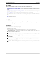
This panel shows values of individual control/data registers related to the currently selected CPU peripheral and
reflects the settings in the Bean Parameters panel.
The following two types of rows can be found in this panel:
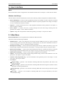
• Whole register content
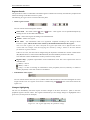
The row contains the following four columns:
Status field - This field contains
plus or
clicking the icon to show/hide individual bits.
minus - each register can be expanded/collapsed by
Name - name of the register according to the CPU datasheet.
Address - address of a register.
Init. Value - the initialization value of a register/bit computed according to the settings in Bean
Parameters panel. This is the last value written by the initialization function to the register.
Note: For some registers, the value read from the register afterwards can be different than the last
written value. For example, some interrupt flags are cleared by writing 1. Please see the CPU manual
for details on registers behavior.
If the row is active, the value can be changed using the keyboard. The field also contains a radix button
(H,D,B) that allows to switch between Hexadecimal, Decimal and Binary formats of the value.
The value that contains undefined bits is always shown in binary format.
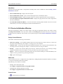
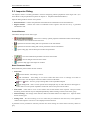
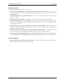
Register Map - graphical representation of the initialization value. The colors represent the state of
individual bits:
(White) = value 0
(Black) = value 1
(Gray) = bit has no meaning for initialization of the peripheral (reserved, read-only or related to
another peripheral) or the value of the bit is undefined.
• Individual bit of the register
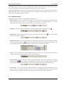
The row contains the bit value icon (0 or 1) and the name of the bit. Bits are sorted from the highest to lowest
weight. The bit rows of a register can be shown / hidden using the
register row.
/
icons in the status field of the
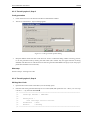
Changes Highlighting
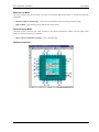
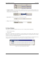
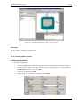
The user can immediately watch the impact of his/her changes in the Bean Parameters panel on the CPU
peripheral registers and bits values. The registers influenced by a last settings change are highlighted with a
green color (see the picture for example).
Figure 2.4 - The register affected by the parameter change
- 12 -