1
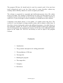
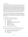
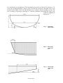
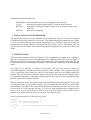
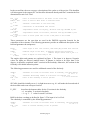
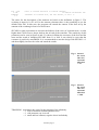
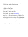
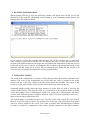
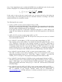
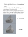
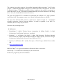
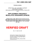
UliLines Vers. 4.4 User's Manual Copyright © 2013-2016 Ulrich Remmlinger All rights reserved latest update available at www.remmlinger.com The program UliLines 4.4 should only be used for research work. It has not been tested exhaustively and is not free from errors. It comes therefore without any warranty and no liability whatsoever can be accepted by the author. The software is protected by copyright and intellectual property laws. The author reserves all rights. The software is licensed but not sold. You may install it on your computer for your own personal use, but you may not distribute or sell the software or copies of it. If you do not agree to these conditions, you should not use the software. Compared to the initial release 3.1 the update 3.2 contains minor bug fixes. The version 4.2 was developed to design modern yachts with an almost vertical stem. It also allows a better fairing and control with additional parameters. An added feature is the hydrostatic module. In version 4.3 the Romberg method replaces the trapezoidal rule in all integrations for an improved accuracy. In 4.4 there is an additional formatoption for the output file. This file can directly be used as input to the program UliTank. Contents 1. Introduction 2. The geometric description of a sailing yacht's hull 3. The installation of UliLines 4. The input file 5. Running the program 6. The output files 7. Examples 8. References UliLines page 2 1. INTRODUCTION My work in yacht research is centered on the extended use of the computer in the design spiral. The computer is an ideal tool when it comes to multiple iteration loops as in the optimization process for the design of a sailing yacht. A detailed description of the idea can be found in [1]. A prerequisite for the automated design process is a "hands off" method for the creation of the lines plan. Based on as few input variables as possible the software should create the complete hull form in a way that the necessary parameters for the velocity prediction and stability calculation can easily be determined. It would be even more desirable, if the parameters that are used in the resistance prediction could directly be used as the input variables for the creation of the lines plan. This would enable a direct work stream in the optimization loop. The emphasis in hull creation should be put on the correct modeling of the wetted part of the hull, not on good aesthetic looks. UliLines is such a program for the parametric hull form generation of sailing yachts. It can be regarded as the automated process of the work that is normally performed by the CAD-designer in many iteration loops. The industry standard for the resistance prediction of a sailing yacht in the preliminary design phase is the formula based on a regression analysis of the Delft Systematic Yacht Hull Series. The experiments started in 1973 and the latest version of the regression coefficients was published in 2008, see [2]. The program UliLines uses the parameters of the 2008 DSYHS formula as input parameters for the creation of a lines plan. The hull form is limited to round bilge sailing yachts. 2. THE GEOMETRIC DESCRIPTION OF THE HULL The following parameters are used in the 2008 DSYHS formula. Lwl Bwl Tcb LCB LCF fpp Cp Aw Cm c Length of waterline Beam of waterline Draft of canoe body Longitudinal position of the center of buoyancy from fpp Longitudinal position of the center of flotation from fpp forward end of design waterline prismatic coefficient Waterplane area at zero speed Maximum area section coefficient Volume of displacement of canoe body A detailed definition for all these parameters is e.g. given in [3]. Based on these parameters one could create many different hull forms, the input database does not define a unique hull. Therefore, the following additional parameters are used: Alpha Gamma D BOH TOH TCL Flare angle of the maximum area section at the level of the DWL Deadrise angle of the maximum area section at the keel Depth of canoe body from keelpoint to decklevel Bow overhang Transom overhang Transom clearance UliLines page 3 For clarification, the parameters of the maximum area section are depicted in drawing 1. To avoid any misunderstanding I want to point out that the section of maximum area is not located in the middle of the Lwl and should not be confused with the midship section. The bow overhang is depicted in drawing no. 2 and the parameters describing the stern of the vessel are explained in drawing no. 3. Fig. 1. Maximum area section Fig. 2. Bow of the vessel, side view Fig. 3. Stern of the vessel, side view UliLines page 4 Additional control parameters are: TRANSOM U_SEC SECAR1 SECAR2 determines the center for the mapping of the afterbody. describes the bottom radius for the U-sections in the forebody parameter to change the fullness of the curve of sectional areas in the forebody ditto for the afterbody 3. INSTALLATION OF THE PROGRAM The zipped file that you received contains the executable file UliLines_4.4.exe, this manual ULman.pdf and several input files UL##in.txt. You should unpack the zipped file into a folder of your own choice that you have named appropriately (e.g. UliLines). You can execute the program directly in this folder by clicking on the file UliLines_4.4.exe. The output files will also be stored in this folder. If you want to uninstall the program, you just need to delete this folder. 4. THE INPUT FILE The name of the input file must be UL##in.txt. The ## stands for two digits or two characters that can be chosen by the user to distinguish between different input files. The two digits or characters will also be used in the names of the output files. The structure of the input file can best be understood by examining the example UL25in.txt that is contained in the downloaded folder. The input file is built by a sequence of line-pairs. The first line always contains an explanation and the second line the numerical value of the parameter. The program reeds only every second line and in that line only the first number until the first blank behind this number. The rest of the line is ignored. This is convenient if one wants to test different values for a parameter and wants to memorize what has been tested: just move it to the right and type the new value in the left-most position. With the exception of the Lwl, the program reeds only dimensionless parameters. If you want to change the scale of your model, you only need to change the Lwl and the rest will follow automatically. The units in the output files depend on the units that you have chosen for Lwl. If your yacht is 33 feet long and you type 33. in Line 4, then all dimensions on output will be in feet, areas in sq.ft. and volumes in cu.ft. If you type for the same yacht 10.058 in line 4, then all your results will be in meters, areas in m2 and volumes in m3. Now let's inspect the file UL25in.txt line by line Headline * Delft Series parent model Sysser 25 * Lwl Length of waterline 10.0 Lwl / Bwl Ratio of waterline length to waterline beam 4.0 UliLines page 5 In the second line, the user can type a description of the yacht or of the project. This headline will also appear in the output file. Lwl has been discussed already and line 6 contains the first dimensionless ratio Lwl / Bwl. Bwl / Tcb 5.388 Bdeck / Bwl 1.12 Cp 0.5483 Cm 0.727 LCB/Lwl 0.5199 LCF/Lwl 0.5554 Awl / Vol^2/3 6.048 Ratio of waterline beam to the draft of the canoe body Alpha 32.5 Gamma 0.0 D / Lwl 0.13463 Flare angle at max. area section, DWL-level,deg.outwrd from vertical Ratio of beam at deck level to waterline beam Prismatic coefficient of the canoe body Coefficient of the maximum area section Longitudinal center of buoyancy, distance from fpp divided by Lwl Longitudinal center of flotation, distance from fpp divided by Lwl Ratio of water plane area to the 2/3rd power of the volume These parameters are the ones that are used in the DSYHS regression formula for the estimation of the resistance. The following parameters provide an additional description of the hull and guarantee the uniqueness: Deadrise angle at the keel, in degrees upward from horizontal combine larger values with U_SEC = 0. Ratio of depth of canoe body to Lwl The angles alpha and gamma are explained in figure 1. The input is in degrees. Negative values for alpha are allowed (tumble home). If gamma is chosen to be lager than a few degrees, it should be combined with V-sections in the forebody. Otherwise, the sections in the forebody will exhibit inflection points. The following parameters are used for additional control of the forebody SECAR1 0. U_SEC 1.1 BOH / Lwl 5.8 Parameter for curve of sectional areas in forebody, see user manual or use = 0. Parameter describing radius of U-sections in forebody >1.0 = 0. for V-sections Ratio of Bow overhang to Lwl in percent SECAR1 should be initially set to 0. A slight increase to e.g. 0.1 will make the forward end of the boat fuller and create a deeper forefoot. U_SEC describes the bottom radius for the U-sections in the forebody = 0. no radius, V-section in forebody > 1. e.g. 2. – 3. value for usual U-sections BOH is the bow overhang as defined in figure 2. The input is in % of Lwl. The afterbody is controlled by the following parameters: SECAR2 0.08 TOH / Lwl 20.0 Parameter for curve of sectional areas in afterbody, see user manual or use = 0. Ratio of transom overhang to Lwl in percent UliLines page 6 TCL / TOH 0.141 TRANSOM 1.4 Ratio of transom clearance to transom overhang if unknown use default 999 Parameter for transom size, see user manual, or use = 1. The ratios for the description of the transom are based on the definition in figure 3. The overhang is input in % of Lwl. For the transom clearance there is the possibility to use the default value 999. In this case, the program will extend the contour of the keel aft by the amount of the overhang in form of a faired curve. SECAR2 is again a parameter to increase the fullness of the curve of sectional areas. A value higher than 0 will create a deeper draft at the aft end of the waterline. The sensitivity of this parameter can be seen in figures 4 and 5. It shows in Rhino the curvature of the keel and the stern and the result of changing SECAR2 from 0.1 to 0.08. It can clearly be seen, that the curvature is positively smoothened. It is recommended to start the design with SECAR2 = 0. and then slightly increase the value and watch the results. Fig. 4. Stern of the vessel, side view, curvature SECAR 2 = 0.1 Fig. 5. Stern of the vessel, side view, curvature SECAR 2 = 0.08 TRANSOM determines the center for the mapping of the afterbody. = 1. form of transom resembles main section > 1. wide transom, top is cut off < 1. small and low transom, negative shear in afterbody UliLines page 7 Finally, the CAD-program can be specified that is used to process the offset tables that are computed by UliLines. Four formats are available at the moment. CADOUT 1 specifies the output file. 1=Rhino, 2=DelftShip, 3=ProSurf, 4=UliTank The input needs to be in the integer-format 1 = file format for the Rhinoceros program 2 = file format for the Delftship program 3 = file format for the ProSurf program 4 = file format for the program UliTank Since the input file for the CAD-program FreeShip is asking for the identical format as Delftship, CADOUT = 2 can also be used for FreeShip. UliTank is not a CAD-program, but a program for the prediction of the bare hull resistance, based on tank test data. It can be downloaded at www.remmlinger.com. If the program successfully created a hull, there is the additional possibility to calculate all relevant parameters not only for the design water line, but also for different drafts. You can specify a value for the sinkage, the dimension is the same as used for the input of Lwl. The integer number in the first line tells the program how many different drafts you want to calculate. The input value for the sinkage is positive, when draft and displacement increase and it is negative, when they decrease. If the sinkage has a value of 0., the calculated distances might differ slightly from those at the design water line, because in the hydrostatic calculation Lwl is not given upfront, but found by extrapolation of the curve of immersed sectional areas. The following lines specify the immersion for hydrostatic calcul. at differ. drafts 3 no. of diff. drafts to be calculated (integer number), one line per draft -0.1 first value of sinkage relative to DWL, positive when draft increases 0.0 second value of sinkage relative to DWL, positive when draft increases 0.1 last value of sinkage relative to DWL, positive when draft increases It is advisable to save one of the downloaded input files without altering it. It can be used as a template for further input files in the future. UliLines page 8 5. RUNNING THE PROGRAM When opening UliLines_4.4.exe the following window will appear and will ask you for the identifiers of the input file (depending on the setting of your command prompt options, the background color might be black): If you want to execute the program with the input file UL25in.txt then type 25 and press enter. Instead, if you want to use the file ULCAin.txt, then type ca (not case sensitive). The program will display diagnostic messages and will indicate the termination. If the run was not successful and an error occurred, you might be able to adjust your parameters based on the indicated task that could not be solved. After termination press Enter and the window will close and you can inspect the output files in your program folder. 6. THE OUTPUT FILES The result of the computations is a table of offsets that describes the sections of the hull at 42 stations. The x-axis is the longitudinal axis of the hull, the y-axis is parallel to the water surface and the z-axis runs vertical from the water surface downwards. The origin of the system is on the water surface at the forward end of the design water line at rest. Somebody might wonder about the large number of points that are used to describe the outline of the sections. This was the result of a comparison of the intended outline with the result after lofting in the CAD-program. With fever points the CAD-programs "invented" sections with inflection points or negative deadrise angles. This was especially severe for Ushape sections with a radius at the keel. The wetted surface is calculated in two ways. The first value in the output file is the sum of the true area of the surface panels. The second value is the sum of the projection of the panel area to a surface parallel to the x-axis. This value is needed when calculating the frictional resistance, as only the x-component of the surface friction contributes to the total resistance UliLines page 9 force. If the length/beam ratio is within the DSYHS, then an additional value for the wetted surface is displayed. It is calculated using the Delft-regression formula: Awet B 1.97 0.171 wl Tcb 0.65 3 C Lwl Cm 1 If this value is close to the true wetted surface one can expect the hull to fall within the covered range of the Delft-regression and the calculated resistance according to the Delftmethod should also be reasonably accurate. The following files are created: 1. ULOut_25.TXT or in the second example ULOut_ca.TXT This text file contains the dimensions of the created hull. The appropriate units depend on the unit of Lwl, as described in chapter 4. Metacentric height, wetted surface, water plane area and volume of displacement are also displayed. If the input file asked for a hydrostatic calculation, then there is a table added to the output file that displays the parameters needed for the Delft-regression at the different drafts. 2. ASEC_25.CSV or in the second example ASEC_ca.CSV Many Excel-programs can read this file and you can create your own curve of sectional areas with the data in this file. 3. For CADOUT=1 the file Rhino_25.TXT or in the second example Rhino_ca.TXT This scripting can be read by Rhino. You should first adjust the global tolerance. Go to >File >Properties >Units and set the absolute tolerance to 1e-6 (for a model that is measured in meters). After that, you can read the curves. From Menu in Rhino use >Tools >Commands >Read from file > go to the file "Rhino_25.TXT" and open it. It can take minutes until all curves are read and the surface is computed. I recommend switching the isocurves off. This improves the visibility of the colors when doing a curvature analysis. 4. For CADOUT=2 the file DelftS_25.TXT or in the second example DelftS _ca.TXT This table of offsets can be read by Delftship. If the Lwl is measured in feet, please change the first number from 0 to 1. Select File > Import > Surface > go to the file "DelftS_25.TXT" and open it. The program will display the hull within seconds. 5. For CADOUT=3 the file ProSurf_25.NWS or in the second example ProSurf_ca.NWS This table of offsets can be read by ProSurf. From Menu in ProSurf go to File > Data File Input > NWS Input > go to the file ProSurf_25.NWS and open it. The program will display immediately all sections. Then you go > Create 3D > Sin/Loft Surf (as described in ProSurf-Help) 6. For CADOUT=4 the file OFFS_025.TXT or in the second example OFFS_0ca.TXT This table of offsets can be read by UliTank. Just move the file into the folder OFFSETS that is contained in the Zip-file UliTank, which can be downloaded at www.remmlinger.com. UliTank performs a resistance prediction based on a regression analysis of tank test data. UliLines page 10 7. If Lwl/Bwl is > 7 the file ca_sploff1.csv This is an input file for Michlet, see [4]. It contains the hull offsets in the spline format. If you change the name to sploff1.csv, you can copy this file directly into the Michlet-folder and, after modifying the in.mlt file, run Michlet. 7. Examples There are five different input files in the zipped folder that demonstrate some of the capabilities of the program. The files UL01in.TXT and UL25in.TXT try to match the lines plans of two models of the DSYHS as closely as possible. "01" uses the parameters of the parent model Sysser 1 and "25" those of the parent model Sysser 25. Sysser 1 is designed with V-sections in the forebody, whereas Sysser 25 has U-sections. The input file UL40in.TXT demonstrates the added capabilities of the revision UliLines_4.3. It tries to simulate the hull of a Class 40 yacht with a vertical stem and a wide and flat afterbody. The hullform is very demanding on the CAD-system because there are sudden changes from almost flat surfaces to ones with very high curvatures. CAD-systems like Unigraphics or Solidworks have no problem with the lofting of such sections, but less sophisticated systems as Rhino create wrinkles at the bilge in the forebody, see figure 6. Fig. 6. Lofted sections in Rhino Fig. 7. Surface from curve network in Rhino UliLines page 11 The problem is solved by using the _NetworkSrf command in Rhino instead of _Loft. For this purpose, 3 additional longitudinal "stringers" are added to the end of the input file. The result is depicted in figure 7. Should there still be folds or wrinkles in the surface I recommend to delete the surface, use the _NetworkSrf command manually and set the tolerance in the dialog box to 1e-6 (for a model that is measured in meters). The input file UL85in.TXT is included to demonstrate the influence of a large prismatic coefficient (0.85). The program creates a very "boxy" hull, but the lines are still fair. The input file ULCAin.TXT produces a hull that is slender enough for a meaningful resistance prediction with the program Michlet. It could be regarded as one hull of a catamaran, but it is really only a test case. Good luck for your design work! 8. References 1. Remmlinger U. (2006), "Design Process Automation for Sailing Yachts", 2nd High Performance Yacht Design Conference, Auckland 2. Keuning, J. A. & Katgert, M. (2008), "A Bare Hull Resistance Prediction Method Derived from the Results of the DSYHS Extended to Higher Speeds", Innovation in High Performance Sailing Yachts, Lorient, France, RINA, pp 13-21. 3. Larsson, L. & Eliasson, R. E. (1994), Principles of Yacht Design, Adlard Coles, London GB 4. www.cyberiad.net/leo.htm RHINOCEROS® is a registered trademark of Robert McNeel & Associates DELFTshipTM is a trademark of Delftship BV, the Netherlands ProSurf is a program by Steven M. Hollister UliLines page 12