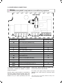
1
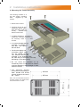
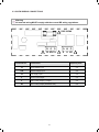
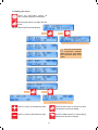
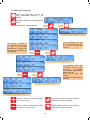
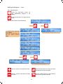
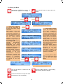
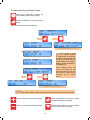
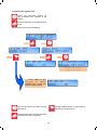
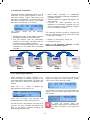
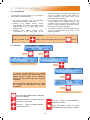
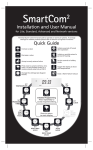
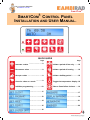
Visit our Support Database
at www.s-i-d.co.uk
SmartCom 3
SMARTCOM 3 CONTROL PANEL
INSTALLATION AND USER MANUAL.
QUICK QUIDE
Page
Page
Increase a value ...…….……………9
Initiate a period of fan only ....…18
Decrease a value ...……..….………9
Initiate a period of heating ….…18
Accept a value ..…………....………9
Initiate a holiday period ...……...18
Cancel a value or a mode ..…….…9
Toggle the temperature display 18
Initialise programming ...…......…10
Clear a flame failure lockout .….19
…....……………11
..………………17
...….……………12
..………………19
...….……………14
.....….…………21
…....……………15
..………………22
…....……………16
INDEX
Section
Technical Specifications
1.1 Operating Environment ------------------------------------------------------------------------------------- 3
1.2 Performance Specifications -------------------------------------------------------------------------------- 3
1.3 SC3FM Facia Mount Electrical Specifications --------------------------------------------------------- 3
1.4 SC3SZ Single Zone Electrical Specifications --------------------------------------------------------- 3
1.5 SC3MZ Multi Zone Electrical Specifications ----------------------------------------------------------- 3
Installation Instructions
2.1 Mounting the Control Assembly --------------------------------------------------------------------------- 4
2.2 General Wiring Specifications ----------------------------------------------------------------------------- 5
2.3 SC3FM Version Wiring Connections -------------------------------------------------------------------- 6
2.4 SC3SZ Version Wiring Connections --------------------------------------------------------------------- 7
2.5 SC3MZ Version Wiring Connections -------------------------------------------------------------------- 8
Operating Instructions
3.1 Factory default settings ------------------------------------------------------------------------------------- 9
3.2 The Buttons ---------------------------------------------------------------------------------------------------- 9
3.3 The Settings button -----------------------------------------------------------------------------------------10
3.4 Setting the clock ---------------------------------------------------------------------------------------------11
3.5 Setting the Program (on/off times) ----------------------------------------------------------------------12
3.5.1 Copying the Programs -----------------------------------------------------------------------------------13
3.6 Setting the Modes--------------------------------------------------------------------------------------------14
3.7 Setting day and night temperatures ---------------------------------------------------------------------15
3.8 Setting the system OFF ------------------------------------------------------------------------------------16
3.9 Optional Passwords ----------------------------------------------------------------------------------------17
3.10 Checking the temperature -------------------------------------------------------------------------------18
3.11 Setting a temporary Holiday period -------------------------------------------------------------------18
3.12 Setting a temporary Overtime extension period ----------------------------------------------------18
3.13 Setting a temporary Vent period -----------------------------------------------------------------------18
3.14 Display messages -----------------------------------------------------------------------------------------19
3.14.1 Error message:- Lockout ------------------------------------------------------------------------------19
3.14.2 Exam period ----------------------------------------------------------------------------------------------19
3.14.3 Optimum Start and Optimum Stop ------------------------------------------------------------------19
3.14.4 Service hours ---------------------------------------------------------------------------------------------19
3.14.5 External Sensor fault indication ----------------------------------------------------------------------19
3.14.6 External Inputs -------------------------------------------------------------------------------------------20
3.14.6.1 External Input priority --------------------------------------------------------------------------------20
3.15 Network Controllers ---------------------------------------------------------------------------------------21
3.15.1 Operating the Master -----------------------------------------------------------------------------------21
Engineer Functions
4.1 Introduction ---------------------------------------------------------------------------------------------------22
4.2 Settings --------------------------------------------------------------------------------------------------------22
4.3 The Engineer Variables ------------------------------------------------------------------------------------23
Battery Cell information
5.1 Battery replacement ----------------------------------------------------------------------------------------26
5.2 Battery specification ----------------------------------------------------------------------------------------26
2
Introduction
In order to satisfy the increasing need for
higher efficiencies and to complement the
development of efficient heating systems
Ambi-Rad has upgraded their ‘SmartCom’
range of controllers.
multi-zone applications requiring centralised
control. This operating manual gives simple
step by step instructions for both the end user
and commissioning engineer alike.
This control must be installed according to
the current IEE Wiring Regulations and
should include full disconnection means and
fusing appropriate to the connected loads.
With a new larger, back lit screen and simpler
to operate with intuitive programming,
SmartCom³ provides cost effective energy for
small single heater installations through to large
1
Technical Specifications.
Remote duct temperature sensor.
1.1 Operating Environment
•
•
•
•
•
•
•
•
Measuring range:
Resolution:
Accuracy over range:
Operating temperature range: 0º C to 40º C
Operating humidity range: 0 to 90% RH.
Control IP rating: IP30
Pollution degree: II environment
Control safety construction: class II
Mains supply: 230Vac nominal, 200Vac to
253Vac actual, 50Hz.
On board supply fuse: 1AT
Rated impulse voltage: 2500V
1.3 SC3 FM Electrical Specifications.
Burner reset, Heat and
Vent 1 relay rating:
Power consumption:
1.2 Performance Specifications
•
•
•
•
•
•
•
7A/240Vac resistive
2A/240Vac inductive
2.5W
1.4 SC3 SZ Electrical Specifications
Burner reset, Heat and
Time relay rating:
Operation is by Class A software and Type
1A action. Version 1a
The mains supply to the electronic circuit is
protected by a time delay fuse.
Flame failure input: 230Vac nominal,
200Vac to 253Vac actual, 50Hz. Presence
of voltage indicates flame failure.
The burner reset relay output is either Live
or Neutral which is selected by a plug-in
jumper (Live only - SC3 FM version).
Remote volt-free switch outputs will be
24Vdc/5mA
The built-in room temperature sensor has a
measuring range of 0º C to 30º C with a
resolution of 0.2º C.
Temperature sensor readings can be offset
to allow for errors due to sensor tolerances
and location. NB Frost protection readings
are also affected by offsets.
550W Vent 1 relay
rating:
Power consumption:
7A/240Vac resistive
2A/240Vac inductive
10A/240Vac resistive
3A/240Vac inductive,
(550W single phase
motor, max)
2.5W
1.5 SC3 MZ Electrical Specifications
All relays except Vent
1 rating:
Vent 1 relay rating
Power consumption:
Built-in and remote room temperature sensor.
Measuring range:
Resolution:
Untrimmed accuracy over
range:
Accuracy over range with
offset:
10 – 60º C.
0.2º C.
+/- 3.0º C.
Communications
wiring:
0 – 30º C.
0.2º C.
+/- 1.4º C.
0 – 10V signals
+/- 0.6º C.
10A/240Vac resistive
2A/240Vac inductive
10A/240Vac resistive
3A/240Vac inductive,
(550W single phase
motor, max)
5W
5W Screened twisted
pair Daisy-chain
configuration.
Belden 9841 (or
equiv) recommended.
Max length = 500m
Output impedance =
500 Ohm.
Max current drive
capacity = 5mA
The power supply is SELV isolated, therefore
low voltage wiring to the control does not need
to be mains level rated.
Unless well ventilated, heat generated in the
controller may cause the built-in sensor to
over-read temperatures.
3
2
Installation instructions.
2.1 Mounting the Control Assembly
The housing consists of a
two part plastic moulding
held
together by four
screws.
• Remove the screws.
• Carefully lift the lid and
unplug the ribbon cable
from the power PCB assembly
situated in the
bottom of the case.
• A drilling template is provided to
enable the controller assembly to
be securely fixed to a solid
surface.
• It is recommended that the
controller is installed no
less than 1.5m above
the floor level.
• The lid with display and
connecting ribbon cable
can be rotated through
180° therefore allowing the
controller to be positioned with
the cable entry to the bottom or the top
depending on the cable routing.
• Do not mount the controller on an
excessively warm or cold surface or where it
could be affected by direct sunlight or other
heat/cool sources.
• The mounting surface
should be non-conducting or
earth bonded and should
prevent access to the rear of
the control.
224 mm
200 mm
4
128 mm
80 mm
Note: The recommended minimum
mounting height only applies when
the internal sensor is used.
Note: when used in dusty/contaminated
environments it may be necessary to locate
the SmartCom panel within an enclosure (or
locate panel remotely) and use an external
temperature sensor.
Please refer to the following wiring connection
drawings and observe the note at the bottom of
each page referring to cable type and length.
Complete installation wiring instruction booklets
are supplied to suit individual heating
applications which can also be downloaded
from our support database by going to
www.s-i-d.co.uk
2.2 General Wiring Specifications
All wiring connections must be made by a
suitably qualified person.
It is important to read both the product
instructions and these control instructions to
ensure satisfactory operation.
When making connections to screw terminals
please ensure that no more than 6mm of
insulation is stripped back and that no stray wire
strands escape.
Failure to follow these guidelines may result in
electrical interference or unsatisfactory
operation.
5
2.3 SC3FM WIRING CONNECTIONS
Warning
All external wiring MUST comply with the current IEE wiring regulations.
! FUSE RATING
!
Terminal No.
10 2/N 1/L
Connection
!
9 6 40
!
Capacity mm²
10
Flame failure input
2.5
2/N
Neutral supply input
2.5
1/L
Live supply input
2.5
9
Burner reset output
2.5
6
Heat 1 relay output (1 stage)
2.5
Vent 1 relay output (550W/low fan)
2.5
40
6
2.4 SC3SZ WIRING CONNECTIONS
Warning
All external wiring MUST comply with the current IEE wiring regulations.
FUSE RATING
!
NEUT
LIVE
!
!
!
41 40 9 5 6
Terminal No.
1/L 2/N 10
Connection
B1 B0 B2 S/R0S/R1
Capacity mm²
41
Vent 1 relay input (550W/low fan)
2.5
40
Vent 1 relay output (550W/low fan)
2.5
9
Burner reset output
2.5
5
Time relay output
2.5
6
Heat 1 relay output (1 stage)
2.5
1/L
Live supply input
2.5
2/N
Neutral supply input
2.5
10
Flame failure input
2.5
B1
Remote on input (BMS ON input)
1.5
B0
Remote common (output to BMS)
1.5
B2
Remote frost input (door interlock)
1.5
S/R0
Remote room temperature sensor ‘A’
1.5
S/R1
Remote room temperature sensor ‘B’
1.5
control unit, using screened 6A mains* cable.
Connect the screen to terminal B0.
A terminal block is supplied to enable multiple
connections to B0/B2 as detailed in product
wiring connections.
All sensor and signal wiring should be kept
separate from mains wiring to minimise noise
pick-up.
Remote switch inputs should be connected by
6A mains* cable of maximum length 100m. The
remote temperature sensor may be placed at a
distance of up to 100m (maximum) from the
*The power supply is non-isolated, therefore all wiring to the
control must be mains rated.
7
2.5 SC3MZ WIRING CONNECTIONS
Warning
All external wiring MUST comply with the current IEE wiring regulations.
! FUSE RATING
LIVE
41 40 7 8
Terminal No.
41
40
7
8
9
25
14
5
6
1/L
2/N
10
S/R0
S/R1
D0
D1
O0
O1
B1
B0
B2
C2
C0
C1
66
64
20
9 25
14 5 6
NEUT
T
!
1/L 2/N 10
S/R0S/R1 D0 D1 O0 O1 B1 B0 B2 C2 C0 C1 66 64 20
Connection
Capacity mm²
Vent 1 relay input (550W/low fan)
Vent 1 relay output (550W/low fan)
Heat 2 relay input (2 stage)
Heat 2 relay output (2 stage)
Burner reset output
Vent 3 relay output (damper)
Vent 2 relay output (high fan)
Time relay output
Heat 1 relay output (1 stage)
Live supply input
Neutral supply input
Flame failure input
Remote room temperature sensor ‘A’
Remote room temperature sensor ‘B’
Remote duct temperature sensor ‘A’
Remote duct temperature sensor ‘B’
Outside air temperature sensor ‘A’
Outside air temperature sensor ‘B’
Remote on input (BMS ON input)
Remote common (output to BMS)
Remote frost input (door interlock)
Comms connection ‘A’ input/output (Networking)
Comms connection ‘GND’ output (Networking)
Comms connection ‘B’ input/output (Networking)
Channel 1, 0~10V output (GM44)
Channel 1 and 2 common output
Channel 2, 0~10V output (damper
A terminal block is supplied to enable multiple
connections to B0/B2 as detailed in product
wiring connections. 0-10V outputs and remote
switch inputs should be connected by 0.75mm2
cable of maximum length 100m. The remote
temperature sensor may be placed at a
distance of up to 100m (maximum) from the
control unit, using screened 0.75mm2 cable to
88
2.5
2.5
2.5
2.5
2.5
2.5
2.5
2.5
2.5
2.5
2.5
2.5
1.5
1.5
1.5
1.5
1.5
1.5
1.5
1.5
1.5
1.5
1.5
1.5
1.5
1.5
1.5
improve noise rejection. Connect the screen to
terminal B0. Master-slave communication is by
screened twisted pair cable, RS 485 compatible,
such as Belden 9841 (or Equiv). Maximum
overall system length is 500m. Connect screens
to B0 and C0. All sensor and signal wiring should
be kept separate from mains wiring to minimise
noise pick-up.
3
Operating instructions.
3.1 Factory default settings
OFF time
16:30 Mon thro Fri
(no further ON/OFF times set or weekends)
Program mode
Auto
Control type
Warm Air*
Sensor type
Internal*
Night setback
On*
Frost protection
On*
Networking
Off*
Pin protection
Off*
For speedy installation and ease of first
operation, the SmartCom³ is supplied from the
factory with pre-programmed default settings.
These are:
On / Day temperature
18°C
Off / Night temperature 5°C
ON time
08:00 Mon thru Fri
* can be altered within Engineers settings if required.
3.2 The Buttons
The ten buttons have the following functions:
Pressing the UNDO button, at any time will
cancel this operation.
Press the + button to increase a value.
The controller can operate in holiday
mode, with frost protection for a number
of days. When the holiday period
expires the controller returns to normal
operation. Pressing the UNDO button, at any
time will cancel this operation.
Press the - button to decrease a value.
Press the OK button to accept the value
and advance to the next display.
Pressing the CHECK TEMP button will
display the sensor (room) temperature
on the first press and the set (program)
temperature on the second press. The third
press will return the display to normal.
Press to cancel overtime, vent, exam*,
OFF and holiday modes or to cancel a
setting but save any previous changes.
Pressing the LOCKOUT button will clear
a flame failure lockout. In order to reset
the lockout, press and release the
LOCKOUT button. After 10 seconds the
controller will return to normal operation. The
lockout warning and LED will continue to display
if the flame failure signal is cleared at source.
Initialise and step through programming
modes.
Pressing the FAN ONLY button will
force the controller to operate Vent 1
r e l a y r eg ar d l ess o f th e ro om
temperature while Heat relays are disabled.
Pressing the UNDO button, at any time will
cancel this operation.
Note:
If no keypad action takes place for 60
seconds, the current selection is cancelled
and the display returns to day and time and
previously set operating mode.
Pressing the OVERTIME button in an
OFF period will initiate or extend the
day-time operation of the controller.
* Exam Heating mode (EH) will appear only if
selected in the engineer functions.
9
3.3 The SETTINGS button
Pressing the SETTING button will scroll
through the user options in the following
sequence. Repeated pressing of this
button will loop these options round to the start.
Th 09 : 30
AUTO
ON
press
Allows the user to set
the hour, minute, day,
month and year.
SET CLOCK?
OK =yes SET =next
press
Allows the user to set
up to 3 time period per
day. Auto matic copy
function available.
SET PROGRAM?
OK =yes SET =next
press
Allows the user to set
the operating relevant
mode to the application.
SET MODE?
OK =yes SET =next
press
Allows the user to set
day
and
night
temperatures.
SET TEMPS?
OK =yes SET =next
press
Allows the user to
switch all functions to
an OFF status.
SET SYSTEM OFF?
OK =yes SET =next
press
Menu End
OK =yes SET =redo
press
Th 09 : 30
AUTO
ON
10
or
3.4 Setting the Clock
Press the SETTING button till
SET CLOCK? appears in the display.
Press the OK button to change this user
mode.
SET CLOCK?
OK =yes SET =next
Value to alter/confirm will start flashing.
press
or
SET Day Mo 09 : 29
+ or - then OK
SET PROGRAM?
OK =yes SET =next
follow ‘Setting the PROGRAM’ menu
SET Hrs Mo 09 : 29
+ or - then OK
SET Mns Mo 09 : 29
+ or - then OK
Clock will automatically
compensate between
British Summer Time (BST)
and Greenwich Mean Time
(GMT)
SET Dat 18 - 06 - 09
+ or - then OK
SET Mon 18 - 06 - 09
+ or - then OK
SET Yr
18 - 06 - 09
+ or - then OK
Menu End
OK =yes SET =redo
press
Th 09 : 29
AUTO
ON
or
SET Day Mo 09 : 29
+ or - then OK
repeat above procedure
Use the + button to increase the value.
Press the OK button to accept the value
and advance to the next display.
Use the - button to decrease the value.
Press the UNDO button to cancel setting
but save any previous changes.
11
3.5 Setting the Programs
Press the SETTING button till
SET PROGRAM? appears in the
display.
SET PROGRAM?
OK =yes SET =next
Press the OK button to change this user
mode.
press
Value to alter/confirm will start flashing.
If the - button is
pressed at an unused
time slot “--:--”, the screen
advances to a further ON
time. The new ON time will
start flashing.
SET Day Mo
+ or - then OK
Mo ON
1 08 : 00
+ or - then OK
Mo OFF 1 16 : 30
+ or - then OK
Mo ON
2 --: -+ or - then OK
press
Mo ON
2
+ or - then
Mo OFF 2
+ or - then
Mo ON
3
+ or - then
press
Mo ON
3 20 : 30
+ or - then OK
Mo OFF 3 22 : 00
+ or - then OK
Copy to Tu
OK =yes SET =next
or
SET MODE?
OK =yes SET =next
follow ‘Setting the MODE’ menu
3 timeslots per day
(each timeslot includes
an on and off time) are
allowed.
or
Copy to Tu
OK =yes SET =next
17 : 30
OK
20 : 00
OK
--: -OK
follow copy function menu
or
Copy to Tu
OK =yes SET =next
Pressing
the
OK
button at an unused
time slot “--:--”, will display
the automatic copy function.
(see next page).
Press OK to copy day
settings.
Press SET to alter times for
that day.
follow copy function menu
follow copy function menu
Use the + button to increase the value
in 10 minute steps.
Press the OK button to accept the value
and advance to the next display.
Use the - button to decrease the value.
the value in 10 minute steps.
Press the UNDO button to cancel setting
but save any previous changes.
12
Setting the Program …...cont.
3.5.1 Copy Function
Press the SETTING button till
SET PROGRAM? appears in the
display.
Press the OK button to change this user
mode.
Copy to Tu
OK =yes SET =next
Value to alter/confirm will start flashing.
press
Press OK to copy day
settings.
Press SET to alter times for
that day. (follow previous
page)
or
Copy to We
OK =yes SET =next
Copy to Th
OK =yes SET =next
SET Day Tu
+ or - then OK
follow ‘Setting the PROGRAM’ menu
Copy to Fr
OK =yes SET =next
Copy to Sa
OK =yes SET =next
Copy to Su
OK =yes SET =next
MENU END
OK =yes SET =redo
press
Th 09 : 40
AUTO
ON
or
SET Day Mo
+ or - then OK
follow PROGRAM menu
Use the + button to increase the value.
Press the OK button to accept the value
and advance to the next display.
Use the - button to decrease the value.
the value.
Press the UNDO button to cancel setting
but save any previous changes.
13
3.6 Setting the Mode
Press the SETTING button till
SET MODE? appears in the display.
Press the OK button to change this user
mode.
SET MODE?
OK =yes SET =next
press
or
SET AUTO MODE?
OK =yes SET =next
Press SET to advance
to the next mode to
choose. Press OK to accept
new mode.
Auto mode: Heating and
ventilation
operate
automatically depending on
the room temperature, time/
set temperature program
and the control method
selected. Ventilation is
disabled during off periods
of the time program.
Frost Only mode: Heating
operates
automatically
depending on the room
temperature and control
method selected. The set
temperature is fixed at 5°C.
Ventilation is disabled.
Fan Only mode: Ventilation
operates automatically
depending on the room
temperature,
time/set
temperature program and
the control method selected.
H e a ti n g i s
disabled.
Ventilation is disabled during
off periods of the time
program.
SET TEMPS?
OK =yes SET =next
follow ‘Setting the MODE’ menu
press
SET EXAM MODE?
OK =yes SET =next
SET FROST ONLY?
OK =yes SET =next
SET HEAT ONLY?
OK =yes SET =next
SET FAN ONLY?
OK =yes SET =next
Menu End
OK =yes SET =redo
press
Exam Heating mode:
If the control is used
on a system installed in a
sports hall, a temporary
increase in temperature can
be set to improve comfort for
people sitting in the building.
Heating will be controlled to
“temperature 2”. Exam
Heating mode can only be
set during an ON period and
will last only until the next
OFF period unless cancelled
by the UNDO button.
Heat Only mode: Heating
operates automatically
depending on the room
temperature,
time/set
temperature program and
the control method selected.
Ventilation is disabled.
Pressing SET at ‘Menu
End’ will scroll round
back to the first mode
setting.
or
SET AUTO MODE?
OK =yes SET =next
Th 09 : 30
HEAT
ON
repeat procedure above
Use the SET button to advance to the
next display.
Press the UNDO button to cancel setting
but save any previous changes.
Press the OK button to accept the value
and advance to the next display.
14
3.7 Setting the Day and Night Temps
Press the SETTING button till
SET TEMP? appears in the display.
Press the OK button to change this user
mode.
Value to alter/confirm will start flashing.
SET TEMPS?
OK =yes SET =next
press
or
DAY TEMP
16 . 0 O C
+ or - then OK
SET SYSTEM OFF?
OK =yes SET =next
follow ‘SYSTEM OFF’ menu
*
EXAM TEMP 18 . 0 O C
+ or - then OK
NITE TEMP
5 . 0 OC
+ or - then OK
Menu End
OK =yes SET =REDO
press
Th 09 : 30
AUTO
ON
or
If the control is used
on a system installed
in a sports hall, a temporary
increase in temperature can
be set to improve comfort for
people sitting in the building.
Heating will be controlled to
“temperature 2”.
Exam Heating mode can
only be set during an ON
period and will last only until
the next OFF period unless
cancelled by the UNDO
button.
DAY TEMP
18 . 0 O C
+ or - then OK
repeat above procedure
*Note: Exam heating mode will only appear if selected in the engineers functions.
Use the + button to increase the value.
Press the OK button to accept the value
and advance to the next display.
Use the - button to decrease the value.
Press the UNDO button to cancel setting
but save any previous changes.
15
3.8 Setting the System OFF
Press the SETTING button till
SET SYSTEM OFF? appears in the
display.
Press the OK button to change this user
mode.
Value to alter/confirm will start flashing.
SET SYSTEM OFF?
OK =yes SET =next
press
SYSTEM OFF
UNDO = reset
press
or
Menu End
OK =yes SET =redo
press
or
Th 09 : 32
AUTO
ON
SET CLOCK?
OK =yes SET =next
Repeats User settings.
follow CLOCK menu
Press UNDO at any
time
to
cancel
SYSTEM OFF. System will
revert to original control.
Th 09 : 32
AUTO
ON
Use the SET button to advance to the
next display.
Press the UNDO button to cancel setting
and revert to original contol.
Press the OK button to accept the value
and advance to the next display.
16
3.9 Optional Password (PIN protection)
To protect the entered settings, you can use a
password PIN code. This unique 4 digit PIN
code will be required to change the settings that
you have stored and will prevent unauthorised
amendment of the settings.
P I N ENTER
0000
+ /- /OK
Refer to the Engineers Settings of this
manual to activate this option.
Note: PIN protection is not initiated as a default
setting.
P I N ENTER
3000
+ /- /OK
Press + or - button to
set the first number
then press the OK button.
The next digit will start
flashing to be set.
Continue till last number is
entered.
The final press of the OK
button will allow settings to
be modified.
PIN 3254 shown opposite
is an example only.
P I N ENTER
3000
+ /- /OK
P I N ENTER
3200
+ /- /OK
P I N ENTER
3200
+ /- /OK
P I N ENTER
3250
+ /- /OK
P I N ENTER
3250
+ /- /OK
P I N ENTER
3254
+ /- /OK
Th 09 : 32
AUTO
ON
*If you forget the PIN code there is a Master PIN code that is factory set by the manufacturer.
This Master PIN code over-rides the unique PIN code and will enable you to change the PIN code
again. Please call the manufacturer for this Master PIN code.
Use the + button to increase the value.
Press the OK button to accept the value
and advance to the next display.
Use the - button to decrease the value.
the value.
Press the UNDO button to cancel setting
but save any previous changes.
17
The holiday period will start at midnight on the
day that it is initiated. From then on the
‘HOLIDAY’ along with the remaining number of
days will be displayed. When the holiday period
expires the controller returns to normal
operation.
Pressing the UNDO button, at any time will
cancel the holiday period.
3.10 Checking the temperature
Pressing the CHECK TEMP button will
display the sensor (room) temperature
on the first press and the set (program)
temperature on the second press. The third
press will display the *outside temperature if set
within engineer settings or return the display to
normal.
3.12 Setting an overtime extension period
NB. The display will return to normal 10
seconds after the second press if CHECK
TEMP is not again.
ROOM TEMP
16 . 6 O C
Pressing the OVERTIME button in an
OFF period will initiate or extend the
day-time operation of the controller.
Overtime is activated as follows:
SET TEMP
18 . 0 O C
Press the OVERTIME button. ‘OVERTIME’ will
be displayed and the hours and minutes digits
will flash.
* O/S TEMP
30 . 0 O C
OVERT I ME
Press the + or – buttons to increase or decrease
the required amount of time in 10 minute
increments. (Values between 0 and 60 minutes
are acceptable by default. The range can be
extended up to 10 hours in the Engineer
Functions).
Pressing the CHECK TEMP and the + button
together will display the duct temperature (if
fitted) . The display will return to normal after 10
seconds if not cancelled by UNDO.
OVERT I ME
3.11 Setting a temporary Holiday period
The controller can operate in holiday
mode, with frost protection, for a
number of days. The holiday mode is
set as follows:
OVERT I ME
0 1 : 59
UNDO = reset
0 days
+ /- /OK
Pressing the UNDO button, at any time will
cancel this operation.
Press the + or – button to increase or decrease
the number of holiday days. (Values from 00 to
31 are acceptable). Zeros ‘00’ indicates no
holiday period set.
HOL I DAY
02 : 00
+ /- /OK
Press OK to accept the setting. The display will
show the overtime minutes remaining. When the
overtime period expires the controller returns to
normal operation.
Press the HOLIDAY button. ‘HOLIDAY’ will be
displayed and the number of days will flash.
HOL I DAY
00 : 00
+ /- /OK
3.13 Setting a temporary Fan period
Pressing the FAN ONLY button will force
the controller to operate Vent 1 relay
regardless of the room temperature
while Heat 1 and Heat 2 relays are disabled and
Vent 2 and Vent 3 relays operate according to
the room temperature. The FAN ONLY period is
activated as follows:
7 days
+ /- /OK
Press the OK button to accept the holiday
setting. ‘HOLIDAY SET’ will be shown along
with the normal display until the start of the
holiday period.
Press the FAN ONLY button. ‘FAN ONLY’ will be
displayed and the hours and minutes digits will
flash.
Fr 16 : 58
HOL I DAY SET
18
FAN ONLY
00 : 00
+ /- /OK
This warning will continue to display until the
next time switch or until the undo button is
pressed.
Press the + or – buttons to increase or
decrease the required amount of time in 10
minute increments. (Values between 0 and 60
minutes are acceptable by default. The range
can be extended up to 10 hours in the
Engineer Functions).
FAN ONLY
3.14.3 Optimum Start and Optimum Stop.
This feature is factory set. If not required, refer to
the Engineer Functions. Optimum start is an
energy saving feature which turns the heating
system on at the latest possible time, whilst
ensuring that the desired temperature is
achieved at the ON time.
0 1 : 00
+ /- /OK
Press OK to accept the setting. The display will
show the overtime minutes remaining. When
the overtime period expires the controller
returns to normal operation.
When the controller is optimising, the following is
displayed. Ventilation remains disabled during
the optimum start period.
FAN ONLY
00 : 59
UNDO = reset
We 07 : 32
OPT ON
AUTO
Pressing the UNDO button, at any time will
cancel this operation.
Towards the end of a heating period the
controller may turn off the heating early.
The optimum stop period is calculated and
relates to the speed of response of the building.
The optimum stop period is a factor of the
optimum start historical information and will be
limited to the maximum time period set in the
engineer functions. The controller will only allow
the temperature to fall by up to 2°C below the set
point during this period. Ventilation is disabled
during the optimum stop period.
3.14 Display Messages.
3.14.1 Lockout Error
When the controller detects a flame failure
signal, the screen will show a LOCKOUT
display and the red LED will illuminate.
M
ARN I NG !
LOCKOUT
When the controller is optimising, the following is
displayed.
The lockout warning and LED will
continue to display if the flame failure
signal is cleared at source.
We 16 : 26
AUTO
OPT OFF
In order to reset the lockout, press and release
the LOCKOUT button. After 10 seconds the
controller will return to normal operation.
3.14.4 Service Hours
The controller has a programmed burner hour
limit. This is default at 1200 hours but can be
adjusted within the Engineers codes.
NB. The lockout will not be displayed for the
first 45 seconds after initial burner start. Fan
and heating outputs will continue to function
normally despite the lockout condition.
Once the heater has reached this set limit, the
screen will show A SERVICE HOURS display to
register that a service is due.
3.14.2 Exam period
Th 09 : 32
SERV I CE HOURS
If the control is used on a system installed in a
sports hall, a temporary
increase in
temperature can be set to improve comfort for
people sitting in the building. The screen will
show an EXAM MODE display.
3.14.5 External sensor fault indication
Th 09 : 32
EXAM MODE
If an external sensor is used/set within Engineers
settings but the sensor is open circuit, the display
19
M
will the following error:
ARN I NG !
LOCKOUT
A I RFLO
M
ROOM TEMP -5 . 0 C
O
NB. The controller will ignore the input for the
first 30 seconds.
3.14.6 External Inputs
As a multipurpose alarm the control will display
“REMOTE OFF - CHECK” and the heating
operation will be suspended until the fault is
corrected.
There are two external inputs for direct control
of the operating mode of the system.
M
ARN I NG !
REMOTE OFF - CHECK
The ON input forces the controller to operate in
the on mode for as long as the input is active
(switch closed). This could be used for an
override on switch or for BMS control.
NB. The controller will ignore the input for the
first 30 seconds
Note: If the controller is to be used in a BMS
system then all of the ON times should be set
as unused, then the controller will by default
control at off/night temperature. The BMS
system can then activate on/day or frost
temperature control using the external inputs.
Further in a multi-zone system air flow failure on
a slave will be displayed on the Master as a
lockout with the zone number and lockout reset
can be achieved either locally on the affected
slave or centrally using the Master controller.
EXTERNAL / BMS
AUTO
As a multipurpose alarm the input will be
effective at all times, whereas in air flow failure
and blocked filter modes the controller will ignore
the input until 30s from the start of either the heat
or time relays as set under the engineers menu.
The FROST input forces the controller to
operate in the frost mode for as long as the
input is active (switch closed). This could be
used as a holiday switch or an off switch or as a
door interlock to turn the heating off when a
door is open or for BMS control.
In a multi-zone system the external inputs to the
Master controller will be applied to all zones
automatically, however individual zones can be
set to ignore the FROST signal from the Master
under the engineers menu. The external inputs
to a slave controller will apply to that zone only.
EXTERNAL / DOOR
FROST ONLY
3.14.6.1
items.
In addition the remote Frost input can be
assigned under engineers menu to act as a
multipurpose alarm input, blocked filter alarm
input or an air flow failure alarm input with
contacts closed for fault condition, open for
good condition.
Priority
order
of
controlling
If ON and FROST inputs are both active then the
FROST input will take priority.
Where more than one input or setting is trying to
operate the control it will respond to inputs in the
following priority order:
In blocked filter mode the control will display the
following warning with the time and operation
continuing as normal.
1.
2.
M
ARN I NG !
BLOCKED F I LTER
3.
4.
5.
6.
7.
NB. The controller will ignore the input for the
first 30 seconds
In air flow failure mode the control will display
the following warning with heating operation
suspended until a lockout reset operation is
performed.
8.
20
Remote Frost input
Overtime (operating with NORMAL/HEAT
ONLY/VENT ONLY)
Vent mode
Holiday
Off mode
Frost Only
Remote On (BMS) input (operating with
NORMAL/HEAT ONLY/VENT ONLY)
Time program (operating with AUTO/
HEAT ONLY/VENT ONLY)
3.15 Network Controllers
• VENT ONLY, HOLIDAY, or OVERTIME
buttons on the Master controller are applied to
the entire network.
• External inputs to the Master will apply to the
entire network.
• Lockouts' on slave controllers will be
displayed on the Master controller and can
then be cleared on each individual controller
or from the Master controller.
With the SmartCom³ MultiZone version up to 16
controllers can be linked together to form a
multi-zone heating system. This allows one
SmartCom³ (the Master) to communicate with
the other controllers (the slaves). The display
will state the appropriate zone number.
Th 09 : 30 Zone 2
AUTO
ON
The Master
capabilities:
control
has
the
following
The following functions cannot be programmed
over the network and must be carried out locally
on each slave controller:
• Updating the clock on the Master controller
will globally update the slave controllers.
• The set program and set temperature
functions on the slave controllers can be
accessed from the Master controller.
• The room and set temperatures of the slave
controllers can be viewed from the Master
controller.
‘Master’
ZONE 1
• Modes, i.e. HEAT ONLY, AUTO, etc.
• Engineer functions.
Refer to the Engineers Settings of this
manual to activate this option.
‘Slave 1’
ZONE 2
‘Slave 2’
ZONE 3
‘Slave 3’
ZONE 4
3.15.1 Operating the Master
When operating the Master controller on a
multi-zone system to modify a program or the
set program/check temperature, the display will
show ‘SET Zone’ along with the flashing zone
number.
Once the comms error has been rectified, the
display will change to show either a further
comms error or back the main screen.
Th 09 : 30 Zone 1
COMMS ERR Zone 6
Press the + or – button to display the
appropriate zone you want to use.
M
SET Zone 1
+ or - then OK
If a lockout occurs within a zone, the Master will
display ‘Lockout’ and the appropriate zone that
has the fault.
ARN I NG !
LOCKOUT
Press OK to accept. The program and
temperatures can now be set for that zone.
Zone 2
To reset the lockout, press the
LOCKOUT button either on the Master or
the Slave controller to that particular
zone.
If a fault occurs in the network or the set up is
incorrect, an error message will appear and
flash in the Master controller showing the
(first) appropriate zone fault.
21
4
Engineers Settings.
4.1 Introduction
engineer function, will cause the controller to
exit the engineer function and return to
normal operation. Only items which have
been OK’d will be changed.
• If no keypad action takes place for 60
seconds while in the engineer function, the
controller will exit the engineer function and
return to normal operation. Only items which
have been OK’d will be changed.
• The engineer settings cannot be programmed
over the communications link, only on the
specific controller.
The engineer functions allow you to program
various advanced parameters.
• All control functions may be optionally
password protected by a PIN code.
• Pressing the UNDO button during
programming will cause the setting being
programmed to be changed back to its
original value.
• Pressing the UNDO button twice,
consecutively, at any time while in the
In order to access the engineer functions:
Press and hold in the
4.2 Settings
button and at the same time, press the
button.
CONTROL TYPE
SET/OK
ARM A I R
M
press
SET/OK
CONTROL TYPE
+/-/OK
ARM A I R
M
DF & I DF
OFF
or
follow ‘WARM AIR’ SETTINGS’
press
To aid the on-site engineer, the settings
have been arranged by heater type. The
default setting is Warm Air. For Radiant,
simply alter the control type by using this
procedure.
Once the control type has been set, follow
the variables as described in the next
procedure.
CONTROL TYPE
+/-/OK
RAD I ANT
press
CONTROL TYPE
RAD I ANT
SET/OK
press
follow ‘RADIANT’ SETTINGS’
Press the SETTINGS button to advance
to the next display.
Press the OK button to alter a setting or
accept the a new value.
Use the + button to toggle between /
increase the value.
22
Use the - button to toggle between /
decrease the value.
Press the UNDO button to cancel
settings but save any previous changes.
ENGINEERS SETTINGS FOR
WARM AIR PRODUCTS
ENGINEERS SETTINGS FOR
RADIANT PRODUCTS
DF & I DF
OFF
RAD/NRV/HB SPL I T
OFF
SET/OK
SET/OK
Turn ‘ON’ to put the controller into a DF & IDF
configuration.
SC3MZ ONLY. Turn ‘ON’ split zone/single fan
configuration under network conditions.
I NTERNAL SENSOR
SET/OK
ON
Turn ’ON’ for in-built internal sensor.
EXTERNAL SENSOR
SET/OK
OFF
Turn ’ON’ for optional External Black Bulb or
Air sensor.
NETWORKING
OFF
SET/OK
Turn ’ON’ for Master and slave configuration.
Up to 16 zones can be networked.
MASTER UN I T
OFF
SET/OK
(If Networking is on)
Turn ’ON’ for Master control panel.
SLAVE NUMBER
0
SET/OK
SLAVE UNITS ONLY:
Set figure for unique zone number. Max 16.
ZONE TOTAL
0
SET/OK
MASTER UNIT ONLY:
Set figure for total number of ZONES.
SLAVE RESPOND
ON
SET/OK
SLAVE UNITS ONLY: Slave responds to
remote off command from Master control.
VENT 3 FUNCTION
FAN
SET/OK
EXAM MODE
OFF
SET/OK
Toggle between ‘FAN’ for warm air and
‘DAMPER’ for heat/cooling systems.
Turn ‘ON’ for 2 stage temperature in sports
halls (ie sports/exam modes.)
H -BONE LO/H I
OFF
SET/OK
Turn ‘ON’ for Hi/Lo Herringbone configuration.
23
23PAGE
MOVE TO TOP OF NEXT
FROM BOTTOM OF LAST PAGE
N I GHT SETBACK
SET/OK
ON
Turn ‘OFF’ to deactivate Night Setback
(outside of day temperature setting).
FROST PROTECT
SET/OK
ON
Turn ‘OFF’ to deactivate Frost Protection
(system off temperature setting 5°C).
LOCKOUT RESET
SET/OK
ARM A I R
M
Toggle between ‘WARM AIR’ and ‘RADIANT’
for burner lockout sequence.
LOCKOUT LOG
0
SET/OK
Displays the number of lockouts since last
service reset.
LOCKOUT L I M I T
0
SET/OK
Reseting
individual logs
is
achieved
by
pressing the OK
button whilst the log
is displayed, then
OK to accept zero
value.
Setting limit to 00
Disables
the
function.
Determines the number of lockouts allowed
before ‘LOCKOUT SERVICE’ is displayed.
BURNER LOG
0 Hrs
SET/OK
Displays the number of burner hours since last
service reset.
BURNER L I M I T
1200 Hrs
SET/OK
Determines the number of burner hours allowed
before ‘SERVICE HOURS’ is displayed.
BURNER SAVE LOG
0 Hrs
SET/OK
Displays hours saved during ON periods but
heating is not called for.
BURNER OFF LOG
0 Hrs
SET/OK
Displays hours saved during OFF periods but
heating is required.
T SET BANDWIDTH
2 OC
SET/OK
Set control temperature set point Bandwidth.
Range 2 to 10°C
MOVE TO TOP OF NEXT PAGE
24
24
FROM BOTTOM OF LAST PAGE
T SET DEAD BAND
2 OC
SET/OK
Set control temperature set point Dead band.
Range 2 to 4°C
DUCT TEMP LOW
2 OC
SET/OK
Set duct temperature set point low limit above
room temp set point. Range 0 to 20°C
DUCT TEMP H I GH
SET/OK
50 O C
Set duct temperature set point high limit.
Range 20 to 60°C
OS TEMP
OFF
SET/OK
Turn ’ON’ for optional External
Air sensor.
HEAT OFF OS TEMP
30 O C
SET/OK
Set outside air temperature set point
(if turned on above). Range 0 to 30°C
SENSOR OFFSET
0 OC
SET/OK
Set space temperature reading offset.
Range -9 to 9°C
OVERT I ME MAX I MUM
SET/OK
1 Hrs
Set overtime maximum allowed.
Range 0 to 10hrs.
FAN DELAY
30 Secs
SET/OK
Set Radiant / NRV / Herringbone fan delay
time. Range 0 to 240secs
VENT MAX I MUM
SET/OK
1 Hrs
POST PURGE
120 Secs
SET/OK
Set Radiant / NRV / Herringbone post purge fan
time. Range 0 to 240secs
Set vent mode maximum allowed.
OPT I MUM START
SET/OK
60 M i ns
Set optimum start time.
Range 0 to 240mins
25
25
MOVE TO TOP OF NEXT PAGE
FROM BOTTOM OF LAST PAGE
OPT I MUM STOP
SET/OK
30 M i ns
Set optimum stop time.
Range 0 to 120mins
B2 = FROST/DOOR
ON
SET/OK
Set input B2 to Remote Frost/Door Interlock
input.
B2 = F I LTER/HEAT
OFF
SET/OK
Set input B2 to Blocked Filter warning,
enabled by Heat relay.
B2 = F I LTER/T I ME
OFF
SET/OK
Set input B2 to Blocked Filter warning,
enabled by Time relay.
B2 = A I RFLOW/HEAT
OFF
SET/OK
Set input B2 to Air Flow Failure lockout,
enabled by Heat relay.
B2 = A I RFLOW/T I ME
OFF
SET/OK
Set input B2 to Air Flow Failure lockout,
enabled by Time relay.
B2 = MULT I OFF
OFF
SET/OK
Set input B2 to multiple function.
P I N PROTECT
OFF
SET/OK
Turn ‘ON’ to activate unique PIN code
protection for Settings menu.
P I N ENTER :
****
SET/OK
4 digit unique PIN code setting.
RESET TO DEFAULT
SET/OK
NO
Resets all of program and engineering data to
default settings.
26
Window changes
to MENU END.
Pressing OK returns to
main display,
Pressing SETTINGS
button returns to first
E N G I N E E R S
SETTING.
26
5
Battery Cell information.
5.1 Battery replacement.
5.1.1 Battery specifications
The real-time clock and program information is
battery backed by a lithium coin cell. When
mains power is interrupted the controller will
retain the settings for up to seven days after
which it will reset to factory default.
Reference: CR2032
Type:
Lithium coin cell
Voltage:
3.0V
Service life: app. 5 years
Width:
20mm
Thickness: 3.2mm
Also known as: DL2032, BR2032, KL2032,
ECR2032, 5004LC, KCR2032, ECR2030,
KECR2032, SB-T15, L14
The battery has a service life of approximately
five years. The condition of the battery is
monitored and when replacement becomes
necessary will be indicated on the display.
If, however the battery is removed and allowed
to power down, all user programming will be
removed and replaced by a manufacturers
default setting.
If the LCD screen display appears ‘blank’ or
‘freezes’ during programming, power to the
SmartCom³ will have to be removed to allow for
the default settings to be recovered.*
In such a scenario, the lithium coin cell must be
removed from the controller for a period of time.
To replace the battery, isolate the control from
the mains electric supply and remove the plugs/
screws securing the front panel to the rear
case. Carefully remove the panel and detach
the ribbon cable from the power PCB assembly.
Remove the old battery and fit the new battery
as shown in the photograph.
Please dispose of the battery responsibly.
* Assuming ribbon cable connections have previously
been checked for tightness, and connections are
correctly made to both the pcb’s .
27
Document reference number GB/SCOM/120/0709
AmbiRad Limited Fens Pool Avenue
Brierley Hill West Midlands DY5 1QA
United Kingdom.
Telephone 01384 489700
Facsimile 01384 489707
Email [email protected]
Website www.ambirad.co.uk
Technical Support www.s-i-d.co.uk
AmbiRad is a registered trademark of AmbiRad Limited. Because of continuous product
innovation, AmbiRad reserve the right to change product specification without due notice
28