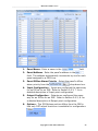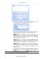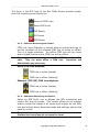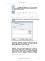
1
CS User Guide Version 3.9 For Windows XP Professional, Windows 7 Professional and Ultimate (32 or 64 Bit), Windows Server 2003, Server 2003 R2 and Server 2008 R2 W228 N727 Westmound Drive Waukesha WI 53186 262-522-1897 888-488-2623 ossi-usa.com CS Series User’s Guide Version 3.9.X __________________________________ Reference Guide Ver 3.9 _________________________________ Copyright Copyright © 1999 - 2013 OSSI, LLC All rights reserved. Information in this document is subject to change without notice. The software described in this document is furnished under a license agreement or nondisclosure agreement. The software may be used or copied only in accordance with the terms of those agreements. No part of this publication may be reproduced, stored in a retrieval system, or transmitted in any form or any means electronic or mechanical, including photocopying and recording for any purpose other than the purchaser’s use without the written permission of OSSI. OSSI, LLC W228 N727 Westmound Drive Waukesha WI 53186 U.S.A. Telephone: (262) 522-1897 Toll Free: (888) 488-2623 Fax: (262) 522-1872 Trademarks Intelli-Site® is registered in U.S. Patent & Trademark Office. All other registered and unregistered trademarks are the sole property of their respective owners. 2 Copyright © 1999- 2013 OSSI, LLC __________________________________ Reference Guide Ver 3.9 _________________________________ EULA BY OPENING THIS PACKAGE CONTAINING THE PROGRAM DISKETTES, THE COMPUTER SOFTWARE THEREIN, AND THE ACCOMPANYING USER DOCUMENTATION (COLLECTIVELY, THE “PROGRAM”), YOU ARE ACCEPTING AND AGREEING TO THE TERMS OF THIS AGREEMENT. THE PROGRAM IS LICENSED TO YOU AND NOT SOLD. IF YOU ARE NOT WILLING TO BE BOUND BY THE TERMS OF THIS AGREEMENT, YOU SHOULD PROMPTLY RETURN THE PACKAGE IN UNOPENED FORM, AND YOU WILL RECEIVE A REFUND OF YOUR MONEY. THIS AGREEMENT REPRESENTS THE ENTIRE AGREEMENT CONCERNING THE PROGRAM BETWEEN YOU AND ________________________ (“LICENSOR”), AND IT SUPERSEDES ANY PRIOR PROPOSAL, REPRESENTATION, OR UNDERSTANDING BETWEEN THE PARTIES. 1. License Grant. Licensor hereby grants to you, and you accept, a nonexclusive, nontransferable license to use the Software in machine-readable, object code form only, and only as authorized in this Agreement. The Software may be used only by the number of concurrent users for which you have paid license fees. If you have paid license fees for one user, then you may use the Software on a single computer owned, leased, or otherwise controlled by you; or in the event of the inoperability of that computer, on a back-up computer selected by you only during the extent of such inoperability. If you have paid license fees for two or more users, concurrent use on two or more computers or use in a local area network or other network is permitted. You agree that you shall solely use the Program for your internal needs. You agree that you will not assign, sublicense, transfer, pledge, lease, rent, or share your rights under this Agreement. You agree that you may not reverse assemble, reverse compile, or otherwise translate the Software. You may make one copy of the Software on a separate set of diskettes for the purpose of back-up in the event the program diskettes are damaged or destroyed. You may make one copy of the User Documentation for back-up purposes. Any such copies shall include Licensor’s copyright, trademark, and other proprietary notices. Except as expressly authorized in this Paragraph, no copies of the Program or any portions thereof may be made by you or any person under your authority or control. Copyright © 1999- 2013 OSSI, LLC 3 __________________________________ Reference Guide Ver 3.9 _________________________________ 2. Licensor’s Rights. You acknowledge and agree that the Program is the valuable property and trade secret of Licensor or Licensor’s third party licensors. You further acknowledge and agree that all rights, titles, and interests in and to the Program, including all associated intellectual and industrial property rights, are and shall remain with Licensor or Licensor’s third party licensors. 3. Third Party Beneficiary. You agree that Intelli-Site, Inc. (“Intelli-Site”) is a third party beneficiary of this Agreement. Though Intelli-Site has no obligations to you under this Agreement and you may not seek any claim against Intelli-Site as a result of this Agreement or the Program, Intelli-Site shall have the right to enforce this Agreement on its own behalf. 4. License Fees. The license fees paid by you are paid in consideration of the license granted to you under this Agreement. 5. Term. This Agreement is effective upon your opening of this package and shall continue until terminated. You may terminate this Agreement at any time by returning the Program and all copies thereof and extracts there-from to Licensor. Licensor may terminate this Agreement upon the breach by you of any term hereof. Upon such termination by Licensor, you agree to immediately return to Licensor the Program and all copies thereof and extracts therefrom. 4 Copyright © 1999- 2013 OSSI, LLC __________________________________ Reference Guide Ver 3.9 _________________________________ 6. Limited Warranty. Licensor warrants for a period of ninety (90) days from the date of commencement of this Agreement that the program diskettes in which the software is contained are free from defects in material and workmanship. Licensor further warrants for a period of one (1) year from the date of commencement of this Agreement the Program shall operate substantially in accordance with the functional specifications in the User Documentation. Licensor does not warrant that the functions contained in the Software will meet your requirements or that the operation of the Software will be uninterrupted or error-free. If during such one (1) year period, a reproducible defect in the Software appears, you may return the Program to Licensor for either a replacement or, if so selected by Licensor, refund of the license fee paid by you under this Agreement. You agree that the foregoing constitutes your sole and exclusive remedy for breach by Licensor of any warranties made under this Agreement. EXCEPT FOR THE WARRANTIES SET FORTH IN THIS PARAGRAPH, THE PROGRAM IS LICENSED “AS IS”, AND LICENSOR DISCLAIMS ANY AND ALL OTHER WARRANTIES, EXPRESS OR IMPLIED, INCLUDING, WITHOUT LIMITATION, ANY IMPLIED WARRANTIES OF MERCHANTABILITY OR FITNESS FOR A PARTICULAR PURPOSE. 7. Limitation of Liability. THE CUMULATIVE LIABILITY OF LICENSOR OR ANY OWNER OF ANY ELEMENT OF THE PROGRAM TO YOU OR ANY OTHER PARTY FOR ANY LOSS OR DAMAGES RESULTING FROM ANY CLAIMS, DEMANDS, OR ACTIONS ARISING OUT OF OR RELATING TO THIS AGREEMENT SHALL NOT EXCEED THE LICENSE FEES PAID TO LICENSOR FOR THE USE OF THE PROGRAM. IN NO EVENT SHALL LICENSOR OR ANY OWNER OF ANY ELEMENT OF THE PROGRAM BE LIABLE FOR ANY INDIRECT, INCIDENTAL, CONSEQUENTIAL, SPECIAL, OR EXEMPLARY DAMAGES OR LOST PROFITS, EVEN IF LICENSOR HAS BEEN ADVISED OF THE POSSIBILITY OF SUCH DAMAGES. SOME STATES DO NOT ALLOW THE LIMITATION OR EXCLUSION OF LIABILTY FOR INCIDENTAL OR CONSEQUENTIAL DAMAGES, SO THE ABOVE LIMITATION OR EXCLUSION MAY NOT APPLY TO YOU. 8. Severability. Should any term of this Agreement be declared void or unenforceable by any court of competent jurisdiction, such declaration shall have no effect on the remaining terms hereof. Copyright © 1999- 2013 OSSI, LLC 5 __________________________________ Reference Guide Ver 3.9 _________________________________ 9. No Waiver. The failure of either party to enforce any rights granted hereunder or to take any action against the other party in the event of any breach hereunder shall not be deemed a waiver by that party as to subsequent enforcement of its rights under this Agreement or subsequent actions in the event of future breaches. 10. U.S. Government Restricted Rights. The Program is provided with RESTRICTED RIGHTS. Use, duplication, or disclosure by the government of the United States is subject to restrictions as set forth in subparagraph (c)(1)(ii) of The Rights in Technical Data and Computer Software clause at DFARS 252.227-7013 or in subparagraphs (c)(1) and (2) of the Commercial Computer Software--Restricted Rights clause at 48 CFR 52.227-19, as applicable. Contractor/Manufacturer is Intelli-Site, Inc., 1805 Royal Lane, Suite 104, Dallas, Texas, 75229 U.S.A. You shall take all acts necessary to protect the rights of Licensor in the Program, including without limitation all acts described in the regulations referenced above. 11. Compliance with Laws. You represent, warrant and covenant that in using the Program it will comply with all applicable laws, regulations and government orders that may be issued or be in existence with respect thereto. You agree that you do not intend to and will not, directly or indirectly (a) export or transmit the Program, any related technical information and other data and materials to any country to which such export or transmission is restricted by any applicable U.S. regulation or statute, without the prior written consent, if required, of the Bureau of Export Administration of the U.S. Department of Commerce, or such other governmental entity as may have jurisdiction over such export or transmission, (b) provide the Program, any related technical information and other data and materials in any manner to any third party whom Customer knows or has reason to know will utilize such material in the design, development or production of nuclear, chemical or biological weapons or (c) provide the Program to any third party who has been prohibited from participating in U.S. export transactions by any federal agency of the U.S. government. 6 Copyright © 1999- 2013 OSSI, LLC __________________________________ Reference Guide Ver 3.9 _________________________________ 12. Governing Law. The rights and obligations of the parties under this Agreement shall not be governed by the provisions of the U.N. Convention on Contracts for the International Sale of Goods; instead, this Agreement shall be governed by and construed in accordance with the laws of the State of Texas, U.S.A., without reference to any conflicts of law provisions thereof. It is the express wish of the parties that this Agreement and all related documents be drawn up in English. C’est la volonté expresse des parties que la présente convention ainsi que les documents qui s’y rattachent soient rédigés en anglais. Copyright © 1999- 2013 OSSI, LLC 7 __________________________________ Reference Guide Ver 3.9 _________________________________ Table of Contents Copyright ................................................................................... 2 Trademarks .............................................................................. 2 EULA ............................................................................................. 3 Table of Contents ................................................................. 8 Section 1 – Introduction .................................................. 9 1.1 - Overview........................................................................... 9 1.2 - Key Features ................................................................... 9 1.3 - Optional Features ........................................................ 10 1.4 - Minimum System Requirements ........................... 11 1.5 - Additional Requirements .......................................... 11 1.6 - Display Settings ........................................................... 12 1.7 - Symbols and Conventions ....................................... 12 1.8 - Technical Support Assistance ................................. 13 Section 2 – Getting Started.......................................... 14 2.1 - Software Controls ....................................................... 14 2.2 - Software Components ............................................... 15 2.3 - Intelli-Site CS Installation ....................................... 15 2.3 – First Run......................................................................... 21 2.4 - Lead In Screen ............................................................. 23 2.5 - Application Menu Bar ................................................. 24 2.6 – Using the Wizard ........................................................ 25 2.7 – Driver Service and Server Shutdown ................. 49 Section 3 – Access Control Operation ................... 50 3.1 – Run Mode Screens ..................................................... 50 3.2 – The Information Manager ....................................... 57 Section 4 – Card Holder Management ................... 62 4.1 – Dossier and Card Management ............................. 62 4.2 - Card Holder List ........................................................... 63 4.2 - Using the Intelli-Site Database .............................. 65 4.3 - Card Database Tabs ................................................... 70 Section 5 – Documentation and Reports ............. 83 5.1 - Intelli-Site Reports ..................................................... 83 5.2 - Intelli-Site CS User Manual ..................................... 88 8 Copyright © 1999- 2013 OSSI, LLC __________________________________ Reference Guide Ver 3.9 _________________________________ Section 1 – Introduction This section describes the following: Overview Minimum System Requirements Symbols and Conventions Technical Support Assistance 1.1 - Overview The Intelli-Site CS software is a scalable, PC-based, system designed to integrate, control and manage Compass® electronic card access security components and selected (optional) digital video subsystems. Intelli-Site CS provides a powerful, userfriendly and simple-to-configure interface for small-to-medium electronic card access applications. 1.2 - Key Features Supports up to 24 Readers – The basic CS package (Part Number SFT-CS-01) supports 8 Intelligent Modules – Intelligent Reader Modules (IRM), Intelligent Input Modules (IIM) or Intelligent Output Modules (IOM) in any combination. The optional Reader Capacity Upgrade (Part Number SCO-CAP-UPG024) adds 4 more modules. Note: Each IRM can support up to 2 readers, 8 inputs and 4 outputs. A 24reader CS system has a total of 12 IRM modules. Easy-to-Use Wizard Programming – The installation package is easy to install with wizard-driven initial programming that includes panel configuration, communications, time zones, holidays, access levels, etc. Just add your card holders and go. Time and Area Access Control – CS allows for definition and assignment of authorized access to card holders by reader and by time period. Automatic Card Activation and Deactivation – Card holder rights activation and deactivation dates are automatically assigned. Copyright © 1999- 2013 OSSI, LLC 9 __________________________________ Reference Guide Ver 3.9 _________________________________ Card Holder Search – Card searches can be performed on any field in the card holder database. Easy data retrieval and manipulation can be accomplished through CS’s intuitive card holder interface. Multi-Identity – Intelli-Site CS can accommodate multiple cards assigned to individuals in the card holder database. Intuitive Graphical User Interface (GUI) – Intelli-Site CS users are presented with a very simple and easy-to-use control “point-and-click” interface. User controlled access – Intelli-Site CS uses its own user database to restrict and manage access to modules and functions. All access to the Intelli-Site CS system is controlled by password. Operating System – Intelli-Site CS runs on the Microsoft Windows 7 (Professional or Ultimate) in 32- or 64-bit environments (latest Service Packs). Two Workstation licenses are included with the basic package (one local and one remote). Database – Intelli-Site CS utilizes SQL 2008 R2 (included) for Card Management. Reports – Intelli-Site CS includes a built-in report generator to provide quick, pre-defined reports that include data specific to system operations. Network – Intelli-Site CS uses TCP/IP to provide an integrated, networked system. Intelli-Site CS easily integrates into existing networks, reducing overall installation and maintenance costs. 1.3 - Optional Features Photo Badge Module – The optional Photo Badge (Part Number SFT-CS-BDG) feature allows user to capture and store a digital picture image, graphically create and produce multiple badge designs to meet user-specific requirements as well as print photo ID badges. Work Station Module - Up to 3 remote Workstations may be added to Intelli-Site CS (Part Number SFT-CWS-001). Video Integration Capability – Intelli-Site CS may be integrated with a variety of digital video subsystems (Part Number SFT-VID-INT). Reserved for future release. Upgrade Path – Intelli-Site CS may be upgraded to Intelli-Site ES (Part Number SFT-ES-UPGRD) in order to unlock Intelli-Site’s full integration capabilities and capacities. 10 Copyright © 1999- 2013 OSSI, LLC __________________________________ Reference Guide Ver 3.9 _________________________________ 1.4 - Minimum System Requirements Operating System: Windows 7 (Professional or Ultimate) 32or 64-bit, Windows Server 2008 R2 (SP1), Windows Server 2003 R2 (SP1), Windows Server 2003 (SP2), Windows XP Professional (SP3) CPU (Processor): Intel CORE2 Duo 2.0GHz RAM (Memory): 2GB DDR2 800 MHz HDD (Disk Space): 200GB 7200RPM SATA-II 300 VGA (Video): 128MB VRAM @ 1280x1024, (32 bit color) Display: 17” VGA (Touch screen optional) Network & Protocols: 10/100/1000 network adapter with Windows TCP/IP Sound: Windows compatible sound card or USB sound adapter Input Devices: Mouse, keyboard, and 24X CD drive Note: For Windows Server 2008 R2 - Windows Media Player is required. This feature does not have to be enabled, but its components are required for the Workstation to run properly. The 'Desktop Experience' Windows Feature is automatically enabled by the CS Installer to ensure that this requirement is met. Note: For Windows 7 – Windows 7 automatically disables the sound card if no speakers are present. A cheap pair of headphones will suffice. 1.5 - Additional Requirements Video Badging (VB) Video Capture Card: Printer: Camera: Other: Osprey 101. Other video capture card devices may be used to display live video though were not tested in house and therefore are not supported Any printing device capable of feeding blank card accessories used in badging Any camera device including USB cameras. Blank card accessories Copyright © 1999- 2013 OSSI, LLC 11 __________________________________ _________________________________ Reference Guide Ver 3.9 1.6 - Display Settings Intelli-Site CS runs at a minimum screen setting of 1024 x 768 with small fonts for optimum viewing. The computer on which the software runs should be set to this screen resolution before Intelli-Site CS is started. 1.7 - Symbols and Conventions 1.7.2 - Notes, Tips, and Cautions Special comments, or areas that demand extra-close attention, are flagged throughout this manual with separating lines and a boldface keyword, as shown below. Note: When scanning a set of instructions, pay attention to information separated by lines, as shown here. It may save some time, or help avoid common mistakes. 1.7.3 - Fonts Words or phrases that appear as display buttons, keyboard keys, or Nodes, in either drop-down menus or dialogs, appear in bold. 1.7.4 - Display Buttons In general, when the manual refers to a graphic screen button, the button name and its graphic will be displayed. Text buttons will be displayed in bold font. For example: the Graphic Design Mode Main Application Bar Menu. 12 button located on the Copyright © 1999- 2013 OSSI, LLC __________________________________ Reference Guide Ver 3.9 _________________________________ 1.8 - Technical Support Assistance 1.8.1 – OSSI, LLC Headquarters W228 N727 Westmound Drive Waukesha WI 53186 262-522-1897 888-488-2623 1.8.2 - Technical Support Technical support is available via Telephone or Email. Contact Intelli-Site Technical Support 8:00 AM to 5:00 PM Central Standard time. If calling after hours, please leave a detailed voice mail message, and someone will return your call as soon as possible. Email: [email protected] Phone: 888-488-2623 When calling, please be at the computer prepared to provide the following information: 1. Product version number, found by selecting the 2. 3. 4. 5. 6. 7. About button from the Intelli-Site CS Menu Application Bar. Product License and SMA numbers used for registration. The type of computer being used including, operating system, processor type, speed, amount of memory, type of display, etc. Exact wording of any messages that appear on the screen. What was occurring when the problem was detected? What steps have been taken to reproduce the problem? It is highly recommended that the user execute a System Information Report and export that report to Adobe .pdf format for transmission to Intelli-Site technical support staff. Copyright © 1999- 2013 OSSI, LLC 13 __________________________________ Reference Guide Ver 3.9 _________________________________ Section 2 – Getting Started This section describes the basics of Intelli-Site CS. Software Controls Software Components Installation First Run The Lead-In Screen The Menu Bar Using the Wizard 2.1 - Software Controls Some of the procedures contained in this manual specifically mention using the mouse or keyboard to perform actions. As Intelli-Site CS systems can be configured to use touch-screen monitors in addition to a mouse and keyboard, when this manual text refers to "click " or “select” a button, substitute the action "touch.” 2.1.1 - Using the Mouse When a mouse is connected to the computer, it will operate the software with minimal use of the keyboard. This manual assumes that a standard two-button mouse will be used for all actions required by the Intelli-Site software. In many cases, there are keyboard shortcut keys that allow the operation of the software without using the mouse. Right+Click mouse action invokes the project design Wizard. 2.1.2 - Data Fields Intelli-Site Properties dialogs display data fields that permit the addition or modification of data. The data fields will display white when enabled, allowing the user to type in the field. 14 Copyright © 1999- 2013 OSSI, LLC __________________________________ Reference Guide Ver 3.9 _________________________________ 2.1.6 - Drop-Down Menus Drop-down menus are used with some data fields. The menus are enabled by clicking on a small down arrow at the far right of the field. Click the down arrow to display the menu selections. Click the desired menu selection to display it in the data field. 2.1.7 - Checkboxes Checkboxes are commonly used on Properties dialogs. They identify when a specific item has been turned on or off. Several checkboxes can be selected at one time. Click on the checkbox to select or deselect it. 2.2 - Software Components Intelli-Site CS is an object-oriented collection of linked software components that communicate using an industry standard, socket interface. Intelli-Site CS has four main software components: Intelli-Site CS Server – the Server is the “core” of the system. All communications to Workstations and field equipment are controlled through the Intelli-Site Server. Intelli-Site CS Workstation – the Workstation is the human interface to the system. All monitoring and system maintenance is performed via the Workstation. Intelli-Site CS Driver Service – Driver Service runs in the background to provide constant updates and status of attached Drivers. CS Drivers – Drivers allow Intelli-Site to communicate with the installed equipment, i.e., Compass Intelligent Modules and (optional) digital video subsystems. The hardware status and other information is converted to Intelli-Site-specific commands and passed to the Server. Likewise, Intelli-Site information and commands are passed to the Driver and converted to a control sequence that the hardware understands. 2.3 - Intelli-Site CS Installation There are two types of installations: ServerStation, and Workstation. The ServerStation selection will install the Intelli-Site Server and Workstation software along with all necessary drivers and the Driver Service software. The Workstation selection will only install the Intelli-Site Workstation used to remotely manage an Intelli-Site Server. Copyright © 1999- 2013 OSSI, LLC 15 __________________________________ Reference Guide Ver 3.9 _________________________________ Note: The CS basic package (Part Number SFT-CS-01) allows for up to two remote Workstations. Software Installation Step-By-Step The following section contains step-by-step procedures for installing Intelli-Site CS: 1. Verify that you hardware meets minimum system requirements as described in Section 1.4 2. Operating System Prerequisite: Ensure that Microsoft’s Windows .NET Framework 4 Client Profile has been installed. This software may be downloaded via “Windows Update” or directly from www.microsoft.com Note: For Windows XP Pro and Server 2003 users - ensure that Microsoft’s Windows .NET Framework 3.5 (SP1) has been installed. 16 3. Insert the software installation Compact Disc into the computer CD drive. After a few seconds, the OSSI welcome dialog will display momentarily. 4. The InstallShield® Wizard displays on the screen. Copyright © 1999- 2013 OSSI, LLC __________________________________ 5. Select 6. Select Reference Guide Ver 3.9 _________________________________ to continue the installation. to accept the License Agreement. Copyright © 1999- 2013 OSSI, LLC 17 __________________________________ 7. Reference Guide Ver 3.9 _________________________________ Enter your User Name and Company Name, then select . Note: You must enter both User and Company Name. 8. 18 Select to accept the default installation path (recommended) or select to choose a different location for your installation. Copyright © 1999- 2013 OSSI, LLC __________________________________ 9. Select (or Select select Reference Guide Ver 3.9 _________________________________ to install the software on the server computer, to install the remote Workstation) then . Note: The installation may take several minutes to complete. 10. Select to complete the installation. Your computer will shut-down and restart automatically if “Yes” is selected. Copyright © 1999- 2013 OSSI, LLC 19 __________________________________ Reference Guide Ver 3.9 _________________________________ 11. After restarting your computer, share the C: \Program Files\Intelli-Site, Inc.\Intelli-Site subdirectory. The share name may only contain alpha-numeric characters. See the example below: Ensure that permissions for the share you created are unrestricted. See the example below: Note: It is only necessary for you to create a share on the Server computer. 20 Copyright © 1999- 2013 OSSI, LLC __________________________________ Reference Guide Ver 3.9 _________________________________ 2.3 – First Run In order to Launch Intelli-Site CS, you must double-click the Intelli-Site Icon located on the Windows Desktop. Note: Initial start-up will differ, depending on whether you selected the ServerStation or Workstation option. 2.3.1- ServerStation First Run The Loader Program is launched by double-clicking the IntelliSite (Loader) icon on the Windows Desktop. The button is disabled in Intelli-Site CS. The will cancel start-up. button The product License Dialog will display. At this point, you may either enter a license number (obtained from technical support) or select . If you don’t enter a license number the software will run in demonstration mode, meaning the Server and Driver Service will shut down after 3 hours. They software can be restarted. Note: Your license number is based upon the Key Number displayed in the license dialog. Every computer will generate a unique Key Number. You need to supply your Key Number (and appropriate Purchase Order reference) to technical support in order to obtain a License Number. Save a screen shot of the above dialog and email it with the Purchase Order reference to [email protected]. Copyright © 1999- 2013 OSSI, LLC 21 __________________________________ Reference Guide Ver 3.9 _________________________________ The Intelli-Site CS Welcome Screen and Login Window will display: The default User name is master and the default Password is m. Note: The password is case-sensitive. For security reasons, the default Master password should be changed immediately. 2.3.1- Workstation First Run The first time you run the Loader Program on a remote Workstation, the Workstation Registry dialog will display: Note: There are only three options available in this dialog (all other fields and selections apply to Intelli-Site ES and above). 22 Copyright © 1999- 2013 OSSI, LLC __________________________________ Reference Guide Ver 3.9 _________________________________ Host Name – Enter the name of the computer where the ServerStation is installed. Signon Device – You may select one of three options: PC Keyboard – standard keyboard and mouse combination. T/S Keyboard – provides for a full touch screen keyboard layout. Randomized Keypad – provides a “scrambled” hexadecimal keypad for touch screen. Always print badges double sided – Necessary if you are going to use a double-sided ID Badge printer. Click the button to start the registration. A screen prompt will momentarily display to verify the Loader is working, followed by the Workstation Login dialog. 2.4 - Lead In Screen The Lead In Screen is the main working screen for Project monitoring and control. The Lead In Screen displays when the system starts, and has four main elements: Title Bar – the Title Bar is found at the top of the Workstation screen. It displays the Project currently being managed on the left and has window controls on the right. Operations Area – the Operations Area displays COM Lines and panel symbols which can be selected by the operator for display of component status and allow reader and output control. Information Manager–the Information Manager (IM) displays operational information for alarm display and management. Status Bar – the Status Bar is found at the bottom of the screen. It displays the Menu button on the left, which provides access to different modes of the system. On the right is status information including Operator Information, Shunts, Alarms, Events, date and time. Copyright © 1999- 2013 OSSI, LLC 23 __________________________________ Reference Guide Ver 3.9 _________________________________ Title Bar Operations Area Information Manager Status Bar 2.5 - Application Menu Bar The Application Menu Bar is displayed by clicking the Menu button, located in the bottom left corner of the Lead In Screen. The user can move the Menu Application bar by clicking in the blue title bar and dragging it. Close the Application Menu Bar by clicking the Exit button, clicking on the Menu button again, or by selecting a mode button. Run Mode – this mode is the graphic interface for the user to operate the system. Card Management Mode – is used for creating and maintaining the card holder database. Wizard Mode – is used for configuring and maintaining communications, panels, access control elements, remote workstations, priorities and system operator accounts. 24 Copyright © 1999- 2013 OSSI, LLC __________________________________ Reference Guide Ver 3.9 _________________________________ Graphic Design Mode – is used to create and program photo badges. Documentation and Reporting Mode – is used to view and print documentation and predefined system reports Save Project – enables you to configuration changes and, optionally, create a back-up copy of the current Project File. This option is only available while running in Graphic Design Mode. About – displays the About Workstation screen, which shows copyright information, EULA, version information, and license information. Log On/Off Mode – allows a user to log onto or off of a current Project session. The command does not exit the Workstation. Workstation Registration – allows a user to configure the Workstation Registration. This option will only be available if a user is logged-off. Exit Application Workstation. – allows a user to exit the 2.6 – Using the Wizard The CS configuration wizard provides a simplified, step-bystep method for entering all configuration parameters required to get your CS system up and running. Invoke the wizard by selecting the icon from the menu bar. The wizard configuration screen will open in the center of the display area as shown below: Copyright © 1999- 2013 OSSI, LLC 25 __________________________________ Reference Guide Ver 3.9 _________________________________ The navigation arrows, at the bottom of the wizard configuration screen allow you to “jump” between the various configuration tasks: HARDWARE – Allows you to define communications lines (up to 12), assign various modules (IRM, IIM or IOM) to each line, and configure the parameters for each of the modules assigned. TIME ZONES – Allows you to define Holiday Groups and Time Zones. ACCESS – Allows you to define Access Sets (Collections of Readers assigned to Time Zones). ADMIN – Allows you to define Users (System Administrators, Operators, etc.), configure remote Workstations, configure Priorities, and configure Digital Video Recording devices. 2.6.1- Defining COM Lines Before you can configure panels you must first define their communications. 26 Copyright © 1999- 2013 OSSI, LLC __________________________________ 1. Reference Guide Ver 3.9 Press the _________________________________ button to begin: Enter the name of the COM Line (default is COM Line n – where n is a sequential number from 1 to 12). Note: You can define up to 12 COM Lines 2. Select the symbol located to the right of the COM Line name field to open the COM Line Configuration dialog: Connection – Allows you to select Serial or TCP/IP (default). If you select Serial, you must then select the COM Port from the drop-down list provided. If you select TCP/IP, you must enter the IP address and the Port number. Setup – Allows you to select the RS-485 Chain Baud Rate and to adjust the Polling Rate. Click to save your settings. A notice dialog will display, reminding you that the Driver Service must be restarted in order to communicate with the panel(s) in this COM Line: Copyright © 1999- 2013 OSSI, LLC 27 __________________________________ Reference Guide Ver 3.9 _________________________________ Click on the restart notice dialog. A TCP/IP COM Line should look like this: A serial COM Line should look like this: 2.6.2- Adding New Panels Panels are defined and assigned to each of the COM Lines as follows. Add New Panel - Select the symbol located to the right of the COM Line symbol to open the Add New Panel dialog: You may add any one of three panel types by selecting the appropriate icon from the dialog: - Adds an Intelligent Reader Module and opens the IRM Configuration Screen. - Adds an Intelligent Input Module and opens the IIM Configuration Screen. 28 Copyright © 1999- 2013 OSSI, LLC __________________________________ Reference Guide Ver 3.9 _________________________________ - Adds an Intelligent Output Module and opens the IOM Configuration Screen. - If you’ve already added panels (of any type) you can add a new panel that is a duplicate. For example: You’ve added and configured an IRM panel (IRM Panel 1) and need another one that has the same configuration. You use the Copy of: function and select IRM Panel 1 from the drop-down list on the Add New Panel dialog. 2.6.3- Configuring an IRM Panel The IRM Panel configuration screen displays as soon as you select the symbol (and OK) from the Add New Panel dialog, or if you Right+Click on an existing IRM symbol (on the Main Wizard Screen) and select Edit. From this screen, you can configure the panel’s name, address, set-up style, panel offline alarm priority, door configuration, input and output configurations and options. You can also exercise panel control (auto-detect and reset) and downloads. Refer to the following figure: Copyright © 1999- 2013 OSSI, LLC 29 __________________________________ Reference Guide Ver 3.9 _________________________________ 1. Panel Name - Enter a name in the field. Tip: The name you enter should be as descriptive as possible, but not too long. 2. Panel Address - Enter the panel’s address in the field. The address automatically increments by one for each panel assigned to a COM Line. 3. Setup Style - Select the panel’s Setup Style from the drop-down box. Possible selections are: - This style allows for an unsupervised reader to be connected to each of the IRM’s two reader ports and used for two separate doors. This selection is normally used for “reader-in and REX-out” configurations. - This style allows for a supervised reader to be connected to each of the IRM’s two reader ports and used for two separate doors. This selection is normally used for “reader-in and REX-out” configurations. 30 Copyright © 1999- 2013 OSSI, LLC __________________________________ Reference Guide Ver 3.9 _________________________________ - This style allows for two readers to be used in a read-in/read-out configuration on a single door. 4. Panel Offline Alarm Priority - Select the panel’s offline alarm priority from the drop-down box. You can select None (default) or any of up to 16 available priorities. Note: Higher priority numbers take precedence over lower numbers, e.g.; Priority 16 has a higher priority than does Priority 4. Low, Medium and High priorities have been pre-defined, but can be edited later. Priority “None” will prevent the alarm from being reported in the Alarm Queue. 5. Door Configuration – The Door Configuration section of the IRM Configuration screen allows you to set all of the Door (reader) properties: If the selected Setup Style is Configuration will change as shown below: , the Door Entry/Exit APB Type – Select from the drop-down list to set Anti-Pass Back (APB) parameters for the entry reader as follows: - APB not enabled. - APB violation disallows entry. - APB violation is reported, but allows entry. - APB violation occurs if the same credential is presented to the reader within the Entry APB Time . Copyright © 1999- 2013 OSSI, LLC 31 __________________________________ Reference Guide Ver 3.9 _________________________________ Door Name – Enter a descriptive name for the reader here. When you enter this name, all of the reader’s associated input/output points (DPS input, REX input and Lock output) will automatically be renamed for you. Relock on DPS – Select this checkbox if the door is equipped with a magnetic lock. Unlock on REX – Select this checkbox if you want the door lock to release upon Request-to-Exit. Mode – Select the desired credential mode for this door as follows: - Access will be granted at this reader when a valid card is presented. - Access will be granted at this reader when a valid card is presented and a valid Personal Identification Code (PIN) is entered on the keypad. - Access will be granted at this reader when a valid PIN is entered on the keypad (keypad only). - Access will be granted when either a valid card is presented or a valid PIN is entered on the keypad. Unlock (sec) – Enter the duration of time the door will be unlocked (valid entry). Note: If a maglock is used, the lock will remain unlocked for this duration regardless of the door position. If a strike is used, the door lock will reengage as soon as the DPS senses that the door is physically opened. 32 DOTL (sec) – Enter the amount of time to allow a door to remain physically open (as detected by the DPS) after a valid entry before a Door Open Too Long (DOTL) is reported. This function allows the system to report a propped door condition. Warn (sec) – Enter the amount of time to allow a door to remain physically open (as detected by the DPS) after a valid entry before a Door Ajar (Warn) is reported. This is typically used with a local door ajar alarm sounder. Copyright © 1999- 2013 OSSI, LLC __________________________________ 6. Reference Guide Ver 3.9 _________________________________ Unlock Time zone – Select a Time zone from this list if you want the doors to automatically unlock/relock according to a pre-defined schedule. DOTL Alarm Priority – Select a priority level for DOTL Alarms (door propped). Forced Alarm Priority – Select a priority level for Door Forced (the door has been physically opened without a valid read). Advanced Door Configuration – The Advanced Door Configuration section of the IRM Configuration screen allows you to set additional (optional) Door (reader) properties. You access these features by selecting the button: Reader Mode Time zone – Select a Time zone from this drop-down list that will place the reader into the Time zone Active Mode while the selected Time zone is valid. For example: You want a card/PIN reader to switch from card read only to card plus PIN during a specific time of day. Time zone Active Mode – Select the mode that the reader will switch to during the Time zone selected in the Reader Mode Time zone drop-down list. Choices available are: Card Only, Card and PIN, PIN Only and Card or PIN. First In Time zone – Select the Time zone during which the First In Time zone is active. Copyright © 1999- 2013 OSSI, LLC 33 __________________________________ Reference Guide Ver 3.9 _________________________________ Note: The First In Time zone is used to “regulate” the Unlock Time zone. For example: A door may be programmed to automatically unlock from 08:00 – 17:00 (8AM – 5PM) Monday through Friday under normal circumstances. What if no one reports to work during that time period? You are left, then, with an empty building that is unlocked all day! In order to prevent this, you may add a First in Time zone that runs from 07:00 – 09:00 (7AM – 9AM) Monday through Friday. If a valid read is not detected at this reader during the First in Time zone period, the normal Unlock Time zone will not take effect, so the door will remain locked. The building is empty, after-all! 7. DPS – Select which input is connected to the Door Position Switch. REX – Select which input is connected to the Requestto-Exit. Lock – Select which output is connected to the Lock. Camera – If a camera is available, select appropriate camera from the drop-down list. Post-Alarm - Once the camera has been selected, this field becomes active. If you wish to record the video after to the Alarm select this checkbox and define the time duration in seconds. Pre-Alarm - Once the camera has been selected, this field becomes active. If you wish to record the video before the Alarm select this checkbox and define the time duration in seconds. Input Configuration – The Input Configuration section of the IRM Configuration screen allows you to set all of the Input properties: Reminder: 34 the Name – Enter a descriptive name for the input here. A reader’s associated input/output points (DPS input, REX input and Lock output) are automatically renamed when the reader name is changed. Copyright © 1999- 2013 OSSI, LLC __________________________________ Reference Guide Ver 3.9 _________________________________ N/C Checkbox – If you select this checkbox the input’s “normal” state will be set to closed (i.e., an open will cause an alarm). States – Select the EOL (End Of Line) supervision method for this input as follows: - Two-state, or unsupervised inputs Normal and Alarm conditions. Example: monitor - Three-state, supervised inputs monitor Normal, Alarm, and Short or Open conditions. Example: - Four-state, supervised inputs monitor Normal, Alarm, Short, and Open conditions. Example: Disable Time zone – Select a Time zone from this dropdown list during which the input is disabled (will not report changes of state). Copyright © 1999- 2013 OSSI, LLC 35 __________________________________ Reference Guide Ver 3.9 _________________________________ Linked Output – Select an Output point from the dropdown list that will go active whenever the input goes into alarm. Note: You can only link to Outputs on the same panel. 8. Turn Off on Disable – If this box is checked, the Output linked to the Input is turned off when the corresponding Input is disabled. Alarm Priority – Select from the drop-down list the Priority level for this Input. Delay Time zone – During the selected Time zone (from the drop-down list) the alarm report from this Input will be delayed for the amount of time (in seconds) entered into the corresponding Delay (sec) field. Output Configuration – The Output Configuration section of the IRM Configuration screen allows you to set all of the Output properties: Reminder: A reader’s associated input/output points (DPS input, REX input and Lock output) are automatically renamed when the reader name is changed. 9. 36 Name – Enter a descriptive name for the Output here. Operate Time zone – Select a Time zone from the dropdown list during which the corresponding Output will be On (energized). Options – The Options Configuration section of the IRM Configuration screen allows you to enable Daylight Saving Adjustment and set the Long Access Time parameter: Copyright © 1999- 2013 OSSI, LLC __________________________________ Reference Guide Ver 3.9 _________________________________ DST Adjust – Select this checkbox to enable the panel to automatically adjust for Daylight Saving time change. Long Access Time – Enter the time (in seconds) for long access. This will, for selected card holders, cause the door to unlock for the long access time (as opposed to the normal unlock time). 10. Panel Control – The Panel Control section of the IRM Configuration screen allows you to Auto-Detect a panel and/or Reset a panel. Auto Detect – Select the button to Automatically detect and set the panel’s RTU (Remote Transceiver Unit) identification: Reset – Select this to Reset a panel’s previously-set RTU ID: 11. Download – The Download section of the IRM Configuration screen allows you to download configuration settings to the panel. Copyright © 1999- 2013 OSSI, LLC 37 __________________________________ Reference Guide Ver 3.9 _________________________________ – Select this button to download settings, such as Time zones, I/O supervision, reader configurations, etc. to the panel. - Select this button to download card holder information to the panel. - Select this button to download both card holder information and settings to the panel. firmware. - Select this button to download the panel’s 2.6.4- Configuring an IIM Panel The IIM Panel configuration screen displays as soon as you select the symbol from the Add New Panel dialog, or if you Right+Click on an existing IIM symbol (on the Main Wizard Screen) and select Edit. From this screen, you can configure the panel’s name, address, panel offline alarm priority, input and output configurations and options. You can also exercise panel control (auto-detect and reset) and downloads. Refer to the following figure: 38 Copyright © 1999- 2013 OSSI, LLC __________________________________ Reference Guide Ver 3.9 _________________________________ 1. Panel Name - Enter a name in the 2. Panel Address - Enter the panel’s address in the field. The address automatically increments by one for each panel assigned to a COM Line. 3. Panel Offline Alarm Priority - Select the panel’s offline alarm priority from the drop-down box. 4. Input Configuration – Inputs are configured the same way for an IIM as for an IRM. Refer to Section 2.6.3, 7. for a detailed description of Input point configuration. 5. Output Configurtion – Outputs are configured the same way for an IIM as for an IRM. Refer to Section 2.6.3, 8. for a detailed description of Output point configuration. 6. Options – The IIM Options section differs from the IRM in that only DST adjust check box is available for configuration: Copyright © 1999- 2013 OSSI, LLC field. 39 __________________________________ Reference Guide Ver 3.9 _________________________________ 7. Panel Control – Panel Control is configured the same way for an IIM as for an IRM. Refer to Section 2.6.3, 10. for a detailed description of Panel Control. 8. Download - The IIM Download section differs from the IRM in that only Settings and Firmware download options are available: 2.6.5- Configuring an IOM Panel The IOM Panel configuration screen displays as soon as you select the symbol from the Add New Panel dialog, or if you Right+Click on an existing IOM symbol (on the Main Wizard Screen) and select Edit. From this screen, you can configure the panel’s name, address, panel offline alarm priority, input and output configurations and options. You can also exercise panel control (auto-detect and reset) and downloads. Refer to the following figure: 40 Copyright © 1999- 2013 OSSI, LLC __________________________________ Reference Guide Ver 3.9 _________________________________ 1. Panel Name - Enter a name in the field. 2. Panel Address - Enter the panel’s address in the field. The address automatically increments by one for each panel assigned to a COM Line. 3. Panel Offline Alarm Priority - Select the panel’s offline alarm priority from the drop-down box. 4. Input Configuration – Inputs are configured the same way for an IIM as for an IRM. Refer to Section 2.6.3, 7. for a detailed description of Input point configuration. 5. Output Configurtion – Outputs are configured the same way for an IIM as for an IRM. Refer to Section 2.6.3, 8. for a detailed description of Output point configuration. 6. Options – The IOM Options section differs from the IRM in that only DST adjust check box is available for configuration: 7. Panel Control – Panel Control is configured the same way for an IOM as for an IRM. Refer to Section 2.6.3, 10. for a detailed description of Panel Control. 8. Download - The IOM Download section differs from the IRM in that only Settings and Firmware download options are available: 2.6.6 - Configuring Time Zones The Time Zones configuration screen displays as soon as you select the symbol from the Main Wizard Screen. From this screen, you can configure Holidays and Time zones. Refer to the following figure: Copyright © 1999- 2013 OSSI, LLC 41 __________________________________ 1. Reference Guide Ver 3.9 _________________________________ Holidays – To configure a Holiday select the button in the Holiday section of the screen and enter the date (mm/dd/yyyy) or select the date from the calendar display by selecting the button: Select to add the Holiday to the list. You can edit an existing Holiday by selecting the holiday in the list and clicking the button. You can remove a holiday from the list by selecting the holiday in the list and clicking the button. 42 Copyright © 1999- 2013 OSSI, LLC __________________________________ 2. Reference Guide Ver 3.9 _________________________________ Time Zones – A Time Zone is comprised of a collection of time intervals (Time Lines), days-of-the-week and a holiday flag. To add a new Time Zone, click the button (located below the Time Zones list. This selection enables the configuration options under the Settings area. Give the Time Zone a descriptive name (enter this in the Name field), then click the (button located under the Settings section). This selection enables the Time Lines options. Create at least one Time Line by entering Start and End times, and check-boxes for desired days of the week (add the Holiday flag check box – if you want the Time Line to be valid on Holidays) and click the button located below the days-of-the-week check-boxes. This selection saves the Time Line to the Time Line list. You can add more Time Lines as required. Note: Time Lines cannot span midnight. If you need a Time Zone that is valid from, say 17:30 to 01:30 (5:30PM – 1:30AM) you would need to define two, separate Time Lines: One from 17:30 – 23:59, and another one from 00:00 – 01:30. After you enter all Time Lines to define a particular Time Zone, you have to select the button located below the Time Zone list in order to complete the configuration. Copyright © 1999- 2013 OSSI, LLC 43 __________________________________ Reference Guide Ver 3.9 _________________________________ 2.6.7 - Configuring Access The Access configuration screen displays as soon as you select the symbol from the Main Wizard Screen. From this screen, you can configure Access Sets. Refer to the following figure: 44 1. Access Sets – To configure an Access Set select the button located below the Access Set list. 2. Name – Enter a descriptive name in the Name field. 3. Time Zone – Select a Time Zone from the drop-down box. 4. Select Door(s) – Select at least one door from the Door List. If multiple doors are required, you can select multiple doors by left-click on each door while holding down the Shift key. Select the button to add the Access Set to the list. 5. Edit/Delete – You can edit or delete Access Sets by selecting a previously-defined Access Set and selecting the button to edit, or the button to remove the Access Set. Copyright © 1999- 2013 OSSI, LLC __________________________________ Reference Guide Ver 3.9 _________________________________ 2.6.8 - Configuring Admin The Admin configuration screen displays as soon as you select the symbol from the Main Wizard Screen. From this screen, you can configure Users, Remote Workstations, Priorities and DVR. Refer to the following figure: 1. Users – The Users section of the Admin screen allows you to add and edit system users: Copyright © 1999- 2013 OSSI, LLC 45 __________________________________ Reference Guide Ver 3.9 _________________________________ To create a new User, select the action enables the Settings section: button. This Enter a Username and Password in the fields as shown above, then select a Type from the drop-down box: - The Operator type is restricted to runmode functions such as: Alarm Monitoring, Locking and Unlocking Doors, Running Reports and Operating input/output points screens. - The Supervisor type may add/modify and delete card holder information, download card records and perform all of the functions of an Operator type. - The Administrator type may configure the system using the Wizard, design photo badge templates and perform all of the functions of a Supervisor and Operator type. You may edit or delete previously-configured Users by selecting the User in the User List, then selecting the button to edit or the button to delete. Note: The software will not allow you to delete all users. 46 Copyright © 1999- 2013 OSSI, LLC __________________________________ 2. Reference Guide Ver 3.9 _________________________________ Remote Workstations – The Remote Workstations section of the Admin screen allows you to define and configure Remote Workstations and set the share path: To create a new Remote Workstation, select the button. This action enables the Settings section: Enter the name of the Remote Workstation computer in the Computer Name field. Note: This name must match the computer’s network name exactly. Reminder: You may edit or delete previously-configured Remote Workstations by selecting the Remote Workstation in the Remote Workstation List, then selecting the button to edit or the button to delete. Select the Network Share Name using the button. You must share the Intelli-Site subfolder on the ServerStation computer. See Section 2.3 for detailed information on sharing. 3. Priorities – The Priorities section of the Admin screen allows you to customize the characteristics of the 16 available Alarm Priorities. Alarm Priorities, when assigned to an alarm point, determine the alarm’s behavior with respect to: Position in the Alarm Queue Copyright © 1999- 2013 OSSI, LLC 47 __________________________________ Reference Guide Ver 3.9 _________________________________ Text color Notification Sound type and play characteristics Behavior of the Workstation when it is running in the background Refer to the figure below: To edit a Priority you select the Priority in the Priorities list and click the button. This action enables the Settings section: Enter the name of the Priority in the Name field. Select the text color from the Color in Queue drop-down list. Select the acknowledge-required sound from the Ack Req. Sound drop-down list. Check the Play Continuously box if you want the sound to play until the alarm is acknowledged. If you leave this unchecked, the sound will play only once. Check the Bring WS to Front box if you want the Workstation application to automatically come forward (if running in the background) when an alarm occurs. 48 Copyright © 1999- 2013 OSSI, LLC __________________________________ Reminder: Reference Guide Ver 3.9 Select the priority or the _________________________________ button to save your changes to the button to cancel the changes. You cannot create new Priorities, only modify the 16 available. 2.7 – Driver Service and Server Shutdown The CS configuration wizard takes care of Driver configuration, so this section will simply describer Driver Service and Server shutdown procedures. To shutdown the Driver Service program, locate the Driver Service icon in the system tray right+click. Select Exit from the dialog. and To shutdown the Server program, located the Server icon in the system tray and right+click. Select Exit from the dialog, then select Immediate Shutdown from the pop-up dialog. Copyright © 1999- 2013 OSSI, LLC 49 __________________________________ Reference Guide Ver 3.9 _________________________________ Section 3 – Access Control Operation This section discusses Access Control Operation and provides details on Alarm monitoring operations. Run Mode Screens Information Manager (IM) Queue Control Monitor Control Shunt Control Operator Messages 3.1 – Run Mode Screens The Run Mode Screen is configured by using the Wizard Mode. Once this configuration is complete, the Run Mode Screen provides a simple and intuitive Graphical User Interface for you to use to monitor and control the various COM Lines and panels. 50 Copyright © 1999- 2013 OSSI, LLC __________________________________ Reference Guide Ver 3.9 _________________________________ The Icons in the GUI Area of the Run Mode Screen provide simple, one-click monitoring and control for: Ethernet COM Lines Serial COM Lines IRM Panels IIM Panels IOM Panels 3.1.1 - COM Line Monitoring and Control COM Line icons (Ethernet or Serial) allow an authorized user to set the condition of the selected COM line to online or offline. This is a toggle selection: An offline COM Line will go online when clicked, and an online COM Line will go offline. Note: Operator-type users can only set an offline COM Line to its online state. They can never offline a COM Line. Supervisor and Administrator-type users may. Serial COM Line displays: - COM Line is online (steady) - COM Line is offline (flashing) Ethernet (TCP/IP) COM Line displays: - COM Line is online (steady) - COM Line is offline (flashing) 3.1.2 – IRM Panel Monitoring and Control Select an IRM Panel icon to display the IRM monitoring and control GUI pop-up screen. This screen allows you to monitor and/or control the states of all inputs and outputs on the IRM, lock and unlock doors, download cards and settings and set the panel to virtual. Note: Only Administrator-type users can download. Operator-level users may not set a panel to virtual. Copyright © 1999- 2013 OSSI, LLC 51 __________________________________ Reference Guide Ver 3.9 _________________________________ Inputs – There are eight inputs available on the IRM. Up to four may be reserved for door control: Door Position Monitor (DPS) and Request-to-Exit (REX). The last input is reserved for Panel Tamper. - Indicates that the input is enabled and in its normal state. - Indicates enabled and in its alarm state. that the input is - (Steady Yellow) Indicates that the input is enabled and in its trouble “open” state. - (Flashing Yellow/Red) Indicates that the input is enabled and in its trouble “shorted” state. 52 Copyright © 1999- 2013 OSSI, LLC __________________________________ disabled. input. Reference Guide Ver 3.9 Select the _________________________________ - Indicates that the input has been checkbox to disable/enable an Outputs – There are four outputs on an IRM. Up to two are typically reserved for door control (door lock outputs). - Indicates that the output is enabled and in its normal (off) state. - Indicates that the output is enabled and in its active (on) state. Set the state of an output by selecting its button. disabled. output. Select the - Indicates that the output is checkbox to disable/enable an Readers – Two readers are available on each IRM. secure. - Indicates that the reader is - Indicates that the reader is unlocked. Set the state of a reader by selecting its button. Alarms - The IRM is capable of reporting four different types of alarms: Panel Status – This alarm goes active when the panel is offline (communication failure). Auto-downloaded – This alarm goes active when the panel has forced an automatic download of data from the host. Usually this indicates that the panel has erased its internal memory and requires new data. Copyright © 1999- 2013 OSSI, LLC 53 __________________________________ Reference Guide Ver 3.9 _________________________________ Forced – This alarm indicates that the door has been forced open. There are two alarms – one for each of the two doors. DOTL – This alarm indicates that the door has been propped open. There are two alarms – one for each of the two doors. normal state. active “alarm” state. - Indicates that the alarm is in its - Indicates that the alarm is in its Panel Control – There are five controls available on the IRM screen: - Select this button to set the panel to its virtual state. - Select this button to set the panel to its normal state. - Select this button to download panel settings. - Select this button to download card records to the panel. Reminder: Virtualize is only available to Supervisor and Administratortype users. Download Settings and Download Cards is only available to Administrator-type users. When a panel has been set to its virtual state, it no longer communicates state changes to the host or accepts any commands from the user interface. The panel display changes to indicate the virtual condition: 54 Copyright © 1999- 2013 OSSI, LLC __________________________________ Reference Guide Ver 3.9 _________________________________ 3.1.3 – IIM Panel Monitoring and Control Select an IIM Panel icon to display the IIM monitoring and control GUI pop-up screen. This screen allows you to monitor and/or control the states of all inputs and outputs on the IIM, download settings and set the panel to virtual. Copyright © 1999- 2013 OSSI, LLC 55 __________________________________ Reference Guide Ver 3.9 _________________________________ Inputs – There are sixteen inputs available on the IIM. The last input is reserved for Panel Tamper. Input display and disable control is identical to the IRM. Outputs – There are four outputs on an IIM. and disable control is identical to the IRM. Output display Alarms - The IIM is capable of reporting a Panel Status alarm. The Panel Status alarm is identical to the IRM. Panel Control – There are three controls available on the IRM screen: - Select this button to set the panel to its virtual state. - Select this button to set the panel to its normal state. - Select this button to download panel settings. 3.1.3 – IOM Panel Monitoring and Control Select an IOM Panel icon to display the IOM monitoring and control GUI pop-up screen. This screen allows you to monitor and/or control the states of all inputs and outputs on the IOM, download settings and set the panel to virtual. 56 Copyright © 1999- 2013 OSSI, LLC __________________________________ Reference Guide Ver 3.9 _________________________________ Inputs – There are four inputs available on the IOM. display and disable control is identical to the IRM. Input Outputs – There are sixteen outputs on an IOM. Output display and disable control is identical to the IRM. Alarms - The IOM is capable of reporting a Panel Status alarm. The Panel Status alarm is identical to the IRM. Panel Control – There are three controls available on the IRM screen: - Select this button to set the panel to its virtual state. - Select this button to set the panel to its normal state. - Select this button to download panel settings. 3.2 – The Information Manager Intelli-Site allows the user to monitor system activity and alarm conditions on a real-time basis through the Information Manager (IM). The IM is typically displayed in all operating modes, allowing alarms to be monitored while using other system features. The IM displays in the bottom portion of the screen and provides four tabs to view and respond to monitoring activity. They are: Queue Control Monitor Control Shunt Control Operator Messages The Tabs on the bottom of the window will toggle between the four IM queues. The IM window may be resized. Copyright © 1999- 2013 OSSI, LLC 57 __________________________________ Reference Guide Ver 3.9 _________________________________ 3.2.1 - Queue Control Click the Information Manager window Queue Control (Alarm Status) tab to display all of the alarms that have been triggered and acknowledged. The Queue Control tab is the default display for this window. Conditions may also be displayed that are not alarm conditions, but are events that need to be displayed, like presenting an access card to a reader for door access. When the Queue Control tab is selected, the Control buttons display. The buttons are used to select, acknowledge and clear events from the queue. An acknowledge/Clear Dialog can be displayed by clicking the right mouse button on the alarm text in the queue. This dialog performs the same function as the control buttons, but provides an area to input instructions or comments (for example, as to condition resolutions). Priorities (as configured in the Wizard) determine how, and in what order, the information is displayed. After selecting an event from the queue display, the Control buttons are used to perform the designated action. Alarm conditions will continuously sound (loop) an audible alarm (if configured) until acknowledged. Queue Control Buttons - The Select Event button will open the selected event’s dialog window. The Clear button on the dialog window will clear the event. The Ack Event button acknowledges the event and silences an audible alert (if configured to sound alert), but does not display a dialog. The Scroll Up button moves the highlight bar up the list of events in the Queue Control window. The Scroll Down button moves the highlight bar down the list of events in the Queue Control window. 58 Copyright © 1999- 2013 OSSI, LLC __________________________________ Reference Guide Ver 3.9 _________________________________ The Ack All Events button acknowledges all unacknowledged events and silences audible alerts in the Queue Control window. The Clear All Events button clears all events in the Queue Control window and silences any associated audible alerts. The Acknowledge/Clear dialog will display when the right mouse button is clicked on a highlighted event entry. A window similar to the following will display. Acknowledge/Clear Dialog - The dialog will show the Alarm Description, Operator Instructions, Response Comments along with the Ack Alarm, Clear and Close buttons. An event must be acknowledged before it can be cleared. For card access violations, two additional buttons are displayed: View Card Record and Forgive Antipassback Violation. View Card Record allows you to open the card holder’s record and (if authorized) add a new record or edit an existing record. Forgive Antipassback Violation allows you to reset a cardholder’s passback settings so that the cardholder is given a second attempt to gain entry or exit. Copyright © 1999- 2013 OSSI, LLC 59 __________________________________ Reference Guide Ver 3.9 _________________________________ The Queue Control data displays in columns, which can be resized to suit individual users. The column data is sorted by clicking on the column heading. Select the border between column headings to make the columns wider or narrower. Scroll bars automatically display when necessary to allow for scrolling up and down through the list or left and right if column data extends past the display boundaries. Queue Control Data - Alarm Description – displays the text description of the alarm (event). Event Status – displays the status of the condition: for example, “Door is Open”. Priority – displays the priority assigned to the event (alarm). Date – displays the date of the occurrence. Time – displays the time of day of the occurrence. Counter – displays the number of times the alarm has been activated. Card No – displays the card number of the card causing the alarm, assuming the alarm condition is initiated from a card reader. Intelli-Site Server – displays the name of the Project connected to the point displaying the alarm condition. When a system device is configured to display in the Queue Control on a high or low condition, an audible alarm sounds (if configured) and a text message displays in the Queue Control window. Responding to Events - A Red Speaker icon displays at the beginning of the event alert in the Queue Control window. The red speaker represents an event that has not been acknowledged by the operator. When an event is acknowledged, the red speaker changes to a Green Check Mark icon. The event can then be cleared from the queue. Managing the Queue (Step-by-step) 1. At the Queue Control, select the desired alarm to highlight it 2. Click the Ack button to acknowledge the event’s audible alert. The audible alert stops and the icon displays. 60 Copyright © 1999- 2013 OSSI, LLC __________________________________ Reference Guide Ver 3.9 _________________________________ 3. Click the Select button to open the Acknowledgement/Clear dialog that is used to display special instructions and/or operator comments. 4. At the event dialog Comments field enter any necessary comments. 5. Click one of the dialog buttons to complete the action. To acknowledge all audible events, click the Ack/All button. 3.2.2 - Monitor Control The Monitor Control tab displays a continuous list of activity. Items listed in this queue are viewed but cannot be selected or acted on. 3.2.3 - Shunt Control The Shunt Control tab is reserved for future use. 3.2.4 - Operator Messages The Operator Messages tab displays all messages to the User logged to a Project. Items listed in this queue are view only and cannot be selected, or acted on. Copyright © 1999- 2013 OSSI, LLC 61 __________________________________ _________________________________ Reference Guide Ver 3.9 Section 4 – Card Holder Management This chapter describes managing cardholder information and badges including: Dossier and Card Management Using the Intelli-Site Database Database Tabs 4.1 – Dossier and Card Management The database stores data used for generating employee badges. To display the database data, select the Card Management Mode button from the menu bar. Mode control screen will display: The Card Management A Card Holder Dossier is selected from the list on the left side of the screen. The data for the selected Card Holder is displayed on the data tabs to the right. 62 Copyright © 1999- 2013 OSSI, LLC __________________________________ Reference Guide Ver 3.9 _________________________________ Four data tabs are used to manage the database and badges: CardData, Vehicle, Access, Badge, and Activity. Click on a tab to access each tab’s fields and display the entries for the selected tab. Note: The Vehicle Data tab is not available to you until you have entered at least one card holder record. 4.2 - Card Holder List The Card Holder List, located on the left side of the screen, displays a shortened version of Cardlist data. The default columns displayed in this window are the user’s last and first name. The column titles (Lastname and Firstname in the example below) are the names provided from the Cardlist Database. Copyright © 1999- 2013 OSSI, LLC 63 __________________________________ Reference Guide Ver 3.9 _________________________________ Directly below the Dossier Are is the Card Area. This area displays the actual card numbers (and their assigned site codes) assigned to each card holder in the Dossier Area. The bottom of the screen displays the highlighted record’s number and the arrows that allow moving through the list one record at a time or to the beginning and end quickly. The slide bar allows moving through the displayed list vertically and horizontally. The Refresh button will do a complete screen refresh and sets the first record active. The Reset button resets the list display to the original default display. The table can be sorted by column. To sort the list by column, double-click the column heading. The entire list will sort by the contents of the selected column, numerically and alphabetically, as needed. For example, click the Last Name column heading to sort the list alphabetically by card holder last name. The bottom of the display shows the current SQL select statement. You can modify this statement manually. Both the dossier and card table areas allow certain right-click functionality within the grid. Choose a record, or multiple records, right-click and a pop-up menu will appear. If multiple records are selected the selected action will apply to all records that are highlighted. In the Dossier area: Download Card(s) – downloads cards selected from the table. Export Photo(s) – allows a user to export the photos associated with a card record in the form of a .jpeg. Delete Dossier(s) – allows a user to delete all the card records chosen from the table. Select All – selects all records within the database. In the Card area: 64 Copyright © 1999- 2013 OSSI, LLC __________________________________ Reference Guide Ver 3.9 _________________________________ Download Card(s) – downloads cards selected from the table. Assign Access rights… – opens the Access tab to allow you to assign access rights to the selected card(s): Remove Access rights… – opens the Access tab to allow you to remove access rights from the selected card(s): Export Photo(s) – allows a user to export the photos associated with a card record in the form of .jpeg images. 4.2 - Using the Intelli-Site Database The following section describes how to enter a new card holder (Dossier) record and the various data tabs associated with each dossier. From this screen, data is entered and maintained: The buttons on the bottom of the data tabs allow you to: Copyright © 1999- 2013 OSSI, LLC 65 __________________________________ Reference Guide Ver 3.9 _________________________________ Add – clears the entry screen and allows input of new information to the tab. Edit – unlocks the entries displayed on the tab for making necessary changes. Delete – deletes the record from the database. An acknowledgement dialog will display to verify the record has been deleted. Search – allows a specific record or group of records to be located. Save – saves the record to the database. Cancel – cancels the current entry. Download – downloads the data for the current dossier record to the associated IRM panels. Import Cards… - allows you to import cardholder data from any delimited format. Add Card Range – add a range of cards starting with a specified number and how many to add. Bulk Modify Selected Records – modify one or more dossier parameter(s) when multiple records are selected via the grid. Download when saved – will automatically download new card settings to applicable IRM panels when changes are saved. 4.2.1 - Add Card Holder Data Use the following procedure to add new dossiers: 1. At the Data tab, click the Add button. The data fields clear, the color changes to white and is ready for new data to be input. The default Active and Deactivate dates display. 2. Complete the Data tab fields as necessary. If data is not entered into fields, those fields will remain blank when the database record is saved. Note: You can add the first card number at this time, or you can go back to the dossier at a later date and add multiple card numbers. 3. Click the Save button to save the cardholder information. 4. At the cardholder list, click the Refresh button to display the new database record. 66 Copyright © 1999- 2013 OSSI, LLC __________________________________ Reference Guide Ver 3.9 _________________________________ 4.2.2 - Modify Card Holder Data 1. Click to highlight Cardholder Name from the list. Click to select the Edit button. 2. Click on the “field” to edit and type the changes. 3. Click to select the Save button to save the changes to the cardholder file. The new Cardholder data displays in the Cardholder list and on the Data tab to the right. 4.2.3 - Delete Card Holder Data 1. Click to highlight Cardholder Name from the list. 2. Click to select the Delete button. A popup window will display to verify deletion of the record. 3. Click Yes to delete the record. Note: The program will verify the record is queued for deletion from the system through a voice message. 4.2.4 - Importing Card Data This feature allows you to import Cardholder data from any properlyformatted delimited file. You choose the delimeter character and text qualifier. If a given card record being imported via the 'Import Cards' routine contains a .jpg file in the same folder as the .csv file, the photo is automatically imported. The files should take the form of "cardnumber">.jpg. A new dossier will be created for each cardnumber entry in the import file. You may end up with multiple entries for the same individual (as each dossier may be assigned multiple cards). Use the Merge Dossiers function to eliminate duplicate data whilst keeping the required cards. Note: Cardholder data to be imported must match the Intelli-Siteacceptable database schema. Refer to the table below for the SQL database schema required. Copyright © 1999- 2013 OSSI, LLC 67 __________________________________ Reference Guide Ver 3.9 Field Name FirstName LastName MiddleInitial Title Department WorkPhone WorkExtension Address City StateOrProvince PostalCode Photo Signature Company Department CardEmbossNumber GrantLongAccessTime CardNumber SiteCode CardFormat PinNumber ActivateDate DeactivateDate CardType VehicleMake VehicleModel PrimaryColor SecondaryColor State Tag Sticker Year 68 _________________________________ Type Len nvarchar 50 nvarchar 50 nvarchar 3 nvarchar 50 nvarchar 50 nvarchar 30 nvarchar 20 nvarchar 255 nvarchar 50 nvarchar 20 nvarchar 20 image image nvarchar 50 nvarchar 50 nvarchar 50 bit bigint bigint tinyint nvarchar 50 smalldatetime smalldatetime tinyint varchar 50 varchar 50 varchar 50 varchar 50 varchar 50 varchar 50 varchar 50 varchar 4 Copyright © 1999- 2013 OSSI, LLC null null null null null null null null null null null null null null null null null null notnull notnull notnull null notnull notnull null notnull notnull notnull notnull notnull notnull notnull notnull __________________________________ Reference Guide Ver 3.9 _________________________________ 4.2.5 - Bulk Modify Card Holder Data 1. Click to highlight multiple Cardholder Names from the list or run a query to select multiple cardholders. Click to select the Bulk Modify Selected Records button. 2. Click on the “field” to edit and type the changes. 3. Click to select the Save button to save the changes to the cardholder file. The new Cardholder data displays in the Cardholder list and on the Data tab to the right. All records selected in Step 1 (above) will be modified. 4.2.6 - Searching the Database Intelli-Site CS allows you to choose from two search utilities for querying the database: Structured Query Language (SQL) and Simple Field-Parameter Search. The SQL Search entry box is located under the Card Holder list. The SQL feature is accessed using the Query button. The Simple Field-Parameter Search feature is accessed through the Search button under the Data tab. 1. Click the Search button located at the bottom of the screen. The data fields are unlocked and any displayed data is cleared. The Save button changes to a Query button. 2. Enter “Search Parameters” into one or more data fieldsThe fields are not case sensitive. Copyright © 1999- 2013 OSSI, LLC 69 __________________________________ Reference Guide Ver 3.9 _________________________________ 3. Select the button to start the search. The search results will display in the Dossier List and Cardholder’s Data Tab on the right. The entry box below the Card Holder List s displays the equivalent SQL syntax of the simple search feature. The first displayed database record will display on the data tab after the search results are displayed. To Perform a SQL Database Search: Type the SQL query for the search and click the Refresh button. The results of the query will display in the Cardholder List directly above the search entry box. Note: Verify the field names to be used in your SQL query exist precisely with field names found in the Addresses Table. A list of field names can be found in the Project Node Tree Databases Cardlist Addresses Table. These field names must be matched exactly to perform the query. 4.3 - Card Database Tabs The following section describes each field in the four database tabs: 4.3.1 - CardData Tab The Data tab is used to enter and manage individual dossier information. Data is entered into the database using the default data entry screen named CardData. Cardholder Image – used to display the image (photo) associated with the database record. Card Data Section – comprised of the following fields: 1. Encoded No – the number programmed into the access card. 2. Emboss No – the printed number that appears on the access card (may be different from the Encoded Number). 3. Site Code – a number from 0 to 255 matches the facility code of the card. 70 Copyright © 1999- 2013 OSSI, LLC __________________________________ Reference Guide Ver 3.9 _________________________________ 4. Card Format – The bit format of the card reader(s) and card(s). Select from the dropdown list to match the card reader(s) and card(s) in use at your site. 5. Pin No – a four-digit (maximum) personal identification number. This code should be unique for each user. 6. Days to Log – enter the number of days’ data to keep in the card activity log for a given card holder. 7. Card Type – select from the drop-down list (Normal, Supervisor, Visitor or Guard). 8. Long Access – allows the door to remain unlocked for a longer time to accommodate ADA requirements. 9. APB Exempt – this user is exempt from APB violation. Cardholder Data 1. 2. 3. 4. First Name – the cardholder’s first name. Middle – the cardholder’s middle initial. Last Name – the cardholder’s last name. Title – the cardholder’s title within the company. 5. Department – the department to which the cardholder belongs. 6. Phone – the cardholder’s telephone number. This field can be used for a personal or business number. Copyright © 1999- 2013 OSSI, LLC 71 __________________________________ Reference Guide Ver 3.9 _________________________________ 7. Ext – the cardholder’s business telephone number extension. 8. Address – the cardholder’s business or organizational sTreet address. 9. City – the cardholder’s city. 10. State – the cardholder’s state. 11. Zip Code – the cardholder’s zip code. Activation 1. Activate – the card’s activation date. 2. Deactivate – the card’s deactivation date. Note: The time entries for both fields are based on 12:00 am (midnight) for beginning and ending access time and dates. Both fields operate identically. Click the field to display the calendar and select the date. Calendar Display Click the year. button to display the previous Click the month. button to display the previous Click the button to display the next month. Click the button to display the next year. Click the desired date to enter the date in the field and close the calendar. 72 Copyright © 1999- 2013 OSSI, LLC __________________________________ Reference Guide Ver 3.9 _________________________________ Copyright © 1999- 2013 OSSI, LLC 73 __________________________________ Reference Guide Ver 3.9 _________________________________ 4.3.2 - Vehicle Tab The Vehicle tab is used to enter and manage vehicle information related to a specific dossier: You can add multiple vehicles per dossier 4.3.3 - Access Tab The Access tab is used to define the type of access card, time zones (when the badge can be used), and access rights, including access groups. Access groups are functionally grouped access points (doors, gates, etc.) that can be assigned to a user, allowing varying levels of security. The Access Rights section lists available Access Sets on the left. Use the selection controls to assign these as appropriate to the card record of the currently-selected dossier: 74 Copyright © 1999- 2013 OSSI, LLC __________________________________ Reference Guide Ver 3.9 _________________________________ 4.3.4 - Badge Tab The Intelli-Site CS software provides optional Video Badging features to enhance your card access security system The Badge tab allows creation of a badge, with or without a photo. After a badge is created, a photo can be added via several different methods: Video Capture, Photo Import, or Image Scanning. Assign a Badge Template to a Cardholder 1. From the Cardholder List view on the left, select the “User Name” to create a badge. Click to select the Badge tab. Copyright © 1999- 2013 OSSI, LLC 75 __________________________________ Reference Guide Ver 3.9 _________________________________ 2. Click the Edit button to unlock the record. The entry fields will change to white and the control buttons redisplay. 3. Select the Badge Template desired in the Type drop-down box. Only badge templates saved under the Project Node Tree Badges sub-Node will display. Read Badges in Section 4 – Project Structure for more information on adding/editing Badge Templates. Select Save to save your changes. Modes Various Modes are available when a card is being added or edited: View Badge – displays the badge in the view pane. Video Capture – enables you to take pictures for saving if you have the required video capture equipment installed. Signature – enables you to record a signature if you have an approved electronic signature-recording device. Model: Symbol iPOS 3100 http://www.symbol.com/products/transacti onsys/ipos_3100.html Twain Import – enables you to capture video images via a Twain device. 76 Copyright © 1999- 2013 OSSI, LLC __________________________________ Reference Guide Ver 3.9 _________________________________ Edit Photo – enables you to edit a photo. Edit Badge Mode Print Badge – will print the badge to a printer connected to the computer or to a system badge printer. View Back/Front – toggles to show a view of the badge. File Import – opens the file import dialog. Export Photo – opens the file export dialog. Video Capture Mode Video Capture Mode is a means to take digital pictures assuming you have the required video capture equipment installed. Such equipment includes a Video Capture Card and a Camera (see Additional Requirements Video Badging in Section 1 – Introduction for full requirements). Copyright © 1999- 2013 OSSI, LLC 77 __________________________________ Reference Guide Ver 3.9 _________________________________ Save To Badge – saves the photo taken to the cardholder record. Live – starts the video feed. Freeze – takes a snapshot of the video feed. Format – opens the video formatting of your video capture card. As each video card’s configuration is unique, review their documentation for instructions on setting up the format. Source – sets the source for the video feed. Again, as each video card different in its configuration, review your Video Capture Card’s manufacturer’s documentation for instructions on setting up the source. File Import – opens the file import dialog. Export Photo – exports the picture to an image file. Capture and Save a Picture 1. Click the Source button. The video source dialog displays. 78 Copyright © 1999- 2013 OSSI, LLC __________________________________ Reference Guide Ver 3.9 _________________________________ 2. Select the Camera to be used to capture the video image. 3. Click the Live button to view a live video image from the source camera. 4. When the live image is ready, click the Freeze button to capture a still image from the source camera. 5. If the displayed image is unacceptable, click the Live button again and recompose the image. Then click the Freeze button again to freeze another frame. Continue this process until the desired image is displayed. 6. Click the Format button. The Video Format dialog displays. 7. Format the image as needed. 8. When complete, click the Exit button to exit. 9. Click the Save button to save the captured video image to the badge in the field designated to display the image. Signature Mode The Signature mode opens a window to view and save digital signature to the cardholder record, assuming of course a Signature pad is properly connected to the computer’s serial port. ( Model: Symbol iPOS 3100 http://www.symbol.com/products/transacti onsys/ipos_3100.html ) OK – saves the digital signature. Cancel – closes the Enter Signature window without saving changes. Clear – clears the current signature. Copyright © 1999- 2013 OSSI, LLC 79 __________________________________ Reference Guide Ver 3.9 _________________________________ Twain Import Mode The Twain Import mode is used to import images from an external device, such as a scanner, digital camera, or Twain-compatible live camera. Note: The system must be physically connected to the Twain device for this mode to be operational. The procedure to acquire a twain image only links Intelli-Site to the twain device. This manual does not cover operation of Twain devices. Select Source – opens the Select Source dialog which lists all system detected Twain devices. Twain Acquire – opens the Twain Capture dialog. File Import – opens the file import dialog. Export Photo – exports the picture to an image file. Save To Badge – saves the photo taken to the cardholder record. Selecting a Twain Source 1. Click the Twain Import button. The functions screen for the Twain device will display. 2. Click the Select Source button. The Select Source dialog displays listing all system detected Twain devices. 3. Select the desired Twain device from the displayed list. The Select Source dialog closes. Capture an Image from a Twain Device 1. Click the Twain Acquire button. The operating system for the Twain device starts. 80 Copyright © 1999- 2013 OSSI, LLC __________________________________ Reference Guide Ver 3.9 _________________________________ Note: The following step requires knowledge of the operation of the Twain device. 2. Using the Twain device software, capture the image. 3. Close the Twain device software. The captured image displays in the Badge tab window. 4. If necessary, using the image cropping handles, crop the image. 5. Click the Save button to save the image to the database. Edit Photo Mode The Edit Photo mode is used to modify an image’s brightness, contrast, hue and size. Brightness – adjust the brightness of the picture. Contrast – adjust the contrast of the picture. Hue – adjust the hue of the picture. Crop – allows you to crop the picture. Save Image – will save the Image. Copyright © 1999- 2013 OSSI, LLC 81 __________________________________ Reference Guide Ver 3.9 _________________________________ Importing Files The File Import mode allows an electronically stored image file to be imported from a source, such as a floppy disk, compact disc, computer hard drive etc. 1. From the Badge tab screen, click the Add or Edit button and select the File Import mode button. The standard Windows Open dialog will display. 2. Navigate to the location of the file to import and select the file name. 3. Click the Open button. The Open dialog and the image displays on the Badge tab. 4.4.5 - Activity Tab The Activity Tab is used to display a quick “snapshot” of the selected card holder’s most recent card access activity: 82 Copyright © 1999- 2013 OSSI, LLC __________________________________ Reference Guide Ver 3.9 _________________________________ Section 5 – Documentation and Reports This section describes the Documentation and Reporting Mode. Intelli-Site CS Reports Intelli-Site CS User Guide Activity Logging The Documentation and Reporting Mode button opens the Documentation control screen. The two documentation tabs available at the bottom of the left-hand window are Reports and Manuals. 5.1 - Intelli-Site Reports There are basically two types of Intelli-Site Reports: Cards Reports that are useful for Card Access Management, and System Reports that are useful for providing information on event history, statistics and detailed system information. 5.1.1 - Reports Tab The Reports tab automatically displays when Documentation and Reports Mode is started. The Cards and System sub-Nodes display the default reports. Listed under the Cards sub-Node are more than thirty predefined reports. Some of the reports require User input to run. Listed under the Systems sub-node are, at minimum, the Event Statistics Report, Master History Report, Project Notes Report and the System Information Report. All reports are displayed to the screen and can be printed or exported to various file formats. For reports requiring User input, a value entry dialog necessary to run the report will display. Values may be entered explicitly, or “wildcard” search parameters may be used. Tip: Run a report with (All) as part of the title to see how the data values were input. The data can also be viewed from the Card Management Mode – Data tab. 5.1.2 – Pre-Configured Reports (Cards) 1. Expand the Cards sub-Node under the Reports Node. 2. To start a report, double-click on the “Report Name”. The report will display on the screen. A toolbar like the example on the next page will display at the top of the report screen. Copyright © 1999- 2013 OSSI, LLC 83 __________________________________ Reference Guide Ver 3.9 _________________________________ The Bar with Left Arrow page of the report. The Left Arrow button displays the previous page of the report In the example above, the (1 of 1) means page 1 is displayed and that the report has 1 page. button displays the first The Right Arrow button displays the next page of the report. The Right Arrow-with Bar button displays the last page of the report The Square Box button (stop report) is not enabled with this application. The Printer icon will open the standard Windows Print dialog to print the report. The Export icon will open the Export Options dialog to export the report. The Drop-Down box allows selection of the screen magnification options to size the report display. Note: The screen magnification drop-down options apply only to the screen display of the report and do not affect how it will print if sent to a printer. The “Whole Page” option displays the report, as it will look when printed. Run a Report with User Input Of the reports under the Cards sub-Node, the following reports require the User to enter a value (parameter): AccessGroup By AccessSet.rpt AccessGroup By Cardholder.rpt AccessGroup By Reader.rpt AccessSet By AccessGroup.rpt AccessSet By Cardholder.rpt AccessSet By Reader.rpt CardHolder Activity By Reader.rpt CardHolder Activity.rpt CardHolder Activity-By Date.rpt CardHolder By AccessGroup.rpt CardHolder By AccesssSet.rpt CardHolder By Reader.rpt Reader By AccessGroup.rpt Reader By AccessSet.rpt 84 Copyright © 1999- 2013 OSSI, LLC __________________________________ Reference Guide Ver 3.9 _________________________________ Reader By Cardholder.rpt Discrete Value – the value relates to a field in the database and acts as a filter. Only report data that meets the criteria specified will display in the final report. The value must be entered exactly as it was input into the database. The entry is not case sensitive and the wildcard (*) character can be used to expand the report output. For example, if you want a report using an Access Group named (Door_1), then the value entered must be (Door_1). A value of (Door*) would display a report listing all Access Group Tree sub-Nodes that have a label beginning with “Door” followed by any sequence of characters. Note: Most report categories have a report on (All) the entries for that category. A report on all items for a category will identify the specific spelling and case of a sub-Node value. 5.1.3 - System Activity Reports The Intelli-Site software allows the daily log files of system activity to be viewed. These log files are generated daily on a midnight-tomidnight time frame. Date ranges, transaction types, and search strings can be entered to produce a specific report of system activity. The data is defined using the History Report dialog. The Master History Report is located under the System sub-Node of the Reports sub-Node in the Project Node Tree. This report is generated from the history log files created by the system. Copyright © 1999- 2013 OSSI, LLC 85 __________________________________ Reference Guide Ver 3.9 _________________________________ Run a Master History Report 1. Expand the Reports and System sub-Nodes. 2. Double-click on the Master History Report.rpt. An input screen similar to the following will display. 3. Enter the Date Range, select the Transaction Types and enter Search Strings (if needed) to define the parameters of the report. 4. Click the New Report button to generate the report. The report will display in the Mode window. 5. Click the Print icon to send a copy of the report to a printer. The user can pick from various report ranges or choose custom and save the parameters of the report to file. The user can then recall that same report pressing the Load Settings button and choosing from saved report parameters. Date Range Fields The Start and Stop fields are used to enter the start and stop dates and times for the logfile search. Only those activities occurring between the dates and times specified will be included in the History Report. The default setting for both field is the day and time the dialog displays. 86 Copyright © 1999- 2013 OSSI, LLC __________________________________ Reference Guide Ver 3.9 _________________________________ Click the large down arrow button to display the calendar to select a date. Use the and buttons to scroll to the desired year. Use the and buttons to scroll to the desired month. Click on a date to select it from the calendar. Alternately, click the date, month, year, hours, minutes, or seconds setting and use the up and down arrows to scroll to the desired setting. Transaction Types Valid Card Reads – will generate a report on valid card reads for the specified date range. The default setting is unselected. Invalid Card Reads – will generate a report on invalid card reads for the specified date range. The default setting is unselected. Card Mods (Add/Edit/Del) – will generate a report on cards that have been added, modified or deleted for the specified date range. The default setting is unselected. Events – will generate a report of all Events (Alarms, etc.) for the specified date range. Copyright © 1999- 2013 OSSI, LLC 87 __________________________________ Reference Guide Ver 3.9 _________________________________ Alarm Zones Events – will generate a report on all Alarm Zone alarms within the given date/time range. Search Strings The Search Strings entries allow further refining of the history report content. The search will locate matched ASCII text strings in the logfiles. The search feature can be case sensitive if selected. The Operator field allows for AND, OR & NOT Boolean search evaluations. Report Buttons New Report – will generate a new report from the new data parameters given. Previous Report –will display the last report generated. Cancel – will cancel the user out of the report generator. Browse – will allow the user to browse for log files saved in an alternate location. 5.2 - Intelli-Site CS User Manual The following sections describe how to use the Documentation feature. The Documentation and Reporting Mode allows Intelli-Site CS User Guide viewed. View a Manual 1. Click to select the Documentation and Reporting Mode from the Menu Application Bar. 2. Select the Manuals tab. 3. Double-click to open the “Document Name” of the guide to viewed. The manual will display on the screen with a toolbar menu at the top of the screen. Document Toolbar When the manual displays in the document window, the Document Toolbar displays. The toolbar is comprised of four buttons used to navigate through the document. These buttons are similar to the buttons found on a browser. 88 Copyright © 1999- 2013 OSSI, LLC __________________________________ Reference Guide Ver 3.9 _________________________________ Left – navigates to the previous page. Right Arrow – navigates to the next page. Export – brings up a save as format dialog. Printer – prints out the current document. Binoculars – searches the document for a specific word. Lightning Bolt – refreshes the current document. Copyright © 1999- 2013 OSSI, LLC 89