1
ACTinBOX HYBRID AD
ACTinBOX Classic-Hybrid Actuator
Application program version: [2.1]
User manual edition: [2.1]_a
www.zennio.com
USER MANU AL
ZN1IO-AB46A
ACTinBOX CLASSIC HYBRID AD
Contents
Document updates ................................................................................................................... 3
1
2
3
Introduction ...................................................................................................................... 4
1.1
ACTinBOX Classic - Hybrid .......................................................................................... 4
1.2
Installation ................................................................................................................ 5
Configuration .................................................................................................................... 6
2.1
Individual Outputs ..................................................................................................... 6
2.2
Shutter Channels ....................................................................................................... 7
2.3
Inputs ........................................................................................................................ 9
2.4
Thermostat................................................................................................................ 9
2.5
Relay control using the IR remote ............................................................................ 10
ETS Parametrization ........................................................................................................ 10
3.1
Default Configuration .............................................................................................. 11
3.2
Outputs ................................................................................................................... 12
3.2.1
Individual Outputs........................................................................................ 12
3.2.2
Shutter channel............................................................................................ 21
3.3
Inputs ...................................................................................................................... 33
3.3.1
Push button ................................................................................................. 34
3.3.2
Switch/Sensor .............................................................................................. 39
3.3.3
Temperature probe...................................................................................... 40
3.3.4
Movement detector ..................................................................................... 42
3.4
Logical functions ...................................................................................................... 43
3.5
Thermostat.............................................................................................................. 43
ANNEX I. Slats precise control ................................................................................................. 44
ANNEX II. Communication objects ........................................................................................... 49
http://www.zennio.com
Technical Support: http://zennioenglish.zendesk.com
2
ACTinBOX CLASSIC HYBRID AD
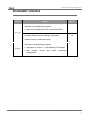
DOCUMENT UPDATES
Version
Changes
Page(s)
Changes in the application program:
• Improved management of the output order buffer
-
[2.1]_a
Example added about the “Multiply” parameter.
General revision of texts and styles
16
-
Changes in the application program:
[2.0]_a
http://www.zennio.com
• Integration of version 1.1 of the Building Thermostat.
• Slat precise
implemented.
control
and
direct
positioning
-
Technical Support: http://zennioenglish.zendesk.com
3
ACTinBOX CLASSIC HYBRID AD
1 INTRODUCTION
1.1 ACTINBOX CLASSIC - HYBRID
ACTinBOX Classic-Hybrid is a KNX actuator that combines in only one device the
following features:
4 multifunction binary outputs, up to 10A each, configurable as:
Up to 2 shutter channels (with or without slats/lamellas).
Up to 4 individual outputs.
Note: outputs 3 and 4 also admit the connection of capacitive loads.
6 specific inputs, configurable as:
Inputs 1-4: multifunction binary entries.
Input 5: multifunction binary input or temperature probe.
Input 6: multifunction binary input or movement detector.
Zennio Building Thermostat.
5x multi-operation logical function module.
Manual operation over the actuator outputs, by means of the Zennio infrared
remote control.
http://www.zennio.com
Technical Support: http://zennioenglish.zendesk.com
4
ACTinBOX CLASSIC HYBRID AD
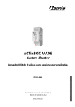
Figure 1 ACTinBOX Classic-Hybrid Actuator
1.2 INSTALLATION
ACTinBOX Classic-Hybrid connects to the KNX bus through the on-board KNX
connector.
Once the device is provided with power from the KNX bus, both the physical address
and the associated application program can be downloaded.
This actuator does not need any additional external power since it is entirely powered
through the KNX bus.
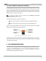
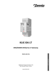
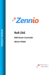
1 – Outputs
2 – Programming button
3 – Programming LED
4 – KNX connector
5 – Inputs
Figure 2 ACTinBOX Classic Hybrid. Element Scheme
The functionality of the main elements of the actuator is described below:
Programming button (2): a short press on this button sets the actuator into
the programming mode, making the associated LED (3) light in red.
Note: if this button is held while plugging the device into the KNX bus,
ACTinBOX Classic-Hybrid goes into secure mode. The LED will blink in red
every 0.5 s.
http://www.zennio.com
Technical Support: http://zennioenglish.zendesk.com
5
ACTinBOX CLASSIC HYBRID AD
Outputs (1): the screw terminal block (bundled with the original packaging)
must be plugged here to allow the connection of the different systems to be
controlled by the actuator. Wiring the terminal block may be carried out before
inserting it into the corresponding slot.
Inputs (5): the remaining screw terminal block (bundled with the original
packaging) must be plugged here, to allow the connection of the inputs to the
actuator. To ensure the adequate behaviour, the two terminals of the input
devices (push button, switch/sensor, temperature probe or movement
detector) must be connected, on the one hand, to the corresponding input
(connection points 1 to 6 in the terminal block) and on the other hand, to the
point identified as "C" on the terminal block.
To get detailed information about the technical features of ACTinBOX Classic-Hybrid,
as well as on security and on the installation procedure, please refer to the actuator
Datasheet, bundled with the original package of the device and also available at:
http://www.zennio.com .
2 CONFIGURATION
2.1 INDIVIDUAL OUTPUTS
ACTinBOX Classic-Hybrid incorporates 4 relay outputs that allow controlling different
loads autonomously. Each output can be enabled or disabled independently and
perform different functionalities.
Every individual output can be configured as normally open (the activation of the
output makes the relay close) or normally closed (the deactivation of the output
makes the relay open).
Besides the output type, ACTinBOX Classic-Hybrid allows the configuration of the
following functionalities for the individual outputs:
Timers. Permits a timed control over the outputs, being possible to set times
for the switch-on and for the switch-off of the output.
http://www.zennio.com
Technical Support: http://zennioenglish.zendesk.com
6
ACTinBOX CLASSIC HYBRID AD
Scenes. Allows running and/or saving a specific action over the output/s
where this function is enabled. The status of the outputs will vary depending
on the action set for the parameterized scene.
Alarm. Allows changing the status of the output where this function is
enabled, being possible to configure the status the output will be set to, both
on the alarm activation and on the alarm deactivation.
Note: the alarm behaves with priority over the other functionalities.
Start-up configuration: default or custom.
All these configuration options are explained in detail in section 3, ETS
Parametrization.
2.2 SHUTTER CHANNELS
The output channels of ACTinBOX Classic-Hybrid allow controlling up to 2 different
shutter drives (or similar window/door automated systems).
Thus, it is possible to control the movement of the shutter within the domotic
installation.
Basic control: moving the shutter up/down
Precise control: precise control of the shutter and the slats (for blinds
featuring slats).
Each channel (A and B) consists of two consecutive individual outputs; i.e., Channel A
is made of the individual outputs 1 and 2, while channel B consists of outputs 3 and 4.
The first output of every channel sends orders to raise the shutter, whereas the second
output sends orders to lower the shutter. Therefore, the cables of the shutter motor
carrying out these actions should be properly connected to the corresponding output of
the channel to perform the required action.
Table 1 shows the action carried out by the outputs of each channel:
http://www.zennio.com
Technical Support: http://zennioenglish.zendesk.com
7
ACTinBOX CLASSIC HYBRID AD
Channel
Outputs
Action
1
Move up
2
Move down
3
Move up
4
Move down
A
B
Table 1 Shutter channels: actions of the outputs
Each channel can be configured as a Shutter (No Slats) or as a Blind (with Slats).
Besides the shutter type, ACTinBOX Classic-Hybrid allows the configuration of the
following functionalities for the shutter channels:
Times. Sets the main times that define the movement of the shutter: the
length of the rising movement, the length of the descending movement, a
security time for making a pause in the movement of the motor when the
direction changes, and an additional movement time when the shutter gets to
its limit (top or bottom). For blinds with slats, it is also possible to configure a
“secondary time” for the slat movement length and for the slat step time.
Status objects. They report the current position of the shutter (and of the
slats, if applicable).
Precise control. Allows moving the shutter to a particular position (defined
by parameter). Moreover, for blinds with slats, it is also possible to establish a
particular position for the slats (value between 0% and 100%).
Scenes. Allows running and/or saving a specific action over the channel/s
where this function is enabled.
Alarms. Two alarms are available for each shutter channel. The
parameterized action will be executed when an alarm event is received.
Reverse movement. Allows inverse shutter control.
Direct positioning. Function that permits moving the shutter to a preset
specific position by sending a 1-bit communication object.
Start-up configuration. Default or custom.
All these options are explained in detail in section 3, ETS Parametrization.
http://www.zennio.com
Technical Support: http://zennioenglish.zendesk.com
8
ACTinBOX CLASSIC HYBRID AD
2.3 INPUTS
The actuator ACTinBOX Classic-Hybrid features 6 inputs, which may be configured as:
Binary input (all inputs: 1-6)
Temperature probe (only input 5)
Movement detector (only input 6)
Depending on the selected configuration, it may be necessary to connect different
external elements to the actuator inputs: push buttons or switches, temperature probes
(like model ZN1AC-NTC68 S/E/F from Zennio) or movement sensors (like model
ZN1IO-DETECT from Zennio).
Inputs configured as binary inputs may be push buttons or switches/sensors
(depending on the connected element). For every type, different customizable options
are available, as explained in section 3 of this manual.
Input 5 may be configured as a binary input or as a temperature probe. For this
configuration, it will be possible to set different parameters regarding the measurement
and sending of the temperature.
Input 6 may be configured as a binary input or as a movement detector. For this
configuration, up to 2 different detection channels can be enabled and configured to
react on movement detections or on the absence of movement, by setting custom
timings. As a result of the movement detection or non-detection, the channel will
transmit the corresponding information through the KNX bus, provided that the channel
is enabled (not locked). The movement detector also features a luminosity sensor that
allows configuring the sending of the movement detection or non-detection restricted to
a luminosity level, according to the parameterization.
2.4 THERMOSTAT
It is possible to enable and configure one thermostat with the Building functionality. The
operation and ETS configuration of the Zennio thermostat are described in the specific
documentation "Zennio Building Thermostat", available at: http://www.zennio.com.
http://www.zennio.com
Technical Support: http://zennioenglish.zendesk.com
9
ACTinBOX CLASSIC HYBRID AD
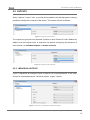
2.5 RELAY CONTROL USING THE IR REMOTE
The ACTinBOX Classic-Hybrid actuator incorporates a built-in infrared receiver, located
next to the programming LED. This functionality allows testing the actuator outputs by
making use of the Zennio infrared remote control (the one used to control the InZennio
Z38i and ZAS touch panels. See Figure 3).
Note: to control the outputs from the IR remote, it is necessary to have the
programming LED on (lighting in red).
The control of the outputs is carried out as follows:
Press over the right button: closes the relay of the corresponding output.
Press over the left button: opens the relay of the corresponding output.
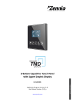
Figure 3 shows a representation of the buttons of the IR remote that must be pressed
depending on the output to be remotely controlled.
Figure 3 Controlling the outputs from the IR remote
The IR control of the device outputs is only provided for testing purposes. None of the
parameterized functions (such as scenes, timers, etc.) is taken into account for opening
/ closing the relays remotely.
3 ETS PARAMETRIZATION
To begin with the parameterization of the ACTinBOX Classic-Hybrid actuator it is
necessary, once the ETS application is running, to import the database of the product
(ACTinBOX Hybrid AD application program).
http://www.zennio.com
Technical Support: http://zennioenglish.zendesk.com
10
ACTinBOX CLASSIC HYBRID AD
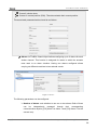
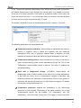
Next, the device must be added to the project where desired. Finally, right-click on the
device and select "Edit parameters" to start with the configuration.
The following sections provide a detailed explanation about each of the different
functionalities of the application in ETS.
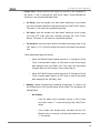
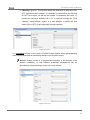
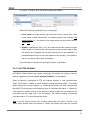
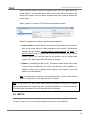
3.1 DEFAULT CONFIGURATION
This section shows the default configuration the device parameterization starts from.
When the parameter edition is entered for the first time, the following window will come
up:
Figure 4 Configuration screen by default
As shown in Figure 4, outputs, inputs and logical functions are disabled by default, so
there will be no communication objects available until the user enables some of the
functions of the actuator.
If the parameter "Sending of indication objects on bus voltage recovery" is set to
“Yest”, two new 1-bit communication objects will show up ("Reset 0" and "Reset 1"),
which will send to the KNX bus the values "0" and "1" after a bus power failure, in order
to recover the communication with the rest of the devices in the installation. This
sending may be immediate or after a configured delay (in seconds).
The left-side menu also shows the access to the Thermostat configuration, disabled by
default (see Section 3.5).
http://www.zennio.com
Technical Support: http://zennioenglish.zendesk.com
11
ACTinBOX CLASSIC HYBRID AD
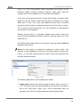
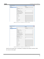
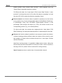
3.2 OUTPUTS
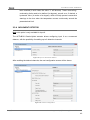
When “Outputs” is set to “Yes”, a new tab will be added to the left-side panel, making it
possible to configure the outputs of the device. This screen will look as follows:
Figure 5 Configuring the outputs
The outputs are grouped into channels (Channel A and Channel B, both disabled by
default), with two outputs each. A drop-down list permits configuring the behaviour of
each channel, as individual outputs or shutter channels.
Figure 6 Configuring the channels
3.2.1 INDIVIDUAL OUTPUTS
Figure 7 represents an example of how a channel can be parameterized: in this case,
channel A is parameterized as “individual outputs” (output 1 and 2).
Figure 7 Channel A configured as individual outputs
http://www.zennio.com
Technical Support: http://zennioenglish.zendesk.com
12
ACTinBOX CLASSIC HYBRID AD
Once the output is enabled, the ETS topology will automatically display the following
communication objects (1-bit each):
[OX]
ON/OFF:
allows
activating
(ON)
or
deactivating
(OFF)
the
corresponding output by sending the value "1" or "0", depending on the
parameterized output type.
[OX] Status: shows the current status of the output (active or inactive).
[OX] Block: allows locking/unlocking the output (i.e., disabling/enabling its
control) by sending the values "1" or "0" to the object, respectively.
Note: only the Alarm function has a higher priority than the block function; if
an alarm signal arrives when the output is locked, the output will be set to the
status defined by the alarm function. When the alarm gets deactivated, the
output returns to the lock status.
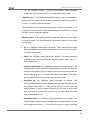
The first thing to be parameterized is the type of each output of the channel:
Normally open: the output will be considered as active (ON) when the relay
stays closed and inactive (OFF) when the relay stays open.
Normally closed: the output will be considered as active (ON) when the relay
stays open and inactive (OFF) when the relay stays closed.
Next, the list of functions available for each output:
Timers: allow performing a timed control of the outputs, both through a
simple timer and/or through an intermittent sequence (flashing).
Figure 8 Timers screen. Simple timer
http://www.zennio.com
Technical Support: http://zennioenglish.zendesk.com
13
ACTinBOX CLASSIC HYBRID AD
Simple timer: allows switching the output on and off on the reception of
the values “1” and “0” through the “[OX] Timer” object. These switches are
subject to a set of parameterizable times:
•
On Delay: time the actuator will wait before switching on the output
once the ON order has been received (through the “[OX] Timer” object).
The value “0” will cause an immediate response.
•
Off delay: time the actuator will wait before switching off the output
once the OFF order has been received (through the “[OX] Timer”
object). The value “0” will cause an immediate response.
•
On Duration: time the output remains ON before switching back to the
OFF status. A “0” in this field means the output will remain permanently
ON.
These parameters apply as follows:
o
When ACTinBOX Classic-Hybrid receives a "1" through the "[OX]
Timer" communication object, an ON order is sent to the output
after waiting for the “On Delay” time. The output will stay switch
off again after the “On Duration” time (if other than 0).
o
When ACTinBOX Classic-Hybrid receives a "0" through the "[OX]
Timer" communication object, an OFF order is sent to the output
after waiting for the “Off Delay” time.
•
Multiply: allows progressively increasing (multiplying), in runtime, the
On Duration time or the On/Off delays of the output. Two situations are
distinguished:
o
No multiply:
-
If the On delay count is already running, it will be reset
every time a new “1” is received through the “[OX] Timer”
object.
-
If the output has already been activated and the On
Duration time is counting, it will be reset whenever a new
“1” is received.
http://www.zennio.com
Technical Support: http://zennioenglish.zendesk.com
14
ACTinBOX CLASSIC HYBRID AD
-
If the Off delay count is already running, it will be reset
every time a new “0” is received.
o
Multiply:
-
If the On delay count is already running and the value “1”
is received several times through the “[OX] Timer” object,
then the actual delay time will be “n” times the
parameterized time, being “n” the number of times the
value “1” is received .
-
If the output has already been activated and while the On
Duration time is counting the value “1” is received several
times, then the actual duration will be “n” times the
parameterized time, being “n” the number of times the
value “1” is received.
-
If the Off delay count is already running and the value “0”
is received several times, then the actual delay time will
be “n” times the parameterized time, being “n” the
number of times the value “0” is received.
Note: the Multiply option may result particularly useful under
parameterizations with no ON and OFF delays. Nevertheless, as
already explained and as the following example shows, these
delay times, if parameterized with a value other than 0, do also
admit multiplication.
http://www.zennio.com
Technical Support: http://zennioenglish.zendesk.com
15
ACTinBOX CLASSIC HYBRID AD
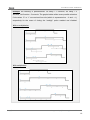
Example: the following is parameterized: On Delay = 3 seconds; Off Delay = 3
seconds, On Duration = 5 seconds. The graphs bellow reflect some possible situations
if the values “0” or “1” are received from the (which is represented as →0 and →1),
respectively for the cases of having the “multiply” option enabled and disabled.
With no multiplication:
With multiplication:
http://www.zennio.com
Technical Support: http://zennioenglish.zendesk.com
16
ACTinBOX CLASSIC HYBRID AD
Flashing (Figure 9). This function allows the execution of alternating ONOFF sequences when needed. It is possible to parameterize the ON and
an OFF time length, as well as the number of repetitions (the value “0”
makes the sequence endless until a “0” is received through the “[OX]
Flashing” communication object). It is also possible to define the final
status (ON or OFF) of the output after the last repetition.
Figure 9 Flashing
It is important to keep in mind that ACTinBOX Classic-Hybrid allows parameterizing
both a simple timer and an intermitting sequence for the same output.
Scenes: scenes consist of a synchronized activation of the devices in the
domotic installation, so that different predefined atmospheres can be
generated by simply sending a scene value over the bus.
Figure 10 Scenes
http://www.zennio.com
Technical Support: http://zennioenglish.zendesk.com
17
ACTinBOX CLASSIC HYBRID AD
There is a 1-bye communication object associated with Scenes for the
individual outputs: "Scenes (Individual Outputs)", which shows when the
"Outputs" tab in ETS is enabled, even if the outputs are disabled.
In the case of the individual outputs, scenes allow linking a numerical value
(between 1 and 64, where 0 means that the option is disabled) to an output
status (OFF or ON). Thus, when the predefined scene value is received
through the Scenes object, the parameterized action for the output (a switchoff or a switch-on) will be performed; so it will be possible to create different
environments in the installation.
Besides running scenes, it is possible to learn (save) scenes, taking into
account that the associated numerical values for learning scenes are in the
range 128-191.
ACTinBOX Classic-Hybrid allows running and/or learning up to 5 different
scenes for each output.
Alarm: for each output it is possible to configure an alarm, which, once
activated, will have priority over the rest of the orders that the actuator may
receive, i.e., any order received while the alarm is active will be ignored until
the alarm becomes inactive.
Figure 11 Alarm
The following parameters can be configured for alarms:
Trigger value: sets the value that will trigger the alarm status. It can be "1"
or "0". The alarm status will be activated when the value set in this field is
sent to the “[OX] Alarm” object, and it will be deactivated when the
opposite value is sent to the aforementioned communication object.
http://www.zennio.com
Technical Support: http://zennioenglish.zendesk.com
18
ACTinBOX CLASSIC HYBRID AD
Cyclical monitoring period (minutes): defines, for the case of having a
periodically-sent alarm object (“1” or “0”, as corresponding each time), the
maximum permitted time without receiving the “no alarm” value (“[OX]
Alarm” = value contrary to the parameterized trigger value) before the
actuator automatically assumes the alarm status, foreseeing the possibility
of a failure in the transmitting device. If for whatever reason the monitoring
period expires, ACTinBOX Classic-Hybrid will trigger the parameterized
action (unless it does not imply a change in the output status). This will not
happen while the “no alarm” value keeps being sent before each
monitoring period expires. The cyclical monitoring can be disabled by
simply setting a 0 under this filed.
The following example is provided for a better comprehension:
Example:
Suppose that a cyclical monitoring period of 2 minutes is configured. The trigger value
is “1” and the reaction of the actuator when the alarm is activated consists in switching
on the output, while when the alarm is deactivated, the output will be switched off.
Assuming that the output is off, the alarm becomes active (“[OX] Alarm=1”), so the
output is switched on. While the alarm is not deactivated, any action over the output will
be ignored. After some time (t2), the alarm is deactivated (“[OX] Alarm=0”), which
makes the output switch from ON to OFF. Before the parameterized cyclical monitoring
period (2 minutes) ends, a new alarm deactivation order arrives, so the time count
starts again. After 2 minutes without receiving further values through the alarm object,
the alarm will be automatically activated, making the output status switch on. As before,
any action over the output will be ignored until the alarm is deactivated. See the
following figure.
“[OX] Alarm”=1
Automatic Alarm
Activation
“[OX] Alarm”=0
“[OX] Alarm”=0
Output status
t1
http://www.zennio.com
t2
2 minutes
2 minutes
Technical Support: http://zennioenglish.zendesk.com
19
ACTinBOX CLASSIC HYBRID AD
Response: sets the response (status) of the actuator output when the
alarm is activated:
•
No change.
•
ON.
•
OFF.
•
Flashing: 3 drop-down lists are shown to configure the ON Duration, the
OFF Duration and the number of repetitions of the sequence.
Deactivation: two different procedures are provided to deactivate an
active alarm:
•
Normal: depending on what was parameterized under “Trigger Value”,
the alarm will be deactivated as soon as the actuator receives a “0” or a
“1” through the alarm object.
•
Frozen: this method requires a normal deactivation, plus the reception
of the value “1” over the “[OX] Unfreeze Alarm” object (if the latter does
not occur, the alarm status will still be active). This method makes the
channel output remain locked (even when the alarm situation is over)
until it is externally (or manually) enabled.
End (reaction when alarm ends): this parameter sets the status that will
be adopted by the output once the alarm finishes:
•
No change
•
ON
•
OFF
•
Last (the output returns to the status it had before the alarm)
Start-up configuration: defines the state (ON/OFF) that will be adopted by
the outputs when the device recovers from a bus power failure, or after an
ETS download. A default or a custom configuration may be selected.
Selecting the default configuration will make the output stay off after a partial
or complete ETS download, while after a bus power failure, the status of the
output will be the same it had before the failure (ON or OFF).
http://www.zennio.com
Technical Support: http://zennioenglish.zendesk.com
20
ACTinBOX CLASSIC HYBRID AD
If “custom” is chosen, ETS will show the following window:
Figure 12 Start-up configuration: custom.
Where the following parameters can be configured:
Initial status: this field defines the initial status of the output after a bus
power failure or after a download. The following options are available: last
saved position (i.e., the status of the output before the bus power failure),
ON or OFF.
Update: enabling this field (“Yes”) will make the actuator send the output
status to the bus (through the corresponding communication object) after
the start-up as a feedback for the rest of the devices in the installation. A
parameterizable delay can also be applied to this sending. If the delay is
set to 0, the status will be sent immediately.
The initial status is always sent through the object “[OX] Status”.
3.2.2 SHUTTER CHANNEL
ACTinBOX Classic-Hybrid also allows configuring its outputs as shutter channels,
making it possible to control up to 2 separate shutters in an installation.
When a channel is configured in ETS as a shutter channel, a 1-bit communication
object (“[CX] Block”) related to each enabled channel becomes visible. This object
allows locking the channel outputs (i.e., disabling the control over them through both
the ON/OFF and the timed control objects) when it is received with value “1”. Moreover,
if the shutter is already moving at the moment of being locked, the movement will be
interrupted and any order over it will be ignored. The channel outputs will become
unlocked when a “0” is sent through this object.
Note: only the “alarm” function has a higher priority than the “block” function. If an
alarm signal arrives while the channel is locked, the shutter will adopt the position
http://www.zennio.com
Technical Support: http://zennioenglish.zendesk.com
21
ACTinBOX CLASSIC HYBRID AD
configured for the alarm. Once the alarm is deactivated, the shutter will recover the
position defined for the locked status.
The first parameter to be configured is the type of the shutter:
Shutter (no slats): typical shutter with a simple movement up/down. If this
type is selected, two communication objects are enabled: “[CX] Move” and
“[CX] Stop” to move the shutter up/down and to stop it, respectively.
In addition, the following remark is shown for this type: "Slats positions will be
ignored for Shutter types", which means that function parameters related to
slat positions (%) will not be taken into account.
Blind (with slats): special slat shutters where both the shutter itself and the
slats/lamellas are controlled with a single drive. ACTinBOX Classic-Hybrid
allows controlling both movements: the slat rotation (which permits varying
the level of the incident light) and the movement (up/down) of the blind. Two
communication objects are enabled for this purpose: "[CX] Move" (which will
send the orders to move the blind up/down) and "[CX] Stop/Step". If the
device receives a “0” or a “1” through the latter when the blind is already in
motion, the movement will be interrupted, while if the blind was not in motion,
receiving a “0” through this communication object will make the slats rotate
upwards, while receiving a “1” will make them rotate downwards. These step
movements are useful to correct both the slat and the blind position together.
To get detailed information about blinds with slats and their ETS
configuration, please refer to ANNEX I. Slats precise control.
The next figures show the screens that contain the parameterizable options for
channels configured as shutters (no slats) or as blinds (with slats).
http://www.zennio.com
Technical Support: http://zennioenglish.zendesk.com
22
ACTinBOX CLASSIC HYBRID AD
Figure 13 Channel A configured as a shutter (no slats)
Figure 14 Channel B configured as a blind (with slats)
Apart from the shutter type, it is necessary to configure some specific functions, which
are common to both types:
http://www.zennio.com
Technical Support: http://zennioenglish.zendesk.com
23
ACTinBOX CLASSIC HYBRID AD
Times: this section allows setting the times (in tenths of seconds) that define
to the shutter movement.
Main time (Shutter length): this is the time the shutter needs to move all
the way down or up. In case the shutter does not take similar times for
both directions, parameter “Are total time up and down different?” should
be set to “Yes”. In such case, this Main time will define the time required to
move the shutter all the way down, while a secondary parameter (“Total
Time Up”) will become available to define the time required for the inverse
movement.
It is not necessary to periodically calibrate this parameter, since the exact
shutter position is stored by ACTinBOX Classic-Hybrid at any time, even
after power failures.
Security time (pause to change the movement direction): this is the
time reserved by the actuator, as a preventive measure to protect the
shutter drive, when the movement switches from one direction to the
inverse. If the device receives an order to lower the shutter while it is being
raised, ACTinBOX Classic-Hybrid will temporarily interrupt the movement
(security time) and will afterwards lower the shutter. It is advisable to set a
value not lower than 5 tenths of a second (the default value).
Are total time Up and Down different? Heavy shutters may require
different times to move up and to move down. When this happens, this
field should be set to “Yes”, making the already mentioned “Main time
(Shutter length)” parameter be interpreted as the time required to lower the
shutter, while a secondary parameter will be provided to define the time
required to raise it.
Additional time when the shutter gets the limit: this parameter is useful
to prevent small maladjustments and to ensure that the shutter always
gets to the lowest or highest position. This is done by defining an extra
time to keep the drive moving once the rising/lowering times end. This
parameter is not visible by default; however it is advisable to give it a value
to guarantee a proper behaviour in the shutter.
http://www.zennio.com
Technical Support: http://zennioenglish.zendesk.com
24
ACTinBOX CLASSIC HYBRID AD
If the shutter is configured as a blind with slats (Figure 14), some more specific
parameters appear. All of them are explained in detail in ANNEX I. Slats precise
control.
Note: after programming the device from ETS from ETS and unless a custom start-up
configuration has been parameterized, ACTinBOX Classic-Hybrid will assume the
shutter as completely raised, so any raising order will be ignored.
The following is an example of a possible shutter configuration.
Example:
Channel A (shutter without slats) takes 15 seconds to be lowered and 20 to be raised.
Additional times for direction changes (5 tenths of a second) and at the end of the
movement (2 seconds) are also required. The required parameterization is as follows:
The following parameters add functionality or special features to both shutter types
(with or without slats):
Status object: this function provides a 1-byte communication object ("[CX]
Current Shutter Position") which will show, at any time, the exact position of
the shutter in percentage (%). This object throws the value 0 (or 0%) when
the shutter in completely up and 255 (or 100%) when it is completely down.
The remaining values represent intermediate positions.
It is possible to set, by parameter, whether the shutter position will be sent
every second or not. This is done by enabling or disabling “Send current
http://www.zennio.com
Technical Support: http://zennioenglish.zendesk.com
25
ACTinBOX CLASSIC HYBRID AD
shutter position every second while moving?”, which appears once the
“Status Object” parameter has been enabled.
For Blinds with slats, the 1-byte object "[CX] Current Slats Position" is also
provided. It will show the value 0 (0%) when the slats are completely "up" and
the value 255 (100%) when the slats are completely "down".
Precise control: this function makes it possible to actually move the shutter
to any position via a 1-byte communication object ("[CX] Shutter Positioning",
in percentage). Every time ACTinBOX Classic-Hybrid receives a new
percentage value through this object (e.g. 50%), the shutter moves to the
corresponding position (e.g., the central position).
For blinds with slats, the actuator also implements the 1-byte object "[CX]
Slats Positioning" for setting the desired position (in percentage) for the slats.
Scenes: this function makes it possible to use scenes to control the shutters.
It allows choosing precise positions where the shutter will be moved to upon
the reception of certain scene numbers through the 1 byte object “Scenes
(Shutter Channels)”.
Apart from running scenes, it is possible to learn (save) scenes, taking into
account that the values that should be received to learn a scene must be in
the range 128-191 (values 0-63 are reserved for running scenes).
Up to 5 scenes can be run and/or leant, for each shutter channel.
http://www.zennio.com
Technical Support: http://zennioenglish.zendesk.com
26
ACTinBOX CLASSIC HYBRID AD
Figure 16 Scenes
The “Scene” parameter indicates the scene value the shutter will react to. If
this value is 0, the corresponding option is disabled.
“Response” sets the precise position where the shutter will be moved to when
the above scene number arrives from the bus. The shutter can be moved
completely up, completely down, or to a specific intermediate position (in
percentage, from 0% to 100%). In case of choosing the latter, parameter
"Shutter specific position?" will become visible to allow the definition of a
specific shutter position (through the "Select Shutter Position [%]"parameter,
after selecting "Yes") or to make the shutter stay as is.
For blinds with slats it is also possible to configure a specific position for the
slats (via the parameter "Select Slats Position [%]") when the configured
scene number is received, or to make them maintain their current position.
The following example illustrates the configuration process.
Example:
Consider a facility where 3 scenes will be distinguished (values “4”, “6” and “18”) and
where ACTinBOX Classic-Hybrid will be used to move a blind with slats to precise
positions on the reception of these scene values:
Scene 4: shutter up
http://www.zennio.com
Technical Support: http://zennioenglish.zendesk.com
27
ACTinBOX CLASSIC HYBRID AD
Scene 6: shutter down
Scene 18: central position (50%). The slats maintain their current position.
The associated parameterization should be as follows.
Alarms: ACTinBOX Classic-Hybrid allows configuring up to 2 alarms for each
shutter channel. This function is designed for cases in which the actuator
must react to an alarm situation. Having two alarms configured allows
carrying out different reactions to two external events.
Figure 17 Alarms
The following parameters can be configured:
Number of alarms: sets whether to use one or two alarms. Both of them
can
be
independently
managed
through
their
corresponding
communication objects (“[CX] Alarm” for Alarm 1 and “[CX] Alarm 2” for the
second one).
http://www.zennio.com
Technical Support: http://zennioenglish.zendesk.com
28
ACTinBOX CLASSIC HYBRID AD
It is important to keep in mind that Alarm 1 has a higher priority than Alarm
2. This means that if a channel is under the Alarm 2 status and Alarm 1
occurs, then the shutter will switch to the Alarm 1 status and only switch
back to the Alarm 2 status once Alarm 1 finishes. Analogously, when the
channel is under the Alarm 1 status and Alarm 2 occurs, Alarm 1 prevails.
Trigger value: sets the value (“1” or “0”) that will trigger the alarm status.
This value is intended to be received through object “[CX] Alarm” (or “[CX]
Alarm2”).
Cyclical monitoring period (minutes): defines, for the case of having a
periodically-sent alarm object (“1” or “0”, as corresponding each time), the
maximum permitted time without receiving the “no alarm” value (“[OX]
Alarm” = value contrary to the parameterized trigger value) before the
actuator automatically assumes the alarm status, foreseeing the possibility
of a failure in the transmitting device. If for whatever reason the monitoring
period expires, ACTinBOX Classic-Hybrid will trigger the parameterized
action (unless it does not imply a change in the output status). This will not
happen while the “no alarm” value keeps being sent before each
monitoring period expires. The cyclical monitoring can be disabled by
simply setting a 0 under this filed.
The following example illustrates the above behaviour:
Example:
Suppose that a cyclical monitoring period of 3 minutes is configured. The trigger value
is “1” and the reaction of the actuator when the alarm is activated consists in moving
the shutter all the way up, while when the alarm is deactivated, the shutter will be
raised. Assuming that the shutter has been lowered, when the alarm becomes active
the actuator will begin raising the shutter. While the alarm is not deactivated, any action
over the shutter channel will be ignored by the actuator. After some time (t2), one “0”
arrives through the alarm object, which makes the alarm turn off and the shutter be
raised. Before the parameterized cyclical monitoring period (3 minutes) ends, a new
alarm deactivation order arrives, so the time count starts again. After 3 minutes without
receiving further values through the alarm object, the alarm will be automatically
http://www.zennio.com
Technical Support: http://zennioenglish.zendesk.com
29
ACTinBOX CLASSIC HYBRID AD
activated, making the shutter move up again. As before, any action over the shutter will
be ignored until the alarm is deactivated. See the following figure
“[CX] Alarm”=1
“[CX] Alarm”=0
Automatic Alarm
Activation
“[CX] Alarm”=0
Output status
t1
t2
3 minutes
3 minutes
Response: sets the response order to be sent to the shutter when the
alarm is activated:
•
Stop.
•
Up.
•
Down.
•
Specific position.
When the latter is chosen, a new drop-down list is shown, letting the
integrator set a value for this specific position, in the range 0% (completely
up) to 100% (completely down).
For blinds with slats, an option called "Select Slats position [%]" will also
become visible, making it possible to set a position for the slats between
0% (totally open or "up") and 100% (totally closed or "down").
Deactivation: two different procedures are provided to deactivate an
active alarm:
•
Normal: depending on what was parameterized under “Trigger Value”,
the alarm will be deactivated as soon as the actuator receives a “0” or a
“1” through the corresponding alarm object.
http://www.zennio.com
Technical Support: http://zennioenglish.zendesk.com
30
ACTinBOX CLASSIC HYBRID AD
•
Frozen: this method requires a normal deactivation, plus the reception
of the value “1” over the corresponding unfreeze alarm object (if the
latter does not occur, the alarm status will still be active). This method
makes the channel output remain locked (even when the alarm situation
is over) until it is externally (or manually) enabled.
End: this parameter sets the desired shutter position once the alarm
becomes inactive:
•
Current position.
•
Up.
•
Down.
•
Last position (before the alarm).
Reverse movement: this function makes it possible to control a shutter with
the usual orders inverted (ACTinBOX Classic-Hybrid normally raises the
shutter when the value "0" is received through the object "[CX] Move" and
stops it with value "1"). Therefore, if this function is enabled, ACTinBOX
Classic-Hybrid will also raise the shutter when the value "1" is received
through object "[CX] Reversed Movement", and will lower it on the reception
of the value “0”.
This reverse control is compatible with the usual control, since “[CX] Move”
and “[CX] Reversed Movement” are provided as separate objects for normal
and reverse control, respectively.
Reverse control becomes particularly useful when a centralised OFF order is
sent over the installation to turn the lights off and to lower the shutters at the
same time. In this case, the value “0” can be sent to the light ON/OFF objects
and to the shutter “Reverse movement” objects.
Direct positioning: this function allows moving the shutter to a preset
position by a simple 1-bit order (through “[CX] Direct Positioning” and “[CX]
Direct Positioning 2”). When a “1” is received through one of these objects,
the shutter will be moved to the parameterized position. When a “0” is
received, no action is performed.
http://www.zennio.com
Technical Support: http://zennioenglish.zendesk.com
31
ACTinBOX CLASSIC HYBRID AD
Figure 18 Direct positioning
It is possible to configure the following parameters:
Total direct positionings: one or two direct positioning functions can be
enabled.
Select shutter position [%]: sets the exact position to move the shutter to
(0%=Top; 100%=Bottom).
For blinds with slats, an option called "Select Slats position [%]" will also
become visible, making it possible to set a position for the slats when the
value "1" is received through the corresponding positioning object.
If two direct positioning controls are configured, two boxes will be available
here: “Select Shutter Position 1” and “Select Shutter Position 2” (as well as
"Select Slats position 1" and "Select Slats position 2" for blinds with slats).
New positions saving: allows (“Yes”) or not (“No”) saving new direct
positions. After enabling this option, one or two new communication
objects appear (depending on the number of direct positioning controls):
“[CX] Save Position” and “[CX] Save Position 2”. To overwrite the
parameterized direct position it is necessary to send a “1” to these objects
when the shutter is at the desired position.
Note: saving a new position is not possible while the shutter is moving.
Start-up configuration: defines the shutter state that the device will
assume/order when it recovers from a bus power failure, or after an ETS
download. A default or a custom configuration may be selected.
If “default” is chosen, after a partial or complete download from ETS,
ACTinBOX Classic-Hybrid will assume the shutter is completely up (0%),
independently of its actual status. For blinds with slats, ACTinBOX Classichttp://www.zennio.com
Technical Support: http://zennioenglish.zendesk.com
32
ACTinBOX CLASSIC HYBRID AD
Hybrid assumes that the slats are completely open (0%), no matter what their
actual status is. On the other hand, after a bus power failure, the device will
assume the shutter (and the slats) maintains the same state as before the
power failure.
When “custom” is chosen, ETS will show the following window:
Figure 19 Custom Start-up configuration
Where it is possible to configure the following parameters:
Initial position: this field defines the desired initial position for the shutter
after a bus power failure or after programming the device. The following
statuses can be chosen: Current position (keeps stopped), up, down, or
specific position (which moves the shutter to the position set for "Select
shutter position [%]" and the slats to the position set for “Select slats
position [%]”, both shown after this option is chosen).
Update: by enabling this field (“Yes”), the position status object will be sent
to the bus as a feedback for the rest of the devices in the installation. In
addition a delay can be applied to this sending. If the value 0 is set, the
status is sent immediately.
Note: the initial status is always sent through the object “[CX] Current Shutter
position” (and "[CX] Current Slats position", for slats).
Note: in the event of a bus power failure while the shutter is moving, ACTinBOX
Classic-Hybrid opens the output relay prior to being unpowered, as a security measure.
The interrupted movement is not resumed after the bus recovery.
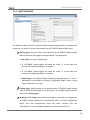
3.3 INPUTS
If “Inputs” is set to “Yes”, a new tab will appear in the menu on the left side.
http://www.zennio.com
Technical Support: http://zennioenglish.zendesk.com
33
ACTinBOX CLASSIC HYBRID AD
Figure 20 Inputs configuration
Inputs can be configured as: push button, switch/sensor, temperature probe (only
input 5) and movement detector (only input 6).
All these options are explained in detail in the following sections.
3.3.1 PUSH BUTTON
Figure 21 Binary input: Push button
From the default window (Figure 20) it will be possible to customize the behaviour of
the push button connected to the actuator input, through the following options:
Short press: it allows selecting an action to be carried out after a short press
on the pushbutton connected to the input channel. The options are:
No action. Nothing (no action is performed).
Sending of 0/1. A new window is shown, from which (through the
"Response" field) it is possible to select a value that will be sent to the
KNX bus after a short press:
•
"0": the "[Ix][Short press] 0" binary communication object becomes
visible, and will send the value "0" to the bus after a short press.
http://www.zennio.com
Technical Support: http://zennioenglish.zendesk.com
34
ACTinBOX CLASSIC HYBRID AD
•
"1": the "[Ix][Short press] 1" binary communication object becomes
visible, and will send the value "0" to the bus after a short press.
"Switching 0/1": the "[Ix][Short press] Switching" binary communication
object becomes visible, and will perform an alternate sending of the values
"0" and "1" to the bus on short presses.
The transmission of the selected value can be carried out cyclically, i.e., it
is possible to parameterize a periodical sending to the KNX bus, through
the field "Cyclical response sending".
Shutter control. This function allows sending the KNX bus a 1-bit object
to control shutters. The field "Response" defines the order to be sent after
a short press:
•
Up: the "[Ix][Short press] Move up shutter" 1-bit communication object
becomes enabled and will send the KNX bus the move up order (value
"0") after a short press.
•
Down: the "[Ix][Short press] Move down shutter" 1-bit object becomes
enabled and will send the KNX bus the move down order (value "1")
after a short press..
•
Up/Down (switched): the "[Ix][Short press] Move up/down shutter" 1-bit
communication object becomes enabled and will perform an alternate
sending to the KNX bus of the orders to move up and to move down the
shutter (values "0" and "1", respectively) after short presses. This option
allows handling the shutter through just one input button.
•
Stop/Step Up: the "[Ix][Short press] Stop/Step up shutter" 1-bit
communication object becomes enabled and will send the KNX bus the
stop shutter order (value “0”). If the shutter was not in motion, this stop
order performs a short movement upwards (in the case of blinds with
slats, this permits moving them one step up). In both cases, the value
sent to the KNX bus is "0".
•
Stop/Step Down: the "[Ix][Short press] Stop/Step down shutter" 1-bit
communication object becomes enabled and will send the KNX bus the
stop shutter order (value “1”). If the shutter was not in motion, this stop
http://www.zennio.com
Technical Support: http://zennioenglish.zendesk.com
35
ACTinBOX CLASSIC HYBRID AD
order performs a short movement downwards (in the case of blinds with
slats, this permits moving them one step down). In both cases, the
value sent to the KNX bus is "1".
•
Stop/Switched
Step:
the "[Ix][Short
Press]
Stop/Step
Shutter
(switched)" 1-bit communication object becomes enabled and will send
the KNX bus the stop shutter order (with values “1” and “0”, alternating
after every short press). If the shutter was not in motion, this stop order
performs a short movement upwards or downwards (in the case of
blinds with slats, this permits moving them one step up or down).
Dimmer control. This function allows sending the KNX bus orders to
control a dimmer (light regulator). The field "Response" is provided for the
selection of the order to be sent after a short press:
•
Light ON: the "[Ix][Short press] Dimmer ON" 1-bit communication
object becomes enabled and will send the KNX bus a switch-on order
(value "1") after a short press.
•
Light OFF: the "[Ix][Short press] Dimmer OFF" 1-bit ommunication
object becomes enabled and will send the KNX bus a switch-off order
(value "0") after a short press.
•
Light ON/OFF (switched): the "[Ix][Short press] Dimmer ON/OFF" 1-bit
communication object becomes enabled and will send the KNX bus an
alternate switch order (values "1" and "0", respectively for switch-on and
switch-off orders) after short presses.
•
Brighter: the "[Ix][Short press] Brighter" 4-bit communication object
becomes enabled and will send the dimmer, after a short press, an
order to increase the light level according to the parameterized dimming
step (see Table 2). A second short press will send an order to interrupt
the dimming process (value “0”).
•
Darker: the "[Ix][Short press] Darker" 4-bit communication object
becomes enabled and will send the dimmer, after a short press, an
order to decrease the light level according to the parameterized
dimming step (see Table 2). A second short press will send an order to
interrupt the dimming process (value “8”).
http://www.zennio.com
Technical Support: http://zennioenglish.zendesk.com
36
ACTinBOX CLASSIC HYBRID AD
•
Brighter/Darker (switched): the "[Ix][Short press] Brighter/darker" 4-bit
communication object becomes enabled and will send the dimmer, after
a short press, an order to increase the light level according to the
parameterized dimming step (see Table 2). A second short press will
send an order to interrupt the dimming process (“0”). A third press
causes sending an order to decrease the light level, while another one
will interrupt such order (“8”). Further presses will make the described
sequence start again.
Note: the last three options require defining the dimming step to be applied,
i.e., how much the brightness level will be increased or decreased by the
Dimmer after every press. Please refer to Table 2 for the configurable
steps.
Note: dimmers typically perform step dimming progressively, being it
possible to interrupt the process as soon as a stop order arrives. Therefore,
it is advisable to parameterize a step of 100%, so a sole initial press and a
later stop press are enough to set the amount of light at the desired level.
Dimming step
Necessary presses for a
complete regulation (0-100%)
(1) 100%
1
(2) 50%
2
(3) 25%
4
(4) 12.5%
8
(5) 6.25%
16
(6) 3.1%
32
(7) 1.5%
64
Table 2 Dimming step
Sending of a Scene. This function allows sending the KNX bus a 1-byte
scene control order. The "Response" field is provided to select the action
to be carried out on short presses:
•
Run Scene: the "[Ix][Short press] Run scene" 1-byte object is enabled
and will send the bus, after a short press, a value (between 1 and 64,
parameterizable) for the execution of a scene.
http://www.zennio.com
Technical Support: http://zennioenglish.zendesk.com
37
ACTinBOX CLASSIC HYBRID AD
•
Save Scene: the "[Ix][Short press] Save scene" 1-byte object is enabled
and will send (after a short press) the bus a scene save order, so it can
be executed afterwards.
Long press: it allows selecting the option that will be carried out when a long
press is performed on the pushbutton connected to ACTinBOX ClassicHybrid. The available options are the same as for Short press, however the
orders to increase/decrease the light level will not require a second press to
be interrupted – they will be as soon as the first long press ends.
Threshold time: defines the minimum time (in tenths of a second) that the
pushbutton must be held in order to consider the action as a long press.
Response delay (short press): sets a delay (in tenths of a second) for the
sending of the object associated to the reaction to the short press. Therefore,
after a short press, ACTinBOX Classic-Hybrid will wait for this parameterized
time before sending the bus the value of the corresponding object. For an
immediate sending (no delay), just leave the value 0 for this field.
Response delay (long press): sets a delay (in tenths of a second) for the
sending of the object associated to the reaction to the long press. Therefore,
after a long press, ACTinBOX Classic-Hybrid will wait for this parameterized
time before sending the bus the value of the corresponding object. For an
immediate sending (no delay), just leave the value 0 for this field.
Block: the "[Ix] Block" binary object is enabled, making it possible to block
any action performed over the ACTinBOX Classic-Hybrid input (i.e., disabling
the input control) by simply sending the value "1" through the block object,
after which ACTinBOX Classic-Hybrid will ignore any press or signal received
from the input device. Once the value "0" arrives, the input will be enabled
again.
Actions or presses performed while the input is locked will not be taken into
account when the input becomes unlocked again.
http://www.zennio.com
Technical Support: http://zennioenglish.zendesk.com
38
ACTinBOX CLASSIC HYBRID AD
3.3.2 SWITCH/SENSOR
Figure 22 Binary entry: Switch/Sensor
The default window (Figure 21) provides with the required parameters to customize the
behaviour of a switch or sensor connected to the ACTinBOX Classic-Hybrid input:
Rising edge: sets the action to be performed by ACTinBOX Classic-Hybrid
when it detects a rising edge in the input signal. The options are:
No action: no action is performed.
0: ACTinBOX Classic-Hybrid will send the value "0" to the KNX bus
through the "[Ix][Sensor] Edge" 1-bit object.
1: ACTinBOX Classic-Hybrid will send the value "1" to the KNX bus
through the "[Ix][Sensor] Edge" 1-bit object.
Switching 0/1: ACTinBOX Classic-Hybrid will send the values "0" and "1"
alternatively to the KNX bus (through "[Ix][Sensor] Edge") when a rising
edge is detected in the input.
Falling edge: sets the option to be performed by ACTinBOX Classic-Hybrid
when it detects a falling edge in the input signal. The available options are the
same as for Rising edge.
Sending of "0" delay: sets a delay (in tenths of a second) to be applied by
ACTinBOX Classic-Hybrid prior to sending the value “0” through “[Ix][Sensor]
Edge” once the corresponding edge has been received from the
switch/sensor. For an immediate response, just leave this field as “0”.
http://www.zennio.com
Technical Support: http://zennioenglish.zendesk.com
39
ACTinBOX CLASSIC HYBRID AD
Sending of "1" delay: sets a delay (in tenths of a second) to be applied by
ACTinBOX Classic-Hybrid prior to sending the value “1” through “[Ix][Sensor]
Edge” once the corresponding edge has been received from the
switch/sensor. For an immediate response, just leave this field as “0”.
Periodical sending of "0": sets a period time (in seconds) if a cyclic sending
of the value "0" through the object "[Ix][Sensor] Edge" is preferred instead of a
unique sending. ACTinBOX Classic-Hybrid will send this value to the KNX
bus in cyclically and endlessly, according to the parameterized time. For a
non-cyclical sending, simply set a 0 as the period time.
Periodical sending of "1": sets a period time (in seconds) if a cyclic sending
of the value "1" through the object "[Ix][Sensor] Edge" is preferred instead of a
unique sending. ACTinBOX Classic-Hybrid will send this value to the KNX
bus in cyclically and endlessly, according to the parameterized time. For a
non-cyclical sending, simply set a 0 as the period time.
Block: the "[Ix] Block" binary object is enabled, making it possible to block
any action performed over the ACTinBOX Classic-Hybrid input (i.e., disabling
the input control) by simply sending the value "1" through the block object,
after which ACTinBOX Classic-Hybrid will ignore any edges or signals
received from the input device. Once the value "0" arrives, the input will be
enabled again.
Actions or edges received while the input is locked will not be taken into
account when the input becomes unlocked again.
Sending Status on Bus voltage recovery: if enabled, the status of the
ACTinBOX Classic-Hybrid input will be automatically sent (after the
parameterized delay, in seconds) to the bus (values "0" and "1", depending of
which one applies) when the device recovers from a bus power failure.
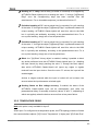
3.3.3 TEMPERATURE PROBE
Note: this option is only available for input 5.
When input 5 is configured as a temperature probe, the ETS topology window will show
the communications objects "[I5] Current Temperature" (2 bytes) and "[I5] Probe Error"
http://www.zennio.com
Technical Support: http://zennioenglish.zendesk.com
40
ACTinBOX CLASSIC HYBRID AD
(1 bit). The first one reports the temperature value measured by the probe connected to
ACTinBOX Classic-Hybrid, while through the second object it is possible to monitor
errors due to a wrong connection of the probe or a defective probe (in such case, the
object will acquire the value "1" and will be sent every 30 seconds). Once the problem
is solved, the error object acquires the value "0" again.
The default configuration screen of the temperature sensor is shown in Figure 22:
Figure 23 Input 5. Temperature probe
The following parameters can be parameterized:
Temperature sensor calibration: allows making an adjustment (by setting a
positive or negative value in tenths of a degree) over the measured
temperature when, due to whatever external factor, a deviation is found
between the measured value and that of the actual temperature of the room.
Temperature sending period: sets the period time (in tens of a second) in
case a cyclical sending of the current temperature through the "[Ix] Current
Temperature" communication object is required. The value “0” disables the
periodical sending.
Send with
a temperature change:
ACTinBOX
Classic-Hybrid will
automatically make an extra sending of the value of the current temperature
to the KNX bus when, due to a temperature increase or decrease, the
difference between two consecutive measurements is found to be greater or
equal than the amount set here (from 0 to 200 tenths of a degree). To disable
this sending, simply set this field to “0”.
Temperature protection: enables the overheating or the overcooling
protection, or both together. Depending on the option selected, one or two
communication objects will be enabled: "[I5] Overheating" and "[I5]
Overcooling", which will show, at any time, if the upper or lower limits have
http://www.zennio.com
Technical Support: http://zennioenglish.zendesk.com
41
ACTinBOX CLASSIC HYBRID AD
been reached (in such case, the value "1" will be sent). These overcooling /
overheating limits need to be defined (in degrees), as well as a, if desired, a
hysteresis value (in tenths of a degree), which will help prevent consecutive
warnings to the bus when the temperature moves continuously around the
parameterized limit.
3.3.4 MOVEMENT DETECTOR
Note: this option is only available for input 6.
The ACTinBOX Classic-Hybrid actuator allows configuring input 6 as a movement
detector, with the possibility of enabling up to 2 detection channels.
Figure 24 Input 6: Movement detector
After enabling the desired channels, the next configuration screen will be shown:
Figure 25 Channel configuration
http://www.zennio.com
Technical Support: http://zennioenglish.zendesk.com
42
ACTinBOX CLASSIC HYBRID AD
For further information on the behaviour and ETS parameterization of the detection
channels, please refer to the specific document “Motion detector”, available at
http://www.zennio.com.
3.4 LOGICAL FUNCTIONS
This option in ACTinBOX Classic-Hybrid makes it possible to perform mathematical or
binary logic operations to incoming values received from the KNX bus, and to send the
result through other communication objects specifically enabled in the actuator for this
purpose.
Up to 5 different and independent logical functions can be enabled, being each of
them capable of carrying out up to 4 operations. To use any of them, it is necessary
to enable it from the following ETS screen, which becomes available after selecting
“Yes” under Logical Functions in the General parameter screen.
Figure 26 Logical functions
To get further information about how to use and parameterize the logical functions,
please refer to the specific document "Logical Functions X5", available at
http://www.zennio.com.
3.5 THERMOSTAT
The ACTinBOX Classic-Hybrid actuator offers the possibility to enable and configure
one thermostat of the type “Zennio Building Thermostat”.
http://www.zennio.com
Technical Support: http://zennioenglish.zendesk.com
43
ACTinBOX CLASSIC HYBRID AD
Figure 27 Thermostat Configuration
To find basic theory about the Zennio thermostat, as well as information about the
related ETS configuration, please refer to the specific document "Zennio Building
Thermostat", available at http://www.zennio.com.
ANNEX I. SLATS PRECISE CONTROL
Zennio actuators allow controlling the movement of shutters, blinds or similar
window/door automated systems, which may be of one of the following types:
Shutter (No slats).
Blind (with slats/lamellas).
Depending on the shutter type, the ACTinBOX Classic-Hybrid application program will
show different options.
This particular section is referred to the parameterization of blinds with slats.
To begin with, it is important to keep in mind the criteria followed by the actuator for
shutter positioning:
The shutter is in the “up” position (0%, in percentage) when it is completely
open.
The shutter is in the “down” position (100%, in percentage) when it is
completely closed.
While the slat positioning criteria is as follows:
http://www.zennio.com
Technical Support: http://zennioenglish.zendesk.com
44
ACTinBOX CLASSIC HYBRID AD
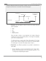
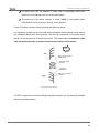
The slats are in the “up” position or “open” (0%, in percentage) when their
position is such that they can only move downwards.
The slats are in the “down” position or “close” (100%, in percentage) when
their position is such that they can only move upwards.
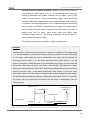
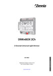
Figure 27 shows a scheme of the positions the slats may adopt.
It is necessary to take into account that shutter actuators control shutter drives without
any feedback about their exact position, and that the movement of the slats relays
entirely on the movement of shutter drive itself. This means that a movement in the
slats will always provoke a certain change in the position of the shutter.
SUN
Slats can only move
downward
Slats can move
upward…
…and also
downward
Slats can only move
upward
Figure 28 Slat positions
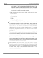
The ETS configuration screen for Blinds with slats is shown next, as well as the details
about the available options:
http://www.zennio.com
Technical Support: http://zennioenglish.zendesk.com
45
ACTinBOX CLASSIC HYBRID AD
Figure 29 Blinds with slats. Configuration screen (ETS)
As shown in Figure 28, for this type of shutters multiple time parameters need to be
parameterized. On the one hand, time parameters referred to the movement of the
blind: “Main Time (shutter length)”, “Security time”, “Are total time up and down
different?” and “Additional time when shutter gets the limit”. All of them were
already explained in Section 3.2.2 of this manual.
On the other hand, time parameters referred to the movement of the slats:
Secondary time (slats length): sets the time, in tenths of a second, the drive
takes to perform a complete slat movement cycle from 0% (completely "up")
to 100% (completely "down"), or vice versa. This time must be manually
measured.
Slats Step Time: sets the time, in tenths of a second, the drive will keep
moving the slats every time it receives the order to perform an up/down step
movement ("[CX] Stop/Step"=0 or 1, respectively), assuming that the blind is
stopped. These step orders allow gradually rotating the slats and modifying
their position (%), which may be very useful to prevent glare, for example
after a change in the position of the sun.
Note: in case of joint-controlling slat step movements of multiple shutter
channels together through the same group address, the time configured for
this parameter is recommended to be slightly greater than N tenths of a
second (where N is the amount of the channels that have been enabled and
http://www.zennio.com
Technical Support: http://zennioenglish.zendesk.com
46
ACTinBOX CLASSIC HYBRID AD
configured as “blind with slats”) in order to ensure that rapidly sent
consecutive orders are properly processed.
Note: times referred to slat movements must be shorter than those configured for blind
movements (usual configuration).
Besides defining these times, it will be necessary to configure the following options,
which are specific for blinds with slats:
Maintain slats position when shutter completes motion?: this option
allows choosing whether the slats should recover their position after the blind
reaches the desired position, or not.
Example:
Suppose the parameter “Maintain slats positioning when shutter completes motion?”
has been enabled. The initial position of the slats is 50% and the initial position of the
blind is 0% (up). An order to lower the blind is received, thus making the blind (and
therefore the slats) start moving downwards, until the position of the blind reaches
100%. At this point, the blind has completed its movement, and ACTinBOX ClassicHybrid will revert the position of the slats by additionally moving the drive until they
reach the position they had before (50%, in this example), thus causing a minor
deviation in the position of the blind.
If parameter “Maintain slats positioning when shutter completes motion?” had not been
enabled, when the position of the blind reaches 100% (down), the slats will maintain
their resulting position after the movement of the blind.
Slats position at Bottom pos. [%]: allows establishing the slats position (in
percentage) when the blind is completely closed (i.e., its position is equal to
100%).
This means that, when the blind stops moving downwards and reaches
100%, the slats will correct their position to the one established by parameter.
Apart from these configuration options, it is necessary to define the "Slats specific
position" for those enabled functions where particular positions are required to be
parameterized. These functions are:
http://www.zennio.com
Technical Support: http://zennioenglish.zendesk.com
47
ACTinBOX CLASSIC HYBRID AD
Scenes. “Response: Specific position”. The positions of the blind and the
slats (in percentage) can be configured independently.
Alarms. “Response: Specific position”. The same as above.
Direct positioning. Independent configuration of positions 1 or 2
(depending on the parameterized number), in percentage, of the blind and
the slats.
Start-up configuration. “Initial position: Specific position”. The position
percentages of the blind and slats can be configured independently.
To obtain further information about the configuration and options of the functions of the
shutter channels, please refer to the section 3.2.2 of this manual.
http://www.zennio.com
Technical Support: http://zennioenglish.zendesk.com
48
ACTinBOX CLASSIC HYBRID AD
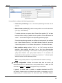
ANNEX II. COMMUNICATION OBJECTS
Column RESET shows the values of the communication objects after a bus failure. However, this does not necessarily imply that such values are sent to the bus.
VALUES
NUMBER
SIZE
I/O
FLAGS
DATA TYPE (DPT)
0
1 Byte
I
C--W-
[18.1] DPT_SceneControl
0-63 (run)
128-191 (learn)
-
-
Scenes (Individual Outputs)
0-63(Run 1-64); 128-191(Learn)
-
-
Scenes (Shutter Channels)
0-63(Run 1-64); 128-191(Learn)
N.O. (0=Open Relay; 1=Close)
RANGE
1ST TIME
NAME
RESET
FUNCTION
1 Byte
I
C--W-
[18.1] DPT_SceneControl
0-63 (run)
128-191 (learn)
1 Bit
I
C--W-
[1.001] DPT_Switch
0/1
Parameteriz.
Parameteriz.
[Ox] ON/Off
1 Bit
I
C--W-
[1.001] DPT_Switch
0/1
Parameteriz.
Parameteriz.
[Ox] ON/Off
N.C. (0=Close Relay; 1=Open)
6-9
1 Bit
O
CTR--
[1.001] DPT_Switch
0/1
Parameteriz.
Parameteriz.
[Ox] Status
0=Output Off; 1=Output ON
10-13
1 Bit
I
C--W-
[1.001] DPT_Switch
0/1
-
Last
[Ox] Timer
0=to turn Off; 1=to turn ON
14-17
1 Bit
I
C--W-
Start/stop
0/1
-
Last
[Ox] Flashing
1=Start Flashing; 0=End Flash.
18-21
1 Bit
I
C--W-
[1.003] DPT_Enable
0/1
0
Last
[Ox] Block
1=Block; 0=Unblock
1 Bit
I
C--W-
[1.5] DPT_Alarm
0/1
-
Last
[Ox] Alarm
0=Alarm; 1=No Alarm
1 Bit
I
C--W-
[1.5] DPT_Alarm
0/1
-
Last
[Ox] Alarm
1=Alarm; 0=No Alarm
1
2-5
22-25
26-29
1 Bit
I
C--W-
[1.16] DPT_Ack
0/1
0
Last
[Ox] Unfreeze Alarm
Alarm=0 + Unf.=1 -> End Alarm
30
1 Bit
I
C--W-
[1.007] DPT_UpDown
0/1
0
Last
[CA] Move
0=Up Shutter; 1=Down Shutter
31
1 Bit
I
C--W-
[1.007] DPT_UpDown
0/1
0
Last
[CA] Reverse Movement
0=Down Shutter; 1=Up Shutter
32
1 Bit
I
C--W-
[1.007] DPT_UpDown
0/1
0
Last
[CB] Move
0=Up Shutter; 1=Down Shutter
33
1 Bit
I
C--W-
[1.007] DPT_UpDown
0/1
0
Last
[CB] Reverse Movement
0=Down Shutter; 1=Up Shutter
1 Bit
I
C--W-
[1.7] DPT_Step
0/1
0
Last
[CA] Stop
0 or 1 = Stop Shutter
1 Bit
I
C--W-
[1.7] DPT_Step
0/1
0
Last
[CA] Stop/Step
0=Stop/StepUp;
1=Stop/StepDown
1 Bit
I
C--W-
[1.003] DPT_Enable
0/1
0
Last
[CA] Block
1=Block; 0=Unblock
1 Bit
I
C--W-
[1.7] DPT_Step
0/1
0
Last
[CB] Stop
0 or 1 = Stop Shutter
1 Bit
I
C--W-
[1.7] DPT_Step
0/1
0
Last
[CB] Stop/Step
0=Stop/StepUp;
1=Stop/StepDown
34
35
36
37
1 Bit
I
C--W-
[1.003] DPT_Enable
0/1
0
Last
[CB] Block
1=Block; 0=Unblock
38
1 Byte
O
CTR--
[5.001] DPT_Scaling
0-255
0
Last
[CA] Current Shutter Position
0=0%=Top; 255=100%=Bottom
39
1 Byte
O
CTR--
[5.001] DPT_Scaling
0-255
0
Last
[CB] Current Shutter Position
0=0%=Top; 255=100%=Bottom
http://www.zennio.com
Technical Support: http://zennioenglish.zendesk.com
49
ACTinBOX CLASSIC HYBRID AD
VALUES
NUMBER
SIZE
I/O
FLAGS
DATA TYPE (DPT)
40
1 Byte
I
C--W-
[5.001] DPT_Scaling
0-255
0
Parameteriz.
[CA] Shutter Positioning
0=0%=Top; 255=100%=Bottom
41
1 Byte
I
C--W-
[5.001] DPT_Scaling
0-255
0
Parameteriz.
[CB] Shutter Positioning
0=0%=Top; 255=100%=Bottom
1 Bit
I
C--W-
[1.5] DPT_Alarm
0/1
-
Last
[CA] Alarm
0=Alarm; 1=No Alarm
1 Bit
I
C--W-
[1.5] DPT_Alarm
0/1
-
Last
[CA] Alarm
1=Alarm; 0=No Alarm
42
43
44
RANGE
1ST TIME
NAME
RESET
FUNCTION
1 Bit
I
C--W-
[1.5] DPT_Alarm
0/1
-
Last
[CA] Alarm 2
0=Alarm; 1=No Alarm
1 Bit
I
C--W-
[1.5] DPT_Alarm
0/1
-
Last
[CA] Alarm 2
1=Alarm; 0=No Alarm
1 Bit
I
C--W-
[1.5] DPT_Alarm
0/1
-
Last
[CB] Alarm
1=Alarm; 0=No Alarm
1 Bit
I
C--W-
[1.5] DPT_Alarm
0/1
-
Last
[CB] Alarm
0=Alarm; 1=No Alarm
1 Bit
I
C--W-
[1.5] DPT_Alarm
0/1
-
Last
[CB] Alarm 2
0=Alarm; 1=No Alarm
1 Bit
I
C--W-
[1.5] DPT_Alarm
0/1
-
Last
[CB] Alarm 2
1=Alarm; 0=No Alarm
46
1 Bit
I
C--W-
[1.16] DPT_Ack
0/1
0
Last
[CA] Unfreeze Alarm
Alarm=0 + Unf.=1 -> End Alarm
47
1 Bit
I
C--W-
[1.16] DPT_Ack
0/1
0
Last
[CB] Unfreeze Alarm
Alarm=0 + Unf.=1 -> End Alarm
48
1 Bit
I
C--W-
[1.17] DPT_Trigger
0/1
0
Last
[CA] Direct Positioning
1=Go to Position; 0=No Action
49
1 Bit
I
C--W-
[1.17] DPT_Trigger
0/1
0
Last
[CA] Direct Positioning 2
1=Go to Position; 0=No Action
50
1 Bit
I
C--W-
[1.17] DPT_Trigger
0/1
0
Last
[CB] Direct Positioning
1=Go to Position; 0=No Action
51
1 Bit
I
C--W-
[1.17] DPT_Trigger
0/1
0
Last
[CB] Direct Positioning 2
1=Go to Position; 0=No Action
52
1 Bit
I
C--W-
[1.17] DPT_Trigger
0/1
0
Last
[CA] Save Position
1=Save Position; 0=No Action
53
1 Bit
I
C--W-
[1.17] DPT_Trigger
0/1
0
Last
[CA] Save Position 2
1=Save Position; 0=No Action
54
1 Bit
I
C--W-
[1.17] DPT_Trigger
0/1
0
Last
[CB] Save Position
1=Save Position; 0=No Action
55
1 Bit
I
C--W-
[1.17] DPT_Trigger
0/1
0
Last
[CB] Save Position 2
1=Save Position; 0=No Action
56
1 Byte
O
CTR--
[5.001] DPT_Scaling
0-255
0
Parameteriz.
[CA] Current Slats Position
0=0%=Open; 255=100%=Closed
57
1 Byte
O
CTR--
[5.001] DPT_Scaling
0-255
0
Parameteriz.
[CB] Current Slats Position
0=0%=Open; 255=100%=Closed
58
1 Byte
I
C--W-
[5.001] DPT_Scaling
0-255
0
Parameteriz.
[CA] Slats Positioning
0=0%=Open; 255=100%=Closed
[CB] Slats Positioning
0=0%=Open; 255=100%=Closed
45
59
1 Byte
I
C--W-
[5.001] DPT_Scaling
0-255
0
Parameteriz.
60-65
1 Bit
I
C--W-
[1.003] DPT_Enable
0/1
0
Last
[Ix] Block
1=Input Disabled; 0=Input Free
65
1 Bit
I
C--W-
[1.003] DPT_Enable
0/1
0
Last
[Ix] Block
1=Input Disabled; 0=Input Free
66-71
1 Bit
I/O
CTRW -
[1.001] DPT_Switch
0/1
Parameteriz.
Last
[Ix] [Sensor] Edge
Edge -> Sending of "0" or "1"
1 Bit
I/O
CTRW -
[1.001] DPT_Switch
0/1
0
Last
[Ix] [Short Press] "0"
Short Pr. -> Sending of "0"
1 Bit
I/O
CTRW -
[1.001] DPT_Switch
0/1
1
Last
[Ix] [Short Press] "1"
Short Pr. -> Sending of "1"
1 Bit
I/O
CTRW -
[1.001] DPT_Switch
0/1
0
Last
[Ix] [Short Press] Switching
Short Pr. -> Switching "0/1"
1 Bit
I/O
CTRW -
[1.007] DPT_UpDown
0/1
0
Last
[Ix] [Short Press] Move Up Shutter
Short Pr. -> Sending of 0 (Up)
1 Bit
I/O
CTRW -
[1.007] DPT_UpDown
0/1
1
Last
[Ix] [Short Press] Move Down Shutter
Short Pr. -> Send. of 1 (Down)
1 Bit
I/O
CTRW -
[1.007] DPT_UpDown
0/1
0
Last
[Ix] [Short Press] Move
Short Pr. -> Switching "0/1"
http://www.zennio.com
Technical Support: http://zennioenglish.zendesk.com
50
ACTinBOX CLASSIC HYBRID AD
NUMBER
72-77
78-83
84-89
90
91
92
93
VALUES
SIZE
I/O
FLAGS
DATA TYPE (DPT)
1 Bit
I/O
CTRW -
[1.7] DPT_Step
0/1
0
Last
[Ix] [Short Press] Stop / Step Up Shutter
1 Bit
I/O
CTRW -
[1.7] DPT_Step
0/1
1
Last
[Ix] [Short Press] Stop / Step Down Shutter
Short Pr. -> Sending of "1"
1 Bit
I/O
CTRW -
[1.7] DPT_Step
0/1
0
Last
[Ix] [Short Press] Stop / Step Shutter (switched)
Short Pr. -> Switching "0/1"
1 Bit
I/O
CTRW -
[1.001] DPT_Switch
0/1
1
Last
[Ix] [Short Press] Dimmer ON
Short Pr. -> Sending of 1 (ON)
1 Bit
I/O
CTRW -
[1.001] DPT_Switch
0/1
0
Last
[Ix] [Short Press] Dimmer Off
Short Pr. -> Send. of 0 (Off)
1 Bit
I/O
CTRW -
[1.001] DPT_Switch
0/1
0
Last
[Ix] [Short Press] Dimmer
Short Pr. -> Switching "0/1"
4 Bit
O
CTR--
[3.007] DPT_Control_Dimming
0-15
0
Last
[Ix] [Short Press] Brighter
Sh.Pr.->Bright; Sh.Pr.->Stop
4 Bit
O
CTR--
[3.007] DPT_Control_Dimming
0-15
0
Last
[Ix] [Short Press] Darker
Sh.Pr.->Dark; Sh.Pr.->Stop
4 Bit
O
CTR--
[3.007] DPT_Control_Dimming
0-15
0
Last
[Ix] [Short Press] Brighter/Darker
Sh.Pr->Bright/Dark;Sh.Pr->Stop
1 Byte
O
CTR--
[18.1] DPT_SceneControl
0-63; 128-191
0
Last
[Ix] [Short Press] Run Scene
Short Pr. -> Sending of 0-63
1 Byte
O
CTR--
[18.1] DPT_SceneControl
0-63; 128-191
0
Last
[Ix] [Short Press] Save Scene
Short Pr. -> Send. of 128-191
RANGE
1ST TIME
NAME
RESET
FUNCTION
Short Pr. -> Sending of "0"
1 Bit
I/O
CTRW -
[1.001] DPT_Switch
0/1
0
Last
[Ix] [Long Press] Dimmer On
Long Pr. -> Sending of 1 (ON)
1 Bit
I/O
CTRW -
[1.001] DPT_Switch
0/1
0
Last
[Ix] [Long Press] Dimmer Off
Long Pr. -> Send. of 0 (Off)
1 Bit
I/O
CTRW -
[1.001] DPT_Switch
0/1
0
Last
[Ix] [Long Press] Dimmer On/Off
Long Pr. -> Switching "0/1"
1 Bit
I/O
CTRW -
[1.007] DPT_UpDown
0/1
0
Last
[Ix] [Long Press] Move Up Shutter
Long Pr. -> Sending of 0 (Up)
1 Bit
I/O
CTRW -
[1.007] DPT_UpDown
0/1
0
Last
[Ix] [Long Press] Move Down Shutter
Long Pr. -> Send. of 1 (Down)
1 Bit
I/O
CTRW -
[1.007] DPT_UpDown
0/1
0
Last
[Ix] [Long Press] Move Up/Down Shutter
Long Pr. -> Switching "0/1"
1 Bit
I/O
CTRW -
[1.7] DPT_Step
0/1
0
Last
[Ix] [Long Press] Stop / Step Up Shutter
Long Pr. -> Sending of "0"
1 Bit
I/O
CTRW -
[1.7] DPT_Step
0/1
0
Last
[Ix] [Long Press] Stop / Step Down Shutter
Long Pr. -> Sending of "1"
1 Bit
I/O
CTRW -
[1.7] DPT_Step
0/1
0
Last
[Ix] [Long Press] Stop / Step Shutter (switched)
Long Pr. -> Switching "0/1"
1 Bit
I/O
CTRW -
[1.001] DPT_Switch
0/1
0
Last
[Ix] [Long Press] "0"
Long Pr. -> Sending of "0"
1 Bit
I/O
CTRW -
[1.001] DPT_Switch
0/1
0
Last
[Ix] [Long Press] "1"
Long Pr. -> Sending of "1"
1 Bit
I/O
CTRW -
[1.001] DPT_Switch
0/1
0
Last
[Ix] [Long Press] Switching
Long Pr. -> Switching "0/1"
4 Bit
O
CTR--
[3.007] DPT_Control_Dimming
0-15
0
Last
[I1] [Long Press] Brighter
Lg.Pr.->Bright; Lg.Pr.->Stop
4 Bit
O
CTR--
[3.007] DPT_Control_Dimming
0-15
0
Last
[I1] [Long Press] Darker
Lg.Pr.->Dark; Lg.Pr.->Stop
4 Bit
O
CTR--
[3.007] DPT_Control_Dimming
0-15
0
Last
[I1] [Long Press] Brighter/Darker
Lg.Pr->Bright/Dark;Lg.Pr->Stop
4 Bit
O
CTR--
[3.007] DPT_Control_Dimming
0-15
0
Last
[I2] [Long Press] Brighter
Lg.Pr.->Bright; Lg.Pr.->Stop
4 Bit
O
CTR--
[3.007] DPT_Control_Dimming
0-15
0
Last
[I2] [Long Press] Darker
Lg.Pr.->Dark; Lg.Pr.->Stop
4 Bit
O
CTR--
[3.007] DPT_Control_Dimming
0-15
0
Last
[I2] [Long Press] Brighter/Darker
Lg.Pr->Bright/Dark;Lg.Pr->Stop
4 Bit
O
CTR--
[3.007] DPT_Control_Dimming
0-15
0
Last
[I3] [Long Press] Brighter
Lg.Pr.->Bright; Lg.Pr.->Stop
4 Bit
O
CTR--
[3.007] DPT_Control_Dimming
0-15
0
Last
[I3] [Long Press] Darker
Lg.Pr.->Dark; Lg.Pr.->Stop
4 Bit
O
CTR--
[3.007] DPT_Control_Dimming
0-15
0
Last
[I3] [Long Press] Brighter/Darker
Lg.Pr->Bright/Dark;Lg.Pr->Stop
4 Bit
O
CTR--
[3.007] DPT_Control_Dimming
0-15
0
Last
[I4] [Long Press] Brighter
Lg.Pr.->Bright; Lg.Pr.->Stop
http://www.zennio.com
Technical Support: http://zennioenglish.zendesk.com
51
ACTinBOX CLASSIC HYBRID AD
NUMBER
94
95
96
97
98
99
100
101
VALUES
SIZE
I/O
FLAGS
DATA TYPE (DPT)
4 Bit
O
CTR--
[3.007] DPT_Control_Dimming
0-15
0
Last
[I4] [Long Press] Darker
Lg.Pr.->Dark; Lg.Pr.->Stop
4 Bit
O
CTR--
[3.007] DPT_Control_Dimming
0-15
0
Last
[I4] [Long Press] Brighter/Darker
Lg.Pr->Bright/Dark;Lg.Pr->Stop
RANGE
1ST TIME
RESET
NAME
FUNCTION
4 Bit
O
CTR--
[3.007] DPT_Control_Dimming
0-15
0
Last
[I5] [Long Press] Brighter
Lg.Pr.->Bright; Lg.Pr.->Stop
4 Bit
O
CTR--
[3.007] DPT_Control_Dimming
0-15
0
Last
[I5] [Long Press] Darker
Lg.Pr.->Dark; Lg.Pr.->Stop
4 Bit
O
CTR--
[3.007] DPT_Control_Dimming
0-15
0
Last
[I5] [Long Press] Brighter/Darker
Lg.Pr->Bright/Dark;Lg.Pr->Stop
4 Bit
O
CTR--
[3.007] DPT_Control_Dimming
0-15
0
Last
[I6] [Long Press] Brighter
Lg.Pr.->Bright; Lg.Pr.->Stop
4 Bit
O
CTR--
[3.007] DPT_Control_Dimming
0-15
0
Last
[I6] [Long Press] Darker
Lg.Pr.->Dark; Lg.Pr.->Stop
4 Bit
O
CTR--
[3.007] DPT_Control_Dimming
0-15
0
Last
[I6] [Long Press] Brighter/Darker
Lg.Pr->Bright/Dark;Lg.Pr->Stop
1 Byte
O
CTR--
[18.1] DPT_SceneControl
0-63; 128-191
0
Last
[I1] [Long Press] Run Scene
Long Pr. -> Sending of 0-63
1 Byte
O
CTR--
[18.1] DPT_SceneControl
0-63; 128-191
0
Last
[I1] [Long Press] Save Scene
Long Pr. -> Send. of 128-191
1 Byte
O
CTR--
[18.1] DPT_SceneControl
0-63; 128-191
0
Last
[I2] [Long Press] Run Scene
Long Pr. -> Sending of 0-63
1 Byte
O
CTR--
[18.1] DPT_SceneControl
0-63; 128-191
0
Last
[I2] [Long Press] Save Scene
Long Pr. -> Send. of 128-191
1 Byte
O
CTR--
[18.1] DPT_SceneControl
0-63; 128-191
0
Last
[I3] [Long Press] Run Scene
Long Pr. -> Sending of 0-63
1 Byte
O
CTR--
[18.1] DPT_SceneControl
0-63; 128-191
0
Last
[I3] [Long Press] Save Scene
Long Pr. -> Send. of 128-191
1 Byte
O
CTR--
[18.1] DPT_SceneControl
0-63; 128-191
0
Last
[I4] [Long Press] Run Scene
Long Pr. -> Sending of 0-63
1 Byte
O
CTR--
[18.1] DPT_SceneControl
0-63; 128-191
0
Last
[I4] [Long Press] Save Scene
Long Pr. -> Send. of 128-191
1 Byte
O
CTR--
[18.1] DPT_SceneControl
0-63; 128-191
0
Last
[I5] [Long Press] Run Scene
Long Pr. -> Sending of 0-63
1 Byte
O
CTR--
[18.1] DPT_SceneControl
0-63; 128-191
0
Last
[I5] [Long Press] Save Scene
Long Pr. -> Send. of 128-191
1 Byte
O
CTR--
[18.1] DPT_SceneControl
0-63; 128-191
0
Last
[I6] [Long Press] Run Scene
Long Pr. -> Sending of 0-63
1 Byte
O
CTR--
[18.1] DPT_SceneControl
0-63; 128-191
0
Last
[I6] [Long Press] Save Scene
Long Pr. -> Send. of 128-191
102
1 Bit
I
C--W-
[1.001] DPT_Switch
0/1
-
Last
[LF] (1 bit) Data Entry 1
Binary Data Entry (0/1)
103
1 Bit
I
C--W-
[1.001] DPT_Switch
0/1
-
Last
[LF] (1 bit) Data Entry 2
Binary Data Entry (0/1)
104
1 Bit
I
C--W-
[1.001] DPT_Switch
0/1
-
Last
[LF] (1 bit) Data Entry 3
Binary Data Entry (0/1)
105
1 Bit
I
C--W-
[1.001] DPT_Switch
0/1
-
Last
[LF] (1 bit) Data Entry 4
Binary Data Entry (0/1)
106
1 Bit
I
C--W-
[1.001] DPT_Switch
0/1
-
Last
[LF] (1 bit) Data Entry 5
Binary Data Entry (0/1)
107
1 Bit
I
C--W-
[1.001] DPT_Switch
0/1
-
Last
[LF] (1 bit) Data Entry 6
Binary Data Entry (0/1)
108
1 Bit
I
C--W-
[1.001] DPT_Switch
0/1
-
Last
[LF] (1 bit) Data Entry 7
Binary Data Entry (0/1)
109
1 Bit
I
C--W-
[1.001] DPT_Switch
0/1
-
Last
[LF] (1 bit) Data Entry 8
Binary Data Entry (0/1)
110
1 Bit
I
C--W-
[1.001] DPT_Switch
0/1
-
Last
[LF] (1 bit) Data Entry 9
Binary Data Entry (0/1)
111
1 Bit
I
C--W-
[1.001] DPT_Switch
0/1
-
Last
[LF] (1 bit) Data Entry 10
Binary Data Entry (0/1)
112
1 Bit
I
C--W-
[1.001] DPT_Switch
0/1
-
Last
[LF] (1 bit) Data Entry 11
Binary Data Entry (0/1)
113
1 Bit
I
C--W-
[1.001] DPT_Switch
0/1
-
Last
[LF] (1 bit) Data Entry 12
Binary Data Entry (0/1)
114
1 Bit
I
C--W-
[1.001] DPT_Switch
0/1
-
Last
[LF] (1 bit) Data Entry 13
Binary Data Entry (0/1)
http://www.zennio.com
Technical Support: http://zennioenglish.zendesk.com
52
ACTinBOX CLASSIC HYBRID AD
VALUES
NUMBER
SIZE
I/O
FLAGS
DATA TYPE (DPT)
115
1 Bit
I
C--W-
[1.001] DPT_Switch
0/1
-
Last
[LF] (1 bit) Data Entry 14
Binary Data Entry (0/1)
116
1 Bit
I
C--W-
[1.001] DPT_Switch
0/1
-
Last
[LF] (1 bit) Data Entry 15
Binary Data Entry (0/1)
117
1 Bit
I
C--W-
[1.001] DPT_Switch
0/1
-
Last
[LF] (1 bit) Data Entry 16
Binary Data Entry (0/1)
118
1 Byte
I
C--W-
[5.010] DPT_Value_1_Uncount
0-255
-
Last
[LF] (1 byte) Data Entry 1
1 byte Data Entry (0-255)
119
1 Byte
I
C--W-
[5.010] DPT_Value_1_Uncount
0-255
-
Last
[LF] (1 byte) Data Entry 2
1 byte Data Entry (0-255)
120
1 Byte
I
C--W-
[5.010] DPT_Value_1_Uncount
0-255
-
Last
[LF] (1 byte) Data Entry 3
1 byte Data Entry (0-255)
121
1 Byte
I
C--W-
[5.010] DPT_Value_1_Uncount
0-255
-
Last
[LF] (1 byte) Data Entry 4
1 byte Data Entry (0-255)
122
1 Byte
I
C--W-
[5.010] DPT_Value_1_Uncount
0-255
-
Last
[LF] (1 byte) Data Entry 5
1 byte Data Entry (0-255)
123
1 Byte
I
C--W-
[5.010] DPT_Value_1_Uncount
0-255
-
Last
[LF] (1 byte) Data Entry 6
1 byte Data Entry (0-255)
124
1 Byte
I
C--W-
[5.010] DPT_Value_1_Uncount
0-255
-
Last
[LF] (1 byte) Data Entry 7
1 byte Data Entry (0-255)
125
1 Byte
I
C--W-
[5.010] DPT_Value_1_Uncount
0-255
-
Last
[LF] (1 byte) Data Entry 8
1 byte Data Entry (0-255)
[7.001] DPT_Value_2_Uncount
0 - 65535
-
Last
[9.001] DPT_Value_Temp
0.00 - 120.00
-
Last
[LF] (2 bytes) Data Entry 1
2 bytes Data Entry
[7.001] DPT_Value_2_Uncount
0 - 65535
-
Last
[9.001] DPT_Value_Temp
0.00 - 120.00
-
Last
[LF] (2 bytes) Data Entry 2
2 bytes Data Entry
[7.001] DPT_Value_2_Uncount
0 - 65535
-
Last
[9.001] DPT_Value_Temp
0.00 - 120.00
-
Last
[LF] (2 bytes) Data Entry 3
2 bytes Data Entry
[7.001] DPT_Value_2_Uncount
0 - 65535
-
Last
[9.001] DPT_Value_Temp
0.00 - 120.00
-
Last
[LF] (2 bytes) Data Entry 4
2 bytes Data Entry
[7.001] DPT_Value_2_Uncount
0 - 65535
-
Last
[9.001] DPT_Value_Temp
0.00 - 120.00
-
Last
[LF] (2 bytes) Data Entry 5
2 bytes Data Entry
[7.001] DPT_Value_2_Uncount
0 - 65535
-
Last
[9.001] DPT_Value_Temp
0.00 - 120.00
-
Last
[LF] (2 bytes) Data Entry 6
2 bytes Data Entry
[7.001] DPT_Value_2_Uncount
0 - 65535
-
Last
[9.001] DPT_Value_Temp
0.00 - 120.00
-
Last
[LF] (2 bytes) Data Entry 7
2 bytes Data Entry
[7.001] DPT_Value_2_Uncount
0 - 65535
-
Last
[9.001] DPT_Value_Temp
0.00 - 120.00
-
Last
[LF] (2 bytes) Data Entry 8
2 bytes Data Entry
RANGE
1ST TIME
RESET
NAME
FUNCTION
126
2 Bytes
I
C--W-
127
2 Bytes
I
C--W-
128
2 Bytes
I
C--W-
129
2 Bytes
I
C--W-
130
2 Bytes
I
C--W-
131
2 Bytes
I
C--W-
132
2 Bytes
I
C--W-
133
2 Bytes
I
C--W-
134
1 Bit
O
CTR--
[1.001] DPT_Switch
0/1
0
Last
[LF] Function 1 RESULT (1 bit)
FUNCTION 1 Result
135
1 Bit
O
CTR--
[1.001] DPT_Switch
0/1
0
Last
[LF] Function 2 RESULT (1 bit)
FUNCTION 2 Result
136
1 Bit
O
CTR--
[1.001] DPT_Switch
0/1
0
Last
[LF] Function 3 RESULT (1 bit)
FUNCTION 3 Result
137
1 Bit
O
CTR--
[1.001] DPT_Switch
0/1
0
Last
[LF] Function 4 RESULT (1 bit)
FUNCTION 4 Result
138
1 Bit
O
CTR--
[1.001] DPT_Switch
0/1
0
Last
[LF] Function 5 RESULT (1 bit)
FUNCTION 5 Result
139
1 Byte
O
CTR--
[5.010] DPT_Value_1_Uncount
0-255
0
Last
[LF] Function 1 RESULT (1 byte)
FUNCTION 1 Result
http://www.zennio.com
Technical Support: http://zennioenglish.zendesk.com
53
ACTinBOX CLASSIC HYBRID AD
VALUES
NUMBER
SIZE
I/O
FLAGS
DATA TYPE (DPT)
140
1 Byte
O
CTR--
[5.010] DPT_Value_1_Uncount
0-255
0
Last
[LF] Function 2 RESULT (1 byte)
FUNCTION 2 Result
141
1 Byte
O
CTR--
[5.010] DPT_Value_1_Uncount
0-255
0
Last
[LF] Function 3 RESULT (1 byte)
FUNCTION 3 Result
142
1 Byte
O
CTR--
[5.010] DPT_Value_1_Uncount
0-255
0
Last
[LF] Function 4 RESULT (1 byte)
FUNCTION 4 Result
143
1 Byte
O
CTR--
[5.010] DPT_Value_1_Uncount
0-255
0
Last
[LF] Function 5 RESULT (1 byte)
FUNCTION 5 Result
[7.001] DPT_Value_2_Uncount
0 - 65535
0
Last
[LF] Function 1 RESULT (2 bytes)
FUNCTION 1 Result
FUNCTION 1 Result
144
2 Bytes
O
CTR--
145
2 Bytes
O
CTR--
146
2 Bytes
O
CTR--
147
2 Bytes
O
CTR--
148
2 Bytes
O
CTR--
149
1 Bit
150
1 Bit
151
1 Bit
RANGE
1ST TIME
NAME
RESET
[9.001] DPT_Value_Temp
0.00 - 120.00
0
Last
[LF] Function 1 RESULT (2 bytes)
[7.001] DPT_Value_2_Uncount
0 - 65535
0
Last
[LF] Function 2 RESULT (2 bytes)
FUNCTION 2 Result
[9.001] DPT_Value_Temp
0.00 - 120.00
0
Last
[LF] Function 2 RESULT (2 bytes)
FUNCTION 2 Result
[7.001] DPT_Value_2_Uncount
0 - 65535
0
Last
[LF] Function 3 RESULT (2 bytes)
FUNCTION 3 Result
[9.001] DPT_Value_Temp
0.00 - 120.00
0
Last
[LF] Function 3 RESULT (2 bytes)
FUNCTION 3 Result
[7.001] DPT_Value_2_Uncount
0 - 65535
0
Last
[LF] Function 4 RESULT (2 bytes)
FUNCTION 4 Result
[9.001] DPT_Value_Temp
0.00 - 120.00
0
Last
[LF] Function 4 RESULT (2 bytes)
FUNCTION 4 Result
[7.001] DPT_Value_2_Uncount
0 - 65535
0
Last
[LF] Function 5 RESULT (2 bytes)
FUNCTION 5 Result
[9.001] DPT_Value_Temp
0.00 - 120.00
0
Last
[LF] Function 5 RESULT (2 bytes)
FUNCTION 5 Result
CT---
[1.001] DPT_Switch
0
0
0
Reset 0
Voltage Recovery->Sending of 0
CT---
[1.001] DPT_Switch
1
1
1
Reset 1
Voltage Recovery->Sending of 1
CT---
[1.001] DPT_Switch
0/1
-
0
[I6] Short circuit
1=Short-Circuit;0=No Short-Cir
[I6] Open Circuit
1=Open Circuit;0=No Open Circ.
152
1 Bit
CT---
[1.001] DPT_Switch
0/1
Connection dependant
Connection dependant
153
1 Byte
O
CTR--
[5.001] DPT_Scaling
0-100
Parameteriz.
Last
1 Bit
I
C--W-
[1.001] DPT_Switch
0/1
-
1 Bit
I
C--W-
[1.001] DPT_Switch
0/1
1 Bit
I
C--W-
[1.001] DPT_Switch
0/1
1 Bit
I
C--W-
[1.001] DPT_Switch
154
155
FUNCTION
[I6] Luminosity level
Luminosity on Input 6
0
[I6][Ch. 1] Channel block
1=Block, 0=Unblock
-
1
[I6][Ch. 1] Channel enabling
1=[1.003] DPT_Enable, 0=Disable
-
0
[I6][Ch. 2] Channel block
1=Block, 0=Unblock
0/1
-
1
[I6][Ch. 2] Channel enabling
1=[1.003] DPT_Enable, 0=Disable
According to parameters
156
1 Bit
CT---
[1.001] DPT_Switch
0/1
Parameteriz.
Parameteriz.
[I6][Ch. 1] Detection Status
157
1 Bit
CT---
[1.001] DPT_Switch
0/1
Parameteriz.
Parameteriz.
[I6][Ch. 2] Detection Status
According to parameters
158
1 Byte
I
C--W-
[18.1] DPT_SceneControl
0-63
-
Last
[I6][Ch. 1] Scene Reception
0-63 (Run Scene 1-64)
159
1 Byte
I
C--W-
[18.1] DPT_SceneControl
0-63
-
Last
[I6][Ch. 2] Scene Reception
0-63 (Run Scene 1-64)
160
1 Byte
CT---
[18.1] DPT_SceneControl
0-63
Parameteriz.
Parameteriz.
[I6][Ch. 1] Scene Sending
0-63 (Send Scene 1-64)
161
1 Byte
CT---
[18.1] DPT_SceneControl
0-63
Parameteriz.
Parameteriz.
[I6][Ch. 2] Scene Sending
0-63 (Send Scene 1-64)
162
2 Bytes
CT---
[9.001] DPT_Value_Temp
-273 - 670760
Parameteriz.
Parameteriz.
[I5] Current temperature
Temperature sensor value
163
1 Bit
CT---
[1.001] DPT_Switch
0/1
0
Last
[I5] Overcooling
1=Overcooling;0=No Overcooling
164
1 Bit
CT---
[1.001] DPT_Switch
0/1
0
Last
[I5] Overheating
1=Overheating;0=No Overheating
165
1 Bit
CTR--
[1.001] DPT_Switch
0/1
Connection dependant
Connection dependant
[I5] Probe Error
1=Error;0=No Error
O
http://www.zennio.com
Technical Support: http://zennioenglish.zendesk.com
54
ACTinBOX CLASSIC HYBRID AD
VALUES
NUMBER
SIZE
I/O
FLAGS
DATA TYPE (DPT)
166
2 Bytes
I
C--W-
[9.001] DPT_Value_Temp
-273 - 670760
25
Last
[T1] Temperature Source 1
External Sensor Measure
167
2 Bytes
I
C--W-
[9.001] DPT_Value_Temp
-273 - 670760
25
Last
[T1] Temperature Source 2
External Sensor Measure
C--W-
[20.102] DPT_HVACMode
0=Confort;
1=Standby;
3=Economy;
4=Building Protection
Parameteriz.
Parameteriz.
[T1] Special Mode
1-byte HVAC Mode
168
169
170
171
1 Byte
I
RANGE
1ST TIME
NAME
RESET
FUNCTION
1 Bit
I
C--W-
[1.001] DPT_Switch
0/1
0
Last
[T1] Special Mode: comfort
0=Off; 1=On
1 Bit
I
C--W-
[1.17] DPT_Trigger
0/1
0
Last
[T1] Special Mode: comfort
0=Nothing; 1=Trigger
1 Bit
I
C--W-
[1.001] DPT_Switch
0/1
0
Last
[T1] Special Mode: standby
0=Off; 1=On
1 Bit
I
C--W-
[1.17] DPT_Trigger
0/1
0
Last
[T1] Special Mode: standby
0=Nothing; 1=Trigger
1 Bit
I
C--W-
[1.001] DPT_Switch
0/1
0
Last
[T1] Special Mode: economy
0=Off; 1=On
1 Bit
I
C--W-
[1.17] DPT_Trigger
0/1
0
Last
[T1] Special Mode: economy
0=Nothing; 1=Trigger
1 Bit
I
C--W-
[1.001] DPT_Switch
0/1
0
Last
[T1] Special Mode: protection
0=Off; 1=On
1 Bit
I
C--W-
[1.17] DPT_Trigger
0/1
0
Last
[T1] Special Mode: protection
0=Nothing; 1=Trigger
173
1 Bit
I
C--W-
[1.19] DPT_Window_Door
0/1
0
Last
[T1] Window Status (input)
0=Closed; 1=Open
174
1 Bit
I
C--W-
[1.17] DPT_Trigger
0/1
0
0
[T1] Comfort Prolongation
0=Nothing; 1=Timed Comfort
1 Byte
O
CTR--
[20.102] DPT_HVACMode
0-255
Parameteriz.
Last
[T1] Special Mode Status
1-byte HVAC Mode
2 Bytes
I
C--W-
[9.001] DPT_Value_Temp
5 - 45
Parameteriz.
Last
[T1] Basic Setpoint
Reference setpoint
172
175
176
2 Bytes
I
C--W-
[9.001] DPT_Value_Temp
5 - 45
Parameteriz.
Last
177
1 Bit
I
C--W-
[1.7] DPT_Step
0/1
0
Parameteriz.
178
2 Bytes
I
C--W-
[9.002] DPT_Value_Tempd
-10 - 10
0
Last
[T1] Setpoint Offset
Float Offset value
179
2 Bytes
O
CTR--
[9.001] DPT_Value_Temp
5 - 45
25
Last
[T1] Setpoint Status
Current setpoint
180
2 Bytes
O
CTR--
[9.001] DPT_Value_Temp
5 - 45
Parameteriz.
Last
[T1] Basic Setpoint Status
Current basic setpoint
181
2 Bytes
O
CTR--
[9.002] DPT_Value_Tempd
-10 - 10
0
Last
[T1] Setpoint Offset Status
Current setpoint Offset
182
[T1] Setpoint
Thermostat setpoint input
[T1] Setpoint Step
0=-0.5ºC; 1=+0.5ºC
1 Bit
I
C--W-
[1.15] DPT_Reset
0/1
0
Parameteriz.
[T1] Offset Reset
Reset Offset
1 Bit
I
C--W-
[1.15] DPT_Reset
0/1
0
Parameteriz.
[T1] Setpoint Reset
Reset setpoint to default
183
1 Bit
I
C--W-
[1.100] DPT_Heat_Cool
0/1
Parameteriz.
Last
[T1] Mode
0 = Cool; 1 = Heat
184
1 Bit
O
CTR--
[1.100] DPT_Heat_Cool
0/1
Parameteriz.
Last
[T1] Mode Status
0 = Cool; 1 = Heat
185
1 Bit
I
C--W-
[1.100] DPT_Heat_Cool
0/1
Parameteriz.
Last
[T1] On/Off
0=Off; 1=On
186
1 Bit
O
CTR--
[1.001] DPT_Switch
0/1
Parameteriz.
Last
[T1] On/Off
0=Off; 1=On
1 Bit
O
CTR--
[1.001] DPT_Switch
0/1
0
Last
[T1] Control Variable (Cool)
PI Control (PWM)
1 Bit
O
CTR--
[1.001] DPT_Switch
0/1
0
Last
[T1] Control Variable (Cool)
2-Point Control
187
188
189
1 Bit
O
CTR--
[1.001] DPT_Switch
0/1
0
Last
[T1] Control Variable (Heat)
PI Control (PWM)
1 Bit
O
CTR--
[1.001] DPT_Switch
0/1
0
Last
[T1] Control Variable (Heat)
2-Point Control
1 Byte
O
CTR--
[5.001] DPT_Scaling
0-100
0
Last
[T1] Control Variable (Cool)
PI Control (Continuous)
http://www.zennio.com
Technical Support: http://zennioenglish.zendesk.com
55
ACTinBOX CLASSIC HYBRID AD
VALUES
NUMBER
SIZE
I/O
FLAGS
DATA TYPE (DPT)
190
1 Byte
O
CTR--
[5.001] DPT_Scaling
0-100
0
Last
[T1] Control Variable (Heat)
191
1 Bit
O
CTR--
[1.001] DPT_Switch
0/1
0
Last
[T1] Additional Cool
Temp >= (Setpoint+Band) => "1"
192
1 Bit
O
CTR--
[1.001] DPT_Switch
0/1
0
Last
[T1] Additional Heat
Temp <= (Setpoint-Band) => "1"
http://www.zennio.com
RANGE
1ST TIME
NAME
RESET
FUNCTION
PI Control (Continuous)
Technical Support: http://zennioenglish.zendesk.com
56
Join and send us your inquiries
about Zennio devices:
http://zennioenglish.zendesk.com
Zennio Avance y Tecnología S.L.
C/ Río Jarama, 132. Nave P-8.11
45007 Toledo (Spain).
Tel. +34 925 232 002.
Fax. +34 925 337 310.
www.zennio.com
[email protected]