1
A760 Two-Color
A794 Thermal Receipt Printer
Owner’s Guide
Made under one or more of the following U.S. patents: 4886381, 5579043, 5613787, 5651624,
5713678, 5752779, 5789916, 5800080, 5879090, 5887999, 5975776, 6027266, 6085973,
6089450, 6129465, 6155483, 6404452, 6486902, 6504331, 5749277, 6722754, 6739773,
6784909.
A794-D100
2
Federal Communications Commission (FCC) Radio Frequency Interference Statement Warning
Changes or modifications to this unit not expressly approved by the party responsible for compliance could void the user’s authority to operate the
equipment.
Note
This equipment has been tested and found to comply with the limits for a Class A digital device, pursuant to Part 15 of the FCC Rules. These limits are
designed to provide reasonable protection against harmful interference when the equipment is operated in a commercial environment. This equipment
generates, uses, and can radiate radio frequency energy and, if not installed and used in accordance with the instruction manual, may cause harmful
interference to radio communications. Operation of this equipment in a residential area is likely to cause harmful interference in which case the user will be
required to correct the interference at his own expense.
Information to the User
This equipment must be installed and used in strict accordance with the manufacturer’s instructions. However, there is no guarantee that interference to
radio communications will not occur in a particular commercial installation. If this equipment does cause interference, which can be determined by turning
the equipment off and on, the user is encouraged to contact TPG, Inc. immediately.
TPG, Inc. is not responsible for any radio or television interference caused by unauthorized modification of this equipment or the substitution or attachment of
connecting cables and equipment other than those specified by TPG, Inc. The correction of interferences caused by such unauthorized modification,
substitution or attachment will be the responsibility of the user.
In order to ensure compliance with the Product Safety, FCC and CE marking requirements, you must use the power supply, power cord, and interface
cable which are sold for use with this product or which meet the following parameters:
Power Supply
UL Listed (QQGQ), Class 2 power supply with SELV (Secondary Extra Low Voltage), non-energy hazard output, limited energy source, input rated 100240 Vac, 1.5/0.8 A, 50/60 Hz, output rated 24 Vdc, 2.3 A for 55 watt unit; 100-240 Vac, 2.0A, 50/60 Hz, output rate 24 Vdc, 3.125 A for 75 watt unit.
Use of this product with a power supply other than the TPG, Inc. power supply will require you to test the power supply and TPG, Inc. printer for FCC and
CE mark certification.
Communication Interface Cable
A shielded (360 degree) interface cable must be used with this product. The shield must be connected to the frame or earth ground connection or earth
ground reference at EACH end of the cable.
Use of a cable other than described here will require that you test the cable with the TPG, Inc. printer and your system for FCC and CE mark certification.
Power Cord
A UL listed, detachable power cord must be used. For applications where the power supply module may be mounted on the floor, a power cord with Type
SJT marking must be used. For applications outside the US, power cords which meet the particular country’s certification and application requirements
should be used.
Use of a power cord other than described here may result in a violation of safety certifications which are in force in the country of use.
Industry Canada (IC) Radio Frequency Interference Statement
This Class A digital apparatus meets all requirements of the Canadian Interference-Causing Equipment Regulations.
Cet appareil numérique de la classe A respecte toutes les exigences du Règlement sur le matériel brouilleur du Canada.
Voluntary Control Council for Interference (VCCI) Radio Frequency Interference Statement
This is a Class A product based on the standard of the Voluntary Control
Council for Interference by Information Technology Equipment (VCCI). If this
equipment is used in a domestic environment, radio disturbance may arise.
When such trouble occurs, the user may be required to take corrective actions.
Disclaimer
Information in this document is subject to change without notice. Consult your TPG, Inc. sales representative for information that is applicable and current.
TPG, Inc. reserves the right to improve products as new technology, components, software, and firmware become available.
No part of this document may be reproduced, transmitted, or translated in any form or by any means, electronic or mechanical, for any purpose without the
express written permission of TPG, Inc.
Copyright
Copyright © 2004 by TPG, Inc.
950 Danby Road, Ithaca, New York 14850, USA. All rights reserved. Printed in USA. Confidential, Unpublished. Property of TPG, Inc.
Trademarks
TPG, Inc.™ is a trademark of TPG, Inc. and its subsidiaries.
Microsoft, Windows NT are registered Trademarks of Microsoft Corporation in the U.S.A. and/or other countries.
Inside Out Networks, Inside Out, EPIC, and Edgeport are trademarks of Inside Out Networks.
All other trademarks and registered trademarks are the property of their respective holders.
Patents
Made under one or more of the following U.S. patents: 4886381, 5579043, 5613787, 5651624, 5713678, 5752779, 5789916, 5800080, 5879090, 5887999,
5975776, 6027266, 6085973, 6089450, 6129465, 6155483, 6404452, 6486902, 6504331, 5749277, 6722754, 6739773, 6784909.
Web Site
http://www.TPGprinters.com
A794 Thermal Receipt Printer: Owner’s Guide
189-9200250 Rev. C
A794-D100 10/04
Contents
Contents
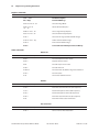
Chapter 1: About the Printer ............................................................. 5
Description of Printer ....................................................................... 5
Models Available ............................................................................... 6
Model Identification ................................................................................................. 6
Communication Interfaces .................................................................................... 6
Features .............................................................................................. 7
Options ................................................................................................ 7
Chapter 2: Using the Printer .............................................................. 9
Unpack the Printer ............................................................................ 9
Remove the Starter Paper Roll Supports ....................................................... 10
Choose a Location ......................................................................... 11
On a Flat Surface ..................................................................................................... 11
Connect the Cables ........................................................................ 12
Communication Cable ......................................................................................... 12
Cash Drawer Cables .............................................................................................. 13
Power Supply Cable .............................................................................................. 13
Printer Controls .............................................................................. 14
Reset Button ............................................................................................................. 14
Paper Feed Button ................................................................................................. 14
LED ................................................................................................................................ 14
Tone .............................................................................................................................. 15
Loading Receipt Paper .................................................................. 16
To Load the Paper ................................................................................................... 16
Configuring the Printer ................................................................ 19
Troubleshooting the Printer ........................................................ 21
Printer Tone and Green LED ............................................................................... 21
Printing Problems ................................................................................................... 22
Printer Does Not Function .................................................................................. 22
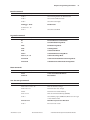
Chapter 3: Media and Supplies Guide .......................................... 23
Ordering Thermal Paper ................................................................ 23
Thermal Paper Specifications ............................................................................ 23
Manufacturers .......................................................................................................... 23
How to Order ............................................................................................................ 23
Ordering Miscellaneous Supplies ............................................... 24
Ordering Cash Drawers ........................................................................................ 24
Ordering Power Supply and Power Cord ..................................................... 24
Ordering Communication Cables .................................................................... 25
Chapter 4: Print Specifications ....................................................... 27
Characters ........................................................................................ 27
Print Modes ............................................................................................................... 27
Size ............................................................................................................................... 27
Paper Specifications ...................................................................... 28
Print Zones ...................................................................................... 28
Print Zones for 80 mm Paper ............................................................................ 28
A794-D100 10/04
189-9200250 Rev. C
A794 Thermal Receipt Printer: Owner’s Guide
3
4
Contents
Print Zones for 82.5 mm Paper ........................................................................ 30
Print Density and Density of Receipt Print Lines .................... 31
Duty Cycle Restrictions (Printing Solid Blocks) ....................... 32
Allowable duty cycle ............................................................................................. 32
Character Sets ................................................................................. 33
Code Page 437 ........................................................................................................ 33
Code Page 737 ........................................................................................................ 34
Code Page 850 ........................................................................................................ 35
Code Page 852 ........................................................................................................ 36
Code Page 858 ........................................................................................................ 37
Code Page 860 ........................................................................................................ 38
Code Page 863 ........................................................................................................ 39
Code Page 865 ........................................................................................................ 40
Code Page 866 ........................................................................................................ 41
Code Page 874 ........................................................................................................ 42
Code Page 1252 ..................................................................................................... 43
Chapter 5: Communication Interface ............................................ 45
Communication Overview ............................................................ 45
Interface ..................................................................................................................... 45
Sending Commands .............................................................................................. 45
RS-232C Interface ............................................................................ 46
Print Speed and Timing ........................................................................................ 46
XON/XOFF Protocol ............................................................................................... 47
DTR/DSR Protocol ................................................................................................... 48
RS-232C Technical Specifications ..................................................................... 48
Power Connector ................................................................................................... 49
Cash Drawer Connector ...................................................................................... 49
RS-232C Settings .................................................................................................... 50
Parallel Interface ............................................................................ 51
IEEE Bi-directional Parallel connector ............................................................. 51
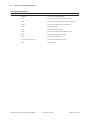
Chapter 6: Programming Information .......................................... 53
Command Conventions ................................................................ 53
List of Commands and Location ................................................. 54
By Command Code ............................................................................................... 54
By Function ................................................................................................................ 58
Comparisons ................................................................................... 63
Command Descriptions ................................................................ 64
Printer Function Commands .............................................................................. 64
Vertical Positioning and Print Commands .................................................... 71
Horizontal Positioning Commands ................................................................. 75
Print Characteristics Commands ...................................................................... 82
Graphics Commands ............................................................................................. 95
Status Commands ................................................................................................ 104
Bar Code Commands ......................................................................................... 124
Page Mode Commands .................................................................................... 127
Macro Commands ............................................................................................... 133
User Data Storage Commands ....................................................................... 135
Flash Download Commands ........................................................................... 138
A794 Thermal Receipt Printer: Owner’s Guide
189-9200250 Rev. C
A794-D100 10/04
Chapter 1: About this Guide
5
Chapter 1: About this Guide
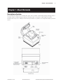
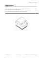
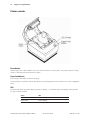
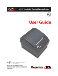
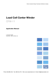
Description of printer
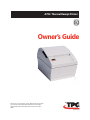
The A794 thermal receipt printer is extremely fast, quiet, and very reliable. With thermal printing technology, there is
no ribbon cassette to change and paper loading is extremely simple. The printer is small enough to fit almost
anywhere and is easy to use. Receipts exit from the top and there is no journal; as it is kept electronically by the host
system.
A794-D100 10/04
189-9200250 Rev. C
A794 Thermal Receipt Printer: Owner’s Guide
6
Chapter 1: About the Printer
Models available
There are several models of the printer, depending on the communication interface and the combination of options
selected.
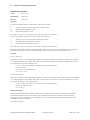
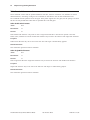
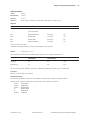
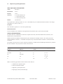
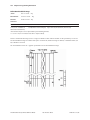
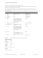
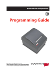
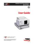
Model identification
See the sample below to determine the configuration of the printer by the printer ID number.
A794 Thermal Receipt Printer: Owner’s Guide
189-9200250 Rev. C
A794-D100 10/04
Chapter 1: About the Printer
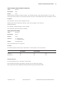
Features
Interfaces
RS-232C, Parallel, USB, Ethernet
Memory/Firmware
512K Flash Memory, History EEROM, 4K Buffer (see “Options” for additional memory.)
Resident Character Sets
PC Code Page 437 (US), PC Code Page 850 (Multilingual), PC Code Page 852; Code Pages
737, 865, 858, 860, 863, 866, 874, and 1252.
Integrated Bar Codes
Code 39, UPC-A, UPC-E, JAN8 (EAN), JAN13 (EAN), Interleaved 2 of 5, Codabar, Code 93,
Code 128, EAN 128, PDF-417 (two-dimensional).
Print
Host-selectable 44 or 56 columns of print on 80 mm wide thermal paper.
Print Resolution
8 dots/mm
Speed
Up to 130 mm/second throughput.
Human Interface
Speaker for software-generated tone. Drop-in paper loading. Configuration Menu for
easy configuration.
Cash Drawer Driver
Connector for one or two cash drawers (use a “Y” cord for two drawers.)
Options
•
Knife (Cutter)
•
Power Supply: 55 Watt/75 Watt
•
Power Cords: US, SEV, UK AC Cord, and Australia AC Cord
•
1MB memory
•
Paper Low Sensor
•
Paper Width
•
82.5 mm
•
80 mm
•
Interface Boards
•
RS 232C
•
IEEE Bi-Directional Parallel
•
Ethernet
•
USB
•
Powered USB
A794-D100 10/04
189-9200250 Rev. C
A794 Thermal Receipt Printer: Owner’s Guide
7
8
Chapter 1: About this Guide
This page intentionally left blank.
A794 Thermal Receipt Printer: Owner’s Guide
189-9200250 Rev. C
A794-D100 10/04
Chapter 2: Using the Printer
9
Chapter 2: Using the Printer
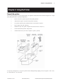
Unpack the printer
Save all packing materials for use if printer needs to be repacked. Check that all items listed were shipped. For a single
pack (multi-packs differ in packing configuration):
•
Printer enclosed in a plastic bag with foam packing material
•
Thermal starter paper roll (inside receipt bucket of printer)
•
Test printout protecting the printhead (inside receipt bucket of printer)
•
Power supply with cable (optional)
•
Installation report card (please complete this form and return to TPG, Inc.)
•
A794 Thermal Receipt Printer: Setup Guide
•
Communication cable, (from host computer to printer, optional)
To report any missing items, or to report a printer that was damaged during shipping, call your supplier or call a TPG,
Inc. representative at 1-877-209-0156.
A794-D100 10/04
189-9200250 Rev. C
A794 Thermal Receipt Printer: Owner’s Guide
10
Chapter 2: Using the Printer
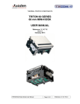
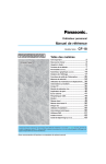
Remove the starter paper roll supports
1. Open the rear cover by pushing up on each side of the cover until it unsnaps. Remove the test printout.
2. Lift the starter paper roll out of the paper bucket and slide the two paper roll supports off.
3. Remove all tape on the leading edge of the roll.
4. Place the starter paper roll back into the bucket so that it unrolls from the bottom.
5. Close the rear cover.
A794 Thermal Receipt Printer: Owner’s Guide
189-9200250 Rev. C
A794-D100 10/04
Chapter 2: Using the Printer
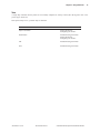
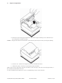
Choose a location
Install the printer flat on a level surface. Always be sure to leave room to open the cover and access the cables.
Note: Position printer in a location that allows access to the cables, room to open the cover and away from traffic
areas to limit the chance of being knocked or damaged.
For more information about setting up the printer, see the A794 Setup Guide.
On a flat surface
A794-D100 10/04
189-9200250 Rev. C
A794 Thermal Receipt Printer: Owner’s Guide
11
12
Chapter 2: Using the Printer
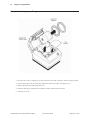
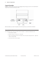
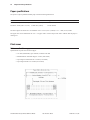
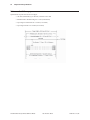
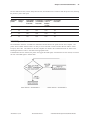
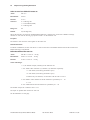
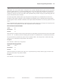
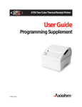
Connect the cables
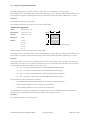
Caution: Connect the cables to the printer before plugging in the power supply. If power is received from the host
computer, turn it off before connecting any cables.
Note: Depending on your printer configuration, the connector panel may vary from the above illustration.
Communication cable
The communication cable connects the printer to the host computer. To install the communication cable:
1. Turn off the host computer.
2. Open the connector cover at the rear of the printer.
3. Attach the communication cable to the connector shown on the back of the printer above. Tighten the
screws to secure the table.
4. Connect the cable to the host computer.
A794 Thermal Receipt Printer: Owner’s Guide
189-9200250 Rev. C
A794-D100 10/04
Chapter 2: Using the Printer
13
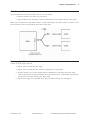
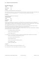
Cash drawer cable
The cash drawer cable connects the printer to one or two cash drawers.
1. Open the connector cover at the rear of the printer.
2. Plug the cable into the cash drawer connector (standard phone jack) located at the rear of the printer.
Note: If your system has two cash drawers, attach a Y-cable to the printer’s cash drawer connector as shown. Leave
some slack in the cord to route through the strain relief at a later time.
Power supply cable
Connect the power supply cable last.
1. Plug the power cord into the power supply.
2. Plug the power cord into the power connector located at the rear of the printer.
3. Snap the connector cover closed, ensuring that the communication, cash drawer, and power supply
cables are aligned with the slots provided for each in the connector cover. Verify that the strain relief on
the connector cover aligns with the power supply cable.
4. Plug the power supply into a grounded outlet. The green LED on the top cover will light up.
A794-D100 10/04
189-9200250 Rev. C
A794 Thermal Receipt Printer: Owner’s Guide
14
Chapter 2: Using the Printer
Printer controls
Reset button
Should a paper jam or fault condition occur, press the reset button to reset the printer. the printer performs a start-up
routine, as if having been turned off, then on again.
Paper feed button
Press the paper feed button to advance the paper.
Use this button in conjunction with the reset button to print the diagnostic mode or allow access to the configuration
menu.
LED
The green LED shows the printer status by shining or flashing. A continuous green (non-flashing) LED represents
an “ON”, no-fault condition.
Status
LED
Paper Is Low
Flashes Slowly
Paper Is Out
Flashes Quickly
Knife Jam
Flashes Quickly then Slowly
A794 Thermal Receipt Printer: Owner’s Guide
189-9200250 Rev. C
A794-D100 10/04
Chapter 2: Using the Printer
15
Tone
A single beep indicates that the printer has successfully completed its start-up routine (after having been reset or the
power supply turned on).
If the printer beeps twice, a problem may be indicated.
For more information about
See these“sections”
Paper Feed Button
“Testing the Printer”
“Configuring the Printer”
Reset Button
“Troubleshooting the Printer”
“Testing the Printer”
“Configuring the Printer”
LED
“Troubleshooting the Printer”
Tone
“Troubleshooting the Printer”
A794-D100 10/04
189-9200250 Rev. C
A794 Thermal Receipt Printer: Owner’s Guide
16
Chapter 2: Using the Printer
Loading receipt paper
Change the paper when any of the following conditions occur:
•
Colored stripe appears on the receipt paper; indicating that the paper is low Change the paper as soon as possible to avoid running out of paper part way through a
transaction.
•
Green LED flashes slowly indicating the paper is low Change the paper as soon as possible to avoid running out of paper part way through a
transaction.
•
Green LED flashes quickly; indicating the paper is out Change the paper immediately or data may be lost.
Caution: Do not operate the printer or host computer if the printer runs out of paper. The printer will not operate
without paper, but it may continue to accept data from the host computer. Because the printer cannot print that
additional data, it may be lost.
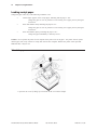
To load the paper:
1. Open the rear cover by lifting up on each side of the cover until it unsnaps.
A794 Thermal Receipt Printer: Owner’s Guide
189-9200250 Rev. C
A794-D100 10/04
Chapter 2: Using the Printer
2. Remove the used paper roll.
3. Tear off the end of the new roll, so that the edge is loose.
A794-D100 10/04
189-9200250 Rev. C
A794 Thermal Receipt Printer: Owner’s Guide
17
18
Chapter 2: Using the Printer
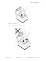
4. Place the new roll into the paper bucket with a few inches of paper extending over the cabinet front (or
top, if the printer is mounted vertically).
Caution: The paper must unroll from the bottom to ensure that the printer will print and to prevent paper jamming.
5. Close the cover. Pull the excess paper across the tear-off blade and remove.
6. Advance the paper, if necessary, by pressing the paper feed button.
Note: In the event of a paper jam, remove the roll and tear a new clean edge. Place the roll into the paper bucket, so
that it unrolls from the bottom of the roll.
For more information about paper jams, see the “Troubleshooting” section of this document.
A794 Thermal Receipt Printer: Owner’s Guide
189-9200250 Rev. C
A794-D100 10/04
Chapter 2: Using the Printer
19
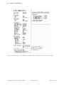
Configuring the printer
The configuration menu allows the user to set general printer parameters. The test prints the settings for several
functions, and partially cuts the paper between each variation.
The printouts may vary for each model. The test ends with a partial cut of the paper, then begins again. A test
printout may use several feet of paper to complete.
To start the test:
1. Set DIP Switch 1 to ON position (down). DIP Switch 2 must always be set to ON position (down).
2. Place paper into the bucket as described in the previous section.
3. Press the reset button.
4. Press and hold the paper feed button while closing the cover.
The printer prints the diagnostics form and the configuration main menu.
Printer pauses and waits for main menu selection to be made. See the sample printout on the next page.
5. Continue through your menu selections until you are asked to: "Save New Parameters?".
Select Yes or No.
a. If answer Yes is selected, return DIP Switch 1 to OFF position (up.)
b. Repeat Steps 3 and 4 above.
Diagnostic printout verifies new settings. See the sample printout on the next page.
6. If answer NO is selected, printer returns to the menu to set parameters again.
A794-D100 10/04
189-9200250 Rev. C
A794 Thermal Receipt Printer: Owner’s Guide
20
Chapter 2: Using the Printer
For more information about poorly printed test printouts, see the “Troubleshooting” section of this document.
A794 Thermal Receipt Printer: Owner’s Guide
189-9200250 Rev. C
A794-D100 10/04
Chapter 2: Using the Printer
21
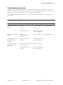
Troubleshooting the printer
The printer is simple and generally trouble-free, but from time to time minor problems may occur. Follow these
procedures to determine the cause and resolution of any problems that the printer may be having. If the procedures
in this section do not correct the problem, contact a TPG, Inc. service representative.
For more detailed and technical troubleshooting, see the “Service Level Troubleshooting” section of the A794
Service Guide.
Printer tone and green LED
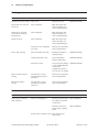
Problem
Possible Causes
What to Do
Where to Go
Green LED, quick continuous
flashing.
Paper out
Put in a new paper roll.
A794 Owner’s Guide
Cover off
Put the cover on.
Knife unable to home
Contact your authorized
service representative.
Green LED, slow continuous
flashing
Paper is low
(if paper low sensor is
installed)
Put in a new paper roll
Printer beeps (two-tone—
low frequency, high
frequency)
Other problems may be
indicated
Contact your authorized
service representative.
Printer beeps and flashes
green LED in various
combinations
Printer has been turned on and
is ready to operate
No action is required.
These all indicate serious
problems
Contact your authorized
service representative.
A794-D100 10/04
189-9200250 Rev. C
A794 Owner’s Guide
A794 Thermal Receipt Printer: Owner’s Guide
22
Chapter 2: Using the Printer
Printing problems
Problem
Possible Causes
What to Do
Where to Go
Colored stripe on the receipt
Paper is low
Change the paper
A794 Owner’s Guide
Receipt does not come out
all the way
Paper is jammed
Open the receipt cover,
inspect the knife, and
clear any jammed paper.
Printer start to print, but
stops while the receipt is
being printed
Paper is jammed
Open the receipt cover,
inspect the knife, and
clear any jammed paper.
Receipt is not cut
Paper is jammed
Open the receipt cover,
inspect the knife, and
clear any jammed paper.
The printer is not configured
for a knife
Contact your authorized
service representative.
Paper roll loaded incorrectly
Check that the paper is
loaded properly.
A794 Owner’s Guide
Thermal printhead is dirty
Use recommended
thermal receipt paper.
A794 Owner’s Guide
Variations in paper
Increase the print density
in “Set Hardware Options”
of the printer
configuration menu to
110% or 120% as needed.
A794 Owner’s Guide
Vertical column of print is
missing
This indicates a serious
problem with the printer
electronics
Contact your authorized
service representative.
One side of receipt is
missing
This indicates a serious
problem wit the printer
electronics
Contact your authorized
service representative.
Print is light or spotty
Printer does not function
Problem
Possible Causes
What to Do
Where to Go
Printer does not function
when turned on
Printer is not plugged in
Check that printer cables
are properly connected
at both ends.
A794 Setup Guide
Check that the host or
power supply is getting
power.
A794 Setup Guide
Receipt cover is not fully closed Close and latch the
receipt cover.
A794 Thermal Receipt Printer: Owner’s Guide
189-9200250 Rev. C
A794-D100 10/04
Chapter 3: Media and Supplies Guide
23
Chapter 3: Media and Supplies Guide
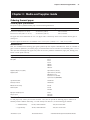
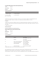
Ordering thermal paper
Thermal paper specifications
The printer requires qualified thermal paper with the following dimensions:
Width
Diameter
Length
80 mm ± .2 mm (3.15 in. ± .02 in.)
90 mm max. (3.54 in.)
322 ft. nominal.
82.5 mm ± .2 mm (3.25 in. ± .02 in.)
90 mm max. (3.54 in.)
322 ft. nominal.
The paper must not be attached at the core. Use paper with a colored stripe at the end to indicate that the paper is
running low.
The above figures are based on a core diameter of 22 ± .5 mm (.87 in.) outside, 11.5 ± .5 mm (.45 in.) inside.
Manufacturers
TPG, Inc. recommends the following paper grades produced by their respective manufacturers. There are a number of
paper converters qualified to provide this paper, provided the POS rolls are from these recommended grades. Use of
other (non-TPG tested/approved) papers may result in excessive printhead contamination, light print, missing print,
and/or void the printer warranty.
Paper Manufacturer
Paper Identification/Grade
Kanzaki Specialty Papers (USA)
Ware, MA
P-300
P-310
P-350
P-354
TO-260
TO-282
TO-381L
Appleton Papers, Inc. (USA)
Appleton, WI
Alpha 400-2.3 (T1030)
Alpha 800-2.3 (T1012A)
POS Plus 600-2.0
Resiste 900-3.0 (T2162)
Alpha 900-3.4 (SUPERIOR)
Jujo Thermal LTD.
Kauttua, Finland
AF50KS-E3
AP62KS-E3
Mitsubishi Int’l Corp.
New York, NY
P-5035
T-8051
TP-8065
Oji Paper Company Ltd
Tokyo, Japan
KF-60
PD-170R
PD-160R
How to order
To order paper rolls, contact your converter of choice. TPG, Inc. can provide the following paper in small lots to
facilitate product evaluation and testing. To order directly from TPG Inc., use the following part numbers:
•
Standard density
50 rolls, 90 mm diameter
TPG, Inc #A152-0034
•
Light density
50 rolls, 90 mm diameter
TPG, Inc. #A152-0035
A794-D100 10/04
189-9200250 Rev. C
A794 Thermal Receipt Printer: Owner’s Guide
24
Chapter 3: Media and Supplies Guide
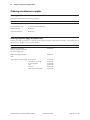
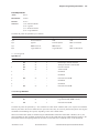
Ordering miscellaneous supplies
Ordering cash drawers
Order cash drawers from the following suppliers:
Cash Drawers
Number
NCR
7052-K657
M-S Cash Drawer Corp.
EP-125 K series, EP-127, EP-102
APG Cash Drawer
Model 322
Indiana Cash Drawer
Model SLD
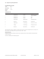
Ordering the power supply and power cords
Contact your sales representative to order the power supply and power cords listed in the table. The numbers are for
reference only. Suppliers may use other numbers.
Item
Type
Number
55W power supply with
attached cable to printer and
U.S. power supply cord
A794-K330
55W power supply, attached
cable
A794-K301
Power supply cord (to outlet)
United States
International (no plug)
United Kingdom
S.E.V.
Australia
International (with plug)
A794 Thermal Receipt Printer: Owner’s Guide
A794-K320
A794-K321
A794-K322
A794-K323
A794-K324
A794-K326
189-9200250 Rev. C
A794-D100 10/04
Chapter 3: Media and Supplies Guide
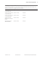
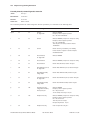
Ordering communication cables
Contact your sales representative or 1 (800) 732-8950 to order the communication cables listed in the table. The
numbers are for reference only. Suppliers may use other numbers.
Communication Cables
Length
Order Number
RS-232C 25-pin male (printer)
to 9-pin female (host)
(2 meters - 6.6 feet)
A141-0005
RS-232C 25-pin male (printer)
to 9-pin female (host)
(6 meters - 19.7 feet)
A141-0006
RS-232C 25-pin female (host)
to 9-pin female (printer)
(3 meters - 9.8 feet)
A141-0008
RS-232C 25-pin female
(ferrite host) to 9-pin female
(printer)
(3 meters - 9.8 feet)
A141-0007
IEEE-1284 Parallel 25-pin
male to 25-pin male
(3 meters - 9.8 feet)
A141-0009
A794-D100 10/04
189-9200250 Rev. C
A794 Thermal Receipt Printer: Owner’s Guide
25
26
Chapter 3: Media and Supplies Guide
This page intentionally left blank.
A794 Thermal Receipt Printer: Owner’s Guide
189-9200250 Rev. C
A794-D100 10/04
Chapter 4: Print Specifications
Chapter 4: Print Specifications
Characters
Print modes
Available print modes:
• Standard
• Compressed
• Double high
• Double wide
• Upside down
• Rotated
• Underlined
•
•
•
•
Reverse
Italic
Bold
Scaled
Size
Character sizes for the standard and compressed mode:
Standard -
15.6 characters per inch
44 characters per line
13 x 24 dots cell size
Compressed -
20.3 characters per inch
56 characters per line
10 x 24 dots cell size
For more information about programming the printer to print in various printer modes, see the “Programming
Information” section of this document.
A794-D100 10/04
189-9200250 Rev. C
A794 Thermal Receipt Printer: Owner’s Guide
27
28
Chapter 4: Print Specifications
Paper specifications
The printer requires qualified thermal paper with the following dimensions:
Width
Diameter
Length
80 mm ± .2 mm (3.15 in. ± .02 in.)
90 mm max. (3.54 in.)
322 ft. nominal
82.5 mm ± .2 mm (3.25 in. ± .02 in.)
90 mm max. (3.54 in.)
322 ft. nominal
The above figures are based on a core diameter of 22 ± .5 mm (.87 in.) outside, 11.5 ± .5 mm (.45 in.) inside.
The paper must not be attached at the core. Use paper with a colored stripe at the end to indicate that the paper is
running low.
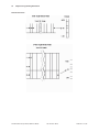
Print zones
Print zones for 80 mm paper
Specifications of print zone for 80 mm paper:
•
576 dots (addressable) @ 8 dots/mm, centered on 80 mm
•
Standard Mode: minimum margins: 2.5 mm (.098 inches)
•
Top margin to manual tear-off: 17.8 mm (0.70 inches)
•
Top margin to knife cut: 19.0 mm (0.75 inches)
A794 Thermal Receipt Printer: Owner’s Guide
189-9200250 Rev. C
A794-D100 10/04
Chapter 4: Print Specifications
29
When printing graphics or logos converted from 6 dot/ mm to 8 dot/ mm, the printable zone is expanded to 598 dots.
A794-D100 10/04
189-9200250 Rev. C
A794 Thermal Receipt Printer: Owner’s Guide
30
Chapter 4: Print Specifications
Print zones for 82.5 mm paper
Specifications of print zone for 82.5 mm paper:
•
640 dots (addressable) @ 8 dots/mm, centered on 82.5 mm
•
Standard mode: minimum margins: 1.0 mm (0.040 inches)
•
Top margin to manual tear-off: 17.8 mm (0.70 inches)
•
Top margin to knife cut: 19.0 mm (0.75 inches)
A794 Thermal Receipt Printer: Owner’s Guide
189-9200250 Rev. C
A794-D100 10/04
Chapter 4: Print Specifications
31
Print density and density of receipt print lines
This function makes it possible to adjust the energy level of the printhead to darken the printout. An adjustment
should only be made when necessary. The factory setting is 100%.
Warning: Choose an energy level no higher than necessary to achieve a dark printout. Failure to observe this rule
may result in a printer service call or voiding of the printer warranty. Consult your TPG, Inc. technical support
specialist if you have any questions.
When the printer prints high density print lines (text or graphics), it automatically slows down.
To change the Print Density:
1. Enter the configuration menu.
2. Select "Set Hardware Options" from the main menu.
"Hardware Options Menu" is printed on the receipt and the question "Set Print Density?" asked.
3. Answer YES (Long click).
A warning is printed, followed by:
Print Density
100%
1 Click
110% (+)
2 Clicks
120% (++)
3 Clicks
Enter code, then hold Button DOWN at least 1 second to validate.
A794-D100 10/04
189-9200250 Rev. C
A794 Thermal Receipt Printer: Owner’s Guide
32
Chapter 4: Print Specifications
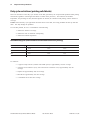
Duty cycle restrictions (printing solid blocks)
There are restrictions on the duty cycle because of the heat generated by the receipt thermal printhead when printing
solid blocks (regardless of the length of the block in relation to the print line). The restrictions are ambient
temperature, the percentage of time (measured against one minute) of continuous solid printing, and the amount of
coverage.
Caution: When the duty cycle approaches the limits shown in the table, the receipt printhead will heat up and shut
down. This may damage the printhead.
To avoid this problem, do one or a combination of the following:
1. Reduce the amount of coverage.
2. Reduce the time of continuous solid printing.
3. Reduce the ambient temperature.
Allowable duty cycle (measured over one minute of continuous printing)
Amount of Solid Coverage
Ambient Temperature
25°C
35° C
50° C
20%
100%
50%
20%
40%
50%
25%
10%
100%
20%
10%
4%
For reference:
•
A typical receipt with text (contains some blank spaces) is approximately 12% dot coverage.
•
A full line of text characters (every cell on the line has a character in it) is approximately 25% dot
coverage.
•
Graphics are approximately 40% dot coverage.
•
Barcodes are approximately 50% dot coverage.
•
A solid black line is 100% dot coverage
A794 Thermal Receipt Printer: Owner’s Guide
189-9200250 Rev. C
A794-D100 10/04
Chapter 4: Print Specifications
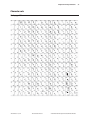
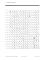
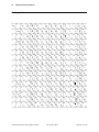
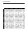
Character sets
Code page 437
A794-D100 10/04
189-9200250 Rev. C
A794 Thermal Receipt Printer: Owner’s Guide
33
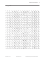
34
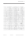
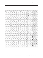
Chapter 4: Print Specifications
Code page 737
A794 Thermal Receipt Printer: Owner’s Guide
189-9200250 Rev. C
A794-D100 10/04
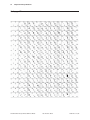
Chapter 4: Print Specifications
Code page 850
A794-D100 10/04
189-9200250 Rev. C
A794 Thermal Receipt Printer: Owner’s Guide
35
36
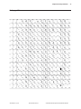
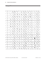
Chapter 4: Print Specifications
Code page 852
A794 Thermal Receipt Printer: Owner’s Guide
189-9200250 Rev. C
A794-D100 10/04
Chapter 4: Print Specifications
Code page 858
A794-D100 10/04
189-9200250 Rev. C
A794 Thermal Receipt Printer: Owner’s Guide
37
38
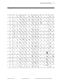
Chapter 4: Print Specifications
Code page 860
A794 Thermal Receipt Printer: Owner’s Guide
189-9200250 Rev. C
A794-D100 10/04
Chapter 4: Print Specifications
Code page 863
A794-D100 10/04
189-9200250 Rev. C
A794 Thermal Receipt Printer: Owner’s Guide
39
40
Chapter 4: Print Specifications
Code page 865
A794 Thermal Receipt Printer: Owner’s Guide
189-9200250 Rev. C
A794-D100 10/04
Chapter 4: Print Specifications
Code page 866
A794-D100 10/04
189-9200250 Rev. C
A794 Thermal Receipt Printer: Owner’s Guide
41
42
Chapter 4: Print Specifications
Code page 874
A794 Thermal Receipt Printer: Owner’s Guide
189-9200250 Rev. C
A794-D100 10/04
Chapter 4: Print Specifications
Code page 1252
A794-D100 10/04
189-9200250 Rev. C
A794 Thermal Receipt Printer: Owner’s Guide
43
44
Chapter 4: Print Specifications
This page intentionally left blank.
A794 Thermal Receipt Printer: Owner’s Guide
189-9200250 Rev. C
A794-D100 10/04
Chapter 5: Communication Interface
45
Chapter 5: Communication Interface
Communication overview
In order for a receipt to be printed, a program must be in place that translates the data from the host computer into a
language that the printer can understand. This program must tell the printer exactly how to print each character. This
chapter describes how to create such a program or modify an existing one.
Interface
In order for the printer to communicate with the host, a communication link must be set up. The printer supports the
RS-232C Serial and IEEE 1284 Parallel interface.
The interfaces have a protocol associated with them that the host must understand and adhere to. Only when the
interface parameters are matched and the proper protocol is used, will the host and the printer be able to
communicate.
For more information about protocol description, see the “RS-232C Interface” section of this document.
Sending Commands
Once the communication link is established, commands can be sent to the printer. This section describes how to send
commands to the printer using DOS and BASIC. This section does not take into account the necessary protocol, but
is meant as a general introduction to how the printer functions.
Using DOS to Send Commands
One way of getting commands to the printer is to send them directly from DOS. For example, the command
COPY CON: COM1:
sets the computer up such that the hexadecimal code corresponding to any key that was pressed would be sent to
the communication port COM1 when the COPY mode is exited. If the printer is connected to COM1, then the data will
go to the printer.
Exit the COPY mode by typing
CTRL Z
and then pressing the ENTER key. Once the computer knows to direct data from any print command to the proper
port, commands can be sent from any software program.
Using BASIC to Send Commands
In BASIC, printer commands are sent as a string of characters that are preceded by the LPRINT command. For
example,
LPRINT CHR$(&H0A)
sends the hexadecimal number 0A to the printer, which causes the printer to print the contents of its print buffer.
Previously sent commands tell the printer exactly how this data should appear on the paper. For example,
LPRINT CHR$(&H12); "ABC"; CHR$(&H0A)
sends the hexadecimal numbers 12 41 42 43 0A to the printer. This causes the printer to set itself to double wide mode
(12), load the print buffer with "ABC" (41 42 43), and finally, print (0A). again, the communication link that the BASIC
program outputs to must be matched to that of the printer.
A794-D100 10/04
189-9200250 Rev. C
A794 Thermal Receipt Printer: Owner’s Guide
46
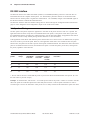
Chapter 5: Communication Interface
RS-232C interface
The RS-232C interface uses either XON/XOFF (software) or DTR/DSR (hardware) protocol to control the flow of
information between the computer and the printer. For XON/XOFF, a particular character is sent back and forth
between the host and the printer to regulate the communication. For DTR/DSR, changes in the DTR/DSR signal on
the RS-232C interface coordinate the information flow.
The RS-232C interface offers the standard settings that are selected through the Configuration Menu described on
page 10 of the "Diagnostics and Configuration" chapter in the A794 Service Guide.
Print Speed and Timing
The fast speed of the printer requires the application to send data to the printer at least as fast as it is printed. The
application must also allow receipt lines to be buffered ahead at the printer, so the printer will be able to print each
line immediately after the preceding line, without stopping to wait for more data. Ideally, the application will send all
the data for an entire receipt without pausing between characters or lines transmitted.
If the application sends data at 9600 baud and pauses between lines for as short a time as 50 milliseconds, the printer
will never be able to print at full speed. However, if the application sends data at 19.2 K baud and does not pause
between lines, the printer will be able to print at its full speed of 2400 lines/minute. The table below shows that with a
pause of 50 milliseconds after each line, the transmit time equals or exceeds the printer process time, slowing down
the printer, regardless of the baud rate.
50 Millisecond Pause after Each Line
Characters
per line
Lines per
receipt
Transmit time
(9600 Baud)
in seconds
20
20
1.40
Transmit time Transmit time Process time
in seconds *
(19.2 K Baud) (115.2 K
Baud) in
in seconds
seconds
1.20
1.03
0.50
20
40
2.80
2.40
2.06
1.00
44
20
1.88
1.44
1.07
0.50
44
40
3.76
2.88
2.15
1.00
* Process Time is the time it would take the printer to process the data if all transmitted data were present. (It is not
the time it takes to print the receipt.)
Example: 20 characters/line, with 20 lines = 0.5 seconds process time for the printer. It takes 1.2 seconds to send the
data to the printer at 19.2K baud speed with a 50ms delay after each line. Thus the printer would have to wait 0.7
seconds longer to receive the data that it could process it if no delays existed and the transmission speed were faster.
A794 Thermal Receipt Printer: Owner’s Guide
189-9200250 Rev. C
A794-D100 10/04
Chapter 5: Communication Interface
47
The next table shows that, with no delay between lines, the transmit time is much less than the process time; allowing
the printer to print at full speed.
50 Millisecond Pause after Each Line
Characters
per line
Lines per
receipt
Transmit time
(9600 Baud)
in seconds
20
20
0.40
Transmit time Transmit time Process time
(19.2 K Baud) (115.2 K
in seconds *
in seconds
Baud) in
seconds
0.20
0.035
0.50
20
40
0.80
0.40
0.070
1.00
44
20
0.88
0.44
0.075
0.50
44
40
1.76
0.88
0.150
1.00
XON/XOFF protocol
The XON/XOFF characters coordinate the information transfer between the printer and the host computer. The
printer sends an XON character when it is ready to receive data and it sends an XOFF character when it cannot
accept any more data. The software on the host computer must monitor the communication link as shown in the
following flowchart in order to send data at the appropriate times.
If XON/XOFF has been selected, the printer also toggles the DTR signal, as described in the next section, but it does
not look at the DSR signal to transmit data.
XON character = hexadecimal 11
A794-D100 10/04
189-9200250 Rev. C
XOFF character = hexadecimal 13
A794 Thermal Receipt Printer: Owner’s Guide
48
Chapter 5: Communication Interface
DTR/DSR protocol
The DTR signal is used to control data transmission to the printer. It is driven low when the printer is ready to
receive data and driven high when it cannot accept any more data. Data is transmitted from the printer after it
confirms that the DSR signal is low.
RS-232C technical specifications
This section describes the pin settings for the connectors and the RS-232C interface parameters. The RS-232C
parameters are selected through the configuration menu feature. The RS-232C parameters must match those of the
host computer.
For more information about RS-232C settings, see the “RS-232C Serial Interface Settings” section in the A794 Service
Guide.
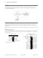
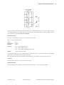
Communication Connectors
The following illustration shows the RS-232C communication connectors and pin assignments. The connectors are
located at the rear of the printer, and are specified as male, DB9, 9-pin D-shell, and female DB25, 25-pin with RTS and
CTS pins connected.
9-pin DB-9 Connector
25-pin DB-25 Connector
Pin Numbers
Function
DSR 6
RTS 7
CTS 8
Not Used 9
1 Not Used
Frame Ground & Shield 1
2 RXD
Transmit Data 2
3 TXD
Receive Data
3
4 DTR
RTS
4
5 Logic Ground
CTS
5
DSR
6
Logic Ground
7
Shell-Frame Ground
Not Used 8
Not Used
9
Not Used 10
Not Used 11
Not Used 12
Not Used 13
A794 Thermal Receipt Printer: Owner’s Guide
189-9200250 Rev. C
Function
14 Not Used
15 Not Used
16 Not Used
17 Not Used
18 Not Used
19 Not Used
20 DTR
21 Not Used
22 Not Used
23 Not Used
24 Not Used
25 Not Used
A794-D100 10/04
Chapter 5: Communication Interface
Power connector
With RS-232C, the printer is always remotely powered. The following illustration shows the power cable connector
and pin assignments. The power cable connector is a 3-pin mini DIN plug and is located at the rear of the printer.
Cash drawer connector
The following illustration shows the pinouts for the cash drawer connector.
The following table shows the pinouts for the cash drawer. The connector can support two cash drawers with a Ycable, and is located at the rear of the printer.
Pin Number
A794-D100 10/04
Cash Drawer Connector
1
Frame Ground
2
Drawer 1 Driver
3
Status Switch +
4
+24 VDC
5
Drawer 2 Driver
6
Status Switch -
189-9200250 Rev. C
A794 Thermal Receipt Printer: Owner’s Guide
49
50
Chapter 5: Communication Interface
RS-232C settings
The printer supports the standard RS-232C settings.
Baud Rate
1200, 2400, 4800, 9600, 19.2 K, 38.4 K, 57.6 K, 115.2 K
Parity
Parity Enabled, Parity Disabled, Even Parity, Odd Parity
Flow Control Method
XON/XOFF, DTR/DSR
Data Reception Errors
Print “?” for Data Errors, Ignore Data Errors
Generally, the printer is shipped with all of the RS-232C parameters preset at the factory. If you need to change any of
these settings, you may do so using the configuration menu feature. This feature prints instructions on the receipt
for changing the RS-232C settings (in addition to other settings).
For more information about changing the RS-232C settings through the configuration menu, see the “Diagnostics
and Configuration” section of the A794 Service Guide.
A794 Thermal Receipt Printer: Owner’s Guide
189-9200250 Rev. C
A794-D100 10/04
Chapter 5: Communication Interface
51
Parallel interface
The printer is also available with an IEEE-1284 parallel interface. The printer configuration must be set to the parallel
interface using the printer's Configuration Menu described in the "Diagnostics and Configuration" section of the
A794 Service Guide.
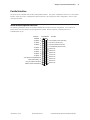
IEEE Bi-directional parallel connector
The following illustration shows the parallel communication connector and pin assignments. The connector is
located at the rear of the printer, and is designated as an IEEE 1284-A receptacle, commonly known as a
D-Subminiature 25 pin.
Pin Numbers
Function
STROBE/ 1
D0 (Data) 2
D1 (Data)
3
D2 (Data)
4
D3 (Data)
5
D4 (Data)
6
D5 (Data)
7
D6 (Data)
8
D7 (Data)
9
ACK/ (Printer Accepted Data) 10
BUSY (Printer Busy) 11
PAP_EX (Paper Exhaust) 12
SELECT (Printer Selected) 13
A794-D100 10/04
189-9200250 Rev. C
Function
14 AUTOFD/ (Auto Paper Feed)
15 FAULT/ (Printer Error)
16 INIT/ (Initialize the Printer)
17 SELECTIN/ (Select Printer)
18
Ground
19 Ground
20 Ground
21 Ground
22 Ground
23 Ground
24 Ground
25 Ground
A794 Thermal Receipt Printer: Owner’s Guide
52
Chapter 5: Communication Interface
This page intentionally left blank.
A794 Thermal Receipt Printer: Owner’s Guide
189-9200250 Rev. C
A794-D100 10/04
Chapter 6: Programming Information
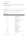
Chapter 6: Programming information
Command conventions
The following information describes how each command is organized:
Name:
Name of command.
ASCII:
The ASCII control code.
Hexadecimal:
The Hexadecimal control code.
Decimal:
The Decimal control code.
Value:
A description of the command operands.
Range:
The upper and lower limits of the command operand.
Default:
The command operand default after printer reset.
Description:
Brief description and summary of the command.
Formulas:
Any formulas used for this command.
Exceptions:
Describes any exceptions to this command, for example: incompatible commands.
Related Information:
Describes related information for this command, for example: bit information.
A794-D100 10/04
189-9200250 Rev. C
A794 Thermal Receipt Printer: Owner’s Guide
53
54
Chapter 6: Programming Information
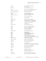
List of commands
Commands control all operations and functions of the printer. This includes selecting the size and placement of
characters and graphics on the receipt to feeding and cutting the paper. The operation of various printers may be
emulated by the commands, including the following:
•
A793
•
A794 Native Mode
•
LEGACY
Any of the commands may be used in any combination to program a host computer to communicate with the printer
(unless otherwise noted).
Some commands listed and described here may not be implemented. They will be identified as "not implemented". If
received, they are ignored and not sent to the print buffer as data. Any non-legal commands are sent to the print
buffer as data.
All items in BOLD are new or have additional functionality when compared to the A793.
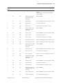
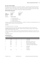
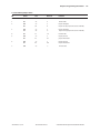
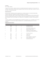
By Command Code
Code (Hexadecimal)
Command
09
Horizontal Tab
0A
Print and Feed One Line
0C
Print and Return to Standard Mode
0D
Print and Carriage Return
10
Clear Printer
10 04 n
Real Time Status Transmission (DLE Sequence)
10 05 n
Real Time Request to Printer (DLE Sequence)
11 n1...n72
Print Raster Graphics
12
Select Double-Wide Characters
13
Select Single-Wide Characters
14 n
Feed n Print Lines
15 n
Feed n Dot Rows
16 n
Add n Extra Dot Rows
17
Print
18
Cancel Print Data in Page Mode
19
Perform Full Knife Cut
1A
Perform Partial Knife Cut
1B (+*.bmp)
Download BMP Logo
1B 07
Generate Tone
1B 0C
Print Data in Page Mode
1B 12
Select 90 Degree Counter-Clockwise Rotated Print
1B 14 n
Set Column
1B 16 n
Select Pitch (Column Width)
A794 Thermal Receipt Printer: Owner’s Guide
189-9200250 Rev. C
A794-D100 10/04
Chapter 6: Programming Information
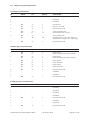
A794-D100 10/04
1B 20 n
Set Right-Side Character Spacing
1B 21 n
Select Print Mode
1B 24 nL nH
Set Absolute Starting Position
1B 25 n
Select or Cancel User-Defined Character Set
1B 26 s c1 c2 n1 d1...nn dn
Define User-Defined Character Set
1B 27 m a0 a1 a2 d1 … dn
Write to User Data Storage
1B 2A m n1 n2 d1...dn
Select Bit Image Mode
1B 2D n
Select or Cancel Underline Mode
1B 2E m n rL rH d1 … dn
Advanced Raster Graphics
1B 32
Set Line Spacing to 1/6 Inch
1B 33 n
Set Line Spacing
1B 34 m a0 a1 a2
Read from User Data Storage
1B 3A 30 30 30
Copy Character Set from ROM to RAM
1B 3D n
Select Peripheral Device (for Multi-Drop)
1B 3F n
Cancel User-Defined Character
1B 40
Initialize Printer
1B 44 [n]...k NUL
Set Horizontal Tab Positions
1B 45 n
Select or Cancel Emphasized Mode
1B 47 n
Select or Cancel Double Strike
1B 49 n
Select or Cancel Italic Print
1B 4A n
Print and Feed Paper
1B 4B n1 n2 d1...dn
Select Single-Density Graphics
1B 4C
Select Page Mode
1B 52 n
Select International Character Set
1B 53
Select Standard Mode
1B 54 n
Select Print Direction in Page Mode
1B 56 n
Select or Cancel 90 Degree Clockwise Rotated Print
1B 57 n1, n2...n8
Set Print Area in Page Mode
1B 59 n1 n2 d1...dn
Select Double-Density Graphics
1B 5B 7D
Switch to Flash Download Mode
1B 5C n1 n2
Set Relative Print Position
1B 61 n
Select Justification
1B 63 33 n
Select Paper Sensors to Output Paper End Signals
1B 63 34 n
Select Sensors to Stop Printing
1B 63 35 n
Enable or Disable Panel Button
1B 64 n
Print and Feed n Lines
1B 69
Perform Full Knife Cut
1B 6A k
Read from Non-Volatile Memory
1B 6D
Perform Partial Knife Cut
1B 70 n p1 p2
Generate Pulse to Open Cash Drawer
1B 73 n1 n2 k
Write to Non-Volatile Memory (NVRAM)
189-9200250 Rev. C
A794 Thermal Receipt Printer: Owner’s Guide
55
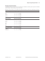
56
Chapter 6: Programming Information
1B 74 n
Select Character Code Table
1B 75 n
Request Alternate Status
1B 75 0
Transmit Peripheral Device Status
1B 76
Transmit Paper Sensor Status
1B 7B n
Select or Cancel Upside Down Print Mode
1D 00
Return Boot Sector Firmware Part Number
1D 01
Return Segment Number Status of Flash Memory
1D 02 n
Select Flash Memory Sector to Download
1D 03 n
Real Time Request to Printer (GS Sequence)
1D 04 n
Real Time Status Transmission (GS Sequence)
1D 05
Real Time Printer Status Transmission
1D 06
Get Firmware CRC
1D 07
Return Micro Processor CRC
1D 0E
Erase All Flash Contents Except Boot Sector
1D 0F
Return Main Program Flash CRC
1D 10 n
Erase Selected Flash Sector
1D 11 aL aH cL cH d1...dn
Download to Active Flash Sector
1D 21 n
Select Character Size
1D 22 n
Select Memory Type (SRAM/Flash) Where to Save Logos
or User-Defined Fonts
1D 22 55 n1 n2
Flash Memory User Sectors Allocation
1D 23 n
Select the Current Logo
1D 24 nL nH
Set Absolute Vertical Print Position in Page Mode
1D 2A n1 n2 d1...dn
Define Downloaded Bit Image
1D 2F m
Print Downloaded Bit Image
1D 3A
Select or Cancel Macro Definition
1D 40 n
Erase User Flash Sector
1D 42 n
Select or Cancel White/Black Reverse Print Mode
1D 48 n
Select Printing Position of HRI Characters
1D 49 n
Transmit Printer ID
1D 49 40 n
Transmit Printer ID, Remote Diagnostics Extension
1D 4C nL nH
Set Left Margin
1D 50 x y
Set Horizontal and Vertical Minimum Motion Units
1D 56 m
Select Cut Mode and Cut Paper
1D 56 m n
Select Cut Mode and Cut Paper
1D 57 nL nH
Set Printing Area Width
1D 5C nL nH
Set Relative Vertical Print Position in Page Mode
1D 5E r t m
Execute Macro
1D 61 n
Select or Cancel Automatic Status Back (ASB)
1D 62 n
Select or Cancel Smoothing Mode
1D 66 n
Select Pitch of HRI Characters
A794 Thermal Receipt Printer: Owner’s Guide
189-9200250 Rev. C
A794-D100 10/04
Chapter 6: Programming Information
A794-D100 10/04
1D 68 n
Select Bar Code Height
1D 6B m d1...dk 00
Print Bar Code
1D 6B m n d1...dn
Print Bar Code
1D 72 n
Transmit Status
1D 77 n
Select Bar Code Width
1D FF
Reset Firmware
1F 04 n
Convert 6 Dots/mm Bitmap to 8 Dots/mm Bitmap
1F 05 n
Select Superscript or Subscript Modes
1F 56
Send Printer Software Version
1F 74
Print Test Form
189-9200250 Rev. C
A794 Thermal Receipt Printer: Owner’s Guide
57
58
Chapter 6: Programming Information
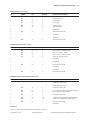
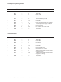
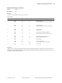
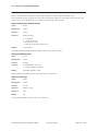
By function
All items in BOLD are new or have additional functionality when compared to the A793.
Printer function commands
Code (hexadecimal)
Command
10
Clear Printer
19
Perform Full Knife Cut
1A
Perform Partial Knife Cut
1B 07
Generate Tone
1B 3D n
Select Peripheral Device (for Multi-Drop)
1B 40
Initialize Printer
1B 63 33 n
Select Paper Sensors to Output Paper End Signals
(Parallel Only)
1B 63 34 n
Select Sensors to Stop Printing
1B 63 35 n
Enable or Disable Panel Buttons
1B 69
Perform Full Knife Cut
1B 6D
Perform Partial Knife Cut
1B 70 n p1 p2
Generate Pulse to Open Cash Drawer
1D 56 m
Select Cut Mode and Cut Paper
1D 56 m n
Select Cut Mode and Cut Paper
1F 74
Print Test Form
Vertical positioning and print commands
Code (hexadecimal)
Command
0A
Print and Feed Paper One Line
0D
Print and Carriage Return
14 n
Feed n Print Lines
15 n
Feed n Dot Rows
16 n
Add n Etra Dot Rows
17
Print
1B 32
Set Line Spacing to 1/6 Inch
1B 33 n
Set Line Spacing
1B 4A n
Print and Feed Paper
1B 64 n
Print and Feed n Lines
1D 50 x y
Set Horizontal and Vertical Minimum Motion Units
A794 Thermal Receipt Printer: Owner’s Guide
189-9200250 Rev. C
A794-D100 10/04
Chapter 6: Programming Information
59
Horizontal positioning commands
Code (hexadecimal)
Command
09
Horizontal Tab
1B 14 n
Set Column
1B 24 nL nH
Set Absolute Starting Position
1B 44 [n] k 00
Set Horizontal Tabs
1B 5C n1 n2
Set Relative Print Position
1B 61 n
Select Justification
1D 4C nL nH
Set Left Margin
1D 57 nL nH
Set Printing Area Width
Print characteristic commands
A794-D100 10/04
Code (hexadecimal)
Command
12
Select Double-Wide Characters
13
Select Single-Wide Characters
1B 12
Select 90 Degree Counter-Clockwise Rotated Print
1B 16 n
Select Pitch (Column Width)
1B 20 n
Set Character Right-Side Spacing
1B 21 n
Select Print Modes
1B 25 n
Select or Cancel User-Defined Character Set
1B 26 s c1 c2 d1…dn
Define User-Defined Characters
1B 2D n
Select or Cancel Underline Mode
1B 3A 30 30 30
Copy Character Set from ROM to RAM
1B 3F n
Cancel User-Defined Characters
1B 45 n
Select or Cancel Emphasized Mode
1B 47 n
Select Double Strike
1B 49 n
Select or Cancel Italic Print
1B 52 n
Select International Character Set and Select Character
Code Table
1B 56 n
Select or Cancel 90 Degrees Clockwise Rotated Print
1B 74 n
Select International Character Set
1B 7B n
Select or Cancel Upside Down Printing Mode
1D 21 n
Select Character Size
1D 42 n
Select or Cancel White/Black Reverse Print Mode
1D 62 n
Select or Cancel Smoothing Mode
1F 05 n
Select Superscript or Subscript Modes
189-9200250 Rev. C
A794 Thermal Receipt Printer: Owner’s Guide
60
Chapter 6: Programming Information
Graphics commands
Code (hexadecimal)
Command
11 n1 … n72
Print Raster Graphics
1B (+*.bmp)
Download BMP Logo
1B 2A m n1 n2 d1…dn
Select Bit Image Mode
1B 2E m n rL rH
d1 … dn
Advanced Raster Garphics
1B 4B n1 n2 d1…dn
Select Single-Density Graphics
1B 59 n1 n2 d1…dn
Select Double-Density Graphics
1D 23 n
Select Current Logo (Downloaded Bit Image)
1D 2A n1 n2 d1…dn]
Define Downloaded Bit Image
1D 2F m
Print Downloaded Bit Image
1F 04 n
Convert 6 Dots/mm Bitmap to 8 Dots/mm Bitmap
Status commands
Batch mode
Code (hexadecimal)
Command
1B 75 0
Transmit Peripheral Device Status
1B 75 n
Request Alternate Status
1B 76
Transmit Paper Sensor Status
1D 49 n
Transmit Printer ID
1D 49 40 n
Transmit Printer ID, Remote Diagnostics Extension
1D 72 n
Transmit Status
1F 56
Send Printer Software Version
Real time
Code (hexadecimal)
Command
10 04 n
Real Time Status Transmission (DLE Sequence)
10 05 n
Real Time Request to Printer (DLE Sequence)
1D 03 n
Real Time Request to Printer (GS Sequence)
1D 04 n
Real Time Status Transmission (GS Sequence)
1D 05
Real Time Printer Status Transmission
Auto status back
Code (hexadecimal)
Command
1D 61 n
Select or Cancel Auto Status Back
A794 Thermal Receipt Printer: Owner’s Guide
189-9200250 Rev. C
A794-D100 10/04
Chapter 6: Programming Information
61
Barcode commands
Code (hexadecimal)
Command
1D 48 n
Select Printing Position for HRI Characters
1D 66 n
Select Pitch for HRI Characters
1D 68 n
Select Bar Code Height
1D 6B m d1…dk 00
or
1D 6B m n d1…dn
Print Bar Code
1D 77 n
Select Bar Code Width
Page mode commands
Code (hexadecimal)
Command
0C
Print and Return to Standard Mode
18
Cancel Print Data in Page Mode
1B 0C
Print Data in Page Mode
1B 4C
Select Page Mode
1B 53
Select Standard Mode
1B 54 n
Select Print Direction in Page Mode
1B 57 n1, n2…n8
Set Print Area in Page Mode
1D 24 nL nH
Set Absolute Vertical Print Position in Page Mode
1D 5C nL nH
Set Relative Vertical Print Position in Page Mode
Macro commands
Code (hexadecimal)
Command
1D 3A
Select or Cancel Macro Definition
1D 5E r t m
Execute Macro
User data storage commands
A794-D100 10/04
Code (hexadecimal)
Command
1B 27 m a0 a1 a2 d1…dn
Write to User Data Storage
1B 34 m a0 a1 a2
Read from User Data Storage
1B 6A k
Read from Non-Volatile Memory
1B 73 n1 n2 k
Write to Non-Volatile Memory (NVRAM)
1D 22 n
Select Memory Type (SRAM/Flash) Where to Save Logos
or User-Defined Fonts
1D 22 55 n1 n2
Flash Memory User Sectors Allocation
1D 40 n
Erase User Flash Sector
189-9200250 Rev. C
A794 Thermal Receipt Printer: Owner’s Guide
62
Chapter 6: Programming Information
Flash download commands
Code (hexadecimal)
Command
1B 5B 7D
Switch Flash Download Mode
1D 00
Return Boot Sector Firmware Part Number
1D 01
Return Segment Number Status of Flash Memory
1D 02 n
Select Flash Memory Sector to Download
1D 06
Get Firmware CRC
1D 07
Return Microprocessor CRC
1D 0E
Erase All Flash Contents Except Boot Sector
1D 0F
Return Main Program Flash CRC
1D 10 n
Erase Selected Flash Sector
1D 11 aL aH cL cH d1…dn
Download to Active Flash Sector
1D FF
Reset Firmware
A794 Thermal Receipt Printer: Owner’s Guide
189-9200250 Rev. C
A794-D100 10/04
Chapter 6: Programming Information
63
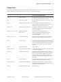
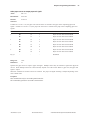
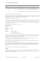
Comparisons
The following table details the list of commands whose behavior differs from the A793 and the A794 because of the
physical differences of a 6 dots/mm head (A793) versus an 8 dots/mm head (A794).
Command
Description
Difference between previous product
and new product Emulation Mode
15 n
Feed n Dot Rows
This command will move the paper on the receipt in n/
203 inch steps instead of n/152 inch steps.
16 n
Add n Extra Dot Rows
The dot rows will be measured in n/203 inches versus
n/152 inches.
1B 20 n
Set Right-Side Character Spacing This command sets the right side spacing to “n”
horizontal motion units. By default, these units are in
terms of 1/203 inches versus 1/152 inches.
1B 24 n1 n2
Set Absolute Starting Position
For graphics commands, the position is scaled to best
match A793. In text mode, the equivalent character
position is calculated.
1B 26 s c1 c2 n1 d1...nn dn]
Define User-Defined
Character Set
Since the dots on the A794 printhead are
smaller, user defined characters that were used
on the previous printers will appear smaller
on the A974 printer.
1B 2A m n1 n2 d1...dn
Select Bit Image Mode
In A793 Emulation Mode, graphics are scaled to best
match the size of the graphic in the A793 printer.
1B 33 n
Set Line Spacing
This command uses n in terms of n/360 inches. Since
the A793 had a fundamental step of 1/152 inch and the
A794 has a fundamental step of 1/203 inch, the actual
line spacing will not exactly match the requested
spacing.
1B 4A n
Print and Feed Paper
(Same as above)
1B 59 n1 n2 d1...dn
Select Double-Density Graphics
In A793 Emulation Mode, the printer scales the graphics
to provide the best match.
1B 5C n1 n2
Set Relative Print Position
The parameter to this command is in units of dots.
However, the command moves and aligns to character
positions. In A793 Emulation Mode, this command
calculates how many character positions to move
based on the A793 character width in dots (10) versus t
he A794 (13).
1B 61 n
Select Justification
This command does true dot resolution alignment for
centering versus character-aligned centering.
1D 2A n1 n2 d1...dn]
Define Downloaded Bit Image
In A793 Emulation Mode, this command scales the
incoming data to provide a best match to the size of
the image as it printed on A793.
1D 2F m
Print Downloaded Bit Image
(Same as above)
A794-D100 10/04
189-9200250 Rev. C
A794 Thermal Receipt Printer: Owner’s Guide
64
Chapter 6: Programming Information
Command descriptions
Printer function commands
The printer function commands control the following basic printer functions and are described in order of their
hexadecimal codes:
•
•
•
Resetting the printer
Cutting the paper
Opening the cash drawers
Clear printer
ASCII
Hexadecimal
Decimal
DLE
10
16
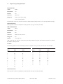
Clears the print line buffer without printing and sets the printer to the following condition:
•
Double-Wide command (0x12) is canceled
•
Line Spacing, Pitch, and User-Defined Character Sets are maintained at current selections (RAM is not
affected)
•
Single-Wide, Single-High, Non-Rotated, and Left-Aligned characters are set
•
Printer is restarted and error status is cleared in a fault condition
•
Printing position is set to column one
•
Knife is homed
Exceptions
In printers with the Parallel interface, this command also returns paper exhaust to the paper status line if an alternate
status has been requested. A DLE command followed by a 04 or 05 is interpreted as a “Real Time Command”. (See
Real Time Command.)
Related information
This command is recognized in A793 Emulation and A794 Native Mode, ignored in LEGACY Emulation.
Perform full knife cut
ASCII
Hexadecimal
Decimal
EM
19
25
ESC i
1B 69
27 105
Cuts the receipt.
There are two codes (Hex 19 or 1B 69) for this command and both perform the same function.
Exceptions
The full cut is replaced by a partial cut in the A793 emulation. ASCII EM, (0x19) is ignored in LEGACY Emulation.
A794 Thermal Receipt Printer: Owner’s Guide
189-9200250 Rev. C
A794-D100 10/04
Chapter 6: Programming Information
65
Perform partial knife cut
ASCII
Hexadecimal
Decimal
SUB
1A
26
ESC m
1B 6D
27 109
Partially cuts the receipt. The default setting leaves 5 mm. (0.20 inch) of paper on the left edge. (See Setting Partial
Cut Distance in Diagnostics.)
There are two codes (Hex 1A or 1B 6D) for this command and both codes perform the same function.
Formulas
The cut edge is 144 dot rows or 18 mm (0.71 inch) above the print station.
Exceptions
The command is valid only at the beginning of a line. ASCII SUB, (0x1A), is ignored in LEGACY Emulation. Line Feed
is executed first, if the buffer is not empty.
Generate tone
ASCII
Hexadecimal
Decimal
ESC BEL
1B 07
27 7
Generates an audible tone. Performed by the printer to signal certain conditions.
Related information
This command is recognized in A793 Emulation and A794 Native Mode, ignored in LEGACY Emulation.
Select peripheral device (for multi-drop)
ASCII
ESC = n
Hexadecimal
1B 3D n
Decimal
27 61 n
Value of n:
0 (bit 0), device not selected
1 (bit 0), device selected
Default:
1 (bit 0), device selected
Selects the device to which the host computer sends data.
Related information
Other bits of n (1-7) are undefined and ignored.
When the printer is disabled by this command, it ignores transmitted data until the printer is re-enabled by the same
command.
A794-D100 10/04
189-9200250 Rev. C
A794 Thermal Receipt Printer: Owner’s Guide
66
Chapter 6: Programming Information
Initialize Printer
ASCII
ESC @
Hexadecimal
1B 40
Decimal
27 64
Default:
Character Pitch:
Column Width:
Extra Dot Rows:
Character Set:
Printing Position:
15.6 CPI
44 characters
3
Code Page 437
Column One
Clears the print line buffer and resets the printer to the default settings for the startup configuration (refer to Default
settings below).
Single-Wide, Single-High, Non-Rotated, and Left-Aligned characters are set and User-defined characters or logo
graphics are cleared. (Flash Memory is not affected.) Tabs reset to default. Receipt selection state is selected.
Exceptions
In printers with the Parallel interface, this command also returns paper exhaust to the paper status line if an alternate
status has been requested.
A794 Thermal Receipt Printer: Owner’s Guide
189-9200250 Rev. C
A794-D100 10/04
Chapter 6: Programming Information
67
Select paper sensors to output paper end signals
ASCII
ESC c 3 n
Hexadecimal
1B 63 33 n
Decimal
27 99 51 n
Value of n:
If either bit 0 or bit 1 is on, the paper roll near-end sensor is selected as the paper sensor outputting paper-end
signals. If either bit 2 or bit 3 is on, the paper roll end sensor is selected as the paper sensor outputting paper-end
signals.
Bit
Position
Hex
Decimal
Function
0
Off
On
00
01
0
1
Paper roll near-end sensor disabled
Paper roll near-end sensor enabled
1
Off
On
00
02
0
2
Paper roll near-end sensor disabled
Paper roll near-end sensor enabled
2
Off
On
00
04
0
4
Paper roll near-end sensor disabled
Paper roll near-end sensor enabled
3
Off
On
00
08
0
8
Paper roll near-end sensor disabled
Paper roll near-end sensor enabled
4, 5, 6, 7
-
-
-
Undefined
Range of n:
1-255
Default of n:
12
Specifies the paper sensor to output a paper end signal. Multiple sensors may be selected to signal when paper has
run out. When multiple sensors have been selected, anytime one of the sensors detects a paper end, the paper end
signal is output.
When this command is executed a sensor is switched. The paper end signal switching is delayed depending on the
receive buffer state.
Exceptions
This command can only be used with a parallel interface.
The command is ignored if it used with a serial interface.
A794-D100 10/04
189-9200250 Rev. C
A794 Thermal Receipt Printer: Owner’s Guide
68
Chapter 6: Programming Information
Select sensors to stop printing
ASCII
ESC c 4 n
Hexadecimal
1B 63 34 n
Decimal
27 99 52 n
Value of n:
Sensor status
Sensor Status
Bit
Sensor
0
1
0
Receipt Paper Near-End
Disabled
Enabled
1
Receipt Paper Near-End
Disabled
Enabled
2-4
Undefined
6
Undefined
Bits 5 and 7 are not used.
Default:
0
Determines which sensor stops printing on the respective station. The command does not affect the paper out status
on the receipt station, which will automatically stop the printer when the paper is depleted.
Enable or disable panel button
ASCII
ESC c 5 n
Hexadecimal
1B 63 35 n
Decimal
27 99 53 n
Value of n:
0 = Enable
1 = Disable
Default:
0 (Enable)
Enables or disables the Paper Feed Button. If the last bit is 0, the Paper Feed Button is enabled. If the last bit is 1, the
Paper Feed Button is disabled.
Exceptions
Functions that require the Paper Feed Button (except for the Execute Macro [1D 5E] command) cannot be used when
it has been disabled with this command.
A794 Thermal Receipt Printer: Owner’s Guide
189-9200250 Rev. C
A794-D100 10/04
Chapter 6: Programming Information
Generate pulse to open cash drawer
ASCII
ESC p
n p1 p2
Hexadecimal
1B 70
n p1 p2
Decimal
27 112
n p1 p2
Value of n:
00, 48 (Decimal) = Drawer 1;
01, 49 (Decimal) = Drawer 2
Value of p1:
0-255
Value of p2:
0-255
Sends a pulse to open the cash drawer.
Formulas
The value for either p1 or p2 is the hexadecimal number multiplied by 2 msec to equal the total time.
•
On-time = p1 (Hex) x 2 msec
•
Off-time = p2 (Hex) x 2 msec
Related Information
The off-time is the delay before the printer performs the next operation. Refer to cash drawer specifications for
required on and off-time.
Select Cut Mode and Cut Paper
ASCII
GS V m
GS V m n
Hexadecimal
1D 56 m
1D 56 m n
Decimal
29 86 m
29 86 m n
Value of m:
Selects the mode as shown in the table.
Value of n:
Determines cutting position only if m is 65 or 66.
m
Feed and Cut Mode
0, 48
Full cut (no extra feed).
1, 49
Partial cut (no extra feed).
65
Feeds paper to cutting position + (n times vertical motion unit), and cuts the paper
completely.
66
Feeds paper to cutting position + (n times vertical motion unit), and performs a partial
cut.
Range of m:
0, 48; 1, 49
65, 66 (when used with n)
Range of n:
0 – 255
Default of m, n:
0
Selects a mode for cutting paper and cuts the paper. There are two formats for this command, one requiring one
parameter m, the other requiring two parameters m and n. The format is indicated by the parameter m.
Formulas
“n” times the vertical motion unit is used to determine the cutting position to which the paper is fed.
A794-D100 10/04
189-9200250 Rev. C
A794 Thermal Receipt Printer: Owner’s Guide
69
70
Chapter 6: Programming Information
Print Test Form
ASCII
Hexadecimal
Decimal
AX t
1F 74
31 116
Prints the current printer configuration settings on the receipt.
Disabled in Page Mode.
A794 Thermal Receipt Printer: Owner’s Guide
189-9200250 Rev. C
A794-D100 10/04
Chapter 6: Programming Information
Vertical positioning and print commands
The vertical positioning and print commands control the vertical print positions of characters on the receipt.
Print and feed one line
ASCII
LF
Hexadecimal
0A
Decimal
10
Prints one line from the buffer and feeds paper one line.
Carriage Return/Line Feed pair prints and feeds only one line.
Activate carriage return
ASCII
CR
Hexadecimal
0D
Decimal
13
Prints one line from the buffer and feeds paper one line. The printer can be set through the configuration menu to
ignore or use this command. Some applications expect the command to be ignored while others use it as print
command.
Related information
See Ignoring/Using the Carriage Return in Diagnostics for more information.
This command is recognized in A793 Emulation and A794 Native Mode, ignored in
LEGACY Emulation.
Carriage Return/Line Feed pair prints and feeds only one line.
Feed n print lines
ASCII
DC4 n
Hexadecimal
14 n
Decimal
20 n
Value of n:
The number of lines to feed at current line height setting.
Range of n:
0-255 in A794 Native Mode
0-127 in A793 Emulation
Feeds the paper n lines at the current line height without printing. Ignored on receipt if current line is not empty.
Related information
This is ignored in LEGACY Emulation and the parameter byte goes into the print buffer.
A794-D100 10/04
189-9200250 Rev. C
A794 Thermal Receipt Printer: Owner’s Guide
71
72
Chapter 6: Programming Information
Feed n dot rows
ASCII
NAK n
Hexadecimal
15 n
Decimal
21 n
Value of n:
n/203 inch
Range of n:
0-255 in A794 Native Mode
0-127 in A793 Emulation
Feeds the paper n dot rows (n/8 mm, n/203 inch), without printing. Receipt moves n rows if the print buffer is empty.
Related information
This is ignored in LEGACY Emulation and the parameter byte goes into the print buffer.
Add n extra dot rows
ASCII
SYN n
Hexadecimal
16 n
Decimal
22 n
Value of n:
Number of extra dot rows
Range of n:
0-16
Default:
3 extra dot rows
Adds n extra dot rows (n/8 mm, n/203 inch) to the character height to increase space between print lines or decrease
the number of lines per inch.
Formulas
The following table shows the relationship between the number of lines per inch and each extra dot row added:
Extra
Rows
Lines Per
Inch
Dot
Rows
Extra
Rows
Lines Per
Inch
Dot
Rows
0
8.5
24
9
6.1
33
1
8.1
25
10
3.0
34
2
7.8
26
11
5.8
35
3
7.5
27
12
5.6
36
4
7.2
28
13
5.5
37
5
7.0
29
14
5.3
38
6
6.8
30
15
5.2
39
7
6.5
31
16
5.1
40
8
6.3
32
Related information
This is ignored in LEGACY Emulation and the parameter byte goes into the print buffer.
A794 Thermal Receipt Printer: Owner’s Guide
189-9200250 Rev. C
A794-D100 10/04
Chapter 6: Programming Information
73
Print
ASCII
ETB
Hexadecimal
17
Decimal
23
Prints one line from the buffer and feeds paper one line. Executes LF on receipt.
Related information
This command is recognized in A793 Emulation and A794 Native Mode, ignored in
LEGACY Emulation.
Set line spacing to 1/6 inch
ASCII
ESC 2
Hexadecimal
1B 32
Decimal
27 50
Default:
3.33 mm (0.13 inch)
Sets the default line spacing to 4.25 mm (1/6 of an inch).
Set line spacing
ASCII
ESC 3 n
Hexadecimal
1B 33 n
Decimal
27 51 n
Value of n:
n/406 inch in A794 Native Mode
n/360 inch in A793 Emulation Mode
n/203 inch in LEGACY Emulation Mode
Range of n:
0-255
Default:
3.37 mm (0.13 inch)
Sets the line spacing to n/16 mm (n/406 inch).
The minimum line spacing is 8.5 lines per inch. The line spacing equals the character height when n is too small.
If the Set Horizontal and Vertical Minimum Motion Units command (1D 50) is used to change the horizontal and
vertical minimum motion unit, the parameters of this command (Set Line Spacing) will be interpreted accordingly.
Related information
For more information, see the description of the Set Horizontal and Vertical Minimum Motion Units command in this
document.
A794-D100 10/04
189-9200250 Rev. C
A794 Thermal Receipt Printer: Owner’s Guide
74
Chapter 6: Programming Information
Print and feed paper
ASCII
ESC J n
Hexadecimal
1B 4A n
Decimal
27 74 n
Value of n:
n/203 inch in A794 Native Mode and LEGACY Emulation Mode
n/360 inch in A793 Emulation Mode
Range of n:
0-255
Prints one line from the buffer and feeds the paper n/8 mm (n/203 inch). The line height equals the character height
when n is too small.
If the Set Horizontal and Vertical Minimum Motion Units command (1D 50) is used to change the horizontal and
vertical minimum motion units, the parameters of this command (Print and Feed Paper) will be interpreted accordingly.
Related information
For more information, see the description of the Set Horizontal and Vertical Minimum Motion Units command in this
document.
Print and feed n lines
ASCII
ESC d n
Hexadecimal
1B 64 n
Decimal
27 100 n
Range of n:
1-255 (0 is interpreted as 1)
Prints one line from the buffer and feeds paper n lines at the current line height.
Set horizontal and vertical minimum motion units
ASCII
GS P x y
Hexadecimal
1D 50 x y
Decimal
29 80 x y
Value of x:
Horizontal
Value of y:
Vertical
Range of x:
0 – 255
Range of y:
0 – 255
Default of x:
203
Default of y:
203
Sets the horizontal and vertical motion units to 1/x inch and 1/y inch respectively.
When x or y is set to 0, the default setting for that motion unit is used.
A794 Thermal Receipt Printer: Owner’s Guide
189-9200250 Rev. C
A794-D100 10/04
Chapter 6: Programming Information
75
Horizontal positioning commands
The horizontal positioning commands control the horizontal print positions of characters on the receipt.
The commands describe operation for 80 mm paper. If the printer supports 82.5 mm paper, the dot spacing is the same
but there are 640 printable dots rather 576 printable dots on the 80 mm paper.
Horizontal tab
ASCII
HT
Hexadecimal
09
Decimal
9
Moves the print position to the next tab position set by the Set Horizontal Tab Positions (1B 44 n1 n2 ... 00)
command. The print position is reset to column one after each line.
Tab treats the left margin as column one, therefore changes to the left margin will move the tab positions.
When no tabs are defined to the right of the current position, or if the next tab is past the right margin, Line Feed is
executed. HT has no effect in Page Mode.
Print initialization sets 32 tabs at column 9, 17, 25…
Set column
ASCII
ESC DC4 n
Hexadecimal
1B 14 n
Decimal
27 20 n
Value of n:
1-44= Standard pitch
1-56= Compressed pitch
Default of n:
1
Prints the first character of the next print line in column n. It must be sent for each line not printed at column one. The
value of n is set to one after each line.
Exceptions
This command cannot be used with Single- or Double-Density graphics.
Related information
This is ignored in LEGACY Emulation and the parameter byte goes into the print buffer.
A794-D100 10/04
189-9200250 Rev. C
A794 Thermal Receipt Printer: Owner’s Guide
76
Chapter 6: Programming Information
Set absolute starting position
ASCII
ESC $ nL nH
Hexadecimal
1B 24 nL nH
Decimal
27 36 nL nH
Value of n:
n=
nL =
nH =
Number of dots to be moved from the beginning of the line.
Remainder after dividing n by 256.
Integer after dividing n by 256.
The values for nL and nH are two bytes in low byte, high byte word orientation.
Sets the print starting position to the specified number of dots (up to the right margin) from the beginning of the line.
The print starting position is reset to the first column after each line.
Formulas
The example shows how to calculate 280 dots as the absolute starting position.
28 x 10 = 280 dots (beginning of column 29)
280/256 = 1, remainder of 24
nL = 24
nH =
1
Related information
If the Set Horizontal and Vertical Motion Units command (1D 50) is used to change the horizontal and vertical
minimum motion unit, the parameters of the Set Relative Print Position command will be interpreted accordingly. For
more information, see the description of the command Set Horizontal and Vertical Minimum Motion Units command
(1D 50) in this document.
Compatibility information (A794 receipt vs. A793 receipt)
There is a difference in the normal behavior of this command in A794 Emulation Mode as compared to the original
A793. The difference exists when the command is used to move to the left. The A793 processes the whole print string
prior to putting it in the buffer for the print head. This method of processing allows the A793 to backup in the print
string and replace characters and their associated attributes when a “Set Relative Print Position” command instructs
the printer to move the print position to the left.
In order to improve the speed of printing, the A794 moves the data into a buffer for the printhead when it receives it.
When the “Set Relative Print Position” command contains a move to the left, this causes the new data to overstrike
the previous data. This behavior can be used to an application’s advantage to provide the ability to create compound
characters on the receipt station.
This command also functions differently in the A793 Emulation when used in graphics:
n x 2 = Number of dots to be moved from the beginning of the line when this command is followed by a
graphics command.
A794 Thermal Receipt Printer: Owner’s Guide
189-9200250 Rev. C
A794-D100 10/04
Chapter 6: Programming Information
77
Set horizontal tab positions
ASCII
ESC D [n]…k NUL
Hexadecimal
1B 44 [n]…k 00
Decimal
27 68 [n]…k 0
Value of n:
Column number for tab minus one.
(n is always less than or equal to the current selected column width)
Value of k:
0-32
Default:
Every 8 characters from column. 1 (9, 17, 25, etc.) for normal print.
Sets up to 32 horizontal tab positions n columns from column one, but does not move the print position. See the
Horizontal Tab command (09).
The tab positions remain unchanged if the character widths are changed after the tabs are set. The command ends
with hexadecimal 00; hexadecimal 1B 44 00 clears all tabs.
Tabs assumed to be in strictly ascending order. A tab out of order terminates the command string as if it were 00, and
remaining tab values are taken as normal data.
Formulas
Set the tab positions in ascending order and put Hex 00 at the end.
Hex 1B 44 00 (number of tabs not specified) clears all tab positions.
Exceptions
The tabs cannot be set higher than the column width of the current pitch:
Standard pitch = 44 columns
Compressed pitch = 56 columns
A794-D100 10/04
189-9200250 Rev. C
A794 Thermal Receipt Printer: Owner’s Guide
78
Chapter 6: Programming Information
Set relative print position
ASCII
ESC \ n1 n2
Hexadecimal
1B 5C n1 n2
Decimal
27 92 n1 n2
Value of n:
To Move the Relative Starting Position Right of the Current Position:
n=
n1 =
n2 =
Number of dots to be moved right of the current position
Remainder after dividing n by 256
Integer after dividing n by 256
The values for n1 and n2 are two bytes in low byte, high byte word orientation.
To Move the Relative Starting Position Left of the Current Position:
n=
n1 =
n2 =
Number of dots to be moved left of the current position
Remainder after dividing (65,536-n) by 256
Integer after dividing (65,536-n) by 256
The values for n1 and n2 are two bytes in low byte, high byte word orientation.
Moves the print starting position the specified number of dots either right (up to the right margin) or left (up to the
left margin) of the current position. The print starting position is reset to the first column after each line.
Formulas
To move to the left:
Determine the value of n by multiplying the number of columns to move left of the current position by 10 (standard)
or 8 (compressed) pitch. The example shows how to set the relative position two columns in standard pitch (10 dots
per column) to the left of the current position.
2 x 10 = 20 dots (two columns to be moved left of the current position)
65,536-20 = 65516
65,516/256 = 255, remainder of 236
n1 = 236, n2 = 255
To move to the right:
Determine the value of n by multiplying the number of columns to move right of the current position by 10 (standard)
or 8 (compressed) pitch. The example shows how to set the relative position two columns in standard pitch (10 dots
per column) to the right of the current position.
2 x 10 = 20 dots (two columns to be moved left of the current position)
20/256 = 0, remainder of 20
n1 = 20, n2 = 0
Related information
If the Set Horizontal and Vertical Minimum Motion Units command (1D 50) is used to change the horizontal and
vertical minimum motion unit, the parameters of this command (Set Relative Print Position) will be interpreted
accordingly. For more information, see the description of the Set Horizontal and Vertical Minimum Motion Units
command (1D 50) in this document.
(continued next page)
A794 Thermal Receipt Printer: Owner’s Guide
189-9200250 Rev. C
A794-D100 10/04
Chapter 6: Programming Information
79
Compatibility information (A794 receipt vs. A793 receipt)
There is a difference in the normal behavior of this command in A794 Emulation Mode as compared to the original
A793. The difference exists when the command is used to move to the left. The A793 processes the whole print string
prior to putting it in the buffer for the print head. This method of processing allows the A793 to backup in the print
string and replace characters and their associated attributes when a “Set Relative Print Position” command instructs
the printer to move the print position to the left.
In order to improve the speed of printing, the A794 moves the data into a buffer for the printhead when it receives it.
When the “Set Relative Print Position” command contains a move to the left, this causes the new data to overstrike
the previous data. This behavior can be used to an application’s advantage to provide the ability to create compound
characters on the receipt station.
This command also functions differently in the A793 Emulation when used in graphics:
nx2=
Number of dots to be moved from the beginning of the line when this
command is followed by a graphic command.
Select justification
ASCII
ESC a n
Hexadecimal
1B 61 n
Decimal
27 97 n
Value of n:
0, 48 = Left aligned
1, 49 = Center aligned
2, 50 = Right aligned
Range of n:
0-2, 48-50
Default:
0 (Left aligned)
Specifies the alignment of characters, graphics, logos, and bar codes on the receipt station according to the above
table.
Related information
On the LEGACY, this command is valid only at the beginning of a line.
On the A793 this command accepts any n £ 255, using the low 2 bits:
00
01
10
11
A794-D100 10/04
left aligned
center
right aligned
center
189-9200250 Rev. C
A794 Thermal Receipt Printer: Owner’s Guide
80
Chapter 6: Programming Information
Set left margin
ASCII
GS L nL nH
Hexadecimal
1D 4C nL nH
Decimal
29 76 nL nH
Range of nL:
0-255
Range of nH:
0-255
Default:
576 dots (the maximum printable area)
Formulas
Sets the left margin of the printing area. The left margin is set to ((nH X 256) + nL) times horizontal motion unit)
inches. The horizontal motion units are set by the Set Horizontal and Vertical Minimum Motion Units command (1D
50), described in this manual.
The width of the printing area is set by the Set Printing Area Width command (1D 57), which follows this command.
See the Set Printing Area Width command in this document for a description of that command.
If the setting exceeds the printable area, the maximum value of the printable area is used. The maximum printable area
is 576 dots. See the illustration.
To set the left margin to one inch at the default horizontal motion unit of 1/203 inches, send the four-byte string:
GS L 203 0
Or, to set the left margin to two inches at the default horizontal motion unit of 1/203 units per inch, send the four-byte
string:
GS L 150 1
Where 2 inches = 406/203, and 406 = (1 X 256) + 150.
Exceptions:
The command is effective only at the beginning of a line. This Command is ignored if the line buffer is not empty, and
only effects the receipt interface.
A794 Thermal Receipt Printer: Owner’s Guide
189-9200250 Rev. C
A794-D100 10/04
Chapter 6: Programming Information
81
Set Printing Area Width
ASCII
GS W nL nH
Hexadecimal
1D 57 nL nH
Decimal
29 87 nL nH
Range of nL:
0-255
Range of nH:
0-255
Default:
576 dots (the maximum printable area)
Sets the width of the printing area. If the setting exceeds the printable area, the maximum value of the printable area is
used. The width of the printing area is set to ((nH X 256) + nL) times horizontal motion unit) inches. The horizontal
motion units are set by the Set Horizontal and Vertical Minimum Motion Units command (1D 50).
The width of the printing area follows the Set Left Margin command (1D 4C). See the Set Left Margin command
(10 4C …) earlier in this document for a description.
Formulas
To set the width of the printing area to one inch at the default horizontal motion unit of 1/203 inches, send the fourbyte string:
GS W 203 0
Or, to set the width of the printing area to two inches at the default horizontal motion unit of 1/203 units per inch,
send the four-byte string:
GS W 150 1
Where 2 inches = 406/203, and 406 = (1 X 256) + 150.
Exceptions
This command is effective only at the beginning of a line.
If the setting exceeds the printable area, the maximum value of the printable area is used. The maximum printable area
is 576 dots. See the illustration.
A794-D100 10/04
189-9200250 Rev. C
A794 Thermal Receipt Printer: Owner’s Guide
82
Chapter 6: Programming Information
Print characteristics commands
These commands control what the printed information looks like, selection of character sets, definition of customdefined characters, and setting of margins. The commands are described in order of their hexadecimal codes.
The commands describe operation for 80 mm paper. If the printer supports 82.5 mm paper, the dot spacing is the same
but there are 640 printable dots rather than 576 printable dots on 80 mm paper.
Select double-wide characters
ASCII
DC2
Hexadecimal
12
Decimal
18
Prints double-wide characters. The printer is reset to single-wide mode after a line has been printed or the Clear
Printer (0x10) command is received. Double-wide characters may be used in the same line with single-wide characters.
Exceptions
Double-wide characters may not be used in the same line with single or double-density graphics.
Related information
This command is ignored in LEGACY Emulation.
Select Single-Wide Characters
ASCII
DC3
Hexadecimal
13
Decimal
19
Prints single-wide characters. Single-wide characters may be used in the same line with double-wide characters.
Exceptions
Single-wide characters may not be used in the same line with single or double-density graphics.
Related information
This command is ignored in LEGACY Emulation.
A794 Thermal Receipt Printer: Owner’s Guide
189-9200250 Rev. C
A794-D100 10/04
Chapter 6: Programming Information
83
Select 90 degree counter-clockwise rotated print
ASCII
ESC DC2
Hexadecimal
1B 12
Decimal
27 18
Rotates characters 90 degrees counter-clockwise. The command remains in effect until the printer is reset or until a
Clear Printer (0x10), Select or Cancel Upside Down Print (1B 7B) or Cancel Rotated Print (1B 56) command is received.
Exceptions
This command is valid only at the beginning of a line.
Rotated print and non-rotated print characters cannot be used together in the same line.
Related Information
See “Summary of Rotated Printing” in this document.
This command is ignored in LEGACY Emulation.
Select pitch (column width)
ASCII
ESC SYN n
Hexadecimal
1B 16 n
Decimal
27 22 n
Value of n:
0 = Standard pitch
1 = Compressed pitch
Default:
0 (Standard pitch)
Selects the character pitch for a print line
Formulas
The following table provides the print characteristics for both pitches on the receipt station.
Pitch
Columns,
80 mm Paper
Columns,
82,5 mm Paper
CPI
Standard
44
49
15.6
Compressed
56
64
20.3
Related information
See Print Specifications for a description of both pitches.
This command and the Select Print Modes command (1B 21 n) affect pitch selection.
This is ignored in LEGACY Emulation and the parameter byte goes into the print buffer.
A794-D100 10/04
189-9200250 Rev. C
A794 Thermal Receipt Printer: Owner’s Guide
84
Chapter 6: Programming Information
Set right-side character spacing
ASCII
ESC SP n
Hexadecimal
1B 20 n
Decimal
27 32 n
Range of n:
0 – 32
Default:
0
Sets the right side character spacing to [n x horizontal or vertical motion units]. Values for this command are set
independently in standard and Page Mode.
The units of horizontal and vertical motion are specified by the Set Horizontal and Vertical Minimum Motion Units
(1D 50 …) command. Changes in the horizontal or vertical units do not affect the current right side character spacing.
When the horizontal or vertical motion unit is changed by the Set Horizontal and Vertical Minimum Motion Units (1D
50 …) command the value must be in even units and not less than the minimum amount of horizontal movement.
In Standard Mode the horizontal motion unit is used.
In Page Mode the horizontal or vertical motion unit differs and depends on the starting position of the printable area.
When the starting printing position is the upper left or lower right of the printable area (set by Select Print Direction
in Page Mode, 1B 54 n) the horizontal motion unit (x) is used. When the starting printing position is the upper right or
lower left of the printable area (set by Select Print Direction in Page Mode, 1B 54 n) the vertical motion unit (y) is
used.
Related information
This is ignored in LEGACY Emulation and the parameter byte goes into the print buffer. In the A793 Emulation, the
command and parameter byte are ignored.
A794 Thermal Receipt Printer: Owner’s Guide
189-9200250 Rev. C
A794-D100 10/04
Chapter 6: Programming Information
Select print mode
ASCII
ESC ! n
Hexadecimal
1B 21 n
Decimal
27 33 n
Value of n:
Pitch selection (standard, compressed, double high, or double wide.)
Value of n
Bit1
Function
Bit 0
Pitch
2
0
1
Standard Pitch
Compressed Pitch
(See chart below)
Bit 3
Emphasized Mode
Canceled
Set
Bit 4
Double High
Canceled
Set
Bit 5
Double Wide
Canceled
Set
Bit 7
Underlined Mode
Canceled
Set
1
Bits 1, 2 and 6 are not used.
2
Standard and compressed pitch cannot be used together in the same line.
Default:
0 (for bits 0, 3, 4, 5, 7)
This command and Select Pitch (Column Width) command (1B 16 n) affect Pitch Selection.
Pitch
Columns,
80 mm Paper
Columns,
82.4 mm Paper
CPI
Standard
44
49
15.6
Compressed
56
64
20.3
Selects the Print Mode: standard, compressed, emphasized, underlined, double high, or double wide.
Exceptions
Refer to the above table for exceptions.
Related information
See the Print Specifications Guide for a description of standard and compressed character pitches.
The bits in this command perform the same function as the stand-alone functions:
1B 16 n
1B 45 n
1B 47 n
12
13
1B 2D n
A794-D100 10/04
Select Pitch
Emphasized
Double Strike
Double Wide
Single Wide
Underline
189-9200250 Rev. C
A794 Thermal Receipt Printer: Owner’s Guide
85
86
Chapter 6: Programming Information
Select or cancel user-defined character set
ASCII
ESC % n
Hexadecimal
1B 25 n
Decimal
27 37 n
Value of n:
0 = Code Page 437
1 = User Defined (RAM)
2 = Code Page 850
Range of n:
0-2
Default:
0 (Code Page 437)
Selects the character set. When an undefined RAM character is selected, the current active ROM Code Page
character is used. See the Printing Specification Guide for the character sets.
Exception:
The character sets cannot be used together on the same line.
Related information
In LEGACY Emulation, the low order bit of n is used to select the User-Defined Character Set and the current active
ROM Code Page is not affected.
Define User-Defined Character Set
ASCII
ESC & s c1 c2 n1 d1 ... nn dn]
Hexadecimal
1B 26 s c1 c2 n1 d1 ... nn dn]
Decimal
27 38 s c1 c2 n1 d1 ... nn dn]
Values and Ranges:
s = 3, the number of bytes (vertically) in the character cell
c = the ASCII codes of the first (c1) and last (c2) characters respectively
c1 = Hex 20-FF (20 is always printed as a space)
c2 = Hex 20-FF (20 is always printed as a space)
To define only one character, use the same code for both c1 and c2
n = the number of dot columns for the nth character as specified by n1 ... nn
n = 1-16
d = the column data for the nth character as specified by d1 ... dn
The number of bytes for a character cell is s x n1.
The bytes are printed down and across each cell.
See the illustration on next page.
A794 Thermal Receipt Printer: Owner’s Guide
189-9200250 Rev. C
A794-D100 10/04
Chapter 6: Programming Information
Defines and enters downloaded characters into RAM. The command may be used to overwrite single characters.
User-defined characters are available until power is turned off or the Initialize Printer command (1B 40) is received.
Any invalid byte (s, c1, c2, n1) aborts the command.
Related information
See 1D 22 n (Select Memory Type) to save User-Defined Characters
Select or Cancel Underline Mode
ASCII
Hexadecimal
Decimal
ESC - n
1B 2D n
27 45 n
Value of n:
0, 48 = Cancel underline mode
1, 49 = Select underline mode
2, 50 = Select double thickness underline mode
Default:
0 (Cancel underline mode)
Turns underline mode on or off. Underlines cannot be printed for spaces set by the Horizontal Tab, Set Absolute
Start Position, or Set Relative Print Position commands.
This command and the Select Print Mode(s) command (1B 21) turn underline on and off in the same way.
Exceptions
This command is ignored if n is out of the specified range.
Related information
In A793 Emulation, this command is unrecognized and the parameter n is put into the print buffer.
A794-D100 10/04
189-9200250 Rev. C
A794 Thermal Receipt Printer: Owner’s Guide
87
88
Chapter 6: Programming Information
Copy character set from ROM to RAM
ASCII
ESC : 0 0 0
Hexadecimal
1B 3A 30 30 30
Decimal
27 58 0 0 0
Default:
current active ROM Code Page
Copies characters in the active ROM set to RAM. Use this command to re-initialize the User-Defined Character Set.
Code Page 437 is copied by default at initialization.
This command is ignored if current font is the user font.
Related information
To modify characters in one of the character set variations, such as Rotated Print, select one of the Rotated Print
commands, copy to RAM, then use the Define User-Defined Character Set command (1B 26).
Cancel user-defined character
ASCII
ESC ? n
Hexadecimal
1B 3F n
Decimal
27 63 n
Value of n:
specified character code
Range of n:
32-255
Cancels the pattern defined for the character code specified by n. After the user-defined character is canceled, the
corresponding pattern from current active ROM Code Page is printed.
Exceptions
This command is ignored if n is out of range or if the user-defined character is not defined.
A794 Thermal Receipt Printer: Owner’s Guide
189-9200250 Rev. C
A794-D100 10/04
Chapter 6: Programming Information
89
Select or Cancel Emphasized Mode
ASCII
ESC E n
Hexadecimal
1B 45 n
Decimal
27 69 n
Value of n:
0 (bit 0) not selected
1 (bit 0) selected
(When 0 and 1 are the Least Significant Bit, LSB)
Range of n:
0-255
Default:
0 (Off)
Starts or stops emphasized printing. The printer is reset to the standard Print Mode after a Clear Printer (0x10)
command is received.
Exceptions
Only the lowest bit of n is effective.
Emphasized printing cannot be used with bit-images or downloaded bit-images.
Related information
This command and the Select Print Mode(s) command (1B 21) function identically. They should have the same
setting when used together.
In A793 Emulation, this command is unrecognized and the parameter byte is put into the print buffer.
Select or Cancel Double Strike
ASCII
ESC G n
Hexadecimal
1B 47 n
Decimal
27 71 n
Value of n:
0 = Off
1 = On
(When 0 and 1 are the Least Significant Bit, LSB)
Default:
0 (Off)
Turns double strike mode on or off. Identical to Emphasized mode. The printer is reset to the standard Print Mode
after a Clear Printer (0x10) command is received.
Exceptions
Only the lowest bit of n is effective. The settings do not apply in Page Mode. However they can be set or cleared in
Page Mode.
Double-strike printing cannot be used with bit-images or downloaded bit-images.
Related information
This command and the Select Print Mode(s) command (1B 21) function identically. They should have the same
setting when used together.
In A793 Emulation, this command is unrecognized and the parameter byte is put into the print buffer.
A794-D100 10/04
189-9200250 Rev. C
A794 Thermal Receipt Printer: Owner’s Guide
90
Chapter 6: Programming Information
Select or cancel italic print
ASCII
ESC I n
Hexadecimal
1B 49 n
Decimal
27 73 n
Value of n:
0 = Off
1 = On
(When 0 and 1 are the Least Significant Bit, LSB)
Default:
0 (Off)
Turns Italic Print Mode on or off. The printer is reset to the standard Print Mode after a Clear Printer (0x10) command
is received.
Exceptions
Only the lowest bit of n is valid.
Related information
This command is recognized only in A794 Native Mode. In A973 and LEGACY Emulations, the parameter byte is put
into the buffer.
Select International Character Set and Select Character Code Table
ASCII
ESC R n
ESC t n
Hexadecimal
1B 52 n
1B 74 n
Decimal
27 82 n
27 116 n
Value of n:
A794 Native Mode
A793 Emulation
LEGACY Emulation
(1B 52 n only)
0 = Code Page 437
0 = Code Page 437
0 = U.S.A.
1 = Code Page 850
Not 0 = Code Page 850
1 = France
2 = Code Page 852
2 = Germany
3 = Code Page 860
3 =-U.K.
4 = Code Page 863
4 = Denmark I
5 = Code Page 865
5 = Sweden
6 = Code Page 858
6 = Italy
7 = Code Page 866
7 = Spain
8 = Code Page 1252
8 = Japan
9 = Norway
1
Default:
0 = Denmark II
0 (Code Page 437)
Selects the character set to be used. See Print Specifications for the character sets. There are two codes for this
command. Both codes perform the same function.
Related information
The LEGACY Emulation selection applies only to the command “Select International Character Set” (1B 52 n). T he
LEGACY Emulation generates the same as A794 Native Mode for the command “Select Character Code Table”
(1B 74 n).
A794 Thermal Receipt Printer: Owner’s Guide
189-9200250 Rev. C
A794-D100 10/04
Chapter 6: Programming Information
Select or cancel 90 degree clockwise rotated print
ASCII
ESC V n
Hexadecimal
1B 56 n
Decimal
27 86 n
Value of n:
0 = Cancel
1 = Set
Default:
0 (Cancel)
Rotates characters 90 degrees clockwise. The command remains in effect until the printer is reset or until a Clear
Printer (0x10) or Rotated Print (1B 12) command is received. See Summary of Rotated Printing in this document.
Select or Cancel Upside Down Print Mode
ASCII
ESC { n
Hexadecimal
1B 7B n
Decimal
27 123 n
Value of n:
0 = Cancel
1 = Set
Default:
0 (Cancel)
Prints upside-down characters. The command may be combined with Clockwise Rotated print (1B 56) or Counter
Clockwise Rotated print (1B 12). The character order is inverted in the buffer so text is readable. Only bit 0 is used.
Bits 1-7 are not used. See Summary of Rotated Printing in this document for more information.
Exceptions
The command is valid only at the beginning of a line.
It cannot be used with right side up characters on the same line.
Select character size
ASCII
GS ! n
Hexadecimal
1D 21 n
Decimal
29 33 n
Value of n:
1-8 = vertical number of times normal font
1-8 = horizontal number of times normal font
Range of n:
00-07, 10-17, ...70-77
Default of n:
11 hexadecimal
Selects the character height using bits 0 to 2 and selects the character width using bits 4 to 6, as follows:
A794-D100 10/04
189-9200250 Rev. C
A794 Thermal Receipt Printer: Owner’s Guide
91
92
Chapter 6: Programming Information
Character Width Selection
Hex
Decimal
Width
00
0
1 (normal)
10
16
2 (two times width)
20
32
3 (three times width)
30
48
4 (four times width)
40
64
5 (five times width)
50
80
6 (six times width)
60
96
7 (seven times width)
70
112
8 (eight times width)
Hex
Decimal
Height
00
0
1 (normal)
01
1
2 (two times height)
02
2
3 (three times height
03
3
4 (four times height)
04
4
5 (five times height)
05
5
6 (six times height)
06
6
7 (seven times height)
07
7
8 (eight times height)
Character Height Selection
This command is effective for all characters (except for HRI characters).
In Standard Mode, the vertical direction is the paper feed direction, and the horizontal direction is perpendicular to
the paper feed direction. However, when character orientation changes in 90 degree clockwise-rotation mode, the
relationship between vertical and horizontal directions is reversed.
In Page Mode, vertical and horizontal directions are based on the character orientation. When characters are enlarged
with different sizes on one line, all the characters on the line are aligned at the baseline.
The Select Print Mode (1B 21 n) command can also select or cancel double-width and double-height modes. However,
the setting of the last received command is effective.
Exception
If n is out of the defined range, this command is ignored.
Related information
In A793 Emulation, this command is discarded and not put into print buffer.
A794 Thermal Receipt Printer: Owner’s Guide
189-9200250 Rev. C
A794-D100 10/04
Chapter 6: Programming Information
93
Select or cancel white/black reverse print mode
ASCII
GS B n
Hexadecimal
1D 42 n
Decimal
29 66 n
Value of n:
0 = Off
1 = On
(When 0 and 1 are the Least Significant Bit, LSB)
Range of n:
0-255
Default:
0 (Off)
Turns on White/Black Reverse Print Mode. In White/Black Reverse Print Mode, print dots and non-print dots are
reversed, which means that white characters are printed on a black background. When the White/Black Reverse Print
Mode is selected it is also applied to character spacing which is set by Right-Side Character Spacing (1B 20).
This command can be used with built-in characters and user-defined characters, but does not affect the space
between lines.
White/Black Reverse Print Mode does not affect bit image, downloaded bit image, bar code, HRI characters, and
spacing skipped by Horizontal Tab (09), Set Absolute Starting Position (1B 24 …), and Set Relative Print Position (1B
5C).
White/Black Reverse Print Mode has a higher priority than Underline Mode. When Underline Mode is on and White/
Black Reverse Print Mode is selected, Underline Mode is disabled, but not canceled.
Exceptions
Only the lowest bit of n is valid.
Related information
In A793 Emulation, the command is unrecognized and the parameter byte is put into the print buffer.
Select or Cancel Smoothing Mode
ASCII
GS b n
Hexadecimal
1D 62 n
Decimal
29 98 n
This command is ignored.
A794-D100 10/04
189-9200250 Rev. C
A794 Thermal Receipt Printer: Owner’s Guide
94
Chapter 6: Programming Information
Select Superscript or Subscript Modes
ASCII
AX ENQ n
Hexadecimal
1F 05 n
Decimal
31 05 n
Value of n:
0 = Normal character size
1 = Select subscript size
2 = Select superscript size
Default:
0 (normal size)
Turns superscript or subscript modes on or off. This attribute may be combined with other characters size settings
commands (12, 13, 1B 21 n, 1D 21 n,…)
Exceptions
This command is ignored if n is out of the specified range.
Related information
In A793 Emulation, this command is unrecognized and the parameter byte is put into the print buffer.
Summary of Rotated Printing
The table shows the combinations of Set/Cancel Upside Down Print, Set/Cancel Rotated Print (clockwise), and
Rotated Print (counterclockwise).
Rotated clockwise and Rotated counterclockwise print commands are mutually exclusive: The setting of the last
received command is effective . Unintended consequences may result when Rotated clockwise is mixed with other
commands.
Rotated CW
(1B 56 n)
Rotated CCW
(1B 12)
Resulting Output
Canceled
Canceled
Cleared
A B C
Canceled
Set
X
C
B
A
Set
Canceled
X
A B C
Set
Set
X
C
X
X
Set
B
A
Upside Down
(1B 7B n)
A
B
C
The samples of the print show only the normal size characters. Double-wide and double-high characters are printed in
the same orientation. They may also be mixed on the same line.
Note: The following print modes cannot be mixed on the same lie:
•
Standard and compressed pitch
•
Vertical (normal) and rotated
•
Right-side up and upside down
•
Single high (normal) and double high
A794 Thermal Receipt Printer: Owner’s Guide
189-9200250 Rev. C
A794-D100 10/04
Chapter 6: Programming Information
Graphics commands
These commands are used to enter and print graphics data and are described in order of their hexadecimal codes.
These commands describe operation for 80 mm paper. If the printer supports 82.5 mm paper, the dot spacing is the
same but there are 640 printable dots rather than 576 printable dots on 80 mm paper.
Print raster graphics
ASCII
DC1 n1 ...nl
Hexadecimal
11 n1 ...n72
Decimal
17 n1 ...nl
Value of n:
n1…n72 = Data bytes
Range:
0-255
Prints one row of data. n1 . .. nl: bytes describing the line to print.
Exceptions
Raster graphics is not available in Page Mode.
Related information
This command is recognized only in A794 Native Mode.
In A793 and LEGACY Emulations, the data bytes are put into the print buffer.
A794-D100 10/04
189-9200250 Rev. C
A794 Thermal Receipt Printer: Owner’s Guide
95
96
Chapter 6: Programming Information
Download BMP logo
ASCII:
ESC (+*.BMP file)
Hexadecimal:
1B (+*.BMP file)
Decimal:
27 (+*.BMP file)
Value:
Maximum width = 576
Maximum height = 512
Enters a downloaded BMP logo into RAM or Flash.
The downloaded BMP logo can be printed by using the Print Downloaded Bit Image
(1D 2F m) command.
To downloaded BMP file to save it as a Logo, send the hexadecimal code 1B followed by the whole BMP file.
The printer decodes the BMP file header and will save the image data after checking important parameters, such as:
- Width,
- Height,
- Number of colors (only monochrome images are accepted)
Exceptions
BMP file images that are not monochrome are ignored.
Related information
Microsoft BMP bitmap file format.
This command is recognized only in A794 Native Mode.
In A793 and LEGACY Emulations, the BMP file bytes are put into the print buffer.
A794 Thermal Receipt Printer: Owner’s Guide
189-9200250 Rev. C
A794-D100 10/04
Chapter 6: Programming Information
97
Select Bit Image Mode
ASCII
ESC * m n1 n2 d1 ... dn
Hexadecimal
1B 2A m n1 n2 d1 ... dn
Decimal
27 42 m n1 n2 d1 ... dn
Value of m:
Value of m
ModeNo. of
Dots (Vertical)
No. of Dots (Horizontal)
No. of Dots/Line
0
8 Dot Single Density
8 (68 DPI)
0-288 (101 DPI)
8 x 288
1
8 Dot Double Density
8 (68 DPI)
0-576 (203 DPI)
8 x 576
32
24 Dot Single Density
24 (203 DPI)
0-288 (101 DPI)
24 x 288
33
24 Dot Double Density
24 (203 DPI)
0-576 (203 DPI)
24 x 576
Value of n:
Value of n (8-Dot Single Density Mode) Value of n (24-Dot Single Density Mode)
Value of d
n1 + (256 x n2)
Number of Bytes of Data
(Printed Down, Then Across)
3 x [n1 + (256 x n2)]
Sets the print resolution and enters one line of graphics data into the print buffer. Excess data is accepted but
ignored. Any print command is required to print the data, after which the printer returns to normal processing mode.
See the illustration for graphic representations of the bit image on the next page.
A794-D100 10/04
189-9200250 Rev. C
A794 Thermal Receipt Printer: Owner’s Guide
98
Chapter 6: Programming Information
Related information
A794 Thermal Receipt Printer: Owner’s Guide
189-9200250 Rev. C
A794-D100 10/04
Chapter 6: Programming Information
99
Print advanced raster graphics
ASCII
ESC . m n rL rH d1 … dn
Hexadecimal
1B 2E m n rL rH d1 … dn
Decimal
27 46 m n rL rH d1 … dn
Value of m:
horizontal offset from left margin = 8 x m dots
Value of n:
number of data bytes that compose the raster
Value of r:
number of times the raster has to be printed =256 x rH + rL
d1 … dn:
data bytes
Range:
0<= m <= 72
0<= n <= 72
0<= r <= 65535
0<= d1 … dn <= 255
Prints a horizontal raster of graphics data one or multiple times. Horizontal offset and number of data bytes are
variable and specified by parameters.
Exceptions
Advanced Raster graphics is not available in Page Mode
Select single-density graphics
ASCII
ESC K n1 n2 d1 ... dn
Hexadecimal
1B 4B n1 n2 d1 ... dn
Decimal
27 75 n1 n2 d1 ... dn
Value of n
Value of n (8-Dot Single Density Mode) Value of n (24-Dot Single Density Mode)
Value of d
n1 + (256 x n2)
Number of Bytes of Data
(Printed Down, Then Across)
3 x [n1 + (256 x n2)]
Enters one line of 8-dot single-density graphics into the print buffer. Any print command is required to print the line,
after which the printer returns to normal processing mode. Single-density mode allows 0-288 dot columns. The
number of bytes sent is represented by the formulas in the table.
Each bit corresponds to two horizontal dots. Compare to Set Bit Image Mode (1B 2A, m=0) earlier in this document.
Formulas
See the above table.
Related information
In LEGACY Emulation, this command is unrecognized and the parameters are put into the print buffer.
A794-D100 10/04
189-9200250 Rev. C
A794 Thermal Receipt Printer: Owner’s Guide
100
Chapter 6: Programming Information
Select double-density graphics
ASCII
ESC Y n1 n2 d1 ... dn
Hexadecimal
1B 59 n1 n2 d1 ... dn
Decimal
27 89 n1 n2 d1 ... dn
Value of n:
Value of n (8-Dot Single Density Mode) Value of n (24-Dot Single Density Mode)
Value of d
n1 + (256 x n2)
Number of Bytes of Data
(Printed Down, Then Across)
3 x [n1 + (256 x n2)]
Enters one line of 8-dot double-density graphics into the print buffer. Any print command is required to print the line,
after which the printer returns to normal processing mode. Double-density mode allows 0-576 dot columns. The
number of bytes sent is represented by the formulas in the table.
Each bit corresponds to one horizontal dot. Compare to Set Bit Image Mode (1B 2A, m=1) earlier in this document.
Formulas
See the above table.
Related information
In LEGACY Emulation, this command is unrecognized and the parameters are put into the print buffer.
A794 Thermal Receipt Printer: Owner’s Guide
189-9200250 Rev. C
A794-D100 10/04
Chapter 6: Programming Information
101
Select the current logo
ASCII
GS # n
Hexadecimal
1D 23 n
Decimal
29 35 n
Range of n:
0 – 255
Selects a logo to be defined or printed. The active logo n remains in use until this command is sent again with a
different logo n.
When this command precedes a logo definition, that definition is stored in Flash Memory as logo n. If there is already
a different definition in Flash Memory for logo n, the first is inactivated and the new definition is used. The inactive
definition is not erased from Flash and continues to take up space in Flash Memory.
When this command precedes a logo print command and n is different from the previously active logo selected, the
printer retrieves the logo definition for n from Flash Memory and prints it. If there is no definition for logo n, then no
logo is printed.
In the case of a previously existing application that expects only one possible logo, the printer will not receive the
Select Current Logo (1D 23 n) command. In this case, the printer assigns 0 as the active logo identifier. It
automatically stores any new logo definition in Flash Memory as logo 0, inactivating any previous logo 0 definition.
If the Flash Memory space available for logos fills up with inactive logo 0 definitions, the firmware erases the old
definitions at the next power cycle. This is the only case in which the printer erases Flash Memory without an
application command.
In the case of a new application using multiple logos, the Select Current Logo (1D 23 n) command is used. After that,
the printer no longer automatically erases the logo definition Flash Memory page when it fills with multiple
definitions. A new application using multiple logos, writing a user-defined character set into Flash Memory, or both,
is responsible for erasing the logo and user-defined character set Flash Memory page when the logo area is full or
before a new character set is defined.
Related information
This command is recognized only in A794 Native Mode.
In A793 and LEGACY Emulations, the parameters are put into the print buffer.
A794-D100 10/04
189-9200250 Rev. C
A794 Thermal Receipt Printer: Owner’s Guide
102
Chapter 6: Programming Information
Define Downloaded Bit Image
ASCII
GS * n1 n2 d1 ... dn]
Hexadecimal
1D 2A n1 n2 d1 ... dn]
Decimal
29 42 n1 n2 d1 ... dn]
Value of n:
Value of n1
Value of n2
Value of d
1-72 (8 x n1 = Number of
Horizontal Dot Columns)
1-64 (Number of Vertical Bytes)1
Bytes of Data (Printed Down, Then Across)
1
The number of bytes sent is represented by the following formula:
n = 8 x n1 x n2 (n1 x n2 must be less than or equal to 4608).
Enters a downloaded bit image (such as a logo) into RAM or Flash with the number of dots specified by n1 and n2.
The downloaded bit image is available until power is turned off, another bit image is defined, or Initialize Printer (1B
40) command is received.
See the illustration below for a graphic representation of the downloaded bit image.
A794 Thermal Receipt Printer: Owner’s Guide
189-9200250 Rev. C
A794-D100 10/04
Chapter 6: Programming Information
103
Print downloaded bit image
ASCII
GS / m
Hexadecimal
1D 2F m
Decimal
29 47 m
Value and Range of m:
Value of m
Print Mode
Vertical DPI
Horizontal DPI
0
Normal
203
203
1
Double Wide
203
101
2
Double High
101
203
3
Quadruple
101
101
Prints the downloaded bit image in RAM or Flash at a density specified by m. It is ignored if any data is in the print
buffer, if the downloaded bit image is undefined, or if the data defined exceeds one line.
See the illustration on the previous page for a representation of the bit image.
Convert 6 dots/mm bitmap to 8 dots/mm bitmap
ASCII
AX EOT n
Hexadecimal
1F 04 n
Decimal
31 04 n
Value:
0 = Off
1 = On
(When 0 and 1 are the LSB)
Default:
0 (Off)
Selects or cancels 6 dot/mm Emulation Mode.
When the 6 dot/mm emulation is selected, logos and graphics are expanded horizontally and vertically during
download to emulate their size on a 6 dot/mm printer. The horizontal positioning commands also emulate positioning
on a 6 dot/mm printer.
A794-D100 10/04
189-9200250 Rev. C
A794 Thermal Receipt Printer: Owner’s Guide
104
Chapter 6: Programming Information
Status commands
Status command introduction
The A794 has three methods of providing status to the application. These methods are through Batch Status
Commands, Real Time Status Commands, and Auto Status Back. An application may use one or more of these
methods to understand the current status of the printer. A brief description of each of these methods follows.
Batch status commands – These commands are sent to the printer and stored in the printer’s buffer. Once the printer
has processed all the previous commands these commands are processed and the proper status is returned to the
application. In the event a condition causes the printer to go BUSY, it stops processing commands from the printer
buffer. If a Batch Status Command remained in the buffer during this busy condition, it would not be processed. In
fact, no Batch Commands are processed while the printer is in this state.
Real-time commands – These commands are sent to the printer and are NOT stored in the printer’s buffer. Instead,
they are acted on immediately (regardless of the printer’s BUSY status) and their response (if any) is returned to the
application. This gives the application the ability to query the printer when it is in a busy state in order to correct
whatever fault has occurred.
Auto status back – This mechanism allows the application developer to program the printer to automatically respond
with a four byte status when certain conditions in the printer change.
Please see the subsequent sections for a more detailed description of these status commands. At the end of this
Status Commands section is a page entitled “Recognizing Data from the Printer”. This describes how to interpret
what command or setting (in the case of Auto Status Back) triggered a response from the printer.
Batch mode
For RS-232C printers, these commands enable the printer to communicate with the host computer following the
selected handshaking protocol, either DTR/DSR or XON/XOFF. They are stored in the printer’s data buffer as they
are received, and are handled by the firmware in the order in which they are received.
When a fault occurs, the printer will go busy at the RS-232C interface and not respond to any of the Batch Mode
Printer Status commands. If the fault causing the busy condition can be cleared, such as by loading paper, or letting
the thermal printhead cool down, the printer will resume processing the data in its receive buffer.
A794 Thermal Receipt Printer: Owner’s Guide
189-9200250 Rev. C
A794-D100 10/04
Chapter 6: Programming Information
105
Transmit peripheral device status (RS-232C printers only)
ASCII
ESC u 0
Hexadecimal
1B 75 0
Decimal
27 117 0
Value of returned byte:
Bit 0
Bit 1
1 = Drawer 1 Closed
1 = Drawer 2 Closed
0 = Drawer 1 Open
0 = Drawer 2 Open
Bits 2-7 are not used.
Transmits current status of the cash drawers. One byte is sent to the host computer. In DTR/DSR protocol, the
printer waits for DSR = SPACE. If a drawer is not connected, the status will indicate it is closed.
Exceptions
Unlike the A793, that had a dedicated connector and resultant dedicated status reporting for each cash drawer, the
A794 has a single connector that shares data reporting from either cash drawer. When either cash drawer is open, an
open status
is reported by the printer.
Related information
In LEGACY Emulation, this command is ignored.
Request Alternate Status (A793 Emulation Only)
ASCII
ESC u n
Hexadecimal
1B 75 n
Decimal
27 117 n
Value and Range of n:
Value of n
Function
Description
00
Drawer 1
High = Open
Low = Closed or Not Present
01
Drawer 2
High = Open
Low = Closed or Not Present
02
Paper Low (Not Implemented.
Interpreted as Paper Out.)
High = Paper Out
Low = Paper Present
03
Paper Out (Default)
High = Paper Out
Low = Paper Present
>03
Ignored, No Change
Printer Does Not Stay BUSY1
1
PAPER EXHAUST LINE is valid to indicate previously requested status.
This command allows the printer to inform the host when the data in the buffer has been processed. The PAPER
EXHAUST line shows the status for the cash drawer or receipt paper as shown in the table.
Status information is limited to what can be sent by the dedicated lines: BUSY, ACK, PAPER EXHAUST, and FAULT.
A794-D100 10/04
189-9200250 Rev. C
A794 Thermal Receipt Printer: Owner’s Guide
106
Chapter 6: Programming Information
Transmit paper sensor status
ASCII
ESC v
Hexadecimal
1B 76
Decimal
27 118
Values:
Status Byte (RS-232)
Bit
Function
0 Signifies
1 Signifies
0
Receipt Paper
Present
Low (only if paper low
sensor is enabled)
1
Receipt Cover
Closed
Open
2
Receipt Paper
Present
Out
3
Knife Position
Home Position
Not Home Position
4
Not Used
Fixed to Zero
Fixed to Zero
5
Temperature
In valid range
Too hot or too cold
6
Voltage
In valid range
Too high or too low
7
Not Used
Fixed to Zero
Fixed to Zero
Sends status data to the host computer. The printer sends one byte to the host computer when it is not busy or in a
fault condition. In DTS/DSR protocol, the printer waits for DSR = SPACE..
Related information
See Busy Line and Fault Conditions in the Real Time Commands section of this document for details about fault
condition reporting.
In LEGACY Emulation, this command is ignored.
A794 Thermal Receipt Printer: Owner’s Guide
189-9200250 Rev. C
A794-D100 10/04
Chapter 6: Programming Information
107
Transmit printer ID
ASCII
GS I n
Hexadecimal
1D 49 n
Decimal
29 73 n
Value of n:
1, 49 = Printer model ID
2, 50 = Type ID
3, 51 = ROM version ID
4, 52 = Logo Definition
Transmits the printer ID specified by n as follows:
n
Printer ID
Specification
ID (Hexadecimal)
1, 49
Printer model ID
A794
0x24
2, 50
Type ID
Installed options
Refer to next table
3, 51
ROM version ID
ROM version
0x00
4, 52
Logo Definition
Logo Definition
Refer to table below
n = 2 or 50: Type ID
Type ID (n = 2)
Bit
Off/On
Hex
Decimal
Function
0
Off
On
00
01
0
1
No two-byte character installed
Two-byte character code installed
1
Off
On
00
02
0
3
No knife installed
Knife installed
2
-
-
-
Undefined
3
-
-
-
Undefined
4
Off
00
0
Not used. Fixed to Off.
5
-
-
-
Undefined
6
-
-
-
Undefined
7
Off
00
0
Not used. Fixed to Off.
n = 4 or 52: Logo Definition
Bit
Off/On
Hex
Decimal
Function
0
Off
On
00
01
0
1
No logo downloaded (SRAM or Flash)
Logo downloaded (SRAM or Flash)
1-7
Off
00
0
Not used. Fixed to Off.
Transmits the printer ID specified by n. This command is a batch mode command; that is, the response is transmitted
after all prior data in the receive buffer has been processed. There may be a time lag between the printer receiving this
command and transmitting the response, depending on the receive buffer status.
When Auto Status Back (ASB) is enabled using the Enable/Disable Automatic Status Back command (1D 61), the
status transmitted by this command (Transmit Printer ID) and the ASB status must be differentiated according to the
information found in Recognizing Data from the Printer, (in the Real Time Commands section in this document).
A794-D100 10/04
189-9200250 Rev. C
A794 Thermal Receipt Printer: Owner’s Guide
108
Chapter 6: Programming Information
Transmit printer ID, remote diagnostics extension
ASCII
GS I @ n
Hexadecimal
1D 49 40 n
Decimal
29 73 64 n
Values of n:
Refer to table
The command performs the remote diagnostic function specified by n as described in the following table.
Value of n
ASCII
Hex
Dec
Remote Diagnostic Item
Function
Space
20
32
Serial #,
10 digit ASCII
Write to NVRAM
Example, send 14 bytes to printer:
GS I @ 0x20 1234567890
!
21
33
Serial #
Write to NVRAM, and print on receipt to verify
Example, send 14 bytes to printer:
GS I @ ! 1234567890
This will print on receipt: Serial # written:
1234567890
#
23
35
Serial #
Return Serial #, preceded by n to identify
Printer returns 12 bytes in above example:
#1234567890<CR>
$
24
36
Class/model #,
15 digit ASCII
Write to NVRAM
%
25
37
Class/model #
Write to NVRAM, and print on receipt to verify
‘
27
39
Class/model #
Return Class/model #, returns 17 bytes
+
2B
43
Boot firmware part #,
12 digit ASCII
Return Boot firmware part #, returns 14 bytes
/
2F
47
Boot firmware CRC,
4 digit ASCII
Return Boot firmware CRC, returns 6 bytes
3
33
51
Flash firmware part #,
12 digit ASCII
Return Flash firmware part #, returns 14 bytes
7
37
55
Flash firmware CRC,
4 digit ASCII
Return Flash firmware CRC, returns 6 bytes
Ç
80
128
Receipt lines tally,
8 digit ASCII numeric,
max 99,999,999
Write to NVRAM
Example, send 12 bytes to printer:
GS I @ Ç00010000
To set receipt lines tally to 10,000
ü
81
129
Receipt lines tally
Write to NVRAM, and print on receipt to verify
Example, send 12 bytes to printer:
GS I @ ü00010000
This will print on receipt:
Receipt tally written: 10,000
é
82
130
Receipt lines tally
Clear receipt lines tally to 0
A794 Thermal Receipt Printer: Owner’s Guide
189-9200250 Rev. C
A794-D100 10/04
Chapter 6: Programming Information
109
Value of n
ASCII
Hex
Dec
Remote Diagnostic Item
Function
â
83
131
Receipt lines tally
Return receipt lines tally, preceded by n to
identify.
Printer returns 10 bytes in above example:
â00010000<CR>
ä
84
132
Knife cut tally, 8 digit
ASCII numeric, max
99,999,999
Write to NVRAM
à
85
133
Knife cut tally
Write to NVRAM, and print on receipt to verify
å
86
134
Knife cut tally
Clear knife cut tally to 0
ç
87
135
Knife cut tally
Return knife cut tally, returns 10 bytes
É
90
144
Hours on tally, 8 digit
ASCII numeric, max
99,999,999
Write to NVRAM
æ
91
145
Hours on tally
Write to NVRAM, and print on receipt to verify
Æ
92
146
Hours on tally
Clear Hours on tally to 0
ô
93
147
Hours on tally
Return Hours on tally, returns 10 bytes
ù
97
151
Boot firmware version
Return Boot firmware version, returns 6 bytes
ú
A3
163
Flash firmware version
Return Flash firmware version, returns 6 bytes
ñ
A4
164
Flash cycles tally, 8 digit
ASCII numeric, max
99,999,999
Write to NVRAM
Ñ
A5
165
Flash cycles tally
Write to NVRAM, and print on receipt to verify
a
A6
166
Flash cycles tally
Clear Flash cycles cut tally to 0
o
A7
167
Flash cycles tally
Return Flash cycles cut tally, returns 10 bytes
¿
A8
168
Knife jams tally, 8 digit
ASCII numeric, max
99,999,999
Write to NVRAM
+
A9
169
Knife jams tally
Write to NVRAM, and print on receipt to verify
+
AA
170
Knife jams tally
Clear Knife jams tally to 0
½
AB
171
Knife jams tally
Return Knife jams tally, returns 10 bytes
¼
AC
172
Cover openings tally, 8
digit ASCII numeric, max
99,999,999
Write to NVRAM
¡
AD
173
Cover openings tally
Write to NVRAM, and print on receipt to verify
"
AE
174
Cover openings tally
Clear Cover openings tally to 0
A794-D100 10/04
189-9200250 Rev. C
A794 Thermal Receipt Printer: Owner’s Guide
110
Chapter 6: Programming Information
Value of n
ASCII
Hex
Dec
Remote Diagnostic Item
Function
"
AF
175
Cover openings tally
Return Cover openings tally, returns 10 bytes
¦
B2
178
Max Temperature tally
Reset Max Temperature Reached value
|
B3
179
Max Temperature tally
Return Max Temperature Reached since it was
Performs the remote diagnostic function specified by n.
Eighteen remote diagnostic items are defined: eight printer ID items and ten printer tally items. A group of four remote
diagnostic functions is assigned to each diagnostic item. Most of the diagnostic items are maintained in non-volatile
memory (NVRAM), but some are maintained in read-only memory (ROM).
The table that follows describes the variables.
The first item group in the table includes an example of data to send and to receive. Data sent from the host to write
to NVRAM must contain all digits required by the remote diagnostic item. All data must be ASCII. The printer returns
all ASCII data. It is preceded by the parameter n to identify the diagnostic item and is followed by a Carriage Return
(0D) to signify the end of the data.
Each returned message is defined as: n + data + <CR>
Transmit status
ASCII
GS r n
Hexadecimal
1D 72 n
Decimal
29 114 n
Value of n:
1, 49 = printer status
2, 50 = cash drawer status
4, 52 = Flash Memory User Sector status
Transmits the status specified by n. This is a batch mode command which transmits the response after all prior data
in the receive buffer has been processed. There may be a time lag between the printer receiving this command and
transmitting the response, depending on the receive buffer status.
When DTR/DSR RS-232C communications handshaking control is selected, the printer transmits the one byte
response only when the host signal DSR indicates it is ready to receive data.
When XON/XOFF RS-232C communications handshaking control is selected, the printer transmits the one byte
response regardless of the host signal DSR.
When Auto Status Back (ASB) is enabled using the Enable/Disable Automatic Status Back command (1D 61), the
status transmitted by this command (Transmit Status) and the ASB status must be differentiated according to the
information found in Recognizing Data from the Printer. This is found in the Real Time Commands section in this
document.
The status bytes to be transmitted are described in the following three tables.
Exceptions
Unlike the A793, that had a dedicated connector and resultant dedicated status reporting for each cash drawer, the
A794 has a single connector that shares data reporting from either cash drawer. When either cash drawer is open, an
open status is reported by the printer.
A794 Thermal Receipt Printer: Owner’s Guide
189-9200250 Rev. C
A794-D100 10/04
Chapter 6: Programming Information
111
Printer Status (n = 1 or n = 49)
Bit
Off/On
Hex
Decimal
Status for Transmit Status
0
Off
On
00
01
0
1
Paper present.
Paper exhausted.
1
Off
On
00
02
0
2
Cover closed.
Cover open.
2
Off
On
00
04
0
4
Paper present.
Paper exhausted.
3
-
-
-
Undefined.
4
Off
00
0
Not used. Fixed to off.
5
-
-
-
Undefined.
6
-
-
-
Undefined.
7
Off
00
0
Not used. Fixed to off.
Cash Drawer Status (n = 2 or n = 50)
Bit
Off/On
Hex
Decimal
Status for Transmit Status
0
Off
On
00
01
0
1
One or both cash drawers open.
Both cash drawers closed.
1
Off
On
00
02
0
2
One or both cash drawers open.
Both cash drawers closed.
2
-
-
-
Undefined
3
-
-
-
Undefined
4
Off
00
0
Not used. Fixed to off.
5
-
-
-
Undefined.
6
-
-
-
Undefined.
7
Off
00
0
Not used. Fixed to off.
Decimal
Status for Transmit Status
Flash Memory User Sector Status (n = 4 or n = 52)
Bit
Off/On
Hex
0
-
-
-
Undefined. Fixed to off.
1
-
-
-
Undefined. Fixed to off.
2
Off
00
0
Not Used. Fixed to off
3
Off
On
00
08
0
8
Flash Logo area adequate, definition stored
Flash Logo area not adequate
4
Off
00
0
Not used. Fixed to off.
5
Off
On
00
20
00
32
No thermal user-defined characters written.
Thermal User-defined characters written.
6
Off
00
0
Not used. Fixed to off.
7
-
-
-
Undefined.
Exceptions
When n is out of the specified range, the command is ignored.
A794-D100 10/04
189-9200250 Rev. C
A794 Thermal Receipt Printer: Owner’s Guide
112
Chapter 6: Programming Information
Exceptions
When n is out of the specified range, the command is ignored.
Send Printer Software Version
ASCII
AX V
Hexadecimal
1F 56
Decimal
31 86
The printer returns 8 bytes containing the boot and Flash software version. The first 4 bytes returned are an ASCII
string for the boot version. The second 4 bytes are an ASCII string for the Flash version. Example: For 1.234.56 (8
bytes), the boot version is 1.23 and the Flash version is 4.56.
A794 Thermal Receipt Printer: Owner’s Guide
189-9200250 Rev. C
A794-D100 10/04
Chapter 6: Programming Information
113
Real time commands
The Real Time commands provide an application interface to the printer even when the printer is not handling other
commands (RS-232C communication interface only):
•
Real Time Status Transmission: GS (Hex 1D) Sequence and DLE (Hex 10) Sequence
•
Real Time Request to Printer: GS (Hex 1D) Sequence and DLE (Hex 10) Sequence
•
Real Time Printer Status Transmission
The Batch Mode Printer Status commands are placed in the printer’s data buffer as they are received and handled by
the firmware in the order in which they were received. If the paper exhausts while printing data that was in the buffer
ahead of the status command, the printer goes busy at the RS-232C interface and suspends processing the data in
the buffer until paper is reloaded. This is true for all error conditions: knife home error, thermal printhead overheat,
etc. In addition, there is no way to restart the printer after a paper jam or other error, when using Batch Mode Status
commands.
The Real Time commands are implemented in two ways in order to overcome the limitations of Batch Mode Status
commands. Both implementations offer the same functionality; which one you choose depends on the current usage
of your application.
Preferred implementation
For a new application the GS (1D) sequences are recommended to avoid possible misinterpretation of a DLE (0x10)
sequence as a Clear Printer (0x10 0, ASCII DLE NUL) command.
An application using these GS (1D) sequences, does not need to distinguish for the printer between the new real time
commands and the Clear Printer command. This implementation is ideal for an existing A756 application that already
uses the Clear Printer command or for a new application being developed.
Alternate implementation
The alternate implementation uses the DLE (0x10) sequences as implemented on other printers. An application using
these DLE (0x10) sequences and the original A756 Clear Printer command (0x10) must distinguish for the printer
between the new real time commands and the Clear Printer command by adding a NUL (0x00) to the Clear Printer
command.
An application using these DLE (0x10) sequences must also send the second byte of the sequence within 100
milliseconds
A794-D100 10/04
189-9200250 Rev. C
A794 Thermal Receipt Printer: Owner’s Guide
114
Chapter 6: Programming Information
Rules for using real time commands
Three situations must be understood when using real time commands.
First, the printer executes the Real Time command upon receiving it and will transmit status regardless of the
condition of the DSR signal.
Second, the printer transmits status whenever it recognizes a Real Time Status Transmission command sequence,
even if that sequence happens to occur naturally within the data of another command, such as graphics data.
In this case the sequence will also be handled correctly as the graphics data it is intended to be when the graphics
command is executed from the buffer.
Third, care must be taken not to insert a Real Time command into the data sequence of another command that
consists of two or more bytes.
In this case the printer will use the real time command sequence bytes instead of the other command’s parameter
bytes when finally executing that other command from the buffer; the other command will NOT be executed correctly.
These three situations generally preclude use of standard DOS drivers for the serial communication ports when using
real time commands.
Moving data through the buffer
Applications should not let the buffer fill up with Real Time commands when the printer is busy at the RS-232C
interface. A busy condition at the RS-232C interface can be determined by bit 3 of the response to 1D 05, or 1D 04 1,
or 10 04 1. The reason for a particular busy condition can be determined by other responses to 1D 04 n or 10 04 n.
Although the printer responds to Real Time commands when it is busy, it will place them into the buffer behind any
other data there, and flush them out in the order in which they were received. When the printer is busy due simply to
buffer full (that is, it can’t print data as fast as it can receive it), then data continues to be processed out of the buffer
at approximately print speed and the Real Time commands will eventually get flushed out.
When the printer is busy due to an error condition, then data stops being processed of the buffer until the condition
clears one way or another. In either case, but more quickly in the case of an error condition, the buffer can fill with
Real Time commands.
When the DLE (0x10) sequences are being used, the last byte stored when the buffer fills up could be the DLE (0x10)
code, with no room for the subsequent EOT or ENQ. When this lone DLE (0x10) byte is finally processed out of the
buffer it will be interpreted as a Clear Printer command.
Similarly, when the GS (1D) sequences are being used, the last byte stored when the buffer fills up could be the GS
(1D) code, with no room for the subsequent EOT or ETX or ENQ. When this lone GS (1D) byte is finally processed
out of the buffer it will use the next byte, whatever it is, as the second byte in its GS (1D) sequence.
To guard against this situation, the application must determine the cause of a busy condition and take appropriate
action or pace the Real Time commands to avoid filling the buffer. There is a minimum of 256 bytes available in the
printer’s buffer when it goes busy.
A794 Thermal Receipt Printer: Owner’s Guide
189-9200250 Rev. C
A794-D100 10/04
Chapter 6: Programming Information
115
Busy line and fault conditions
If the printer is in error condition (cover is open, paper is exhausted…), the printer will still accept data, respond to
the batch mode status commands (1B 76 and 1B 75 0), handle the cash drawer commands, and not go busy until it
actually tries to execute a print command. Then it will stay busy and stop processing data out of the receive buffer
until the condition clears. It will respond to the Real Time commands as described below.
Real Time Status Transmission
GS Sequence
DLE Sequence
ASCII
Hexadecimal
Decimal
GS EOT n
1D 04 n
29 4 n
DLE EOT n
10 04 n
16 4 n
Value of n:
GS/DLE Sequence
1
2
3
4
= Transmit printer status
= Transmit RS-232C busy status
= Transmit error status
= Transmit receipt paper status
Transmits the selected one byte printer status specified by n in Real Time according to the following parameters. This
command includes two sequences: GS (1D) and DLE (0x10).
Exceptions
The command is ignored if n is out of range.
An application using DLE (0x10) sequence must send EOT within 100 milliseconds of DLE or the printer will
misinterpret the DLE and execute a Clear Printer command. Avoid this possibility by using the ID 04 n sequence,
which is handled exactly the same as 10 04 n.
Unlike the A793, that had a dedicated connector and resultant dedicated status reporting for each cash drawer, the
A794 has a single connector that shares data reporting from either cash drawer. When either cash drawer is open, an
open status
is reported by the printer.
Related information
1 = Transmit Printer Status
Bit
Status
Hex
Decimal
Function
0
Off
00
0
Fixed to Off.
1
On
02
2
Fixed to On.
2
Off
On
00
04
0
4
One or both cash drawers open.
Both cash drawers are closed.
3
Off
On
00
08
0
8
Not busy at the RS-232C interface.
Printer is busy at the RS-232C interface.
4
On
10
16
Fixed to On.
5
-
-
-
Undefined.
6
-
-
-
Undefined.
7
Off
00
0
Fixed to off.
A794-D100 10/04
189-9200250 Rev. C
A794 Thermal Receipt Printer: Owner’s Guide
116
Chapter 6: Programming Information
2 = Transmit RS-232C Busy Status
Bit
Status
Hex
Decimal
Function
0
Off
00
0
Fixed to Off.
1
On
02
2
Fixed to On.
2
Off
On
00
04
0
4
Cover closed.
Cover open.
3
Off
On
00
08
0
8
Paper feed button is not pressed.
Paper feed button is pressed.
4
On
10
16
Fixed to On.
5
Off
On
00
20
0
32
Printer not stopped due to paper condition.
Printing stopped due to paper condition.
6
Off
On
00
40
0
64
No error condition.
Error condition exists in the printer.
7
Off
00
0
Fixed to off.
3 = Transmit Error Status
Bit
Status
Hex
Decimal
Function
0
Off
00
0
Fixed to Off.
1
On
02
2
Fixed to On.
2
Off
00
0
Fixed to Off.
3
Off
On
00
08
0
8
No knife error.
Knife error occurred.
4
On
10
16
Fixed to On.
5
Off
On
00
20
0
32
No unrecoverable error.
Unrecoverable error occurred.
6
Off
00
0
On
40
64
Thermal printhead temp. and power supply
voltage are in range.
Thermal printhead temp. and power supply
voltage are out of range.
Off
00
0
7
A794 Thermal Receipt Printer: Owner’s Guide
189-9200250 Rev. C
Fixed to off.
A794-D100 10/04
Chapter 6: Programming Information
4 = Transmit Receipt Paper Status
Bit
Status
Hex
Decimal
Function
0
Off
00
0
Fixed to Off.
1
On
02
2
Fixed to On.
2
Off
On
00
04
0
4
Paper adequate.
Paper low. (if paper low sensor enabled)
3
Off
On
00
08
0
8
Paper adequate.
Paper low. (if paper low sensor enabled)
4
On
10
16
Fixed to On.
5
Off
On
00
20
0
32
Paper present.
paper exhausted.
6
Off
On
00
40
0
64
Paper present.
Paper exhausted.
7
Off
00
0
Fixed to off.
A794-D100 10/04
189-9200250 Rev. C
A794 Thermal Receipt Printer: Owner’s Guide
117
118
Chapter 6: Programming Information
Real time request to printer
GS Sequence
DLE Sequence
ASCII
GS ETX n
DLE ENQ n
Hexadecimal
1D 03 n
10 05 n
Decimal
29 3 n
16 5 n
Value of n:
1 = recover and restart
2 = recover and clear buffers
The printer responds to a request from the host specified by n. This command includes two sequences: GS and DLE.
The operations performed depend on the value of n, according to the following parameters.
n=1
Restarts printing from the beginning of the line where an error occurred, after recovering from the error. Print settings
that are normally preserved from line to line, such as character height and width, are still preserved with this
command. This sequence is ignored except when the printer is busy due to an error condition.
This command will attempt recovery from a knife error. Other errors associated with the receipt, such as paper out or
printhead overheating, can be recovered from only by clearing the specific condition, such as loading paper or letting
the printhead cool down.
n=2
Recovers from an error after clearing the receive and print buffers. Print settings that are normally preserved from line
to line, such as character height and width, are still preserved with this command. This sequence is ignored except
when the printer is busy due to an error condition.
The same error recovery possibilities exist as for n = 1.
Exceptions
The command is ignored if n is out of range.
An application using DLE (0x10) sequence must send ENQ within 100 milliseconds of DLE or the printer will
misinterpret the DLE and execute a Clear Printer command. Avoid this possibility by using the ID 03 n sequence, that
is handled exactly the same as 10 05 n.
A794 Thermal Receipt Printer: Owner’s Guide
189-9200250 Rev. C
A794-D100 10/04
Chapter 6: Programming Information
119
Real time printer status transmission
ASCII
GS ENQ
Hexadecimal
1D 05
Decimal
29 5
Transmits one byte status of the printer in real time.
Value of Byte:
Bit
Status
Hex
Decimal
Function
0
Off
On
00
01
0
1
Paper adequate.
Paper low (if paper low sensor enabled).
1
Off
On
00
02
0
2
Paper adequate.
Paper low (if paper low sensor enabled).
2
Off
On
00
04
0
4
Cover closed.
Cover open.
3
Off
On
00
08
0
8
Not busy at the RS-232C interface.
Printer is busy at the RS-232C interface.
4
Off
On
00
10
0
16
One or both cash drawers open.
Both cash drawers closed.
5
Off
00
0
Fixed to Off.
6
Off
On
00
40
0
64
No error condition.
Error condition exists in the printer.
7
On
80
128
Fixed to On.
Exceptions
Unlike the A793, that had a dedicated connector and resultant dedicated status reporting for each cash drawer, the
A794 has a single connector that shares data reporting from either cash drawer. When either cash drawer is open, an
open status is reported by the printer.
A794-D100 10/04
189-9200250 Rev. C
A794 Thermal Receipt Printer: Owner’s Guide
120
Chapter 6: Programming Information
Auto status back
Select or cancel automatic status back (ASB)
ASCII
GS a n
Hexadecimal
1D 61 n
Decimal
29 97 n
Value of n:
Status of ASB
Byte 1= printer information
Byte 2= error information
Byte 3= paper sensor information
Byte 4= paper sensor information
The bits of n are defined in the table.
Bit
Off/On
Hex
Decimal
Status for ASB
0
Off
On
00
01
0
1
Cash drawer status disabled.
Cash drawer status enabled.
1
Off
On
00
02
0
2
RS-232C Busy status disabled.
RS-232C Busy status enabled.
2
Off
On
00
04
0
4
Error status disabled.
Error status enabled.
3
Off
On
00
08
0
8
Receipt paper roll status disabled.
Receipt paper roll status enabled.
4
-
-
-
Undefined
5
-
-
-
Undefined.
6
-
-
-
Undefined
7
-
-
-
Undefined
Enables or disables Automatic Status Back (ASB) and specifies the status items. This command is a Batch Mode
command; that is, it is processed after all prior data in the receive buffer has been processed. There may be a time lag
between the printer receiving this command and changing the ASB response, depending on the receive buffer status.
If any of the status items listed above are selected, ASB is enabled and the printer automatically transmits 4 status
bytes whenever the selected status changes. If no status is selected, ASB is disabled. All four status bytes are
transmitted without checking DSR.
If the error status is enabled, a change in the following conditions will trigger the ASB:
•
Receipt Cover
•
Knife Error
•
Out-of-Range Printhead Temperature
•
Out-of-Range Voltage
•
Paper Exhaust
Default: 0 (ASB disabled)
A794 Thermal Receipt Printer: Owner’s Guide
189-9200250 Rev. C
A794-D100 10/04
Chapter 6: Programming Information
121
Exceptions
If n = 0, ASB is disabled.
Unlike the A793, that had a dedicated connector and resultant dedicated status reporting for each cash drawer, the
A794 has a single connector that shares data reporting from either cash drawer. When either cash drawer is open, an
open status is reported by the printer.
Related information
When the printer is disabled by the Select Peripheral Device command (1B 3D), this command (Enable/Disable
Automatic Status Back) is disabled but Automatic Status Back is not disabled.
When Auto Status Back (ASB) is enabled using this command, the status transmitted by other commands and the
ASB status be differentiated according to the information found in Recognizing Data from the Printer, (in the Real
Time Commands section in this document). The status bytes to be transmitted are described in the following four
tables.
In LEGACY Emulation, when the Handshaking Mode communication parameter is set to “RX Buffer Full”, the power
on ASB default is 02 (Busy Status enabled.) “RX Buffer Full” is the default Handshaking Mode in LEGACY
Emulation.
First Byte (Printer Information)
Bit
Off/On
Hex
Decimal
Status for ASB
0
Off
00
0
Not used. Fixed to off.
1
Off
00
0
Not used. Fixed to off.
2
Off
On
00
04
0
4
One or both cash drawers open.
Both cash drawers closed.
3
Off
On
00
08
0
8
Not Busy at the RS-232C interface.
Printer is Busy at the RS-232C interface.
4
On
10
16
Not used. Fixed to on.
5
Off
On
00
20
0
32
Cover closed.
Cover open.
6
Off
On
00
40
0
64
Paper Feed Button is not pressed.
Paper Feed Button is pressed.
7
Off
00
0
Not used. Fixed to off.
A794-D100 10/04
189-9200250 Rev. C
A794 Thermal Receipt Printer: Owner’s Guide
122
Chapter 6: Programming Information
Second byte (error information)
Bit
Off/On
Hex
Decimal
Status for ASB
0
-
-
-
Undefined
1
-
-
-
Undefined
2
-
-
-
Undefined
3
Off
On
00
08
0
8
No knife error.
Knife error occurred.
4
Off
00
0
Not used. Fixed to off.
5
Off
On
00
20
0
32
No unrecoverable error.
Unrecoverable error occurred.
6
Off
On
00
40
0
64
No recoverable error.
Recoverable Error : Cover open, paper out,
temperature or voltage error is out of range.
7
Off
00
0
Not used. Fixed to off.
Third byte (paper sensor information)
Bit
Off/On
Hex
Decimal
Status for ASB
0
Off
On
00
01
0
1
Paper present
Paper low (if paper low sensor enabled)
1
Off
On
00
02
0
2
Paper present
Paper low (if paper low sensor enabled)
2
Off
On
00
04
0
4
Paper present
Paper exhausted
3
Off
On
00
08
0
8
Paper present
Paper exhausted
4
Off
00
0
Not used. Fixed to off.
5
-
-
-
Undefined
6
-
-
-
Undefined
7
Off
00
0
Not used. Fixed to off.
Decimal
Status for ASB
Fourth byte (paper sensor information)
Bit
Off/On
Hex
0
-
-
-
Undefined
1
-
-
-
Undefined
2
-
-
-
Undefined
3
-
-
-
Undefined
4
Off
00
0
Not used. Fixed to off.
5
-
-
-
Undefined
6
-
-
-
Undefined
7
Off
00
0
Not used. Fixed to off.
A794 Thermal Receipt Printer: Owner’s Guide
189-9200250 Rev. C
A794-D100 10/04
Chapter 6: Programming Information
123
Recognizing Data from the Printer
An application sending various Real Time and non-Real Time commands to which the printer responds can determine
which command a response belongs to by the table below.
Responses to ESC u and ESC v are non-Real Time responses and will arrive in the order in which they were solicited.
Batch Mode Response
Response Recognized By:
1B 75 0
0 0 0 0 0 0 x x Binary
1B 76
0 0 0 0 0 x x x Binary
1D 49 n
0 x x 0 x x x x Binary
1D 72 n
0 x x 0 x x x x Binary
Real Time Response
Response Recognized By:
1D 04 n
0 x x 1 x x 1 0 Binary
10 04 n
0 x x 1 x x 1 0 Binary
1D 05
1 x x x x x x x Binary
XON
0 0 0 1 0 0 0 1 Binary
XOFF
0 0 0 1 0 0 1 1 Binary
Auto Status Back (ASB)
Response Recognized By:
ASB Byte 1
0 x x 1 x x 0 0 Binary
ASB Bytes 2-4
0 x x 0 x x x x Binary
A794-D100 10/04
189-9200250 Rev. C
A794 Thermal Receipt Printer: Owner’s Guide
124
Chapter 6: Programming Information
Bar code commands
These commands format and print bar codes and are described in order of their hexadecimal codes.
These commands describe operation for 80 mm paper. If the printer supports 82.5 mm paper, the dot spacing is the
same but there are 640 printable dots rather than 576 printable dots on 80 mm paper.
Select printing position of HRI characters
ASCII
GS H n
Hexadecimal
1D 48 n
Decimal
29 72 n
Value of n:
Printing position
0 = Not printed
1 = Above the bar code
2 = Below the bar code
3 = Both above and below the bar code
Default:
0 (Not printed)
Prints HRI (Human Readable Interface) characters above or below the bar code.
Select pitch of HRI characters
ASCII
GS f n
Hexadecimal
1D 66 n
Decimal
29 102 n
Value of n:
0 = Standard Pitch at 15 CPI
1 = Compressed Pitch at 20 CPI
Default:
0 (Standard Pitch at 15 CPI)
Selects standard and compressed font for printing Bar Code characters.
Select bar code height
ASCII
GS h n
Hexadecimal
1D 68 n
Decimal
29 104 n
Value of n:
Number of dots
Range of n:
1-255
Default:
216
Sets the bar code height to n dots or (n/8 mm , n/203 inch).
A794 Thermal Receipt Printer: Owner’s Guide
189-9200250 Rev. C
A794-D100 10/04
Chapter 6: Programming Information
125
Print bar code
First Variation
Second Variation
ASCII
GS k m d1…dk NUL
GS k m n d1…dn
Hexadecimal
1D 6B m d1…dk 00
1D 6B m n d1…dn
Decimal
29 107 m d1 dk 0
29 107 m n d1…dn
(0 = End of command)
Selects the bar code type and prints a bar code for the ASCII characters entered. If the width of the bar code exceeds
one line, the bar code is not printed.
There are two variations to this command. The first variation uses a NUL character to terminate the string; the second
uses a length byte at the beginning of the string to compensate for the Code 128 bar code, which can accept a NUL
character as part of the data. With the second variation the length of byte is specified at the beginning of the string.
Bar codes can be aligned left, center, or right using the Align Positions
command (1B 61).
The check digit is calculated for UPC and JAN (EAN) codes if it is not sent from the host computer. Six-character
zero-suppressed UPC-E tags are generated from full 11 or 12 characters sent from the host computer according to
standard UPC-E rules. Start/Stop characters are added for Code 39 if they are not included.
Rotated barcodes set with small modules (select bar code width command 1D 77 n , with n=1 or 2) and PDF 417
barcodes in any orientation are printed at low speed, for better readability.
Exceptions
The command is only valid at the beginning of a line.
Illegal data cancels the command.
Values:
First Variation: String terminated with NUL Character
m
Bar Code
d
n, Length
0
UPC-A
48- 57 (ASCII numerals)
Fixed Length: 11, 12
1
UPC-E
48- 57
Fixed Length: 11, 12
2
JAN13 (EAN)
48- 57
Fixed Length: 12, 13
3
JAN8 (EAN)
48- 57
Fixed Length: 7, 8
4
Code 39
48- 57,
65- 90 (ASCII alphabet),
32, 36, 37, 43, 45, 46, 47 (ASCII
special characters) d1 = dk = 42
(start/stop code is supplied by
printer if necessary)
Variable Length
5
Interleaved 2 of 5
48- 57
Variable Length
(Even Number)
6
Codabar
65- 68, start code 48- 57, 36, 43,
45, 46, 47, 58
10
PDF 417
32-255
A794-D100 10/04
189-9200250 Rev. C
Variable Length
Variable Length
A794 Thermal Receipt Printer: Owner’s Guide
126
Chapter 6: Programming Information
Second Variation Length of Byte Specified at Beginning of String
The value of m selects the bar code system as described in the table. When details present in the print buffer, the
printer processes the data following m as normal data.
The variable d indicates the character code to be encoded into the specified bar code system. See the table. If
character code d cannot be encoded, the printer prints the bar code data processed so far, and the following data is
treated as normal data.
m
Bar Code
d
n, Length
65
UPC-A
48- 57 (ASCII numerals)
Fixed Length: 11, 12
66
UPC-E
48- 57
Fixed Length: 11, 12
67
JAN13 (EAN)
48- 57
Fixed Length: 12, 13
68
JAN8 (EAN)
48- 57
Fixed Length: 7, 8
69
CODE39
48- 57, 65- 90 (ASCII alphabet),
32, 36, 37, 43, 45, 46, 47 (ASCII
special characters) d1 = dk = 42
(start/stop code is supplied by
printer if necessary)
Variable
70
Interleaved 2 of 5 (ITF)
48- 57
Variable (Even Number)
71
CODABAR (NW-7)
65- 68, start code 48- 57, 36, 43,
45, 46, 47, 58
Variable
72
Code 93
48- 57, 65- 90 (ASCII alphabet),
32, 36, 37, 43, 45, 46, 47 (ASCII
special characters) d1 = dn = 42
(start/stop code is supplied by
printer if necessary)
Variable
73
Code 128*
0-105
d1 = 103-105 (must be a Start code)
d2 = 0-102 (data bytes)
(Stop code is provided by the printer)
Variable
75
PDF 417
0-255
Variable Length
Exceptions:
Code 93 and PDF 417 are only available in A794 Native Mode.
Select bar code width
ASCII
GS w n
Hexadecimal
1D 77 n
Decimal
29 119 n
Value of n:
2, 3, 4, 5, 6
Default:
n=3
Sets the bar code width to n dots.
Formulas
n+1/8 mm (n+1/203 inch).
A794 Thermal Receipt Printer: Owner’s Guide
189-9200250 Rev. C
A794-D100 10/04
Chapter 6: Programming Information
127
Page mode commands
Page Mode is one of two modes that the A794 printer uses to operate. Standard Mode is typical of how most printers
operate by printing data as it is received and feeding paper as the various paper feed commands are received. Page
Mode is different in that it processes or prepares the data as a “page” in memory before it prints it. Think of this as a
virtual page. The page can be any area within certain parameters that you define. The page is printed using either the
FF (0C) or the ESC FF (1B 0C) command.
The Select Page Mode command (1B 4C) puts the printer into Page Mode. Any commands that are received are
interpreted as Page Mode commands. Several commands react differently when in Standard Mode and Page Mode.
The descriptions of these individual commands in this chapter indicate the differences in how they operate in the two
modes.
These commands describe the operation for 80 mm paper. If the printer supports 82.5 mm paper, the dot spacing is the
same but there are 640 printable dots rather than 576 printable dots on 80 mm paper.
Print and return to standard mode
ASCII
FF
Hexadecimal
0C
Decimal
12
When printing is completed, values for Select Print Direction in Page Mode (1B 54n) and Set Print Area in Page Mode
(1B 57 n1, n2, …n8) and the position for buffering character data are set. Buffered data is not deleted from the printer.
The processed data is printed and the printer returns to Standard Mode. The developed data is deleted after being
printed. For more information see Page Mode in this document.
Exceptions
This command is enabled only in Page Mode.
Cancel print data in page mode
ASCII
CAN
Hexadecimal
18
Decimal
24
Deletes all the data to be printed in the “page” area. Any data from the previously selected “page” area that is also
part of the current data to be printed is deleted.
Exceptions
This command is only used in Page Mode.
A794-D100 10/04
189-9200250 Rev. C
A794 Thermal Receipt Printer: Owner’s Guide
128
Chapter 6: Programming Information
Print data in page mode
ASCII
ESC FF
Hexadecimal
1B 0C
Decimal
27 12
Collectively prints all buffered data in the printing area.
After printing, the printer does not clear the buffered data and sets values for Select Print Direction in Page Mode (1B
54 n) and Set Print Area in Page Mode (1B 57 …), and sets the position for buffering character data.
Exceptions
This command is enabled only in Page Mode.
Select page mode
ASCII
ESC L
Hexadecimal
1B 4C
Decimal
27 76
Switches from Standard Mode to Page Mode. After printing has been completed either by the Print and Return to
Standard Mode (FF) command or Select Standard Mode (1B 53) the printer returns to Standard Mode. The developed
data is deleted after being printed. For more information see Page Mode in this document
This command sets the position where data is buffered to the position specified by Select Print Direction in Page
Mode (1B 54) within the printing area defined by Set Print Area in Page Mode (1B 57).
This command switches the settings for the following commands (which values can be set independently in Standard
Mode and Page Mode) to those for Page Mode.
•
Set Right-Side Character Spacing (1B 20)
•
Select 1/6-Inch Line Spacing (1B 32)
•
Set Line Spacing (1B 33)
It is possible only to set values for the following commands in Page Mode. These commands are not executed.
•
Select or Cancel 90 Degree Clockwise Rotation (1B 56)
•
Set Counter Clockwise Rotation (1B 12)
•
Select Justification (1B 61)
•
Select or Cancel Upside-Down Printing (1B 7B)
•
Set Left Margin (1D 4C)
•
Set Print Area Width (1D 57)
Exceptions
The command is enabled only when input at the beginning of a line
The command has no effect if Page Mode has previously been selected.
A794 Thermal Receipt Printer: Owner’s Guide
189-9200250 Rev. C
A794-D100 10/04
Chapter 6: Programming Information
129
Select standard mode
ASCII
ESC S
Hexadecimal
1B 53
Decimal
27 83
Switches from Page Mode to Standard Mode. In switching from Page Mode to Standard Mode, data buffered in Page
Mode are cleared, the printing area set by Set Print Area in Page Mode (1B 57) is initialized and the print position is
set to the beginning of the line.
This command switches the settings for the following commands (the values for these commands can be set
independently in Standard Mode and Page Mode) to those for Standard Mode:
•
Set Right-Side Character Spacing (1B 20)
•
Select 1/6 Inch Line Spacing (1B 32)
•
Set Line Spacing (1B 33)
Standard Mode is automatically selected when power is turned on, the printer is reset, or the Initialize Printer
command (1B 40) is used.
Exceptions
This command is effective only in Page Mode.
Select print direction in page mode
ASCII
ESC T n
Hexadecimal
1B 54 n
Decimal
27 84 n
Value of n:
Start position
0 = Upper left corner proceeding across page to the right (A)
1 = Lower left corner proceeding up the page (B)
2 = Lower right corner proceeding across page to the left
(upside down) (C)
3 = Upper right corner proceeding down page (D)
B
D
A
Default:
A794-D100 10/04
0
189-9200250 Rev. C
A794 Thermal Receipt Printer: Owner’s Guide
130
Chapter 6: Programming Information
Selects the printing direction and start position in Page Mode. See the illustration on previous page.
The command can be sent multiple times so that several different print areas, aligned in different print directions, can
be developed in the printer's page buffer before being printed using the Print Page Mode commands (0C or 1B 0C).
Exceptions
The command is valid only in Page Mode.
The command is ignored if the value of n is out of the specified range.
Set print area in page mode
ASCII
ESC W n1, n2 ...n8
Hexadecimal
1B 57 n1, n2 ...n8
Decimal
27 87 n1, n2 ...n8
Range of n:
0-255
Default:
n1-4 = 0
n5 = 64
n6 = 2
n7 = 64
n8 = 2
dx
(x0, y0)
dy
Print Area
(x0 + dx, y0 + dy)
Sets the position and size of the printing area in Page Mode.
The command can be sent multiple times so that several different print areas, aligned in different print directions, can
be developed in the printer's page buffer before being printed using the Print Page Mode commands (0C or 1B 0C).
Formulas
The starting position of the print area is the upper left of the area to be printed (x0, y0). The length of the area to be
printed in the y direction is set to dy inches. The length of the area to be printed in the x direction is set to dx inches.
Use the equations to determine the Value of x0, y0, dx, and dy.
•
x0 = [(n1 + n2 x 256) x (horizontal direction of the fundamental calculation pitch)]
•
y0 = [(n3 + n4 x 256) x (vertical direction of the fundamental calculation pitch)]
•
dx = [(n5 + n6 x 256) x (horizontal direction of the fundamental calculation pitch)]
•
dy = [(n7 + n8 x 256) x (vertical direction of the fundamental calculation pitch)]
Keep the following notes in mind for this command.
•
The fundamental calculation pitch depends on the vertical or horizontal direction.
•
The maximum printable area in the x direction is 576/203 inches.
•
The maximum printable area in the y direction is 576/203 inches.
See the illustration for a graphic representation of the printing area. For more information about the fundamental
calculation pitch, see the Set Horizontal and Vertical Motion Units command (1D 50).
Exceptions
The command is effective only in Page Mode.
A794 Thermal Receipt Printer: Owner’s Guide
189-9200250 Rev. C
A794-D100 10/04
Chapter 6: Programming Information
131
Set absolute vertical print position in page mode
ASCII
GS $ nL nH
Hexadecimal
1D 24 nL nH
Decimal
29 36 nL nH
Sets the absolute vertical print starting position for buffer character data in Page Mode. The absolute print position is
set to [(nL + nH X 256) x (vertical or horizontal motion unit)] inches.
The vertical or horizontal motion unit for the paper roll is used and the horizontal starting buffer position does not
move.
The reference starting position is set by Select Print Direction in Page Mode (1B 54). This sets the absolute position
in the vertical direction when the starting position is set to the upper left or lower right; and sets the absolute
position in the horizontal when the starting position is set to the upper right or lower left. The horizontal and vertical
motion unit are specified by the Set Horizontal and Vertical Minimum Motion Units (1D 50) command.
The Set Horizontal and Vertical Minimum Motion Units (1D 50) command can be used to change the horizontal and
vertical motion unit. However, the value cannot be less than the minimum horizontal movement amount, and it must
be in even units of the minimum horizontal movement amount.
Formulas
[(nL + nH X 256) x (vertical or horizontal motion unit)] inches.
Exceptions
This command is effective only in Page Mode.
If the [(nL + nH X 256) x (vertical or horizontal motion unit)] exceeds the specified printing area, this command is
ignored.
A794-D100 10/04
189-9200250 Rev. C
A794 Thermal Receipt Printer: Owner’s Guide
132
Chapter 6: Programming Information
Set relative vertical print position in page mode
ASCII
GS \ nL nH
Hexadecimal
1D 5C nL nH
Decimal
29 92 nL nH
Value:
The value for the horizontal and vertical movement cannot be less than the minimum horizontal movement amount,
and must be in even units of the minimum horizontal movement amount.
Sets the relative vertical print starting position from the current position. This command can also change the
horizontal and vertical motion unit. The unit of horizontal and vertical motion is specified by this command.
This command functions as follows, depending on the print starting position set by Select Print Direction in Page
Mode (1B 54):
1. When the starting position is set to the upper left or lower left of the printing area, the vertical motion
unit (y) is used.
2. When the starting position is set to the upper right or lower left of the printing area, the horizontal motion
unit (x) is used.
Formulas
The distance from the current position is set to [(nL + nH x 256) x vertical or horizontal motion unit] inches. The
amount of movement is calculated only for the paper roll.
When pitch n is specified to the movement downward:
nL + nH x 256 = n
When pitch n is specified to the movement upward (the negative direction), use the complement of 65536.
When pitch n is specified to the movement upward:
nL + nH x 256 – 65536 – N
Exceptions
This command is used only in Page Mode, otherwise it is ignored.
Any setting that exceeds the specified printing area is ignored.
A794 Thermal Receipt Printer: Owner’s Guide
189-9200250 Rev. C
A794-D100 10/04
Chapter 6: Programming Information
133
Macro commands
These commands are used to select and perform a user-defined sequence of printer operations.
Select or cancel macro definition
ASCII
GS :
Hexadecimal
1D 3A
Decimal
29 58
Starts or ends macro definition. Macro definition begins when this command is received during normal operation and
ends when this command is received during macro definition. The macro definition is cleared, during definition of the
macro when the Execute Macro (1D 5E) command is received.
Normal printing occurs while the macro is defined. When the power is turned on the macro is not defined.
The defined contents of the macro are not cleared by the Initialize Printer (1B 40), thus, the Initialize Printer (1B 40)
command may be used as part of the macro definition.
If the printer receives a second Select or Cancel Macro Definition (1D 3A) command immediately after previously
receiving a Select or Cancel Macro Definition (1D 3A) the printer remains in the macro undefined state.
Formulas
The contents of the macro can be defined up to 2048 bytes.
Exceptions
If the macro definition exceeds 2048 bytes, excess data is not stored.
A794-D100 10/04
189-9200250 Rev. C
A794 Thermal Receipt Printer: Owner’s Guide
134
Chapter 6: Programming Information
Execute macro
ASCII
GS ^ r t m
Hexadecimal
1D 5E r t m
Decimal
29 94 r t m
Value of r:
The number of times to execute the macro.
Value of t:
The waiting time for executing the macro.
Executes a macro. After waiting for a specified period the printer waits for the Paper Feed Button to be pressed. After
the button is pressed, the printer executes the macro once. The printer repeats this operation the number of specified
times.
When the macro is executed by pressing the Paper Feed Button (m = 1), paper cannot be fed by using the Paper Feed
Button.
Formulas
The waiting time is t x 100 ms for every macro execution.
“m” specifies macro executing mode when the LSB (Least significant bit) m = 0
The macro executes r times continuously at the interval specified by t when the LSB (Least significant bit) of m = 1.
Exceptions
If this command is received while a macro is being defined, the macro definition is aborted and the definition is
cleared.
If the macro is not defined or if r is 0, nothing is executed.
A794 Thermal Receipt Printer: Owner’s Guide
189-9200250 Rev. C
A794-D100 10/04
Chapter 6: Programming Information
135
User data storage commands
Write to user data storage
ASCII
ESC ‘ m a0 a1 a2 d1 ... dm
Hexadecimal
1B 27 m a0 a1 a2 d1 ... dm
Decimal
27 39 m a0 a1 a2 d1 ... dm
Value of m:
0 – 255
Writes m bytes of data to the User Data Storage Flash Page at the address specified. The printer waits for m bytes of
data following the 3-byte address, addr.
If any of the memory locations addressed by this command are not currently erased, the command is not executed.
Read from user data storage
ASCII
ESC 4 m a0 a1 a2
Hexadecimal
1B 34 m a0 a1 a2
Decimal
27 52 m a0 a1 a2
Value of m:
0 – 255
Reads m bytes of data from the User Data Storage Flash Page at the address specified.
Read from non-volatile memory
ASCII
ESC j k
Hexadecimal
1B 6A k
Decimal
27 106 k
Range of k:
20 – 63 (decimal)
Reads a two-byte word from location k in the history EEROM. The printer returns the word at the next available
opportunity.
Related information:
This is ignored in LEGACY Emulation and the parameter byte goes into the print buffer.
Write to non-volatile memory (NVRAM)
ASCI
ESC s
n1 n2 k
Hexadecimal
1B 73
n1 n2 k
Decimal
27 115
n1 n2 k
Value of n1:
1st Byte
Value of n2 :
2nd Byte
Range of k :
20 - 63 (decimal locations)
Writes the two-byte word, n1 n2, to location k in history EEROM.
Related information:
This is ignored in LEGACY Emulation and the parameter bytes go into the print buffer.
A794-D100 10/04
189-9200250 Rev. C
A794 Thermal Receipt Printer: Owner’s Guide
136
Chapter 6: Programming Information
Select memory type (SRAM/Flash) where to save logos or user-defined fonts
ASCII
GS “ n
Hexadecimal
1D 22 n
Decimal
29 34 n
Value of n:
48 - 51
n = 48 (ASCII n = 0)
Loads active logo to RAM only. This is used to print a special logo but not have it take up Flash Memory. A logo
defined following this command is not preserved over a power cycle.
n = 49 (ASCII n = 1)
Loads active logo to Flash Memory. This is the default condition for logo Flash storage. A logo defined following
this command is stored in Flash Memory.
n = 50 (ASCII n = 2)
Loads user-defined characters to RAM only. This is the default condition for user-defined character storage. Any
user-defined characters defined following this command are not preserved over a power cycle.
n = 51 (ASCII n = 3)
Loads user-defined characters to Flash Memory. An application must use this command to store user-defined
characters in Flash Memory. Any user-defined characters defined following this command are stored in Flash
Memory. A user-defined character cannot be redefined in Flash Memory. The Flash Memory page must be erased by
an application before redefining user-defined characters. For more information, see the Erase User Flash Sector (1D 40
n) command.
Specifies whether to load the logos or user-defined characters to Flash Memory or to RAM (volatile memory). The
selection remains in effect until it is changed via this command or until the power cycles.
Related information:
This command is recognized in A794 Native Mode. In A793 and LEGACY Emulations, parameter bytes go into the
print buffer.
A794 Thermal Receipt Printer: Owner’s Guide
189-9200250 Rev. C
A794-D100 10/04
Chapter 6: Programming Information
137
Flash memory user sectors allocation
ASCII
GS “ U n1 n
Hexadecimal
1D 22 55 n1 n2
Decimal
29 34 85 n1 n2
Default Value of n1:
1 (see below)
Default Value of n2:
1 (see below)
n1 is the number of 64k sectors used for logos and user-defined characters.
n2 is the number of 64k sectors used for user data storage.
n1 + n2 <= 2 (512K)
n1 + n2 <= 10 (1M)
n1 + n2 <= 18 (2M)
If n1 + n2 is greater than the maximum number of sectors available, the command is ignored.
Issuing this command with parameters different from current parameters will erase all sectors.
Erase user flash sector
ASCII
GS @ n
Hexadecimal
1D 40 n
Decimal
29 64 n
Value of n:
49 - 50
n = 49 (ASCII n = 1)
This command erases all 64K Flash Memory sectors allocated to user-defined character and logos storage. Those
sectors should be erased in two situations: when the logo definition area is full and an application is attempting to
define new logos, and when an application wants to replace one user-defined character set with another. In both
cases, all logos and character set definitions are erased and must be redefined.
n = 50 (ASCII n = 2)
This command erases all sectors available for user data storage.
Erases a page of Flash Memory and sends a carriage return when the operation is complete.
Related information
See command “Flash Memory User Sectors Allocation” (1D 22 55 n1 n2).
Important: While erasing Flash Memory, the printer disables all interrupts, including communications. To provide
feedback to the application, the printer responds to the application when the erase is complete. After sending the
Erase User Flash Sector (1D 40 n) command, an application should wait for the response from the printer before
sending data. Otherwise, data will be lost. If an application is unable to receive data, it should wait a minimum of five
seconds after sending the Erase User Flash Sector (1D 40 n) command before sending data.
A794-D100 10/04
189-9200250 Rev. C
A794 Thermal Receipt Printer: Owner’s Guide
138
Chapter 6: Programming Information
Flash Download Commands
These commands are used to load firmware into the printer.
The commands are listed in numerical order according to their hexadecimal codes. Each command is described and
the hexadecimal, decimal, and ASCII codes are listed.
There are three ways to enter the Download Mode.
1. Powering the printer up with DIP Switch 1 down.
2. While the printer is running normally, send the command, “Switch to Flash Download Mode (1B 5B 7D)”
to leave normal operation and enter the Download Mode.
3. If the Flash if found corrupted during Level 0 diagnostics the Download Mode is automatically entered
after the printer has reset.
The printer never goes directly from the Download Mode to normal printer operation. To return to normal printer
operation either the operator must turn the power off and then on to reboot or the application must send a command
to cancel Download Mode and reboot. DIP Switch 1 must in UP position during reboot to return to normal printer
operation.
When each Flash download command is received, the printer returns either ACK or NAK to the host computer when
each command is received:
•
ACK (hexadecimal 06)
Sent when the printer has received a host transmission and has completed the request successfully.
•
NAK (hexadecimal 15)
Sent when a request is unsuccessful.
Communicates to the printer information downloaded from applications. Data is downloaded to Flash memory to
query the state of the firmware, calculate the firmware CRC and other functions.
Switch to flash download mode
ASCII
ESC [ }
Hexadecimal
1B 5B 7D
Decimal
27 91 125
Puts the printer in Flash Download Mode in preparation to receive commands controlling the downloading of objects
into Flash Memory. When this command is received, the printer leaves normal operation and can no longer print
transactions until the Reboot the Printer command (1D FF) is received or the printer is rebooted.
This command does not affect the current communication parameters. Once the printer is in Flash Download Mode,
this command is no longer available.
Related information
See Entering Flash Download Mode elsewhere in this book to put the printer in Flash Download Mode using the
Configuration Menu.
A794 Thermal Receipt Printer: Owner’s Guide
189-9200250 Rev. C
A794-D100 10/04
Chapter 6: Programming Information
139
Return boot sector firmware part number
ASCII
GS NULL
Hexadecimal
1D 00
Decimal
29 0
Returns ACK (Hex 06) + 12 bytes ASCII string describing the Flash Memory Boot sector Firmware part number. Ex :
189-1234567A
Exceptions
Available only in Download Mode.
Return segment number status of flash memory
ASCII
GS SOH
Hexadecimal
1D 01
Decimal
29 1
Returns the size of the Flash used. There may be 4, 8, or 16 sectors (64K each) in Flash Memory. This command
assures that the firmware to be downloaded is the appropriate size for Flash Memory. The value returned is the
maximum sector number that can be accepted by the Select Sector to Download (1D 02 nn) command.
Exceptions
Available only in Download Mode.
Select Flash Memory Sector to Download
ASCII
GS STX nn
Hexadecimal
1D 02 nn
Decimal
29 2 nn
Value of n:
the Flash sector to which the next download operation applies
Range of n:
0
Selects the Flash sector (nn) for which the next download operation applies. The values of the possible sector are
restricted, depending upon the Flash part type. The printer transmits an ACK if the sector number is acceptable or an
NAK if the sector number is not acceptable. Sector numbers start at 0.
Exceptions
Available only in Download Mode.
Get firmware CRC
ASCII
GS ACK
Hexadecimal
1D 06
Decimal
29 6
Causes the printer to calculate the CRC for the currently selected sector and transmits the result. This is performed
normally after downloading a sector to verify that the downloaded firmware is correct. The printer also calculates the
CRC for each sector during power up and halts the program if any sector is erroneous.
The printer transmits ACK if the calculated CRC is correct for the selected sector; NAK if the CRC is incorrect or if no
sector is selected.
A794-D100 10/04
189-9200250 Rev. C
A794 Thermal Receipt Printer: Owner’s Guide
140
Chapter 6: Programming Information
Return microprocessor CRC
ASCII
GS BEL
Hexadecimal
1D 07
Decimal
29 7
Returns the CRC calculated over the boot sector code space.
Formulas
ACK <low byte> <high byte>
Erase all flash contents except boot sector
ASCII
GS SO
Hexadecimal
1D 0E
Decimal
29 14
Causes the entire Flash Memory to be erased.
The printer returns ACK if the command is successful; NAK if it is unsuccessful.
Exceptions
Available only in Download Mode.
Return main program flash CRC
ASCII
GS SI
Hexadecimal
1D 0F
Decimal
29 15
Returns the CRC calculated over the Flash firmware code space. The format of the response is ACK <low byte>
<high byte>.
Erase Selected Flash Sector
ASCII
GS DLE n
Hexadecimal
1D 10 n
Decimal
29 16 n
Value and Range of n:
0-7 =
0-15 =
0-31 =
512k bytes Flash
1M bytes Flash
2M bytes Flash
Erases the previously selected sector. The printer transmits ACK when the sector has been erased. If the previous
sector is not successfully erased, or if no sector was selected, the printer transmits NAK.
Exceptions
Available only in Download Mode.
A794 Thermal Receipt Printer: Owner’s Guide
189-9200250 Rev. C
A794-D100 10/04
Chapter 6: Programming Information
141
Download to active flash sector
ASCII
GS DC1 aL aH cL cH d1… dn
Hexadecimal
1D 11 aL aH cL cH d1… dn
Decimal
29 17 aL aH cL cH d1… dn
Value of aL:
low byte of the address
Value of aH:
high byte of the address
Value of cL:
low byte of the count
Value of cH:
high byte of the count
Value of d:
data bytes, 0-255
Value of n (for number of data bytes)
Range of Address (aL aH)
((cH * 256) + cL)
0000-FFFF (hexadecimal)
Range of Count (cL cH)
0001-FFFF (hexadecimal)
Range: Addresses run from 0 to 64K.
Contains a start address (aH x 256 + aL) and count (cH x 256 + cL) of binary bytes to load into the selected sector,
followed by that many bytes. The start address is relative to the start of the sector. Addresses run from 0 to 64K.
The printer may return one of several responses. ACK means that the data was written correctly and the host should
transmit the next block. NAK means that, for some reason, the data was not written correctly. This could mean that
communications failed or that the write to Flash failed. The alternatives seem to be to retry the block or halt loading
and assume a hardware failure.
Related information
Available only in Download Mode.
Reset firmware
ASCII
GS (SPACE)
Hexadecimal
1D FF
Decimal
29 255
Reboots the printer.
A794-D100 10/04
189-9200250 Rev. C
A794 Thermal Receipt Printer: Owner’s Guide
A794 Thermal Receipt Printer: Owner’s Guide
189-9200250 Rev. C
A794-D100 10/04