1
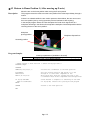
ROBOT
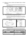
Vertical articulated
V SERIES
*
H SERIES
*
Cartesian coordinate
Horizontal articulated
XYC SERIES
Integrated compact type
XR SERIES
STARTUP HANDBOOK
Copyright © DENSO WAVE INCORPORATED, 2007-2010
All rights reserved. No part of this publication may be reproduced in any form or by any means without
permission in writing from the publisher.
Specifications are subject to change without prior notice.
All products and company names mentioned are trademarks or registered trademarks of their respective
holders.
Preface
Thank you for purchasing this high-speed, high-accuracy assembly robot.
Before operating your robot, read this manual carefully to safely get the maximum benefit from your robot
in your assembling operations.
Important
To ensure operator safety, be sure to read the precautions and instructions in "SAFETY PRECAUTIONS."
i
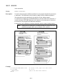
How the documentation set is organized
The documentation set consists of the following books. If you are unfamiliar with this robot and option(s),
please read all books and understand them fully before operating your robot and option(s).
GENERAL INFORMATION ABOUT ROBOT
Provides the packing list of the robot and outlines of the robot system, robot unit, and robot
controller.
INSTALLATION & MAINTENANCE GUIDE
Provides instructions for installing the robot components and customizing your robot, and
maintenance & inspection procedures.
STARTUP HANDBOOK - this book Introduces you to the DENSO robot system and guides you through connecting the robot unit
and controller with each other, running the robot with the teach pendant, and making and
verifying a program. This manual is a comprehensive guide to starting up your robot system.
SETTING-UP MANUAL
Describes how to set up or teach your robot with the teach pendant or mini-pendant.
For the panel designer functions, refer to the Panel Designer User's Manual (SUPPLEMENT).
WINCAPSIII GUIDE
Provides instructions on how to use the programming support tool WINCAPSIII which runs on
the PC connected to the robot controller for developing and managing programs.
PROGRAMMER'S MANUAL I, Program Design and Commands
Describes the PAC programming language, program development, and command
specifications in PAC. This manual consists of two parts; Part 1 provides the basic
programming knowledge, and Part 2, details of individual commands.
PROGRAMMER'S MANUAL II, PAC Library
Describes the program libraries that come with WINCAPSIII as standard.
RC7M CONTROLLER MANUAL
Provides the specifications, installation and maintenance of the RC7M controller. It also
describes interfacing with external devices, system- and user-input/output signals, and I/O
circuits.
ERROR CODE TABLES
List error codes that will appear on the teach pendant or mini-pendant if an error occurs in the
robot system. These tables also provide detailed description and recovery ways.
OPTIONS MANUAL
Describes the specifications, installation, and use of optional devices.
For the extension board "conveyer tracking board," refer to the OPTIONS MANUAL
(SUPPLEMENT).
ii
How this book is organized
This book is just one part of the documentation set. This book consists of SAFETY PRECAUTIONS and
chapters one through five.
SAFETY PRECAUTIONS
Defines safety terms, safety related symbols and provides precautions that should be observed. Be sure
to read this section before operating your robot.
Comprehensive Guidance Flow for STARTUP MANUAL
Part 1 Preparation for Installation (Chapters 1 through 5)
This part provides information on preparation for installation--robot system, RC7M controller, interfacing,
cabling, and wiring of dedicated signals.
Part 2 Robot Running (Chapters 6 through 8)
This part describes the coordinate systems, handling of the teach pendant, and teaching.
Part 3 Simple Programming (Chapters 9 through 11)
This part describes programming basics and provides instructions for creating programs with the teach
pendant or WINCAPSIII, using practice exercises.
Part 4 Program Verification (Chapters 12 through 15)
This part describes program verification procedures--simulation with WINCAPSIII and operational check
with the teach pendant and from external equipment. It also provides instructions for monitoring I/O
signals and variables.
Part 5 Advanced Usage (Chapters 16 through 20)
This part provides optimization of use conditions, frequently used program commands, and other
information for advanced usage.
Appendices
Appendix 1
Appendix 2
Appendix 3
Appendix 4
Appendix 5
Sample Answers to Practice Exercises
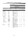
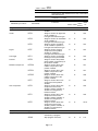
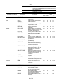
Commands Listed According to Functions
Menu Tree of Commands on Teach Pendant
Program Samples
Glossary
iii
SAFETY PRECAUTIONS
SAFETY PRECAUTIONS
Be sure to observe all of the following safety precautions.
Strict observance of these warning and caution indications are a MUST for preventing accidents, which
could result in bodily injury and substantial property damage. Make sure you fully understand all
definitions of these terms and related symbols given below, before you proceed to the text itself.
WARNING
Alerts you to those conditions, which could result
in serious bodily injury or death if the instructions
are not followed correctly.
CAUTION
Alerts you to those conditions, which could result
in minor bodily injury or substantial property
damage if the instructions are not followed
correctly.
Terminology and Definitions
Maximum space: Refers to the space which can be swept by the moving parts of the robot as defined by
the manufacturer, plus the space which can be swept by the end-effector and the workpiece. (Quoted
from the ISO 10218-1:2006.)
Restricted space: Refers to the portion of the maximum space restricted by limiting devices (i.e.,
mechanical stops) that establish limits which will not be exceeded. (Quoted from the ISO 10218-1:2006.)
Motion space: Refers to the portion of the restricted space to which a robot is restricted by software
motion limits. The maximum distance that the robot, end-effector, and workpiece can travel after the
software motion limits are set defines the boundaries of the motion space of the robot. (The "motion
space" is DENSO WAVE-proprietary terminology.)
Operating space: Refers to the portion of the restricted space that is actually used while performing all
motions commanded by the task program. (Quoted from the ISO 10218-1:2006.)
Task program: Refers to a set of instructions for motion and auxiliary functions that define the specific
intended task of the robot system. (Quoted from the ISO 10218-1:2006.)
1. Introduction
This section provides safety precautions to be observed for the
robot system.
The installation shall be made by qualified personal and should
confirm to all national and local codes.
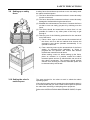
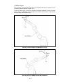
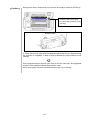
2. Warning Labels
The robot unit and controller have warning labels. These labels
alert the user to the danger of the areas on which they are
pasted. Be sure to observe the instructions printed on those
labels.
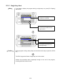
Warning label
Instructions printed on the label
Risk of injury.
Never enter the restricted space.
Label (1)
<Except HM>
For UL-Listed robot units only
Risk of injury.
This label alerts the user that pressing
the brake release switch could drop the
arm.
(Example: Location of labels)
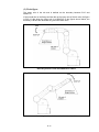
<HM>
Label (2)
Risk of electrical shock.
Never open the controller cover when
the power is on.
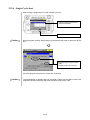
Label (3)
Never touch the inside of the controller
for at least 3 minutes even after turning
the power off and disconnecting the
power cable.
Risk of injury.
Label (4)
Be sure to perform lockout/tagout
before starting servicing.
Turning the power ON when a person is
inside the safety fence may move the
arm, causing injuries.
SAFETY PRECAUTIONS
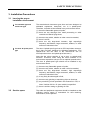
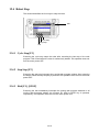
3. Installation Precautions
3.1 Insuring the proper
installation environment
For standard type and
cleanroom type
The standard and cleanroom types have not been designed to
withstand explosions, dust-proof, nor is it splash-proof.
Therefore, it should not be installed in any environment where:
(1) there are flammable gases or liquids,
(2) there are any shavings from metal processing or other
conductive material flying about,
(3) there are any acidic, alkaline or other corrosive material,
(4) there is a mist,
(5) there are any large-sized inverters, high output/high
frequency transmitters, large contactors, welders, or other
sources of electrical noise.
For dust- & splash-proof
type
The dust- & splash-proof type has an IP54-equivalent structure,
but it has not been designed to withstand explosions. (The
HM/HS-G-W and the wrist of the VM/VS-G-W are an
IP65-equivalent dust- and splash-proof structure.)
Note that the robot controller is not a dust- or splash-proof
structure. Therefore, when using the robot controller in an
environment exposed to mist, put it in an optional protective box.
The dust- & splash-proof type should not be installed in any
environment where:
(1) there are any flammable gases or liquids,
(2) there are any acidic, alkaline or other corrosive material,
(3) there are any large-sized inverters, high output/high
frequency transmitters, large contactors, welders, or other
sources of electrical noise,
(4) it may likely be submerged in fluid,
(5) there are any grinding or machining chips or shavings,
(6) any machining oil not specified in this manual is in use, or
Note: Yushiron Oil No. 4C (non-soluble) is specified.
(7) there is sulfuric cutting or grinding oil mist.
3.2 Service space
The robot and peripheral equipment should be installed so that
sufficient service space is maintained for safe teaching,
maintenance, and inspection.
3.3 Control devices
outside the robot's
restricted space
The robot controller, teach pendant and mini-pendant should be
installed outside the robot's restricted space and in a place
where you can observe all of the robot’s movements and operate
the robot easily.
3.4 Positioning of gauges
Pressure gauges, oil pressure gauges and other gauges should
be installed in an easy-to-check location.
3.5 Protection of electrical
wiring and
hydraulic/pneumatic
piping
If there is any possibility of the electrical wiring or
hydraulic/pneumatic piping being damaged, protect them with a
cover or similar item.
3.6 Grounding resistance
The protective grounding resistance of the robot power supply
should not be more than 100Ω.
3.7 Positioning of
emergency stop
switches
Emergency stop switches should be provided in a position where
they can be reached easily should it be necessary to stop the
robot immediately.
(1) The emergency stop switches should be red.
(2) Emergency stop switches should be designed so that they
will not be released after pressed, automatically or
mistakenly by any other person.
(3) Emergency stop switches should be separate from the
power switch.
3.8 Positioning of
operating status
indicators
Operating status indicators should be positioned in such a way
where workers can easily see whether the robot is on a
temporary halt or on an emergency or abnormal stop.
Note: The UL-Listed robot units have motor ON lamps on their
robot arms.
SAFETY PRECAUTIONS
3.9 Setting-up a safety
fence
A safety fence should be set up so that no one can easily enter
the robot's restricted space.
(1) The fence should be constructed so that it cannot be easily
moved or removed.
(2) The fence should be constructed so that it cannot be easily
damaged or deformed through external force.
(3) Establish the exit/entrance to the fence. Construct the fence
so that no one can easily get past it by climbing over the
fence.
(4) The fence should be constructed to ensure that it is not
possible for hands or any other parts of the body to get
through it.
(5) Take any one of the following protections for the entrance/
exit of the fence:
1) Place a door, rope or chain across the entrance/exit of
the fence, and fit it with an interlock that ensures the
emergency stop device operates automatically if it is
opened or removed.
2) Post a warning notice at the entrance/exit of the fence
stating "In operation--Entry forbidden" or "Work in
progress--Do not operate" and ensure that workers
follow these instructions at all times.
When making a test run, before setting up the fence,
place an overseer in a position outside the robot’s
restricted space and one in which he/she can see all of
the robot’s movements. The overseer should prevent
workers from entering the robot's restricted space and
be devoted solely to that task.
3.10 Setting the robot's
motion space
The area required for the robot to work is called the robot's
operating space.
If the robot’s motion space is greater than the operating space, it
is recommended that you set a smaller motion space to prevent
the robot from interfering or disrupting other equipment.
Refer to the INSTALLATION & MAINTENANCE GUIDE, Chapter
2.
3.11 No robot modification
allowed
Never modify the robot unit, robot controller, teach pendant or
other devices.
3.12 Cleaning of tools
If your robot uses welding guns, paint spray nozzles, or other
end-effectors requiring cleaning, it is recommended that the
cleaning process be carried out automatically.
3.13 Lighting
Sufficient illumination should be assured for safe robot
operation.
3.14 Protection from objects
thrown by the
end-effector
If there is any risk of workers being injured in the event that the
object being held by the end-effector is dropped or thrown by the
end-effector, consider the size, weight, temperature and
chemical nature of the object and take appropriate safeguards to
ensure safety.
3.15 Affixing the warning
label
Place the warning label packaged
with the robot on the exit/entrance
of the safety fence or in a position
where it is easy to see.
3.16 Posting the moving
directions of all axes
Post a notice showing axes names and moving directions in a
visible location on the robot unit. The posted moving directions
should match the actual directions.
No posting or wrong direction posting may result in bodily injuries
or property damages due to incorrect operation.
SAFETY PRECAUTIONS
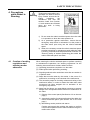
4. Precautions
while Robot is
Running
Warning
Touching the robot while it is in
operation can lead to serious
injury. Please ensure the following
conditions
are
maintained and that the
cautions listed from Section
4.1 and onwards are followed
when any work is being
performed.
1) Do not enter the robot's restricted space when the robot
is in operation or when the motor power is on.
2) As a precaution against malfunction, ensure that an
emergency stop device is activated to cut the power to
the robot motor upon entry into the robot's restricted
space.
3) When it is necessary to enter the robot's restricted space
to perform teaching or maintenance work while the robot
is running, ensure that the steps described in Section 4.3
"Ensuring safety of workers performing jobs within the
robot's restricted space" are taken.
4.1 Creation of working
regulations and
assuring worker
adherence
When entering the robot’s restricted space to perform teaching
or maintenance inspections, set "working regulations" for the
following items and ensure workers adhere to them.
(1) Operating procedures required to run the robot.
(2) Robot speed when performing teaching.
(3) Signaling methods to be used when more than one worker is
to perform work.
(4) Steps that must be taken by the worker in the event of a
malfunction, according to the contents of the malfunction.
(5) The necessary steps for checking release and safety of the
malfunction status, in order to restart the robot after robot
movement has been stopped due to activation of the
emergency stop device
(6) Apart from the above, any steps below necessary to prevent
danger from unexpected robot movement or malfunction of
the robot.
1) Display of the control panel (See Section 4.2 on the next
page.)
2) Assuring the safety of workers performing jobs within the
robot's restricted space (See Section 4.3 on the next
page.)
3) Maintaining worker position and stance
Position and stance that enables the worker to confirm
normal robot operation and to take immediate refuge if a
malfunction occurs.
4) Implementation of measures for noise prevention
5) Signaling methods for workers of related equipment
6) Types of malfunctions and how to distinguish them
Please ensure "working regulations" are appropriate to the robot
type, the place of installation and to the content of the work.
Be sure to consult the opinions of related workers, engineers at
the equipment manufacturer and that of a labor safety consultant
when creating these "working regulations".
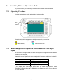
4.2 Display of operation
panel
To prevent anyone other than the worker from accessing the start
switch or the changeover switch by accident during operation,
display something to indicate it is in operation on the operation
panel or teach pendant. Take any other steps as appropriate,
such as locking the cover.
4.3 Ensuring safety of
workers performing
jobs within the robot's
restricted space
When performing jobs within the robot’s restricted space, take
any of the following steps to ensure that robot operation can be
stopped immediately upon a malfunction.
(1) Ensure an overseer is placed in a position outside the
robot’s restricted space and one in which he/she can see all
robot movements, and that he/she is devoted solely to that
task.
c An emergency stop device should be activated
immediately upon a malfunction.
d Do not permit anyone other than the worker engaged for
that job to enter the robot’s restricted space.
(2) Ensure a worker within the robot's restricted space carries
the portable emergency stop switch so he/she can press it
(the emergency button on the teach pendant) immediately if
it should be necessary to do so.
4.4 Inspections before
commencing work
such as teaching
Before starting work such as teaching, inspect the following
items, carry out any repairs immediately upon detection of a
malfunction and perform any other necessary measures.
(1) Check for any damage to the sheath or cover of the external
wiring or to the external devices.
(2) Check that the robot is functioning normally or not (any
unusual noise or vibration during operation).
(3) Check the functioning of the emergency stop device.
(4) Check there is no leakage of air or oil from any pipes.
(5) Check there are no obstructive objects in or near the robot’s
restricted space.
SAFETY PRECAUTIONS
4.5 Release of residual air
pressure
Before disassembling or replacing pneumatic parts, first release
any residual air pressure in the drive cylinder.
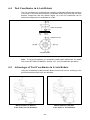
4.6 Precautions for test
runs
Whenever possible, have the worker stay outside of the robot's
restricted space when performing test runs.
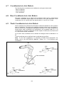
4.7 Precautions for
automatic operation
(1) At start-up
Stay out of the safeguarded space with a safety fence when
starting the robot; in particular, take extra caution in Internal
automatic operation.
Before starting the robot, check the following items as well
as setting the signals to be used and perform signaling
practice with all related workers.
1) Check that there is no one inside the safeguarded space
(with a safety fence).
2) Check that the teach pendant and tools are in their
designated places.
3) Check that no lamps indicating a malfunction on the
robot or related equipment are lit.
(2) Check that the display lamp indicating automatic operation
is lit during automatic operation.
(3) Steps to be taken when a malfunction occurs
Stop the robot's operation by activating the emergency stop
device when it is necessary to enter the safeguarded space
with a safety fence to perform emergency maintenance in
the case of malfunction of the robots or related equipment.
Take any necessary steps such as posting a notice on the
start switch to indicate work is in progress to prevent anyone
from accessing the robot.
4.8 Precautions in repairs
(1) Do not perform repairs outside of the designated range.
(2) Under no circumstances should the interlock mechanism be
removed.
(3) When opening the robot controller's cover for battery
replacement or any other reasons, always turn the robot
controller power off and disconnect the power cable.
(4) Use only spare tools specified in this manual.
5. Daily and Periodical
Inspections
(1) Be sure to perform daily and periodical inspections. Before
starting jobs, always check that there is no problem with the
robot and related equipment. If any problems are found,
take any necessary measures to correct them.
(2) When carrying out periodical inspections or any repairs,
maintain records and keep them for at least 3 years.
6. Management of
Floppy Disks
(1) Carefully handle and store the "Initial settings" floppy disks
packaged with the robot, which store special data
exclusively prepared for your robot.
(2) After finishing teaching or making any changes, always save
the programs and data onto floppy disks.
Making back-ups will help you recover if data stored in the
robot controller is lost due to the expired life of the back-up
battery.
(3) Write the names of each of the floppy disks used for storing
task programs to prevent incorrect disks from loading into
the robot controller.
(4) Store the floppy disks where they will not be exposed to dust,
humidity and magnetic field, which could corrupt the disks or
data stored on them.
7. Safety Codes
The safety standards relating to robot systems are listed below.
As well as observing the safety precautions given in this manual,
ensure compliance with all local and national safety and
electrical codes for the installation and operation of the robot
system.
Standards
ANSI/RIA R15.06-1999
ANSI/UL1740: 1998
CAN/CSA Z434-03
ISO10218-1: 2006
NFPA 79: 2002
8. Battery Recycling
Title
Industrial Robots and Robot Systems--Safety Requirements
Safety for Robots and Robotic Equipment
Industrial Robots and Robot Systems--General Safety Requirements
Robots for industrial environments--Safety requirements--Part 1: Robot
Electrical Standard for Industrial Machinery
DENSO Robot uses lithium batteries.
Discard batteries according to your local and national recycling
law.
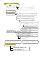
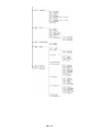
Comprehensive Guidance Flow
for STARTUP MANUAL
Running the robot
Setting up the robot
Mandatory wiring
・ Power cable and Motor & encoder cable (p. 4-1)
・ Emergency Stop and Enable Auto input circuits (p. 5-1)
For the global type of controller
(p. 2-2)
General info about the interface (p. 3-1)
To the next page.
Running the robot from external equipment
Check the I/O allocation mode (p. 13-1)
Notes on using the global type of controller (p. 13-1)
Running in mini I/O dedicated mode (p. 13-2)
Running in standard mode (p. 13-6)
Running in compatible mode (p. 13-10)
I/O allocation tables (p. 13-14)
Hand I/O (common to all modes) (p. 13-14)
Mini I/O (on standard and global types) (p. 13-15)
If an extension
board(s) is mounted:
Mini I/O board (p. 13-17)
Parallel I/O board (p. 13-19)
DeviceNet slave board (p. 13-23)
CC-Link board (p. 13-26)
PROFIBUS-DP slave board (p. 13-35)
DeviceNet master board (p. 13-38)
S-Link V master board (p. 13-39)
Manual to Automatic operation
Basics of operation
Coordinates and position data (p. 6-1)
Handling the teach pendant (p. 7-1)
Teaching (p. 7-1)
Creating programs
Basic knowledge and main commands (p. 9-1)
Programming with teach pendant (p. 10-1)
Programming with WINCAPSIII (p. 11-1)
License certificate for WINCAPSIII
(p. 11-2)
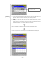
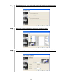
Starting WINCAPSIII (p. 11-5)
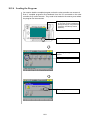
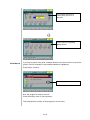
Creating a new project (p. 11-7)
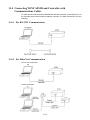
Connecting with PC and transferring data
in WINCAPSIII (p. 11-12)
Starting programs
Simulation in WINCAPSIII (p. 12-1)
Running in Teach check mode (p. 12-3)
Running in Internal auto mode (p. 12-8)
Stopping (p. 12-12)
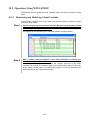
Monitoring and manipulating I/Os
(p. 14-1)
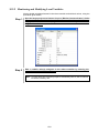
Monitoring and modifying variable
values (p. 15-1)
Advanced usage
Optimizing use conditions (p. 16-1)
Various statements (p. 17-1)
Contents
Preface...................................................................................................................................................i
How the documentation set is organized.............................................................................................ii
How this book is organized .................................................................................................................iii
SAFETY PRECAUTIONS
Part 1 Preparation for Installation
Chapter 1 Configuration of the Robot System .................................................................................1-1
1.1
Configurators........................................................................................................................... 1-1
1.2
Standard Components ............................................................................................................ 1-2
1.3
Optional Components.............................................................................................................. 1-3
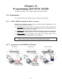
Chapter 2 General Information about RC7M Controller .................................................................2-1
2.1
Controller Model Name on Nameplate.................................................................................. 2-1
2.2
Differences between Global and Standard Types of Robot Controllers .............................. 2-2
2.2.1
Deadman Switch Function (Enable Switch Function).................................................... 2-2
2.2.2
"Single Point of Control" Function ................................................................................... 2-3
Chapter 3 General Information about the Interface ........................................................................3-1
3.1
Types and General Information about Mini I/O Signals ...................................................... 3-1
3.1.1
Types of Mini I/O Signals on the Standard Type of Controller ...................................... 3-1
3.1.2
Types of Mini I/O Signals on the Global Type of Controller ........................................... 3-2
3.2
3.2.1
3.3
Overview of I/O Extension Boards ......................................................................................... 3-3
I/O Extension Boards Available ........................................................................................ 3-3
Combination of I/O Extension Boards and Allocation Mode................................................ 3-4
3.3.1
I/O Allocation in Individual Allocation Modes ................................................................. 3-5
3.3.2
Functions in Individual Allocation Modes ....................................................................... 3-5
3.4
Mini I/O Functions in Compatible, Standard, or All User I/O Mode................................... 3-6
3.5
Requirements for Interface Setting ....................................................................................... 3-6
3.5.1
Configuring the I/O Allocation Mode Parameter............................................................. 3-6
3.5.2
Setting up the I/O Power Source (+24 VDC).................................................................... 3-6
3.6
Configuring the I/O Allocation Mode Parameter .................................................................. 3-7
3.6.1
With Teaching Pendant ..................................................................................................... 3-7
3.6.2
Method for setting from WINCAPSIII ............................................................................. 3-7
3.7
Setting Up Mini I/O Power Source....................................................................................... 3-10
3.8
Setting up Parallel I/O Board Power Source....................................................................... 3-11
3.9
I/O Port Map and Allocation................................................................................................. 3-12
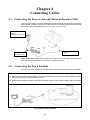
Chapter 4 Connecting Cables ...........................................................................................................4-1
4.1
Connecting the Power Cable and Motor & Encoder Cable .................................................. 4-1
4.2
Connecting the Teach Pendant............................................................................................... 4-1
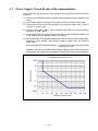
4.3
Power Supply Circuit Breaker (Recommendation)............................................................... 4-2
4.4
Wiring of Primary Power Source............................................................................................ 4-3
Chapter 5 Wire Connection for System Input Signals .....................................................................5-1
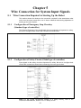
5.1
Wire Connection Required in Starting Up the Robot ........................................................... 5-1
5.1.1
Configuration of Emergency Stop Circuitry (Standard type of controller) .................. 5-1
5.1.2
Configuration of Safety Circuit (Global type of controller)............................................. 5-1
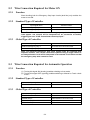
5.2
Wire Connection Required for Motor ON .............................................................................. 5-2
5.2.1
Function.............................................................................................................................. 5-2
5.2.2
Standard Type of Controller.............................................................................................. 5-2
5.2.3
Global Type of Controller .................................................................................................. 5-2
5.3
Wire Connection Required for Automatic Operation............................................................ 5-2
5.3.1
Function.............................................................................................................................. 5-2
5.3.2
Standard Type of Controller.............................................................................................. 5-2
5.3.3
Global Type of Controller .................................................................................................. 5-2
Part 2 Robot Running
Chapter 6 Coordinates......................................................................................................................6-1
6.1
Coordinates in 4-Axis Robots ................................................................................................. 6-1
6.2
Base Coordinates in 4-Axis Robots ........................................................................................ 6-1
6.3
Work Coordinates in 4-Axis Robots ....................................................................................... 6-1
6.4
Tool Coordinates in 4-Axis Robots.......................................................................................... 6-2
6.5
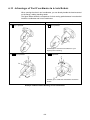
Advantages of Tool Coordinates in 4-Axis Robots................................................................. 6-2
6.6
Position Data Handled by 4-Axis Robots............................................................................... 6-3
6.6.1
Shoulder Figures of 4-Axis Robots ................................................................................... 6-3
6.7
Coordinates in 6-Axis Robots ................................................................................................. 6-4
6.8
Base Coordinates in 6-Axis Robots ........................................................................................ 6-4
6.9
Work Coordinates in 6-Axis Robots ....................................................................................... 6-4
6.10
Tool Coordinates in 6-Axis Robots.......................................................................................... 6-5
6.11
Advantages of Tool Coordinates in 6-Axis Robots................................................................. 6-6
6.12
Position Data Handled by 6-Axis Robots............................................................................... 6-7
6.12.1
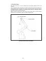
Figures of the Shoulder, Elbow, and Wrist in 6-Axis Robots .......................................... 6-8
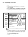
Chapter 7 Preparations for Teaching ...............................................................................................7-1
7.1
Handling the Teach Pendant.................................................................................................. 7-1
7.1.1
Holding the Teach Pendant and the Deadman Switch ................................................... 7-1
7.1.2
Names of Keys, Buttons, and Switches on the Teach Pendant ........................................ 7-2
7.2
Operation Modes ..................................................................................................................... 7-4
7.2.1
Manual Mode...................................................................................................................... 7-4
7.2.2
Teach Check Mode ............................................................................................................. 7-4
7.2.3
Auto Mode........................................................................................................................... 7-4
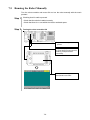
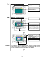
7.3
Switching Between Operation Modes.................................................................................... 7-5
7.3.1
Operating Procedure.......................................................................................................... 7-5
7.3.2
Relationship between Operation Modes and Enable Auto Input Signal ....................... 7-5
7.4
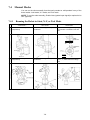
Manual Modes ......................................................................................................................... 7-6
7.4.1
Running the Robot in Joint, X-Y, or Tool Mode ............................................................... 7-6
7.4.2
Switching to Manual Mode ............................................................................................... 7-7
7.5
Running the Robot Manually ................................................................................................. 7-9
Chapter 8 Teaching...........................................................................................................................8-1
8.1
What is Teaching? ................................................................................................................... 8-1
8.2
Global Variables Available in Teaching ................................................................................. 8-1
8.3
Teaching to Position Variables ............................................................................................... 8-2
8.4
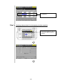
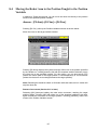
Moving the Robot Arm to the Position Taught to the Position Variable ............................. 8-7
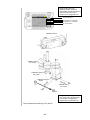
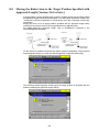
8.5
Moving the Robot Arm to the Target Position Specified with Approach Length
[Version 2.61 or later].............................................................................................................. 8-8
Part 3 Simple Programming
Chapter 9 Basic Knowledge of Programming...................................................................................9-1
9.1
Features of PAC Language ..................................................................................................... 9-1
9.2
Statement and Line................................................................................................................. 9-1
9.3
Name ........................................................................................................................................ 9-1
9.4
Maximum Number of Loadable Programs ............................................................................ 9-2
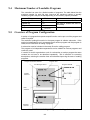
9.5
Overview of Program Configuration ...................................................................................... 9-2
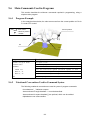
9.6
Main Commands Used in Programs ...................................................................................... 9-3
9.6.1
Program Example .............................................................................................................. 9-3
9.6.2
Notational Conventions Used in Command Syntax........................................................ 9-3
9.6.3
Declaring Program Names (PROGRAM command) ............................................................. 9-4
9.6.4
Obtaining an Arm Semaphore (TAKEARM command) ...................................................... 9-4
9.6.5
Stopping a Program (END command)................................................................................ 9-4
9.6.6
Specifying the Arm Speed (SPEED command).................................................................. 9-4
9.6.7
Comment (REM command) ................................................................................................. 9-4
9.6.8
Movement to the Specified Coordinates (MOVE command) ............................................. 9-5
9.7
Movement in the Z-Axis Direction (APPROACH and DEPART commands)..................... 9-8
9.7.1
Approach in the Hand Direction (APPROACH command)............................................. 9-8
9.7.2
Dodging Movement in the Hand Direction (DEPART command) .................................. 9-9
9.8
Scope of Variables.................................................................................................................. 9-10
9.8.1
Global Variable................................................................................................................. 9-11
9.8.2
Local Variable................................................................................................................... 9-12
9.9
Initiating from External Equipment ................................................................................... 9-13
Chapter 10 Programming with Teach Pendant..............................................................................10-1
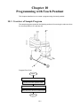
10.1
Overview of Sample Program............................................................................................... 10-1
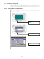
10.2
Creating a Program............................................................................................................... 10-2
10.2.1
Entering a New Program Name ..................................................................................... 10-2
10.2.2
Entering Program Codes ................................................................................................. 10-3
10.2.3
Compiling the Program ................................................................................................... 10-7
10.2.4
Loading the Program....................................................................................................... 10-9
Chapter 11 Programming with WINCAPSIII ................................................................................ 11-1
11.1
Preparation ............................................................................................................................ 11-1
11.1.1
WINCAPSIII Available in Three Versions ..................................................................... 11-1
11.1.2
Appearance of CD-ROMs (CD Label) ............................................................................. 11-1
11.1.3
License Certificate (with User ID).................................................................................. 11-2
11.1.4
Checking the WINCAPSIII Version on PC Screen........................................................ 11-2
11.1.5
Notes on Updating ........................................................................................................... 11-3
11.1.6
Entry of License Key........................................................................................................ 11-3
11.2
Overview of Sample Program............................................................................................... 11-4
11.3
Creating a Program............................................................................................................... 11-5
11.3.1
Starting up WINCAPSIII ............................................................................................... 11-5
11.3.2
Creating a New Project ................................................................................................... 11-5
11.3.3
Creating a Program ......................................................................................................... 11-8
11.3.4
Entering and Saving Program Code............................................................................. 11-10
11.3.5
Compiling the Program ................................................................................................. 11-11
11.4
Connecting WINCAPSIII and Controller with Communications Cables ....................... 11-13
11.4.1
For RS-232C Communication ....................................................................................... 11-13
11.4.2
For EtherNet Communication ...................................................................................... 11-13
11.5
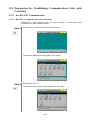
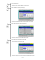
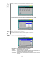
Preparation for Establishing Communications Link with Controller............................. 11-14
11.5.1
For RS-232C Communication ....................................................................................... 11-14
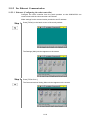
11.5.2
For Ethernet Communication ....................................................................................... 11-19
11.6
Transmitting Data with WINCAPSIII............................................................................... 11-26
11.6.1
Preparation in the Controller (Precautions for Transferring Data)........................... 11-26
11.6.2
Transferring Program Data to the Robot Controller................................................... 11-27
Part 4 Program Verification
Chapter 12 Starting a Program......................................................................................................12-1
12.1
Simulating a Program Operation with WINCAPS III ....................................................... 12-1
12.1.1
Opening an Arm View...................................................................................................... 12-1
12.1.2
Monitoring the Robot Controller from WINCAPSIII .................................................... 12-1
12.1.3
Placing the Robot Controller in Machine Lock.............................................................. 12-2
12.1.4
Starting the Program ...................................................................................................... 12-2
12.2
Starting a Program in Teach Check Mode........................................................................... 12-3
12.2.1
Teach Check...................................................................................................................... 12-3
12.2.2
Selecting a Program to be Executed............................................................................... 12-4
12.2.3
Step Check........................................................................................................................ 12-4
12.2.4
Cycle Check ...................................................................................................................... 12-6
12.3
Starting a Program in Internal Auto Mode......................................................................... 12-8
12.3.1
Placing the Robot in Auto Mode...................................................................................... 12-8
12.3.2
Selecting the Program to be Executed ........................................................................... 12-8
12.3.3
Single-Step Start.............................................................................................................. 12-9
12.3.4
Single-Cycle Start .......................................................................................................... 12-10
12.3.5
Continuous Start............................................................................................................ 12-11
12.4
Robot Stop............................................................................................................................ 12-12
12.4.1
Cycle Stop [F3] ............................................................................................................... 12-12
12.4.2
Step Stop [F2]................................................................................................................. 12-12
12.4.3
Halt [F1], [STOP]........................................................................................................... 12-12
12.4.4
Emergency Stop (Robot Stop) ....................................................................................... 12-13
Chapter 13 Running the Robot from External Equipment............................................................13-1
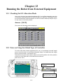
13.1
Checking the I/O Allocation Mode........................................................................................ 13-1
13.2
Notes on Using the Global Type of Controller .................................................................... 13-1
13.3
Running in Mini I/O Dedicated Mode.................................................................................. 13-2
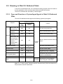
13.3.1
Types and Functions of System Input Signals in Mini I/O Dedicated Mode............... 13-2
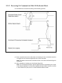
13.3.2
Processing I/O Commands in Mini I/O Dedicated Mode............................................... 13-3
13.3.3
Types and Functions of System Output Signals in Mini I/O Dedicated Mode............ 13-5
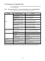
13.4
Running in Standard Mode .................................................................................................. 13-6
13.4.1
Types and Functions of System Input Signals in Standard Mode ............................... 13-6
13.4.2
Processing I/O Commands in Standard Mode ............................................................... 13-7
13.4.3
13.5
Types and Functions of System Output Signals in Standard Mode ........................... 13-9
Running in Compatible Mode .......................................................................................... 13-10
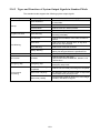
13.5.1
Types and Functions of System Input Signals in Compatible Mode ........................ 13-10
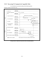
13.5.2
Processing I/O Commands in Compatible Mode.........................................................13-11
13.5.3
Types and Functions of System Output Signals in Compatible Mode...................... 13-13
13.6
I/O Allocation Tables......................................................................................................... 13-14
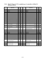
13.6.1
Hand I/O (CN9): Common to All Modes ..................................................................... 13-14
13.6.2
Mini I/O Board (CN5 on standard type of controller) in Mini I/O Dedicated Mode . 13-15
13.6.3
Mini I/O Board (CN5 on global type of controller) in Mini I/O Dedicated Mode ...... 13-16
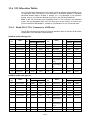
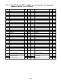
13.6.4
Mini I/O Board (CN5 on standard type of controller) in Compatible, Standard and All
User I/O Modes............................................................................................................ 13-17
13.6.5
Mini I/O Board (CN5 on global type of controller) in Compatible, Standard, and All User
I/O Modes..................................................................................................................... 13-18
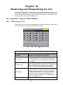
Chapter 14 Monitoring and Manipulating the I/Os .......................................................................14-1
14.1
Operation Using the Teach Pendant.................................................................................. 14-1
14.1.1
Monitoring the I/Os ....................................................................................................... 14-1
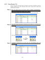
14.1.2
Turning Dummy Inputs ON/OFF ................................................................................. 14-2
14.2
Operation Using WINCAPSIII .......................................................................................... 14-4
14.2.1
Monitoring I/O Status ................................................................................................... 14-4
14.2.2
Using Dummy I/Os........................................................................................................ 14-5
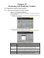
Chapter 15 Monitoring and Modifying Variables...........................................................................15-1
15.1
Operation Using the Teach Pendant.................................................................................. 15-1
15.1.1
Monitoring and Modifying Global Variables ................................................................ 15-1
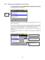
15.1.2
Monitoring and Modifying Local Variables .................................................................. 15-2
15.1.3
Modifying the Number of Variables Used .................................................................... 15-5
15.2
Operation Using WINCAPSIII .......................................................................................... 15-7
15.2.1
Monitoring and Modifying Global Variables ................................................................ 15-7
15.2.2
Monitoring and Modifying Local Variables .................................................................. 15-8
15.2.3
Modifying the Number of Variables to be Used ........................................................... 15-9
Part 5 Advanced Usage
Chapter 16 Optimizing Use Conditions .........................................................................................16-1
16.1
Setting Robot Installation Condition (Floor-Mount or Overhead-Mount, for 6-Axis Robot)...
........................................................................................................................................ 16-1
16.1.1
Purpose of Setting Robot Installation Condition ......................................................... 16-1
16.1.2
Setting with the Teach Pendant ................................................................................... 16-1
16.1.3
Setting with WINCAPSIII ............................................................................................ 16-2
16.2
Control Sets of Motion Optimization ................................................................................. 16-3
16.2.1
Control Set 0.................................................................................................................. 16-3
16.2.2
Control Set 1.................................................................................................................. 16-3
16.2.3
Control Set 2.................................................................................................................. 16-4
16.2.4
Control Set 3.................................................................................................................. 16-4
16.3
How to Set Optimal Load Capacity Initializing ................................................................ 16-5
16.3.1
Setting with Teach Pendant.......................................................................................... 16-5
16.3.2
Setting with WINCAPSIII ............................................................................................ 16-6
16.4
How to Set Optimal Load Capacity Initializing [Version 1.4 or later] ............................. 16-7
16.4.1
Setting with Teach Pendant.......................................................................................... 16-7
16.4.2
Setting with WINCAPSIII ............................................................................................ 16-8
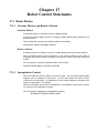
Chapter 17 Robot Control Statements ...........................................................................................17-1
17.1
Robot Motion....................................................................................................................... 17-1
17.1.1
Absolute Motion and Relative Motion .......................................................................... 17-1
17.1.2
Interpolation Control .................................................................................................... 17-1
17.2
Robot Control Command .................................................................................................... 17-3
17.2.1
DRIVEA ......................................................................................................................... 17-3
17.2.2
DRIVE............................................................................................................................ 17-4
17.2.3
DRAW ............................................................................................................................ 17-5
17.3
Practice Exercises............................................................................................................... 17-7
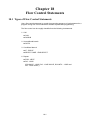
Chapter 18 Flow Control Statements.............................................................................................18-1
18.1
Types of Flow Control Statements ..................................................................................... 18-1
18.2
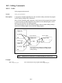
Calling Commands ............................................................................................................. 18-2
18.2.1
CALL.............................................................................................................................. 18-2
18.2.2
GOSUB .......................................................................................................................... 18-3
18.3
Unconditional Branch Commands..................................................................................... 18-4
18.3.1
18.4
GOTO............................................................................................................................. 18-4
Conditional Branch Commands ......................................................................................... 18-5
18.4.1
IF…END IF ................................................................................................................... 18-5
18.4.2
SELECT CASE.............................................................................................................. 18-6
18.5
Repeat Commands.............................................................................................................. 18-7
18.5.1
FOR…NEXT .................................................................................................................. 18-7
18.5.2
DO…LOOP .................................................................................................................... 18-8
18.6
Practice Exercise............................................................................................................... 18-10
Chapter 19 Input/Output Control Statements...............................................................................19-1
19.1
Time Control ....................................................................................................................... 19-1
19.1.1
DELAY ........................................................................................................................... 19-1
19.1.2
WAIT .............................................................................................................................. 19-1
19.2
I/O Port Control .................................................................................................................. 19-2
19.2.1
SET ................................................................................................................................ 19-2
19.2.2
RESET ........................................................................................................................... 19-2
19.3
Practice Exercises............................................................................................................... 19-3
Chapter 20 Library .........................................................................................................................20-1
20.1
Using Library Programs..................................................................................................... 20-1
20.1.1
What are Library Programs? ........................................................................................ 20-1
20.1.2
Program Bank ............................................................................................................... 20-1
20.1.3
Library Classifications .................................................................................................. 20-1
20.1.4
Importing a Library Program ....................................................................................... 20-2
20.2
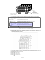
Using Palletizing Library................................................................................................... 20-4
20.2.1
What Is Palletizing? ...................................................................................................... 20-4
20.2.2
Simplified Palletizing Library ...................................................................................... 20-4
20.2.3
Simplified Palletizing Program "PRO1"....................................................................... 20-7
Appendices
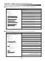
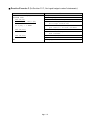
Appendix 1 Sample Answers to Practice Exercises
Appendix 2 Commands Listed According to Functions
Appendix 3 Menu Tree of Commands on Teach Pendant
Appendix 4 Program Samples
Appendix 5 Glossary
Part 1
Preparation for Installation
Chapter 1 Configuration of the Robot System
Chapter 2 General Information about RC7M Controller
Chapter 3 General Information about the Interface
Chapter 4 Connecting Cables
Chapter 5 Wire Connection for System Input Signals
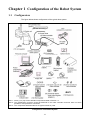
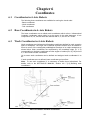
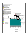
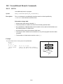
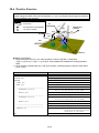
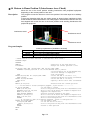
Chapter 1 Configuration of the Robot System
1.1
Configurators
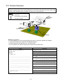
The figure below shows configurators of the typical robot system.
Note 1: Items (1) to (16) are the standard components listed in Section 1.2.
Note 2: The pendantless connector should be attached to the robot controller connector when no teach
pendant or mini-pendant is connected.
Note 3: The components illustrated above are typical models or parts.
Configurators of the Robot System
1-1
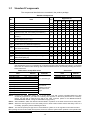
1.2
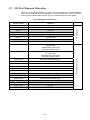
Standard Components
The components listed below are contained in the product package.
Standard Components
Applicable to:
No.
(1)
(2)
(3)
(4)
(5)
(6)
(7)
(8)
(9)
(10)
(11)
(12)
(13)
(14)
(15)
(16)
Item
Q'ty
Robot unit
1
Robot controller
1
Power cable (5 m)
1
Motor & encoder cable (Note 1) (Option)
1
Manuals
1 set
("Manual Pack CD" and "Safety Precautions")
NetwoRC CD (containing WINCAPSIII beta
1
version)
Spare fuses for robot controller
3
(1.3A x 2 pcs, 3.2A x 1 pc)
Initialization floppy disk (1.44 MB format) (Note 2)
1
Pendantless connector (Dummy connector) (not
1
contained in UL-Listed robot systems)
Connector set for hand control signals
1 set
(for CN20 and CN21)
Direction indicator label (Note 3)
1
Warning label (Note 4)
1
Spare output IC for robot controller
1
Dowel pins (internally threaded positioning pin and
1 set
diamond-shaped pin)
Air regulator (Note 5)
1
Short sockets for robot controller
2
HS
HM
XYC
VP
VS
VH
XR
series series series series series series series
√
√
√
√
√
√
√
√
√
√
√
√
√
√
√
√
√
√
√
√
√
√
√
√
√
√
√
√
√
√
√
√
√
√
√
√
√
√
√
√
√
√
√
√
√
√
√
√
√
√
√
√
√
√
√
√
√
√
√
√
√
√
√
√
√
√
√
√
√
√
√
√
√
√
√
√
√
√
√
√
√
√
√
√
√
√
√
√
√
√
√
√
√
--
√
√
--
--
-√
√
√
√
√
-√
-√
-√
-√
Note 1: Choose and order a motor & encoder cable from the table below. The 20-m motor & encoder cable
(standard/splash-proof) is not available for controllers equipped with extended-joint options or UL-Listed
robot units. The internal cable bending radius shall at least be 200 mm. Excessively bending will result in
broken lead wires.
Robot series except XYC series
Item
Standard cable
Standard cable
Standard cable
Standard cable
Standard cable
Splash-proof cable
Splash-proof cable
Splash-proof cable
Splash-proof cable
Splash-proof cable
2m
4m
6m
12 m
20 m
2m
4m
6m
12 m
20 m
XYC series
Part No.
Remarks
410141-4400
410141-3611
410141-3621 For standard type
410141-3631
410141-4440
410141-4420
410141-3681 For dust- &
splash-proof type
410141-3691 and cleanroom
410141-3701 type
410141-4460
Item
Standard cable
Standard cable
4m
6m
Part No.
410149-0960
410149-0970
Note 2: Preserve the initialization floppy disk in a safe place. The disk contains CALSET-related arm data
exclusively prepared for your robot. If a memory error appears on the teach pendant due to a memory
failure, use the disk to load the arm data to the robot controller. (Refer to the INSTALLATION &
MAINTENANCE GUIDE, "Using the Initialization Floppy Disk.")
Note 3: After installation, attach the direction indicator label in a position on the robot unit that can be easily seen.
Note 4: Attach the warning label on the robot safety fence or other location where workers will easily notice it. If
necessary, prepare a plate for attaching the label.
Note 5: The dust- & splash-proof type has no Z-axis balance cylinder, so no air regulator comes with the robot.
When placing an order for UL-Listed robot systems, be sure to order the optional teach pendant or mini-pendant also
which is essential to UL-Listed ones.
1-2
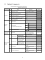
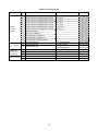
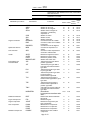
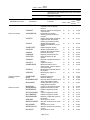
1.3
Optional Components
The table below lists the optional components.
Optional Components (1)
Classification No.
1
I/O cables
Item
Remarks
Standard I/O cable set
1-1
I/O cable for "Mini I/O" (68 pins)
1-2
I/O cable for "HAND I/O"
2
I/O cable for "Parallel I/O board" (96 pins)
3
I/O cable for "SAFETY I/O" (36 pins)
(Only for global type)
4
Teach pendant
(8 m) Incl. Nos. 1-1 and 1-2.
410149-0940
(15 m) Incl. Nos. 1-1 and 1-2.
410149-0950
(8 m)
410141-2700
(15 m)
410141-2710
(8 m)
410141-1740
(15 m)
410141-1750
(8 m)
410141-3050
(15 m)
410141-3060
(8 m)
410141-3580
(15 m)
410141-3590
(4 m) With cable
410100-1570
(8 m) With cable
410100-1580
(12 m) With cable
410100-1590
(4 m)
Operation
devices
5
Mini-pendant kit
(incl. cable and WINCAPSIII Light)
(8 m)
(12 m)
6
Programming
support tool
7
8
Pendant extension cable
11
410109-0400
Japanese indication
410109-0410
English indication
410109-0420
Japanese indication
410109-0430
English indication
410109-0440
(4 m)
For TP, MP
410141-3710
(8 m)
For TP, MP
410141-3720
NPN
410010-3320
PNP
410010-3330
Shipped as individual
boards (supply part)
NPN
410010-3340
PNP
410010-3350
For Slave station
410010-3370
For Master station
410010-3380
For Master & slave station
410010-3390
For Slave station
410010-3400
Shipped as individual
boards (supply part)
10
English indication
Shipped as installed
on the controller
DeviceNet board
Optional boards
for RC7M
controller
410109-0390
410090-0980
Shipped as installed
on the controller
9
Japanese indication
CD-ROM
(common to the languages-Japanese, English, German,
Korean, and Chinese)
WINCAPSIII
Parallel I/O board
Part No.
CC-Link board
Conveyor tracking board
1-3
For Master station
410010-3410
For Master & slave station
410010-3480
Shipped as installed on the
controller
410010-3430
Shipped as individual boards
(supply part)
410010-3440
Shipped as installed on the
controller
410010-3460
Shipped as individual boards
(supply part)
410010-3470
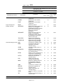
Optional Components (2)
Classification No.
12
13
Optional
functions
(For customerprocured
extended
boards etc.)
14
15
Optional box
CD Manuals
Printed
manuals
(option)
Item
Remarks
Optional function for RS-232C board
Board manufacturer: CONTEC CO., LTD.
Model: COM-2P(PCI)H
Optional function for S-LINK V board
Board manufacturer: SUNX CO., LTD.
Model: SL-VPCI
Optional function for PROFIBUS-DP slave
board
Board manufacturer: Hilscher GmbH
Model: CIF50-DPS\DENSO
EtherNet/IP function
Board manufacturer: Hilscher GmbH
Model: CIFX 50-RE\DENSO
16
Optional function for memory extension
17
Controller protection box
18
19
20-a
20-b
20-c
20-d
20-e
20-f
20-g
C-a
C-b
C-c
C-d
C-e
C-f
C-g
C-a-1
C-b-1
C-c-1
C-d-1
C-e-1
C-f-1
C-g-1
C-2
C-3
D-a
D-b
D-c
D-d
D-e
D-f
D-g
Shipped after integrated in the
controller
Added when the board is
purchased as a spare part
Shipped after integrated in the
controller
Added when the board is
purchased as a spare part
Shipped after integrated in the
controller
Added when the board is
purchased as a spare part
Shipped after integrated in the
controller
Added when the board is
purchased as a spare part
Extension only upon controller
shipment
(Only program area expandable
from 3.25 MB to 5.5 MB)
Part No.
410006-0260
410006-0270
410006-0280
410006-0290
410006-0300
410006-0310
410006-0800
410006-0810
410006-0320
410181-0090
I/O conversion box
Manual Pack CD
Full set of instruction manuals for HS-G
Full set of instruction manuals for HM-G
Full set of instruction manuals for VP-G
Full set of instruction manuals for VS-G
Full set of instruction manuals for VM-G
Full set of instruction manuals for XYC-4G
Full set of instruction manuals for XR-G
Basic set of instruction manuals for HS-G
Basic set of instruction manuals for HM-G
Basic set of instruction manuals for VP-G
Basic set of instruction manuals for VS-G
Basic set of instruction manuals for VM-G
Basic set of instruction manuals for XYC-4G
Basic set of instruction manuals for XR-G
GENERAL INFORMATION ABOUT ROBOT
GENERAL INFORMATION ABOUT ROBOT
GENERAL INFORMATION ABOUT ROBOT
GENERAL INFORMATION ABOUT ROBOT
GENERAL INFORMATION ABOUT ROBOT
GENERAL INFORMATION ABOUT ROBOT
GENERAL INFORMATION ABOUT ROBOT
RC7M CONTROLLER MANUAL
ERROR CODE TABLES
Extension set of instruction manuals for HS-G
Extension set of instruction manuals for HM-G
Extension set of instruction manuals for VP-G
Extension set of instruction manuals for VS-G
Extension set of instruction manuals for VM-G
Extension set of instruction manuals for
XYC-4G
Extension set of instruction manuals for
XR-G
1-4
For interchangeability with RC5
controller
Contained in the robot package.
Incl. Nos. C-a and D-a.
Incl. Nos. C-b and D-b.
Incl. Nos. C-c and D-c.
Incl. Nos. C-d and D-d.
Incl. Nos. C-e and D-e.
Incl. Nos. C-f and D-f.
Incl. Nos. C-g and D-g.
Incl. Nos. C-a-1, C-2 and C-3.
Incl. Nos. C-b-1, C-2 and C-3.
Incl. Nos. C-c-1, C-2 and C-3.
Incl. Nos. C-d-1, C-2 and C-3.
Incl. Nos. C-e-1, C-2 and C-3.
Incl. Nos. C-f-1, C-2 and C-3.
Incl. Nos. C-f-1, C-2 and C-3.
For HS-G
For HM-G
For VP-G
For VS-G
For VM-G
For XYC-4G
For XR-G
For RC7M controller
Incl. Nos. D-a-1, and D-2 to D-7.
Incl. Nos. D-b-1, and D-2 to D-7.
Incl. Nos. D-c-1, and D-2 to D-7.
Incl. Nos. D-d-1, and D-2 to D-7.
Incl. Nos. D-e-1, and D-2 to D-7.
410181-0100
410002-2661
410009-0360
410009-0304
410009-0320
410009-0300
410009-0280
410009-0430
410009-0870
410009-0260
410009-0240
410009-0220
410009-0200
410009-0180
410009-0410
410009-0850
410002-2610
410002-2570
410002-2530
410002-2490
410002-2450
410002-2770
410002-3210
410002-2430
410002-3370
410009-0140
410009-0120
410009-0100
410009-0080
410009-0060
Incl. Nos. D-f-1, and D-2 to D-7. 410009-0390
Incl. Nos. D-g-1, and D-2 to D-7. 410009-0830
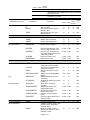
Optional Components (3)
Classification No.
Printed
manuals
(option)
For robot unit
Piping and
wiring set for
robot hand
Optional stand
Item
Remarks
Part No.
D-a-1 INSTALLATION & MAINTENANCE GUIDE
For HS-G
410002-2630
D-b-1 INSTALLATION & MAINTENANCE GUIDE
For HM-G
410002-2590
410002-2550
D-c-1 INSTALLATION & MAINTENANCE GUIDE
For VP-G
D-d-1 INSTALLATION & MAINTENANCE GUIDE
For VS-G
410002-2510
D-e-1 INSTALLATION & MAINTENANCE GUIDE
For VM-G
410002-2470
D-f-1 INSTALLATION & MAINTENANCE GUIDE
For XYC-4G
410002-2790
D-g-1 INSTALLATION & MAINTENANCE GUIDE
For XR-G
410002-3230
D-2
STARTUP MANUAL
410002-2750
D-3
SETTING-UP MANUAL
410002-3310
D-4
PROGRAMMER'S MANUAL I
410002-3330
D-5
PROGRAMMER'S MANUAL II
410002-3350
D-6
Panel Designer USER’S MANUAL
D-7
OPTIONS MANUAL
For RC7M controller
410002-2650
21-a
Flange kit (For HS)
For HS-G series
410329-0060
21-b
Flange kit (For HM)
21-g
Valve assembly (For XR-G)
22-g
Cable kit for robot hand control (For XR-G)
23-g
Cable kit for robot hand control (For XR-G)
410002-6480
For 10 kg payload
410329-0070
For 20 kg payload
410329-0080
Quad manifold valve
410640-0230
410879-0470
2m
410870-3350
24
Full-range stand(For XR-G)
411759-0010
25
Half-range stand(For XR-G)
411759-0020
1-5
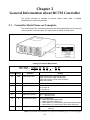
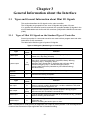
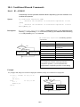
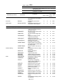
Chapter 2
General Information about RC7M Controller
The RC7M controller is available in several models which differ in detailed
specifications to match robot models.
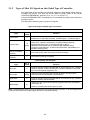
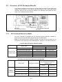
2.1
Controller Model Name on Nameplate
The model name of the controller is printed on the nameplate attached to the rear side
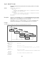
of the controller as shown below. The model name is coded as listed below.
Coding of Controller Model Name
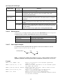
RC7M - VSG 6 B A
(a)
Position
Code
sample
(a)
VSG
(b)
(b)
(c)
- B P
(d) (e)
Denotes:
(f)
(g)
Coding
Robot model name
VMG: VM-G series, VSG: VS-G series,
VPG: VP-G series, HMG: HM-G series,
HSG: HS-G series, XYCG: XYC-4G series ,
XRG: XR-G series
6
No. of controllable axes
4: 4 axes, 5/6: 5 or 6 axes, 6: 6 axes
(c)
B
Engineering symbol 1
A: Encoder A
B: Encoder B
C: Encoder C
(d)
A
Engineering symbol 2
A: 24V brake
Engineering symbol 3
Blank: 200 VAC power
A:
100 VAC power
(e)
(f)
B
Controller type (Note)
Blank: Standard type
B: Global type (with safety board)
C: Global type (with safety box)
D: Global type in UL-Listed robot system (with safety board)
E: Global type in UL-Listed robot system (with safety box)
(g)
P
I/O type
Blank or N: NPN I/O
P:
PNP I/O
(Note) For the differences between the global and standard types, see the next page.
2-1
2.2
Differences between Global and Standard Types of Robot
Controllers
The global type of the robot controller has either a safety board or safety box which the
standard type has not. Described below are the functional differences between the
global and standard types.
2.2.1
Deadman Switch Function (Enable Switch Function)
The global type controls the deadman switch provided on the teach pendant or
mini-pendant in a partially different way than the standard type does. When reading the
instruction manuals that are prepared for the standard type, be careful with the
following differences.
(1) Location of deadman switches (enable switches) on the teach pendant and mini-pendant
Deadman switch
(Enable switch)
Deadman
switch
(Enable
switch)
Teach pendant
Mini-pendant
(2) Difference in deadman switch operation
The table below lists the functional differences of the teach pendant and mini-pendant
between the global and standard types in Manual mode and Teach check mode.
Standard type
(described in the instruction manuals)
Global type
(1) Unless the deadman switch is held down, you
can neither operate the robot nor turn the motor
power ON.
(1) Unless the deadman switch is held down, you
cannot operate the robot, but you can turn the
motor power ON.
(2) When the robot is in operation, releasing the
deadman switch will stop not only the robot but
also turn the motor power OFF.
(2) When the robot is in operation, releasing the
deadman switch will stop the robot but not turn
the motor power OFF (servo lock).
2-2
2.2.2
"Single Point of Control" Function
The global type of the robot controller supports the "single point of control" function,
while other types do not.
This function limits the robot-start that other equipments except specified one device
(for example: Teach pendant) cannot enable to start the robot.
The "single point of control" function, which is one of the robot safety functions, limits
the robot control sources (command sources) to only one. This function is specified by
the parameter "Single point of control" that limits the control to either "Internal Auto" or
"External Auto" limited mode.
Internal Auto limited mode
The "Auto mode" is limited to the "Internal Auto" limited mode in which a program start
can be triggered from the teach pendant, but cannot from external equipment.
External Auto limited mode
The "Auto mode" is limited to the "External Auto" limited mode in which a program start
can be triggered from external equipment, but cannot from the teach pendant.
Note: In this mode, the teach pendant operation panel editor "Panel Designer" cannot
be used in External Auto.
Setting the Internal/External Auto Limited Mode Parameters
Using the teach pendant, set the parameters with the following access.
Note 1: The "Internal Auto Limited Mode" is the factory default.
Note 2: The global type displays letter "A" following the robot type on the teach pendant
screen.
Access: [Top screen]—[F4 I/O]—[F6 Aux.]—[F1 Set H/W]—[F3 Jump To]—"31"
In Ver. 2.3 or later:
Access: [Top screen]—[F4 I/O]—[F6 Aux.]—[F4 Int/Ext]
"A" displayed
"A" displayed
Setting on the "I/O Hardware Settings" window
Setting on the "Single point of control" window
(Ver. 2.3 or later)
2-3
Chapter 3
General Information about the Interface
3.1
Types and General Information about Mini I/O Signals
This section describes the I/O signals on the robot controller.
The I/O signals are grouped into two--user I/O signals and system I/O ones.
If no optional I/O extension board is mounted, the controller handles I/O signals in the
mini I/O dedicated mode via the mini I/O connector (CN5) and the HAND I/O connector
(CN9).
3.1.1
Types of Mini I/O Signals on the Standard Type of Controller
Seven input points for command execution are used to direct program start and other
instructions as I/O commands.
The table below lists the types of system I/O signals.
Types of I/O Signals (Standard type of controller)
Fixed by system
Type
System input
System output
Input for command
execution
Output for command
execution
No. of
points
4
13
(Note)
Function
External Emergency Stop 1, External Emergency Stop 2,
Enable Auto, Step Stop (All tasks)
Auto Mode, Robot Initialized, Robot Running, CPU Normal,
Robot Error, Operation Preparation Completed, Battery Warning,
Emergency Stop 1, Emergency Stop 2,
Deadman SW 1 [Enable SW 1], Deadman SW 2 [Enable SW 2],
Pendant Emergency Stop 1, Pendant Emergency Stop 2,
Continue Start Permission (selectable by I/O hardware setting)
(See Note below.)
7
Command (3 bits), data area (3 bits), and Strobe Signal
1
Command Processing Completed
Controlled by user program
Type
User input
No. of
points
Function
8
Inputs to read the external I/O status with an IN command or IO [ ] variable.
Used for analysis condition identification, condition satisfaction wait, data
input from the external equipment, etc.
Outputs to issue a signal to the external equipment during program
execution with SET and RESET commands, etc.
User output
8
(Note)
HAND input
8
Inputs to read the external I/O status with an IN command or IO [ ] variable.
Used for checking the hand status.
HAND output
8
Outputs to issue signals to the external equipment with SET and RESET
commands, etc.
Used for controlling the hand to open or close.
Note: Terminal #53 on CN5 (port 24) is assigned a user output by factory default. It can be assigned the
Continue Start Permission output signal with the I/O hardware setting.
3-1
3.1.2
Types of Mini I/O Signals on the Global Type of Controller
The global type of the controller concentrates emergency stop related system I/Os on
the safety I/O (CN10), so it does not use the Mini I/O (CN5). (Refer to the RC7M
CONTROLLER MANUAL, Sections 4.1.3, 4.1.4, 5.1.3, and 5.1.4.)
It issues PROGRAM START commands as I/O commands by using seven command
execution inputs.
The table below lists the types of system I/O signals.
Types of I/O Signals (Global type of controller)
Fixed by system
Type
System input
System output
No. of
points
Function
7
External Emergency Stop 1, External Emergency Stop 2, Enable Auto 1,
Enable Auto 2, Step Stop (All tasks), Protective Stop 1, Protective Stop 2
12
(Note)
Auto Mode, Robot Initialized, Robot Running, CPU Normal,
Robot Error, Operation Preparation Completed, Battery Warning,
Pendant Emergency Stop 1, Pendant Emergency Stop 2,
Deadman SW 1 [Enable SW 1], Deadman SW 2 [Enable SW 2],
Contactor Contact Monitor, Continue Start Permission (selectable by I/O
hardware setting) (Note)
Input for command
execution
7
Command (3 bits), data area (3 bits), and Strobe Signal
Output for command
execution
1
Command Processing Completed
Controlled by user program
Type
User input
No. of
points
Function
8
Inputs to read the external I/O status with an IN command or IO [ ] variable.
Used for analysis condition identification, condition satisfaction wait, data
input from the external equipment, etc.
User output
7
(Note)
HAND input
8
HAND output
8
Outputs to issue a signal to the external equipment during program
execution with SET and RESET commands, etc.
Inputs to read the external I/O status with an IN command or IO [ ] variable.
Used for checking the hand status.
Outputs to issue signals to the external equipment with SET and RESET
commands, etc.
Used for controlling the hand to open or close.
Note: Terminal #53 on CN5 (port 24) is assigned a user output by factory default. It can be assigned the
Continue Start Permission output signal with the I/O hardware setting.
3-2
3.2
Overview of I/O Extension Boards
If you need I/O signal lines more than the ones provided on the Mini I/O port (CN5) and
HAND I/O port (CN9) or if you want to control the robot in any of the various field
networks, add up to two I/O extension boards to the extension slots (there are three
slots) in the controller as shown below.
3.2.1
I/O Extension Boards Available
The robot controller is available with I/O extension boards optionally provided by
Denso Wave and recommended commercial ones as listed below.
Note: For the repeat system in the RC5 controller, an optional "I/O conversion box" is
convenient to use. Refer to the OPTIONS MANUAL, Section 4.7 "I/O Conversion Box."
(1) Denso Wave I/O Extension Boards (option)
Part number
Board name
Board built in the controller Board as a spare part
Parallel I/O board (NPN type)
410010-3320
410010-3340
Parallel I/O board (PNP type)
410010-3330
410010-3350
410010-3370
410010-3400
410010-3380
410010-3410
DeviceNet master/slave board
410010-3390
410010-3480
CC-Link board
410010-3430
410010-3440
Place an order DeviceNet slave board
with Denso Wave. DeviceNet master board
(2) Commercial I/O Extension Boards (recommended)
Board name
PROFIBUS-DP slave board
Prepare on the S-LINK V board
user's
responsibility. RS-232C extension board
Ethernet/IP adapter board
Manufacturer (Model)
Part number of license certificate
for permitting the configuration
software to run
Permitted at the
factory
To be permitted
by the user
Hilscher GmbH
(CIF50-DPS\DENSO)
410006-0300
410006-0310
SUNX (SL-VPCI)
410006-0280
410006-0290
CONTEC
(COM-2P(PCI)H)
410006-0260
410006-0270
Hilscher GmbH
(CIF50-DPS\DENSO)
410006-0800
410006-0810
3-3
3.3
Combination of I/O Extension Boards and Allocation Mode
Up to two I/O extension boards can be mounted on the controller. There are no
restrictions on the choice of extension slots or the mounting order.
The table below lists the permitted combination of I/O extension boards and selectable
allocation mode.
Combination of I/O Extension Boards
I/O extension boards (Max. 2 boards per controller)
No.
Allocation modes
Mini I/O
Allocated to Extension 1 All user
Extension 1
Extension 2
Extension 3
0
-
-
-
√
1
-
S-Link V board
-
√
2
-
DeviceNet master board
-
3
-
DeviceNet master board Parallel I/O board
√
4
-
DeviceNet master board S-Link V board
√
5
Parallel I/O board
6
Parallel I/O board
7
Parallel I/O board
8
DeviceNet slave board
9
DeviceNet slave board
dedicated Compatible
Standard
I/O
√
√
-
√
√
√
Parallel I/O board
-
√
√
√
S-Link V board
-
√
√
√
-
√
√
Parallel I/O board
-
√
√
S-Link V board
-
√
√
√
-
√
√
√
12 DeviceNet master/slave board Parallel I/O board
-
√
√
√
13 DeviceNet master/slave board S-Link V board
-
√
√
√
14 CC-Link board
-
√
√
10 DeviceNet slave board
11 DeviceNet master/slave board
-
-
-
-
√
15 CC-Link board
Parallel I/O board
-
√
√
16 CC-Link board
DeviceNet master board
-
√
√
√
17 CC-Link board
S-Link V board
-
√
√
√
-
√
√
18 PROFIBUS-DP slave board
-
19 PROFIBUS-DP slave board
Parallel I/O board
-
√
√
20 PROFIBUS-DP slave board
DeviceNet master board
-
√
√
√
21 PROFIBUS-DP slave board
S-Link V board
-
√
√
√
-
√
√
22 Ethernet/IP adapter board
-
23 Ethernet/IP adapter board
Parallel I/O board
-
√
√
24 Ethernet/IP adapter board
DeviceNet master board
-
√
√
√
25 Ethernet/IP adapter board
S-Link V board
-
√
√
√
Note 1: Only one mode can be selected from among check-marked modes in the "Application modes" column.
Note 2: Up to two I/O extension boards can be mounted on the controller. There are no restrictions on the choice
of extension slots or the mounting order.
Note 3: When two parallel I/O boards are mounted, the controller recognizes the board inserted in the left-hand
extension slot as Extension 1. The allocation I/O port numbers on Extension 1 and 2 boards differ with
each other.
3-4
3.3.1
I/O Allocation in Individual Allocation Modes
The table below lists the I/O allocation for extension boards in individual allocation
modes. For details, refer to Section 13.6 "I/O Allocation Tables."
Note: For the I/O allocation for the DeviceNet master/slave board, see the allocation
tables for the DeviceNet master and slave boards.
I/O Allocation of Extension Boards in Individual Allocation Modes
Allocation for CN5 and extension boards
Allocation modes
Mini I/O dedicated mode
Compatible mode
Standard mode
I/O
Allocation tables to apply
CN5
Tables for mini I/O board in mini I/O dedicated mode
Extensions 1, 2, 3
Tables for extension boards in all user I/O mode
CN5
Tables for mini I/O board in compatible, standard and all user
I/O modes
Extension 1
Tables for extension boards in compatible mode
Extensions 2, 3
Tables for extension boards in all user I/O mode
CN5
Tables for mini I/O boards in compatible, standard and all
user I/O modes
Extension 1
Tables for extension boards in standard mode
Extensions 2, 3
Tables for extension boards in all user I/O mode
CN5
Tables for mini I/O board in compatible, standard and all user
I/O modes
Extensions 1, 2, 3
Tables for extension boards in all user I/O mode
All user I/O mode
Note: Extensions 1, 2, and 3 correspond to the ones listed in the "Combination of I/O Extension Boards"
table on the previous page.
3.3.2
Functions in Individual Allocation Modes
Functions of I/O signals differ depending on the allocation modes, as shown in the
table below.
Functions in Individual Allocation Modes
Allocation
mode
General description
Mini I/O
dedicated
Combination of bits commands operations. Some functions are deleted from the ones
provided in Standard allocation.
Mini I/O system allocation is allocated to the Mini I/O area. When an I/O option board is
attached, only the user signal is allocated to the I/O option board area.
Compatible
Functions, such as program activation, are specified by each bit. Operations are directed by
the bit being set.
"Compatible" system allocation is allocated to the I/O extension board area. Only the user
signal (excluding CPU Normal) is allocated to all ports of the Mini I/O area.
Standard
Directs program activation, etc. with a combination of bits (I/O command.)
This allocation has the greatest number of functions.
"Standard" system allocation is allocated to the I/O extension board area. Only the user
signal (excluding CPU Normal) is allocated to all ports of the Mini I/O area.
All user I/O
Only the user signal is allocated to the I/O extension board area. Only the user signal
(excluding CPU Normal) is allocated to all ports of the Mini I/O area.
3-5
3.4
Mini I/O Functions in Compatible, Standard, or All User I/O
Mode
When any of the I/O allocation modes (compatible, standard, or all user I/O) except the
mini I/O dedicated mode is selected, all of the ports (except CPU Normal) occupied by
the system I/O signals in the mini I/O dedicated mode will be released and used as
user I/O ports as shown below.
- System input ports #0 to #7 (Terminals #11 to #18 on CN5) will be used as user input
ports.
- System output ports #17 to #23 (Terminals #46 to #52 on CN5) will be used as user
output ports.
Note: The system output signal CPU Normal remains assigned to port #16
(Terminal #45 on CN5) even in the compatible, standard, or all user I/O mode.
3.5
3.5.1
Requirements for Interface Setting
Configuring the I/O Allocation Mode Parameter
To switch between the mini I/O dedicated, compatible, standard, and all user I/O modes,
you need to change the I/O allocation mode parameter using the teach pendant or
WINCAPSIII.
For the changing procedure, refer to the, Section 3.6 "Configuring the I/O Allocation
Mode Parameter."
Note: If the controller has an I/O extension board that can be used in the compatible
or standard mode as a factory option, the default is the standard mode.
3.5.2
Setting up the I/O Power Source (+24 VDC)
The mini I/O board (CN5) and parallel I/O board (option) can select the power source
(+24 VDC) from internal and external power supplies by changing the jumper switch
setting.
For the jumper switch changing procedure, see Section 3.7 "Setting up Mini I/O Power
Source" and Section 3.8 "Setting up Parallel I/O Board Power Source."
Note: The factory default is an external power supply.
3-6
3.6
3.6.1
Configuring the I/O Allocation Mode Parameter
With Teaching Pendant
Access: [F4 I/O]—[F6 Aux.]—[F2 AlocMode]
Mount the floppy disk drive into the robot controller according to the following
procedure:
After completing the above operations, use the cursor keys or jog dial to select one of
the allocations and then press OK. Restart the robot controller to make the new
settings take effect.
3.6.2
Method for setting from WINCAPSIII
(1) Choose Project | Property to display the Property window.Choose the I/O tab.
(2) In the Assign area, pull down the Device menu and select the desired I/O extension
board.
Note: Do not select an I/O extension board not mounted. Doing so and transferring
assignment data to the controller results in an error when the controller is
restarted after reception of the data.
3-7
(3) Pull down the Mode menu and select the desired assignment.
(4) In the window above, press OK, and the following message appears.
In the dialog box below, press Yes if there is no problem with initialization of macro
and usage definition; press No if there is a problem. Pressing either one changes
the allocation.
3-8
(5) Choose Connect | Transfer data to display the bidirectional transfer dialog box.
Select I/O parameters in WINCAPSIII and press Send to transfer I/O assignment
from WINCAPSIII to the robot controller.
(6) As shown below, the two confirmation messages (for data updating and I/O
assignment mode) appear. Press Yes in both dialog boxes to transfer data to the
controller.
The data transferred takes effect when the controller is restarted.
3-9
3.7
Setting Up Mini I/O Power Source
The power source (+24 VDC) for the Mini I/O can be switched between internal and
external power supplies by changing the jumper switch setting as listed below. The
factory default is an external power supply.
Power supply
for I/O
Jumper switches JP1 and JP3 on the
controller printed circuit board
Description
External
source
Short-circuit
pins 2 and 3
(factory
default)
Do not change the
factory default setting.
Internal
source
Short-circuit
pins 1 and 2,
and pins 3
and 4
Remove the controller
top cover and change
the JP1 and JP3
settings with short
sockets that come with
the robot.
Note: Switching the power supply setting for I/O from external to internal changes the
assignment to terminals #32 to #34 and #66 to #68 on CN5 from external DC power
input to internal DC power output.
3-10
3.8
Setting up Parallel I/O Board Power Source
The power source (+24 VDC) for the parallel I/O board can be switched between
internal and external power supplies. The factory default is an external power supply.
The names of components on the parallel I/O board are shown below.
(Power/signal output fuses)
Note: Fuse F3 is not mounted
on the NPN type.
I/O power switching harness
For I/O power configuration
I/O power
supply
settings
To drive this board with internal power supply,
disconnect this harness from CN2 and connect it to the
controller's 24 V connector.
P1 and JP2
settings
Setting method
Use the board under the factory default settings (both JP1 and JP2 are open).
External
power
supply
JP1, JP2
(Open)
Internal
power
supply
JP1, JP2
(Short-circuit)
(1) Short-circuit pin 1 to 2 on each of JP1 and JP2 using a short socket.
(2) Disconnect the I/O power switching harness from CN2 on the parallel I/O board and
connect it to 24 V connector (CNP101) on the controller's printed circuit board.
Connect to the controller's 24 V
connector (CNP101)
Front panel side
Parallel I/O board
mounted on the controller
(3) When mounting two parallel I/O boards and driving them with internal power supply,
connect the I/O power switching harness of the 2nd board to CN2 on the 1st board.
I/O power switching harnesses
1st board
(Controller's 24 V
connector)
2nd board
(Note) Check that the controller's power is turned OFF before setting.
3-11
3.9
I/O Port Map and Allocation
When an I/O extension board is not used, I/O port numbers (the number specified
when I/O is processed with PAC program or I/O command) go up to 511. However,
when an I/O extension board is used, I/O port numbers beyond 511 are added.
I/O Port Mapping and Allocation
0 to 15
Mini I/O input
16 to 30
Mini I/O output
32 to 47
Not used.
48 to 55
Input by hand
56 to 63
Not used.
64 to 71
Input by hand
72 to 127
Not used.
128 to 511
Internal I/O
512 to 767
DeviceNet slave board input
CC-Link input
PROFIBUS-DP slave input
Ethernet/IP adapter input
768 to 1023
DeviceNet slave board output
CC-Link output
PROFIBUS-DP slave output
Ethernet/IP adapter output
1024 to 2047
DeviceNet master board input
2048 to 3071
DeviceNet master board output
3072 to 3327
S-Link V input
3328 to 3583
S-Link V output
3584 to 3623
(1st) Parallel I/O board input
3624 to 3663
(2nd) Parallel I/O board input
3664 to 3839
Not used.
3840 to 3887
(1st) Parallel I/O board output
3888 to 3935
(2nd) Parallel I/O board output
3936 to 4095
Not used.
4096 to 4351
CC-Link remote register RWw input
4352 to 4607
Not used.
4608 to 4863
CC-Link remote register RWr output
3-12
I/O extension board area
Allocation
Standard area
I/O port number
Chapter 4
Connecting Cables
4.1
Connecting the Power Cable and Motor & Encoder Cable
Use the power cable (5 m) that comes with the robot system as standard for supplying
power to the controller. Connect the robot unit to the controller using an optional motor
& encoder cable (selectable from 2 m, 4 m, 6 m, 12 m or 20 m).
Power supply circuit
breaker
(prepared by customer)
CN6
CN7
Motor & encoder cable
(option)
Power cable
(Accessory, 5 m)
Note: The internal cable bending radius of the motor & encoder cable shall at least be
200 mm. Excessively bending will result in broken lead wires.
4.2
Connecting the Teach Pendant
Connect the teach pendant to the PENDANT connector (CN3) on the robot controller.
Cautions in connecting the pendant cable to the controller:
(1) After connecting the pendant cable, do not apply pressure on the connector in either direction. Such
pressure may cause a communications error.
(2) When disconnecting the cable, unlock the connector and pull out the cable straight without twisting
it.
Connecting the Teach Pendant
4-1
Power Supply Circuit Breaker (Recommendation)
Observe the following precautions when wiring the primary power source of the robot
controller:
(1) Connect the robot power cable to a power source separate from the welder power
source.
(2) Ground the protective grounding wire (green/yellow) of the robot power cable.
(3) Ground the functional grounding terminal of the robot controller using a wire of
1.25 mm2 or more in size.
(4) For the robot power supply, use a protective grounding wire with grounding
resistance of 100Ω or less.
(5) If the supply power source for the robot controller requires a leakage breaker, use
a high frequency-proof leakage breaker for inverters.
(6) When inserting a circuit breaker between the robot and the AC input power supply,
select the circuit breaker with breaking capacity higher than the following
specification.
Recommended circuit breaker example: CP33V/20 (Fuji Electric FA Components
& Systems Co., Ltd.)
Caution: Using a circuit breaker with breaking capacity lower than the following
specification may cause the circuit breaker to be shut down due to robot operation.
Breaking characteristics curve
Breaking time (s)
4.3
Breaking current (Arms)
Circuit Breaker Characteristics
4-2
4.4
Wiring of Primary Power Source
Observe the following precautions when wiring the primary power source of the robot
controller:
(1) Connect the robot power cable to a power source separate from the welder power
source.
(2) Ground the protective grounding wire (green/yellow) of the robot power cable.
(3) Ground the functional grounding terminal of the robot controller using a wire of
1.25 mm2 or more in size.
(4) For the robot power supply, use a protective grounding wire with grounding
resistance of 100Ω or less.
(5) If the supply power source for the robot controller requires a leakage breaker, use
a high frequency-proof leakage breaker for inverters.
(6) Prepare power cables of proper capacity according to the tables given below.
Robot Controller Power Supply Specifications
Item
Specifications
Three-phase,
200 VAC
Power supply
capacity
Three-phase, 200 VAC -15% to 230 VAC
+10%, 50/60 Hz
A:
200 VAC,
phase R
VMG6BA: 3.3 kVA
VSG6BA: 1.85 kVA
B:
VPG5/6CA: 1 kVA
HMG4BA: 2.45 kVA
200 VAC,
phase S
C:
HSG4BA: 1.8 kVA
XYCG4AA: 1.15 kVA
200 VAC,
phase T
D:
Protective
ground
A:
200 VAC,
phase R
B:
200 VAC,
phase S
D:
Protective
ground
A:
100 VAC,
phase R
B:
100 VAC,
phase S
D:
Protective
ground
XRG4BA:1.8kVA
Single-phase, Single-phase, 230 VAC -10% to 230
VAC +10%, 50/60 Hz
200 VAC
Power
supply
VSG6BA: 1.85 kVA
Power supply
capacity
VPG5/6CA: 1 kVA
HMG4BA: 2.45 kVA
HSG4BA: 1.8 kVA
XYCG4AA: 1.15 kVA
Single-phase, Single-phase, 100 VAC -10% to 110 VAC
100 VAC
+10%, 50/60 Hz
Power supply
capacity
Max. rush current
when the power is
turned ON
Pin assignment on power connector (CN6)
(View from the pin face of cable)
VPG5/6CAA: 1 kVA
40 A (for 1/50 or 1/60 second)
Caution: If ERROR6102 (power voltage drop) occurs when the robot is in
operation, then it may be due to an insufficient capacity of the primary power
source.
(7) Do not bundle the teach pendant cable, I/O cables or motor & encoder cable
together with high power lines such as power cables and peripheral device cables,
or route the motor cables near high power devices (motor, welder, parts feeder,
etc.).
(8) Do not route any additional cables or air tubes of end-effectors through the robot
unit. Doing so will result in broken cables or tubes.
(9) Use the correct power source (200 VAC or 100 VAC) for the controller
specification.
4-3
Chapter 5
Wire Connection for System Input Signals
5.1
Wire Connection Required in Starting Up the Robot
This section shows the minimum wire connection required for the stand-alone robot
unit to turn the motor power ON or run in Auto or Manual mode during adjustment in
starting up the robot system.
5.1.1
Configuration of Emergency Stop Circuitry
(Standard type of controller)
The External Emergency Stop and Enable Auto input signals are important for safety.
Be sure to configure their circuits with contacts as shown below.
5.1.2
Configuration of Safety Circuit (Global type of controller)
Input signals to the safety circuit are important for safety. Be sure to configure their
circuits with contacts as shown below, observing the notes given below.
Note: For the overall configuration sample of a safety circuitry, refer to the
CONTROLLER MANUAL, Section 4.2.5.2 "Safety Circuit."
5-1
5.2
5.2.1
Wire Connection Required for Motor ON
Function
Short-circuiting both the Emergency Stop input circuits (dual line) only enables the
motor to turn ON.
5.2.2
Standard Type of Controller
Input signal name
Terminal number
External Emergency Stop 1
#2 and #36 on connector CN5
External Emergency Stop 2
#3 and #37 on connector CN5
Note: The different status between two emergency stop circuits, if kept for at
least approx. one second, will be interpreted as an occurrence of trouble,
triggering an error "279E: Inconsistent robot stop input."
5.2.3
Global Type of Controller
Input signal name
Terminal number
External Emergency Stop 1
#1 and #19 on connector CN10
External Emergency Stop 2
#2 and #20 on connector CN10
Note: Two External Emergency Stop input signals must be controlled with
separate contacts. Two circuits connected in parallel using a single contact or
an always-shorted circuit will be interpreted as an external circuit failure so that
the emergency stop state cannot be reset.
5.3
5.3.1
Wire Connection Required for Automatic Operation
Function
(1) Turning this signal ON (shorting) enables switching to Auto mode.
(2) Turning this signal OFF (opening) enables switching to Manual or Teach check
mode.
5.3.2
Standard Type of Controller
Input signal name
Terminal number
Enable Auto
5.3.3
#1 and #35 on connector CN5
Global Type of Controller
Input signal name
Terminal number
Enable Auto 1
#7 and #25 on connector CN10
Enable Auto 2
#8 and #26 on connector CN10
Protective Stop 1
#5 and #23 on connector CN10
Protective Stop 2
#6 and #24 on connector CN10
5-2
Note
(1) Two Enable Auto and two Protective Stop input signals must be
controlled with separate contacts. Two circuits connected in parallel
using a single contact or an always-shorted circuit will be interpreted
as an external circuit failure so that the circuit will not operate.
(2) The Enable Auto and Protective Stop input signal circuits are
connected in series in the controller. They are used as an automatic
operation permission signal (when closed) and enable two types of
signal inputs.
(3) If no Protective Stop input signals are needed, their circuits can be
always short-circuited by terminal connection with jumpers between
#5 and #23 and between terminals #6 and #24 on connector CN10.
5-3
Part 2
Robot Running
Chapter 6 Coordinates
Chapter 7 Preparations for Teaching
Chapter 8 Teaching
Chapter 6
Coordinates
6.1
Coordinates in 4-Axis Robots
The following three coordinates are available for running the 4-axis robot.
- Base coordinates
- Work coordinates
- Tool coordinates
6.2
Base Coordinates in 4-Axis Robots
The base coordinates are so-called world coordinates which refer to 3-dimensional
Cartesian coordinates whose origin is at the center of the robot basement. It has
components Xb, Yb, and Zb which are identical with X, Y, and Z in X-Y mode.
6.3
Work Coordinates in 4-Axis Robots
Work coordinates are 3-dimensional Cartesian coordinates defined for each operation
space of workpiece. The origin can be defined anywhere and as much as needed. It
lies at a corner of the rectangular parallelepiped envelope of an object workpiece as
shown below. Work coordinates are expressed by the coordinate origin (X, Y, Z)
corresponding to the base coordinates and the angles of rotation (Rx, Ry, Rz) around
X, Y and Z axes of base coordinates.
Up to seven work coordinates can be defined and assigned work coordinates #1 to
#7.
If work coordinates are not defined, base coordinates go into effect.
Note: To use work coordinates, it is necessary to define them beforehand. For
details, refer to the SETTING-UP MANUAL, Section 4.2.1 "[1.3] Defining work
coordinates."
Base Coordinates and Work Coordinates
6-1
6.4
Tool Coordinates in 4-Axis Robots
The tool coordinates are 3-dimensional Cartesian coordinates defined with reference
to the origin of the mechanical interface coordinates shown below and with the offset
distance components and axis rotation angles. Up to 63 tool coordinates can be
defined and assigned tool coordinates #1 to #63.
Width across flats
"A"
Reference hole
Viewed from "A"
Mechanical Interface Coordinates
Note: To use tool coordinates, it is necessary to define them beforehand. For details,
refer to the SETTING-UP MANUAL, Section 4.2.1 "[2.2] Tool definition procedure."
6.5
Advantages of Tool Coordinates in 4-Axis Robots
Using tool coordinates in Manual mode allows the tool end to move centering on the
point that has been offset in the tool definition.
Manual Rotation of 4th Axis
in X-Y mode, w/o Tool Definition
Manual Rotation of 4th Axis
in X-Y mode, w/ Tool Definition
6-2
6.6
Position Data Handled by 4-Axis Robots
Position data refers to a set of data which includes five components of base
coordinates. Of these five components, three are robot flange center coordinates (the
end-effector tip coordinates if an end-effector is defined) and two are current robot
attitude components, as shown below.
Position data allows you to represent the current position of the robot flange center
and object points.
Position data:
X
Y
Defines the position of the robot flange center
or the end-effector center.
Coordinate values
(in mm)
Z
T
Rotation angle (in degree)
FIG
Figure (Value: 0 or 1)
Defines the robot
attitude
Components of Position Data
A set of X, Y, and Z coordinate values represents the position of the robot flange
center (or tip of the end-effector if defined) expressed in base coordinates (Xb, Yb,
and Zb) in units of mm.
The rotation angle expressed by T refers to an angle formed by the X axis of the
TOOL0 coordinates and the Xb axis of the base coordinates. The angle is expressed
in units of degree.
Figure represented by the FIG value refers to a figure of robot arm joints.
6.6.1
Shoulder Figures of 4-Axis Robots
The 4-axis robot can take two figures when positioning as shown below.
Available Figures
Value
Figures
0
RIGHTY
1
LEFTY
2nd axis
RIGHTY
(positive
side)
LEFTY
(negative
side)
2nd axis
RIGHTY
LEFTY
If the 2nd axis is positioned at the positive side on the X axis of the base coordinates
as shown above left, the figure is called "RIGHTY"; if at the negative side as shown
above right, it is called "LEFTY."
6-3
6.7
Coordinates in 6-Axis Robots
The following three coordinates are available for running the 6-axis robot.
- Base coordinates
- Work coordinates
- Tool coordinates
6.8
Base Coordinates in 6-Axis Robots
The base coordinates are so-called world coordinates which refer to 3-dimensional
Cartesian coordinates whose origin is at the center of the robot basement. It has
components Xb, Yb, and Zb which are identical with X, Y, and Z in X-Y mode.
6.9
Work Coordinates in 6-Axis Robots
Work coordinates are 3-dimensional Cartesian coordinates defined for each operation
space of workpiece. The origin can be defined anywhere and as much as needed. It
lies at a corner of the rectangular parallelepiped envelope of an object workpiece as
shown below. Work coordinates are expressed by the coordinate origin (X, Y, Z)
corresponding to the base coordinates and the angles of rotation (Rx, Ry, Rz) around
X, Y and Z axes of base coordinates.
Up to seven work coordinates can be defined and assigned work coordinates #1 to
#7.
If work coordinates are not defined, base coordinates go into effect.
Note: To use work coordinates, it is necessary to define them beforehand. For
details, refer to the SETTING-UP MANUAL, Section 4.1.1 "[1.3] Defining work
coordinates."
Base Coordinates and Work Coordinates
6-4
6.10 Tool Coordinates in 6-Axis Robots
The tool coordinates are 3-dimensional Cartesian coordinates defined with reference
to the origin of the mechanical interface coordinates shown below and with the offset
distance components and axis rotation angles. Up to 63 tool coordinates can be
defined and assigned tool coordinates #1 to #63.
Flange
surface
Center of the
flange
Zm: Normal axis on the center of the flange surface
Ym: Axis passing through the flange center and
orientation key hole
Xm: Axis passing through the flange center and
crossing Zm and Ym at right angles
Definition of Mechanical Interface Coordinates
Note: To use tool coordinates, it is necessary to define them beforehand. For details,
refer to the SETTING-UP MANUAL, Section 4.1.1 "[2.4] Creating tool coordinates."
6-5
6.11 Advantages of Tool Coordinates in 6-Axis Robots
When running the robot in tool coordinates, you can directly handle the hand mounted
on the flange, making teaching easier.
The figure below shows the comparison of robot moving paths between in mechanical
interface coordinates and in tool coordinates.
In mechanical interface coordinates (TOOL0)
In tool coordinates (TOOLn where n is any of 1 to 63)
If X- key is pressed:
If Z- key is pressed:
Enables you to move the end-effector to your
object point in teaching.
If RX+ key is pressed:
If RZ+ is pressed:
Enables you to rotate the end-effector around the
Zt axis.
Example of Manual Robot Running in Tool Coordinates
6-6
6.12 Position Data Handled by 6-Axis Robots
Position data refers to a set of data which includes seven components of base
coordinates. Of these seven components, three are robot flange center coordinates
(the end-effector tip coordinates if an end-effector is defined) and four are current
robot attitude components, as shown below.
Position data allows you to represent the current position of the robot flange center
and object points.
Position data:
X
Y
Z
RX
RY
RZ
FIG
Coordinate values (in mm)
Defines the position of the robot flange center or the
end-effector center.
Yaw angle: Rotation angle around X axis (in degrees)
Pitch angle: Rotation angle around Y axis (in degrees)
Defines the robot attitude.
Roll angle: Rotation angle around Z axis (in degrees)
Figure (Value: 0 to 31)
Components of Position Data
A set of X, Y, and Z coordinate values represents the position of the robot flange
center (or tip of the end-effector if defined) expressed in base coordinates (Xb, Yb,
and Zb) in units of mm.
The yaw, pitch, and roll angles, which are expressed by RX, RY, and RZ, refer to
rotation angles around the respective axes of the base coordinate system defined by
the mechanical interface coordinate system whose origin is at the center of the flange
surface. These angles are expressed in units of degree.
With respect to the positive (+) direction on axes of the base coordinates, clockwise
rotation is treated as positive (+).
You should always preserve the rotation order of RZ, RY, and RX. Changing it will
cause the robot to take a different attitude in spite of the same rotation angle defined.
Figure represented by the FIG value refers to a figure of robot arm joints.
6-7
6.12.1 Figures of the Shoulder, Elbow, and Wrist in 6-Axis Robots
A 6-axis robot can take different figures for its shoulder, elbow, wrist, 6th axis, and 4th
axis for a single point and attitude (X, Y, Z, RX, RY, and RZ) at the end of the
end-effector.
Items (1) through (5) given on the following pages show how the robot can take
different figures for its shoulder, elbow, wrist, 6th axis, and 4th axis, respectively.
Combining these different figures allows the robot to take 32 different figures for its
single position and attitude, as listed below.
Available Figures
Value
4th-Axis Figure
6th-Axis Figure
Wrist Figure
Elbow Figure
Shoulder Figure
0
SINGLE 4
SINGLE
FLIP
ABOVE
RIGHTY
1
SINGLE 4
SINGLE
FLIP
ABOVE
LEFTY
2
SINGLE 4
SINGLE
FLIP
BELOW
RIGHTY
3
SINGLE 4
SINGLE
FLIP
BELOW
LEFTY
4
SINGLE 4
SINGLE
NONFLIP
ABOVE
RIGHTY
5
SINGLE 4
SINGLE
NONFLIP
ABOVE
LEFTY
6
SINGLE 4
SINGLE
NONFLIP
BELOW
RIGHTY
7
SINGLE 4
SINGLE
NONFLIP
BELOW
LEFTY
8
SINGLE 4
DOUBLE
FLIP
ABOVE
RIGHTY
9
SINGLE 4
DOUBLE
FLIP
ABOVE
LEFTY
10
SINGLE 4
DOUBLE
FLIP
BELOW
RIGHTY
11
SINGLE 4
DOUBLE
FLIP
BELOW
LEFTY
12
SINGLE 4
DOUBLE
NONFLIP
ABOVE
RIGHTY
13
SINGLE 4
DOUBLE
NONFLIP
ABOVE
LEFTY
14
SINGLE 4
DOUBLE
NONFLIP
BELOW
RIGHTY
15
SINGLE 4
DOUBLE
NONFLIP
BELOW
LEFTY
16
DOUBLE 4
SINGLE
FLIP
ABOVE
RIGHTY
17
DOUBLE 4
SINGLE
FLIP
ABOVE
LEFTY
18
DOUBLE 4
SINGLE
FLIP
BELOW
RIGHTY
19
DOUBLE 4
SINGLE
FLIP
BELOW
LEFTY
20
DOUBLE 4
SINGLE
NONFLIP
ABOVE
RIGHTY
21
DOUBLE 4
SINGLE
NONFLIP
ABOVE
LEFTY
22
DOUBLE 4
SINGLE
NONFLIP
BELOW
RIGHTY
23
DOUBLE 4
SINGLE
NONFLIP
BELOW
LEFTY
24
DOUBLE 4
DOUBLE
FLIP
ABOVE
RIGHTY
25
DOUBLE 4
DOUBLE
FLIP
ABOVE
LEFTY
26
DOUBLE 4
DOUBLE
FLIP
BELOW
RIGHTY
27
DOUBLE 4
DOUBLE
FLIP
BELOW
LEFTY
28
DOUBLE 4
DOUBLE
NONFLIP
ABOVE
RIGHTY
29
DOUBLE 4
DOUBLE
NONFLIP
ABOVE
LEFTY
30
DOUBLE 4
DOUBLE
NONFLIP
BELOW
RIGHTY
31
DOUBLE 4
DOUBLE
NONFLIP
BELOW
LEFTY
6-8
(1) Shoulder figure
The rotary axis of the 1st axis is defined as the boundary between LEFTY and
RIGHTY.
When viewed from the normal line on the side of the arm link, if point Pw exists in the
left-hand side of the rotary axis of the 1st axis, the figure is LEFTY; if point Pw exists in
the right-hand side, it is RIGHTY. In the figure shown below, the boundary is drawn
with alternate long and short dash lines.
Note: If point Pw exists on the rotary axis of the 1st axis, that is, on the boundary
between LEFTY and RIGHTY, then it is called a singular point.
Boundary between LEFTY and RIGHTY
6-9
(2) Elbow figure
The centerline of the arm link (connecting the shoulder with elbow) is defined as the
boundary between ABOVE and BELOW.
If point Pw exists in the + side of the centerline, the figure is ABOVE; if point Pw exists
in the -side, it is BELOW. In the figures shown below, the boundary is drawn with
alternate long and short dash lines.
Boundary between ABOVE and BELOW for LEFTY
Boundary between ABOVE and BELOW for RIGHTY
6-10
(3) Wrist figure
The rotary axis of the 4th axis is defined as the boundary between FLIP and
NONFLIP.
If the normal line on the flange surface tilts up the rotary axis of the 4th axis, the figure
is FLIP; if it tilts down the rotary axis, it is NONFLIP. In the figures shown below, the
boundary is drawn with alternate long and short dash lines.
Boundary between FLIP and NONFLIP for LEFTY
Boundary between FLIP and NONFLIP for RIGHTY
6-11
(4) 4th-axis figure
The 4th-axis figure is defined by the value of the 4th-axis component.
The robot can take two different 4th-axis figures--SINGLE 4and DOUBLE 4. If the 4th
axis rotates by -180°<θ4≤180° in mechanical interface coordinates, the figure is
SINGLE 4; if it rotates by 180°<θ4≤185° or -185°<θ4≤-180°, the figure is DOUBLE 4.
The robot takes quite different figures when θ4 is 180° or 181°. Take special care
when changing any position data fort the 6th-axis figure. For example, supposing that
you want to change the 4th-axis figure at θ4=181°, the robot will take the 4th-axis
figure at θ4=-179° if you make no figure modification.
J4 = 178° SINGLE 4
J4 = -182° DOUBLE 4
4th-Axis Figure
(5) 6th-axis figure
If the rotation angle (θ6) of the 6th axis is within the range of -180°<θ6≤180° around
the Z axis in mechanical interface coordinates, the figure is SINGLE; if it is within the
range of 180°<θ6≤360° or -360°<θ6≤-180°, the figure is DOUBLE. Boundaries exist at
-180° and +180°.
DOUBLE
DOUBLE
Boundary
SINGLE
Boundary
Boundary between SINGLE and DOUBLE
6-12
Chapter 7
Preparations for Teaching
7.1
7.1.1
Handling the Teach Pendant
Holding the Teach Pendant and the Deadman Switch
Grasp the teach pendant when operating it, as shown below. The teach pendant has a
deadman switch(es) for ensuring safety.
Deadman switch
Tip
The deadman switch is provided to stop the robot automatically and safely when the
operator can no longer operate the robot correctly due to unforeseen circumstances
such as the operator suffering a blackout or dying while running the robot manually with
the teach pendant. If a situation such as this arises, the strength with which the operator
is pressing the deadman switch will become either decrease or increase markedly. The
deadman switch is a 3-position switch which is able to recognize and react to the
following 3 operating statuses.
1) When the switch is not being pressed or is being pressed lightly
→ Switch: OFF
2) When the switch is being pressed with correct pressure
→ Switch: ON
3) When the switch is being pressed too strongly
→ Switch: OFF
If the switch is OFF or goes OFF, the robot cannot run or the running robot will stop,
respectively.
In order to ensure safety, the robot is so designed that in manual mode the deadman
switch should be held down for example when the operator presses any of the arm
traverse keys.
Note: The deadman switch is also called "Enable switch."
7-1
7.1.2
Names of Keys, Buttons, and Switches on the Teach Pendant
The figure below shows the names of keys, buttons, switches, and other sections of
the teach pendant. On the LCD screen are function buttons, shortcut button, and icons
which are shown on the next page.
Before running the robot, learn the location of those keys, buttons, and switches, which
will help you run the robot smoothly and safely.
Note: On the teach pendant designed for the RC7M controller, the mode selector
switch is a keylock type and the "robot stop button" is name-changed to the
"emergency stop button."
R-SEL (Robot selection) key
MOTOR key
(Powers the motor on or off.
When the motor is powered,
the LED is lit.)
Mode selector switch
(3-position, keylock switch)
LOCK key
(Locks or unlocks the
robot. When the machine
is locked, the LED is lit.)
M-MOD (Motion mode) key
(Selects the motion modes and coordinates.)
SPEED key
(Sets the external speed.)
Emergency stop button
Jog dial
(Moves the cursor on
the display screen and
entry screen.)
STOP key
(Immediately stops the
running programs.)
Cancel key
(Cancels the entry.)
Hand strap
OK key
(Establishes the
entry.)
Cursor keys
(Move the cursor
on the display
screen and entry
screen.)
Hand strap
LCD screen
(Display and
touch panel)
Function keys
(Perform functions
assigned.)
SHIFT key
(Switches the function
menu.)
Arm traverse keys
(Drive the arm manually in a
designated direction. Hold down the
deadman switch together with these
switches.)
Names of Keys, Buttons, and Switches on the Teach Pendant
7-2
Normal task programs on halt
Normal task programs on halt
(Receiving programs from
external equipment)
Normal task programs on halt
(Transmitting programs to
external equipment)
Normal task program(s) running
Normal task program(s) running
(Receiving programs from external
equipment)
Normal task program(s) running
(Transmitting programs to external
equipment)
Supervisory task program running
Backup batteries working
Dummy input not set
Backup batteries low
Robot select button (Used to select robot
Dummy input set to a
user-input port(s)
types. The selected type appears.)
Motion mode
Work coordinates
Tool coordinates
Speed indicator
bar graph
Ver. 1.4 or later
I/O output restricted
Status bar
Internal Auto mode
(Shows the
robot status.)
External Auto mode
Manual mode
Shortcut button
(which calls up the
shortcut menu. Use
this when you want
to access other
functions halfway
through some
processing.)
Teach check mode
No mode selected
Menu bar
Shift
button
F1
(F7)
F2
(F8)
F3
(F9)
F4
F5
(F10) (F11)
F6
(F12)
Function buttons
(Used to perform the functions assigned.)
Top screen
Names of Keys, Buttons, and Switches on the Teach Pendant Screen
7-3
7.2
Operation Modes
The robot offers three operation modes--Manual mode, Teach check mode, and Auto
mode.
7.2.1
Manual Mode
Manual mode allows you to run the robot manually from the teach pendant or
mini-pendant.
7.2.2
Teach Check Mode
Teach check mode provides restricted automatic operation in which you can make a
final check of programs with the teach pendant after teaching.
7.2.3
Auto Mode
Auto mode allows the robot to run automatically.
The teach pendant or mini-pendant supports all of the above three modes.
Operation modes
Manual mode
Joint mode
X-Y mode
Tool mode
Teach check mode
Cycle check
Step check
Auto mode
Internal automatic operation
Single-cycle run
Continuous run
Single-step run
Cycle stop
Step stop
Halt
Emergency stop
External automatic operation
Cycle stop
Step stop
Halt
Emergency stop
In each of the above three operation modes, you can lock the robot (so called "machine
lock") so that it is possible to perform simulations with the robot controller without
running the robot practically.
When the robot is in machine lock, you can restrict the I/O output. For details, refer to
the SETTING-UP MANUAL, Section 5.5, "Displaying I/O Signals and Simulating Robot
Motion."
7-4
7.3
Switching Between Operation Modes
To perform teaching, it is necessary to switch to the Manual mode beforehand.
7.3.1
Operating Procedure
Turn the mode selector switch to the desired mode position.
Mode
selector
switch
The selected mode icon appears in the leftmost area of the status bar.
7.3.2
: Internal Auto mode,
: External Auto Mode
: Manual mode,
: Teach check mode
Relationship between Operation Modes and Enable Auto Input
Signal
As listed below, the signal state of Enable Auto (system input signal) should match the
operation mode selected.
Change the wiring of the Enable Auto signal circuit if necessary, referring to Section 5.3
"Wire Connection Required for Automatic Operation."
Operation mode
Enable Auto input signal
Manual mode
OFF (opened)
Teach check mode
OFF (opened)
Auto mode
ON (short-circuited)
If the Enable Auto input signal status does not match the operation mode,
ERROR21F2 (Enable Auto ON) or ERROR 21F3 (Enable Auto OFF) occurs, allowing
no more operation.
7-5
7.4
Manual Modes
You can run the robot manually from the teach pendant or mini-pendant in any of the
three modes--Joint mode, X-Y mode, and Tool mode.
NOTE: To run the robot manually, Enable Auto (system input signal) is required to be
OFF (opened).
7.4.1
Running the Robot in Joint, X-Y, or Tool Mode
Action
<Joint mode >
Drives each of the four joints
independently.
<X-Y mode>
<Tool mode>
Drives the robot flange linearly in base Drives the robot flange linearly along
coordinates.
the Cartesian coordinates of the 4th
axis.
4-axis robot
Width
across flat
"A"
Reference
hole
Drives each of the six joints
independently.
Drives the robot flange linearly in base Drives the robot flange linearly along
coordinates.
the X-, Y-, and Z-axes of the flange
face.
6-axis robot
Action
Viewed
from "A"
7-6
7.4.2
Switching to Manual Mode
CAUTION: At the start, set the reduced ratio of the programmed speed to 20% or
less. If you run the robot manually at high speeds from the beginning, you may
mistakenly strike the robot against the surrounding objects.
From the teach pendant
Step 1
Set the mode selector switch to the MANUAL position.
Icon
Mode
selector
switch
Step 2
Press the MOTOR key to turn the motor on.
Step 3
Press the M-MOD key.
The Select Operation Mode window appears as shown in the next step.
7-7
Step 4
Select the desired operation mode by using the cursor keys or touching the screen
directly, then press the OK key.
In the mode area of the status bar appears the selected operation mode.
Operation mode displayed
Step 5
While holding down the deadman switch, press one of the arm traverse keys to drive
the robot arm. For details regarding the relationship between the arm traverse keys
and driven axes, refer to Section 7.4.1 "Running the Robot in Joint, X-Y, or Tool
Mode."
Deadman
switch
(provided
on the rear)
Arm traverse
keys
7-8
7.5
Running the Robot Manually
Turn the robot controller and motor ON and run the robot manually with the teach
pendant.
Step 1
Checking that it is safe to proceed
• Check that the robot is installed correctly.
• Check that there is no one within the robot’s restricted space.
Step 2
Turning the robot controller ON
c Flip the controller power switch
upward.
The power lamp (furthest left one of
the 3 pilot lamps) will light and the
remaining 2 lamps will flash
momentarily.
The top screen will appear on the
teach pendant soon after.
7-9
Step 3
Placing the robot in Manual mode
c Set the Mode Selector switch to
MANUAL.
In the leftmost area of the status
bar, an icon indicating Manual
mode will be displayed.
Step 4
Setting the speed and acceleration
c Press [SPEED].
The [Set Speed] window is
displayed.
The SPEED box should be
selected, however if either the
ACCEL or DECEL box has been
selected, use the UP and DOWN
cursor keys to select the SPEED
box.
Cursor keys
Speed setting tool
bar
d Press [F2 10%]. (The SPEED
value can also be changed with
the Jog dial.)
(SPEED will be set at 10% and
ACCEL and DECEL at 1%.)
e Press [OK].
Remarks
At the beginning, leave these settings as they are, as you will be running the robot
slowly to ensure safety. The settings can be changed later on, after you have
become accustomed to running the robot with the teach pendant.
7-10
The SPEED display will become
10%.
Step 5
Turning the motor ON
c Press [MOTOR].
The power to the motor and the
[MOTOR] lamp come on.
Step 6
Caution
Moving each arm of the robot manually
When this operation is performed, the robot arm will move. Any workers should
leave the robot’s restricted space.
c Press [F2 Arm].
7-11
d While observing the robot, press
the deadman switch and the arm
traverse keys.
The arm corresponding with the operation of the J1 to J4 (4-axis robot) or J1 to J6
(6-axis robot) arm traverse keys will move. In the Current Robot Position window the
angle of each axis will be displayed.
7-12
Step 7
Performing CAL (calibration) (for **-D series and XYC series only)
CAL stands for calibration, which actuates all robot axes to move the robot arm in
small motions in order to confirm the current arm position after the controller power
is turned ON.
The CAL procedure is described below.
Remarks
For the **-E/-F/-G series (except XYC series) and VM-6083D/-60B1D robots, skip
Step 7 since no CAL is required. (Performing CAL even for those robots generates
no problem.)
Only the **-D series and XYC series require CAL to run the robot using accurate
values.
Caution
Performing CAL will move the robot arm. Before proceeding, be sure that all workers
have left the robot’s restricted space and that there are no obstacles in the robot’s
restricted space.
F6
Step 8
c Press [F6 Aux.] with the [Current
Robot Position] window
displayed.
Selecting Manual mode and running the robot manually
c Press [M-MOD].
The [Operation Mode] window is
displayed.
7-13
In this lesson, you will practice running the robot in X-Y mode.
d In the [Select Operation Mode]
window, select "X-Y" (use the UP
and DOWN cursor keys or the
Jog dial).
e Press [OK].
X-Y appears on the status bar.
f Press [F2 Arm].
F2
The Current Robot Position window
appears.
g Press the P (position variable)
button to show the current robot
position. You may press the shift
key and [F7 Show P] in the menu
bar, instead of the P button.
(This is necessary to run the
robot in X-Y mode.)
7-14
The P lamp comes on and the
screen changes to one where the
current robot position is expressed
in position variables.
h Run the robot by pressing the
arm traverse keys with the
deadman switch held down.
Arm traverse keys
c Motion in X direction
d Motion in Y direction
e Motion in Z direction
f Rotation around T-axis
Deadman
switch
Z
e Motion along the
Z-axis.
f Rotation around
T-axis
Y
c Motion along
d Motion along
the X-axis
the Y-axis
X
7-15
Chapter 8
Teaching
8.1
What is Teaching?
Teaching refers to a method of programming in which you guide a robot through its
motions using the teach pendant. In teaching, the robot is taught its motion.
In programming, you can specify positions as constants. However, in order to make the
robot accurately learn the relative positional relationship between itself and objective
point, you need to move the robot actually on site. Consequently, you write positions as
variables in programming and assign actual values to those variables by on-site
teaching.
8.2
Global Variables Available in Teaching
A variable refers to a program identifier for a storage location which can contain any
number or characters and which can vary in a program. The following three types of
variables are available in teaching.
Pos. (Position variable) X, Y, Z, RX, RY, RZ, and FIG for 6-axis robots
Z, Y, Z, T, and FIG for 4-axis robots
Joint. (Joint variable)
J1, J2, J3, J4, J5, and J6 for 6-axis robots
J1, J2, J3, and J4 for 4-axis robots
Tran. (Homogeneous transform matrix variable)
X, Y, Z, 0x, 0y, 0z, Ax, Ay, Az, and FIG for 6- and 4-axis robots
Up to 32766 variables can be used per variable type, but the actual number available
may be smaller depending on the controller memory size available.
8-1
8.3
Teaching to Position Variables
This section describes how to teach to position variables P1 and P2.
Step 1
Teaching the robot position P1
c While holding down the
deadman switch, press the
appropriate arm traverse keys to
move the robot arm to the
desired position that you want to
assign to P1.
Arm traverse keys
c Motion in X direction
d Motion in Y direction
e Motion in Z direction
f T-axis rotation
Deadman switch
Z
e Motion along the
Z-axis
f T axis rotation
P1
c Motion along the
X-axis
X
d Motion along the
Y-axis
8-2
Y
Step 2
Assigning the taught value to [Variable P1]
c Press [F4 Var.].
F4
d Select the variable type in the
[Select Variable Type] window.
At this point, press [F4 Pos.] to
assign a value to a position
variable.
(It is also possible to touch [Pos.]
in the window.)
F4
8-3
The [Position Variables] window
appears.
e Select the [P1] box using the
cursor keys or jog dial.
For 4-axis robots, the [Position Variables] window shows five types of data for each
variable name.
If you select and highlight any one of them, for example, any in the [Var name P1]
box, then it means that the [Var name P1] is selected.
f Check that the [Var name P1] is
selected.
g Press [F6 Get Pos.].
F6
h Check the system message and
if all is correct, press [OK].
8-4
The current position will be read
into variable P1.
Step 3
Teaching robot position P2 and assigning it to [Var name P2]
c Press [Cancel] twice to return to
the [Current Robot Position]
window.
8-5
d While holding down the
deadman switch, press the
appropriate arm traverse keys to
move the robot arm to the
position to be assigned to P2.
Arm traverse keys
c Movement in X direction
d Movement in Y direction
e Movement in Z direction
f T-axis rotation
Deadman switch
Z
e Motion along
the Z-axis.
f Rotation around
the T-axis.
c Motion along the
X-axis.
Y
P1
d Motion along
the Y-axis.
X
P2
e Assign the value taught for P2 to
[Var name P2] in the same way
as in Step 2, "Assigning the
taught value to [Variable P1]."
This completes the teaching of P1 and P2.
8-6
8.4
Moving the Robot Arm to the Position Taught to the Position
Variable
In Manual or Teach check mode, you can move the robot arm directly to the position
stored in the specified position variable.
Access: [F2 Arm]—[F4 Var.]—[F4 Pos.]
Pressing [F4 Pos.] calls up the Position Variables window as shown below.
Move the cursor to the target variable number.
Pressing [F4 Move] displays the system message "Will move to the position specified
by the variable xx." Holding down the OK with the deadman switch held down moves
the robot arm to the specified position. For this motion, you can also specify PTP
(where the motion path to the target position is robot-dependent) or CP movement
(where the robot arm moves straight ahead to the target position).
Note: Releasing the deadman switch or OK button while the robot arm is in motion will
stop the robot arm.
Restart of movement (Version 2.61 or later)
Releasing [OK] interrupts halfway the robot arm's movement, retaining the target
position setting. Pressing [OK] with either one of the deadman switches held down
again restarts the movement to the target position. Pressing [CANCEL] returns the
screen to the Position Variables screen.
8-7
8.5
Moving the Robot Arm to the Target Position Specified with
Approach Length [Version 2.61 or later]
A target position can be specified with a position variable stored plus an offset (called
an approach length) from that stored position. In 6-axis robots, an offset is made in the
-Z direction on the tool coordinates; in 4-axis robots, it is in the +Z direction on the base
coordinates.
Moving the arm end to a target position specified with an approach length easily
realizes the movement closer to the programmed one in Manual mode.
For details about the approach length, refer to APPROACH command in the
PROGRAMMER'S MANUAL I.
On the "Move by Variable" window shown below, press [F6 Approach]. The numerical
keypad appears where you enter the desired approach length and press [OK].
The following window appears showing that the target position is specified with the
position variable plus approach length (offset).
8-8
Part 3
Simple Programming
Chapter 9
Basic Knowledge of Programming
Chapter 10 Programming with Teach Pendant
Chapter 11 Programming with WINCAPSIII
Chapter 9
Basic Knowledge of Programming
9.1
Features of PAC Language
A programming language used to describe robot motion and work is called a robot
language. The robot language used for DENSO robots is called PAC (Programming
language for Assembly Cell). PAC was newly developed to increase efficiency in the
development and maintenance of robot control programs over conventional languages.
The major features are described below.
- It is upwardly compatible with the industrial robot language SLIM that conforms to
JIS.
- Easy to read because it is a structured programming language, and this also makes
development and maintenance easy.
- Not only robot programs can be described but also vision device control is universal
with PAC.
- Program processing is effective as a result of a multitasking function.
- As a result of an interruption process function, exceptional processing, such as when
an error occurs, can be described efficiently.
9.2
Statement and Line
- A PAC language program is configured with multiple lines.
- One statement can be described on an arbitrary line.
- The length of a line may be up to 255 bytes.
- A statement is the minimum unit to describe a process in the PAC language and it is
comprised of one command.
- A command is comprised of a command name and the information (parameter) given
to the command.
9.3
Name
The PAC language has regulations for identifying various elements in a program. This
chapter provides an explanation of these regulations. Names that express commands,
variables, functions, labels and programs follow the conventions described below.
- A name must begin with a character (one-byte alphabet, no discrimination between
uppercase and lowercase letters) or ruled symbol.
- Characters, numerals and underscores can be used for names.
- The first character of a name must be an alphabet letter.
- A period, slash, back slash, blank, colon, semicolon, single quote, double quotation,
and asterisk cannot be used.
- Characters such as +, -, *, /, (, ) that are used as operators cannot be used.
- To distinguish the name from other words, place a blank character between the name
and the other words.
- The maximum number of characters that can be used for a name is 64.
9-1
9.4
Maximum Number of Loadable Programs
The controller has room for a limited number of programs. The table below lists the
maximum number for each file type. Note that the maximum number of actually
loadable programs may be smaller depending on the memory capacity available.
File type
PAC program
File format
Header file
***.pac
***.h
TP panel file
***.pnl
256
256 (total of header files and TP
panel files)
Folder
9.5
Maximum number of programs
256
Overview of Program Configuration
A section of a program that repeats a specific motion can be put out of the program and
called if required.
The method of putting this section in the same program is called a subroutine. If this
section is independently put in a separate file as another program and that program is
called, this is referred to as calling a program.
A subroutine must be included in the same file as the calling program.
The program of an independent separate file can be called from various programs and
commonly used.
If a series of work is organized as a unit of a subroutine or another program the same
contents do not have to be described repeatedly. This is effective for correcting
descriptions, reducing the creation time and otherwise improving the ease of reading
programs.
Program name
Program declaration statement
Program PRO1
Program MOTION
GOSUB
statement
*SUBROUTINE:
END
statement
*SUBROUTINE:
Subroutine
RETURN
statement
Difference Between Calling a Program and Calling a Subroutine
9-2
9.6
Main Commands Used in Programs
This section describes the minimum commands required in programming, using a
simple motion program.
9.6.1
Program Example
In the example shown below, the robot arm moves from the current position to P2 via
P1 under PTP control.
: PTP control
Current position
: Stored in position
variable
(2)
(1)
P2
P1
Program
Description
'TITLE "Program PRO1"
'Program title
PROGRAM PRO1
'Declare program name
TAKEARM
'Obtain the arm control priority
END
9.6.2
SPEED 100
'Set the arm motion speed (internal speed) to 100%
MOVE P, P1
'(1) Move to the specified position P1
MOVE P, P2
'(2) Move to the specified position P2
'End of program
Notational Conventions Used in Command Syntax
The following notational conventions are used in syntax of program commands.
- An underscore "_" indicates a space.
- Items enclosed in angle brackets < > must be described.
- Items enclosed in square brackets [ ] are optional, which can be omitted.
- Alphabets are not case-sensitive.
9-3
9.6.3
Declaring Program Names (PROGRAM command)
Description
This command declares items required for program execution such as program names
and variables prior to execution. A program name must be declared on the first valid
line of the program. This statement is called a PROGRAM declaration statement.
Syntax
PROGRAM_<program name>
Note: Programs to initiate from external equipment should have a name of "PRO
<number>"
9.6.4
Obtaining an Arm Semaphore (TAKEARM command)
Description
Under multi-tasking control, it is necessary to transfer/receive the arm semaphore
(robot control priority). When using a motion command that moves the robot arm, be
sure to insert a TAKEARM command so that the program can obtain the control priority.
Syntax
TAKEARM
9.6.5
Stopping a Program (END command)
Description
Executing this command ends the robot motion commanded by the program.
Syntax
END
9.6.6
Specifying the Arm Speed (SPEED command)
Description
The internal speed is specified in percentage (from 1 to 100).
Actual arm speed (%) = External speed (%) x Internal speed (%)
The external speed is the speed specified from external equipment such as the teach
pendant or PLC.
A SPEED command is effective until the next SPEED command is executed.
Syntax
9.6.7
SPEED_<motion speed>
Comment (REM command)
Description
This statement declares the remainder of a program line to be remarks or comments.
Syntax
'[<comment>](or, REM_[<comment>]
9-4
9.6.8
Movement to the Specified Coordinates (MOVE command)
Description
This statement moves the tool end from the current position to the coordinates
specified by <pose>.
Syntax
MOVE_<interpolation method>,[@<pass start displacement>]_<pose>
[,<motion option>]
9.6.8.1 Interpolation method
<interpolation method> is P, L, or C.
P: PTP (Point to Point) control
When moving the robot arm from the current position to the target position, the robot
decides the route.
L: CP (Continuous Path) control--linear interpolation
When moving the robot arm from the current position to the target position, the robot
keeps the pose and speed of the hand constant.
C: CP (Continuous Path) control--arc interpolation
When moving the robot arm from the current position to the target position, the robot
moves its hand along the 3-point curve.
9.6.8.2 Pose
<pose> can have any of the position, joint, or homogeneous transform matrix type to
which a target position should be assigned.
The configuration of variables differs depending upon the number of the robot axes.
Although inputting values for coordinates is possible, the formats Pxx or Jxx are often
used.
Robot
4-axis
6-axis
Variable Name
Configuration of variables
Position variable
X
Y
Z
T
Joint variable
J1
J2
J3
J4
Position variable
X
Y
Z
RX
RY
RZ
Joint variable
J1
J2
J3
J4
J5
J6
Example
PROGRAM PRO5
TAKEARM
SPEED 80
MOVE P,P1
MOVE L,P2
MOVE L,P3
END
'Declare program name
'Obtain arm semaphore (arm
'Set the internal speed at
'Move to P1 position under
'Move to P2 position under
'Move to P3 position under
'End of program
control priority)
80%
PTP control
CP control
CP control
9-5
FIG
FIG
9.6.8.3 Pass start displacement
<pass start displacement> is the radius of a sphere whose center is located at the
destination position, and it is expressed in units of mm. When the commanded motion
value reaches the sphere, control passes to the next one. In other words, this value
determines how to stop at the specified point. End motion, encoder value check motion,
or pass motion can be selected as control transfer to the next statement.
End motion (@0, or when omitted)
Program
Motion diagram
PROGRAM PRO***
TAKEARM
MOVE P, @0 P2
MOVE P, @0 P3
:
Motion waveform
P2
P1
P3
Servo
deviation
In the end motion, the robot judges that the tool end has arrived at the target position
when it reaches the taught position P2 (called as the end position) and the command
value to the servo system becomes the target one.
Encoder value check motion (@E)
Program
Motion diagram
PROGRAM PRO**
TAKEARM
MOVE P, @E P2
MOVE P, @0 P3
:
P1
Motion waveform
P2
P3
In the encoder value check motion, the robot judges that the tool end has arrived at the
target position when the encoder value reaches the specified pulse range (default
value is 20). Although this motion offers higher accuracy of stopping, it takes longer
time than the end motion to eliminate the servo deviation.
Pass motion (@P)
Program
Motion diagram
PROGRAM PRO***
TAKEARM
MOVE P, @P P2
MOVE P, @0 P3
:
P1
Motion waveform
P2
P3
In the pass motion, the tool end passes near the taught position P2 (called as the
passing point).
9-6
Specifying the motion type
Motion type
End motion
Description
format
Meaning
Omitted
Treated as the default value @0.
@0
When the motion command value reaches the target position (specified
coordinates), the robot moves on to the next motion. This is the
commonly used end motion.
Encoder value
check motion
@E
The robot checks the arrival at the target position with the encoder value
and then proceeds to the next motion. The robot comes to a complete
stop once.
Pass motion
@P
The tool end passes near the target position. (The controller
automatically determines the radius.) This is the commonly used pass
motion.
@1 to @255
When the motion command value reaches the point away from the target
position by the specified radius (1 to 255 mm), the tool end moves on to
the next motion.
Note: The radius is only a guide value, not the guaranteed value.
9.6.8.4 Motion option
<motion option> is any of SPEED, ACCEL, or DECEL. Specification of <motion option>
is effective only for motion commands such as MOVE to be executed.
Motion option
Meaning
SPEED (or S)
Specifies the motion speed.
ACCEL
Specifies the acceleration.
DECEL
Specifies the deceleration.
9.6.8.5 Other input examples
A continuous motion specified with two points or more can be written in one line.
MOVE P, @P P1, @P P2, @P P3, @E P4
Current position
P2
P4
P1
P3
Note: A single step contains all motions up to P4. A Step forward or Step stop
operation, therefore, cannot stop the motion in midstream, such as at P1, P2, or P3.
Example
MOVE L, P1, SPEED = 100
MOVE P,
MOVE L,
MOVE L,
MOVE C,
'Move to P1 position at the internal speed 100%
'under CP control
@30 P2, P3, S = 80
'Move to P2 (@30) and then P3 at the internal speed
'80% under PTP control
@20 P4, @50 P5, @100 P6 'Move to P4 (@20), P5 (@50), and P6 (@100) in this
'order under CP control
@P P[6 TO 15], P16
'Move to P[6] through P[15] in pass motion,
'then to P16 position under CP control
P1, @P P2
'Move to P2 via P1 in arc interpolation.
'Move near P2 in pass motion and then transfer control
'to the next statement
9-7
9.7
Movement in the Z-Axis Direction
(APPROACH and DEPART commands)
If the robot hand moves from any point directly to the target point in order to pick or
place a workpiece, it may collide with other surrounding objects. To prevent such
collision, in most cases, the robot hand should move once to a position above the
workpiece and then move down and up straight. This section describes the motions
dedicated to the Z-axis direction.
9.7.1
Approach in the Hand Direction (APPROACH command)
This command moves the tool end to the approach point that is specified in the Z-axis
direction and <approach length> away from the target point.
Syntax
APPROACH_<interpolation method>,<base position>,
[@<pass start displacement>]_<approach length>[,<motion option>]
Description
(1) <interpolation method> is either P (PTP control) or L (CP control).
(2) <base position> can have the position, joint, or homogeneous transform matrix
type of data.
(3) The approach direction differs depending upon the robot type.
4-axis: The tool end moves to a position <approach length> away from the
<base position> in the +Z direction of the base coordinate system.
6-axis: The tool end moves to a position <approach length> away from the
<base position> in the -Z direction of the tool coordinate system.
(4) <pass start displacement> and <motion option> are the same as in the MOVE
command.
Example
APPROACH P,P1,@P 50
'Move the tool end 50 mm above the position specified by the
'position variable P1 in path motion under PTP control
: Motion
4-axis robot
Approach length
6-axis robot
Approach length
9-8
9.7.2
Dodging Movement in the Hand Direction (DEPART command)
This command moves the tool end to the depart point that is specified in the Z-axis
direction and <depart length> away from the current position.
Syntax
DEPART_<interpolation method>,[@<pass start displacement>]
_<depart length>[,<motion option>]
Description
(1) <interpolation method> is either P (PTP control) or L (CP control).
(2) The depart direction differs depending upon the robot type.
4-axis: The tool end moves <approach length> mm from the current position in
the +Z direction of the base coordinate system.
6-axis: The tool end moves <approach length> mm from the current position in
the -Z direction of the tool coordinate system.
(3) <pass start displacement> and <motion option> are the same as in the MOVE
command.
Example
DEPART L,@P 50
'Move the tool end 50 mm above the current position in path motion
'under CP control
: Motion
4-axis robot
Depart length
6-axis robot
Depart length
9-9
9.8
Scope of Variables
A variable refers to a temporary storage area for data used in a program. Global and
local variables are available.
A global variable can be accessed by any programs (tasks) to share information
between those programs.
A local variable can only be accessed in a program where it is defined. Since local
variables are restricted in access, they can be defined with a same name in different
programs. Those variables do not affect each other.
Global variable
Accessible
Accessible
Accessible
Program 2
Program 1
Local variable
Local variable
Not accessible
Program 3
Local variable
Local variables do not affect the ones in other programs, so unexpected operation can be
avoided.
Global Variables and Local Variables
• Properties of global variables
(1) Accessible from any programs (shared by all programs).
(2) Available without declaration.
(3) Can be assigned a macro name.
• Properties of local variables
(1) No interference with variables in other programs.
(2) Their values will be initialized when compiled.
(3) Their names can be decided freely. (Max. 32 characters)
(4) Up to three-dimensional array can be declared. (maximum 32767 elements)
9-10
9.8.1
Global Variable
The name of a global variable is expressed with an alphabet letter(s) (I, F, D, S, V, P, J,
T, IO) that expresses the type and an integer expression. Only an I/O variable has two
letters (IO).
For example, F0001, F1, and F[1] all express the same floating-point variable of type
real.
Since names of global variables are reserved by the system, they can be used without
declaration. The following types can be used as global variables.
• Type I:
• Type F:
• Type D:
• Type S:
• Type V:
• Type P:
• Type J:
• Type T:
• Type IO:
Integer variable (range: -2147483648 to + 2147483647)
Example) I0001, I1, I[1]
Floating-point variable of type real (-3.402823E + 38 to 3.402823E + 38)
Example) F0001, F1, F[1]
Double-precision variable of type real
(-1.79769313486231D + 308 to 1.79769313486231D + 308)
Example) D0001, D1, D[1]
String variable (maximum of 247 characters)
Example) S0001, S1, S[1]
Vector variable (X, Y, Z)
Example) V0001, V1, V[1]
Position variable (X, Y, Z, RX, RY, RZ, FIG) (6 axes)
Example) P0001, P1, P[1]
Joint variable (J1, J2, J3, J4, J5, J6) (6 axes)
Example) J0001, J1, J[1]
Homogeneous transform variable
(Px, Py, Pz, Ox, Oy, Oz, Ax, Ay, Az, FIG)
Example) T0001, T1, T[1]
I/O variable
Example) IO0001, IO1, IO[1]
Example:
I[1]=I[2]*I[3]
F[10]=50.3
S[3]="DENSO"+S[5]
J[5]=(10,20,30,40,50,60)
P[1]=P[4]
9-11
9.8.2
Local Variable
The following variable types can be used as local variables in the same manner as
global variables.
• Type I: Integer variable (range: - 2147483648 to + 2147483647)
• Type F: Floating-point variable of type real (-3.402823E + 38 to 3.402823E + 38)
• Type D: Double-precision variable of type real
(- 1.79769313486231D + 308 to 1.79769313486231D + 308)
• Type S: String variable (maximum of 247 characters)
• Type V: Vector variable (X, Y, Z)
• Type P: Position variable (X, Y, Z, RX, RY, RZ, FIG) (6 axes)
• Type J: Joint variable (J1, J2, J3, J4, J5, J6) (6 axes)
• Type T: Homogeneous transform variable
(Px, Py, Pz, Ox, Oy, Oz, Ax, Ay, Az, FIG)
• Type IO: I/O variable
Local variables can be used after type declaration is executed using type declaration
commands.
Type declaration can also be executed using the type declaration characters for
numeric value type and character string type local variables.
Declaring local variables
There are three ways to declare local variables as shown below.
Type
Declaration example 1
Declaration example 2
Declaration
example 3
Type I
DEFINT denso
DIM denso As INTEGER
denso%
Type F
DEFSNG denso
DIM denso AS SINGLE
denso!
Type D
DEFDBL denso
DIM denso AS DOWBLE
denso#
Type S
DEFSTR denso
DIM denso AS STRING
denso$
Type V
DEFVEC denso
DIM denso AS VECTOR
Type P
DEFPOS denso
DIM denso AS POSITION
Type J
DEFJNT denso
DIM denso AS JOINT
Type T
DEFTRN denso
DIM denso AS TRANS
Type IO
DEFIO denso
Example:
DEFINT Denso, Robo
DEFDBL AA
'Declare integer variables Denso and Robo
'Declare double-precision variable AA
DEFIO Port = BYTE,104,&B00101011
'Declare the IO variable Port and use 8 bits (BYTE)
'starting from input port 104
CC% = Denso * 2
'Declare the integer variable CC and assign
'the calculation result of Denso*2 to it
DD$ = "Denso Robot"
'Declare the string variable DD and assign the
'string "Denso Robot" to it
AA = F[5] / 5
'Assign the result of the right side to the double'precision variable AA
IN Robo = Port
'Convert I/O data of Port into decimal and
'assign it to the integer variable Robo
9-12
9.9
Initiating from External Equipment
In external automatic mode, a program can be initiated with input signals from external
I/O.
Programs executable from external equipment are limited to the ones with a program
name of the "PRO< number >."
Depending upon the I/O allocation mode selected, the number of programs executable
from external equipment differs as listed below.
I/O Allocation Mode
PRO <number> executable
Mini I/O dedicated mode
PRO0 to PRO7
Standard mode
PRO0 to PRO32767
Compatible mode
PRO0 to PRO127
Note: External equipment can initiate only programs located in the root folder in the
controller. When creating programs with a folder function, be careful about the storage
location.
9-13
Chapter 10
Programming with Teach Pendant
This chapter describes how to create a program using the teach pendant.
10.1 Overview of Sample Program
The sample program created in the following sections is for moving the robot arm from
the current position to P1 and then P2.
Z
Y
P1
X
P2
Program Flow Chart
PRO1
Obtain the arm control priority
Set the arm motion speed at 100%
Move the arm to P1 in CP control mode
Move the arm to P2 in CP control mode
END
10-1
10.2 Creating a Program
This section shows how to create a program using the teach pendant, with a simple
example. When creating and editing a program, turn the operation mode to Manual.
10.2.1 Entering a New Program Name
To create a new program, it is necessary to open the window for editing programs on
the teach pendant screen.
c Press [F1 Program] on the top
screen.
d Press [F1 NewProg.].
e Select [Program] and press [OK].
10-2
Next, type the file name of the program (here we will use PRO1) to be created.
f Type PRO1 using the letter and
numeric buttons.
g After typing PRO1 correctly,
press [OK].
This ends the preparation for program editing.
The preset program codes are
displayed.
10.2.2 Entering Program Codes
In this step, you will create a program to move from P1 to P2. Enter the program
codes listed in the table below.
Coding List for "PRO1"
PROGRAM PRO1
TAKEARM
SPEED 100
MOVE L, P1
MOVE L, P2
GIVEARM
END
'Acquires the arm semaphore
'Specifies internal speed
'Moves to specified coordinates for P1
'Moves to specified coordinates for P2
'Releases the arm semaphore
10-3
c In the "Program: PRO1" window,
move the cursor to the 3rd line
using the cursor keys or jog dial.
d Press [F5 EditLine].
e Delete the apostrophe (') from
the head of the line using the
cursor keys and [Del].
f Press [OK].
The screen shows the program edit
window [Program: PRO1] again
where the 3rd line has been
modified.
10-4
g Move the cursor to the 3rd line
and press [F1 NewLine.].
h Enter "SPEED 100" from the
keyboard. This is displayed in
this window.
i Press [OK].
The program edit window
"Program: PRO1" is displayed and
"SPEED 100" is displayed in the 4th
line.
10-5
j Enter all of the program codes
given on p.10-3 in the same way
used to enter "SPEED 100".
k After completing entry of all
codes, press [F6 Save.].
l Press [OK] to save the newly
entered program.
The display will return to the Program List window.
Caution
(1) If you do not want to save the changes made, press [Cancel] instead of [OK]
and the display will return to the program edit screen without the changes being
saved.
(2) To create a new program, return to Step 1.
10-6
10.2.3 Compiling the Program
After editing a program, you need to compile it; that is, transform the edited program
into run-time format which is executable by the robot controller.
During compiling, syntax errors will be detected if contained in the edited program.
You need to correct all syntax errors since programs containing them cannot be
loaded or executed.
c Select "PRO1" in the Program
List window.
(You may select it by using the
cursor keys or jog dial, or by
touching the screen directly.)
d Press [F12 Config.].
e Select "Make the specified
program active".
Selecting "All programs are
active." is also possible.
f Press [OK].
10-7
g Press [OK].
Compiling will start.
Caution
(1) If you press [Cancel] instead of [OK] at this point, the screen will return to the
[Program List] window without performing the compiling operation.
(2) There is one other way with which you may compile programs into run-time
format.
Press [F6 Aux.] in the [Program List] window to call up the [Auxiliary Functions
(Programs)] window. In the window, press [F12 Compile].
After the compiling is completed, loading of projects automatically starts.
If there is no syntax error, the message "Local variable initialized" is displayed.
10-8
10.2.4 Loading the Program
You need to load the compiled program so that the robot controller can execute it.
Even if compiled programs are transferred from the PC connected to the robot
controller, they cannot execute. They need to be loaded to the memory area where
the program can be executed.
c Display the top screen.
(If any other screen is displayed,
press [Cancel] as many times as
necessary until the top screen
appears.)
d Press [F6 Set] on the top screen.
The [Settings (Main)] window
appears.
e Press [F1 Load].
f Press [OK].
10-9
The message "Please wait…
Loading the project now." is
displayed.
Upon completion of loading, the
screen returns to the [Setting
(Main)] window.
Caution
If you load a project using local variables different from those used in the previous
project, the error message "Local variable initialized" is displayed.
Press [OK] to continue.
g Press [OK].
Now, the program is ready to execute.
Press [Cancel] to return to the top screen.
This completes the creation of the program to run the robot.
10-10
Chapter 11
Programming with WINCAPSIII
This chapter describes how to create a program using WINCAPSIII.
11.1 Preparation
This section provides the preparation items required for programming.
11.1.1 WINCAPSIII Available in Three Versions
WINCAPSIII is available in three versions as shown below. Depending upon the
version, the functions are restricted.
(1) Trial version that comes with the robot. Printing, arm player Plus, 3D data import,
monitoring interval, and a part of program bank are not available. Only one
program named "PRO01.pac" is editable.
(2) Light version that comes with an optional mini-pendant. Printing, arm player Plus,
3D data import, monitoring interval, and a part of program bank are not available.
(3) Product version that is provided as an option. This product version CD is
accomplished by the WINCAPSIII License Certificate.
Tip: If you purchase the robot set, optional mini-pendant, and optional WINCAPSIII
product version at a time, all the three CD-ROMs will be delivered.
11.1.2 Appearance of CD-ROMs (CD Label)
Trial version
Light version
"Light" printed
"TRIAL" printed
11-1
Product version
11.1.3 License Certificate (with User ID)
The WINCAPSIII product version package includes the license certificate. The light
version or trial version has a license certificate printed on the CD surface.
User ID
Necessary to access full features
of WINCAPSIII product version
11.1.4 Checking the WINCAPSIII Version on PC Screen
The version of the currently installed WINCAPSIII can be checked on a PC screen as
shown below.
Trial version
Light version
Product version
11-2
11.1.5 Notes on Updating
WINCAPSIII is available in the trial, light, and product versions which are upgraded
from trial to product versions.
Updating of those versions is possible with any version of the WINCAPSIII CD-ROM.
In the PC in which the product version has been installed, for example, using the trial
version of the WINCAPSIII CD-ROM can update the existing product version to the
newer one.
In the PC in which the trial version has been installed, using the light version of the
WINCAPSIII CD-ROM can update and upgrade the existing trial version to the newer
light version.
Tip: Entering a license key (user ID) upgrades even the trial or light version to the
product version.
11.1.6 Entry of License Key
To upgrade your WINCAPSIII to the product version, enter the license key given on the
license certificate into the License Information window.
To display the License Information window, choose Help | License.
Enter the license key (user ID)
here and press Add.
11-3
11.2 Overview of Sample Program
The sample program created in the following sections is for moving the robot arm from
the current position to P1 and then P2.
Z
Y
P1
X
P2
Program Flow Chart
PRO1
Get the arm control priority
Set the motion speed at 100%
Move the tool end to P1 under CP control
Move the tool end to P2 under CP control
END
11-4
11.3 Creating a Program
This section shows how to create a program in WINCAPSIII, using a simple example.
11.3.1 Starting up WINCAPSIII
Start up the programming support tool "WINCAPSIII," using the following procedure.
Step 1
On the Start menu, choose All Programs | DENSO FACTORY WARE |
WINCAPSIII | WINCAPSIII to display the dialog box for logging in.
Step 2
To log on as an Operator, select "0-Operator" in User level and press Log in.
Note: To modify settings, select "1-Programmer." Logging on as a Programmer
requires a password (which should be configured at the first time of
logging on as a Programmer).
11.3.2 Creating a New Project
WINCAPSIII manages more than one robot program in projects. Creating more than
one program in a project and using a set of programs combined facilitates program
management.
For creating a robot program, first create a new project.
Step 1
Choose File | New Project to run the WINCAPSIII Project wizard.
Press Next.
11-5
Step 2
Enter the name of a new project and specify the location to save the project
folder. Then press Next.
Step 3
Select your robot controller and robot type, then press Next.
Step 4
Select whether your robot controller is Standard or ANSI (Global) and whether
extended-joints are used or not, and then press Next.
11-6
Step 5
Select the interface (Ethernet or RS-232C) between the controller and PC
(WINCAPSIII) and specify the details, then press Next.
The interface can be changed even after creation of a project.
Step 6
Enter the number of variables to use for each variable type, and then press
Next.
The number of variables can be changed even after creation of a project.
Step 7
Select the device connected to the controller and the assignment mode.
Configure the detailed device parameters according to your needs.
Then press Next.
11-7
Step 8
Confirm your settings. If they are correct, press Finish to terminate the
wizard.
This procedure has created a new project.
11.3.3 Creating a Program
Create a program in the project, using the following procedure.
Step 1
Choose Project | Add Programs to display the Create new program window.
11-8
Step 2
Select Program (*.PAC) in Type and enter the program name and file name.
The program name should be a maximum of 64 alphanumeric characters beginning
with an alphabet.
Entering a program name automatically enters the same name into the file name
field. To give a different name to the file, enter the desired name.
Then press OK.
Step 3
Wait for a program to be created and the program entry window to appear.
11-9
11.3.4 Entering and Saving Program Code
Enter the following sample code to the program entry window.
This sample code moves the end-of-arm tooling from the predetermined point P1 to
P2.
Sample coding for "PRO1"
PROGRAM PRO1
'Declare the program name "PRO1."
TAKEARM
'Get the arm semaphore
SPEED 100
MOVE L, P1
'Set the internal speed of the end-of-arm tooling
to 100%.
'Move to P1.
MOVE L, P2
'Move to P2.
END
Step 1
Typing the program title and program name
1) Type the program title.
(In this sample, type "lesson.")
2) Type the program name.
(In this sample, type "PRO1."
Program names are not
case-sensitive.)
Step 2
Entering the source code
3) Enter the "PRO1" source code.
11-10
Step 3
Saving the program code
Choose File | Save smppgm01.pac to save the program code.
11.3.5 Compiling the Program
To execute a program written in PAC language, it is necessary to convert (compile) it
into the run-time format that is executable by the robot controller. The compiled
program is referred to as an executable.
Step 1
Compiling the program
Choose Project | Make Executable to convert all programs included in the Program
list window.
11-11
Step 2
Checking that no error has occurred
Check that "Error 0" is displayed.
Check that "Error 0" is displayed.
If an error is showing, any program command(s) entered is wrong. In the Output
window, check the error location and contents and correct the wrong command(s).
11-12
11.4 Connecting WINCAPSIII and Controller with
Communications Cables
For data communication between WINCAPSIII and the controller, connecting the PC to
the controller with communications cables is required. For cable connections, see the
following.
11.4.1 For RS-232C Communication
11.4.2 For EtherNet Communication
One-to-one connection
N-to-N connection
11-13
11.5 Preparation for Establishing Communications Link with
Controller
11.5.1 For RS-232C Communication
11.5.1.1 RS-232C (Configuring the robot controller)
Configure the robot controller from the teach pendant to communicate with
WINCAPSIII via the RS-232C interface.
Step 1
Press [F6 Set] on the teaching pendant basic screen.
The Settings (Main) window will appear on the screen.
Step 2
Press [F5 Set Com.].
The Communications Setting Menu appears on the screen.
11-14
Step 3
Press [F2 Serial IF].
The Set RS-232C window appears on the screen.
Step 4
Select COM2 and press [F5 Change.].
The Select Transmission Rate window appears on the screen.
Step 5
Select the transmission rate and press OK.
The screen returns to the Set RS-232C window.
Step 6
Check the display contents and press OK.
The set transfer rate becomes valid.
The screen returns to the Communications Setting Menu window.
11-15
Step 7
Press [F1 Permit.] in the Communications Setting Menu window.
The Communication Permission Settings window appears on the screen.
Step 8
Select COM2 and press [F5 Change.].
The Change Permission Settings window appears on the screen.
Step 9
Select the necessary permission settings.
The meanings of the permission settings are as follows:
٠ Disable:
٠ Read only:
Communication port is not used.
Personal computer is enabled to read the robot controller data. It is
not allowed to send data to the robot controller.
٠ Read/Write: Data exchange is allowed between the personal computer and robot
controller.
11-16
When creating a program, select Read/Write.
When supervising only variables or I/O values by automatic operation of a ready
program, select Read only.
Upon making a selection, press OK.
The screen returns to the Communication Permission Settings window.
Note: You cannot select Read/Write Enabled for both RS232C and Ethernet
simultaneously.
Step 10
Check the display contents and press OK.
The permission setting is enabled.
The screen returns to the Communications Setting Menu window.
Step 11
Press Cancel twice.
The display returns to the basic screen.
11-17
11.5.1.2 RS-232C (Configuring WINCAPSIII)
Configure the PC in WINCAPSIII so that WINCAPSIII can communicate with the robot
controller via the RS-232C interface.
The interface can be also specified with the WINCAPSIII Project wizard (see Section
11.3.2, step 5). Even after the wizard is finished, the interface can be changed with the
procedure given below.
Step 1
Choose Project | Properties to display the Property window and then choose the
Communications setting tab.
Step 2
Select RS-232C and make the detailed communication settings.
In the Port pull-down menu, select the communications port that the PC uses. In the
Baud rate, Parity bit, Data bits, and Stop bits pull-down menu, select the settings that
match the ones specified in the robot controller.
Step 3
Specify the timeout period and the number of retries, and then press OK.
The communications setting for the PC has been completed.
11-18
11.5.2 For Ethernet Communication
11.5.2.1 Ethernet (Configuring the robot controller)
Configure the robot controller from the teach pendant so that WINCAPSIII can
communicate with the robot controller via Ethernet.
Make settings for the communication permission and IP address.
Step 1
Press [F6 Set] on the basic screen of the teach pendant.
The Settings (Main) window appears on the screen.
Step 2
Press [F5 Set Com.].
The Communications Setting Menu window appears on the screen.
11-19
Step 3
Press [F1 Permit.].
The Communication Permission Settings window appears on the screen.
Step 4
Select Ethernet and press [F5 Change.].
The Change Permission Settings window appears on the screen.
Step 5
Select Read/Write.
The meanings of the permission settings are as follows:
When using Ethernet, select Read/Write.
٠ Disable:
٠ Read only:
Communication port is not used.
Personal computer is enabled to read the robot controller data. It is
not allowed to send data to the robot controller.
٠ Read/Write: Data exchange is allowed between the personal computer and robot
controller.
Upon making section, press OK.
The screen returns to the Communication Permission Settings window.
Note: It is not possible to select Read/Write for both COM2 (RS-232C) and
Ethernet concurrently. To select Read/Write for Ethernet, therefore, select
Disable or Read only for COM2 (RS-232C).
11-20
Step 6
Check the display contents and press OK.
The permission setting becomes valid.
The screen returns to the Communications Setting Menu window.
11-21
Step 7
Press [F4 Address].
The Set Controller IP Address window appears.
Step 8
Press [F5 Change.] and enter a required address.
Step 9
Press Cancel twice.
The display returns to the basic screen.
11-22
11.5.2.2 Setting Network Environment
To effect connection by EtherNet, it is necessary to set up Windows. The network
environment setting procedures will be described here preconditioned on the fact that
the network card (adapter) is installed and that the Internet protocol (RCP/IP) is
effective.
First, check that the local area connection is effective.
Next, set up an IP address for the TCP/IP property.
Step 1
Select Settings and Control Panel in this order from the START of Windows.
The Control Panel window will appear on the screen.
Step 2
On the above screen, click the icon "Network Connections."
The Local Area Connection icon appears as shown below.
If "Disabled" is displayed with the icon, move the pointer to the icon, click the right
mouse button, and then select "Enable."
Step 3
Place the pointer on the "Local Area Connection Properties" icon, click the right
mouse button and select "Property."
The Local Area Connection Properties appears.
11-23
Step 4
In the Local Area Connection Properties window, select the General tab.
In the "This connection uses the following item:" area, press the Properties button
with the Internet Protocol [TCP/IP] selected. The Internet Protocol (TCP/IP)
Properties window appears.
Step 5
Select the General tab and click the "Use the following IP address:".
Then enter the IP address and the Subnet mask.
For the actual values of the IP address and subnet address, inquire to the network
administrator in charge of the pertinent network.
If the network is local (for example, an environment for connecting the personal
computer and the robot controller only), the IP address can be set as desired.
Therefore, the IP address will be tentatively set here to 192.168.0.1 and the subnet
address to 255.255.255.0.
Click on OK and the IP address setting is completed.
Note (1): When making connection to a wide area network (for example an
in-house network), always inquire to the network administrator before
setting the IP address and subnet mask.
If an IP address used for the local area network is connected to the
wide area network (for example the in-house network) without first
invalidating it, confusion may be occur in the connected network.
Note (2): No redundant IP addresses are allowed within the same network.
When making a connection to a widely shared network, care should
be taken not to allow an IP address to be redundant with another
terminal. The following are examples of IP addresses that have the
least probability of redundancy with another terminal:
192.168.0.2 to 192.168.0.xxx (xxx represent 003 to 999.)
This section must be the same as
that specified in the controller.
11-24
This value must not be the same as
that specified in the controller.
11.5.2.3 Ethernet (Configuring WINCAPSIII)
Configure the PC in WINCAPSIII so that WINCAPSIII can communicate with the robot
controller via Ethernet.
The interface can be also specified with the WINCAPSIII Project wizard (see Section
11.3.2, step 5). Even after the wizard is finished, the interface can be changed with the
procedure given below.
STEP 1
Choose Project | Properties to display the Property window and then choose the
Communications setting tab.
STEP 2
Make sure that Ethernet is selected and enter the IP address of the robot controller.
STEP 3
Specify the timeout period and the number of retries, and then press OK.
The communications setting for the PC has been completed.
11-25
11.6 Transmitting Data with WINCAPSIII
Before transmitting data (sending/receiving data between the robot controller and
WINCAPSIII), it is necessary to make the communication permission settings and to
check the controller operation status. Depending on the controller status, data
transmission may fail.
11.6.1 Preparation in the Controller (Precautions for Transferring Data)
(1) Check that no error message is displayed on the teach pendant screen.
(2) Check that the permission settings for the communications port to be used (for
RS232C or EtherNet) is "Read/write."
Note: If "Read only" is selected, transmitting data will cause the ERROR200B
("Configuration transmission failure").
(3) Depending on the combination of ON/OFF status of the robot controller motor and
the operation mode selected, transmitting data may not be possible, as shown in
the table below.
Status
PAC
programs
Variable
I/O
Arm
Controller operation mode
Motor
External
Auto
Internal
Auto
Manual
Teach
ON
N
N
N
N
OFF
N
Y1
Y
Y1
ON
N
Y
Y
Y
OFF
N
Y
Y
Y
ON
N
N
N
N
OFF
N
Y
Y
Y
ON
N
Y2
Y2
Y2
OFF
N
Y
Y
Y
Remarks
Y1: Programs are not saved
automatically.
Y2: Only tool, work, and area
data can be transmitted.
Y: Transmission possible, N: Transmission impossible
Note (1): WINCAPSIII can receive data regardless of the ON/OFF status of the
controller motor and the controller operation mode.
Note (2): Receiving data during program execution will slow down the program
execution.
(4) Check that neither the Program list window nor Select Variable type window is
displayed on the teach pendant screen.
11-26
11.6.2 Transferring Program Data to the Robot Controller
At present, the execution program complied in this Chapter so far is still in the PC. To
run the program, it is necessary to transmit (upload) it to the robot controller.
STEP 1
In WINCAPSIII, choose Connect | Transfer data to display the following
window.
STEP 2
In the WINCAPSIII pane, choose Program | Source file to display the programs
held in WINCAPSIII.
STEP 3
Select Program and press Send.
11-27
STEP 4
Wait for the confirmation dialog to appear. Press Yes to transfer the data to
the robot controller.
STEP 5
Confirm that all of the data transfer results are Finished.
STEP 6
On the teach pendant, press [F1 Program] to display the Program List
window. Check that programs transferred are shown in the list.
The program transfer to the robot controller has been completed.
11-28
Part 4
Program Verification
Chapter 12 Starting a Program
Chapter 13 Running the Robot from External Devices
Chapter 14 Monitoring and Manipulating the I/Os
Chapter 15 Monitoring and Modifying Variables
Chapter 12
Starting a Program
12.1 Simulating a Program Operation with WINCAPSIII
Run the program, which you have created on a PC and uploaded to the robot
controller, in machine lock in order to simulate the robot motion on the PC screen.
12.1.1 Opening an Arm View
Choose View | Arm View to display the Arm view window where the simulated robot
images appear.
12.1.2 Monitoring the Robot Controller from WINCAPSIII
Choose Connect | Motor Communication | Online (Monitor) to connect WINCAPSIII to
the robot controller and display its internal data.
12-1
12.1.3 Placing the Robot Controller in Machine Lock
You will now place the robot controller in machine lock. This enables you to simulate
the programmed robot motion on the PC screen without actually running the robot.
Step 1
Turn the motor power OFF.
Step 2
Placing the robot in machine lock
c Press [MOTOR].
(The motor power is turned OFF
and the [MOTOR] lamp goes
off.)
d Press [LOCK].
(The robot controller is locked
and the [LOCK] lamp lights.)
Caution
Tip
Before placing the robot controller in machine lock, ensure that the motor power is
OFF; that is, check that the [MOTOR] lamp is off.
[Version. 1.4 or later]
If the machine is locked, you may restrict I/O output. For details, refer to the
SETTING-UP MANUAL, Section 5.5 "Displaying I/O Signals and Simulating Robot
Motion."
The dummy input icon on the status bar changes according to the I/O output
restriction condition.
: No I/O output restricted
: I/O output restricted
12.1.4 Starting the Program
Start a program in either of Teach Check mode or Auto mode.
Start the program with the controller being placed in machine lock, referring to either
Section 12.2 "Starting a Program in Teach Check Mode" or Section 12.3 "Starting a
Program in Internal Auto Mode."
The robot arm displayed in the WINCAPSIII Arm View window moves according to the
program.
12-2
12.2 Starting a Program in Teach Check Mode
"Teach check" refers to checking the teaching results by running the program
manually. You may take the teach check procedure in Teach check mode.
12.2.1 Teach Check
Step 1
Turn the motor power ON.
Do not turn the motor power ON if you start a program with the controller being
placed in machine lock.
Step 2
c Set the mode selector switch to
the TEACHCHECK position.
When running the program for the
first time, set SPEED at 10%.
In the leftmost area of the status
bar, an icon indicating
TEACHCHECK mode is displayed.
d Press [F1 Program] in the top
screen.
Tip
If ERROR21F2 (Enable Auto ON) occurs, see Section 7.3.2 "Relationship between
Operation Modes and Enable Auto Input Signal."
The Program List window appears.
12-3
12.2.2 Selecting a Program to be Executed
c Select "PRO1" in the Program
List window.
(Selection can be made using the
cursor keys or jog dial, or by
touching the screen directly.)
d Press [Display.] to display the
PRO1 program codes.
The program codes of PRO1 are displayed on the Program window.
12.2.3 Step Check
In the step check, the program executes a single step at a time.
e Press [F6 StpStart].
F6
12-4
(This is also possible with the
right cursor.)
This system message is displayed.
Caution
During teach check, always keep one hand free and ready to press the STOP key.
Right cursor
f While holding down the
deadman switch, press [OK].
(To cancel step operation, press
[Cancel].)
Deadman switch
In Teach check mode, keep both the deadman switch and OK key depressed until
the execution is completed. If either of them is released, the robot comes to a halt
instantly.
Perform the procedure above repeatedly to execute all codes in PRO1, checking
that each motion is safe.
12-5
12.2.4 Cycle Check
Next, check the program you have just checked with Step check, this time with
Cycle check. The Cycle check executes the selected program from the current
program line to the end as a single cycle.
c Press [F4 CycStart].
F4
This system message appears.
12-6
Caution
During teach check, always keep one hand free and ready to press the STOP key.
d While holding down the
deadman switch, press [OK].
(To cancel step operation, press
[Cancel].)
Deadman switch
In Teach check mode, keep both the deadman switch and OK key depressed until
the execution is completed. If either of them is released, the robot comes to a halt
instantly.
As the program starts to execute cycle check so that the robot runs, the highlighted
section on the coding list window will proceed in order.
When the program has been executed through to the end, it will stop.
12-7
12.3 Starting a Program in Internal Auto Mode
After the teach check, now you will run the program in Auto mode.
Caution: For programs that will be executed for the first time in Auto mode, set the
reduced ratio of the programmed speed at 10% or less. In Auto mode, the robot may
run at full speed, while in Manual mode or Teach check mode the robot speed is
automatically reduced to 10% of the full speed.
12.3.1 Placing the Robot in Auto Mode
Step 1
Turn the motor power ON.
Do not turn the motor power ON if you start a program with the controller being
placed in machine lock.
Step 2
c Set the mode selector switch to
AUTO.
When running the program for the
first time, set SPEED at 10%.
In the leftmost area of the status
bar, an icon indicating Auto mode
will be displayed.
d Press [F1 Program].
Tip
If ERROR21F3 (Enable Auto OFF) occurs, see Section 7.3.2 "Relationship
between Operation Modes and Enable Auto Input Signal."
12.3.2 Selecting the Program to be Executed
In the [Program List] window, select the program to be run in Auto mode.
c Select "PRO1".
(Selection can be made using
the cursor keys or jog dial, or by
touching the screen directly.)
12-8
12.3.3 Single-Step Start
Note
If you want to display the program during a single-step run, press [F11 Display]
beforehand.
c Check that the program to be
started up is selected.
d Press [F6 StpStart].
(This is also possible with the
right cursor.)
This system message appears.
e Press [OK].
(To cancel a single-step run,
press [Cancel].)
Caution
During program running, always keep one hand free and ready to press the STOP
key.
The PRO1 program will start a single-step run in Auto mode.
Perform the procedure above repeatedly through to the end of the program,
checking that each motion is safe.
12-9
12.3.4 Single-Cycle Start
After running a single-step run, start a single-cycle run.
c Check that the program to be
started is selected.
d Press [F4 Start.].
Caution
During program running, always keep one hand free and ready to press the STOP
key.
e Select [Single-cycle] and press
[OK].
Program PRO1 is executed.
Once the program has been run to the end, it will stop.
Caution
The elapsed time on display refers to the length of time from the start to end of the
program including temporary stop time caused by Step stop or Halt.
12-10
12.3.5 Continuous Start
Start a continuous run of the program.
c Check that the program to be
started is selected.
d Press [F4 Start.].
The selection screen for
[Single-cycle] and [Continuously] is
displayed.
e Select [Continuously].
f Press [OK].
Program PRO1 will be executed
continuously.
(You may stop continuous run by
Halt (Stop) or Step stop.)
Caution
During program running, always keep one hand free and ready to press the STOP
key.
This completes the procedures required to run the robot with the teach pendant.
12-11
12.4 Robot Stop
This section describes the four ways to stop the robot.
Halt
Cycle Stop
Step Stop
Halt
12.4.1 Cycle Stop [F3]
Executing the cycle stop stops the robot after executing the last step of the task
program. This is used when the robot is continuously started. This operation does not
turn the motor power OFF.
12.4.2 Step Stop [F2]
Executing the step stop interrupts the running task program midway after executing
the step in which the step stop key is pressed. This operation does not turn the motor
power OFF.
12.4.3 Halt [F1], [STOP]
Executing the halt immediately interrupts the running task program selected or all
running task programs midway the moment [F1 Halt] or STOP key is pressed,
respectively. This operation does not turn the motor power OFF.
12-12
12.4.4 Emergency Stop (Robot Stop)
Pressing the emergency stop button immediately stops all running task programs
midway and turns the motor power off the moment the emergency stop button is
pressed.
Step 1
Press the emergency stop button.
Emergency stop button
The program(s) is (are) aborted
and [On halt] is displayed in the
[Status] column.
Restarting the robot after an emergency stop executes the selected program from
the first line.
To restart the robot, first turn the motor power ON, then execute any of the "step
start," "cycle start," or "continuous start."
12-13
Chapter 13
Running the Robot from External Equipment
13.1 Checking the I/O Allocation Mode
How to run the robot from external equipment (PLC, etc.) differs depending upon the
I/O allocation mode specified in the robot controller. It is, therefore, necessary to check
the current allocation mode beforehand. Use the I/O monitor called up with [F4 I/O] on
the top screen of the teach pendant.
Access: [F4 I/O]
The current I/O allocation mode is displayed.
13.2 Notes on Using the Global Type of Controller
To run the robot from external equipment (PLC, etc.), it is necessary to set the "single
point of control function" to the External Automatic mode. For details about the "single
point of control function," see Section 2.2.2.
Check that turning the mode selector switch to the AUTO position turns the operation
mode icon in the status bar to the external auto mode one.
Mode selector switch
An External Auto mode icon
is displayed.
Status bar
The model name of the
global type has the suffix "A."
13-1
13.3 Running in Mini I/O Dedicated Mode
In the mini I/O dedicated mode, I/O commands including program start are issued as
the bit combination of the command area (3 bits) and data area (3 bits).
Those I/O commands are executed by a strobe signal.
13.3.1 Types and Functions of System Input Signals in Mini I/O Dedicated
Mode
The mini I/O dedicated mode supports the following system input signals.
System input signal
Purpose
Command
area
(3 bits)
Data area
(3 bits)
000
001
Turn the motor power ON.
External Speed
(SP)100
000
010
Set the external speed to 100%.
External Mode
Switching
000
100
Switch to the external mode.
000
111
Start up. (Perform the above start-up
steps.)
Motor Power ON
CAL Execution
Start-up
Used to:
Motor Power ON
CAL Execution
External Speed
(SP)100
+ Strobe
signal
External Mode
Switching
Program Execution
010
Program number
(0 to 7)
Continue Start
011
---
Specified Program Reset
100
Program number
(0 to 7)
Immediately stop the specified
program and reset it (initialization).
All Programs Reset
101
---
Immediately stop all programs and
reset them (initialization).
Clear Robot Error
001
---
Clear errors.
---
---
Stop
Execute the specified program.
Execute Continue Start.
Step Stop Step-stop all running programs
(all tasks) when the signal is turned OFF.
Note: The "+ Strobe signal" indicates that the command area (3 bits) and data area (3
bits) should be used in combination.
13-2
13.3.2 Processing I/O Commands in Mini I/O Dedicated Mode
I/O commands are executed according to the following process.
Outline of I/O Command Processing (Mini I/O Dedicated Mode)
(1) Set a command area and a data area (if necessary) for the command execution
I/O signal from the external equipment to the robot controller.
Note: The data to be set must be defined at least 1 ms before the Strobe Signal is
turned ON
(2) After completion of setting, turn the Strobe Signal ON.
Note: The command input with a Strobe Signal should be preceded by the output
of the Robot Initialized. If a Robot Error signal has been issued, however, execute
a Clear Robot Error (001) since no Robot Initialized will be issued.
13-3
(3) The controller reads the command area and the data area according to the input of
Strobe Signal.
(4) The controller starts processing based on the command read.
(5) After completion of command processing, the controller turns ON the Command
Processing Completed signal.
If an error has occurred during processing, a Robot Error signal will be outputted
together with the Command Processing Completed signal.
Note: If the Strobe Signal is turned OFF before the Command Processing
Completed signal is turned ON, the controller outputs the Command Processing
Completed signal once and then turns it OFF within 100 ms.
(6) The PLC waits until the Command Processing Completed signal is input.
In this case, confirm that no error exists with the robot.
(7) The PLC turns OFF the command and data areas and the Strobe Signal.
(8) As soon as the Strobe Signal is turned OFF, the controller turns OFF the
Command Processing Completed signal.
The Robot Error signal, which is outputted due to a command processing error,
remains ON until Clear Robot Error (001) is executed.
Note: The maximum allowable time from when the Strobe Signal is turned OFF
until the Command Processing Completed signal is turned OFF, is 100 ms.
13-4
13.3.3 Types and Functions of System Output Signals in Mini I/O
Dedicated Mode
The table below lists the system output signals in the mini I/O dedicated mode.
Purpose
Start-up
Program Execution
Error/Warning
System output signal
Used to tell external equipment:
Robot Initialized
That the OPERATION PREPARATION command
is executable.
Auto Mode
That the robot is in Auto mode.
Operation Preparation
Completed
That the motor power is turned on and the robot is
in External auto mode.
Robot Running
That the robot is in operation (one or more tasks
are being executed).
CPU Normal
That the CPU hardware of the robot controller is
normal.
Robot Error
That a servo error, program error, or any other
serious error has occurred.
Battery Warning
That the voltage of the encoder or memory backup
battery has dropped below the specified level.
Continue Start Permission
Continue
Emergency Stop Circuit
(Standard type of
controller)
Safety Circuit
Note: It is necessary to specify
this output signal by I/O
hardware setting beforehand.
That Continue Start is permitted.
Emergency Stop
(dual line)
That the robot is emergency-stopped.
Pendant Emergency Stop
(dual line)
The status of the emergency stop button on the
teach pendant or mini-pendant.
Deadman SW [Enable SW]
(dual line)
The status of the deadman switch (enable switch)
on the teach pendant or mini-pendant.
Pendant Emergency Stop
(dual line)
The status of the emergency stop button on the
teach pendant or mini-pendant.
Deadman SW [Enable SW]
(dual line)
The status of the deadman switch (enable switch)
on the teach pendant or mini-pendant.
(Global type of
controller)
Contactor Contact Monitor
13-5
The status of the auxiliary contact of the motor
contactor in the robot controller.
This signal comes on when the motor is turned on;
it comes off when the motor is turned off.
13.4 Running in Standard Mode
In the standard mode, I/O commands including program start are issued as the bit
combination of the command area (4 bits), data area 1 (8 bits), and data area 2 (16
bits). Those I/O commands are executed by a strobe signal.
13.4.1 Types and Functions of System Input Signals in Standard Mode
The standard mode supports the following system input signals.
System input signal
Purpose
Program Reset &
Start
Command Data area 1
area (4 bits)
(8 bits)
0001
00000001
Used to:
Data area 2
(16 bits)
Program number
(0 to 32767)
Reset the specified program and then
start.
Start the specified program.
If the program is stopped with Step Stop or
Instantaneous Stop, the program restarts
at the step immediately following the step
containing Step Stop or Instantaneous
Stop.
0001
00000010
Program number
(0 to 32767)
Continue Start
0001
00000100
---
Restart all programs stopped with
Continue Stop.
Step Stop
0001
00010000
Program number
(0 to 32767)
Step-stop the specified program.
Instantaneous Stop
0001
00100000
Program number
(0 to 32767)
Stop the specified program
instantaneously.
Reset
0001
01000000
Program number
(0 to 32767)
Stop the specified program
instantaneously and then reset (initialize)
the program.
Set Speed
0010
00000001
Speed setting
(1 to 100)
Set Acceleration
0010
00000010
Acceleration
setting (1 to 100)
Set Deceleration
0010
00000100
Deceleration
setting (1 to 100)
Read Error
0100
---
---
Write Integer Variable
0101
Variable
number
(0 to 255)
Variable value
(-32768 to
32768)
Assign the variable value (-32768 to
32768) to the specified integer variable (0
to 255).
Read Integer Variable
0110
Variable
number
(0 to 255)
---
Output the current value assigned to the
specified integer variable (0 to 255) to the
status area.
0111
00000001
---
Turn the motor power ON.
0111
00000010
---
Set the external speed to 100%.
0111
10000000
---
Switch to the external mode.
0111
10000011
---
Start up. (Perform the above start-up
steps.)
1000
---
---
Clear errors.
Write I/O
1001
00000000 to
11111111
Internal IO
number
(128 to 504)
Assign the state of data area 1 to the
internal IO area starting with the number
specified in data area 2.
Read I/O
1010
---
Internal IO
number
(128 to 504)
Output the state of the internal IO area
starting with the number specified in data
area 2 to the lower 8 bits of the status area.
External Speed
Start-up
and Acceleration
Setting
Program Execution
Program Start
Motor Power ON
CAL Execution
External Speed
(SP)100
External Mode
Switching
Motor Power ON
CAL Execution
External Speed
(SP)100
External Mode
Switching
Clear Robot Error
13-6
Change the speed to the specified setting
+Odd parity (1 to 100).
(if necessary) Change the acceleration to the specified
setting (1 to 100).
Change the deceleration to the specified
setting (1 to 100).
+ Strobe
signal
Output the number of a currently existing
error to the status area.
System input signal
Purpose
Stop
Command Data area 1
area (4 bits)
(8 bits)
Used to:
Data area 2
(16 bits)
---
---
---
---
---
---
---
---
---
Robot Stop
Stop the robot when the signal is turned
OFF.
Instantaneous
Stop all running programs instantaneously
Stop
when the signal is turned OFF.
(All tasks)
Step Stop
(All tasks)
Step-stop all running programs when the
signal is turned OFF.
Note: The "+Odd parity" indicates that when the total number of bits of the command area and data areas 1 and
2 is even, an odd parity signal should be entered to make the total an odd.
Note: The "+ Strobe signal" indicates that the command area, data areas 1 and 2, and odd parity should be
used in combination.
13.4.2 Processing I/O Commands in Standard Mode
I/O commands are executed according to the following process.
Outline of I/O Command Processing (Standard Mode)
(1) Set a command area, data areas (if necessary) and odd parity (to each of
command and data areas) for the command execution I/O signal from the external
equipment to the robot controller.
Note: The data to be set must be defined at least 1 ms before the Strobe Signal is
turned ON.
13-7
(2) After completion of setting, turn the Strobe Signal ON.
Note: The command input with a Strobe Signal should be preceded by the output
of the Robot Initialized. If a Robot Error signal has been issued, however, execute
a Clear Robot Error (001) since no Robot Initialized will be issued.
(3) The controller reads the command area, data areas, and odd parities according to
the input of Strobe Signal.
(4) The controller starts processing based on the command read.
(5) If the command is to output the status, the controller sets the status area and
parity.
(6) After completion of command processing, the controller turns ON the Command
Processing Completed signal.
If an error has occurred during processing, a Robot Error signal will be outputted
together with the Command Processing Completed signal.
Note: If the Strobe Signal is turned OFF before the Command Processing
Completed signal is turned ON, the controller outputs the Command Processing
Completed signal and the state of the status area once and then turns them OFF
within 100 ms.
(7) The PLC waits until the Command Processing Completed signal is input. If
necessary, it gets the state of the status area. In this case, confirm that no error
exists with the robot.
(8) After completion of reading of the status, the PLC turns OFF the command and
data areas and the Strobe Signal.
(9) As soon as the Strobe Signal is turned OFF, the controller turns OFF the
Command Processing Completed signal.
The Robot Error signal, which is outputted due to a command processing error,
remains ON until Clear Robot Error (001) is executed.
Note: The maximum allowable time from when the Strobe Signal is turned OFF
until the Command Processing Completed signal is turned OFF, is 100 ms.
13-8
13.4.3 Types and Functions of System Output Signals in Standard Mode
The standard mode supports the following system output signals.
Purpose
Output signal name
Used to tell external equipment:
Robot Initialized
That the OPERATION PREPARATION command
is executable.
Auto Mode
That the robot is in Auto mode.
External Mode
That the robot is in External mode.
Servo ON
That the motor power is ON.
Robot Running
That the robot is in operation (one or more tasks
are being executed).
CPU Normal
That the CPU hardware of the robot controller is
normal.
Robot Error
That a servo error, program error, or any other
serious error has occurred.
Robot Warning
That a minor error has occurred.
Battery Warning
That the voltage of the encoder or memory backup
battery has dropped below the specified level.
Continue
Continue Start Permission
That Continue Start is permitted.
SS Function
SS Mode
That the robot is in SS mode.
(See the SETTING-UP MANUAL, Section 3.4.6
"SS Function."
Emergency Stop
Emergency Stop
The output from the contact exclusive to the
emergency stop circuit.
Command Processing
Completed
That the I/O command processing has completed.
Status area odd parity
An odd parity when the total number of output bits
of the status area (16 bits) is even.
Status area (16 bits)
The processing result of Rear Error, Read Integer
Variable, and Write I/O signals.
Start-up
Program Execution
Error/Warning
I/O Command
Processing
13-9
13.5 Running in Compatible Mode
In the compatible mode, I/O commands including program start are identified by setting
the corresponding bits.
13.5.1 Types and Functions of System Input Signals in Compatible Mode
The compatible mode supports the following system input signals.
Purpose
Start-up
System input signal
Used to:
Enable Auto
Enable the robot to switch to the Auto mode.
Motor Power ON
+ Operation Preparation Start
Turn the motor power ON.
CAL Execution
+ Operation Preparation Start
Execute CAL operation.
SP100
+ Operation Preparation Start
Set the external speed to 100%.
External Mode Switching
+ Operation Preparation Start
Switch to the external mode.
Program Reset
+ Operation Preparation Start
Initialize all programs stopped.
Program start after initialization executes the
program from the beginning.
Program Number Selection
+ Operation Start
Execute the specified program.
Program Reset
+ Program Number Selection
+ Program Start
Cancel the current program and execute the
specified program from the beginning.
Robot Stop
Stop the robot when the signal is turned OFF.
Robot Stop
Stop the robot when the signal is turned OFF.
Step Stop
Step-stop all programs when the signal is
turned OFF.
Instantaneous Stop
Stop all programs instantaneously when the
signal is turned OFF.
Clear Error
Clear Robot Error
+ Operation Preparation Start
Clear errors.
Program Interrupt
Interruption Skip
Stop execution of the current stop and
execute the next step.
Continue Start
Continue Start + Program Start
Execute Continue Start.
Program Execution
Stop
Note: Two or more signals added with a plus sign (+) indicate that they should be used in combination.
13-10
13.5.2 Processing I/O Commands in Compatible Mode
I/O commands are executed according to the following process.
Example: Operation Preparation Start
Enable Auto
ON (short)
OFF (open)
Operation Preparation
ON (short)
Start
OFF (open)
Input
c Motor Power ON
Motor power is turned ON.
ON (short)
OFF (open)
Start of CAL
d CAL Execution
ON (short)
OFF (open)
e SP100
ON (short)
OFF (open)
f External Mode
ON (short)
OFF (open)
Switching
1 ms min.
Auto Mode (output)
ON (short)
OFF (open)
Servo ON
ON (short)
OFF (open)
CAL Completed
ON (short)
OFF (open)
External Mode (output)
ON (short)
OFF (open)
End of CAL
SP = 100%.
Switch to External mode
Output
Approx. 2.0 s
Approx. 2.5 s
CAL time
Approx. 0.5 s
Note: Thin lines indicate signal input and output; the bold lines indicate the robot motion.
Timing Scheme of Operation Preparation Start (Compatible Mode)
13-11
Example: Program Start
Waiting for start
command or in
previous cycle
Robot status
Program Start (input)
1-cycle operation
ON (short)
OFF (open)
1 ms min. required
Program Number Selection
20 to 26
ON (short)
Parity
OFF (open)
Timing Scheme of Program Start (Compatible Mode)
13-12
13.5.3 Types and Functions of System Output Signals in Compatible Mode
The table below lists the system output signals in the compatible mode.
Purpose
Output signal name
Used to tell external equipment:
Robot Initialized
That the OPERATION PREPARATION command
is executable.
Auto Mode
That the robot is in Auto mode.
Servo ON
That the motor power is ON.
CAL Completed
That the CAL operation is completed.
External Mode
That the robot is in External mode.
Teaching ON
That the robot is in Manual mode or Teach check
mode.
Program Start Reset
That the program starts executing upon receipt of
Program Start signal.
Robot Running
That the robot is in operation (one or more tasks
are being executed).
1-Cycle End
That a single cycle of program is terminated.
CPU Normal
That the CPU hardware of the robot controller is
normal.
Robot Error
That a servo error, program error, or any other
serious error has occurred.
Robot Warning
That a minor error has occurred.
Battery Warning
That the voltage of the encoder or memory backup
battery has dropped below the specified level.
Error Number
The error number in BCD code when an error has
occurred.
Continue
Continue Start Permission
That Continue Start is permitted.
SS Function
SS Mode
That the robot is in SS mode.
(See the SETTING-UP MANUAL, Section 3.4.6
"SS Function.")
Emergency Stop
Emergency Stop
The output from the contact exclusive to the
emergency stop circuit.
Start-up
Check Before Start of
Program Execution
Program Execution
Program Termination
Error/Warning
13-13
13.6 I/O Allocation Tables
Out of I/O allocation tables given in this section, select an allocation table suited to your
I/O allocation mode, referring the "I/O Allocation of Extension Boards in Individual
Allocation Modes" table in Chapter 3, Section 3.3.1. For allocation of I/O extension
boards, refer to "I/O Extension Boards for RC7M" in the OPTIONS MANUAL.
Note: In the "I/O conversion box compatible mode" or "I/O conversion box standard
mode," the I/O allocations differ from the ones given in this section, so refer to the
RC7M CONTROLLER MANUAL, Chapter 8 "I/O Allocation for I/O Conversion Box."
13.6.1 Hand I/O (CN9): Common to All Modes
The RC7M controller has a hand I/O (CN9) as standard, which is common to all modes
independent of the allocation mode selected.
HAND I/O (CN9): NPN type I/O
Wire color
Port
No. Standard Reinforced
Terminal
No.
Wire color
Port
No. Standard Reinforced
Terminal
No.
Name
1
Hand output
64
Black
Blue
11
Hand input
50
Pink
White
2
Hand output
65
Brown
Yellow
12
Hand input
51
Pink
White
3
Hand output
66
Black
Green
13
Hand input
52
White
White
4
Hand output
67
Brown
Red
14
Hand input
53
White
White
5
Hand output
68
Red
Violet
15
Hand input
54
White
White
6
Hand output
69
Orange
Blue
16
Hand input
55
White
Brown
7
Hand output
70
Yellow
Yellow
17
Internal power
source output
+24V
⎯
White
Brown
8
Hand output
71
Green
Green
18
Internal power
source output
0V
⎯
White
Brown
9
Hand input
48
Blue
Red
19
NC
⎯
White
Brown
10
Hand input
49
Violet
Violet
20
NC
⎯
White
Brown
Name
HAND I/O (CN9): PNP type I/O
Wire color
Port
Terminal
No. Standard Reinforced
No.
Wire color
Port
No. Standard Reinforced
Terminal
No.
Name
1
Hand output
64
Black
Blue
11
Hand input
50
Pink
White
2
Hand output
65
Brown
Yellow
12
Hand input
51
Pink
White
3
Hand output
66
Black
Green
13
Hand input
52
White
White
4
Hand output
67
Brown
Red
14
Hand input
53
White
White
5
Hand output
68
Red
Violet
15
Hand input
54
White
White
6
Hand output
69
Orange
Blue
16
Hand input
55
White
Brown
7
Hand output
70
Yellow
Yellow
17
Internal power
source output
0V
⎯
White
Brown
8
Hand output
71
Green
Green
18
Internal power
source output
+24V
⎯
White
Brown
9
Hand input
48
Blue
Red
19
NC
⎯
White
Brown
10
Hand input
49
Violet
Violet
20
NC
⎯
White
Brown
13-14
Name
13.6.2 Mini I/O Board (CN5 on standard type of controller) in Mini I/O
Dedicated Mode
Terminal
No.
Signal name
Port
No.
Wire
color
Terminal
No.
Signal name
Port
No.
Wire
color
1
Enable Auto (Internal +24V)
(input)
⎯
Black
35
Enable Auto
(input)
⎯
Pink
2
External Emergency Stop 1, b-1 (input)
(Internal +24V)
⎯
Brown
36
External Emergency Stop 1, b-2
(input)
⎯
Pink
3
External Emergency Stop 2, b-1 (input)
(Internal +24V)
⎯
Red
37
External Emergency Stop 2, b-2
(input)
⎯
Pink
4
Reserved.
⎯
Orange
38
Reserved.
⎯
Pink
5
Reserved.
⎯
Yellow
39
Reserved.
⎯
Pink
6
Emergency Stop 1, -1
(Mini relay)
(output)
⎯
Black
40
Emergency Stop 1, -2
(Mini relay)
(output)
⎯
White
7
Emergency Stop 2, -1
(Mini relay)
(output)
⎯
Brown
41
Emergency Stop 2, -2
(Mini relay)
(output)
⎯
White
8
Deadman SW 1, -1
[Enable SW 1, -1] (Mini relay)
(output)
⎯
Red
42
Deadman SW 1, -2
[Enable SW 1, -2] (Mini relay)
(output)
⎯
White
9
Deadman SW 2, -1
[Enable SW 2, -1] (Mini relay)
(output)
⎯
Orange
43
Deadman SW 2, -2
[Enable SW 2, -2] (Mini relay)
(output)
⎯
White
10
⎯
⎯
Yellow
44
⎯
⎯
White
11
Step Stop (All tasks)
0
Green
45
CPU Normal
(output)
16
White
(input)
12
Strobe Signal
(input)
1
Blue
46
Robot Running
(output)
17
White
13
Data area bit 0
(input)
2
Violet
47
Robot Error
(output)
18
White
14
Data area bit 1
(input)
3
Gray
48
Robot Initialized
(output)
19
White
15
Data area bit 2
(input)
4
Pink
49
Auto Mode
(output)
20
White
16
Command area bit 0
(input)
5
Black
50
Operation Preparation Completed
(output)
21
Gray
17
Command area bit 1
(input)
6
Black
51
Battery Warning
(output)
22
Violet
18
Command area bit 2
(input)
7
Brown
52
Command Processing Completed
(output)
23
Violet
19
User input
8
Red
53
User output/
Continue Start Permission
24
Violet
20
User input
9
Orange
54
User output
25
Violet
21
User input
10
Yellow
55
User output
26
Violet
22
User input
11
Green
56
User output
27
Violet
23
User input
12
Blue
57
User output
28
Violet
24
User input
13
Gray
58
User output
29
Violet
25
User input
14
Pink
59
User output
30
Violet
26
User input
15
Brown
60
User output
31
Gray
27
⎯
⎯
Red
61
⎯
⎯
Gray
28
Pendant Emergency Stop 1, b-1 (output)
(Dry output)
⎯
Orange
62
Pendant Emergency Stop 1, b-2 (output)
(Dry output)
⎯
Gray
29
Pendant Emergency Stop 2, b-1 (output)
(Dry output)
⎯
Yellow
63
Pendant Emergency Stop 2, b-2 (output)
(Dry output)
⎯
Gray
30
Power for conveyor tracking board
(when JP12 on mini I/O board is shorted.
DC power output +24V)
⎯
Green
64
Power for conveyor tracking board
(when JP13 on mini I/O board is shorted.
DC power output 0V)
⎯
Gray
31
⎯
⎯
Blue
65
⎯
⎯
Gray
32
DC power input +24V (when external
power source is used)
⎯
Pink
66
DC power input 0V (when external power
source is used)
⎯
Gray
⎯
Blue
⎯
Blue
33
34
DC power output +24V (when internal
power source is used)
⎯
Black
67
⎯
Brown
68
13-15
(output)
DC power output 0V (when internal power
source is used)
13.6.3 Mini I/O Board (CN5 on global type of controller) in Mini I/O
Dedicated Mode
Terminal
No.
Port
No.
Signal name
Wire
color
Terminal
No.
Signal name
Port
No.
Wire
color
1
Reserved.
⎯
Black
35
Reserved.
⎯
Pink
2
Reserved.
⎯
Brown
36
Reserved.
⎯
Pink
3
Reserved.
⎯
Red
37
Reserved.
⎯
Pink
4
Reserved.
⎯
Orange
38
Reserved.
⎯
Pink
5
Reserved.
⎯
Yellow
39
Reserved.
⎯
Pink
6
Reserved.
⎯
Black
40
Reserved.
⎯
White
7
Reserved.
⎯
Brown
41
Reserved.
⎯
White
8
Reserved.
⎯
Red
42
Reserved.
⎯
White
9
Reserved.
⎯
Orange
43
Reserved.
⎯
White
⎯
Yellow
44
⎯
⎯
White
0
Green
45
CPU Normal
(output)
16
White
10
⎯
11
Step Stop (All tasks)
(input)
12
Strobe Signal
(input)
1
Blue
46
Robot Running
(output)
17
White
13
Data area bit 0
(input)
2
Violet
47
Robot Error
(output)
18
White
14
Data area bit 1
(input)
3
Gray
48
Robot Initialized
(output)
19
White
15
Data area bit 2
(input)
4
Pink
49
Auto Mode
(output)
20
White
21
Gray
16
Command area bit 0
(input)
5
Black
50
Operation Preparation Completed
(output)
17
Command area bit 1
(input)
6
Black
51
Battery Warning
(output)
22
Violet
18
Command area bit 2
(input)
7
Brown
52
Command Processing Completed
(output)
23
Violet
19
User input
8
Red
53
User output /
Continue Start Permission
24
Violet
20
User input
9
Orange
54
User output
25
Violet
21
User input
10
Yellow
55
User output
26
Violet
22
User input
11
Green
56
User output
27
Violet
23
User input
12
Blue
57
User output
28
Violet
24
User input
13
Gray
58
User output
29
Violet
25
User input
14
Pink
59
User output
30
Violet
26
User input
15
Brown
60
Reserved.
31
Gray
27
⎯
⎯
Red
61
⎯
⎯
Gray
28
Reserved.
⎯
Orange
62
Reserved.
⎯
Gray
29
Reserved.
⎯
Yellow
63
Reserved.
⎯
Gray
30
Power for conveyor tracking board
(when JP12 on mini I/O board is shorted.
DC power output +24V)
⎯
Green
64
Power for conveyor tracking board
(when JP13 on mini I/O board is shorted.
DC power output 0V)
⎯
Gray
31
⎯
⎯
Blue
65
⎯
⎯
Gray
32
DC power input +24V (when external
power source is used)
⎯
Pink
66
Gray
Black
67
DC power input 0V (when external power
source is used)
⎯
⎯
⎯
Blue
⎯
Blue
33
34
DC power output +24V (when internal
power source is used)
⎯
Brown
13-16
68
(output)
DC power output 0V (when internal power
source is used)
13.6.4 Mini I/O Board (CN5 on standard type of controller) in Compatible,
Standard and All User I/O Modes
Terminal
No.
Signal name
Port
No.
Wire
color
Terminal
No.
Signal name
Port
No.
Wire
color
1
Enable Auto (Internal +24V)
(input)
⎯
Black
35
Enable Auto
(input)
⎯
Pink
2
External Emergency Stop 1, b-1 (input)
(Internal +24V)
⎯
Brown
36
External Emergency Stop 1, b-2
(input)
⎯
Pink
3
External Emergency Stop 2, b-1 (input)
(Internal +24V)
⎯
Red
37
External Emergency Stop 2, b-2
(input)
⎯
Pink
4
Reserved.
⎯
Orange
38
Reserved.
⎯
Pink
5
Reserved.
⎯
Yellow
39
Reserved.
⎯
Pink
6
Emergency Stop 1, -1
(Mini relay)
(output)
⎯
Black
40
Emergency Stop 1, -2
(Mini relay)
(output)
⎯
White
7
Emergency Stop 2, -1
(Mini relay)
(output)
⎯
Brown
41
Emergency Stop 2, -2
(Mini relay)
(output)
⎯
White
8
Deadman SW 1, -1
[Enable SW 1, -1] (Mini relay)
(output)
⎯
Red
42
Deadman SW 1, -2
[Enable SW 1, -2] (Mini relay)
(output)
⎯
White
9
Deadman SW 2, -1
[Enable SW 2, -1] (Mini relay)
(output)
⎯
Orange
43
Deadman SW 2, -2
[Enable SW 2, -2] (Mini relay)
(output)
⎯
White
10
⎯
⎯
Yellow
44
⎯
⎯
White
11
User input
0
Green
45
User output
16
White
12
User input
1
Blue
46
User output
17
White
13
User input
2
Violet
47
User output
18
White
14
User input
3
Gray
48
User output
19
White
15
User input
4
Pink
49
User output
20
White
16
User input
5
Black
50
User output
21
Gray
17
User input
6
Black
51
User output
22
Violet
18
User input
7
Brown
52
User output
23
Violet
19
User input
8
Red
53
User output
24
Violet
20
User input
9
Orange
54
User output
25
Violet
21
User input
10
Yellow
55
User output
26
Violet
22
User input
11
Green
56
User output
27
Violet
23
User input
12
Blue
57
User output
28
Violet
24
User input
13
Gray
58
User output
29
Violet
25
User input
14
Pink
59
User output
30
Violet
26
User input
15
Brown
60
User output
31
Gray
27
⎯
⎯
Red
61
⎯
⎯
Gray
28
Pendant Emergency Stop 1, b-1 (output)
(Dry output)
⎯
Orange
62
Pendant Emergency Stop 1, b-2 (output)
(Dry output)
⎯
Gray
29
Pendant Emergency Stop 2, b-1 (output)
(Dry output)
⎯
Yellow
63
Pendant Emergency Stop 2, b-2 (output)
(Dry output)
⎯
Gray
30
Power for conveyor tracking board
(when JP12 on mini I/O board is shorted.
DC power output +24V)
⎯
Green
64
Power for conveyor tracking board
(when JP13 on mini I/O board is shorted.
DC power output 0V)
⎯
Gray
31
⎯
⎯
Blue
65
⎯
⎯
Gray
32
DC power input +24V (when external
power source is used)
⎯
Pink
66
⎯
Gray
⎯
DC power input 0V (when external power
source is used)
Black
67
⎯
Blue
⎯
Brown
68
⎯
Blue
33
34
DC power output +24V (when internal
power source is used)
13-17
DC power output 0V (when internal power
source is used)
13.6.5 Mini I/O Board (CN5 on global type of controller) in Compatible,
Standard, and All User I/O Modes
Terminal
No.
Signal name
Port
No.
Wire
color
Terminal
No.
Signal name
Port
No.
Wire
color
1
Reserved.
⎯
Black
35
Reserved.
⎯
Pink
2
Reserved.
⎯
Brown
36
Reserved.
⎯
Pink
3
Reserved.
⎯
Red
37
Reserved.
⎯
Pink
4
Reserved.
⎯
Orange
38
Reserved.
⎯
Pink
5
Reserved.
⎯
Yellow
39
Reserved.
⎯
Pink
6
Reserved.
⎯
Black
40
Reserved.
⎯
White
7
Reserved.
⎯
Brown
41
Reserved.
⎯
White
8
Reserved.
⎯
Red
42
Reserved.
⎯
White
9
Reserved.
⎯
Orange
43
Reserved.
⎯
White
10
⎯
⎯
Yellow
44
⎯
⎯
White
11
User input
0
Green
45
User output
16
White
12
User input
1
Blue
46
User output
17
White
13
User input
2
Violet
47
User output
18
White
14
User input
3
Gray
48
User output
19
White
White
15
User input
4
Pink
49
User output
20
16
User input
5
Black
50
User output
21
Gray
17
User input
6
Black
51
User output
22
Violet
18
User input
7
Brown
52
User output
23
Violet
19
User input
8
Red
53
User output
24
Violet
20
User input
9
Orange
54
User output
25
Violet
21
User input
10
Yellow
55
User output
26
Violet
22
User input
11
Green
56
User output
27
Violet
23
User input
12
Blue
57
User output
28
Violet
24
User input
13
Gray
58
User output
29
Violet
25
User input
14
Pink
59
User output
30
Violet
26
User input
15
Brown
60
Reserved.
31
Gray
27
⎯
⎯
Red
61
⎯
⎯
Gray
28
Reserved.
⎯
Orange
62
Reserved.
⎯
Gray
29
Reserved.
⎯
Yellow
63
Reserved.
⎯
Gray
30
Power for conveyor tracking board
(when JP12 on mini I/O board is shorted.
DC power output +24V)
⎯
Green
64
Power for conveyor tracking board
(when JP13 on mini I/O board is shorted.
DC power output 0V)
⎯
Gray
31
⎯
⎯
Blue
65
⎯
⎯
Gray
32
DC power input +24V (when external
power source is used)
⎯
Pink
66
Gray
Black
67
DC power input 0V (when external power
source is used)
⎯
⎯
⎯
Blue
⎯
Brown
68
⎯
Blue
33
34
DC power output +24V (when internal
power source is used)
13-18
DC power output 0V (when internal power
source is used)
Chapter 14
Monitoring and Manipulating the I/Os
You can monitor the status of system inputs and outputs, user inputs and outputs, and
internal I/O in real time. Also, you can simulate robot motions by forcibly turning on the
user output signal, hand output signal, and internal I/O signal, or by turning on the
dummy signals of user inputs and hand inputs.
14.1 Operation Using the Teach Pendant
14.1.1 Monitoring the I/Os
Pressing [F4 I/O] on the top screen will display the I/O Monitor window as shown below.
In this window, you can check the ON/OFF status of I/Os.
F1
F2
F3
F4
(F10)
F5
F6
Function keys available
[F1 Back]
Displays the previous page of the I/O signal list.
[F2 Next]
Displays the next page of the I/O signal list.
[F3 Jump To]
Displays the Jump to I/O No. window where you may type
an I/O port address you want to see with the numerical
keys and press OK. Doing so will display the target input or
output signal.
[F4 Dummy IN]
Allows the selected system-input port to accept a dummy
input. That input port will be marked with "!" and the dummy
I/O icon will appear in the status bar of the top of the
screen. This command is useful for testing programs.
[F5 ON/OFF]
Displays the system message "Are you sure you want to
turn the I/O xxxx on (or off)?" Pressing the OK button will
turn the selected input port on (or off). This function is
available for user outputs, hand outputs, and internal I/Os.
If an invalid number is specified, the ERROR 21FB
("Reserved output area writing error") or ERROR 73E4
("Out of I/O range") occurs.
[F10 ClrDummy]
Clears the dummy input setting.
14-1
14.1.2 Turning Dummy Inputs ON/OFF
Only for user inputs and hand inputs, dummy inputs can be enabled.
When dummy inputs is enabled, you can turn the signal ON or OFF with the teach
pendant.
Enabling dummy inputs
Pressing [F4 I/O] on the top screen will display the I/O Monitor window as shown
below.
c Select the desired I/O number for
which dummy input is enabled,
by using the cursor keys or jog
dial, or by toughing the screen.
d Press [F4 Dummy IN].
e Press OK with the deadman
switch held down.
When dummy input is enabled for
any signal, the exclamation mark "!"
appears here.
This exclamation mark "!" indicates
dummy input is enabled for this
signal.
This completes the setting for enabling dummy inputs.
Remarks
To disable dummy inputs, repeat the steps c to e or press [F10 ClrDummy].
14-2
Turning ON/OFF Dummy Inputs
How to turn ON the dummy inputs is shown below.
c Select the desired I/O number for
which dummy input is turned ON
or OFF, by using the cursor keys
or jog dial, or by toughing the
screen.
d Press [F5 ON/OFF].
e Press OK with the deadman
switch held down.
Caution
If an I/O number without the exclamation mark "!" is turned ON or OFF, ERROR
73E4 ("Out of I/O range") occurs.
The I/O number for which dummy
input turned ON lights green.
ON: green
OFF: black
Remarks
To turn the dummy input OFF, repeat the steps c to e
14-3
14.2 Operation Using WINCAPSIII
WINCAPSIII can monitor the I/O status of the robot controller or verify programs using
dummy I/O function.
14.2.1 Monitoring I/O Status
Monitor the I/O status in WINCAPSIII with the following procedure.
Step 1
Open the target project and choose Connect | Monitor Communication |
Online (Monitor).
Step 2
Choose View | IO View to display an I/O window in the Docking view area.
Scroll the screen to the I/O to monitor, then check the I/O status.
In the State column, green circles denote "ON."
Step 3
Use the smart view function to display the desired I/Os only, with the
following procedure.
In the Smart column, select I/Os to display and then press the Smart View button.
14-4
14.2.2 Using Dummy I/Os
Only for user inputs and hand inputs, the dummy I/O function is available. Using the
function enables you to turn I/Os from ON to OFF or from OFF to ON in the
WINCAPSIII I/O window.
Step 1
Open the target project and choose Connect | Monitor Communication |
Online (Monitor) (see Section 14.2.1, Step 1). Then choose View | IO View to
display an I/O window (see Section 14.2.1, Step 2).
In the Dummy column, select I/Os that the dummy I/O function should apply.
Step 2
Press the dummy input button to allow the selected I/Os to be controlled from
WINCAPSIII.
In the dummy I/O mode, the I/O icon with an exclamation mark (!) appears.
Step 3
To toggle the selected I/O on and off, press the corresponding field in the
State column.
14-5
Chapter 15
Monitoring and Modifying Variables
15.1 Operation Using the Teach Pendant
15.1.1 Monitoring and Modifying Global Variables
Access: [F1 Program]—[F4 Var.]
Monitor values assigned to various types of variables, the number of variables used,
and/or modifies them.
(1) Press [F4 Var.] in the Program List window, and the Select Variable Type window
will appear as shown below.
(2) Select the desired type of variable to monitor or modify.
Pressing [F1 Integer.] will display the Integer Variables window as shown below.
Function keys available
[F1 Back]
[F2 Next]
[F3 Jump To]
[F5 Change.]
[F7 Copy Var]
[F12 Register]
Displays the previous page of the variables list.
Displays the next page of the variables list.
Displays the Jump To Variable Number window where you may
type a variable name you want to see with the numerical keys and
press OK. Doing so will display the target variable name.
Displays the numeric keypad where you may enter a variable
value you want to assign with the numerical keys and then press
OK. Doing so will assign the newly entered value to the variable.
Copies the currently selected variable.
Adds the currently selected variable to the watch list.
NOTE : Variable values cannot be modified in External Auto mode.
15-1
15.1.2 Monitoring and Modifying Local Variables
You may immediately refer to local variables defined in a program. To do so, specify a
desired program line and press the QUICK reference button that is newly provided in
the coding list window as shown below.
QUICK
reference
button
NOTE: Only in manual mode, you can highlight a desired program line or move the
cursor to a desired line.
The "Variables included in one line" window (see below) appears where local variables
involved in the currently highlighted line and global variables are displayed. The
sample window below displays variable "I1" in the STEP STOP program line.
Integer, floating-point, double-precision, or DEFIO variables, if any, will display with
their values.
If DEFIO variables are referred to, "IO variable type," "Port address" and "Mask info"
also appear.
Display switcher button
Values of integer, floating-point,
double-precision, and DEFIO
variables only will display.
In the case of DEFIO variables,
"IO variable type," "Port
address" and "Mask info" also
appear.
15-2
NOTE 1: If the index of the referred-to variable is out of range (Example 1 below) or not
a numerical value (Example 2 below), then the index field of the variable name will
show "?."
(Example 1) Although the number of integer variables defined is 200, you attempt to
refer to integer variable I201 written in a program line.
(Example 2) You attempt to display a variable with macro name index like I[slotnum].
If the index field shows "?," then no value will display even for integer, floating-point,
double-precision, and DEFIO variables. Press the [Display.] and choose the index you
want to refer to.
NOTE 2: If the port address of a referred-to DEFIO variable is out of the specified I/O
range, then the DEFIO variable will display in gray.
NOTE 3: An array variable assigned to an argument cannot be displayed.
(Example) PROGRAM SUB1 (li%, li2%(10))
The li2 cannot be displayed since the argument is an array variable.
With the display switcher button, you may switch from the "Variables included in one
line" to "Variables included in all lines." The sample window below shows variables
included in all program lines in the currently selected program.
Display switcher button
Variable name index field
shows "?".
Variable types.
NOTE 1: While the "Variables included in one line" window displays not only local
variables but global variables, the "Variables included in all lines" window cannot
display global variables.
NOTE 2: In the "Variables included in all lines" window, all array variables will display
with "?" in their indexes. Press the [Display] and choose the index you want to refer to.
15-3
Press [Display] shown below to display the values of the selected variable.
NOTE: If you select a DEFIO variable whose port address is out of the specified range,
its details cannot be displayed.
[Display] button
The next sample screen shows the values of locally defined position variable PX (3).
On this screen, you may modify the local variable values or replace local variables as
well as for global variables. To register the modified variables, press [F12 Register].
Press the Shift button to shift
the menu bar and show [F12
Register] button here.
NOTE 1: When a variable's index field is "?," pressing [Display] will display a variable
whose index is 0. Move the cursor to that index.
NOTE 2: To modify the current value of a DEFIO variable, you need to hold down the
deadman switch, same way as modifying I/Os.
NOTE 3: This quick reference facility cannot take position data into local variables.
To modify the value, press [F5 Change.] on this screen, and the numerical keypad will
appear. Enter a value to assign to the variable using the numerical keypad and press
the OK button. The newly entered value will be assigned to the variable.
NOTE: Variable values cannot be modified in External Auto mode.
15-4
15.1.3 Modifying the Number of Variables Used
Access: [F1 Program]—[F4 Var.]—[F12 VarsUsed.]
Modifies the number of global variables used for each type of variables.
(1) Press [F12 VarsUsed.] to display the following window.
F5
(2) Select the item whose number of variables you want to change, then press [F5
Change.]. The numeric keypad will appear.
(3) Enter the desired value and press the OK button. The newly entered value will
appear in the selected item box in the "Check the number of variables used"
window.
F5
15-5
(4) Check the entered value and press the OK button.
The following system message will appear. Press the OK button, and compiling
will start.
Upon successful completion of compiling and loading, the number of variables you
have entered becomes effective.
If you press the Cancel button in the above window, the entered value does not
become effective until compiling and loading takes place next time.
NOTE: Regarding the number of global variables
In this controller, the number of variables used can be modified only when the
execution program is loaded.
When the number of variables used is modified, depending on the compiler, first a file
indicating the modification of the number of variables used is created and then the
program is loaded. The new setting becomes effective from when loading is
completed.
15-6
15.2 Operation Using WINCAPSIII
WINCAPSIII monitors global and local variables used in the robot controller and edits
them.
15.2.1 Monitoring and Modifying Global Variables
Monitor global variables used in the robot controller and edit their values, using the
procedure given below.
Step 1
Open the target project and choose Connect | Monitor Communication | Online
(Monitor) (see Section 14.2.1, Step 1). Then choose View | Variable View and
select the type of variables to monitor.
The window for the selected type of variables appears as shown below.
Step 2
Edit a variable value(s) assigned in the robot controller by entering the
desired value(s) in the Value column.
This variable editing procedure modifies the variable data held in the robot
controller, but it does not modify the data in the WINCAPSIII project. To save the
newly edited variable data in the WINCAPSIII project, receive the data from the
robot controller in the Transfer data window.
15-7
15.2.2 Monitoring and Modifying Local Variables
Monitor global variables allocated in the robot controller and edit their values, using the
procedure given below.
Step 1
Open the target project and choose Connect | Monitor Communication | Online
(Monitor) (see Section 14.2.1, Step 1). Then choose View | Local Variables to
display local variables in the program selected in the Project window or
Program List window.
Step 2
Edit a variable value(s) assigned in the robot controller by entering the
desired value(s) in the Value column.
Note: If a user input port or hand input port is declared by DEFIO, the I/O should
be set as a dummy one.
15-8
15.2.3 Modifying the Number of Variables to be Used
WINCAPSIII can modify the number of variables to be used.
Step 1
Open the target project and choose Project | Properties to display the Property
window, then choose the Variable tab.
Modify the number of variables of the desired variable type, then press OK.
Step 2
Transfer the data to the robot controller using the procedure given below.
Choose Connect | Transfer data to display the following window. In the WINCAPSIII
pane, select Parameters | Program parameters and then press Send.
Step 3
From the teach pendant, choose [F1 Program]—[F6 Aux.]—[F12 Compile] to
compile the current program and load the project to the robot controller. Thus, the
modification of the number of variables made in WINCAPSIII applies to the robot
controller.
15-9
Part 5
Advanced Usage
Chapter 16 Optimizing Use Conditions
Chapter 17 Robot Control Statements
Chapter 18 Flow Control Statements
Chapter 19 Input/Output Control Statements
Chapter 20 Library
Chapter 16
Optimizing Use Conditions
16.1 Setting the Robot Installation Condition
(Floor-mount, Overhead-mount or Wall-mount, for 6-axis robots)
Six-axis robots require the robot installation parameter (floor-mount, overhead-mount,
or wall-mount) to be specified.
For floor-mount, set "0"; for overhead-mount, set "1".
At the time of shipping, the parameter is set to "0" (floor-mount). To overhead-mount
the robot, change the parameter setting.
16.1.1 Purpose of Setting Robot Installation Condition
To use the current limit function or compliance control, it is necessary to enable
efficiency of gravity effect. Its direction is determined by the robot installation condition
(floor-mount, overhead-mount, or wall-mount).
16.1.2 Setting with the Teach Pendant
Operation flow: Main screen—[F2 Arm]—[F6 Aux.]—[F7 Config.]
If you use the teach pendant and follow the above procedure, the User Preferences
window will appear.
Select the "Floor-mount or Overhead-mount" item in this User Preferences window,
then press [F5 Change.] to call up the numeric keypad where you can enter new
values.
Enter "0" or "1". Entry of any other value causes the error "6003 Excess in effective
value range".
Note: After modifying the user preferences with the teach pendant, use
WINCAPSIII to receive the modified data from the robot controller. (In
the Transfer data window in WINCAPSIII, select Parameters | Arm
parameters in the Controller pane and press Receive.)
16-1
16.1.3 Setting with WINCAPSIII
This section describes how to specify the robot installation condition ("0" for
floor-mount or "1" for overhead-mount) with WINCAPSIII.
Choose Project | Parameters to display the Parameter window and then choose the
Config. tab.
Double-click the Value field of the "Floor-mount or Overhead-mount" line to toggle the
parameter value between 0 and 1.
Note: After modifying the configuration with WINCAPSIII, be sure to transfer
the arm parameters using the data transfer function.
After completion of parameter setting, transfer the data to the robot controller using the
following procedure.
First, turn the motor power off with the MOTOR key on the teach pendant. In
WINCAPSIII, choose Connect | Transfer data to display the following window.
Select Parameters | Arm parameters and then press Send.
16-2
16.2 Control Sets of Motion Optimization
This function is to set proper speed and acceleration according to the mass of payload
and the posture of the robot. You can select a control set of motion optimization among
4 sets listed in Table 16-1.
Table 16-1 Control Sets of Motion Optimization
Control set
0
Mass of payload
1
2
Description
Setting condition
Mass of payload and
robot posture
3
PTP motion
CP motion
Maximum acceleration
Maximum acceleration
Maximum speed,
acceleration
Same as control set 0
Same as control set 0
Maximum speed,
acceleration
Same as control set 1
Same as control set 2
16.2.1 Control Set 0
This control set is the default when you boot the controller. Set the maximum
acceleration of PTP motion and CP motion according to the robot load condition value.
For robot positioning time, refer to the GENERAL INFORMATION ABOUT ROBOT,
Chapter 3, Section 3.3 "Robot Positioning Time."
16.2.2 Control Set 1
Set the maximum speed and acceleration for the 1st, 2nd and 3rd axes in PTP motion
according to the load condition value of the robot and the robot figure in motion. For
the 4th, 5th and 6th axes in PTP motion, and for CO motion, this is the same as that of
control set 0.
Using Control Set 1
If you need to reduce the motion time in PTP motion, select control set 1.
Precautions for Using Control Set 1
An overload error or excess deviation error may occur in motion. For the load factor,
check the overload estimation value on the pendant. (Refer to the SETTING-UP
MANUAL, Section 5.3, "Displaying anticipated overloads to the capacity of motors and
brake resistance of the robot controller, [F2]—[F6]—[F10].") Or, check the load factor
using the log function of WINCAPSIII.
If an overload error occurs, adjust the motor load by setting appropriate values of the
timer, internal speed, and acceleration.
If an excess deviation occurs, adjust the speed and acceleration.
Depending on the motion speed, the pass locus may change by approximately 20 mm.
Therefore, because the pass motion near an obstacle may possibly interfere with the
obstacle, execute the motion in control set 0.
16-3
16.2.3 Control Set 2
Set the maximum speed and acceleration in CP motion according to the load condition
value of the robot and the robot figure in motion. This is the same as that of control set
0 in PTP motion.
Using Control Set 2
Use control set 2 in the following two cases.
(1) If you need to reduce the motion time in CP motion.
(2) If you need to avoid the command speed limit over error
If an error of command speed limit over (6081 to 6086) occurs in CP motion, the robot
may stop. If the path passes near a singular point (refer to the SETTING-UP MANUAL,
Section 4.1.3, "[ 2 ] Boundaries of Robot Figures") or the vicinity of the motion range
limit, an error of command speed limit over may occur, stopping the robot.
In control set 2, however, the speed automatically falls within the command speed limit,
allowing you to operate the robot without the above error.
Precautions for Using Control Set 2
• In this control set, an overload error may occur during the robot motion. When you
adjust the speed, check the load rate using the log function of the load estimation
value on the pendant. (Refer to the SETTING-UP MANUAL, Section 5.3,
"Displaying anticipated overloads to the capacity of motors and brake resistance of
the robot controller, [F2]—[F6]—[F10].") Or, check the load rate using the log
function of WINCAPSIII. If an overload error occurs, adjust the motor load by
setting appropriate values of the timer or internal speed and acceleration.
• Depending on the motion speed, the path may possibly change by approximately
20 mm. Therefore, because in the pass motion near obstacles, the robot may
interfere with them, execute control set 0.
• Because the speed may change in the constant speed movement section in CP
motion, perform work that requires constant speed movement in control set 0 or 1.
• Errors of command acceleration limit over (6761 to 6766) and excessive deviation
(6111 to 6116) may occur in CP motion. If such an error occurs, adjust the
acceleration with internal speed and internal acceleration. A path shift of up to
approximately 5 mm may also occur in high-speed motion. Therefore, use the robot
by reducing the speed if there is an obstacle near the motion.
• If you stop the robot instantaneously during speed reduction near the vicinity of a
singular point (refer to the SETTING-UP MANUAL, Section 4.1.3, "[ 2 ] Boundaries
of Robot Figures"), the instantaneous stop time may extend. The instantaneous
stop distance, however, remains unchanged.
16.2.4 Control Set 3
In this control set, the robot moves the same as in control set 1 in PTP motion and
control set 2 in CP motion.
16-4
16.3 How to Set Optimal Load Capacity Initializing
16.3.1 Setting with Teach Pendant
Operation flow: Main Screen—[F2 Arm]—[F6 Aux.]—[F7 Config.]
If you use the teach pendant and follow the above procedure, the User Preferences
window will appear where you can set master control parameters such as the control
set of motion optimization and the mass of payload.
Select the following items in this User Preferences window, then press [F5 Change.] to
call up the numeric keypad where you can enter new values.
Setting item:
"7: Control set of motion optimization"
"9: Mass of load (g)"
"10: Payload center of gravity X (mm)"
"11: Payload center of gravity Y (mm)"
"12: Payload center of gravity Z (mm)" or "12: Inertia of payload (kgcm2)"
(for 4-axes robot in Version 1.9 or later)
• The entry range of "Control set of motion optimization" is from 0 to 3. If you enter
any value out of this range, the following error may appear: ERROR 6003 "Excess
in effective value range."
• The entry range of "Mass of load" is specified in each robot model. If you enter any
value out of this range, the following error will occur: ERROR 60d2 "Mass of
payload out of setting range."
• For "Payload center of gravity," enter a value that conforms to the following range. If
the value is out of the following range, ERROR 60d2 "Mass of payload out of setting
range."
16-5
16.3.2 Setting with WINCAPSIII
This section describes how to configure the external load condition values (Mass of
payload and Payload center of gravity) and the external mode with WINCPSIII.
Select [Tools]—[Options] from Arm Manager, and the Options window appears.
Choose Project | Parameters to display the Parameter window and then choose the
Config. tab.
Double click each of the setting items listed below in the above window, and you can
change the parameter value for each item.
Setting item:
"Control set of motion optimization"
"Mass of payload (g)"
"Payload center of gravity X (mm)"
"Payload center of gravity Y (mm)"
"Payload center of gravity Z (mm)" or "Inertia of payload (kgcm2)"
(for 4-axes robot in Version 1.9 or later)
After each parameter value is set, transmit the data to the robot controller.
First, turn OFF the motor power with the MOTOR key on the teach pendant. Click the
Connect button to establish a connection between the Arm Manager and the robot
controller, and then click the Transfer button to display the Transfer Environment Table
window shown below.
Choose Connect | Transfer data to display the following window.
In the WINCAPSIII pane, select Parameters | Arm parameters and then press Send.
16-6
16.4 How to Set Optimal Load Capacity Initializing
[Version 1.4 or later]
This section describes how to set the optimal load capacity initializing mode to the
mode 0 or how to maintain the current setting after the controller is turned on.
16.4.1
Set Value
Description
0
Initializes the optimal load capacity setting mode to the mode 0 after
the controller is turned on.
1
Does not initialize the optimal load capacity setting mode after the
controller is turned on (maintains the current setting).
Setting with Teach Pendant
Operation flow: Main Screen—[F2 Arm]—[F6 Aux.]—[F7 Config.]
The [User Preference (No. of Parameters:)] screen appears after you use the teach
pendant to go through the operation flow above. On the screen, you will see the
current internal load condition values and the internal mode.
On the [User Preference (No. of Parameters:)] screen, select [Set Optimal Load
Capacity Initializing] and press [F5 Set change]. The [Parameter change] screen will
appear and you will be able to change individual parameter values.
0: Disabled→ Initializes after the controller is turned on. (Factory default)
1: Enabled→ Does not initialize after the controller is turned on.
(maintains the current values)
16-7
16.4.2 Setting with WINCAPSIII
This section describes how to configure the control set of motion optimization.
Choose Project | Parameters to display the Parameter window and then choose the
Config. tab.
Double click the "Control set of motion optimization initialize," and you can change the
parameter value.
After completion of parameter setting, transfer the data to the robot controller using the
following procedure.
First, turn the motor power off with the MOTOR key on the teach pendant. In
WINCAPSIII, choose Connect | Transfer data to display the following window.
Select Parameters | Arm parameters and then press Send.
16-8
Chapter 17
Robot Control Statements
17.1 Robot Motion
17.1.1 Absolute Motion and Relative Motion
Absolute Motion
An absolute motion is a motion to move a taught position.
An absolute motion always moves to a taught position without being affected by the
previous motion.
The commands to execute an absolute motion are as follows.
APPROACH, MOVE, GOHOME, DRIVEA
Relative Motion
A relative motion is a motion to move by a taught distance from the current position.
Since a relative motion sets its reference to the current position of the result of
executing the previous motion command, the previous motion command affects the
motion.
The commands to execute a relative motion are as follows.
DEPART, DRAW, DRIVE, ROTATE, ROTATEH
17.1.2 Interpolation Control
When the robot arm moves, there is not just one path. You can create various paths
together with the operation of each axis. You can also control the robot so that it
creates line or circle paths. An explanation of the control methods, according to the
types of motion paths, is as follows.
Use the commands shown below to designate an interpolation method (PTP control,
CP control or Arc interpolation control).
The commands to designate an interpolation method :
APPROACH, DEPART, DRAW, MOVE
17-1
PTP Control
PTP (Point to Point) can be defined as the movement from one point to another point.
The path on which the robot moves depends on the robot posture and is not always a
straight line.
If you designate "P" when you designate the interpolation method with the motion
control command, the robot executes the PTP motion.
P1
The motion path is
not always a straight
line (example of MV)
Example: MOVE P, P1
If you designate a Type P or Type T variable as the PTP motion destination position
and also designate robot figure, the robot moves so that the robot becomes the
designated robot figure. If you do not designate any robot figure, it will be the current
robot figure.
CP Control
CP control manages interpolation so that the path to reach the motion destination
position will be a straight line.
If you designate "L" for designation of the interpolation method with the motion control
command, the robot executes the CP motion.
Motion path is a line.
Example: MOVE C, P1
P1
• The robot cannot simply move the position of a different figure from the current figure.
If you designate a different figure, an error of "607F robot figure mismatch" may
occur. However, if the movement is available, the error may not occur.
• A figure similar to the current one is selected as the robot figure. Therefore, even if
you designate the robot figure with a Type P or Type T variable, the figure may not
become the one designated. If the figure is different from the figure designated, a
warning "601C change figure" may occur.
• If you execute the first motion command in a program with CP control the, motion
may not be available depending on the robot position. PTP control is recommended
for the first motion command in the program.
Arc Interpolation Control
Arc interpolation controls interpolation so that the path to reach the motion destination
position will be an arc.
If you designate "C" for designation of the interpolation method with the motion control
command, the robot executes an arc interpolation motion.
P2
P1
The motion path
becomes an arc.
Example: MOVE C, P1, P2
• The robot cannot simply move to the position of a different figure from the current
figure in the same manner as in CP control. If you designate a different figure, an
error of "607F robot figure mismatch" may occur. However, if the movement is
possible, the error may not occur.
• A figure similar to the current one is selected for the robot figure. Therefore, even if
you designate the robot figure with a Type P and Type T variable, the figure may not
become the one designated. If the figure is different from the figure designated, a
warning "601C change figure" may occur.
• If you execute the first motion command in a program with arc interpolation control,
the motion may not be available depending on the robot position. PTP control is
recommended for the first motion command in the program.
17-2
17.2 Robot Control Command
17.2.1 DRIVEA
Execute an absolute motion of each axis.
Syntax
DRIVEA_[@<pass start displacement>_](<axis number>,<axis coordinate>)
[,(<axis number>,<axis coordinate>)...][,<motion option>][,NEXT]
Description
The DRIVEA statement moves the axis specified by <axis number> to the angle (DEG)
specified by <axis coordinate>.
If you specify the same axis more than one time, the last specification takes effect.
<pass start displacement> is any of @0, @P (@1 to @255), and @E.
Pass start
displacement
Meaning
The robot moves in the end motion. (If omitted, the default @0 applies.)
@0
The robot moves in the pass motion.
Note: The specified numeric value is the radius of a sphere whose center is
located at the destination position, and it is expressed in units of mm. when
@P (or @1 to @255)
the motion command value enters the sphere range, control passes to the
next one. This is merely used as a guide value for changing the pass start
timing, not a guaranteed value.
The robot checks the arrival at the destination position with the encoder
value.
@E
<motion option> is any of SPEED, ACCEL, and DECEL.
Motion option
Meaning
SPEED (or S)
Specifies the motion speed.
ACCEL
Specifies the acceleration.
DECEL
Specifies the deceleration.
If the NEXT option is specified, control passes to the next non-motion command without
waiting for the current motion to finish. Note that the following instructions are not
executed until the current robot motion finishes (pass start).
- Robot motion commands (CHANGETOOL, CHANGEWORK, SPEED, JSPEED, ACCEL, JACCEL,
DECEL, JDECEL)
- Motion optimization libraries (aspACLD, aspChange)
- Arm motion libraries (mvSetPulseWidth, etc.)
If specified together with <motion option>, the NEXT option becomes invalid.
When the NEXT option is specified and the program waits for the next motion command
to execute, executing a Step stop first executes that next motion command and then
interrupts the running program. Therefore, the tool end moves a long distance until it
stops.
Note: The NEXT option is invalid in Teach check mode.
Example
Ex. 1
DEFINT
DEFSNG
DRIVEA
DRIVEA
li1, li2, li3
lf1, lf2, lf3
(li1, 30)
(li1, lf1)
'Move li1 axis to 30 degree position from the current position
'Move li1 axis to the lf1 degree position from the current
'position
DRIVEA @P (li1, 0.78RAD),(li2, lf2),(li3, lf3)
'Move li1 axis to 0.78 (rad), li2 axis to lf2 degree position,
'and li3 axis to lf3 degree position from the current position
17-3
17.2.2 DRIVE
Execute a relative motion of each axis.
Syntax
DRIVE_[@<pass start displacement>_](<axis number>,<relative movement>)
[,(<axis number>,<relative movement>)...][,<motion option>][,NEXT]
Description
The DRIVE statement moves the axis specified by <axis number> by the angle (DEG)
specified by <relative movement>. If <relative movement> is positive, the specified
axis moves in the positive direction and if negative, in the negative direction.
If you specify the same axis more than one time, the last specification takes effect.
<pass start displacement> is any of @0, @P (@1 to @255), and @E.
Pass start
displacement
Meaning
The robot moves in the end motion. (If omitted, the default @0 applies.)
@0
The robot moves in the pass motion.
Note: The specified numeric value is the radius of a sphere whose center is
located at the destination position, and it is expressed in units of mm. when
@P (or @1 to @255)
the motion command value enters the sphere range, control passes to the
next one. This is merely used as a guide value for changing the pass start
timing, not a guaranteed value.
The robot checks the arrival at the destination position with the encoder
value.
@E
<motion option> is any of SPEED, ACCEL, and DECEL.
Motion option
Meaning
SPEED (or S)
Specifies the motion speed.
ACCEL
Specifies the acceleration.
DECEL
Specifies the deceleration.
If the NEXT option is specified, control passes to the next non-motion command without
waiting for the current motion to finish. Note that the following instructions are not
executed until the current robot motion finishes (pass start).
- Robot motion commands (CHANGETOOL, CHANGEWORK, SPEED, JSPEED, ACCEL, JACCEL,
DECEL, JDECEL)
- Motion optimization libraries (aspACLD, aspChange)
- Arm motion libraries (mvSetPulseWidth, etc.)
If specified together with <motion option>, the NEXT option becomes invalid.
When the NEXT option is specified and the program waits for the next motion command
to execute, executing a Step stop first executes that next motion command and then
interrupts the running program. Therefore, the tool end moves a long distance until it
stops.
Note: The NEXT option is invalid in Teach check mode.
Example
Ex. 1
DEFINT li1,
DEFSNG lf1,
DRIVE (li1,
DRIVE (li1,
DRIVE (li1,
li2, li3
lf2, lf3
30)
'Move li1 axis 30 degrees from the current position
lf1)
'Move li1 axis by lf1 degrees from the current position
0.78RAD),(li2, lf2),(li3, lf3)
'Move li1 axis by 0.78 (rad), li2 axis by lf2 degrees,
'and li3 axis by lf3 degrees from the current position
17-4
17.2.3 DRAW
Execute a relative motion specified in the work coordinate system.
Syntax
DRAW_<interpolation method>,[@<pass start displacement>_]
<translation movement>[,<motion option>][,NEXT]
Description
The DRAW statement moves the tool end from the current position by a distance
specified by <translation movement>.
<interpolation method> is either P (or PTP) or L.
Interpolation
Meaning
P (or PTP)
Move under PTP control.
L
Move under CP control.
<pass start displacement> is any of @0, @P (@1 to @255), and @E.
Pass start
displacement
Meaning
@0
The robot moves in the end motion. (If omitted, the default @0 applies.)
@P (or @1 to @255)
The robot moves in the pass motion.
Note: The specified numeric value is the radius of a sphere whose center is
located at the destination position, and it is expressed in units of mm. when
the motion command value enters the sphere range, control passes to the
next one. This is merely used as a guide value for changing the pass start
timing, not a guaranteed value.
@E
The robot checks the arrival at the destination position with the encoder
value.
<motion option> is any of SPEED, ACCEL, and DECEL.
Motion option
Meaning
SPEED (or S)
ACCEL
Specifies the motion speed.
DECEL
Specifies the deceleration.
Specifies the acceleration.
If the NEXT option is specified, control passes to the next non-motion command without
waiting for the current motion to finish. Note that the following instructions are not
executed until the current robot motion finishes (pass start).
- Robot motion commands (CHANGETOOL, CHANGEWORK, SPEED, JSPEED, ACCEL, JACCEL,
DECEL, JDECEL)
- Motion optimization libraries (aspACLD, aspChange)
- Arm motion libraries (mvSetPulseWidth, etc.)
If specified together with <motion option>, the NEXT option becomes invalid.
When the NEXT option is specified and the program waits for the next motion command
to execute, executing a Step stop first executes that next motion command and then
interrupts the running program. Therefore, the tool end moves a long distance until it
stops.
Note: The NEXT option is invalid in Teach check mode.
Tip The DRAW statement can be replaced with the MOVE statement.
Example: DRAW L, (50, 10, 50) 'Equivalent to MOVE L, P0+(50, 10, 50)
17-5
Example
DEFVEC lv1, lv2
DRAW L, (50, 10, 50)
DRAW L, lv1, SPEED = 90
DRAW L, lv2, S = 50
Notes
'Move to a position (X = 50, Y = 10, Z = 50) away
'from the current position under CP control
'Move to a position lv1 mm away from the current position
'at 90% of the internal speed under CP control
'Move to a position lv2 mm away from the current position
'at 50% of the internal speed under CP control
The figure in the destination position becomes the same as the one that is at the start
of DRAW motion.
17-6
17.3 Practice Exercises
Exercise 1
Create a program with robot control sentences to move the robot hand from the motion start
position to the workpiece pick-up position and then to the mount position.
: CP control
: PTP control
●
: Use APPROACH and DEPART
○
: Use Type P variable
P10
Motion start
position
(2)
●
50 mm
○
(8)
(3)
(4)
P1
(1)
○
○
(5)
●
(6)
○
Pick-up position
(7)
P2
Mount position
Motion specification
c For the motion (1), use a command that moves only J1 axis to the position at 0 degree.
d Use pass motions at the approach and departure points.
e Set the speed for moving down to P1 and P2 at 20%.
f For the travel to P1 and P2, specify the encoder value check motion.
Code
’TITLE "Practice program 1"
PROGRAM PRO1
TAKEARM
SPEED 100
Comment
____________________________________
____________________________________
____________________________________
____________________________________
____________________________________
____________________________________
____________________________________
MOVE P,@0 P10
END
17-7
’Program title
’Declare program name
'Obtain the arm control priority
’Internal speed 100%
’(1)Move the J1 axis to the position at 0
deg.
’(2)Move the arm to the position 50 mm
above P1 in the direction of the hand.
’(3) Move the arm to P1
’(4)Move the arm to the position 50 mm
above P1 in the direction of the hand.
’(5)Move the arm to the position 50 mm
above P2 in the direction of the hand.
’(6) Move the arm to P2
’(7)Move the arm to the position 50 mm
above P2 in the direction of the hand.
’(8) Move the arm to P10
'Declare the end of the program
Chapter 18
Flow Control Statements
18.1 Types of Flow Control Statements
Use a flow control statement to control the execution sequence of each statement in a
program. Using flow control statement enables sophisticated programming.
The flow control can be roughly classified into the following 4 statements.
c Call
z CALL
z GOSUB
d Unconditional branch
z GOTO
e Conditional branch
z IF…END IF
z SELECT CASE…END SELECT
f Repeat
z FOR…NEXT
z DO…LOOP
(DO WHILE…LOOP, DO…LOOP WHILE, DO UNTIL…LOOP and
DO…LOOP UNTIL)
18-1
18.2 Calling Commands
18.2.1 CALL
Call a program and execute it.
Syntax
CALL_<programname>
Description
If a program is created separately from the one that is mainly executed, the program
can be used by calling it like a subroutine.
When a CALL statement calls a program, control moves to the program that is called.
If control executes an END statement on the last line of the called program, control
returns to the next line in the calling program.
The called program can also call another program, which is called "calling nesting."
However, the called program cannot call the calling program.
Program PRO1
Program MOTION
Program TIMING
Program PRO2
One program can be called from multiple programs.
Other programs can be called in the called prograI.
(Calling nesting)
Note: Callings can be nested up to 31 times including GALL and GOSUB.
Example
CALL PRO1
CALL SampleProgram
'Call and execute the program named PRO1
'Call and execute the program named SampleProgram
18-2
18.2.2 GOSUB
Call a subroutine.
Syntax
GOSUB_<*labelname>
Description
To use the same program at different positions in one program describe the process as
a subroutine. The subroutine can be used by calling it from the different positions.
The subroutine must be described in the same file as the calling program.
If a subroutine is called using a GOSUB statement, control moves to the subroutine. If
control executes a RETURN statement on the last line of the subroutine, it returns to
the next line of the program that called the subroutine.
A subroutine can be called from another subroutine, which is called "calling nesting."
Note: Callings can be nested up to 31 times including GALL and GOSUB. For
rules about program label, refer to Section 18.3.1 "GOTO."
Program example 1
Calls same program
many times.
Program example 2
Calls other subroutine from a
subroutine.
Main routine
(Calling routine)
Main routine
(Calling routine)
Subroutine 1
Subroutine 1
Subroutine 2
Example
IF IO[128]=ON THEN GOSUB *Line1
IF I2=5 THEN
GOSUB *Lavel2
END IF
'If IO[128] is ON, jump to the label *Line1:
'If I2 is 5
'jump to the label name <*Label2:>
18-3
18.3 Unconditional Branch Commands
18.3.1 GOTO
Unconditionally branch a program.
Syntax
GOTO_<*labelname> (or GO_TO_<*labelname>)
Description
The GOTO statement unconditionally transfers control to a label specified by
<labelname> and continues execution there.
Rules when using a label
• A label name starts with an asterisk ( * ).
• The second letter of a label name must be an arbitrary alphabet letter.
• Any combination of alphabet letters and numerals can be used for the third letter and
the following letters in a label name.
• A reserved word cannot be used as a label name.
• The range in which a label can be referred to is only in the program where the label
is present.
• The last letter of a label name must be a colon ( : ).
Example
Ex.) If the value of I5 is 5 or less, jump to the specified label.
IF I1 = 0
*Label5:
I1 = I1 + 1
IF I1 <= 5 THEN
'If I1 is 5 or less
GO TO *Label5
'jump to the label name <*Label5:>
END IF
'Declare the end of the IF statement
I1 = 0
( *Label5䋺 )
I䋱 = I1 + 1
YES
I1 ≤ 5
NO
18-4
18.4 Conditional Branch Commands
18.4.1 IF…END IF
Conditionally execute specified statement blocks depending upon the evaluation of a
conditional expression.
Syntax
IF_<conditional expression>_THEN
:
'Executes the statements if <conditional expression> is true
[ELSE]
:
'Executes the statements if <conditional expression> is false
ENDIF (or END_IF)
Description
If <conditional expression> of the IF statement is true (1), the statement block
following IF and preceding ELSE is executed; if false (0), the statement block following
ELSE and preceding ENDIF is executed.
In <conditional expression>, the following operators
can be used.
Relational operator
<Conditional
expression>
NO
YES (TRUE(1))
Statements executed when
Statements executed when
the condition is true.
the condition is false.
Operation description
=
Equal to
=.
Nearly equal (Approximation
comparison)
<>
Not equal to
<
Less than
>
Greater than
<=
Less than or equal to
>=
Greater than or equal to
Remark:
The comparison precision of the approximation
comparison operator (=.) can be specified with
"Approximation comparison precision" in PRJ setting.
Example
Ex.) If IO[2] is ON, assign 2 to I5 and turn IO[16] ON. Otherwise, assign 3 to I5 and then turn IO[16] OFF.
IF IO[2] = ON THEN 'If IO[2] is ON
I5 = 2
SET IO[16]
ELSE
'If IO[2] is OFF
I5 = 3
RESET IO[16]
END IF
IO[2] = ON
NO
YES(TRUE(1))
18-5
I5 = 2
I5 = 3
IO[16] = ON
IO[16] = OFF
18.4.2 SELECT CASE
Execute the statement block associated with the matching condition out of multiple
conditions.
Syntax
SELECT_CASE <expression>
CASE_<item>
: 'Executes the statements if the value of <expression> matches
'<item> in the CASE sentence
[CASE_ELSE]
: 'Executes the statements if the value of <expression> matches
'<item> in all of the CASE sentences
END_SELECT
Description
In a SELECT_CASE statement, <expression> is placed after the SELECT_CASE. If the
value of <expression> matches <item> of the CASE statement, the statement block
following the CASE and preceding the next CASE is executed.
If the value of <expression> does not match <item> of any CASE statements, the
statement block following the CASE and preceding the next CASE is executed.
Example
Ex.) If the value of I1 matches each condition, the corresponding statements are executed.
I1 = 1
YES
Call Pro1
NO
I1 =
3, 5, 7
YES
Call Pro2
NO
I1 =
8 to11
NO
YES
I1 <= 15
NO
I2 = 10
YES
I3 = 5
I2 = 10
Call Pro4
Call Pro3
SELECT CASE I1
CASE 1
CALL PRO1
CASE 3, 5, 7
CALL PRO2
CASE 8 to 11
I2 = 10
I3 = 5
CASE IS <= 15
I2 = 10
CALL PRO3
CASE ELSE
CALL PRO4
END SELECT
'If I1 is 1
'If I1 is 3, 5, or 7
'IF I1 is 8 to 11 (For specifying the range, "** to **" is used.)
'If I1 is 15 or less
'(Comparison format: IS<comparison operator><compared value>)
'If I1 does not match any condition above
18-6
18.5 Repeat Commands
18.5.1 FOR…NEXT
Repeatedly execute a block of statements in a FOR…NEXT loop.
Syntax
FOR_<variablename> = <initial value>_TO_<final value> [STEP_<increment>]
:
'Executes the statements if the condition of FOR statement
'is true
NEXT
Description
The FOR…NEXT statement repeatedly executes a block of statements in a FOR…NEXT
loop according to the condition specified in the FOR line.
<initial value> and <final value> specify the initial and final values of the variable
specified by <variablename>, respectively.
<increment> specifies the increment from the initial to the final values. If STEP is
omitted, the increment is regarded as 1.
Example
Ex. 1)
Continue incrementing I1 by 1 starting 5 until I1 exceeds 10. When I1 becomes 11, end the repeating
execution.
FOR I1 = 5 TO 10
F1 = F2 + F3
F4 = F5 + F6
NEXT
'Specify 5 for the initial value of I1 (increment is 1)
'If I1 is 10 or below, continue the execution of below statements
'Increment I1 by 1
I1 = 5
I1 > 10
YES
NO
F1 = F2 + F3
F4 = F5 + F6
NEXT
I1 = I1 + 1
Ex. 2)
Continue subtracting 2 from I1 starting 10 until I1 becomes smaller than 5. When I1 becomes 4, end the
repeating execution.
FOR I1 = 10 TO 5 STEP -2
F1 = F2 + F3
F4 = F5 + F6
NEXT
'Specify 10 for the initial value of I1 (subtracter is 2)
'If I1 is 5 or above, continue the execution of below statements
'Subtract 2 from I1
I1 = 10
I1 < 5
NO
F1 = F2 + F3
F4 = F5 + F6
NEXT
I1 = I1 - 2
18-7
YES
18.5.2 DO…LOOP
Repeat a block of statements while a condition is True or until a condition becomes
True.
Syntax
DO_[WHILE (or UNTIL)_<conditional expression>]
: 'A WHILE statement executes the statement block between DO and
'Loop repeatedly while a condition is true (not 0); an UNTIL
'statement, until a condition becomes true.
LOOP
Or
DO
: 'A WHILE statement executes the statement block between DO and
: 'Loop repeatedly while a condition is true (not 0); an UNTIL
'statement, until a condition becomes true.
LOOP_[WHILE (or UNTIL)_<conditional expression>]
Description
DO WHILE and DO UNTIL are pretest loops.
LOOP WHILE and LOOP UNTIL are posttest loops.
A WHILE statement executes repeatedly while a condition is true (not 0); an UNTIL
statement, until a condition becomes true.
•
•
•
•
•
DO…LOOP
DO WHILE…LOOP
DO…LOOP WHILE
DO UNTIL…LOOP
DO…LOOP UNTIL
:
:
:
:
:
Omitting WHILE or UNTIL is possible but causes an infinite loop.
While the condition is true, execution is repeated. (pretest)
While the condition is true, execution is repeated. (posttest)
Execution is repeated until the condition becomes true. (pretest)
Execution is repeated until the condition becomes true. (posttest)
Note: To exit from DO…LOOP and move on to the next statement, use the EXT DO
command.
Example
• DO WHILE…LOOP (pretest)
Example 1) Repeat the execution while I1 > I2.
NO
I1 > I2
YES
DO WHILE I1 > I2
'Repeat the statement block
'between DO and LOOP while I1>I2
F1 = F2 + F3
F4 = F5 + F6
I2 = I2 + ABS(F4)
LOOP
• DO…LOOP WHILE (posttest)
F1 = F2 + F3
F4 = F5 + F6
Judge the condition
here and repeat the
following
statements
while the condition is
true.
Judge the condition
here and repeat the
above
statements
while the condition is
true.
Example 2) Repeat the execution while I1 > I2.
DO
F1 = F2 + F3
F4 = F5 + F6
I2 = I2 + ABS(F4)
LOOP WHILE I1 > I2
'Repeat the statement block
'between DO and LOOP while I1>I2
I2 = I2 +ABS(F4)
F1 = F2 + F3
F4 = F5 + F6
I2 = I2 +ABS(F4)
I1 > I2
NO
18-8
YES
• DO UNTIL…LOOP (pretest)
Example 3) Repeat the execution until I1 > I2.
DO UNTIL I1 > I2
'Repeat the statement block
'between DO and LOOP
'until I1>I2
F1 = F2 + F3
F4 = F5 + F6
I2 = I2 + ABS(F4)
LOOP
• DO…LOOP UNTIL (posttest)
Example 4) Repeat the execution until I1 > I2.
DO
F1 = F2
F4 = F5
I2 = I2
LOOP UNTIL
+
+
+
I1
YES
I1 > I2
NO
F1 = F2 + F3
F4 = F5 + F6
Judge the condition
here and repeat the
following statements
until the condition
becomes true.
Judge the condition
here and repeat the
above
statements
until the condition
becomes true.
F3
F6
ABS(F44)
> I2
'Repeat the statement block
'between DO and LOOP
'until I1>I2
I2 = I2 +ABS(F4)
F1 = F2 + F3
F4 = F5 + F6
I2 = I2 +ABS(F4)
I1 > I2
NO
YES
Note: In the case of posttest, the statement block between DO and LOOP is
executed at least once.
18-9
18.6 Practice Exercise
Exercise 2
Create a program with the flow control statement (IF…ENDIF) so that the robot judges the positions
where workpieces are mounted.
: CP control
: PTP control
P1
●
: Use APPROACH and DEPART
○
: Use Type P variable
(2)-1
○
z
50 mm
Motion start
position
○
(1)
(2)-2
(3)-1
○ (4)-1
P10
z
(3)-2
(4)-2
○
Mount position 1
P11
Mount position 2
Motion specification
c After moving the arm to P1, the robot checks the value of I[5] with IF statement.
If I[5] = 0, go to (2)-1; if I[5] = 1, go to (2)-2. And complete the workpiece mounting operation
there.
d At the position reached after (3)-1 and (3)-2 motions, call the program to open the robot hand
(HAND_OPEN).
Code
’TITLE "Practice program 2"
PROGRAM PRO2
TAKEARM
SPEED 100
MOVE P,P1
______________________________
APPROACH L,P10 50
MOVE L,P10
______________________________
APPROACH L,P11 50
MOVE L,P11
______________________________
______________________________
DEPART L,50
END
Comment
’Program title
’Declare program name
’Obtain the arm control priority
’Internal speed 100%
’(1): Move the arm to P1
’(2): If I5=0 is true, go to the next command
’(2)-1: Move the arm to the position 50 mm above
P10 in the direction of the hand
’(3)-1: Move the arm to P10
’(2): IF I5=0 is false, go to the next command
’(2)-2: Move the arm to the position 50 mm above
P11 in the direction of the hand
’(3)-2: Move the arm to P11
’(2): End of IF statement
’Call the HAND_OPEN program
’(4)-1 and(4)-2: Move the arm to the position
50 mm above P10 and P11 in the
direction of the hand
’Declare the end of the program
18-10
Chapter 19
Input/Output Control Statements
19.1 Time Control
This section describes robot suspend commands that make the robot wait during the
specified time.
19.1.1 DELAY
Suspend program execution during a given time.
Syntax
DELAY_<delay time>
Description
The DELAY statement suspends program execution until the time specified by <delay
time> elapses.
<delay time> is expressed in ms. Enter 1000 for 1 second for example.
Example
DELAY 300
DELAY I15
'Suspend until 300 ms (0.3 s) elapses.
'Suspend until the time specified by I15 elapses.
19.1.2 WAIT
Suspend program execution according to a given conditional expression.
Syntax
WAIT_<conditional expression> [,<timeout>] [,<storage variable>]]
Description
The WAIT statement suspends program execution until <conditional expression> is
satisfied.
If WAIT is not executed within the period specified by <timeout>, a timeout occurs and
control passes to the next command. Using the timeout avoids an infinite stop.
<timeout> is expressed in ms.
Specifying <storage variable> assigns TRUE (1) or FALSE (0) to the variable
specified by <storage variable> when control passes out of the WAIT by the satisfied
<conditional expression> or by timeout, respectively.
Example
DEFINT li1
WAIT li1 = 1
WAIT IO[10] = ON
WAIT IO[5] = 0, 2000
WAIT I3 = 5, 1000, I4
'Wait until expression li1 = 1 is satisfied.
'Wait until IO10 is turned ON.
'Wait until IO5 is turned OFF. If IO5 is not turned ON
'within 2 seconds, pass control to the next statement.
'Wait until expression I3 = 5 is satisfied.
'If the expression is satisfied, set I4 to 1.
'If the expression is not satisfied within one second,
'set I4 to 0 and pass control to the next statement.
19-1
19.2 I/O Port Control
This section describes output commands, taking a robot chuck motion as an example.
The example below uses a SET command to turn the output port ON, and a RESET
command, to turn it OFF.
19.2.1 SET
Set an I/O port to ON.
Syntax
SET_<I/O variable>[,<output time>]
Description
This statement turns the port specified by <I/O variable> ON.
<I/O variable> has a port number or I/O variable.
If <output time> is specified, pulses are output for the specified time during which
control will not be transferred to the next statement.
The unit of <output time> is ms. <output time> is the minimum output time, so the
actual output time varies depending on the task priority and other conditions.
Example
SET IO[64]
SET IO[128],50
'(or SET IO64) Turn port 64 ON
'(or SET IO128,50) Turn port 128 ON. After 50 ms, turn it OFF
'and pass control to the next statement.
19.2.2 RESET
Set an I/O port to OFF.
Syntax
RESET_<I/O variable>
Description
This statement turns the port specified by <I/O variable> OFF.
<I/O variable> has a port number or I/O variable.
Example
RESET IO[64]
'(or RESET IO64) Turn port 64 OFF.
19-2
19.3 Practice Exercises
Exercise 3
Use I/O port control statements to create a motion program controlling the robot hand as shown in
the flowchart below.
(1) Close hand signal ON
(2) Hand-end
sensor ON?
YES
NO
NO
(2) 3 seconds elapsed?
YES
(3) Hand closed successfully?
(use storage variable)
YES
NO
(5) IO[128] = ON
(4) IO[129] = ON
Motion specifications
- For Close hand signal, use IO[64].
- For hand-end sensor signal, use IO[48].
- For the decision of successful hand closing, use storage variable (I[20]) in WAIT statement.
Code
'TITLE "Practice program 3"
PROGRAM PRO3
________________________________
________________________________
IF I[20] = 1 THEN
_________________________________
ELSE
_________________________________
ENDIF
END
Comment
'Program title
'Declare program name
'(1) Turn Close hand signal IO[64] ON
'(1) Wait for input to IO[48] for 3 seconds
'
Use storage variable I20
'(3) If I20 = 1 (successful),
'
pass control to the next statement
'(4) Turn IO[129] ON
'(3) If not I20 = 1, pass control to the
'
next statement
'(5) Turn IO[128] ON
'(3) End of IF statement
'End program
19-3
Chapter 20
Library
20.1 Using Library Programs
20.1.1 What are Library Programs?
The program library is used to collect all-purpose programs like parts and use them
accordingly. In the PAC language, since other programs can be called from a program,
programs can be developed more efficiently using the programs in the library or by
registering a created program to the library.
Library
Newly developed sections
Image of Program Development Using the Library
20.1.2 Program Bank
WINCAPSIII provides a program bank for using the library. The program bank is a tool
used to register a program as a library, or to add registered programs to a project.
To use the library programs registered in the program bank, it is necessary to import
the library. For operation of the program bank, refer to Section 20.1.4 "Importing a
Library Program."
20.1.3 Library Classifications
The standard program library is classified into the following 7 classes.
Standard Program Library Class
Class name
Description
Provides functions similar to conventional language
commands.
1
Conventional
language
2
Palletizing
3
Tool operation
4
Input/output
Provides DIO and RS232C input/output related functions.
5
Arm motion
Provides arm motion related functions except for the
above described.
6
Vision
7
Version 1.2
compatible
Provides a palletizing function.
Provides tool operation related functions.
Provides vision operation related functions.
Provides the version 1.2 compatible library that can be
used in Controller Software Version 1.2* or earlier. This
library contains three programs--ndVcom, pltMove, and
pltMove0. If in Version 1.2* or earlier any of those
programs not in this library but in classes 1 to 6 above is
used, a compilation error will result. Use libraries in
classes 1 to 6 above except for those three programs.
20-1
20.1.4 Importing a Library Program
This section describes how to import the program dioSetAndWait from the program
bank to a program project.
Step 1
Open a target project in WINCAPSIII.
Step 2
Choose Project | Program Bank to display the Program bank window.
Step 3
Select the program to import.
The dioSetAndWait is located in "!DW03: Input, Output," so open the "!DW03: Input,
Output" and select the dioSetAndWait.
Press Readme and Source tabs to check their contents.
20-2
Step 4
Press the "Add to WINCAPSIII project" button to import the currently
displayed program to the project.
20-3
20.2 Using Palletizing Library
20.2.1 What Is Palletizing?
Palletizing refers to placing parts in/removing parts from a partitioned pallet (shown
below) in programmed order.
You can easily use library programs for palletizing. To use these programs you have to
only know the number of partitions provided in the pallet and the positions of each of the
4 corners of the pallet, and teach this information to the robot.
The palletizing programs update the partition information as each position is called to
enable the robot to know which partition it should place the next part in/remove the next
part from.
Partitioned Pallet
20.2.2 Simplified Palletizing Library
To perform palletizing, it is necessary to import the xdGetPalt library from the program
bank into the project beforehand.
The Simplified Palletizing
Library (xdGetPalt) has been
imported.
20-4
Palletizing parameters
Figures-1), -2), -3) and Table-4) show the parameters needed for palletizing.
PAC language retains these parameters as value sets of variables.
P3
P4
P1
P2
N
M
Robot
Figure-1) Upper view of pallet
H3mm
Figure-2) Side view of pallet
APR H1·DEP H2
Path of robot motion
H1 or H2 mm
K layers
Figure-3) Stacked pallets
20-5
Table-4) Parameters needed for palletizing
Symbol
Name
Description
Unit
Palletizing number
Index of palletizing
None (Integer)
N
No. of row parts
Number of partitions from P1 to P3
Count (Integer)
M
No. of column parts
Number of partitions from P1 to P2
Count (Integer)
K
No. of stacked
pallets
Number of stacked pallets
Count (Integer)
H1
Approach clearance
Approach clearance where the robot approaches mm (Single
a pallet
precision FPT)
H2
Depart clearance
Departure clearance where the robot departs from mm (Single
a pallet
precision FPT)
H3
Height of a pallet
Height of a pallet
mm (Single
precision FPT)
Where H1 and H2 satisfy the conditions below.
H1 > {H3 x K-1)}+5
H2 > {H3 x K-1)}+5
P1
P2
P3
P4
Positions of the 4 corners of the pallet as shown in Figure-1).
It is not possible to exchange the relative positioning of any of the corners.
The robot maintains its orientation from where the position P1 was taught previously, for all
points in the program.
N Number of partitions in row
Expresses the number of partitions in each row of the pallet.
If this is 3, it reflects 3 rows as in the example in Figure-1).
M Number of partitions in column
This expresses the number of partitions in each column of the pallet.
If this is 5, it reflects 5 rows as in the example in Figure-1).
K Number of stacked pallets
This expresses the number of pallets in the pallet stack.
If this is 3, it reflects 3 stacked pallets as in the example on Figure-3).
H1 Approach clearance
Expresses the length of the approach path as the robot approaches the pallets.
A program applies the single approach path length at every call of the same palletizing
program.
H2 Departure path clearance
Expresses the length of the departure path as the robot departs from the pallets.
A program applies the single departure path length at every call of the same palletizing
program.
H3 Pallet unit heights
Expresses height of each pallet.
For every pallet added to a stack, a plus unit value is added.
For every pallet removed from a stack, a minus
20-6
20.2.3 Simplified Palletizing Program "PRO1"
‘!TITLE “Simplified palletizing program sample”
‘
‘Approach clearance 50mm, Depart clearance 50mm
‘Palletizing target position variable P[40]
‘Palletizing counter I[10]
‘Stacked-pallets counter I[11]
‘N= 3 M= 5 K=20mm
‘
M
‘ N P[54]---------P[55]
‘ /
/|
‘+ P[52]-------P[53]|
‘K |
|/
‘- -------------/
'
PROGRAM PRO1
TAKEARM
(1) Program name
‘------- Get palletizing positions from P[40] ------‘Order of parameters N,M,Stacked pallet height mm,P1,P2,P3,P4,Palletizing points numbers,
‘Palletizing counter, Stacked-pallets counter
(2) Call library
CALL xdGetPalt(3, 5, 20,P[52],P[53],P[54],P[55],P[40],I[10],I[11])
‘-------------- Palletizing ---------------APPROACH P,P[40],@0 50 ‘Approaching P[40] 50mm upwards
(3) Approaching
MOVE L,@0 P[40]
‘Move down to P[40]
(4) Down-movement
DEPART L,50
‘Move up by 50mm
(5) Up-movement
‘-------------- Count up counters -----------I[10] = I[10] + 1
‘Increment palletizing counter by one
if I[10] > (3 * 5) then
(6) Count up palletizing counter
‘If palletizing a layer of pallets (3 rows x 5 columns) finishes
I[10] = 1
‘then reset palletizing counter to initial value
I[11] = I[11] + 1
‘Increment stacked-pallets counter by one
(7) Check completion of
palletizing of a layer
of pallets
(8) Reset palletizing counter
IF I[11] >= 5 THEN
I[10] = 1
END IF
END IF
‘-----------------END
‘If palletizing 5 layers of pallets finishes
‘then reset stacked-pallets counter to initial value
(9) Count up stacked-pallets counter
(10) Check completion of palletizing
of 5 stacks
(11) Reset stacked-pallets counter
Ŷ Simplified palletizing program "PRO1"
In simplified palletizing, you need to specify addition and resetting of the palletizing
counter and stacked-pallets counter.
Variables used in PRO1
Ɣ
Ɣ
Ɣ
Ɣ
Palletizing target position variable (Position variable, P40 in this example)
Palletizing counter variable (Integer variable, I10 in this example)
Stacked-pallets counter (Integer variable, I11 in this example)
Corner partition variables (Position variables, P52 to P55 in this example)
What to do before execution of PRO1
Before start of PRO1, you need to:
- Assign the initial value "1" to each of the palletizing counter I10 and stacked-pallets
counter I11 and
- Teach the positions of four corner partitions in the pallet to corner partition variables
P1 to P4.
On the following pages are detailed explanation of each part of the program PO1.
20-7
(1) Program name
‘
PROGRAM PRO1
TAKEARM
Change the program name
(2) Call library
‘------- Get palletizing positions from P[40] -------‘Order of parameters N,M,Stacked pallet height mm,P1,P2,P3,P4,Palletizing points numbers
‘Palletizing counter, Stacked-pallets counter
CALL xdGetPalt (3, 5, 20,P[52],P[53],P[54],P[55],P[40],I[10],I[11])
Setting the following parameters to the called library will assign the target position to
the palletizing target position variable specified by the 8th parameter.
1st parameter
No. of rows, which should be 1 or greater.
(3 rows in this example)
2nd parameter
No. of columns, which should be 1 or greater.
(5 columns in this example)
3rd parameter
Height of stacked pallets in mm.
Specify a positive value when increasing the layers of pallets; a
negative value when decreasing them.
(20 mm specified in this example)
4th to 7th parameters
Position variables to which four corner partition positions of
the pallet are assigned.
(P52 to P55 in this example)
8th parameter
Palletizing target position variable to which the target position will be
assigned. This position may be calculated from the current counter
values.
(P40 in this example)
9th parameter
Palletizing counter, which should be 1 or greater and M*N or less.
According to this value, the corner partition positions may be
specified.
10th parameter Stacked-pallets counter, which should be 1 or greater. According to
this value, the layer number may be specified.
20-8
(3) Approaching
(4) Down-movement
(5) Up-movement
‘------- Palletizing ------------------------APPROACH P,P[40],@0 50 ‘Approaching P[40] 50mm upwards
MOVE L,@0 P[40]
‘Move down to P[40]
DEPART L,50
‘Move up by 50mm
As a result of execution of "(2) Call library," the palletizing target position is assigned to
P40. Then some operations should be carried out to P40.
Usually, during those operation, chuck and unchuck processes will be inserted.
(6) Count up palletizing counter
(7) Check completion of palletizing of a layer of pallets
(8) Reset palletizing counter
(9) Count up stacked-pallets counter
(10) Check completion of palletizing of 5 layers of pallets
(11) Reset stacked-pallets counter
‘------- Count up counters----------------I[10] = I[10] + 1
‘Increment palletizing counter by one
if I[10] > (3 * 5) then
IF
I[10] = 1
I[11] = I[11] + 1
IF I[11] >= 5 THEN
I[10] = 1
END IF
END IF
‘If palletizing a layer of pallets (3 rows x 5 columns) finishes
‘then reset palletizing counter to initial value
‘Increment stacked-pallets counter by one
‘If palletizing 5 layers of pallets finishes
‘then reset stacked-pallets counter to initial value
This part of the PRO1 counts up the palletizing counter and stacked-pallets counter
and checks the completion of palletizing operation for a layer of pallets.
Unlike usual palletizing programs, the simplified palletizing program uses integer
variables (I10 and I11 in this example) as a palletizing counter and stacked-pallets
counter.
According to the values assigned to I10 and I11, the "(2) Call library" calculates the
palletizing target position and assigns it to P40.
20-9
11
12
13
14
15
11
12
6
13
7
14
8
15
9
10
12
6
13
17
14
28
15
39
410
5
9
10
4
5
4
5
11
N rows
6
1
1
7
2
2
8
3
3
I11=3
I11=2
I11=1
M columns
Palletizing counter value
(I10 in this example)
Stacked-pallets
counter value
(I11 in this example)
For a single layer of pallet, you may simplify the program further as shown below.
‘------- Count up counters----------------I[10] = I[10] + 1
‘Increment palletizing counter by one
IFif I[10] > (3 * 5) then
I[10] = 1
I[11] = I[11] + 1
IF I[11] >= 5 THEN
I[10] = 1
END IF
END IF
‘If palletizing a layer of pallets (3 rows x 5 columns) finishes
‘then reset palletizing counter to initial value
‘Increment stacked-pallets counter by one
‘If palletizing 5 layers of pallets finishes
‘then reset stacked-pallets counter to initial value
Delete these lines for a single layer of pallet.
Ŷ Relationship between the palletizing positions and counter values in the
simplified palletizing program
If each pallet consists of 3 rows x 5 columns (N=3, M=5), palletizing counter is I10 and
stacked-pallets counter is I11, then
Position
: I10=1, I11=1
Position
: I10=7, I11=4
Position
: I10=14, I11=5
20-10
Appendix 1 Sample Answers to Practice Exercises
Practice Exercise 1 (In Section 17.3, for robot control statements)
Code
Comment
’TITLE "Practice program 1"
’Program title
PROGRAM PRO1
’Declare program name
TAKEARM
’Obtain the arm control priority
SPEED 100
’Internal speed 100%
DRIVEA
’(1)Move the J1 axis to the position at 0 deg.
@0 ( 1 , 0 )
APPROACH P, P1, @P 50
MOVE L, @E P1, S=20
DEPART L, @P 50
APPROACH P, P2, @P 50
MOVE L, @E P1, S=20
DEPART L, @P 50
MOVE P, @0 P10
’(2)Move the arm to the position 50 mm above P1
in the direction of the hand.
’(3)Move the arm to P1
’(4)Move the arm to the position 50 mm above P1
in the direction of the hand.
’(5)Move the arm to the position 50 mm above P2
in the direction of the hand.
’(6)Move the arm to P2
’(7)Move the arm to the position 50 mm above P2
in the direction of the hand.
’(8) Move the arm to P10
’Declare the end of the program
END
Practice Exercise 2 (In Section 18.6, for flow control statements)
Code
Comment
’TITLE "Practice program 2"
’Program title
PROGRAM PRO2
’Declare program name
TAKEARM
’Obtain the arm control priority
SPEED 100
’Internal speed 100%
MOVE P,P1
’(1): Move the arm to P1
IF I[5] = 0 THEN
’(2): If I5=0 is true, go to the next command
APPROACH L,P10 50
MOVE L,P10
ELSE
APPROACH L,P11 50
MOVE L,P11
’(2)-1: Move the arm to the position 50 mm above
P10 in the direction of the hand
’(3)-1: Move the arm to P10
’(2): If I5=0 is false, go to the next command
’(2)-2: Move the arm to the position 50 mm above
P11 in the direction of the hand
’(3)-2: Move the arm to P11
’(2): End of IF statement
CALL HAND_OPEN
’Call the HAND_OPEN program
DEPART L,50
’(4)-1 and(4)-2: Move the arm to the position
50 mm above P10 and P11 in the
direction of the hand
’Declare the end of the program
END
ENDIF
App. 1-1
Practice Exercise 3 (In Section 19.3, for input/output control statements)
Code
’TITLE "Practice program 3"
PROGRAM PRO3
SET IO[64]
WAIT IO[48],3000,I[20]
IF I[20] = 1 THEN
SET IO[129]
ELSE
SET IO[128]
ENDIF
END
Comment
'Program title
'Declare program name
'(1) Turn Close hand signal IO[64] ON
'(1) Wait for input to IO[48] for 3 seconds
'
Use storage variable I20
'(3) If I20 = 1 (successful),
'
pass control to the next statement
'(4) Turn IO[129] ON
'(3) If not I20 = 1, pass control to the
'
next statement
'(5) Turn IO[128] ON
'(3) End of IF statement
'End program
App. 1-2
Appendix 2 Commands Listed According to Functions
In the command list on the following pages are reference pages that are the ones in the
PROGRAMMER'S MANUAL I. See the PROGRAMMER'S MANUAL I.
App. 2-1
Commands Listed According to Functions
Vision
4-axis 6-axis device
~
~
~ Available with all series of robots and vision device.
{
{
{ Available with all series of robots. The command
specifications differ between the 4-axis, 6-axis robot,
and vision device.
~
V1.2
Available with the 4-axis robots and the 6-axis robots
of Version 1.2 or later.
Classified by functions
Declaration Statements
Program Name
Interference Area
Coordinates
User Function
Commands
PROGRAM
AREA
DEF FN
Home Coordinates
HOME
Tool Coordinates
TOOL
Work Coordinates
WORK
Local Variable
Integer
Floating-point
DEFINT
DEFSNG
Double-precision
DEFDBL
String
Vector
Position
Joint
Homogeneous
transform matrix
DEFSTR
DEFVEC
DEFPOS
DEFJNT
DEFTRN
I/O
DEFIO
Array
Folder Feature
DIM
FOLDER
EXTERN
Functions
4-axis 6-axis
Vision
device
Refer
to:
Declare a program name.
Declare an interference check
area.
Declare a user-defined
function.
Declare arbitrary coordinates
as a home position.
Declare a tool coordinate
system.
Declare a work coordinate
system.
Declare an integer variable.
~
{
~
{
~
9-1
9-2
~
~
~
9-4
{
{
9-5
{
{
9-6
{
{
9-7
~
~
~
9-8
Declare a floating-point
variable.
Declare a double-precision
variable.
Declare a string variable.
Declare a vector variable.
Declare a position variable.
Declare a joint variable.
Declare a variable in
homogeneous transform
matrix.
Declare an I/O variable
corresponding to the
input/output port.
Declare an array variable.
Declare local variables that are
accessible from external
programs.
Declare access to a FOLDER
variable defined in another
program.
~
~
~
9-8
~
~
~
9-9
~
~
{
{
~
~
~
{
{
~
~
9-9
9-10
9-10
9-11
9-11
~
~
~
9-12
~
V2.2
~
V2.2
~
9-13
9-14
V2.2
V2.2
App. 2-2
9-17
Vision
4-axis 6-axis device
~
{
~
{
~
{
~
V1.2
Available with all series of robots and vision device.
Available with all series of robots. The command
specifications differ between the 4-axis, 6-axis robot,
and vision device.
Available with the 4-axis robots and the 6-axis robots
of Version 1.2 or later.
Functions
Classified by functions
Commands
Assignment Statements
Variables
LET
Vector
LETA
LETO
LETP
Figure
LETF
Link Angle
LETJ
Posture
LETR
Rotation Component
LETRX
LETRY
LETRZ
LETT
Axis Component
LETX
LETY
LETZ
Flow Control Statements
Program Stop
END
STOP
4-axis 6-axis
Assign a value to a given
variable.
Assign a value to an approach
vector variable of
homogeneous transform type.
Assign a value to an orientation
vector variable of
homogeneous transform type.
Assign a value to a position
vector variable of position or
homogeneous transform type.
Assign a value to a figure
component of the position
variable or variable in
homogeneous transform type.
Assign a value to a specified
link angle of the joint variable.
Assign a value to the posture
(three rotation components) of
the position variable.
Assign a value to the X-axis
rotation component of the
position variable.
Assign a value to the Y-axis
rotation component of the
position variable.
Assign a value to the Z-axis
rotation component of the
position variable.
Assign a value to the T-axis
component of the position
variable.
Assign a value to the X-axis
component of the vector
variable, position variable, or
variable in homogeneous
transform matrix.
Assign a value to the Y-axis
component of the vector
variable, position variable, or
variable in homogeneous
transform matrix.
Assign a value to the Z-axis
component of the vector
variable, position variable, or
variable in homogeneous
transform matrix.
{
Declare the end of motion
executed by a program.
Stop program execution.
App. 2-3
{
Vision
device
{
Refer
to:
10-1
~
10-2
~
~
10-2
~
~
10-3
~
~
10-4
~
~
10-5
~
10-6
~
10-7
~
10-7
~
10-8
~
10-8
~
~
10-9
~
~
10-9
~
~
10-10
~
~
~
11-1
~
~
~
11-2
Vision
4-axis 6-axis device
Classified by functions
~
{
~
{
~
V1.2
Commands
STOPEND
Call
CALL
GOSUB
ON-GOSUB
RETURN
Repeat
DO-LOOP
EXIT DO
FOR-NEXT
EXIT FOR
REPEAT-UNTIL
WHILE-WEND
Conditional Branch
IF-END IF
IF-THEN-ELSE
SELECT CASE
Unconditional Branch
GOTO
ON-GOTO
Comment
REM
Robot Control Statements
Motion Control
APPROACH
DEPART
DRAW
DRIVE
~
{
Available with all series of robots and vision device.
Available with all series of robots. The command
specifications differ between the 4-axis, 6-axis robot,
and vision device.
Available with the 4-axis robots and the 6-axis robots
of Version 1.2 or later.
Functions
Cycle-stop a program started
with a continuous run or with a
cycle option.
Call a program and execute it.
Call a subroutine.
Call a subroutine depending
upon the value of an
expression.
Return control from a
subroutine.
Repeat a block of statements
while a condition is True or until
a condition becomes True.
Forcibly exit from DO-LOOP.
Repeatedly execute a block of
statements in a FOR-NEXT
loop.
Forcibly exit from FOR-NEXT.
Repeat a block of statements in
a posttest loop.
Repeat a block of statements in
a pretest loop.
Conditionally execute specified
statement blocks depending
upon the evaluation of a
conditional expression.
Conditionally execute specified
statement depending upon the
evaluation of a conditional
expression.
Execute the statement block
associated with the matching
condition out of multiple
conditions.
Unconditionally branch a
program.
Unconditionally branch to the
specified label depending upon
the value of an expression.
Declare the remainder of a
program line to be remarks or
comments.
Executes the absolute
movement designated in the
tool coordinate system.
Executes the relative motion in
the tool coordinate system.
Executes the relative
movement designated in the
work coordinate system.
Executes the relative motion of
each axis.
App. 2-4
4-axis 6-axis
Vision
device
Refer
to:
~
~
~
~
~
~
~
~
~
~
~
11-4
11-6
11-7
~
~
~
11-8
~
~
~
11-9
~
~
~
~
~
~
11-11
11-12
~
~
~
~
~
~
11-14
11-15
~
~
~
11-16
~
~
~
11-17
~
~
~
11-18
~
~
~
11-19
~
~
~
11-21
~
~
~
11-22
~
~
~
11-23
{
{
12-1
{
{
12-4
~
~
12-7
~
~
12-9
11-3
Vision
4-axis 6-axis device
~
{
~
{
~
{
~
V1.2
Available with all series of robots and vision device.
Available with all series of robots. The command
specifications differ between the 4-axis, 6-axis robot,
and vision device.
Available with the 4-axis robots and the 6-axis robots
of Version 1.2 or later.
Functions
Classified by functions
Commands
DRIVEA
GOHOME
MOVE
ROTATE
ROTATEH
CURJNT
CURPOS
CURTRN
CUREXJ
DESTJNT
DESTPOS
DESTTRN
DESTEXJ
ARRIVE
4-axis 6-axis
Executes the absolute motion
of each axis.
Moves to the position (home
position) defined by the HOME
statement.
Moves to the designated
coordinate.
Executes a rotation movement
around the designated axis.
Executes rotary motion by
taking an approach vector as
an axis.
Obtains the current angle of the
robot using type J.
Obtains the current position in
the tool coordinate system
using type P.
Obtains the current position in
the tool coordinate system
using type T.
Gets the current angle of an
extended-joint into a
floating-point variable.
Obtains the current movement
instruction destination position
using type J.
The current position (instruction
value) is obtained when the
robot stops.
Obtains the current movement
instruction destination position
with type P.
When the robot stops, the
current value (instruction value)
is obtained.
Obtains the current movement
instruction destination position
with type T.
When the robot stops, the
current position (instruction
value) is obtained.
Gets the target position of an
extended-joint invoked by the
current motion command into a
floating-point variable. If the
robot is on halt, this command
will get the current position
(commanded value).
Defines the motion ratio relative
to the programmed full travel
distance to the target point in
order to make the current
program stand by to execute
the next step until the robot
reaches the defined motion
ratio.
App. 2-5
Vision
device
Refer
to:
~
~
12-11
~
~
12-13
{
{
12-14
{
{
12-19
~
~
12-22
{
{
12-24
{
{
12-25
~
~
12-26
V1.5
V1.6
12-27
{
{
12-28
{
{
12-29
~
~
12-30
V1.5
V1.6
12-31
~
V1.2
12-32
Vision
4-axis 6-axis device
Classified by functions
~
{
~
{
~
V1.2
Commands
~
{
Available with all series of robots and vision device.
Available with all series of robots. The command
specifications differ between the 4-axis, 6-axis robot,
and vision device.
Available with the 4-axis robots and the 6-axis robots
of Version 1.2 or later.
Functions
POSCLR
Figure Control
Stop Control
Speed Control
Forcibly restores the current
position of a joint to 0 mm or 0
degree.
SETSPLINEPOINT Registers viapoints in the free
curve motion.
CLRSPLINEPOINT Clears all viapoints for free
curve motion.
GETSPLINEPOINT Gets the viapoints for a
registered free curve motion.
CURFIG
Obtains the current value of the
robot figure.
FIGAPRL
Calculates figures at an
approach position and a
standard position available to
move in CP motion.
FIGAPRP
Calculates an approach
position where the PTP motion
is available, and a reference
position figure.
HOLD
Holds program processing for a
time.
HALT
Stops executing a program.
INTERRUPT
Interrupts a robot motion.
ON/OFF
SPEED
JSPEED
ACCEL
JACCEL
DECEL
JDECEL
CURACC
CURJACC
Specifies the internal
composite speed of joints
included in a currently held arm
group.
Specifies the internal speed of
individual joints included in a
currently held arm group.
Designates internal
acceleration and internal
deceleration.
Specifies the internal
acceleration and deceleration
of individual joints included in a
currently held arm group.
Specifies the internal
composite deceleration of joints
involved in a currently held arm
group.
Specifies the internal
deceleration ratio of individual
joints included in a currently
held arm group.
Gets the current internal
composite acceleration of joints
included in a currently held arm
group.
Gets the current internal
acceleration of individual joints
included in a currently held arm
group.
App. 2-6
4-axis 6-axis
Vision
device
Refer
to:
V1.5
V1.6
12-34
V2.3
V2.3
12-35
V2.3
V2.3
12-36
V2.3
V2.3
12-37
~
~
12-38
{
{
12-40
{
{
12-42
~
~
12-43
~
~
~
~
12-44
12-45
~
~
12-47
~
~
12-49
~
~
12-50
~
~
12-51
~
~
12-52
~
~
12-53
~
~
12-54
~
~
12-55
Vision
4-axis 6-axis device
~
{
~
{
~
{
~
V1.2
Available with all series of robots and vision device.
Available with all series of robots. The command
specifications differ between the 4-axis, 6-axis robot,
and vision device.
Available with the 4-axis robots and the 6-axis robots
of Version 1.2 or later.
Functions
Classified by functions
Commands
CURDEC
CURJDEC
CURJSPD
CURSPD
CUREXTACC
CUREXTDEC
CUREXTSPD
Time Control
EXTSPEED
DELAY
WAIT
Coordinate
Transformation
CHANGETOOL
CHANGEWORK
CURTOOL
CURWORK
Interference Check
SETAREA
RESETAREA
Internal Servo Data
GetSrvData
GetJntData
Motor Power
Calibration Statement
Particular Control
MOTOR {ON|OFF}
EXECAL
ST_aspACLD
4-axis 6-axis
Gets the current internal
composite deceleration of joints
included in a currently held arm
group.
Gets the current internal
deceleration of individual joints
included in a currently held arm
group.
Gets the current internal speed
of individual joints included in a
currently held arm group.
Gets the current internal
composite speed of joints
included in a currently held arm
group.
Obtains the current external
acceleration value.
Obtains the current external
deceleration value.
Obtains the current external
speed value.
Sets the external speed.
Suspends program processing
for a designated period time.
Stops program processing
based on a condition.
Changes the tool coordinate
system.
Changes the user coordinate
system.
Obtains the currently
designated TOOL number.
Obtains the currently
designated WORK number.
Selects the area where an
interference check is
performed.
Initializes an interference
check.
Gets the internal servo data of
robot joints.
Gets the internal servo data of a
specified joint.
Turns the motor power on or off.
Executes CAL operation.
Changes the internal load
condition values. There are the
mass of payload, noted in
grams (g), and the payload
center of gravity, noted in
millimeters (mm), for the load
condition values. Designate
both of them. (See Note1.)
App. 2-7
Vision
device
Refer
to:
~
~
12-56
~
~
12-57
~
~
12-58
~
~
12-59
V1.4
V1.4
12-60
V1.4
V1.4
12-61
V1.4
V1.4
12-62
V1.98 V1.98
~
~
12-62
12-63
~
~
~
12-64
~
~
12-65
~
~
12-66
V1.4
V1.4
12-67
V1.4
V1.4
12-68
~
~
12-69
~
~
12-70
V1.5
V1.5
12-71
V1.5
V1.5
12-72
V1.5
V1.5
V1.9
V1.5
V1.5
V1.9
12-73
12-74
12-75
Vision
4-axis 6-axis device
Classified by functions
~
{
~
{
~
V1.2
Commands
ST_aspChange
ST_SetGravity
ST_ResetGravity
ST_SetGrvOffset
ST_ResetGrvOffset
ST_SetCurLmt
ST_ResetCurLmt
ST_SetEralw
ST_ResetEralw
ST_OnSrvLock
ST_OffSrvLock
ST_SetCompControl
ST_SetCompFControl
ST_ResetCompControl
ST_SetFrcCoord
ST_SetFrcLimit
ST_ResetFrcLimit
ST_SetCompRate
ST_ResetCompRate
ST_SetFrcAssist
ST_ResetFrcAssist
ST_SetCompJLimit
ST_ResetCompJLimit
~
{
Available with all series of robots and vision device.
Available with all series of robots. The command
specifications differ between the 4-axis, 6-axis robot,
and vision device.
Available with the 4-axis robots and the 6-axis robots
of Version 1.2 or later.
Functions
Selects the internal mode for
proper control setting of motion
optimization.
Compensates for the static load
(gravity torque) applied to each
joint and attains balance with
gravity torque.
Disables the balance setting
between the limited motor
torque and gravity torque,
which is made with
ST_SetGravity.
Compensates the torque of
each joint programmed with
ST_SetGravity for gravity
torque.
Disables the gravity offset
function.
Sets the limit of motor current to
be applied to the specified axis.
Resets the motor current limit of
the specified axis.
Modifies the allowable
deviation of the specified axis.
Resets the allowable deviation
value of the specified axis to the
initial value.
Servo-locks a specified axis.
Releases servo lock for the
specified axis.
Enables the compliance
function.
Enables the compliance control
function.
Disables the compliance
control function.
Selects a force limiting
coordinate system.
Sets the force limiting rates.
Initializes the force limiting
rates.
Sets the compliance rates
under the compliance control.
Initializes the compliance rates.
Sets the force assistance under
the compliance control.
Initializes the force assistance
(special compliance control
function statement).
Sets the current limit under the
compliance control.
Initializes the current limit under
the compliance control.
App. 2-8
4-axis 6-axis
Vision
device
Refer
to:
V1.9
V1.9
12-76
V1.9
V1.9
12-77
V1.9
V1.9
12-78
V1.9
V1.9
12-79
V1.9
V1.9
12-80
V1.9
V1.9
12-81
V1.9
V1.9
12-83
V1.9
V1.9
12-84
V1.9
V1.9
12-85
V1.9
V1.9
12-86
12-87
V1.9
12-88
V1.9
12-90
V1.9
12-91
V1.9
12-92
V1.9
V1.9
12-93
12-94
V1.9
12-95
V1.9
V1.9
12-96
12-97
V1.9
12-98
V1.9
12-99
V1.9
12-100
Vision
4-axis 6-axis device
~
{
~
{
~
{
~
V1.2
Available with all series of robots and vision device.
Available with all series of robots. The command
specifications differ between the 4-axis, 6-axis robot,
and vision device.
Available with the 4-axis robots and the 6-axis robots
of Version 1.2 or later.
Functions
Classified by functions
Commands
4-axis 6-axis
ST_SetCompVMode Sets the velocity control mode
ST_ResetCompVMode
ST_SetCompEralw
ST_ResetCompEralw
ST_SetDampRate
ST_ResetDampRate
ST_SetZBalance
ST_ResetZBalance
Input/Output Control
Statements
I/O Port
IN
OUT
IOBLOCK ON/OFF
Command for RS-232C
and Ethernet Port
SET
RESET
INPUT
LINEINPUT
PRINT
WRITE
FLUSH
Serial Binary Transmission PRINTB
Commands
INPUTB
LPRINTB
under the compliance control.
Disables the velocity control
mode under the compliance
control.
Sets the allowable deviation
values of the position and the
posture of the tool tip under the
compliance control.
Initializes the allowable
deviation values of the position
and the posture of the tool end
under the compliance control.
Sets the damping rates under
the compliance control.
Initializes the damping rates
under the compliance control.
Sets the gravity compensation
value of the Z and T axes.
Disables the gravity
compensation function.
Reads data from the I/O port
designated by an I/O variable.
Outputs data to the I/O port
designated by an I/O variable.
Concurrently executes a
non-motion instruction such as
an I/O or calculation instruction
during execution of a motion
instruction.
Sets an I/O port to ON.
Sets an I/O port to OFF.
Obtains data from the RS-232C
or Ethernet port.
Reads data to a delimiter
through the RS-232C or
Ethernet port and assigns it to a
character string type variable.
Outputs data from the RS-232C
or Ethernet port.
Outputs data from the RS-232C
or Ethernet port.
Clears the input buffer.
Outputs a single byte of data to
the RS-232C or Ethernet port.
Inputs one byte of data through
an RS-232C or Ethernet port.
Outputs multiple bytes of data
to the RS-232C or Ethernet
port.
App. 2-9
Vision
device
Refer
to:
V1.9
12-101
V1.9
12-102
V1.9
12-103
V1.9
12-104
V1.9
12-105
V1.9
12-106
V1.9
12-107
V1.9
12-108
~
~
~
13-1
~
~
~
13-2
~
~
~
~
~
~
~
~
~
~
~
13-5
13-7
13-8
~
~
~
13-10
~
~
~
13-11
~
~
~
13-12
~
V1.5
~
V1.5
~
13-13
V1.9 13-14
V1.5
V1.5
V1.9 13-15
V1.5
V1.5
V1.9 13-16
13-3
Vision
4-axis 6-axis device
Classified by functions
~
{
~
{
~
V1.2
Commands
LINPUTB
com_encom
com_discom
com_state
Pendant
PRINTMSG
PRINTDBG
BUZZER
PRINTWARNING
PRINTLBL
Programming a TP
operation screen
set_button
set_page
change_bCap
change_pCap
disp_page
Multitasking Control
Statements
Task Control
RUN
KILL
SUSPEND
DEFEND
STATUS
SUSPENDALL
KILLALL
CONTINUERUN
ROBOTSTOP
TAKEARMSTATE
LOCKSTATE
DEADMANSTATE
SEMIDSTATE
Semaphore
CREATESEM
~
{
Available with all series of robots and vision device.
Available with all series of robots. The command
specifications differ between the 4-axis, 6-axis robot,
and vision device.
Available with the 4-axis robots and the 6-axis robots
of Version 1.2 or later.
Functions
Inputs more than one byte of
data through an RS-232C or
Ethernet port.
Enables the RS-232C port only
for binary transmission.
Releases the RS-232C port
from binary transmission.
Gets the status of RS-232C or
Ethernet port.
Displays a message with a
caption and icon on the color
LCD of the teach pendant.
Outputs data to the debug
window.
Sounds a buzzer.
Displays a message in the
alarm message area on the
teach pendant.
Sets a label (caption) for a user
definition button.
Sets button parameters.
4-axis 6-axis
Vision
device
Refer
to:
V1.5
V1.5
V1.9 13-17
V1.5
V1.5
V1.9 13-18
V1.5
V1.5
V1.9 13-19
V1.5
V1.5
V1.9 13-20
~
~
13-21
~
~
13-22
~
V2.2
~
V2.2
13-23
13-24
~
~
13-25
V1.5
V1.5
13-29
Sets page parameters.
Edits a caption for a specified
button.
Edits a caption for a specified
page.
Displays a specified page of a
TP operation screen.
V1.5
V1.5
V1.5
V1.5
13-32
13-34
V1.5
V1.5
13-35
V1.5
V1.5
13-36
Concurrently runs another
program.
Forcibly terminates a task.
Suspends a task.
Defends a task.
Obtains the program status.
Suspends all running programs
except supervisory tasks.
Forcibly terminates all tasks
except supervisory tasks.
Continue-runs tasks.
Stops the robot.
Returns the current acquisition
status of the arm group control.
Obtains the machine lock
status.
Obtains the current deadman
switch status.
Returns the current status
(enabled or disabled) of the
specified semaphore ID.
Creates a semaphore.
~
~
14-1
App. 2-10
~
~
~
~
~
~
~
~
V1.98 V1.98
14-2
14-3
14-4
14-5
14-6
V1.98 V1.98
14-7
V1.98 V1.98
V1.98 V1.98
V2.2 V2.2
14-8
14-9
14-10
V2.2
V2.2
14-10
V2.2
V2.2
14-11
V2.2
V2.2
14-12
~
~
14-14
Vision
4-axis 6-axis device
~
{
~
{
~
{
~
V1.2
Available with all series of robots and vision device.
Available with all series of robots. The command
specifications differ between the 4-axis, 6-axis robot,
and vision device.
Available with the 4-axis robots and the 6-axis robots
of Version 1.2 or later.
Functions
Classified by functions
Commands
DELETESEM
FLUSHSEM
GIVESEM
TAKESEM
Arm Semaphore
TAKEARM
GIVEARM
TAKEVIS
GIVEVIS
Supervisory Task
INIT
SETOCCUPATION
TIME
INITWAITERR
WAITERROR
CURERRSTATUS
Functions
Arithmetic Function
ABS
EXP
INT
LOG
LOG10
POW
MAX
MIN
RND
SGN
SQR
4-axis 6-axis
Vision
device
Refer
to:
~
~
~
~
14-17
14-18
~
~
14-19
~
~
14-20
~
~
14-21
~
~
~
~
~
~
14-26
14-27
14-28
V1.7
V1.7
14-29
Reconfigures the processing
time to be exclusively
occupied by supervisory
tasks.
Initializes the storage of
errors detected by
WAITERROR. (Exclusive to
supervisory tasks)
Detects errors.
Returns the current error
status. (Exclusive to
supervisory tasks)
V2.0
V2.0
14-30
V2.2
V2.2
14-31
V2.2
V2.2
V2.2
V2.2
14-32
14-33
Obtains the absolute value of
an expression value.
Obtains an exponential function
with a natural logarithm taken
as a base.
Obtains the maximum integer
value possible from a
designated value.
Obtains a natural logarithm.
Obtains a common logarithm.
Obtains an exponent.
Extracts the maximum value.
Extracts the minimum value.
Generates random numbers
from 0 to 1.
Checks a sign.
Obtains the square root.
~
~
~
15-1
~
~
~
15-2
~
~
~
15-3
~
~
~
~
~
~
~
~
~
~
~
~
~
~
~
~
~
~
15-4
15-5
15-6
15-7
15-8
15-9
~
~
~
~
~
~
15-10
15-11
Deletes a semaphore.
Releases tasks from waiting for
a semaphore.
Releases a task from waiting
for a semaphore.
Obtains a semaphore with a
designated semaphore ID.
Gets an arm group. Upon
execution of this statement, the
programmed speed,
acceleration and deceleration
will be set to 100. If the gotten
arm group includes any robot
joint, this statement restores
the tool coordinates and work
coordinates to the origin.
Releases robot control priority.
Obtains visual process priority.
Releases visual process
priority.
Turns on motors, carrier out
CAL, and sets the speed
according to the preset
supervisory task parameters.
App. 2-11
Vision
4-axis 6-axis device
Classified by functions
Trigonometric Function
Angle Conversion
~
{
~
{
~
V1.2
Commands
ACOS
ASIN
ATN
ATN2
COS
SIN
TAN
DEGRAD
RAD
Speed Conversion
RADDEG
MPS
Time Function
SEC
Vector
AVEC
OVEC
PVEC
MAGNITUDE
J2P
Pose Data Type
Transformation
J2T
P2J
P2T
T2J
T2P
TINV
~
{
Available with all series of robots and vision device.
Available with all series of robots. The command
specifications differ between the 4-axis, 6-axis robot,
and vision device.
Available with the 4-axis robots and the 6-axis robots
of Version 1.2 or later.
Functions
Obtains an arc cosine.
Obtains an arc sine.
Obtains an arc tangent.
Obtains the arc tangent of
expression 1 divided by
expression 2.
Obtains a cosine.
Obtains a sine.
Obtains a tangent.
Converts the unit to a radian.
Converts a value set in radians
to degrees.
Converts the unit to degrees.
Converts an expression of
speed.
Converts a value expressed in
seconds to milliseconds.
Extracts an approach vector.
Extracts an orient vector.
Extracts a position vector.
Obtains the vector size.
Transforms joint type data to
position type data.
Transforms joint type data to
homogeneous transformation
type data.
Transforms position type data
to joint type data.
Transforms position type data
to homogeneous
transformation type data.
Transforms homogeneous
transformation type data to joint
type data.
Transforms homogeneous
transformation type data to
position type data.
Calculates an inverse matrix of
homogeneous transformation
type data.
4-axis 6-axis
~
~
~
~
~
~
~
~
15-12
15-13
15-14
15-15
~
~
~
~
~
~
~
~
~
~
~
~
~
~
~
15-16
15-17
15-18
15-19
15-20
~
~
~
~
~
15-21
15-22
~
~
~
15-23
~
~
{
~
{
~
~
{
~
{
15-24
15-25
15-26
15-27
15-28
{
{
15-29
{
{
15-30
{
{
15-31
~
~
15-32
~
~
15-33
~
~
15-34
V1.8
15-34
{
{
15-35
{
{
{
{
15-36
15-37
{
{
{
{
{
{
~
15-38
15-39
15-40
15-41
Normalizes
V1.8
homogeneous-transformation
data.
Distance Extraction
DIST
Figure Component
Angle Component
FIG
JOINT
Axis Component
POSX
POSY
POSZ
POSRX
Returns the distance between
two points.
Extracts a figure.
Extracts an angle from joint
type coordinates.
Extracts the X-component.
Extracts the Y-component.
Extracts the Z-component.
Extracts the X-axis rotation
component.
App. 2-12
Refer
to:
~
~
~
~
NORMTRN
Rotation Component
Vision
device
Vision
4-axis 6-axis device
~
{
~
{
~
{
~
V1.2
Available with all series of robots and vision device.
Available with all series of robots. The command
specifications differ between the 4-axis, 6-axis robot,
and vision device.
Available with the 4-axis robots and the 6-axis robots
of Version 1.2 or later.
Functions
Classified by functions
Commands
POSRY
POSRZ
POST
Figure Component
Position Function
RVEC
AREAPOS
AREASIZE
TOOLPOS
WORKPOS
Character String Function ASC
BIN$
CHR$
SPRINTF$
HEX$
LEFT$
LEN
MID$
ORD
RIGHT$
STRPOS
STR$
VAL
Constants
Built-in Constants
OFF
4-axis 6-axis
Extracts the Y-axis rotation
component.
Extracts the Z-axis rotation
component.
Extracts the T-axis rotation
component.
Extracts a posture.
Returns the center position and
direction of a rectangular
parallelepiped with the position
type for an area where an
interference check is
performed.
Returns the size (each side
length) of a rectangular
parallelepiped which defines
the interference check area
with the vector type.
Returns a tool coordinate
system as the position type.
Returns the user coordinate
system as the position type.
Converts to a character code.
Converts the value of an
expression to a binary
character string.
Converts an ASCII code to a
character.
Converts an expression to a
designated format and returns it
as a character string.
Obtains a value converted from
a decimal to a hexadecimal
number as a character string.
Extracts the left part of a
character string.
Obtains the length of a
character string in bytes.
Extracts a character string for
the designated number of
characters from a character
string.
Converts to a character code.
Extracts the right part of a
character string.
Obtains the position of a
character string.
Converts a value to a character
string.
Converts a character string to a
numeric value.
Sets an OFF (0) value.
App. 2-13
Vision
device
Refer
to:
~
15-42
~
15-43
~
15-44
~
~
~
15-45
15-46
~
~
15-47
~
~
15-48
~
~
15-49
~
~
~
~
~
~
15-50
15-51
~
~
~
15-52
~
~
~
15-53
~
~
~
15-56
~
~
~
15-57
~
~
~
15-58
~
~
~
15-59
~
~
~
~
~
~
15-60
15-61
~
~
~
15-62
~
~
~
15-63
~
~
~
15-64
~
~
~
16-1
Vision
4-axis 6-axis device
Classified by functions
~
{
~
{
~
V1.2
Commands
ON
PI
FALSE
Error Controls
Error Information
Available with all series of robots and vision device.
Available with all series of robots. The command
specifications differ between the 4-axis, 6-axis robot,
and vision device.
Available with the 4-axis robots and the 6-axis robots
of Version 1.2 or later.
Functions
4-axis 6-axis
Vision
device
Refer
to:
Sets an ON (1) value.
Sets a π value.
Sets a value of false (0) to a
Boolean value.
Sets a value of true (1) to a
Boolean value.
~
~
~
~
~
~
~
~
~
16-1
16-2
16-2
~
~
~
16-3
DATE$
TIME$
TIMER
Obtains the current date.
Obtains the current time.
Obtains the elapsed time.
~
~
~
~
~
~
ERRMSG$
Sets an error message.
~
~
SETERR
Saves a specified error code
into an integer variable area.
Gets the error code from the
ring buffer declared by the error
code saving feature.
Clears the current error.
Gets the error level.
TRUE
Time/Date Control
Time/Date
~
{
GETERR
CLRERR
GETERRLVL
17-1
17-1
17-2
~
18-1
V1.98 V1.98
18-1
V1.98 V1.98
18-2
V1.98 V1.98
V1.98 V1.98
18-3
18-3
System Information
System
GETENV
Obtains the environment
setting values of the system.
Sets the environment setting
values of the system.
Obtains the version of each
module.
~
~
~
19-1
~
~
~
19-2
~
~
~
19-3
GETLANGUAGE
Gets the current language
setting.
V2.2
V2.2
19-3
STARTLOG
Starts recording of the servo
control log.
Initializes recording of the servo
control log.
Stops servo control log
recording.
Switches from internal to
external auto mode.
Switches from external to
internal auto mode.
Gets the current operation
mode.
Gets the system status of the
robot controller.
~
~
19-4
~
~
19-5
~
~
19-6
LETENV
VER$
Log
CLEARLOG
Operation Mode
STOPLOG
CHGEXTMODE
CHGINTMODE
CUROPTMODE
SYSSTATE
Preprocessor
Symbol Constants ⋅
Macro Definitions
#define
#undef
Replaces a designated
constant or macro name in the
program with a designated
character string.
Makes a symbol constant
defined with #define or macro
definition invalid.
App. 2-14
V1.98 V1.98
19-7
V1.98 V1.98
19-8
V1.98 V1.98
19-8
V1.98 V1.98
19-9
~
~
~
20-1
~
~
~
20-2
Vision
4-axis 6-axis device
~
{
~
{
~
{
~
V1.2
Available with all series of robots and vision device.
Available with all series of robots. The command
specifications differ between the 4-axis, 6-axis robot,
and vision device.
Available with the 4-axis robots and the 6-axis robots
of Version 1.2 or later.
Functions
Classified by functions
Commands
#error
File Fetch
#include
Optimization
#pragma optimize
Vision Control (Option)
Image Input and Output
CAMIN
CAMMODE
CAMLEVEL
VISCAMOUT
VISPLNOUT
VISOVERLAY
VISDEFTABLE
VISREFTABLE
Window Setting
WINDMAKE
WINDCLR
Draw
WINDCOPY
WINDREF
WINDDISP
VISSCREEN
VISBRIGHT
VISCLS
VISPUTP
VISLINE
VISPTP
VISRECT
VISCIRCLE
VISELLIPSE
VISSECT
VISCROSS
VISLOC
4-axis 6-axis
Vision
device
Refer
to:
Forcibly generates a compiling
error if the #error command is
executed.
Fetches the preprocessor
program.
Designates optimization to be
executed for each program.
~
~
~
20-2
~
~
~
20-3
~
~
~
20-5
Stores an image from the
camera in the image memory
(process screen).
Sets the function used to store
a camera image.
Sets the camera image input
level.
Displays an image from the
camera on the monitor.
Displays an image in the
storage memory on the monitor.
Displays draw screen
information on the monitor.
Reads images on the camera
and sets the look-up table data
for image output.
Refers to data on the look-up
table.
Designates an area for image
processing.
Deletes set window
information.
Copies window data.
Obtains window information.
Draws a designated window.
Designates a drawing screen.
Designates a drawing
brightness value.
Fill (cleens) a designated
screen, set in a mode with a
designated brightness.
Draws a point on the screen.
Draws a line on the screen.
Draws a line connecting two
points on the screen.
Draws a rectangle on the
screen.
Draws a circle on the screen.
Draws an ellipse on the screen.
Draws a sector on the screen.
Draws a cross symbol on the
screen.
Designates the display position
of characters.
~
~
~
21-3
~
~
~
21-4
~
~
~
21-6
~
~
~
21-7
~
~
~
21-8
~
~
~
21-9
~
~
~
21-10
~
~
~
21-11
~
~
~
21-12
~
~
~
21-17
~
~
~
~
~
~
~
~
~
~
~
~
~
~
~
21-18
21-19
21-20
21-21
21-22
~
~
~
21-23
~
~
~
~
~
~
~
~
~
21-24
21-25
21-26
~
~
~
21-27
~
~
~
~
~
~
~
~
~
~
~
~
21-28
21-29
21-30
21-31
~
~
~
21-32
App. 2-15
Vision
4-axis 6-axis device
Classified by functions
~
{
~
{
~
V1.2
Commands
VISDEFCHAR
VISPRINT
Vision Processing
VISWORKPLN
VISGETP
VISHIST
VISREFHIST
VISLEVEL
VISBINA
VISBINAR
VISFILTER
VISMASK
VISCOPY
VISMEASURE
VISPROJ
VISEDGE
Code Recognition
Labeling
VISREADQR
BLOB
BLOBMEASURE
BLOBLABEL
Search Function
BLOBCOPY
SHDEFMODEL
SHREFMODEL
SHCOPYMODEL
SHCLRMODEL
SHDISPMODEL
SHMODEL
SHDEFCORNER
SHCORNER
SHDEFCIRCLE
SHCIRCLE
~
{
Available with all series of robots and vision device.
Available with all series of robots. The command
specifications differ between the 4-axis, 6-axis robot,
and vision device.
Available with the 4-axis robots and the 6-axis robots
of Version 1.2 or later.
Functions
Designates the size of
characters and the display
method.
Displays characters and figures
on the screen.
Designates the storage
memory (process screen) to
process.
Obtains designated coordinate
brightness from the storage
memory (processing screen).
Obtains the histogram
(brightness distribution) of the
screen.
Reads histogram results.
Obtains a binarization level
based on the histogram result.
Binarizes the screen.
Displays a binarized screen.
Executes filtering on the
screen.
Executes calculations between
images.
Copies the screen.
Measures features in the
window (area, center of gravity,
main axis angle).
Measures the projected data in
the window.
Measures the edge in a
window.
Reads the QR code.
Executes labeling.
Executes feature measurement
of the object label number.
Obtains the label number for
designated coordinates.
Copies an object label number.
Registers the search model.
Refers to registered model
data.
Copies a registered model.
Deletes a registered model.
Displays a registered model on
the screen.
Searches for a model.
Sets the conditions for a corner
search.
Searches for a corner.
Sets the condition for searching
a circle.
Searches for a circle.
App. 2-16
4-axis 6-axis
Vision
device
Refer
to:
~
~
~
21-34
~
~
~
21-35
~
~
~
21-36
~
~
~
21-37
~
~
~
21-38
~
~
~
~
~
~
21-39
21-40
~
~
~
~
~
~
~
~
~
21-42
21-44
21-45
~
~
~
21-47
~
~
~
~
~
~
21-49
21-50
~
~
~
21-53
~
~
~
21-55
~
~
~
~
~
~
~
~
~
21-59
21-62
21-65
~
~
~
21-67
~
~
~
~
~
~
~
~
~
21-69
21-71
21-73
~
~
~
~
~
~
~
~
~
21-74
21-75
21-76
~
~
~
~
~
~
21-77
21-81
~
~
~
~
~
~
21-82
21-84
~
~
~
21-85
Vision
4-axis 6-axis device
~
{
~
{
~
{
~
V1.2
Available with all series of robots and vision device.
Available with all series of robots. The command
specifications differ between the 4-axis, 6-axis robot,
and vision device.
Available with the 4-axis robots and the 6-axis robots
of Version 1.2 or later.
Functions
Classified by functions
Obtaining Results
Commands
VISGETNUM
VISGETSTR
VISPOSX
VISPOSY
VISSTATUS
VISREFCAL
4-axis 6-axis
Obtains an image process
result from the storage memory.
Obtains code recognition result.
Obtains an image process
result (Coordinate X) from the
storage memory.
Obtains an image process
result (Coordinate Y) from the
storage memory.
Monitors the process result of
each instruction.
Obtains calibration data
(Vision-robot coordinate
transformation).
App. 2-17
Vision
device
Refer
to:
~
~
~
21-88
~
~
~
~
~
~
21-89
21-90
~
~
~
21-91
~
~
~
21-92
~
~
~
21-93
Appendix 3 Menu Tree of Commands on Teach Pendant
App. 3-1
App. 3-2
Appendix 4 Program Samples
#1 Pick up Workpieces According to Part Number Information
Receive part number information from external equipment.
Description
The robot receives signals issued as part number information from external equipment and
converts it into decimal.
Shown below is a sample program to get the part number information of workpieces sorted
on conveyers and select the appropriate process from pick-up through assembly for each
part number.
Part #G
Part #F
Part #E
Part #D
Part #C
Part #B
Part #A
Program Samples
Initial input parameters (Variables to be used)
Not used.
'!TITLE "Pick up Workpieces According to Part Number Information"
PROGRAM Sample
TAKEARM
DEFIO type = BYTE,14,&B00011111 'Declare I/O variable and get data into it
'Store the input status data of 5 bits
'starting from system input port [14]
'into the local variable "type"
WAIT IO[34] = ON
'Wait the signal indicating that part number
'info is ready
IN I[1] = type
'Read data of "type" into I[1] (after
'converting it from binary to decimal)
SELECT CASE I[1]
CASE 1
'If I[1] is 1,
CALL pick_A
'pick-up through assembly
CASE 4
'If I[1] is 4,
CALL pick_B
'pick-up through assembly
CASE 5
'If I[1] is 5,
CALL pick_C
'pick-up through assembly
CASE 6
'If I[1] is 6,
CALL pick_D
'pick-up through assembly
CASE 7 TO 15
'If I[1] is 7 to 15,
CALL pick_E
'pick-up through assembly
CASE 16
'If I[1] is 16,
CALL pick_F
'pick-up through assembly
CASE IS >= 20
'If I[1] is 20 or above,
CALL pick_G
'pick-up through assembly
CASE ELSE
'If I[1] does not match any
PRINTMSG "Part# data read error",2,"Error"
STOP
END SELECT
MOVE P,@0 P10
for part #A
for part #B
for part #C
for part #D
for part #E
for part #F
for part #G
of the above conditions,
'Return to the home position
END
App. 4-1
#2 Mesh Gears to Insert (HS-E/-G series)
Mesh gears to insert under compliance control, making use of the current limit function.
Description
Using the current limit function of the vertical axis allows the robot to mesh a gear with the
target gear (fixed) while pressing and rotating the gear (to be mounted) under compliance
control. During the mesh-and-insert operation, the robot monitors the current position of the
vertical axis to stop the rotation when the axis reaches the insertion completion position.
The insertion completion position can be specified at an arbitrary point.
This function is applicable not only to gears but also other parts to be mated during
assembly operations.
Gear to be mounted
(movable)
Target gear (fixed)
Program Samples
Initial input parameters (Variables to be used)
F1
Insertion OK position (Z-axis coordinate value) [Input required]
'!TITLE "Mesh Gears to Insert (HS-E/-G series)"
PROGRAM Sample
TAKEARM
APPROACH P,P1,@0 50,S=10
ST_SetZBalance
ST_SetEralw 3,30
ST_SetCurLmt 3,20
MOVE L,@0 P1,S=10
judge%=0
IF POSZ(CURPOS)>=F1 THEN
'Move to a position above the target point
'Gravity compensation for Z- and T-axes
'Set the allowable deviation for Z-axis
'Start current limit for Z-axis
'Move the tool end to the gears meshing position
'Initialize the gear meshing flag
'Check whether the axis reaches the insertion
'completion position
judge%=1
'Gears not meshed (judge=1)
SPEED 5
'Rotation speed 5%
ROTATEH 30,NEXT
'Rotate by 30 degrees (NEXT option)
'----- Parallel processing with ROTATEH motion ------------------------flg%=0
'Initialize the flag
DO
IF POSZ(CURPOS)<= F1 THEN 'Check whether the axis reaches the insertion
'completion position
CALL MotionSkip
'Skip intermediate operations [use library]
judge%=0
'Gears meshed (judge=0)
EXIT DO
'Forcibly exit from DO...LOOP
ENDIF
CALL MotionComp(flg%)
'Check the completion of ROTATE command [library]
LOOP UNTIL flg%=1
'Repeat DO...LOOP until the operation completes
'-------------------------------------------------------------------ENDIF
ST_ResetZBalance
'Release gravity compensation for Z- and T-axes
ST_ResetEralw 3
'Release the allowable deviation setting for Z-axis
ST_ResetCurLmt 3
'Release the current limit for Z-axis
CALL HAND_OPEN
'Unchuck the hand [User program]
DEPART L,50,S=100
'Move Z-axis upward
IF judge%=1 THEN
'If meshing failed,
PRINTMSG "Mesh failed",2,"Error"
'Display the message on the teach pendant
ENDIF
MOVE L,@0 P5,S=100
'Return to the home position
END
Library
MotionSkip and MotionComp
App. 4-2
#3 Return to Home Position 1 (After moving up Z-axis)
Move the arm to the home position after moving the Z-axis upward.
Description
This program moves the robot arm to the home position if the robot stops midway through a
motion.
If there is no obstacle within the arm motion space as shown below, the arm can move to
the home position just by moving upward to prevent interference with anything.
In the sample program below, the robot interprets the "hand chuck signal ON" as a
workpiece remaining in the hand so that it ejects the workpiece into the disposal box before
returning the arm to the home position.
Workpiece
pick-up position
Workpiece disposal box
Assembly position
Program Samples
Initial input parameters (Variables to be used)
P50
F1
Variable to assign the current position obtained [Automatically assigned]
Coordinate value of Z-axis [Input required]
'!TITLE "Return to Home Position 1 (After moving up Z-axis)"
PROGRAM Sample
TAKEARM
HOME(200,300,350,45,1)
'Declare the coordinates as the home position
P50=CURPOS
LETZ P50=F1
MOVE P,@0 P50,S=30
'Get the current position and assign it to P50
'Assign F1 to the Z-axis component of P50
'Move the Z-axis from the current position to the
'coordinates whose Z-axis component has been specified
IF IO[64]=ON THEN
CALL DiscardProduct
ENDIF
'Check whether a workpiece is remaining in the hand
'If IO[64]=ON, execute the ejecting motion program
GOHOME
'Return to the home position
END
App. 4-3
#4 Return to Home Position 2 (Interference Area Check)
Move the arm to the home position avoiding interference with peripheral equipment
depending on the current position of arm end.
Description
This program moves the robot arm to the home position if the robot stops at an arbitrary
position.
If there are obstacles within the arm motion space as shown below, interference check
areas should be defined beforehand. The robot judges in which defined area the arm end
has stopped and moves the arm to the home position while avoiding interference with
peripheral equipment.
Interference area 1
Interference area 3
Interference area 2
Program Samples
Initial input parameters (Variables to be used)
P10
IO[221]
IO[222]
IO[223]
Variable to assign the current position obtained [Automatically assigned]
Area 1 output signal [Auto output signal]
Area 2 output signal [Auto output signal]
Area 3 output signal [Auto output signal]
'!TITLE "Return to Home Position 2 (Interference Area Check)"
PROGRAM Sample
TAKEARM
HOME P1
P10=CURPOS
'Declare P1 as the home position
'Assign the current position to P10
IF(IO[221]=OFF) AND (IO[222]=OFF) AND (IO[223]=OFF) THEN
PRINTMSG "Current position is out of the defined area",2,"Error"
'If the arm end is out of the defined area,
'the error message is displayed
STOP
'Stop the program
ELSEIF(IO[221]=ON) OR (IO[223]=ON) THEN
'If the arm end is in area 1 or 3,
LETZ P10=450
'specify 450 mm for the Z-axis coordinates
ELSEIF IO[222]=ON THEN
'If the arm end is in area 2,
LETY P10=0
'specify 0 mm for the Y-axis coordinates
ENDIF
MOVE P,@0 P10,S=50
'Evacuate from the current position
'-----If the hand is closed (workpiece gripped), eject motion-------------IF IO[64]=ON THEN
'If the hand is closed,
MOVE P,@0 P22,S=50
'move to the position away from the interference
APPROACH P,P21,@0 100,S=50
'Move to the 100 mm above the workpiece disposal
MOVE P,@0 P21,S=50
'Approach the disposal box
CALL PRPDUCT_RELEASE
'Unchuck [Program created by the user]
DEPART P,@0 100,S=50
'Move to the 100 mm above the workpiece disposal
MOVE P,@0 P22,S=50
'move to the position away from the interference
GOHOME
'Move to the fixed position
'----- If the hand is open (no workpiece gripped), return to home position ---ELSEIF IO[64]=OFF THEN
'If the hand is open,
IF IO[222]=ON THEN
'If the arm end is in area 2,
MOVE P,@0 P22,S=50
'move to the position away from the interference
ENDIF
GOHOME
'Return to home position
ENDIF
END
App. 4-4
area
box
box
area
area
#5 Measure the Workpiece Size with a Pair of Sensors
Measure the size of a workpiece with a pair of sensors.
Description
The program sample given below requires a pair of sensors to be set up for measurement.
If a workpiece passes through the space between those sensors so that the sensor state
changes ON and OFF, this program gets in the current robot coordinate positions. Based
on the difference between those two coordinate positions detected (from ON to OFF and
from OFF to ON), the workpiece size can be calculated.
For getting stabilized measurement, the start position should be specified taking into
account the entrance length which is required for the robot to reach the constant speed at
the sensing point.
Note: Since the measuring accuracy of this program depends on the sensor precision and
robot speed, this measurement is not suitable for high-precision need.
Start position: P5
Sensor trigger
position
Entrance length
A pair of sensors
(photoelectric tube)
End position: P6
Program Samples
Initial input parameters (Variables to be used)
P5
P6
P10
P11
F1
Motion start position (entry required)
End position (entry required)
For storage of the current robot position value detected when the sensor is
turned from ON to OFF (automatic entry)
For storage of the current robot position value detected when the sensor is
turned from OFF to ON (automatic entry)
Calculation result of P10-to-P11 distance (automatic entry)
'!TITLE "Measure workpiece size with a pair of sensors"
PROGRAM Sample 011
TAKEARM
MOVE P,@E P5,S=100
'Move to the start position
SPEED MPS(20)
'Set speed to 20 mm/s
ACCEL 100,100
'Set acceleration and deceleration to 100%
Inspect%=0
'Initialize inspection flag
IF IO[34]=ON THEN
'If the sensor is turned ON,
PRINTMSG "Sensor turned ON at the start point",2,"Error"
STOP
'Terminate program
ENDIF
MOVE L,@0 P6,NEXT
'Move to the end position (with NEXT option)
'----- Parallel processing with movement to P6 -------------------------------------DO
IF Inspect%=0 THEN
IF IO[34]=ON THEN
'If the sensor is turned ON,
P10=CURPOS
'Get the current position value to P[10]
Inspect%=1
'Start size measurement (flag = 1)
ENDIF
ELSEIF IO[34]=OFF THEN
'If the sensor is turned OFF,
P11=CURPOS
'Get the current position value to P[11]
Inspect%=2
'Finish size measurement (flag = 2)
EXIT DO
'Forcedly exit DO-LOOP statement
ENDIF
LOOP
'-----------------------------------------------------------------------------------IF(Inspect%=0) OR (Inspect%=1) THEN
PRINTMSG "Check the ON/OFF of the measurement failure sensor",2,"Error"
STOP
'Terminate program
ENDIF
'----- Assign the calculation result of distance between 2 points ------------------F1=DIST(P10,P11)
'Assign P10-to-P11 distance
'-----------------------------------------------------------------------------------DEPART L,@0 100,S=50
END
App. 4-5
#6 Monitor Workpiece Drop in Arm Motion
Monitor a workpiece drop from the hand in arm motion with the ON/OFF state of the stick
sensor.
Description
The program sample given below allows the robot to monitor the ON/OFF state of the stick
sensor during arm motion. If the stick sensor is turned OFF during arm motion, the robot
interprets it as a workpiece drop or displacement, stops the arm motion halfway, and
outputs an error signal to external equipment. This monitor function prevents workpieces
not gripped correctly from proceeding to the next production process.
Gripper with stick sensor
Motion start position
Workpiece
Target position
Workpiece throw-in section
Wok take-out position
Program Samples
P0
P1
Initial input parameters (Variables to be used)
Motion start position (entry required)
Target position (entry required)
'!TITLE "Monitor workpiece drop in arm motion"
PROGRAM Sample
TAKEARM
flg%=0
'Initialize stick sensor status flag
comp%=0
'Initialize motion command completion flag
MOVE P,P0
'Move to motion start position P0
SPEED 50
'Set speed to 50%
MOVE P,P1,NEXT
'Move to target position P1 (with NEXT option)
'----- Parallel processing with movement to P1 -------------------------------DO
IF IO[35]=OFF THEN
'If stick sensor is OFF,
flg%=1
'store workpiece drop (flg = 1)
CALL MotionSkip
'Interrupt arm motion command (use library)
EXIT DO
'Forcedly exit DO-LOOP statement
ENDIF
CALL MotionComp(comp%)
'Check completion of motion (use library)
LOOP UNTIL comp%=1
'Repeat DO-LOOP until completion of motion
'--------------------------------------------------------------------------------'----- Processing when the sensor is turned OFF (workpiece drop) halfway -----IF flg%=1 THEN
'Check the current state of stick sensor
PRINTMSG "Work drop",2,"Error"
'Display error message on teach pendant
SET IO[104]
'Issue workpiece drop error signal (IO[104])
STOP
'Terminate program
ENDIF
'--------------------------------------------------------------------------------END
Library
MotionSkip, MotionComp
App. 4-6
#7 Palletize in an Alternate Checker-Pattern
Take out workpieces from every other palletizing position on a partitioned pallet.
Description
The two program samples given below enable the robot to take out workpieces from oddand even-numbered positions, respectively.
Pos3
Pos4
11
13
7
15
12
9
3
1
14
8
6
5
Pos1
Pos4
Pos3
2
10
4
Pos1
Pos2
Palletizing from
odd-numbered positions
Pos2
Palletizing from
even-numbered positions
Program Samples
Initial input parameters (Variables to be used)
P11
P12
P13
P14
P15
I1
Position P1, one of the four corners of the pallet (entry required)
Position P2, one of the four corners of the pallet (entry required)
Position P3, one of the four corners of the pallet (entry required)
Position P4, one of the four corners of the pallet (entry required)
Palletizing point (automatic entry)
Palletizing counter for workpiece take-out
At the first execution of palletizing programs, either of the following
values should be entered.
1 for palletizing from odd-numbered positions
2 for palletizing from even-numbered positions
'!TITLE "Palletize from odd-numbered positions"
PROGRAM Sample 003
TAKEARM
CALL xdGetPalt(3,5,0,P11,P12,P13,P14,P15,I1,1)
APPROACH P,P15,100,S=100
MOVE L,@E P15,S=70
CALL CloseGripper
I1=I1+2
IF I1>(3*5)THEN
I1=1
ENDIF
DEPART L,@P 100,S=80
END
'Call simplified palletizing library
'Approach the position above palletizing point
'Move down to palletizing point
'Close hand (user program)
'Count up palletizing counter (+2 for alternate
'checker-pattern)
'If work take-out is completed,
'Reset palletizing counter (initial value = 1
'for palletizing from odd-numbered positions)
'Move up
'!TITLE "Palletize from even-numbered positions"
PROGRAM Sample 003
TAKEARM
CALL xdGetPalt(3,5,0,P11,P12,P13,P14,P15,I1,1)
APPROACH P,P15,100,S=100
MOVE L,@E P15,S=70
CALL CloseGripper
I1=I1+2
IF I1>(3*5)THEN
I1=2
ENDIF
DEPART L,@P 100,S=80
END
Library
'Call simplified palletizing library
'Approach the position above palletizing point
'Move down to palletizing point
'Close hand (user program)
'Count up palletizing counter (+2 for alternate
'checker-pattern)
'If work take-out is completed,
'Reset palletizing counter (initial value = 2
'for palletizing from even-numbered positions)
'Move up
MotionSkip, MotionComp
App. 4-7
Appendix 5 Glossary
A
BASE COORDINATES
The three dimensional orthogonal coordinate
system which has the origin on the robot base.
ABOVE
One of the elbow figures of 6-axis robot. (⇔
BELOW)
ABSOLUTE MOTION
The motion to move to the motion target position set
by teaching. (⇔ relative motion)
ADDRESS SETTING (IP address)
To set the controller IP address. It is required in
Ethernet communication.
APPROACH VECTOR
Positive directional vector of Z-axis on the
mechanical interface coordinates.
BASE MOUNTING SURFACE
The junction surface of the base and the installation
frame.
BELOW
One of the elbow figures of 6-axis robot. (⇔
ABOVE)
BINARIZATION
To change the brightness of each pixel to either
white (0) or black (1) by the threshold value
(binarization level).
BINARIZATION LEVEL
The threshold value of binarization. (Vision terms)
AREA
The number of white and black pixels in a window
when an image data is binarized. (Vision terms)
BRAKE-OFF (releasing brakes)
ARM CONFIGURATION MACRO DEFINITION
FILE
BRAKE-ON (locking brakes)
The file which contains the macro definition
information of the arm setting data.
ARM FIGURE
The figure determined by the value of the 1st
through the 3rd axes of 6-axis robot. There are two
kinds of figures; RIGHTY and LEFTY.
ARM FILE
The file in which the information peculiar to the robot
is recorded.
ARM SEMAFORE
The privilege of robot control. The task which has
the privilege can operate the robot.
AUTOMATIC ROBOT RUN
To run the robot by executing a program.
To release the brake of each axis.
To apply the brake of each axis.
BRIGHTNESS
The numerical value (0-255) which shows the
brightness of each pixel. (Vision terms)
BRIGHTNESS INTEGRAL VALUE
The value which is the sum of the brightness of all
the pixels in the window. (Vision terms)
C
CAL
Slight movement of all axes of the robot to make the
robot confirm the current position after the robot
controller power on.
CALSET
B
Calibration of the relation between the actual robot
position and the positional information of the
controller.
BASE
CALSET OF A SINGLE AXIS
The portion to install the 1st axis of the robot.
To perform CALSET on the specified axis only.
CENTER OF GRAVITY
The balance point on which the object weight
balances on a plane. (Vision terms)
App. 5-1
COMMAND AREA
A group of I/O ports which specify the I/O command
type.
COMMAND EXECUTION I/O SIGNAL
The input/output signal fixed to the system in order
to inform the execution of I/O command and the
execution status to the outside.
COMMAND PROCESSING COMPLETE
The output signal to inform the completion of I/O
command processing to the outside.
COMMAND
The instruction written in a program. The controller
reads commands in the sequence written in a
program, interprets commands and executes.
COMMENT
Explanatory notes in a program to make the
program easy to understand. The controller does
not execute comment.
COMMUNICATION LOG
The record of the communication condition between
the PC and the robot.
COMPATIBLE MODE
The mode in which the I/O allocation is set to be
compatible with the conventional series of robots. It
is switched by software.
CONTINUOUS START
The start method to execute a program in iteration.
The operation continues until it is forced to stop.
CONTROL LOG
The record of the specified value, the encoder value,
the current value and the load ratio. They are
recorded by each motion axis.
used
D VARIABLE (Double-precision variable)
The variable which has a value of double precision
real number (15 digits of effective precision).
DAILY INSPECTION
The inspection before the daily work.
DATA AREA
A group of I/O ports to specify the necessary data
for I/O command.
DEADMAN SWITCH
The switch which moves robot as long as any of the
arm traverse keys is pressed simultaneously for
safety. The robot stops immediately when either the
arm traverse key or the deadman switch is released.
The switch is also called "enable switch."
DEFINING INTERFERENCE AREA
To define the interference area. It is set either with
the teach pendant, in WINCAPSIII or with the
program command.
DEFINING TOOL COORDINATES
To define tool coordinates. Origin offset amount
and rotational angle amount around each axis are
defined in reference to the mechanical interface
coordinates. TOOL1 through TOOL63 can be
defined.
DISCRIMINATION ANALYSIS METHOD
The method to set the binarization level from the
histogram using statistical method. (Vision terms).
DOUBLE
One of the 6th axis figures of 6-axis robot. (⇔
SINGLE)
DOUBLE4
CONVENTIONAL LANGUAGE
The robot language
conventionally.
D
in
Denso
robot
One of the 4th axis figures of 6-axis robot. (⇔
SINGLE4)
CP CONTROL
Compensation control to make the path from the
current position to the motion target position a
straight line or a circle. (⇔ PTP control)
CURRENT POSITION
E
EDGE
Transition point of brightness. (Vision terms)
The current position of the origin of the tool
coordinates.
CYCLE STOP
The stop method to stop a program after one cycle
execution.
App. 5-2
ELBOW FIGURE
EXTERNAL SPEED
The figure determined by the 2nd and the 3rd axis
value of 6-axis robot. There are two kinds of elbow
figures; ABOVE and BELOW.
The speed set with the teach pendant. Percentage
value to the maximum speed is inputted.
ENABLE AUTO
F
The signal to enable auto mode in ON condition.
Manual mode and teach check mode are possible in
OFF condition.
F VARIABLE (Floating-point variable)
ENCODER VALUE CHECK MOTION
The variable which has a value of single precision
real number (7 digits of effective precision).
The motion which judges that the target position is
reached when the encoder value becomes within
the specified pulse range toward the motion target
position set by teaching.
FIG
The number which denotes the robot figure.
FIGURE
END MOTION
The motion which judges that the target position is
reached when the specified position of the servo
coincides with the motion target position set by
teaching.
ERROR CODE
Four digits hexadecimal code which describes error
causes/conditions occurred in the robot. Refer to
the error code table for the meaning of each error
code.
The possible status of each axis (joint) of the robot.
Multiple figures are possible for the same position
and posture.
FIGURE COMPONENT
The component which determine figure. There are
five components in 6-axis robot; arm, elbow, wrist,
the 6th axis and the 4th axis.
FIRST ARM
The robot arm nearest to the base.
ERROR LOG
FLIP
Record of the error content and occurred time.
One of the wrist figures of 6-axis robot. (⇔
NONFLIP)
ETHERNET BOARD
One of the controller optional boards. It is used to
communicate with WINCAPSIII through TCP/IP
protocol.
EXECUTION PROGRAM
The program converted to the data format
intelligible to the robot.
EXTERNAL ACCELERATION
The acceleration value set with the teach pendant.
Percentage value to the maximum acceleration is
inputted.
FUNCTION KEYS
The buttons provided under the pendant screen.
Function names are displayed on the lower part of
the screen and executes the function upon pressing
the button.
G
GLOBAL VARIABLE
The variable available for any task.
EXTERNAL AUTOMATIC RUN
To execute a program from the external equipment.
EXTERNAL DECELERATION
H
The deceleration value set with the teach pendant.
Percentage value to the maximum acceleration is
inputted.
HALT
EXTERNAL MODE
HAND (end-effector)
The mode in which robot operation is possible from
the external equipment.
The portion to hold the work. The same as tool.
The stop method to stop the program immediately.
The motor power is not turned off.
App. 5-3
J
HISTOGRAM
The occurrence ratio of the brightness value in a
window. (Vision terms)
J VARIABLE (Joint variable)
The variable denoted by the value of each axis.
JOG DIAL
I
The dial on the pendant which is used to move
cursor or to select a path on the input screen.
I VARIABLE (Integer variable)
The variable which has an integer value.
JOINT MODE
I/O
The mode in which the robot is manually operated
on each axis.
The input and/or output signal.
I/O COMMAND
The process command given by the external
equipment through the I/O port. The robot controller
processes according to this command.
INITIALIZATION FLOPPY DISK
The disk in which the initial setting of the robot at the
factory shipment is recorded. It is used to recover to
the initial condition when an error occurs in the
controller memory.
L
LABELING
To number the binarized white and black area.
(Vision terms)
LEFTY
One of the arm figures of 6-axis robot. (⇔ RIGHTY)
LIBRARY
INSTALLATION FRAME
The collection of programs for reuse. They are
registered and utilized using the program bank of
WINCAPSIII.
The platform to install the robot.
INTERFERENCE AREA
The area provided by the user to watch if the tool
interferes with the installation. If the origin of the tool
coordinates enters into this area, output signal is
issued from the specified I/O port.
LOAD
To read programs, arm data, etc. from the floppy
disk into the robot controller.
LOAD CAPACITY
INTERNAL ACCELERATION
The acceleration set in a program.
The mass of the sum of the tool and the work which
the robot can hold.
INTERNAL AUTOMATIC RUN
LOCAL VARIABLE
To execute a program from the operating panel or
the teach pendant.
The variable which is utilized within a task.
LOG
INTERNAL DECELERATION
The record about operations, motions, etc. of the
robot. There are four kinds of logs; error log,
operation log, control log and communication log.
The deceleration set in a program.
INTERNAL MODE
The mode in which robot run and teaching are
possible using the teach pendant.
INTERNAL SPEED
M
The speed set in a program.
MACHINE LOCK
INTERRUPT SKIP
The state of simulating motion by the robot
controller without actual robot motion.
The input signal which halts the operation of the
current step when it is ON during the execution of a
robot command and starts the execution of the next
step.
App. 5-4
MACRO
The definition of names with 12 characters in regard
to variable numbers and port numbers. Names are
replaced with numbers in program execution.
N
NLIM
MACRO DEFINITION FILE
The negative directional end value of the software
limit. (⇔ PLIM)
The file which defines macro.
NONFLIP
MANUAL ROBOT OPERATION
One of the wrist figures of 6-axis robot. (⇔ FLIP)
Robot operation by the user using the teach
pendant.
NORMAL MODE
MECHANICAL END
The mechanical motion limit set by the mechanical
stopper. (⇔ Software limit)
The standard allocation mode of I/O.
NORMAL VECTOR
Positive directional vector of X-axis on the
mechanical interface coordinates.
MECHANICAL INTERFACE
The junction surface of the flange and the tool.
Mechanical interface (JIS)
MECHANICAL INTERFACE COORDINATES
Three dimensional orthogonal coordinate system
which has the origin on the center of the flange.
MECHANICAL STOPPER
The mechanism to restrict the motion of the robot
axes physically.
MENU TREE
The description of the functional menu of function
keys in tree form. It is listed on the operational
guide.
MODE METHOD
The method to set binarization level in the valley
when the histogram is two hills distribution.
MODE SWITCH
The switch on the pendant. It can switch the robot
run mode.
O
OPERATING MODE
The mode in which the robot is operated manually.
Three are three modes; each axis mode, X-Y mode
and TOOL mode.
OPERATION LOG
The record of operations triggered by the teach
pendant and other operating devices.
OPERATING PANEL
The fixed operating panel connected to the
controller. It has no teaching function.
OPTIMAL LOAD CAPACITY SETTING
FUNCTION
The function which sets the optimal speed and
acceleration in response to the load condition or the
posture of the robot.
ORIENT VECTOR
To display the current status of the robot.
Positive directional vector of Y-axis on the
mechanical interface coordinates.
MOTION SPACE
OVERHEAD VERSION
MONITOR
The range in which the robot can operate.
MULTITASKING
The state in which multiple programs are executed
virtually simultaneously. It is realized in the way that
CPU of the robot controller executes each program
in a short interval by turns.
The robot specified to install as it hangs from the
ceiling setting the base above and the arm below.
As the installation space is not needed on the
working platform, working space could be wider.
Operator
One of the user levels of WINCAPSIII. Important
parameters cannot be changed. Password input is
not necessary.
App. 5-5
P
POSTURE
P TYLE METHOD
The binarization level setting method to make the
area of the object and the area of the black (or
white) portion to be the same. (Vision terms)
The inclination of the tool determined by the roll,
pitch and yaw angles in case of 6-axis robot. The
tool direction determined by the angle around Z-axis
in case of 4-axes robot.
POWERING OFF THE MOTOR
P VARIABLE (Position variable)
To turn off the motor power of the robot.
The variable denoted by the position, the posture
and the figure.
POWERING OFF THE ROBOT CONTROLLER
PAC (PAC)
New robot language used in Denso robot. It is
upward compatible from SLIM. (Industrial robot
language of JIS)
To turn off the power of the robot controller.
POWERING ON THE MOTOR
To turn on the motor power of the robot.
POWERING ON THE ROBOT CONTROLLER
PALLETIZING
To turn on the power of the robot controller.
To put in or take out parts, etc. to/from the pallet with
partition.
PRINCIPAL AXIS
PANEL OPERATION
To make ON/OFF operation of the internal I/O from
the teach pendant screen.
PASS MOTION
The motion to pass near the motion target position
set by teaching.
The axis which gives the minimum moment of
inertia in case of rotating the object on a plane.
(Vision terms)
PRINCIPAL AXIS ANGLE
The angle formed by the horizontal axis and the
principal axis. (Vision terms)
PRIORITY
To run the robot from the external equipment when
the teach pendant is not connected to the controller.
The sequence of task execution in order of
importance. The program with higher priority is
executed first.
PITCH ANGLE
PROGRAM RESET
The rotational angle around Y-axis.
The input signal to force program execution from
the top of the program.
PENDANTLESS OPERATION
PIXEL
PROGRAM START
The point which forms the screen. ( visual terms)
The portion to install tools located on the top end of
the robot arm.
The input signal to start a program. When it is a step
stop, execution begins from the next step and when
it is a halt, execution begins from the following of the
same step.
PLIM
PROGRAM TRANSFER
The positive directional end value of the software
limit. (⇔ NLIM)
To send/receive robot programs between the robot
controller and WINCAPSIII (PC).
POSITION DATA
PTP CONTROL
The data of the base coordinates which describes
the position of the robot flange center (the tool top
end when the tool definition is effective) and the
robot posture at the time.
The control which moves the robot arm to the target
position without compensation. The path may not
necessarily be a straight line. (⇔ CP control)
PLATE MECHANICAL INTERFACE
Programmer
One of the user levels of WINCAPSIII. All the
common operations are possible. Password input is
necessary to enter into this mode.
App. 5-6
R
SECOND ARM
The farther arm of the robot arms measured from
the base.
RANG
The angle which determines the relation of the robot
standard position and the mechanical end.
SEMAPHORE
The motion to move from the current position for the
motion amount set by teaching.
The task execution privilege which is used to
synchronize among tasks or to do exclusive control
among the tasks that must not be executed
simultaneously.
REMOTE OPERATION
SERVO ON
To operate the robot arm which is displayed on the
WINCAPSIII.
The signal to inform to the outside that the motor
power is on.
RIGHTY (RIGHTY)
SET COMMUNICATION
One of the arm figures of 6-axis robot. (⇔ LEFTY)
To set the usage conditions (communication speed,
etc.) of each communication port of the robot
controller.
RELATIVE MOTION
ROBOT ERROR
The output signal which informs that an error
condition occurred in the robot such as servo error,
program error, etc.
ROBOT STOP
The stop method to stop programs immediately and
power off the motor.
ROBOT WARNING
The output signal which informs that a slight error
occurred during I/O command or servo processing.
ROLL ANGLE
The rotational angle around Z-axis.
SET COMMUNICATION PERMISSION
To set the usage permission of each communication
port of the robot controller.
SINGLE
One of the 6th axis figures of 6-axis robot. (⇔
DOUBLE)
SINGLE-CYCLE START
The start method to make a program execute one
cycle. The program stops after one cycle execution
(to the last step of the program).
SINGLE-STEP START
RX COMPONENT
The amount of rotational angle around the X
coordinate axis.
RY COMPONENT
The amount of rotational angle around the Y
coordinate axis.
The start method to make a program execute one
step. The program stops after one step execution.
SINGLE4
One of the 4th axis figures of 6-axis robot. (⇔
DOUBLE4)
SINGULAR POINT
RZ COMPONENT
The position on the boundary of the two figures.
The amount of rotational angle around the Z
coordinate axis.
SNAPSHOT
The function to record the current status of the
robot.
SOFTWARE LIMIT
S
The limit of the robot motion range determined by
the software. (⇔ mechanical end)
SAVE
To save programs, arm data, etc. onto the floppy
disk from the robot controller.
SEARCH
To search the space which coincides with a
standardized image data (search model). (Vision
terms)
STATUS AREA
A group of output signals to inform the result of I/O
command processing. The status corresponding to
the I/O command is set.
STEP CHECK
One step execution of a program in teach check
mode.
App. 5-7
STEP STOP
TOOL COORDINATES
The stop method to stop a program after one step
execution.
STOP KEY
The coordinate system which sets the origin on the
tool and offsets the origin of the mechanical
interface coordinates to any point and rotates
around each axis.
One of the pendant buttons. Pressing the button
makes all programs halt immediately.
TOOL MODE
STROBE SIGNAL
The manual
coordinates.
The input signal to instruct the start of I/O command
processing.
TOOL0
SUBROUTINE
A special form of tool definition that has origin offset
zero, i.e. it implies the mechanical interface
coordinates.
The program which describes a specific motion and
is called from a portion of a main program.
SYSTEM I/O SIGNALS
operation
mode
on
the
tool
TYPE DECLARATION
To declare the type of variable in a program.
The input/output signals fixed to the system in order
to inform the run control or run condition to the
outside.
SYSTEM PROJECT
U
USER COORDINATES
Programs and related data groups.
The coordinate system which users can define.
SYSTEM VARIABLE
The variable to check the system condition in a
program.
USER I/O SIGNALS
The input/output signals controllable by the user
program.
USER LEVEL
T
The class provided for users to keep data
management security. Access to information or
operation is restricted by each class.
T VARIABLE (Homogeneous transform matrix
variable)
The variable denoted by the position vector, the
orient vector, the approach vector and the figure.
V
TASK
The motion process formed by each program when
multiple programs are managed their simultaneous
execution.
VARIABLE TABLE
TEACH CHECK
VISUAL DEVICE
To check the motion by the program.
The device to provide the robot with necessary data
by processing the images inputted from the camera.
TEACHING
To input the necessary information for operation into
the robot using the teach pendant.
TOOL
A group of data which are the pair of each port
number and value retained by the controller.
VISUAL FUNCTION
The function to provide the robot control function
with necessary data by processing the images
inputted from the camera.
The portion of the robot which affects the work
immediately. It is a synonym of end-effector (JIS).
W
WINDOW
The space to process images. (Vision terms)
App. 5-8
WORK COORDINATES
The three dimensional orthogonal coordinate
system which sets the origin on the work to be
processed by the robot.
WRIST FIGURE
The figure determined by the value of the 4th and
the 5th axis of the 6-axis robot. There are two kinds
of wrist figures; FLIP and NONFLIP.
X
X-Y MODE
The manual
coordinates.
operation
mode
on
the
base
Y
YAW ANGLE
The rotational angle around X-axis.
SYMBOLS
μVision
Visual device manufactured by Denso.
App. 5-9
Vertical Articulated V* Series
Horizontal Articulated H* Series
Cartesian Coordinate XYC Series
Integrated compact type XR Series
STARTUP HANDBOOK
First Edition
Fourth Edition
Fifth Edition
July 2007
April 2009
March 2010
DENSO WAVE INCORPORATED
3M**C
The purpose of this manual is to provide accurate information in the handling and operating of the
robot. Please feel free to send your comments regarding any errors or omissions you may have
found, or any suggestions you may have for generally improving the manual.
In no event will DENSO WAVE INCORPORATED be liable for any direct or indirect damages
resulting from the application of the information in this manual.