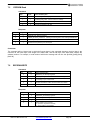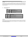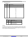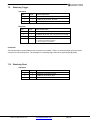
1
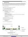
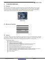
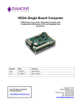
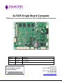
ALTAIR Single Board Computer COM Express Form Factor Intel Atom E-Series SBC with EMX Stackable I/O Expansion Revision Date Comments A.00 12/6/2012 Initial Release A.01 9/3/2015 Minor updates FOR TECHNICAL SUPPORT PLEASE CONTACT: [email protected] Copyright 2015 Diamond Systems Corporation 555 Ellis Street Mountain View, CA 94043 USA Tel 1-650-810-2500 Fax 1-650-810-2525 www.diamondsystems.com CONTENTS Important Safe-Handling Information .....................................................................................................................4 1. Introduction .......................................................................................................................................................5 1.1 Altair SBC Features .......................................................................................................................................6 1.2 Thermal Considerations ................................................................................................................................7 2. Functional Overview .........................................................................................................................................8 2.1 Block Diagram ...............................................................................................................................................8 2.2 Altair Dimensions ...........................................................................................................................................9 2.3 Connector Locations ................................................................................................................................... 10 2.3.1 Connector Summary .......................................................................................................................... 11 2.4 Configuration Jumpers ............................................................................................................................... 12 2.4.1 Configuration Jumper Summary ........................................................................................................ 13 3. Getting Started ............................................................................................................................................... 14 3.1 Introducing the Altair Development Kit ....................................................................................................... 14 3.1.1 Altair Cable Kit ................................................................................................................................... 15 3.2 System Setup ............................................................................................................................................. 16 3.2.1 Keyboard and Mouse ......................................................................................................................... 16 3.2.2 USB Flashdisk Socket ....................................................................................................................... 16 3.2.3 Mass Storage Devices ....................................................................................................................... 16 3.2.4 Connecting Power .............................................................................................................................. 16 3.2.5 Display ............................................................................................................................................... 16 3.2.6 Installing Altair in an Enclosure (optional).......................................................................................... 16 3.3 Booting the System .................................................................................................................................... 17 3.3.1 BIOS Setup ........................................................................................................................................ 17 3.3.2 Operating System Drivers .................................................................................................................. 17 4. Interface Connector Details .......................................................................................................................... 18 4.1 External Battery (J2) ................................................................................................................................... 18 4.2 CAN (J3) ..................................................................................................................................................... 18 4.3 SATA (J4) ................................................................................................................................................... 19 4.4 Ethernet (J5) ............................................................................................................................................... 19 4.5 Serial Ports (J7, J8) .................................................................................................................................... 20 4.6 USB Flashdisk (J9) ..................................................................................................................................... 20 4.7 USB 0-1 (J10) ............................................................................................................................................. 21 4.8 USB 2-3 (J11) ............................................................................................................................................. 21 4.9 Utility Signals (J12) ..................................................................................................................................... 22 4.10 LCD Backlight (J14) .................................................................................................................................... 22 4.11 LCD Panel (LVDS Interface) (J15) ............................................................................................................. 23 4.12 EMX Expansion Bus (J20) .......................................................................................................................... 24 4.13 Power Input (J24) ....................................................................................................................................... 24 4.14 GPIO (J26) .................................................................................................................................................. 25 4.15 PIC Programming (J27) .............................................................................................................................. 25 4.16 PCIe MiniCard (J28) ................................................................................................................................... 25 4.17 Audio (J29) ................................................................................................................................................. 26 4.18 VGA (J30) ................................................................................................................................................... 26 5. Configuration Jumper Details ...................................................................................................................... 27 5.1 Serial Port 1 RS-422/485 Termination (JP1) .............................................................................................. 27 5.2 LCD Panel Power Select – LVDS VSEL (JP2) ........................................................................................... 27 5.3 LCD Backlight Power Select – INV VSEL (JP4)......................................................................................... 28 5.4 LCD Scan Direction & LVDS Map Select (JP5) ......................................................................................... 28 6. BIOS ................................................................................................................................................................ 29 6.1 Entering the BIOS ....................................................................................................................................... 29 6.2 Restoring Default BIOS Settings ................................................................................................................ 29 6.3 Setting the Date and Time .......................................................................................................................... 29 6.4 Boot Priority ................................................................................................................................................ 29 6.5 Chipset ........................................................................................................................................................ 29 6.1 Console Redirection ................................................................................................................................... 29 6.2 Viewing and Modifying the BIOS Settings .................................................................................................. 29 6.3 BIOS Screen Descriptions .......................................................................................................................... 30 7. PIC Microcontroller ........................................................................................................................................ 33 7.1 Are you there .............................................................................................................................................. 34 7.2 Configure DIO Port Command ................................................................................................................... 34 Altair User Manual Rev A.01 www.diamondsystems.com Page 2 7.3 DIO Read .................................................................................................................................................... 35 7.4 DIO Output.................................................................................................................................................. 35 7.5 EEPROM Read........................................................................................................................................... 36 7.6 EEPROM WRITE........................................................................................................................................ 36 7.7 MTBF POWER CYCLE .............................................................................................................................. 37 7.8 Watchdog Timeout Set ............................................................................................................................... 38 7.9 Watchdog Trigger ....................................................................................................................................... 39 7.10 Watchdog Read .......................................................................................................................................... 39 7.11 MTBF Power Data: ..................................................................................................................................... 40 7.12 RTC Read ................................................................................................................................................... 41 7.13 RTC Write ................................................................................................................................................... 42 7.14 Set COM Mode ........................................................................................................................................... 43 7.15 Get COM Mode........................................................................................................................................... 43 7.16 READ ANALOG DATA ............................................................................................................................... 44 7.17 BOARD VOLTAGES .................................................................................................................................. 45 7.18 PWM CONTROL ........................................................................................................................................ 46 7.19 READ DIO CONFIG ................................................................................................................................... 47 7.20 CALENDAR WAKEUP ............................................................................................................................... 47 8. FlashDisk Modules ........................................................................................................................................ 48 8.1 Overview ..................................................................................................................................................... 48 8.2 Models and Capacities ............................................................................................................................... 48 8.3 Features ...................................................................................................................................................... 48 8.4 Flashdisk Installation .................................................................................................................................. 49 8.5 Power Routing ............................................................................................................................................ 49 9. Thermal Pad ................................................................................................................................................... 50 10. Specifications................................................................................................................................................. 51 1.1 Operating System Support ......................................................................................................................... 51 1.2 Mechanical, Electrical, Environmental ........................................................................................................ 51 All trademarks are the property of their respective owners. Altair User Manual Rev A.01 www.diamondsystems.com Page 3 IMPORTANT SAFE-HANDLING INFORMATION WARNING: ESD-Sensitive Electronic Equipment! Observe ESD-safe handling procedures when working with this product. Always use this product in a properly grounded work area and wear appropriate ESD-preventive clothing and/or accessories. Always store this product in ESD-protective packaging when not in use. Safe Handling Precautions Altair contains numerous I/O connectors that connect to sensitive electronic components. This creates many opportunities for accidental damage during handling, installation and connection to other equipment. The list here describes common causes of failure found on boards returned to Diamond Systems for repair. This information is provided as a source of advice to help you prevent damaging your Diamond (or any vendor’s) embedded computer boards. ESD damage – This type of damage is almost impossible to detect, because there is no visual sign of failure or damage. The symptom is that the board simply stops working, because some component becomes defective. Usually the failure can be identified and the chip can be replaced. To prevent ESD damage, always follow proper ESD-prevention practices when handling computer boards. Damage during handling or storage – On some boards we have noticed physical damage from mishandling. A common observation is that a screwdriver slipped while installing the board, causing a gouge in the PCB surface and cutting signal traces or damaging components. Another common observation is damaged board corners, indicating the board was dropped. This may or may not cause damage to the circuitry, depending on what is near the corner. Most of our boards are designed with at least 25 mils clearance between the board edge and any component pad, and ground / power planes are at least 20 mils from the edge to avoid possible shorting from this type of damage. However these design rules are not sufficient to prevent damage in all situations. A third cause of failure is when a metal screwdriver tip slips, or a screw drops onto the board while it is powered on, causing a short between a power pin and a signal pin on a component. This can cause overvoltage / power supply problems described below. To avoid this type of failure, only perform assembly operations when the system is powered off. Sometimes boards are stored in racks with slots that grip the edge of the board. This is a common practice for board manufacturers. However our boards are generally very dense, and if the board has components very close to the board edge, they can be damaged or even knocked off the board when the board tilts back in the rack. Diamond recommends that all our boards be stored only in individual ESD-safe packaging. If multiple boards are stored together, they should be contained in bins with dividers between boards. Do not pile boards on top of each other or cram too many boards into a small location. This can cause damage to connector pins or fragile components. Power supply wired backwards – Our power supplies and boards are not designed to withstand a reverse power supply connection. This will destroy each IC that is connected to the power supply. In this case the board will most likely will be unrepairable and must be replaced. A chip destroyed by reverse power or by excessive power will often have a visible hole on the top or show some deformation on the top surface due to vaporization inside the package. Check twice before applying power! Bent connector pins – This type of problem is often only a cosmetic issue and is easily fixed by bending the pins back to their proper shape one at a time with needle-nose pliers. This situation can occur when pulling a ribbon cable off of a pin header. Note: If the pins are bent too severely, bending them back can cause them to weaken unacceptably or even break, and the connector must be replaced. Altair User Manual Rev A.01 www.diamondsystems.com Page 4 1. INTRODUCTION Altair is a high performance, highly integrated small form factor single board computer in the COM Express form factor. Altair incorporates a wealth of standard PC-style I/O plus on-board digital I/O and accepts EMX add-on I/O modules. An integrated, bottom-mounted heatspreader dissipates heat efficiently to the system enclosure. This configuration leaves the SBC’s top side free for easy access to memory, on-board I/O, and expansion sockets. Key feature highlights include: Compact, low-power, high-performance, stackable SBC Intel Atom E-Series CPU at 1.6GHz (1.3GHz and 600MHz special order options) 1GB or 2GB soldered DDR2 DRAM Comprehensive set of I/O interfaces: - 4 USB 2.0 ports - 1 RS-232/422/485 and 3 RS-232 serial ports - 1 Gigabit Ethernet port - 1 SATA port - LVDS and VGA display interfaces - ALC262 Codec based High Definition Audio with Stereo Line-Out, Stereo Line-In and Microphone - USB keyboard and mouse support - 10 programmable general purpose I/O lines - Watchdog timer Optional on-board USB flashdisk up to 8GB COM Express form factor (125mm x 95mm) System expansion flexibility - EMX stackable I/O - PCIe MiniCard -40°C to +85°C operating temperature Altair’s features are summarized on the next page. Figure 1: Edge View of the Altair SBC Altair User Manual Rev A.01 www.diamondsystems.com Page 5 Altair Models Processor Type Processor Clock SO-DIMM RAM ALT1600-2G-XT Intel Atom E680T CPU 1.6GHz 2GB DDR2 DRAM ALT1600-1G-XT Intel Atom E680T CPU 1.6GHz 1GB DDR2 DRAM ALT1300-2G-XT * Intel Atom E660T CPU 1GHz 2GB DDR2 DRAM ALT1300-1G-XT * Intel Atom E660T CPU 1GHz 1GB DDR2 DRAM ALT600-2G-XT * Intel Atom E620T CPU 600MHz 2GB DDR2 DRAM ALT600-1G-XT * Intel Atom E620T CPU 600MHz 1GB DDR2 DRAM * Special Order Option 1.1 Altair SBC Features Altair is a compact, rugged, single board computer that features the “Tunnel Creek” Atom E-series processors in the COM Express form factor. It provides multiple I/O expansion options by means of the EMX expansion connector. Functions Intel Atom “Tunnel Creek” processors (Queensbay platform), clocked at 1.6GHz standard, 1.3GHz and 600MHz special order options Cooling: Fanless design incorporates heatspreader and conduction cooling to the enclosure Memory: 1GB or 2GB DDR2 memory soldered on board Display options: - LVDS flat panel interface - One on-board SDVO-to-VGA converter to a VGA connector. SDVO-to-DVI converter option also provided. - LVDS backlight power: +5V or +12V jumper selectable 4 USB 2.0 ports on headers (Additionally an USB Hub is implemented to facilitate three ports for the EMX expansion connector and one port for the PCIe MiniCard socket) 4 serial ports; Port 1 supports TX, RX, RTS and CTS with RS-232/422/485 capability and Ports 2, 3, 4 support TX/RX RS-232 only Networking: One Intel 82574IT based Gigabit Ethernet port on pin header, with on-board magnetics Mass storage: - One SATA port - USB flashdisk mounting location supporting up to 8GB Keyboard/Mouse: support for USB ALC262 Codec based High Definition Audio with Stereo Line-Out, Stereo Line-In and Microphone. 10 GPIOs from the PIC Microcontroller 1 CAN port Programmable watchdog timer Expansion buses: EMX stackable I/O; PCIe MiniCard Input power: 5VDC ±5% Power consumption: 15W fully loaded Altair User Manual Rev A.01 www.diamondsystems.com Page 6 Operating temperature: -40°C to +85°C (-40°F to +185°F) COM Express form factor: 125mm x 95mm (4.92” x 3.74”) Weight: 10.8oz (306.2grams) with heatspreader RoHS: Compliant Operating System Support Windows Embedded Standard 7 Windows Embedded CE Linux 2.6.xx 1.2 Thermal Considerations o o All models of Altair are specified for a -40 C to +85 C operating range, the temperature being measured at the outside surface of the heatspreader. Diamond Systems provides a heatspreader attached to the Altair single board computer as a conductive cooled thermal layer. However, this heatspreader by itself does not constitute the complete thermal solution necessary for any specific implementation, but provides a common interface between the single board computer and the customer’s implementation-specific thermal solution. o The outside surface of the Altair heatspreader must be kept at a temperature not to exceed +85 C. If your environment causes the temperature on the outside surface of the heatspreader to exceed this temperature, you are responsible for removing the additional heat from the system through either an additional passive thermal solution or fan solution. Altair User Manual Rev A.01 www.diamondsystems.com Page 7 2. 2.1 FUNCTIONAL OVERVIEW Block Diagram Figure 2 shows Altair’s functional blocks. Figure 2: Altair SBC Functional Block Diagram Altair User Manual Rev A.01 www.diamondsystems.com Page 8 2.2 Altair Dimensions Figure 3 shows the overall dimensions of the Altair SBC measured in thousandths of inches. . Figure 3: Altair Dimensions, thousandths of inches Altair User Manual Rev A.01 www.diamondsystems.com Page 9 2.3 Connector Locations Figure 4 illustrates the position of interface and bus connectors jumpers located on the top side of the Altair SBC, which features EMX stackable I/O and an EMX connector. The connector for the EMX expansion bus is located on the top side of the board. External Battery al b LCD Backlight te y n EMX Expansion Power In LVDS SATA VGA Utility SSD Audio PIC programming header USB1 and 2 Serial1 and 2 USB3 and 4 Ethernet CAN Serial3 and 4 PIC GPIO / Analog / PWM PCIe MiniCard Figure 4: Altair SBC Connector Locations Altair User Manual Rev A.01 www.diamondsystems.com Page 10 2.3.1 Connector Summary The following table summarizes the functions of Altair’s interface, utility, and power connectors. Signal functions relating to all of Altair’s interface connectors are discussed in greater detail in Section 4 of this document. Diamond offers an optional Altair Cable Kit (number C-ALT-KIT), which provides mating cable assemblies for most of Altair’s I/O interface connectors. Connector Function External Battery CAN SATA Ethernet Serial Ports USB Flashdisk USB Ports Utility Signals LCD Backlight LCD (LVDS) Panel EMX I/O Power Input GPIO PIC Programming PCIe MiniCard Audio VGA Altair User Manual Rev A.01 Silkscreen Label J2 J3 J4 J5 J7, J8 J9 J10, J11 J12 J14 J15 J20 J24 J26 J27 J28 J29 J30 www.diamondsystems.com Page 11 2.4 Configuration Jumpers Figure 5 shows the configuration jumper groups that are located on the topside of the Altair SBC. Refer to Section 5 for details on the functions and configuration options associated with each jumper group. LCD Backlight LCD Scan / Map LCD Power Serial Ports Figure 5: Altair SBC Configuration Jumper Groups Altair User Manual Rev A.01 www.diamondsystems.com Page 12 2.4.1 Configuration Jumper Summary The Altair SBC contains jumper blocks for configuring the following features. The board also contains locations for installation of 0-ohm resistors in place of all valid jumper positions for a rugged configuration. The 0-ohm resistors are oriented and labeled in a way that provides easy understanding of their use and easy interpretation of their settings. Altair’s configuration jumpers are listed below. Refer to Section 5 of this document for details regarding the configuration of these jumper groups. Jumper Group Function Silkscreen Label Serial Port 1 RS-422/485 mode differential termination resistor: Enable or Disable Array Size JP1 2X2 JP2 1X3 JP4 1X3 JP5 2X2 (default: Disable) LCD panel supply voltage: 3.3V or 5V (default: 3.3V) LCD backlight power: 5V or 12V (+12V provided through the input power connector) (default: 5V) LCD Panel Scan Direction: Normal Scan or Reverse Scan (default: Normal) LVDS Mapping: Map-A or Map-B (default: Map-A) - Altair User Manual Rev A.01 www.diamondsystems.com Page 13 3. GETTING STARTED First-time Altair users normally receive the product as part of Diamond’s Altair Development Kit, which provides everything needed to ensure rapid application development. This section of the Altair User Manual covers basic hardware setup, power connection, system boot-up, and initial software configuration. After Altair is up and running, refer to the later sections of this manual for the detailed hardware and software reference information needed to adapt the product to specific applications. Important Safe-Handling Information WARNING: ESD-Sensitive Electronic Equipment! Observe ESD-safe handling procedures when working with this product. Always use this product in a properly grounded work area and wear appropriate ESD-preventive clothing and/or accessories. Always store this product in ESD-protective packaging when not in use. Please refer to page 4 of this manual (“Important Safe-Handling Information”) for further details. 3.1 Introducing the Altair Development Kit The Altair Development Kit (DK-ALT-xxx) provides everything required for Altair-based rapid application development. The table on the next page lists the boards, cables, and other items included. The xxx denotes the operating system of choice, either Linux (LNX) or Windows Embedded Standard 7 (WE7). Altair User Manual Rev A.01 www.diamondsystems.com Page 14 Item 3.1.1 Diamond P/N Description 1 ALT1600-1G-XT Altair SBC with 1.6GHz Atom E680T CPU, 1GB SDRAM 2 889061x 8GB USB flashdisk with bootable OS pre-loaded 3 C-ALT-KIT Altair Cable Kit 4 PS-5V-04 5V AC Power Adapter 5 7461611 Altair Quick Start Guide (not shown) 6 671061x DVD with backup image and software files 7 DOC-PKG Diamond Systems Document Package (not shown) Altair Cable Kit The Altair Cable Kit (number C-ALT-KIT) provides convenient access to most of Altair’s I/O features. The kit’s cable assemblies are shown in the photo below, and identified in the table that follows. Description Diamond P/N Connects to… Item Qty 1 1 Gigabit Ethernet cable to RJ45 6981315 J5 2 2 Dual serial cable 6981316 J7 and J8 3 2 Dual USB cable 6981317 J10 and J11 4 1 Utility cable 6981318 J12 5 1 Power input cable 6981321 J24 6 1 Digital I/O cable 6981322 J26 7 1 HD Audio cable 6981323 J29 8 1 VGA cable 6981324 J30 Note: On each interface cable, the end of the cable connector that has a red wire going to it should be oriented toward the end of the board connector that is labeled “pin 1” (typically the pin with a square pad on the PCB). Altair User Manual Rev A.01 www.diamondsystems.com Page 15 3.2 System Setup This section outlines a simple process for preparing Altair for first-time operation using the Altair Development Kit. Additional details regarding Altair’s interface functions and connections may be found in Section 4 of this document (Interface Connector Details). 3.2.1 Keyboard and Mouse Altair supports operation using a USB-based keyboard and mouse devices. Plug the USB keyboard connector and USB mouse cable into the Altair Cable Kit cable number 6981317 and the end of the cable into connector J10 on Altair. 3.2.2 USB Flashdisk Socket Altair provides a location for on-board installation of an optional USB flashdisk on connector J9. Plug the USB flashdisk module in the Development Kit into connector J9 on Altair. Remove the screw from the mounting standoff before installing the flashdisk. Secure the flashdisk to Altair with the screw once the flashdisk is installed. 3.2.3 Mass Storage Devices If desired, connect SATA hard drives to Altair by connecting a SATA cable to SATA connector J4 and then to the SATA drive. Altair can operate with a combination of SATA and CD-ROM drives, and can boot from either of them. Caution! Be sure the PS-5V-04 AC power adapter is disconnected from its AC power source prior to performing the following step. 3.2.4 Connecting Power Connect cable 6981321 to the PS-5V-04 AC power adapter or an ATX power supply. Connect the other end of the 6981321 cable to connector J24 on the Altair SBC. 3.2.5 Display Altair provides interfaces for both LVDS flat panel displays and SDVO output. VGA CRTs can also be used, as the board includes an SDVO to VGA converter. Connect the VGA cable, 6981324, between the VGA connector, J30, and a VGA-compatible display. 3.2.6 Installing Altair in an Enclosure (optional) Install the Altair single board computer in an enclosure that has an appropriate mounting-hole pattern (2.8” square). Altair’s heatspreader has four #6-32 threaded holes on 2.8” centers for mounting. Select four #6-32 threaded screws of the proper length and head type to work with your enclosure. Allow a minimum of 0.25” and maximum of 0.40” screw length for insertion into Altair’s heatspreader. The total screw length will depend on the thickness of your enclosure wall. Altair User Manual Rev A.01 www.diamondsystems.com Page 16 3.3 Booting the System Power-up the VGA video monitor. Then plug the PS-5V-04 AC power adapter to an AC outlet. Altair should begin its boot-up sequence immediately, as evidenced by BIOS messages on the connected VGA display. You can run the BIOS Setup utility and proceed to install an operating system on the boot drive just as you would on a normal desktop PC. 3.3.1 BIOS Setup Altair’s BIOS provides a wide range of configuration options. When you power up Altair for the first time, you should immediately enter the BIOS “Setup” utility in order to adjust BIOS settings to match your system’s peripheral devices and other requirements, and to configure various other hardware and software parameters. Options configurable via Setup typically include: Number and type of mass storage devices Boot device priority Video display type and resolution IDA, SATA, serial, and parallel interface modes and protocols PCI and PnP configuration Power management setup Automatic power-up after LAN connection, RTC alarm, power resumption, etc. System monitoring and security functions 3.3.2 Operating System Drivers Altair will boot and run the operating system from the USB flashdisk. Altair should now be fully operational. If you desire to run a different operating system, depending on the operating system to be installed, it may be necessary to install software drivers for on-board interface controllers. Drivers for Windows Embedded Standard 7, Windows Embedded CE, and Linux 2.6, if required, are included on the Software and Documentation CD that is included in the Altair Development Kit. Altair User Manual Rev A.01 www.diamondsystems.com Page 17 4. INTERFACE CONNECTOR DETAILS This section describes the functions associated with the Altair EMX SBC, EMX bus expansion, utility, I/O interfaces, and power connectors in greater detail. Section 3.1.1 contains a list of ready-to-use interface cables included in Diamond’s Altair Cable Kit. 4.1 External Battery (J2) Altair has provision for an external battery connection via J2, a two-pin connector. A connector and jumper are provided to disable the on-board battery and enable use of an external battery instead. The external battery voltage requirement is 3.3V +/-10%. The jumper also clears the CMOS RAM when it is removed and no external battery is connected. 1 Ground 2 Battery+ Connector type: HIROSE, DF13-2P-1.25DSA(50) 4.2 CAN (J3) The CAN signals from the Intel Topcliff I/O Hub are available at this 1X4 1.25mm connector. 1 2 3 4 CAN_H CAN_L +5V GND Connector type: MOLEX, 532610471 Altair User Manual Rev A.01 www.diamondsystems.com Page 18 4.3 SATA (J4) The SATA connector is an industry-standard right-angle connector. It is mounted flush with the edge of the board so as to plug the SATA cable to an external hard drive. 1 Ground 2 Transmit+ 3 Transmit- 4 Ground 5 Receive- 6 Receive+ 7 Ground Connector type: SAMTEC 4.4 Ethernet (J5) This connector provides access to the board's Gigabit Ethernet port. DA+ 1 2 DB+ DA- 3 4 DB- DC+ 5 6 DD+ DC- 7 8 DD- NC 9 10 NC Connector type: JST, SM10B-ZPDSS-TF Altair User Manual Rev A.01 www.diamondsystems.com Page 19 4.5 Serial Ports (J7, J8) Altair provides four serial ports of which Port 1 supports RS-232/422/485 multiprotocol with the TX, RX, RTS and CTS signals. Ports 2, 3 and 4 support RS-232 only with the TX/RX only as shown in the pinouts below. Protocol RS-422 Full Duplex RS-232 Port# SERIAL 1 SERIAL 2 SERIAL 3 SERIAL 4 RS-485 Half Duplex TX1 KEY RTS1 NC RX2 1 3 5 7 9 2 4 6 8 10 RX1 GND CTS1 NC TX2 TX1+ KEY TX1NC NC 1 3 5 7 9 2 4 6 8 10 RX1+ GND RX1NC NC TX3 KEY NC NC RX4 1 3 5 7 9 2 4 6 8 10 RX3 GND NC NC TX4 NC KEY NC NC NC 1 3 5 7 9 2 4 6 8 10 NC KEY NC NC NC TX1+/RX1+ KEY TX1-/RX1NC NC 1 3 5 7 9 2 4 6 8 10 NC GND NC NC NC NC KEY NC NC NC 1 3 5 7 9 2 4 6 8 10 NC KEY NC NC NC Connector type: JST, SM10B-ZPDSS-TF or equivalent 4.6 USB Flashdisk (J9) This connector is used for the USB on-board flashdisk interface. This is a dedicated USB port. +5V 1 2 NC USB Data- 3 4 NC USB Data+ 5 6 NC USB GND 7 8 NC Key 9 10 NC Connector type: Sullins, NRPN052MAMS-RC Altair User Manual Rev A.01 www.diamondsystems.com Page 20 4.7 USB 0-1 (J10) This connector provides access to two of the board's four USB 2.0 ports, USB0 and USB1. The shield pin is tied to system ground. NC 1 2 Shield USB1 GND 3 4 USB0 GND USB1 Data+ 5 6 USB0 Data+ USB1 Data- 7 8 USB0 Data- USB1 Pwr+ 9 10 USB0 Pwr+ Connector type: JST, SM10B-ZPDSS-TF 4.8 USB 2-3 (J11) This connector provides access to two of the board's four USB 2.0 ports, USB2 and USB3. The shield pin is tied to system ground. NC 1 2 Shield USB3 GND 3 4 USB2 GND USB3 Data+ 5 6 USB2 Data+ USB3 Data- 7 8 USB2 Data- USB3 Pwr+ 9 10 USB2 Pwr+ Connector type: JST, SM10B-ZPDSS-TF Altair User Manual Rev A.01 www.diamondsystems.com Page 21 4.9 Utility Signals (J12) This connector provides utility signals for Altair as follows. 1 2 3 4 5 6 7 8 9 USB_DEV_PWR USB_DEV_D_N USB_DEV_D_P GND SPKR +5V /PWRBTN GND /RESET Connector type: MOLEX, 532610971 4.10 LCD Backlight (J14) This connector provides the backlight power and control for the optional LCD panel. Note: If needed, +12V must be provided on the input power connector. 1 Power +5V/+12V, jumper selectable, default +5V 2 Power (same as pin 1) 3 Ground 4 Ground 5 Enable (GPIO output), 0 = off, open circuit = on 6 Brightness, 0-5VDC variable; 0V = max, 5V = min (PWM control implemented) The brightness control for the LCD backlight has a weak pull-down resistor to ensure maximum brightness when it is not connected externally. Brightness may be controlled by a GPIO pin on the CPU or embedded microcontroller or by pin 6 on this connector. A jumper selects the source of the brightness signal to this pin. Connector type: Molex 53261-0671 or equivalent Mating connector: Socket: Molex 51021-0600 or equivalent Terminals: Molex 50058 / 50079 series or equivalent Altair User Manual Rev A.01 www.diamondsystems.com Page 22 4.11 LCD Panel (LVDS Interface) (J15) This connector is mounted on the top side of Altair. It provides connection to an LVDS LCD display. The LCD panel power is jumper selectable for 3.3V (default) or 5V. 1 Ground / D3+, depending on video chip 2 Ground / D3-, depending on video chip 3 Scan Direction (High = Reverse Scan, Low/open = Normal Scan) 4 LVDS Mapping (High = Map-B, Low = Map-A) 5 Signal Ground 6 Pixel Clock + 7 Pixel Clock - 8 Signal Ground 9 D2+ 10 D2- 11 Signal Ground 12 D1+ 13 D1- 14 Signal Ground 15 D0+ 16 D0- 17 Power Ground 18 Power Ground 19 Vcc 3.3V / 5V (jumper configured) 20 Vcc 3.3V / 5V (jumper configured) Connector type: JAE part no. FI-SE20P-HFE or equivalent Cable-mount socket: JAE part no. FI-SE20S-2-L or equivalent Altair User Manual Rev A.01 www.diamondsystems.com Page 23 4.12 EMX Expansion Bus (J20) This connector is implemented to facilitate I/O expansion modules to be plugged onto the Altair SBC. Gnd 1 2 Gnd USB2+ 51 52 SATA-R+ USB2- 53 54 SATA-R- PE4T+ 3 4 PE1T+ PE4T- 5 6 PE1T- +3.3V 55 56 +3.3V Gnd 7 8 Gnd Reserved 57 58 Reserved Reserved 59 60 Reserved PE3T+ 9 10 PE2T+ PE3T- 11 12 PE2T- Gnd 13 14 Gnd PE4R+ 15 16 PE1R+ PE4R- 17 18 PE1R- Gnd 19 20 Gnd PE3R+ 21 22 PE2R+ PE3R- 23 24 PE2R- Gnd 25 26 Gnd PE4C+ 27 28 PE1C+ PE4C- 29 30 Gnd 31 32 PE3C+ 33 34 +5V 61 62 +5V Reserved 63 64 Reserved Reserved 65 66 Reserved +5V 67 68 +5V Reserved 69 70 SMB-Clk Reserved 71 72 SMB-Data +5V 73 74 SMB-Alert- Reserved 75 76 +5V Reserved 77 78 +5V PE1C- +5VSB 79 80 LPC-AD0 Gnd +5VSB 81 82 LPC-AD1 PE2C+ VBat 83 84 LPC-AD2 Wake- 85 86 LPC-AD3 PE3C- 35 36 PE2C- +3.3V 37 38 +3.3V IOControl1 87 88 LPC-FRAME- PE4clkreq- 39 40 PE1clkreq- IOControl2 89 90 LPC-SERIRQ- USB-OC- 91 92 LPC-DRQ PE3clkreq- 41 42 PE2clkreq- +3.3V 43 44 +3.3V USB1+ 45 46 SATA-T+ USB1- 47 48 SATA-T- +3.3V 49 50 +3.3V IOReady 93 94 LPC-CLK1 Device Reset- 95 96 LPC-CLK2 Host Reset- 97 98 Gnd Gnd 99 100 Gnd Connector type: Molex, 52901-1074 4.13 Power Input (J24) The power signals on this connector come from a connector leading to the output from a DC/DC power supply installed in the system. Ground Ground Ground Ground Ground NC 1 3 5 7 9 11 2 4 6 8 10 12 +5VDC +5VDC +5VDC +5VDC +12VDC NC Connector type: JST, SM12B-ZPDSS-TF Altair User Manual Rev A.01 www.diamondsystems.com Page 24 4.14 GPIO (J26) This connector provides the digital IO, PWM and analog signals from the PIC microcontroller. GPIO1 - Digital GPIO3 – Digital GPIO5 – Digital GPIO7 – Digital GPIO9 - Digital PWM – B PWM – D DGND ANALOG IN – 1 ANALOG IN – 3 1 3 5 7 9 11 13 15 17 19 2 4 6 8 10 12 14 16 18 20 GPIO0 - Digital GPIO2 - Digital GPIO4 - Digital GPIO6 - Digital GPIO8 - Digital PWM – A PWM – C AGND ANALOG IN – 0 ANALOG IN – 2 Connector type: JST, SM20B-ZPDSS-TF 4.15 PIC Programming (J27) This header is used to program (ICSP) the on-board PIC Microcontroller. 1 2 3 4 5 6 MCLR +3V3 GND PGD PGC NC Connector type: Aptos, LTY-06S2-VB-040/028-FG 4.16 PCIe MiniCard (J28) The PCIe MiniCard socket provides the facility to plug-in third party Mini-PCIe cards such as WiFi, Bluetooth, etc. WAKE# COEX1 COEX2 CLKREQ# GND1 REFCLKREFCLK+ GND2 RSVD(UIM_C8) RSVD(UIM_C4) 1 3 5 7 9 11 13 15 2 4 6 8 10 12 14 16 KEY 17 18 19 20 +3.3VAUX_3 GND9 +1.5V_1 UIM_PWR UIM_DATA UIM_CLK UIM_RESET UIM_VPP GND10 W_DISABLE# GND3 PERN0 PERP0 GND4 GND5 PETN0 PETP0 GND6 GND7 +3.3VAUX_1 +3.3VAUX_2 21 23 25 27 29 31 33 35 37 39 41 22 24 26 28 30 32 34 36 38 40 42 PERST# +3.3VAUX_4 GND11 +1.5V_2 SMB_CLK SMB_DATA GND12 USB_DUSB_D+ GND13 LED_WWAN# GND8 RSVD1 RSVD2 RSVD3 RSVD4 43 45 47 49 51 44 46 48 50 52 Connector type: JAE, MM60-52B1-E1-R650 Altair User Manual Rev A.01 www.diamondsystems.com Page 25 LED_WLAN# LED_WPAN# +1.5V_3 GND14 +3.3VAUX_5 4.17 Audio (J29) The Audio connector has the Stereo Line-In, Stereo Line-Out and Mono Microphone signals from the ALC262 HD-Audio Codec. External speakers, headphones and a microphone can be interfaced to this connector. LineOut – L GND_AUDIO LineIn – L GND_AUDIO MIC IN 1 3 5 7 9 2 4 6 8 10 LineOut – R GND_AUDIO LineIn – R GND_AUDIO GND_AUDIO Connector type: JST, SM10B-ZPDSS-TF 4.18 VGA (J30) The VGA connector has the VGA signals connected to it from the SDVO to VGA converter. A VGA monitor can be connected to this. RED GREEN BLUE GND VSYNC DDC DATA NC 1 3 5 7 9 11 13 2 4 6 8 10 12 14 VGA GND VGA GND VGA GND HSYNC GND DDC CLK GND Connector type: JST, SM14B-ZPDSS-TF Altair User Manual Rev A.01 www.diamondsystems.com Page 26 5. CONFIGURATION JUMPER DETAILS This section explains the use of several jumper options on the Altair Baseboard. The board contains jumper blocks for configuring the following features. The board also contains locations for installation of 0-ohm resistors in place of all valid jumper positions for a rugged configuration. The 0-ohm resistors are oriented and labeled in a way that provides easy understanding of their use and easy interpretation of their settings. Jumper Group Function Silkscreen Label Reference Array Size Serial Port 1 RS-422/485 mode differential termination resistor; Enable or Disable LCD panel supply voltage: 3.3V or 5V LCD backlight power: 5V or 12V (+12V provided through the input power connector) JP1 2X2 LVDS VSEL JP2 1X3 INV VSEL JP4 1X3 JP5 2X2 LCD Panel Scan Direction; Normal Scan or Reverse Scan LCD Panel Map; Map-A or Map-B 5.1 5.2 Serial Port 1 RS-422/485 Termination (JP1) Setting Termination Enable/Disable Protocol Open Termination Disable (default) RS-233 1–2 RS-422 Termination Enable RS-422 3–4 RS-485 Termination Enable RS-485 LCD Panel Power Select – LVDS VSEL (JP2) This jumper group must be configured according to input voltage required by the type of LCD panel that will be attached to Altair’s LCD panel interface connector. Altair User Manual Rev A.01 Setting LCD Panel Voltage 1-2 +5V 2-3 +3.3V (default) www.diamondsystems.com Page 27 5.3 LCD Backlight Power Select – INV VSEL (JP4) This jumper group selects the LCD backlight inverter DC power voltage. 5.4 Setting LCD Backlight Power 1–2 +5V (default) 2–3 +12V LCD Scan Direction & LVDS Map Select (JP5) This jumper group controls the LCD panel scan direction and frame rate control. These settings depend on the LCD panel manufacturer. Every panel has its own setting logic. Setting LCD Scan Direction 1-2 Normal Scan Direction (default) Open Reverse Scan Direction Setting LCD Map 3–4 Map – A (default) Open Map – B Altair User Manual Rev A.01 www.diamondsystems.com Page 28 6. BIOS Altair’s BIOS provides access to many valuable features. These instructions show how to enter the BIOS, set up features, and restore the BIOS to its default settings. 6.1 Entering the BIOS The BIOS may be entered during startup by pressing the DEL/F2 key on an attached keyboard. Press the key repeatedly right after power-on or reset until the BIOS screen appears. After a certain amount of time during startup, the BIOS will ignore the DEL or F2 key. If you wait too long and the system does not respond, simply reset the system (or power down) and try again. 6.2 Restoring Default BIOS Settings In order to load the default BIOS settings, enter the BIOS settings and select Save and Exit menu. Then select Restore Defaults, and save/exit. This will restore the BIOS to the default state. 6.3 Setting the Date and Time The date and time are set in the BIOS. Select Main menu, then enter the date and time at the bottom of the screen. This screen also displays the CPU speed and memory capacity of the board. 6.4 Boot Priority To select Boot devices and set their priority, go to the Boot menu. Set the boot option priorities on this page. 6.5 Chipset The chipset menu is provided to define and change the North / South Bridge options such as Graphic Adapter Modes, flat panel type (default is 800x600) etc., The Chipset menu also has various other options such as GPIO settings, enabling/disabling the audio controllers, PCIe root port configurations. 6.1 Console Redirection In the Advanced menu, the user can select any of the serial ports for console redirection with different speeds ranging from 115200bps to 9600bps. Select the Serial Port Console Redirection sub menu. When set to Enabled, the console re-direction is activated on COM1 by default at 115200,n,8,1 communication settings. The remote access configuration can be enabled on any of the four COM ports. Baud rates supported are 115200 (default when enabled), 57600, 38400, 19200 and 9600. 6.2 Viewing and Modifying the BIOS Settings During board startup, press function key <F2> to enter BIOS setup mode. The main page displays the following menu options: Main Advanced GPIO Wake Configuration Chipset Boot Security Save & Exit Select the menu option to view or modify the BIOS settings for the desired configuration area. The screens displayed for each area are described, below. Altair User Manual Rev A.01 www.diamondsystems.com Page 29 The following keyboard controls are available on any page for navigating the screen, as displayed at the bottom of each page. Key F1 Esc up-/down-arrow left-/right-arrow plus/minus symbols (+/-) Enter F9 F10 Function Help Exit current screen Select setup item Select menu item Change values Execute command Save default values Save changes and exit BIOS setup mode At any time, select Save & Exit to exit BIOS setup mode. Use the up/down arrow keys, followed by carriage return, to apply one of the exit actions. 6.3 BIOS Screen Descriptions This section describes the screen displays for each BIOS setup area. The data in the fields are examples only and may be different depending on future product releases from Diamond Systems or the user’s configuration. Sub-menus are prefixed with a . Main BIOS Information BIOS Vendor American Megatrends Product Name Altair Motherboard Manufacturer Diamond Systems MRC Version 01.00 Total Memory 1024 MB (DDR2) Platform Information System Language [English] System Date [Tue 11/13/2012] System Time [12:37:18] Access Level Administrator Altair User Manual Rev A.01 www.diamondsystems.com Page 30 Advanced Legacy OpROM Support Launch PXE OpROM [Disabled] Launch Storage OpROM [Enabled] PCI Subsystem Settings ACPI Settings Windows CE CPU Configuration Wake On Lan Configuration Thermal Configuration USB Configuration SIO Configuration Hardware Health Monitor Serial Port Console Redirection GPIO Wake Configuration GPIO Wake Configuration Wake on GPIO0 [Disabled] Wake on GPIO1 [Disabled] Chipset North Bridge Chipset Configuration South Bridge Chipset Configuration IOH Configuration Boot Boot Configuration Quiet Boot [Disabled] Fast Boot [Disabled] Setup Prompt Timeout 1 Bootup NumLock State [On] CSM16 Module Version 07.65 GateA20 Active [Upon Request] Option ROM Messages [Force BIOS] Interrupt 19 Capture [Disabled] Boot Option Priorities Boot Option #1 [ PMAP] Boot Option #2 [Built-in EFI Shell] Boot Option #3 [UEFI: PMAP] Hard Drive BBS Priorities Altair User Manual Rev A.01 www.diamondsystems.com Page 31 Security Administrator Password User Password Save & Exit Boot to Windows CE Save Changes and Exit Discard Changes and Exit Save Changes and Reset Discard Changes and Reset Save Options Save Changes Discard Changes Restore Defaults Save as User Defaults Restore as User Defaults Boot Override Built-in EFI Shell PMAP UEFI: PMAP Altair User Manual Rev A.01 www.diamondsystems.com Page 32 7. PIC MICROCONTROLLER The Altair SBC contains a PIC microcontroller that is used to provide various functions including serial port configuration, general purpose I/O lines, A/D lines, pulse width modulators, generate wake events, and others. This section describes the command sets that can be used to communicate with the PIC controller. The list below describes the constants that have been used in this section. MESSAGE_SIG COMMAND_AREYOU COMMAND_WRITE_EPROM COMMAND_READ_EPROM COMMAND_CONFIG_DIOPORT COMMAND_DIO_OUTPUT COMMAND_DIO_READ COMMAND_ANALOG_READ COMMAND_CONFIG_PWM COMMAND_WATCHDOG_SET COMMAND_WATCHDOG_READ COMMAND_WATCHDOG_TRIGGER COMMAND_CALENDAR_WAKEUP COMMAND_MTBF_DATA COMMAND_MTBF_POWER COMMAND_RTC_READ COMMAND_RTC_WRITE COMMAND_SET_COM_MODE COMMAND_GET_COM_MODE COMMAND_BOARD_VOLTAGE COMMAND_CONFIG_READ_DIOPORT COMMAND_RECEIVER_AREYOUTHERE COMMAND_RECEIVER_EPROMDATA COMMAND_RECEIVER_DIODATA COMMAND_RECEIVER_ANALOG_DATA COMMAND_RECEIVER_WATCHDOG_SETTINGS COMMAND_RECEIVER_ACK COMMAND_RECEIVER_MTBF_DATA COMMAND_RECEIVER_MTBF_POWER COMMAND_RECEIVER_RTC_DATA COMMAND_RECEIVER_GET_COM_MODE COMMAND_RECEIVER_BOARD_VOLTAGE COMMAND_RECEIVER_CONFIG_READ_DIOPORT Altair User Manual Rev A.01 www.diamondsystems.com 0x3232 0x01 0x03 0x05 0x07 0x09 0x0B 0x0D 0x0F 0x17 0x19 0x1B 0x1D 0x1F 0x21 0x23 0x25 0x27 0x29 0X2B 0x2F 0x02 0x04 0x0C 0x0E 0x1A 0x1C 0x1E 0x20 0x22 0x24 0X26 0x2A Page 33 7.1 Are you there Command Description: Byte Length Value and Description 0 2 MESSAGE_SIG: Message signature 2 1 COMMAND_AREYOU: Command id for the “are you there command” 3 1 0: No extra data sent Response: Byte Length Value and Description 0 2 MESSAGE_SIG: Message signature 2 1 COMMAND_RECEIVER_AREYOUTHERE 3 1 Specifies the length of the buffer as 1 byte long 4 1 Version Number of the firmware Comments: This command is used to retrieve the firmware version running on the target system. If the firmware version is 2, then the message sent is 3232010 and the received message is 3232020102. 7.2 Configure DIO Port Command Command: Byte Length Value and Description 0 2 MESSAGE_SIG: Message signature 2 1 COMMAND_CONFIG_DIOPORT: Command id for the message 3 1 1 4 1 Pin number Response: Byte Length Value and Description 0 2 MESSAGE_SIG: Message signature 2 1 COMMAND_RECEIVER_ACK: Command id for the message 3 1 1 4 1 Return status for the command 0: Operation completed successfully 1: Some problem in the operation Comments: This command is used to toggle the configuration direction of a digital IO pin. The value of the pin number must be between 0 and 9. Altair User Manual Rev A.01 www.diamondsystems.com Page 34 7.3 DIO Read Command: Byte Length Value and Description 0 2 MESSAGE_SIG: Message signature 2 1 COMMAND_DIO_READ: Command id for the message 3 1 0 Response: Byte Length Value and Description 0 2 MESSAGE_SIG: Message signature 2 1 COMMAND_RECEIVER_DIODATA: Command id for the message 3 1 2: Indicating 2 bytes data 4 2 The state of all the DIO pins from 0 to 9 Comments: This command reads the data from all the pins starting from 0 and ending with 9. The response contains the data for all the pins encoded in 2 bytes of data. Bit 0 to 7 for the first data byte will contain the data for DIO 0 to 7 and bit 0 and 1 of second data byte will contain the data for DIO 8 and 9. 7.4 DIO Output Command: Byte Length Value and Description 0 2 MESSAGE_SIG: Message signature 2 1 COMMAND_DIO_OUTPUT: Command id for the message 3 1 1 4 1 Pin number Response: Byte Length Value and Description 0 2 MESSAGE_SIG: Message signature 2 1 COMMAND_RECEIVER_ACK: Command id for the message 3 1 1 4 1 Return status for the command 0: Operation completed successfully 1: Some problem in the operation Comments: This command toggles the current state of the selected pin from LOW to HIGH, or HIGH to LOW. The response is an acknowledgement for the successful completion of the command. Altair User Manual Rev A.01 www.diamondsystems.com Page 35 7.5 EEPROM Read Command: Byte Length Value and Description 0 2 MESSAGE_SIG: Message signature 2 1 COMMAND_READ_EPROM: Command id of the message 3 1 2: Indicating the 2 byte address to be read from the EEPROM 4 2 Contains the address to be read Response: Byte Length Value and Description 0 2 MESSAGE_SIG: Message signature 2 1 COMMAND_RECEIVER_EPROMDATA: Indicating the following data is from reading EEPROM data 3 1 1: Indicating one byte of data to be read 4 1 The data that is requested by the read request Comments: The command will be 6 bytes long in which the first two bytes is the command signature, the third byte is the command id, the fourth byte is the length of the data buffer, and the fifth byte is the data which contains the address location. For example, to read location 0x0130 the message will look like this [0x3232] [0x05] [0x02] [0x0130]. 7.6 EEPROM WRITE Command: Byte Length Value and Description 0 2 MESSAGE_SIG: Message signature 2 1 COMMAND_WRITE_EPROM: Command id for the message 3 1 3: Indicating 3 bytes of data is sent 4 2 Contains the address location where the data is to be written 6 1 The 1 byte of data that is to be written to the EEPROM section Response: Byte Length Value and Description 0 2 MESSAGE_SIG: Message signature 2 1 COMMAND_RECEIVER_ACK: Command id for the message 3 1 1 4 1 Return status for the command 0: Operation completed successfully 1: Some problem in the operation Altair User Manual Rev A.01 www.diamondsystems.com Page 36 Comments: This command is used to write data to the EEPROM. The first four bytes will contain the data, just like other commands, only the command id and length will be different. The firmware has to know the address of the memory location where data will be written and the data itself. Hence for specifying the address, two bytes are used. One byte for the data is filled in the data section. For writing multiple bytes or bulk data, this command can be issued multiple times. 7.7 MTBF POWER CYCLE Command: Byte Length Value and Description 0 2 MESSAGE_SIG: Message signature 2 1 COMMAND_MTBF_POWER: Command id 3 1 0: Indicating no data is sent Response: Byte Length Value and Description 0 2 MESSAGE_SIG: Message signature 2 1 COMMAND_RECEIVER_MTBF_POWER: Indicating the command to process 3 1 4: Indicating 4 bytes of data to follow 4 4 4 byte long counter to be returned as response to this command Comments: MTBF data gives the count of the number of power restarts that have occurred in the system. The first two bytes contains the same meaning as the previous commands. The third byte contains the command id for the operation. This command does not need any parameter; hence its data length is zero. To retrieve MTBF data, the message will look like [0x3232] [0x1F] [0x00]. Altair User Manual Rev A.01 www.diamondsystems.com Page 37 7.8 Watchdog Timeout Set Command: Byte Length Value and Description 0 2 MESSAGE_SIG: Message signature 2 1 COMMAND_WATCHDOG_SET: Sets the watchdog timeout to predefined values 3 1 1: Indicating 1 byte of data follows 4 1 The time value set depending on the following set of values: Value 0: Time interval 1 sec 1: 2: 2 sec 4 sec 3: 4: 8 sec 16 sec 5: 32 sec 6: 1 min. 7: 8: 2 min. 4 min. 9: 9 min. 10: 17 min. 11: 35 min. 12: 70 min. 13: Disable Response: Byte Length Value and Description 0 2 MESSAGE_SIG: Message signature 2 1 COMMAND_RECEIVER_ACK: Command id for the message 3 1 1 4 1 Return status for the command 0: Operation completed successfully 1: Some problem in the operation Comments: This command is used to set the time out value for the microcontroller. This feature is useful to reset the microcontroller from a non-responsive state, or when the master system has lost connectivity with the firmware. The first four bytes are organized just like the previous messages and interpreted in the same way in the firmware. The fifth byte contains data specifying the timeout length. For example, to set a 16 second time out value, the message will looks like [0x3232] [0x17] [0x01] [0x04]. Altair User Manual Rev A.01 www.diamondsystems.com Page 38 7.9 Watchdog Trigger Command: Byte Length Value and Description 0 2 MESSAGE_SIG: Message signature 2 1 COMMAND_WATCHDOG_TRIGGER 3 1 0: Indicating no data is sent Response: Byte Length Value and Description 0 2 MESSAGE_SIG: Message signature 2 1 COMMAND_RECEIVER_ACK: Command id for the message 3 1 1 4 1 Return status for the command 0: Operation completed successfully 1: Some problem in the operation Comments: The first three bytes contains data just like the previous commands. There is no extra data required to execute the command, so the fourth byte is 0. The message for a watchdog trigger will look like [0x3232] [0x1B] [0x00]. 7.10 Watchdog Read Command: Byte Length Value and Description 0 2 MESSAGE_SIG: Message signature 2 1 COMMAND_WATCHDOG_READ 3 1 1: Indicating 1 byte of data to be read Altair User Manual Rev A.01 www.diamondsystems.com Page 39 Response: Byte Length Value and Description 0 2 MESSAGE_SIG: Message signature 2 1 COMMAND_RECEIVER_WATCHDOG_SETTINGS: Response ID 3 1 0: Indicating no data is sent 4 1 The time value set depending on the following set of values: Value Time interval 0: 1 sec 1: 2: 2 sec 4 sec 3: 4: 8 sec 16 sec 5: 32 sec 6: 1 min. 7: 8: 2 min. 4 min. 9: 9 min. 10: 17 min. 11: 35 min. 12: 70 min. 13: Disable. Comments: The command returns an integer as its response, which represents a timeout value depending on the value-time interval chart given above. 7.11 MTBF Power Data: Command: Byte Length Value and Description 0 2 MESSAGE_SIG: Message signature 2 1 COMMAND_MTBF_DATA: Indicating the command to process 3 1 0: Indicating no data is sent Response: Byte Length Value and Description 0 2 MESSAGE_SIG: Message signature 2 1 COMMAND_RECEIVER_MTBF_DATA: Indicating the command to process 3 1 4: Indicating 4 bytes of data Comments: This command is similar to the watchdog timeout read command described earlier. It is also 4 bytes long. Only the command id is different. The response of this command returns the boot up time in seconds. Altair User Manual Rev A.01 www.diamondsystems.com Page 40 7.12 RTC Read Command: Byte Length Value and Description 0 2 MESSAGE_SIG: Message signature 2 1 COMMAND_RTC_READ 3 1 0: Indicating no data is sent Response: Byte Length Value and Description 0 2 MESSAGE_SIG: Message signature 2 1 COMMAND_RECEIVER_RTC_DATA: Indicating the command to process 3 1 7: Specifying 7 bytes following 4 1 0 – 99 specifying the year’s last two digits 5 1 1 – 12 specifying Month: 1 for January, 3 for March, 11 for November, and so on 6 1 1 – 31 Date 7 1 1 – 7 Day of week. 1 for Sunday, 3 for Tuesday, 7 for Saturday, and so on 8 1 0 – 23 Hours 9 1 0 – 59 Minutes 10 1 0 – 59 Seconds Comments: This command reads the RTC timer on the microcontroller. Before reading the data, the RTC must be configured with some starting time or else it will give incorrect data. The command structure and description is similar to the watch dog read command or the MTBF power data retrieval command. The command looks like [3232] [19] [00]. Altair User Manual Rev A.01 www.diamondsystems.com Page 41 7.13 RTC Write Command: Byte Length Value and Description 0 2 MESSAGE_SIG: Message signature 2 1 COMMAND_RTC_WRITE 3 1 7: Specifying 7 bytes following this 4 1 0 – 99 specifying the year’s last two digits 5 1 1 – 12 specifying Month: 1 for January, 3 for March, 11 for November, and so on 6 1 1 – 31 Date 7 1 1 – 7 Day of week. 1 for Sunday, 3 for Tuesday, 7 for Saturday, and so on 8 1 0 – 23 Hours 9 1 0 – 59 Minutes 10 1 0 – 59 Seconds Response: Byte Length Value and Description 0 2 MESSAGE_SIG: Message signature 2 1 COMMAND_RECEIVER_ACK: Command id for the message 3 1 1 4 1 Return status for the command 0: Operation completed successfully 1: Some problem in the operation Comments: This command is always ten bytes long. The first four bytes contain information just like other commands. The next seven bytes of information contain data regarding date information as described in the table above. This command configures and starts the RTC module in the firmware. For example to set 29th Feb 2012 5:00:17 PM (Wednesday is day of the week), the command is [0x3232] [0x25] [0x07] [12] [02] [04] [17] [00] [17]. While reading the RTC data, the time information will appear in this format. Altair User Manual Rev A.01 www.diamondsystems.com Page 42 7.14 Set COM Mode Command: Byte Length Value and Description 0 2 MESSAGE_SIG: Message signature 2 1 COMMAND_SET_COM_MODE 3 1 1: Indicating 1 more byte to be read 4 1 1: Indicates RS-232 protocol to be used 2: Indicates RS-485 protocol to be used 3: SPI (Serial Peripheral Interface) protocol to be used Response: Byte Length Value and Description 0 2 MESSAGE_SIG: Message signature 2 1 COMMAND_RECEIVER_ACK: Command id for the message 3 1 1 4 1 Return status for the command 0: Operation completed successfully 1: Some problem in the operations Comments: This command is used to specify what protocol is used by the firmware. This won’t be immediately reflected in the firmware; the protocol will be updated after the device is reset. The default protocol is set as SPI communication (The host windows application is uses the SPI protocol). To set the protocol to RS-232, the message looks like [0x3232] [0x27] [0x01] [0x01]. 7.15 Get COM Mode Command: Byte Length Value and Description 0 2 MESSAGE_SIG: Message signature 2 1 COMMAND_GET_COM_MODE 3 1 0: Indicating no data is sent Response: Byte Length Value and Description 0 2 MESSAGE_SIG: Message signature 2 1 COMMAND_RECEIVER_GET_COM_MODE: Indicating the command to process 3 1 1: Indicating 1 byte of data to be read 4 1 1: Indicates RS-232 protocol to be used 2: Indicates RS-485 protocol to be used 3: SPI (Serial Peripheral Interface) protocol to be used Comments: This command is used to retrieve the protocol used for sending data, or getting data from firmware. The default communication mode is the SPI. The firmware will use the last used protocol (the protocol used for before the last rest) when initializing the firmware Altair User Manual Rev A.01 www.diamondsystems.com Page 43 7.16 READ ANALOG DATA Command: Byte Length Value and Description 0 2 MESSAGE_SIG: Message signature 2 1 COMMAND_ANALOG_READ: Command ID 3 1 0: Indicating no data Response: Byte Length Value and Description 0 2 MESSAGE_SIG: Message signature 2 1 COMMAND_RECEIVER_ANALOG_DATA: Response ID 3 1 8: Indicating 8 bytes of data 4 8 8 bytes of data buffer containing the analog values for channels 0 to 3 Comments: This command retrieves the analog voltage values of channels 0 to 3. The response consists of eight bytes of data which contain the analog voltage for channels 0 to 3 in hex. The data consists of the following values: 1st byte: Lower byte of the voltage value of channel 0 2nd byte: Higher byte of the voltage value of channel 0 3rd byte: Lower byte of the voltage value of channel 1 4th byte: Higher byte of the voltage value of channel 1 5th byte: Lower byte of the voltage value of channel 2 6th byte: Higher byte of the voltage value of channel 2 7th byte: Lower byte of the voltage value of channel 3 8th byte: Higher byte of the voltage value of channel 3 Altair User Manual Rev A.01 www.diamondsystems.com Page 44 7.17 BOARD VOLTAGES Command: Byte Length Value and Description 0 2 MESSAGE_SIG: Message signature 2 1 COMMAND_BOARD_VOLTAGE: Command ID 3 1 0: Indicating no data Response: Byte Length Value and Description 0 2 MESSAGE_SIG: Message signature 2 1 COMMAND_RECEIVER_BOARD_VOLTAGE: Command ID 3 1 10: Indicating 10 bytes of data Comments: This command retrieves the analog voltage values of channels 6 to 10. The response consists of eight bytes of data which contain the analog voltage for channels 6 to 10 in hex. The data consists of the following values: 1st byte: Lower byte of the voltage value of channel 6 2nd byte: Higher byte of the voltage value of channel 6 3rd byte: Lower byte of the voltage value of channel 7 4th byte: Higher byte of the voltage value of channel 7 5th byte: Lower byte of the voltage value of channel 8 6th byte: Higher byte of the voltage value of channel 8 7th byte: Lower byte of the voltage value of channel 9 8th byte: Higher byte of the voltage value of channel 9 9th byte: Lower byte of the voltage value of channel 10 10th byte: Higher byte of the voltage value of channel 10 Altair User Manual Rev A.01 www.diamondsystems.com Page 45 7.18 PWM CONTROL Command: Byte Length Value and Description 0 2 MESSAGE_SIG: Message signature 2 1 COMMAND_CONFIG_PWM: Command ID 3 1 4: Indicating 4 bytes of data 4 4 4 bytes of data: channel number, 2 bytes of frequency, duty cycle percentage between 0 to 100 Response: Byte Length Value and Description 0 2 MESSAGE_SIG: Message signature 2 1 COMMAND_RECEIVER_ACK: Command id for the message 3 1 1 4 1 Return status for the command 0: Operation completed successfully 1 or non-zero: Some problem in the operations Comments: This command enables PWM channels to generate PWM signals of certain frequency and duty cycle. The output pins for different channels are as follows: Channel #1: P1A/RC2 pin Channel #2: P1B/RE6 pin Channel #3: P1C/RE5 pin Channel #4: P1D/REG4 pin The response is a status message for successful completion of the command. Altair User Manual Rev A.01 www.diamondsystems.com Page 46 7.19 READ DIO CONFIG Command: Byte Length Value and Description 0 2 MESSAGE_SIG: Message signature 2 1 COMMAND_CONFIG_READ_DIOPORT: Command ID 3 1 0: Indicating no data Response: Byte Length Value and Description 0 2 MESSAGE_SIG: Message signature 2 1 COMMAND_RECEIVER_CONFIG_READ_DIOPORT: Command ID 3 1 2: Indicating 2 bytes of data Comments: This command reads the configuration direction for all the pins starting from pin 0 and going to pin 9. The response contains the data for all the pins encoded in 2 bytes of data. Bit 0 to 7 for the first data byte contains the data for DIO 0 to 7, and bit 0 and 1 of second data byte contains the data for DIO 8 and 9. 7.20 CALENDAR WAKEUP Command: Byte Length Value and Description 0 2 MESSAGE_SIG: Message signature 2 1 COMMAND_CALENDAR_WAKEUP: Command ID 3 1 6: Indicating 6 bytes of data 4 6 6 bytes of data containing hour, minute, second, day, month and day of week respectively Response: Byte Length Value and Description 0 2 MESSAGE_SIG: Message signature 2 1 COMMAND_RECEIVER_ACK: Command id for the message 3 1 1 4 1 Return status for the command 0: Operation completed successfully 1 or non-zero: Some problem in the operations Comments: This command configures the RTC module to generate an alarm on the date and time set in the six bytes of data in the command. An alarm pulse is generated at pin RG4 at the specified time and date. The response is a status response signaling successful completion of command processing. Altair User Manual Rev A.01 www.diamondsystems.com Page 47 8. 8.1 FLASHDISK MODULES Overview Altair is designed to accommodate an optional wide-temperature solid-state USB flashdisk module for rugged mass storage in place of a notebook hard drive or commercial flashdisk. This module contains 1GB to 8GB of solid-state non-volatile memory that operates like any USB hard disk drive without requiring additional driver software support. It features automatic wear leveling and 1,000,000 write cycles minimum. USB Flashdisk 8.2 8.3 Models and Capacities Model Capacity FDU-1G-XT 1GB FDU-2G-XT 2GB FDU-4G-XT 4GB FDU-8G-XT 8GB Features The flashdisk module works just like a USB disk drive and requires no drivers. It provides high-speed nonvolatile mass storage in capacities of 1GB to 8GB. The flashdisk mounts on connector J9 and is held in place with a spacer and screw (included). It includes a write protection jumper and operates over -40ºC to +85ºC. USB flashdisk features: USB 2.0 compatible interface Sustained read performance of 30MB/s Sustained write performance of 20MB/s Implements dynamic wear-leveling algorithms to substantially increase longevity BCH (6/12 bit) Error Detection Code/Error Correction Code (EDC/ECC0) Intrinsic data integrity after power loss Wear leveling algorithm provides more reliable data storage over time Write protection setting by jumper for prevention of data overwrites Supports boot function for Windows Embedded Standard 7, Windows Embedded CE, and Linux Low power consumption, typical 110mA when active and 0.45mA in sleep mode -40ºC to +85ºC operation RoHS compliant Altair User Manual Rev A.01 www.diamondsystems.com Page 48 8.4 Flashdisk Installation Installing a USB flashdisk module on Altair is straightforward using the following steps. 1. Ensure power is disconnected from Altair. 2. Remove the screw from the standoff located between the flashdisk connector, USB3, and the PC/104 connector. 3. Align the flashdisk so that its female connector aligns with the pins on connector USB3 and the mounting hole aligns above the standoff. 4. Press the flashdisk downward onto connector USB3. 5. Reinstall the screw, securing the flashdisk module to Altair. 8.5 Power Routing A +5VDC/+12VDC source can be connected to the Altair SBC power connector. An ATX power supply can be used to power the Altair SBC along with the stock cables. There is also a 3.0V lithium battery mounted on the board to provide the RTC voltage to the CMOS/RTC on Altair. The battery is a CR-2354/GUN or equivalent type with 3 pins. The +5VDC/+12VDC power source is interfaced to the board on the locking connector J24. The +5VDC is used by the Altair SBC for all its power subsystems. The +12VDC is used for the LVDS panel backlight inverter. Altair User Manual Rev A.01 www.diamondsystems.com Page 49 9. THERMAL PAD A thermal pad is included with every Altair. It is the same size as the heatspreader and attaches to the bottom of the heatspreader, but is shipped loose with the product. Customers can choose to affix the thermal pad or not depending on their needs. The specifications for the thermal pad are as follows. Material: 3M 5590H Color: Light Grey Thickness: 0.5/1.0 mm Thermal Conductivity: 3.0 W/m-K To affix the thermal pad: Remove the clear plastic film from the adhesive side of thermal pad Align the thermal pad above the heatspreader so all four edges are flush with the heatspreader edges and the adhesive side is facing the heatspreader Press to attach as shown in the photo below Thermal pad on heatspreader Thermal pad Altair User Manual Rev A.01 www.diamondsystems.com Page 50 10. SPECIFICATIONS Intel Atom “Tunnel Creek” processors (Queensbay platform), clocked at 1.6GHz standard, 1.0GHz and 600MHz optional Cooling : Heatspreader, fanless 1GB or 2GB DDR2 memory soldered on board Display options: o LVDS flat panel interface o VGA o DVI optional o LVDS backlight power: +5V or +12V jumper selectable Keyboard/Mouse USB USB: 4 USB 2.0 ports on headers (Additionally an USB Hub is implemented to facilitate three ports for the EMX Expansion Connector and one port for the MiniPCIe socket) Serial: 4 serial ports; Port 1 supports TX, RX, RTS and CTS with RS-232/422/485 capability and Ports 2, 3, 4 support TX/RX RS-232 only Networking: One Intel 82574IT based Gigabit Ethernet port on pin header, with on-board magnetics Mass storage: o USB flashdisk mounting location (supporting both sizes) o 1 SATA port ALC262 Codec based High Definition Audio with Stereo Line-Out, Stereo Line-In and Microphone. 10 GPIOs from the PIC Microcontroller Programmable watchdog timer EMX expansion I/O connector Mini-PCI Express: 1 PCIe x1 lane 1.1 Operating System Support Windows Embedded Standard 7 Windows CE Linux 2.6.xx 1.2 Mechanical, Electrical, Environmental COM Express form factor: 125mm x 95mm (4.92” x 3.74”) Heatspreader, for the processor and chipset on the bottom PCB surface, with 2.8” x 2.8” mounting pattern -40°C to +85°C ambient operating temperature without a fan Power input requirements: +5VDC +/- 5% Optional +12VDC for the LCD backlight ONLY. No on-board circuits can depend on +12VDC. MTBF: xxxxxx hours Dimensions: 4.92" x 3.74" x 0.9” (125mm x 95mm x 23mm) Weight: 10.8oz (306.2grams) with heatspreader Altair User Manual Rev A.01 www.diamondsystems.com Page 51