1
EUROPEAN ORGANISATION
FOR THE SAFETY OF AIR NAVIGATION
EUROCONTROL
EUROCONTROL EXPERIMENTAL CENTRE
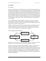
ATFM MODELLING CAPABILITY
AMOC
EEC Note No. 28/97
EEC Task E02
EATCHIP Task CFMU
Issued : December 1997
The information contained in this document is the property of the EUROCONTROL Agency and no part should be
reproduced in any form without the Agency’s permission
The views expressed herein do not necessarily reflect the official views or policy of the Agency..
REPORT DOCUMENTATION PAGE
Reference
EEC Note No 28/97
Originator
EEC - FDR
(Flight Data Research)
Security Classification
unclassified
Originator (Corporate author) Name/Location :
Sponsor
Sponsor (Contract Authority) Name/Location
Director CFMU
96, rue de la fusée
B-1130 Brussels
BELGIUM
Telephone: +32 2 729 90 11
EUROCONTROL Experimental Centre
BP15
91222 Brétigny-sur-Orge CEDEX
FRANCE.
Telephone: +33 (0) 1 69 88 75 00
Central Flow Management Unit
Title :
ATFM Modelling Capability - AMOC
Authors
A. TIBICHTE
M. DALICHAMPT
EATCHIP Task
specification
Date
Pages
Figs
Annexes
Ref.
12/97
x + 89
-
-
-
EEC Task No.
Sponsor Task No.
Period
E02
E02
1997
CFMU
Distribution Statement :
(a) Controlled by :
(b) Special Limitations (if any) :
(c) Copy to NTIS :
Descriptors (keywords) :
Head FDR
None
YES/NO
ATFM, AMOC, NASPAC, CFMU, CASA, Simulator, CARAT.
Abstract :
This document gives a detailed description of the AMOC simulator, developed at
EUROCONTROL Experimental Centre. It is intented for ATFM specialists and software
engineers familiar with simulation technology and with a general knowledge of the ATFM
concept and the CFMU daily operations. However, certain areas are adressed to software
engineers who will maintain or enhance the AMOC functionality.
This document has been collated by mechanical means. Should there be missing pages,
please report to:
Publications Office
EUROCONTROL EXPERIMENTAL CENTRE
B.P. 15
91222 Brétigny-Sur-Orge CEDEX
France
EUROCONTROL EXPERIMENTAL CENTRE
EEC Note No 28/97
ATFM MODELLING CAPABILITY
AMOC
BY
A. TIBICHTE
M. DALICHAMPT
SUMMARY
In July 1992, a potential role for the EUROCONTROL Experimental Centre to conduct
and support research into current and future ATFM, Air Traffic Flow Management,
systems was identified by the Directors of the EEC and CFMU, Central Flow
Management Unit.
Two tools NASPAC (National Airspace System Performance Analysis Capability) and
CASA (Computer Assisted Slot Allocation) were installed at the EEC and an ATFM
simulator, AMOC, was developed.
The main objective of this document is to show what kind of studies can be carried out
with AMOC, e.g. :
• Identify bottlenecks in a given airspace organisation.
• Evaluate the current CFMU operations.
• Define contingency plans (in case of TACT/CASA failure).
• Assess the benefits of new ATFM strategies (slot allocation, re-routing scheme,...)
This note is intended for ATFM specialists and software engineers familiar with
simulation technology and with a general knowledge of the CASA algorithm and the
CFMU operations. Enough detail is included to assist those wishing to understand the
overall architecture and functionality of AMOC, and those learning the system in order to
maintain, enhance or simply use AMOC to conduct studies.
AMOC: ATFM Modelling Capability
v
EUROCONTROL EXPERIMENTAL CENTRE
EEC Note No 28/97
INTENTIONALLY LEFT BLANK
AMOC: ATFM Modelling Capability
vi
EUROCONTROL EXPERIMENTAL CENTRE
EEC NOTE No 28/97
TABLE OF CONTENTS
1.0
Introduction...................................................................................................... 1
1.1
Intended Audience .................................................................................. 1
1.2
The Design and Evolution of AMOC..................................................... 2
1.3
What You Need to Run AMOC .............................................................. 2
1.4
AMOC Validation................................................................................... 2
1.5
What does AMOC offer?........................................................................ 2
1.6
About This Manual ................................................................................. 3
1.7
What You Should Know To Maintain AMOC........................................ 4
2.0
AMOC ............................................................................................................... 5
2.1
Overview................................................................................................. 5
2.2
The Topology of the old AMOC ............................................................ 5
2.2.1 Why NASPAC? .......................................................................... 6
2.2.2 The problems of simulating with NASPAC ............................... 6
2.3
The topology of the new AMOC ........................................................... 7
2.4
AMOC STRUCTURE ............................................................................ 8
2.5
Overview of the role of each AMOC parts............................................. 9
2.6
The Incremental and Iterative Nature of AMOC.................................. 11
3.0
Using AMOC: Simple steps........................................................................... 13
3.1
S0. Data Collection............................................................................... 13
3.2
S1. Generate AMOC Input files .......................................................... 13
3.3
S2. Sectors Throughput on the Raw Traffic.......................................... 14
3.4
S3. Regulation Schema......................................................................... 14
3.5
S4. Create Regulations and their corresponding flows ......................... 14
3.6
S5. Generate Traffic Volume................................................................. 14
3.7
S6. Slot Allocation................................................................................ 14
3.8
S7. Key Performance Metrics............................................................... 14
3.9
S8. Sectors Throughput on the Regulated Traffic................................. 14
3.10 S9. Loop over the process.................................................................... 15
4.0
How to get the CFMU Data?......................................................................... 17
5.0
AMOC user tools............................................................................................ 19
5.1
The AMOC main window .................................................................... 19
5.2
Starting up AMOC................................................................................ 19
6.0
CASA............................................................................................................... 21
6.0.1 Description of CASA algorithm............................................... 21
6.0.2 Running CASA......................................................................... 22
6.0.3 CASA input files ...................................................................... 22
6.0.4 CASA regulations file .............................................................. 25
6.0.5 CASA Script file....................................................................... 27
AMOC: ATFM Modelling Capability
NTROL EXPERIMENTAL CENTRE
EEC NOTE No 28/97
7.0
SelFlow ............................................................................................................ 31
7.1
Mode Of SelFlow Use .......................................................................... 32
7.2
Sectors aliases file................................................................................. 33
7.3
Aerodromes file .................................................................................... 33
7.4
Flows file .............................................................................................. 35
7.4.1 Centralized flows ...................................................................... 37
7.4.2 Decentralized flows .................................................................. 37
7.4.3 Operations on Flows................................................................. 37
7.5
Volume.................................................................................................. 38
7.6
Flow’s Period ........................................................................................ 38
7.7
fix file .................................................................................................... 39
7.8
Traffic file and how it is processed ....................................................... 39
7.8.1 Traject file................................................................................. 39
7.8.2 Crossings file ............................................................................ 40
7.8.3 Processing................................................................................. 41
7.9
Statistics................................................................................................ 42
7.10 Log file.................................................................................................. 43
8.0
DeliverCtot...................................................................................................... 45
8.1
Running DeliverCtot............................................................................. 45
8.2
Input...................................................................................................... 45
8.3
Output ................................................................................................... 46
8.4
How DeliverCtot processes................................................................... 46
9.0
PerfAnalysis.................................................................................................... 47
9.1
Running PerfAnalysis........................................................................... 47
9.2
Input...................................................................................................... 49
9.3
Output ................................................................................................... 49
10.0
FRED............................................................................................................... 51
10.0.1 Purpose of FRED...................................................................... 51
10.1 Controls of FRED ................................................................................. 51
10.2 Starting FRED ...................................................................................... 54
10.2.1 Flow Window ........................................................................... 54
10.2.2 Description of Flow Window ................................................... 55
10.2.3 Creating a flow ......................................................................... 56
10.2.4 Updating a flow ........................................................................ 56
10.2.5 Remove a flow .......................................................................... 56
10.2.6 Attach CASA regulation to a flow............................................ 57
10.2.7 De-attach a CASA regulation.................................................. 58
10.3 Airport Families window ...................................................................... 58
10.3.1 Description Of Airport Families window................................. 58
10.3.2 Creating an airport family ........................................................ 59
10.3.3 Updating an airport family ....................................................... 59
10.3.4 Remove an airport family ......................................................... 59
AMOC: ATFM Modelling Capability
I
EUROCONTROL EXPERIMENTAL CENTRE
10.4
10.5
10.6
10.7
10.8
EEC NOTE No 28/97
Flows Operations window .................................................................... 59
10.4.1 Description of the flows logical operations window ................ 60
10.4.2 Creating an operation on flows................................................. 61
10.4.3 Updating an operation on flows................................................ 61
10.4.4 Remove an operation on flows ................................................. 61
Save a scenario with FRED .................................................................. 61
Load a scenario with FRED.................................................................. 61
Information about a current scenario.................................................... 62
Exiting FRED ....................................................................................... 62
11.0
ATAC (Airspace Traffic dAta Capture) ....................................................... 63
11.1 Objective............................................................................................... 63
11.2 ATAC Module....................................................................................... 63
11.2.1 Output files ............................................................................... 63
11.2.2 Input files.................................................................................. 64
12.0
Flight Increase Processor Software .............................................................. 64
12.1 input files .............................................................................................. 65
12.2 Ouput files............................................................................................. 66
12.3 Processing ............................................................................................. 66
12.4 Running FIPS ....................................................................................... 67
13.0
The graphical User Interface of AMOC ...................................................... 69
14.0
AMOC Advanced Features ........................................................................... 71
14.1 AMOC Installation Instructions From a tape ....................................... 71
14.2 AMOC Installations Instructions From a tar file .................................. 72
14.3 Directory Descriptions.......................................................................... 73
14.4 src directory .......................................................................................... 74
14.4.1 SelFlow files ............................................................................ 74
14.4.2 DeliverCtot files........................................................................ 74
14.4.3 FIPS code files......................................................................... 74
14.4.4 PerfAnalysis code..................................................................... 74
14.5 CASA src .............................................................................................. 75
14.6 FRED src .............................................................................................. 75
14.7 com directory ........................................................................................ 75
14.8 Graphical User Interface Logical Structure.......................................... 76
14.8.1 Main Menu ............................................................................... 77
14.8.2 Menu Items............................................................................... 77
14.8.3 Dialog Boxes ............................................................................ 77
14.8.4 Actions...................................................................................... 78
15.0
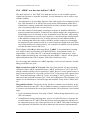
AMOC as a host test bed for CARAT ......................................................... 81
15.1 Why restructuring AMOC .................................................................... 82
15.2 Distributing AMOC .............................................................................. 82
15.3 AMOC processes .................................................................................. 83
AMOC: ATFM Modelling Capability
NTROL EXPERIMENTAL CENTRE
15.4
15.5
16.0
EEC NOTE No 28/97
The approach proposed......................................................................... 83
Roles and Responsibilities.................................................................... 84
ATFM Simulator’s capability ....................................................................... 87
16.1 What do we offer? ................................................................................ 87
AMOC: ATFM Modelling Capability
III
EUROCONTROL EXPERIMENTAL CENTRE
EEC NOTE No 28 /97
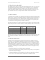
1.0 Introduction
In July 1992 a potential role for the EUROCONTROL Experimental Centre EEC to
conduct and support research into current and future air traffic flow management
ATFM systems was identified by the directors of CFMU, the Central Flow Management Unit and the EEC. The long term purpose of the research was to define and validate new flow management concepts. Two areas of short term study and research were
identified:
•
Evaluation and improvement of the Pretactical ATFM operations: This include the
identification of over-regulated or under-regulated sectors and analysis to suggest new solutions to maintain traffic within the declared capacities without any
excessive delays.
•
Evaluation and improvement of the Tactical ATFM system: This include the analysis of current ATFM measures to assess their effectiveness and delay costs, an
assessment of multiple restrictions on a single traffic flow to identify possible
redundancies; or worse, inconsistent duplications of effort.
The longer-term research is broad in scope. Ground delays are an effective but costly
means of maintaining traffic flows within limits, causing considerable disruptions to
airlines’ schedules. Research using the simulation capability might identify opportunities for improved efficiency in regulation, by applying more sophisticated operations research techniques than those currently applied. Other tactics, such as dynamic
rerouting, in response to identified imbalances between demand and capacity, are also
possible. Investigation of such possibilities may benefit the airlines companies and
passengers.
A centre of expertise was formed at EUROCONTROL Experimental Centre to implement the above recommendations and to conduct studies on behalf of the Central
Flow Management Unit CFMU.
1.1 Intended Audience
This manual is intended for the EEC ATFM specialists and software engineers familiar
with simulation technology, having a general knowledge of the CASA algorithm and
the CFMU daily operations. Enough detail is included to assist persons wishing to
understand the overall architecture and functionality of the AMOC system, and serves
as effective step in learning the system for those who will maintain, enhance or simply
use AMOC to conduct studies.
1.2 The Design and Evolution of AMOC
There never was an AMOC User Requirement Document , AMOC Software Requirement Document or AMOC Software Design Document. AMOC evolved to answer the
needs of the specific studies conducted at the Eurocontrol Experimental Centre to support the CFMU operations. This evolution is a continuous process in response to new
problems or requests from ATFM specialists.
AMOC: ATFM Modelling Capability
1
EUROCONTROL EXPERIMENTAL CENTRE
EEC NOTE No 28 /97
1.3 What You Need to Run AMOC
The AMOC system will run on any UNIX workstation that runs X11 server. You will
need Modsim and Simgraphics running on your workstation or server. Simgraphics
provides the graphical user interface, window system, and toolkit necessary to run
AMOC and compile AMOC interfaces. The UNIX workstation provides the C compiler and linker necessary to compile and link AMOC modules and interfaces.
1.4 AMOC validation
A validation study of AMOC was conducted in the framework of the FAP (Future ATM
Profile) project in support of the IPEAS Task Force (Indicators for the Performance of
the European ATM System). The validation traffic sample included the entire ECAC
zone, and was for Friday the 21st of June 1996 (22 161 flights). The regulation plan
was simulated was that applied by the CFMU on that day.
The following table shows a global comparison between AMOC results and the CFMU
delay Analysis for the 21st of June 1996 (ref.: weekly summary 1996, weeks 19 to 26).
AMOC
CFMU report (21/06/96)
Number of flights regulated
7056
6739
Number of flights delayed
3824
4303
Total ATFM delay (minutes)
91131
94238
Mean delay per delayed flight
24
22
Mean delay per regulated flight
13
14
Both the analysis of the sectors throughput and the comparison of the delays show that
the simulations with AMOC simulator can be considered close to the CFMU operations.
1.5 What does AMOC offer?
Scientific research and engineering development related to the ATFM, are relying
increasingly on computational simulation to augment theoretical analysis, experimentation, and testing. Many of ATC and ATFM problems are far too complex to yield to
mathematical analyses. Simulations play an even greater role in providing solutions to
our most challenging problems. In this context, The AMOC simulator was developed
to simulate a wide range of ATC and ATFM functions, which can be applied to carry
out studies to:
• identify the bottlenecks in a defined airspace organisation
• carry out a deep analysis of the CFMU operations (strategic and pre-tactical phases)
and evaluate proposed solutions
• evaluate new alternative ATFM strategies and evaluate new approaches to adopt in
case of TACT/CASA System failure (Preparation of contingency plans)
AMOC: ATFM Modelling Capability
2
EUROCONTROL EXPERIMENTAL CENTRE
EEC NOTE No 28 /97
• validate the application of optimisation techniques (operations research, constraintbased approach) to reduce system-wide delays and congestion
1.6 About This Manual
This manual describes AMOC and contains fifteen chapters, including this one. If
you’re new to AMOC and the ATFM simulations, you should finish reading this introduction and then go to chapter two. It shows you the AMOC structure and describes
briefly its components.
Chapter Three: Gives simple steps to guide you in conducting an ATFM study with
AMOC.
Chapter Four: Gives you valuable information in obtaining the CFMU data necessary
to start a simulation.
Chapter Five: describes the AMOC main window from which you can run any AMOC
component.
Chapter Six: Describes the CASA algorithm, the input and output files format, the
CASA services call and how to run CASA from AMOC main window.
Chapter Seven: Gives a short overview about the centralised and decentralised strategies, the SelFlow input and output files and how to run SelFlow
Chapter Eight: Describes DeliverCtot and gives the format of its input files
Chapter Nine: Shows how to use PerfAnalysis module to analyse the key performance
measures of an ATFM strategy.
Chapter Ten: Contains valuable information about FRED tool, and how to use its four
panels windows to create and update regulations and their correspondents flows.
Chapter Eleven: Describes the ATAC module responsible for formatting the CFMU
traffic data.
Chapter Twelve: Describes the Flight Increase Processor Software which generates
additional flights demand for simulation studies.
Chapter Thirteen: Describes the physical structures of AMOC directories and their
contents. It gives also a detailed description of the Objects that make AMOC Graphical
User Interface GUI.
Chapter Fourteen: Shows how CARAT can be integrated into AMOC for its validation
and testing.
Chapter Fifteen: Describes the kind of studies that could be conducted using AMOC.
A glossary and a definition of special terms are at the end of this document.
AMOC: ATFM Modelling Capability
3
EUROCONTROL EXPERIMENTAL CENTRE
EEC NOTE No 28 /97
1.7 What You Should Know To Maintain AMOC
This part addresses to people who will maintain AMOC. It assumes that you are familiar with UNIX, HP-UX, X11 server, the C programming language. It’s particularly
important that you know the Object-Oriented language Modsim and Simgraphics.
For more information about these topics, you can consult:
• The HP-UX Reference Manual for information about UNIX and HP-UX.
• The C Programming Language by Kernighan and Ritchie (or other reputable C
books) for rules of programming in C.
• Modsim II User’s Manual and Reference Manual.
• Simgraphics II User’s Manual.
• XLib Reference Manual and XLib Programming Manual. These manuals are useful
to understand the warning program writing with Xlib library.
• X Window System User’s Guide.
• Object-Oriented Analysis And Design with Applications by Grady Booch.
AMOC: ATFM Modelling Capability
4
EUROCONTROL EXPERIMENTAL CENTRE
EEC NOTE No 28 /97
2.0 AMOC
2.1 Overview
Traffic growth and changes in traffic patterns have caused increasing congestion and
delay in European airspace. The Central Flow Management Unit (CFMU) continually
seeks and develops methods to improve traffic flow management on an European scale
to reduce delay and congestion. As part of this effort, the CFMU tasked the Eurocontrol Experimental Centre EEC with assessing new ATFM alternatives to generate better
flow management strategies than those used currently. The EEC tackled the development of an ATFM simulator to experiment with new ways to resolve the problem of the
European airspace congestion. The EEC ATFM simulator was born, and, through successive attempts to make it better, a final version of this simulator was shaped in the
form of AMOC.
The ATFM MOdelling Capability AMOCwas designed to provide a test-bed for a
wide spectrum of studies. It helps the executive planners and managers to address
issues related to the airspace overload, the evaluation of a new ATFM strategy and the
improvement of current or future operations.
AMOC is a collection of software that converts information concerning the structure
of, and demand for, an airspace into measurements of performance of the system.
AMOC is primarily based on the existing CFMU Computer Aided Slot Allocation
CASA. CASA was incorporated as a fundamental component.
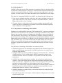
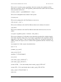
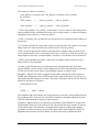
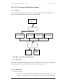
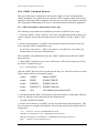
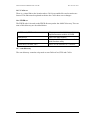
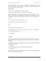
2.2 The topology of the old AMOC
-D
fic
raf
t
reg
SELFLOW
ul
ate
dt
raf
fic
4
EURONASPAC
CASA
t
De
lay
DeliverCtot
t
lo
lis
S
By topology, we mean the basic physical building components of the system and how
those parts are interconnected to provide the overall behaviour of AMOC.
AMOC was based on the existing CFMU programme: Computer Aided Slot Allocation CASA, and the FAA National Airspace Performance Analysis Capability
NASPAC. EEC NASPAC was modified to be tailored to European airspace caracteristics and is now known as EuroNaspac. The two simulation tools, NASPAC and CASA,
were used in a complementary fashion.The two tools working together provided an
end-to-end capability to convert the theoretical concept of a traffic flow rate into specific flight-by-flight effects. The SELFLOW and DeliverCtot were responsible for formatting and sending data.
AMOC: ATFM Modelling Capability
5
EUROCONTROL EXPERIMENTAL CENTRE
EEC NOTE No 28 /97
2.2.1 Why NASPAC?
NASPAC reflects the way the FAA approach to congestion which is completely different from the CFMU perspective. The FAA is concerned with congestion problems specifically around airports while, the CFMU is concerned with congestion at any level
(airports, en-route sectors). This makes the number of the constraints to resolve larger.
The choice of integrating NASPAC into AMOC was dictated by the following facts:
1. There was no available simulator, at the time, able to deal with data for a large airspace such as the ECAC zone, and to calculate in reasonable amount of time the
flight profile and the sectors’ loadings.
2. The main objective of the earlier studies was not to produce operationally valid
results, but rather to demonstrate the potential of an ATFM simulation capability
and to validate the CASA algorithm.
2.2.2 The problems of simulating with NASPAC
Problems arose with NASPAC when the CFMU asked the EEC to prepare contingency
plans based on real traffic. Because NASPAC is a prototype simulation of large-scale
airspace and air traffic systems, the flight profile calculation is based only on the aircraft performance. Based solely on this information, NASPAC produces mistakes in
the en-route sectors loadings. ATC constraints were introduced into NASPAC to model
flight profiles more accurate but it’s difficult to feed it manually with all the european
ATC constraints, and, it is a waste of time when the traffic sample sent to us by the
CFMU contains all the information needed ( flight profiles based on the aircraft performance, requested level and the ATC constraints and entry time in all the en-route
sectors).
The problems of simulating with NASPAC are sumarized below:
• NASPAC Preprocessor uses about thirty input data files; the simulator engine uses
about sixteen differents input data files; and the Postprocessor uses about sixteen
differents input data files,
• NASPAC modules are written in different languages: Fortran, Pascal, C, Simscript,
Cshell, Dataviews, XView which make it difficult to maintain or improve the
NASPAC functions. Moreover, NASPAC is not portable, and runs only on Sun
workstation,
• NASPAC uses a linear regression to calculate the en-route time spent between
resources. These times depend on the following formula that encompasses uncertainty: en-route time = a*distance^b*r, where r is a mean squared error of the residual which is used by NASPAC to add a random value to the en-route time.
Moreover, the values for the regression coefficients are calculated based on data collected from American airlines (which are usually reluctant to publish their data:
another doubt about the accuracy of the coefficients).
• NASPAC introduces an implicit delay at all modeled airports by using the airport
service time mechanism.
• To model the operations at an airport, a full description of the gaussian curve at that
airport should be input.
AMOC: ATFM Modelling Capability
6
EUROCONTROL EXPERIMENTAL CENTRE
EEC NOTE No 28 /97
2.3 The topology of the new AMOC
We found it useful to evolve AMOC functions using CASA as the backbone of our
simulation environment, and developing necessary tools around it . This provided two
major advantages. First, we gain a significant amount of the simulation time by incorporating a tool that does not recalculate any profile or sector time entrance but only
extracts the required information, from the CFMU data, into a readable format for SelFlow. Secondly, we enhance the sectors hourly distribution and thus the plan of regulations by using the same profile and sectors pierced as the CFMU. Thus the studies
performed were as close as possible to the CFMU operations.
AMOC: ATFM Modelling Capability
7
EUROCONTROL EXPERIMENTAL CENTRE
EEC NOTE No 28 /97
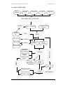
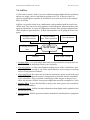
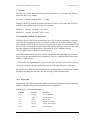
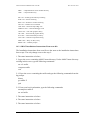
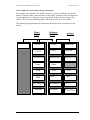
2.4 AMOC STRUCTURE
TACT
archives
SPORT
STANLY
LATCC
MADAP
The CFMU URS_TOOLSET
STAIR
forecast
file
New sectors
New routes
Airports & fix
location
ALL_FLIGHT
FIPS
ATAC
FAMEsec
FAMErte
4D
Profiles
Sector
crossings
protected
fix location
SelFlow
Sectors
aliases
Flows
FRED
Flows
throughput
DeliverCtot
Environment
Traffic
Volume
Slot list
Regulations
CASA
CASA script
AMOC: ATFM Modelling Capability
PerfAnalysis
ISA
8
EUROCONTROL EXPERIMENTAL CENTRE
EEC NOTE No 28 /97
The previous figure depicts the high-level architecture of the AMOC Simulator. Few
standalone modules interact with each other to provide the basic services that will be
described later. AMOC is viewed as a set of hierarchical components collaborating
through their interfaces. This document does not address the details about the internal
representation of the components.
The above diagram provides a schematic representation of AMOC. From this diagram,
we can conclude that it is simple, clean and uncluttered. This hierarchic structure is a
major facilitating factor allowing users to focus their attention on the data flow and the
way the data are manufactured to achieve a given strategy. Each module can be refined
independently or replaced entirely by new software without affecting the AMOC
architectrure (it is the principle of “plug and play”). Each module and its individual
input and output will be described later.
2.5 Overview of the role of each AMOC parts
It is important to realise that the architecture of AMOC is a function of its component
as well as the hierarchic relationships among these components. This rule provides a
clear separation of responsibilities among the various components of AMOC, making
it possible to study each part in relative isolation.
URS_TOOLSET One of the most important and time consuming task in a fast time
simulation is acquiring accurate and timely data. Thanks to the User Requirement Section at the CFMU, we can now use an array of data available at the CFMU through
their tool called urs_toolset. The TACT system produces daily archive data at the end
of each operational day. This archive contains valuable information about flights, operational events and regulations. There are also several sources of data in Europe used at
the CFMU :
• The French SPORT system flight data,
• The German STANLY system flight data,
• The English LATCC system flight data,
• The Maastricht MADAP system flight data.
All these data are converted to a very specific format called ALL_FLIGHT format. The
software used for converting these data is a UNIX graphical interface called
urs_toolset.
CASA The Computer Aided Slot Allocation is used to enforce the ATFM measures
whenever a volume exceeds its projected capacity. It assigns the take-off time for the
flights crossing the congested area by comparing their ETOs (Estimated Time Over)
and the reference time of the available slots. An overload can occur at the end of the
period of activation if no slot is available. The CASA algorithm is a simple heuristic
based on the principle of first-planned, first-served.
PerfAnalysis The Performance Analysis module measures the balance between the
needs of airspace users to meet their schedules, and the needs of regulators to restrict
flow to safely manageable levels. This module analyses the impact of a proposed
ATFM strategy in terms of total delay, throughput deviation, regulations redundancy
and bunching.
AMOC: ATFM Modelling Capability
9
EUROCONTROL EXPERIMENTAL CENTRE
EEC NOTE No 28 /97
DeliverCtot This module is responsible for updating the crossing times of the en-route
sectors, and the times over navaids in the routes of the regulated flights. It extracts the
new calculated take-off times (CTOT) generated by CASA algorithm into the SelFlow
input files, traject and crossings files.
SelFlow The Flight Selector chooses those flights that meet the criteria of selection of
one or more of the regulations and writes :
• the relevant information concerning them in a format readable by CASA,
• the hourly distribution of each defined flow.
To completely describe a regulation, one must specify the airspace to be regulated in
terms of flows, the period of activation and the rate at which flights will be accepted.
This information is put into several files:
• The period of activation and the rate are put in the “Regulations” file which is an
input to CASA,
• The regulated airspace is specified in several ways depending on the complexity of
the resulting flow. This description is put in the “Flows” file which is an input to SelFlow.
•
FRED The Flows and Regulations EDitor is a graphical user interface that allows the
creation and update of CASA regulations and their corresponding area (flows). It is
composed of four panels:
• a panel for defining simple flows
• a panel for defining complex flows (ie logical operations on flows)
• a panel for defining CASA regulations
• a panel for defining the used family of airports.
ATAC The Airspace Traffic dAta Capture is a data generation tool permitting the creation of two input files: traject and crossings. The CFMU TACT system produces
archive data at the end of each operational day. These archive data contain valuable
information about what happened on that operational day including information about
the traffic. The ATAC module reads the traffic file to produce SelFlow input files.
FIPS The Flight Increase Processor Software tool uses DED.4 Traffic Statistics and
Forecasts (STATFOR) to generate new flight plans to simulate an operational day in
the future. The STATFOR is a flow based traffic growth. With the FIPS tool, you don’t
need to run ATAC, because FIPS , as shown in the above figure, works directly on
crossings and traject files.
STAIR The Software for CFMU Traffic Analysis and Increase pRocessing is an other
tool to generate additional flights directly from the ALL_FLIGHT file. The output of
this module is an ALL_FLIGHT file containing the original file plus the extra flights.
AMOC: ATFM Modelling Capability
10
EUROCONTROL EXPERIMENTAL CENTRE
EEC NOTE No 28 /97
FAME The FAst Modifier Environment is a software tool to enforce the changes in the
environment( Routes or sectors). It allows the assignment of new routes to certain
flights or modification of an old set of sectorisation to a new one. The way FAME will
process is simple and can be summarized as follow:
• If the changes affect the sectorisation, FAMEsec will recalculate the sectors time
piercing without modifying the 4D trajectories of the flights crossing these sectors,
• If the changes affect routes or both routes then FAMErte will recalculate the profiles
and sectors time piercing for only those flights affected by the change in the environment.
2.6 The Incremental and Iterative Nature of AMOC
The process of building an acceptable ATFM strategy for smoothing traffic in congested areas without causing an excessive delay is incremental and iterative. This
incremental and iterative nature is evident in the process of elaborating a complete and
cohesive ATFM strategy because of the strong coupling between regulations.
Because of this complexity in the flows network, it is not evident to know in advance
the number of iterations to converge toward an acceptable ATFM Scheme. As experience accumulates, it turns out that the convergence toward the threshold of stability is
around 3 iterations.
AMOC: ATFM Modelling Capability
11
EUROCONTROL EXPERIMENTAL CENTRE
EEC NOTE No 28 /97
INTENTIONALLY LEFT BLANK
AMOC: ATFM Modelling Capability
12
EUROCONTROL EXPERIMENTAL CENTRE
EEC NOTE No 28 /97
3.0 Using AMOC: Simple steps
This section outlines how AMOC could be used quickly.
3.1 S0. Data Collection
One of the most important and time consuming tasks in applying the ATFM Simulator
System AMOC is acquiring accurate and timely data. Our data provider is the CFMU.
As outlined earlier in this report, several data sources are available at the CFMU and
can be converted to a specific and unique format called ALL_FLIGHT. The acquisition
of this file is the starting point of the AMOC utilisation. This file contains valuable
information about the flight pattern, i.e. flight callsign, departure and arrival airports,
the list of overflown fixes and the list of crossing sectors etc. This format will be discussed further later.
Three files are necessary to start a simulation with AMOC:
• The ALL_FLIGHT file for an operational day,
• The location of all fixes and airports (ICAO location indicator, latitude and longitude),
• A file containing the aliases, or the definition of all subsequent non-elementary sectors. For example, if one wants to use the sector AB, which is a combination of the
elementary setors A and B, he should specify it clearly as ‘AB: A B’ or, if one wants
to use a preferred name C rather than the name D, he must define it in this file as ‘C:
D’.
AMOC does not need the geographical physical location of the used sectors. One can
start an ATFM simulation with AMOC without describing the location of the crossing
sectors. What is valuable for AMOC is the ICAO name of the sectors, and the time of
piercing for all the flights.
3.2 S1. Generate AMOC Input files
The ALL_FLIGHT is processed again by the ATAC module to generate two files:
• traject file containing information about the trajectory of each flight in 4 dimensions. This information relates to the overflown fixes, the estimated time over (ETO)
and the altitude.
• crossings file containing information about the en-route sectors for each flight. This
information relates to the used sectors, the time of entry and the time of exit.
The ALL_FLIGHT is generated by urs_toolset from an operational day obtained from
the Central Flow Management Unit CFMU via network or magnetic tapes . Currently,
the process of converting the ALL_FLIGHT data by ATAC needs manual intervention
to correct flights with errors, and to enter the locations of missing fixes and airports.
3.3 S2. Sectors Throughput on the Raw Traffic
Once the ALL_FLIGHT file has ben converted, one might run SelFlow to generate the
demand for all sectors configuration to get an exact snapshot of what could be hap-
AMOC: ATFM Modelling Capability
13
EUROCONTROL EXPERIMENTAL CENTRE
EEC NOTE No 28 /97
pened if no ATFM measures have been adopted during this operational day or to search
for an other ATFM strategy that best fit to the traffic pattern and the airlines schedules.
3.4 S3. Regulation Scheme
Once all the sectors are analysed and the congested ones identified, prepare your regulation scheme to protect overloaded sectors. The AMOC Simulator runs a regulation
schema based on centralised flows, decentralised flows, or a mix of both flows. It’s up
to the strategic planner to decide which approach to adopt in order to smooth the traffic.
The strategic decisions taken at this phase have sweeping implications on the final
result. The success of the study is dependent on the strategic planner’s skill and his
ability to deal with the complexity of the traffic network.
3.5 S4. Create Regulations and their correspondents flows
Run FRED to convert your regulation schema into flows definition (input to SelFlow)
and their corresponding regulations (input to CASA). FRED also creates a CASA scenario if it does not exist. Once FRED has completed execution, all regulation files are
saved to the appropriate CASA input directory.
3.6 S5. Generate Traffic Volume
First, run SelFlow to extract flights belonging to one or several flows. The output of
SelFlow is a traffic volume file to be used as input to CASA, and a statistic file concerning flows’ demand.
3.7 S6. Slot Allocation
Run CASA by specifying the name of CASA scenario. The outputs of CASA are a
trace file containing all slot allocations and update messages, and a report file for each
regulation.
3.8 S7. Key Performance Metrics
PerfAnalysis uses the CASA report files to extract the key output metrics. It identifies
the redundant or the most restrictive regulations.
3.9 S8. Sectors Throughput on the Regulated Traffic
At this phase, you should inject the new departure times given by CASA (CTOT) into
traject and crossings files, and run SelFlow to see the impact of the above strategic
decisions on the traffic pattern, and the rippling effect on the non-protected sectors.
3.10 S9. Loop over the process
The Computer Assisted Slot Allocation CASA implements a heuristic search based on
a first-planned first-served principle in order to distribute the delays among flights as
fairly as possible. However, it does not take into account the dependencies between
flows; one regulated flow can generate overload anywhere in the airspace where it is
not expected. So, in order to smooth all the traffic, an iteration process is needed. The
number of iterations, before the stability threshold, is not known in advance: this
AMOC: ATFM Modelling Capability
14
EUROCONTROL EXPERIMENTAL CENTRE
EEC NOTE No 28 /97
number depends on the distribution complexity of the traffic and the reliability of the
regulation schema, (On average, the number of iterations is equal to three for an elaborated regulation schema).
The loop over can start from step 1 (S1) or step 2 (S2) depending on the difficulty and
the requirement of the study (centralised or decentralised flows, rerouting ...)
AMOC: ATFM Modelling Capability
15
EUROCONTROL EXPERIMENTAL CENTRE
EEC NOTE No 28 /97
INTENTIONALLY LEFT BLANK
AMOC: ATFM Modelling Capability
16
EUROCONTROL EXPERIMENTAL CENTRE
EEC NOTE No 28 /97
4.0 How to get the CFMU Data?
As outlined in the AMOC data diagram, the input traffic file to AMOC is an
ALL_FLIGHT file which should be processed through ATAC module to get crossings
and traject files.
There are several ways to get the ALL_FLIGHT file for a CFMU operational day:
(1) From TACT daily archive data. At the end of the operational day TACT produces an
OPLOG file. This file must be processed through the urs_toolset to get the
ALL_FLIGHT file,
(2) You can get the OPLOG or the ALL_FLIGHT file for an operational day by asking
the User Requirement Section URS of CFMU.
(3) There is a databank of the ALL_FLIGHT files available at the EEC
(4) You can access the ALL_FLIGHT files from the EEC robot.
(5) There is a progressing project called COFEE at the EEC aiming at providing a
unique format file to all the EEC simulators. This tool will generate not only a traffic
data but also an environment data from the ARC data available at the CFMU.
AMOC: ATFM Modelling Capability
17
EUROCONTROL EXPERIMENTAL CENTRE
EEC NOTE No 28 /97
INTENTIONNALY LEFT BLANK
AMOC: ATFM Modelling Capability
18
EUROCONTROL EXPERIMENTAL CENTRE
EEC NOTE No 28 /97
5.0 AMOC user tools
As shown in the data flow diagram, the AMOC simulator has a structure of cooperative
modules. Each module has its own environment and performs a specific task. They
exchange information to present a complete and cohesive system. The design decision
was to minimise the tremendous amount of cross-coupling among the components and
twisted flows of control which would otherwise threaten the reliability and integrity of
the AMOC and certainly obscure the overall clarity of the system.
The goal in designing and connecting individual software modules is to balance the
three goals of simplicity, consistency, and efficiency. The design pieces resulting from
this approach represent a tighter coupling of data and functionality leading to flexibility
in the sense of swift adaptability to changes in problem specifications.
This section describes the components that built the AMOC simulator. The most
important part of the simulator is the Computer Aided Slot Allocation CASA.
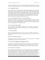
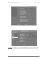
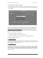
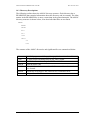
5.1 The AMOC main window
The figure above shows the AMOC main window. It is the window that appears when
AMOC is launched. From this window you are able to access all the components of the
AMOC Simulator. The window bar has three different menu titles: Run, Files and Utilities. At the time of writing this report, the functions in the Utilities menus were not yet
implemented, only the functions provided by Run and Files menu were accessible.
Through the Run menu you can access all the components described above . In the following sections we are going to briefly show how to run AMOC and its sub-components.
5.2 Starting up AMOC
The AMOC is a UNIX graphical interface. It can be run directly on any UNIX workstation or X-terminal, or on a PC running on X Window configuration. To start running
AMOC, open an hpterm window, go to the AMOC bin directory and at the prompt,
type “amoc”, then press return.
Now the graphical user interface appears at the top left of your screen.
You can start AMOC remotely from any machine. Below, are described the steps to follow in order to run it remotely.
AMOC: ATFM Modelling Capability
19
EUROCONTROL EXPERIMENTAL CENTRE
EEC NOTE No 28 /97
• add the name of the remote machine containing amoc executable programs as the
authorized machines to connect to your display server by typing: xhost +
remote_machine
• remote logging onto the machine host where amoc is installed.
• setup the display environment by typing: export DISPLAY=your_display:0.0
• then type: amoc
AMOC: ATFM Modelling Capability
20
EUROCONTROL EXPERIMENTAL CENTRE
EEC NOTE No 28 /97
6.0 CASA
Clearly CASA is the most important element of the AMOC. Its responsibilty is to
smooth the traffic in the protected area without underutilising the global capacity. The
CASA algorithm is a simple heuristic based on the principle of the first-planned, firstserved. But, this principle is not always respected because of the tight coupling among
the constraints.
6.0.1 Description of CASA algorithm
For each regulated point, area or aerodrome, CASA constructs and administers a list of
slots called the slot allocation list. A regulation may be divided into sub-periods, each
sub-period being assigned a rate. CASA uses these items initially to construct an empty
slot allocation list. For instance, a four-hour sub-period associated with a basic rate of
28 flights per hour, would result in a slot allocation list made up of 112 slots separated
from one another by approximately 2 minutes.
Each flight is given a provisional slot based on the order of its Estimated Time Over
(ETO) the restricted area and the reference time of the closest slot. This initial reservation is internal to the system and is subject to amendment.
When CASA receives new flight data, it tries to pre-allocate the slot that best fits the
requested Estimated Time Over (ETO) the reference point of the flow-controlled zone.
• if that slot is free, it is assigned to the flight, which thus suffers no delay
• if that slot is already pre-allocated to a flight which is planned to overfly the
restricted location after the new flight, then the later flight takes the slot. Of course,
the consequence can be a chain reaction, because the flight whose slot has been
taken tries to recover another slot, possibily by taking the slot of another flight, etc.
• if that slot is already allocated, it cannot be taken by a flight candidate for preallocation.
AMOC: ATFM Modelling Capability
21
EUROCONTROL EXPERIMENTAL CENTRE
EEC NOTE No 28 /97
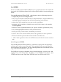
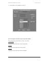
6.0.2 Running CASA
The first thing you may have to do is to run AMOC if it is not already done. Once the
AMOC main window appears on the top left corner of your screen:
• Select the menu item Casa from the Run menu.
• In the window that appears, click and enter the name of the CASA scenario to run.
The CASA scenario is the name of the directory where all the required input files
are. If the name of your CASA scenario is “test”, the input files are under “/net/
CASA_SERVER/users/casa/casa07/test”. The CASA SERVER will be explained
below.
• In the CASA SERVER textbox, enter the name of the host machine where the
CASA executable files are installed.
• In the ORACLE SERVER textbox, enter the name of the host machine where the
CASA Oracle Database is installed.
• Click onto the Ok button to activate the execution of CASA or the Cancel button to
close the window without running CASA.
When CASA is running, the window is closed and all the information about the status
of CASA execution is displayed on the hpterm window from where you launched
AMOC. Once CASA finishes its execution, the window appears again. Click onto the
Cancel button to get rid of it.
6.0.3 CASA input files
CASA (mode SIMCA) takes three files as input data files. Multiple versions of these
files are maintained to describe differents ATFM strategies.
The Traffic Volume file: This is the input file, generated by SelFlow, to CASA. Each
line is a message to CASA identifying the flight (callsign, take-Off time, list of regulations names and their corresponding time over). In the real world, the CFMU TACT
system receives its input from STRAT (flight data known long in advance) and IFPS
(flight data known at the day of the take off, or the day before). The TACT System
AMOC: ATFM Modelling Capability
22
EUROCONTROL EXPERIMENTAL CENTRE
EEC NOTE No 28 /97
compares air traffic demand with ATC capacities. Whenever demand is projected to
exceed capacities, TACT selects flights and sends them to CASA. In our study here at
the EEC, the data supplier is SelFlow.
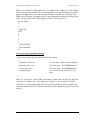
The file is a sequence of line of the following format:
(change_flight_data <flight_data> <concerned_regulations>)
The following two sections describe , respectively, the format of flight_data and
concerned_regulations.
flight data format
ITEMS
<category>string
COMMENTS
one of the strings [PLAN_DATA,
AIRBORNE_DATA, CANCELLATION, SRR]
<external_message>boolean
indicates if the input to CASA is caused
due to an external message ie a message
coming from the AO or an internal
message ie a regulation activation
unique identifier of the flight
call sign
one of the strings [RPL, PFD, IFPL]
<flight_reference>format
<aircraft_id>string
<flight_origin>string
<late_filer>boolean
<late_updater>boolean
<general_exempted>boolean
<confirmed_flight>boolean
<EOBT>big_time
<ETOT>big_time
<atot>big_time
AMOC: ATFM Modelling Capability
23
EUROCONTROL EXPERIMENTAL CENTRE
EEC NOTE No 28 /97
Below, is a description of flight data for a given flight with “AFR5342” as the callsign
and 1 as the aircraft identifier (The aircraft identifier is an internal number that distinguishes the flight and resolves the problem of flights using the same callsign). This
flight is not a late filer, late updater and it is not exempted from all the crossing regulations. The day of departure of this flight is 970205 ( 5 February 1997)
PLAN_DATA
T
1
“AFR5342”
IFPL
F
F
F
F
“970205075500”
“970205080000”
nil
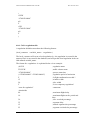
list of concerned regulations format
A list of concerned regulations has the following format:
(
<regulation_reference>
<estimated_time_over>
<actual_time_over>
<exempted_flag>
; It is the name of the crossed regulation
;It is of the type “YYMMDDhhmmss>
;It is of the type “YYMMDDhhmmss”
; It is a boolean flag and takes F or T
value
)
Note: YY : the year in 2 digits; MM : the month in 2 digits; DD : the day in 2 digits; hh
is the hour in 2 digits; mm : is the minutes in 2 digits; ss : the seconds in 2 digits.
Overleaf, it is a description of the list of concerned regulations. In this example, the
concerned regulations are rUGW and rUH which protects respectively the sector UGW
and UH.
AMOC: ATFM Modelling Capability
24
EUROCONTROL EXPERIMENTAL CENTRE
EEC NOTE No 28 /97
(
rUGW
“970205100000”
nil
F
rUH
“970205103000”
nil
F
)
6.0.4 CASA regulations file
A regulation definition must have the following format :
(local_construct <variable_name> <regulation>)
The local_construct will create a local regulation (i.e. the regulation is created in the
memory but it is not stored in the database) and will put this local regulation in the variable named variable_name.
The format for <regulation> is explained below via an example:
(rUGW
TFrUGW
“970204200000”
(“970205060000” “970205180000”)
F
15
20
T
“note for regulation”
;;thresholds
60
10
30
35
15
25
AMOC: ATFM Modelling Capability
; regulation name
; traffic volume name
; process start time
; regulation period of activation
; Is flight confirmation needed ?
; window width
; slice width
; Is it a temporary regulation ?
: comments
; maximum flight delay
; maximum flights at the period end
slots
; slice overload pecentage
; segment delay
; unused segment slot percentage
; segment overload slot percentage
25
EUROCONTROL EXPERIMENTAL CENTRE
30
;; a list of subperiods.
;; The 3 inner elements - period, normal
rate, pending rate - can be repeated
(
(“970205060000” “970205180000”) 10 2
)
;; a list of timeband width
EEC NOTE No 28 /97
; time band equity
;; to have a correct regulation, last element
must be > 1440.
(120 180 2000)
;; a list of timeband allowance subperiods.
;; The 2 inner elements - period + allowances - can be repeated.
;;the normal_rate_percentage +
pending_rate_percentage
;; must be repeated for each timeband width
(
(“970205060000” “970502180000”)
(34 34
33 33
33 33)
)
;; a list of supplementary subperiods. Note:
list can be nil
;; the 2 inner elements - period + supplementary rates - can be repeated.
nil
)
AMOC: ATFM Modelling Capability
26
EUROCONTROL EXPERIMENTAL CENTRE
EEC NOTE No 28 /97
6.0.5 CASA Script file
The script file is a text-based file. It contains a set of service calls that will be routed to
the regulation package in order to perform a specific task.
A service call is a process that will trigger a well-defined action. Each service call is
preceeded by opening parentheses, terminated with closing parentheses and may have
asociated parameters.
Only a few services calls are used for running CASA into AMOC. It should be noted
that the scope of service calls used at TACT level is very large. Below we will describe
the purpose of each service call we use.
(1) (trace <boolean> <boolean>)
Trace is used to enhance the output of CASA. The first field of this service instructs
CASA whether or not to print the result of each service. The second field instructs
CASA whether or not to print full details of each service encountered, along with the
full associated parameter list.
(2) (continue_on_error <boolean>)
This service is used to affect the behaviour of CASA in response to failure conditions.
If a service fails, either through script syntax errors or CASA application rejects the
requested action, a flag is set by CASA to control the continuation of the process. If the
boolean is False, CASA will continue execution, otherwise it will stop in case of any
sevice call failure. By default the continue_on_error flag is set to false.
(3) (auto_end_of_list <boolean>)
The purpose of this service is to avoid having to call the “end_of_list” after each regulation activation. When a regulation is activated, the flights concerned by this new regulations must be passed to CASA using the service change_flight_data. During the
activation of a regulation, the allocation of slots is slightly different. It is thus required
to indicate to CASA that the initial list of flights is terminated. This is done using the
end_of_list service
(4) (initialise <boolean> <“yymmddhhmmss”>)
This service is used to initialise the regulation package.
(5) (set_server)
This service is used to initialise the regulation package in server mode.
(6) (call <file_name>)
This service groups several service calls in a file and execute them in one call.
(7) (create <regulation_name>)
AMOC: ATFM Modelling Capability
27
EUROCONTROL EXPERIMENTAL CENTRE
EEC NOTE No 28 /97
This service is used to create a regulation. After the creation, the regulation will be
taken into account by CASA. The regulation_name must be the same as the one used in
local_construct call service.
(8) (time_control <“yymmddhhmmss”> <step>)
This service manipulates time within CASA system
(9) (start_test)
This service prompts the Ada Test Harness to start a test.
(10) (execute <“test”>)
This service indicates to the Ada Test Harness that a test is about to be started.
(10) (done)
This service indicates to the Ada Test Harness that some check services are to be
called.
(9) (report <regulation_name> <boolean> <file_name>)
This service indicates to CASA that a report should be produced for a defined regulation. If the <boolean> flag is True (T), a report is generated for the regulation, and the
ouput file is <file_name>. If the <boolean> flag is False (F), no report is generated. In
AMOC context, the report service is called for all regulations with the <boolean> flag
set to T.
An example of a CASA script is described below:
(trace T F)
(continue_on_error F)
(auto_end_of_list T)
(initialise T “970201200000”)
(set_server)
(call “make_regul_rUGW.1997”)
(call “make_regul_rUH.1997”)
(create rUGW) ; if it is not already done in make_regul_rUGW.1997
(create rUH) ; If it is not already done in make_regul_rUH.1997 file
(time_control “970201235900” 5)
(start_test)
AMOC: ATFM Modelling Capability
28
EUROCONTROL EXPERIMENTAL CENTRE
EEC NOTE No 28 /97
(execute “test_1”)
(done)
(call “make_flights.el”)
(report rUGW T reportUGW.1997)
(report rUH T reportUH.1997)
AMOC: ATFM Modelling Capability
29
EUROCONTROL EXPERIMENTAL CENTRE
EEC NOTE No 28 /97
INTENTIONALLY LEFT BLANK
AMOC: ATFM Modelling Capability
30
EUROCONTROL EXPERIMENTAL CENTRE
EEC NOTE No 28 /97
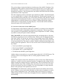
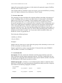
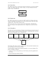
7.0 SelFlow
CASA works in passive mode. It receives information about flights and the regulations,
and tries to assign a slot to each flight according to its ETO. It does not know in
advance which flights to regulate or which flows to be protected. This is the responsibility of SelFlow.
SelFlow was specified with close collaboration with operational staff involved in the
ATFM study. The aim was to help regulators in identifying the mainstream flows and
applying regulations. It selects the flights that comprise flows through regulated parts
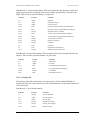
of the airspace at specified times. Its basic functionalities can be grouped in four categories:
Grouping of sectors
and sector aliases
Crossings and traject
files
Statistics
Airport Families
And flows operations
SelFlow
Flows Definition
fix file(if any)
CASA Traffic Volume
• Creation Phase : we create empty flows objects, airport families and protected volumes based on the definitions made by the regulators.
• Extraction Phase: we only select flights belonging to one of the created flows, and
departing from or arriving to, one of the airport families, and crossing or overflying
one or several protected volumes.
• Processing Phase: the sectors are described as elementary entities to allow the regulators freedom to adapt the airspace configuration to the traffic and the availability
of the controllers. Thus, a dynamic restructuring of the airspace in the process is
taken into account. SelFlow also prepares flights that would be exempted by CASA.
• Merging Phase: It gives the flexibilty to merge in the same process run, centralised
and decentralised flows.
• Formatting Phase: SelFlow formats information about flights under regulations into
file for use by CASA.
• Statistic Phase: SelFlow generates statistics demand for all defined flows along their
lifetime.
AMOC: ATFM Modelling Capability
31
EUROCONTROL EXPERIMENTAL CENTRE
EEC NOTE No 28 /97
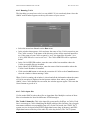
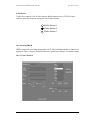
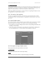
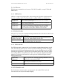
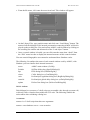
7.1 Mode Of SelFlow Use
The first thing you may be required to do is to run AMOC if it is not yet done. Once the
AMOC main window appears on the top left corner of your screen.
Select the menu item Selflow from Run menu, the Selflow main window will be
opened, as shown in the figure above. In this window you are able to set up the input
files for Selflow. These include the following.
The traffic scenario corresponds to the extension name for traject and crossings files.
The Up/Down Streams correspond to the file containing the definition of the specified
flows.
The DFM button enables you to run a simulation with protection over fixes. You should
turn it on only when fixes are taken into account in the regulation scheme. Once this
button is selected, you must enter the name of the file containing the name of protected
fixes, andthe minimum and maximum levels which apply to an overflying flight subject
to this regulation.
The CFMU button enables you to run a simulation with protection over sectors.
The aerodromes file is the name of the file containing the definition of aerodrome family and the logical operations over flows.
Day of Simulation corresponds to the operational day being simulated. It takes the following format “yymmdd” where “yy” is the year, ‘mm’ is the month and ‘dd” is the
day.
AMOC: ATFM Modelling Capability
32
EUROCONTROL EXPERIMENTAL CENTRE
EEC NOTE No 28 /97
Output file corresponds to the name of a file which will contain the output of SelFlow.
This file will be used by CASA.
Once all the textboxes contain the values you require, you can run SelFlow by clicking
onto “Ok” button or dismiss it by clicking on “Cancel” button.
7.2 Sectors aliases file
The grouping of sectors and aliases file contains attributes describing all grouping of
sectors, including aliases. An alias is an abbreviation of a long name or a preferred
name to the ICAO one. For example, French regulator tend to call the sector “LFMMCO” by the short name “CO”. Also a group of sectors is considered as an alias
because the grouping of a set of adjacent sectors is treated as if the resulting area was a
single sector with geometric boundaries composed of the outermost external boundaries of the individual sectors; The time of piercing of its boundaries is the time of
piercing of the first sector. The alias and the grouping of the adjacent sectors mean,, in
SelFlow context, the same thing and so we will use them interchangeably. SelFlow by
default uses a file called “sec.grp”. So, if you want to add or modify an alias, you
should do it in the sec.grp and save it.
The file has the following format:
<number_of_aliases>
<list_of_aliases>
Examples:
Suppose that we want to use a sector AB as the group of the elementary sectors A and
B. One can define it as follows AB: A B
Suppose again that we want to create the name CO instead of the name LFMMCO.
One can define it as follow CO: LFMMCO
7.3 Aerodromes file
Description: This file contains the definition of all the airport families used in the
flows description and the logical operations on flows. This file is subdivided into two
paragraphs, one paragraph for the definition of the airports families and the second one
for the definition of the logical operations on flows.
Families paragraph: A family is a set of related airports within or outside the simulated area. It consists of a name that uniquely identifies the family and a list of airports.
The format of the families paragraph is as follow:
nb_of_families
family1
nb_of_airports
aiport11
...
...
...
...
...
familyN
nb_of_airports
airportN1
...
AMOC: ATFM Modelling Capability
airport1i
airportNj
33
EUROCONTROL EXPERIMENTAL CENTRE
EEC NOTE No 28 /97
(1) <nb_of_families> is the number of families used in the families paragraph, this
number occupies the first line on the file.
(2) there is a line for a definition of each family, it consists of fields separated by
blank(s):
(2.1) the first field <family> is the name of the family,
(2.2) the second field <nb_of_airports> is the number of airports belonging to the family,
(2.3) a list of airports composing the family.
NB: No blank line is permitted in this families paragraph.
Example: Suppose that in a specified study we are interested in only two airports families. The first family is all the airports within France called FRANC. The second family is all the ‘North Atlantic’ airports called NATS.
The families paragraph will contain the following definitions :
2
FRANC
1
LF**
NATS
7
B***
T***
C***
K***
M***
S***
P***
Logical operations on flows paragraph: A logical operation on two flows consists of
a set of operations stated under the classical form of propositional logic:
• OR operation: It consists of summation of all flights belonging to the two flows.
• AND operation: It consists of selecting only the flights belonging to both flows, This
is important when we are interested in a flow over a segment of routes, or a flow
crossing a sector and overflying a fix.
• Excluding operation: It consists of excluding from one flow another flow. Only the
flights belonging to the first flow and not to the second remain. It’s important when
we want a specified flow crossing a protected volume to be freeflow.
The format of the logical operations paragraph is of the following form:
nb_of_flows
FLOW12
=
FLOW1
op
FLOW2
...
...
...
...
...
FLOWij
=
FLOWi
op
FLOWj
(1) <nb_of_flows> is the number of the logical operations on flows. This number must
be written just after the families paragraph without any blank line. If no logical operations are specified, you must write 0 meaning zero operation.
(2) There is a line for the definition of each operation, it consists of fields separated
with blanks:
(2.1) The first field is the name of the resulting flow,
AMOC: ATFM Modelling Capability
34
EUROCONTROL EXPERIMENTAL CENTRE
EEC NOTE No 28 /97
(2.2) The second field is the mathematical equal sign,
(2.2) The third and the fifth fields are the name of flows defined in the flows file
(explained in the next section),
(2.3) the fourth field is the identifier of the used operation. There are 3 kinds of operations: + for the OR operation, & for AND operation and - for the excluding operation.
Examples
Example1: Suppose that we are interested only in the traffic flowing between two adjacent fixes: fix A and fix B.
In the flows file, you must define two flows: the flow overflying fix A and another flow
overflying fix B. Once these two flows have been defined, you must define the resulting
flow from flowA and flowB as : flowAB = flowA & flowB
This means that SelFlow will first extract the traffic subject to flowA, and traffic subject
to flowB, and afterwards, it will keep only the traffic present in both flows as flowAB.
Example2: Suppose now that we are interested only in the traffic crossing sector SEC
and not overflying fix A.
In the flows file, you must define two flows: the flow overflying fix A and another flow
for the traffic crossing sector SEC. Once these two flows have been defined, you must
define the resulting flow from flowSEC and flowA as : flowSECA = flowSEC - flowA
This means that SelFlow will first extract the traffic subject to flowA, and traffic subject
to flowSEC, and afterwards, it will keep only the traffic present in flowSEC but not in
flowA as flowSEC-A.
7.4 Flows file
This file contains the description of the specified flows. A flow consists of upstream,
downstream elements and a volume. Upstream elements are describing an origin area,
downstream elements are describing a destination area.
An upstream/downstream element can have an exception list which is a set of excluded
airports.
A volume is a set of sectors and/or fixes. A volume is not mandatory but can be present
in the definition of a flow.
You should remember that all the volumes used in the description of a flow are aliases
and should be defined in the aliases file, unless the volume is an elementary sector or a
single fix.
AMOC: ATFM Modelling Capability
35
EUROCONTROL EXPERIMENTAL CENTRE
EEC NOTE No 28 /97
The format of a flow is as follows:
<dep_family>{exception_list}.<arr_family>{exception_list}[^volume]
nb_of_flows
<flow_name1> 1
<start_of_period> <end_of_period>
...
<flow_nameN> 1
<start_of_period> <end_of_period>
(1) The <dep_family>/<arr_family> is the name of a set of airports. The family name
must be defined in the aerodromes file unless it is a single airport, a centre (all airports
belonging to the centre) or a country as whole.
(2) The <exception_list> specifies the set of airports to be excluded from the family of
the airports.
(3) <volume> specifies the part of the airspace to be protected. The volume is not mandatory and if it is not present then the protected area is the dep_family.
(4) nb_of_flows specifies the number of the sub-flows. Suppose that you want to protect a volume from 07:00 to 10:00 and from 12:00 to 18:00. As CASA does not accept
non contiguous intervals, you must define 2 sub-flows, one sub-flow for each interval.
(5) flow_name identifies the name of the flow. This name will be used later as the
name of the CASA regulation.
(6) start_of_period and end_of_period specify the start and end of the activation
period. SelFlow will be used to extract flights whose ETOs fall within this period and
CASA will use this period with a corresponding capacity to allocate slots.
Example1: Suppose we want to regulate all the traffic coming from LFPO, going to
LFMN and crossing the sector UGW between the period 08:00 and 18:00. First, you
must define the flow and give it a name. The name of this flow will be rUGW. The definition for this flow is as follows:
LFPO.LFMN^UGW
1
rUGW 1
480.0 1080.0
The departure and arrival family are single airports so you don’t need to define them in
the aerodrome files. You can if you want but it will be a redundant definition because
SelFlow understands the concept of single airports.
Example2: Suppose that we are interested in departures from FRANCE, going to the
North Atlantic between 18:00 and 20:00. We can see that the only volume of interest
in this abstraction is the departures from the French airports to the North Atlantic
regardless of which sectors are crossed. This flow will be called FRANC>NATS for
departures from France to NATS. Below we show some steps to define this flow:
AMOC: ATFM Modelling Capability
36
EUROCONTROL EXPERIMENTAL CENTRE
EEC NOTE No 28 /97
First, you must describe in the aerodromes file what are the north Atlantic airports, and
what are the French airports. In this paper, we will give to the French airports the global name FRANC, and NATS to the North Atlantic airports.
Second, in the flows file you must define the flow as follows:
FRANC.NATS
1
FRANC>NATS
1
1080.0 1200.0
In the aerodrome files, you will define the two families of airports:
2
FRANC
1
LF**
NATS
7
B***
T***
C***
K***
M***
S***
P***
Explanation: 2 means that the aerodrome file contains two families of airports. Each
line contains the definition of one family of airports which consists of the name of the
family, the number of the elements of the family and the name of each element of the
family in the rest of the line.
Note: It’s better to generate the Flows file with Fred tool. It is a graphical user interface
that allows the creation of the flows and their corresponding regulations. The use of
Fred will be explained later.
7.4.1 Centralised flows
A flow is defined as a centralised flow when upstream and downstream elements are
defined as a whole world and the volume is not present at all or constructed only with
sectors. This definition is generalised even to specialised upstream/downstream
7.4.2 Decentralised flows
A flow is defined as a decentralised flow when the volume contains at least one fix.
7.4.3 Operations on Flows
The discussions with the regulators about flows brought three set of operations stated
under the classical form of propositional logic:
• OR operation: It consists of summation of all flights belonging to the two flows.
• AND operation: It consists of selecting only the flights belonging to both flows, it’s
important when only a flow over a segment of routes, or a flow crossing a sector and
overflying a fix, is in the interest.
• Excluding operation: It consists of excluding from one flow another flow. Only the
flights belonging to the first flow and not to the second remain. It’s important when
we want a specified flow crossing a protected volume to be freeflow.
AMOC: ATFM Modelling Capability
37
EUROCONTROL EXPERIMENTAL CENTRE
EEC NOTE No 28 /97
7.5 Volume
A volume is built from a fix or sector(s). The volume is defined by a single name. It
could be the name of a fix, an elementary sector or an alias. If an alias is used, you must
define it into the alias file unless it’s already done. If a fix is used, you must define it in
the fix file. Here is a description of the way the volume can be defined:
• Fix The location of a point is defined by its latitude and longitude, and by the part
of airspace enclosed between the base altitude and ceiling altitude.
• Sectors The only information needed is the sector name. The sector can be the name
of an elementary sector or an alias.In this case it should be defined in the aliases file.
Example
We want to define a flow comprising traffic crossing the sectors UA, US,
UG1,UG2,UG3,UW1,UW2, UW3. First, we have to define an alias UGWS which is the
parent to all the above elementary sectors. This definition will be put in the alias file
sec.grp; The resulting volume which will be used in the definition of the flow is UGWS.
7.6 Flow Period
A flow period is the interval during which the flights belonging to that flow are
extracted. The extraction is based on the following criteria:
• if the volume is present, a flight is considered to belong to the flow when its departure airport belongs to the flow upstream, and its arrival airport belongs to the flow
downstream, and the time of volume crossing is inside the flow period.
• if the volume is not present (regulation by departure aerodrome), the criteria of
extraction are the same as above, except that a flight is considered to belong to the
flow when its departure time is inside the flow period.
The start and end times of the activation period are expressed in minutes, starting from
the first day of the simulation. To simulate the J day, we usually need the traffic for the
(J-1) day.
The start time simulation for the J day is 1440.0 (= 24 * 60) and the end is 2880.0 (=
24*120).
0.0
(J-1) day
1440.0
(J) day
2880.0
The use of decimal point is for enabling the seconds. You must convert the seconds into
a fraction of minutes.
AMOC: ATFM Modelling Capability
38
EUROCONTROL EXPERIMENTAL CENTRE
EEC NOTE No 28 /97
7.7 Fix file
This file is used only when one of the protected volumes is, or contains a fix. The format of the file is very simple:
fix_name
latitude longitude floor
ceiling
Example: MOPUG needs to be protected between FL070 to 250, and from FL250 to
unlimited. Two differents points have to be created:
MOPUG1
461000 -0204200 70.0 250.0
MOPUG2
461000 -0204200 250.0 999.0
7.8 Traffic file and how it is processed
SelFlow reads two files from the same directory: For fix based regulations, it uses the
traject file that contains the routes of scheduled traffic in 4 D format (latitude, longitude, altitude and ETO). For sectors based regulations or airport based regulations, SelFlow uses the crossings file which contains information about the crossed sectors and
the time estimated over. Both files are generated by ATAC module from the
ALL_FLIGHT file for a defined operational day.
You must remember that both files contain information about the traffic for two days:
the previous day and the day of the simulation. Thus, the simulation time lasts from 0
minute to 2880 minutes:
(1) The traffic corresponding to the previous day starts at 0 min. and ends at 1440 min,
(2) and the traffic for the operational day starts at 1440 min and ends at 2880 min.
The need to have both the previous day and the operational day is to take into account
the flights departing the previous day and arriving on the operational day.
7.8.1 Traject file
Descriptions: This file contains the climb/cruise/descent profiles for all the simulated
flights. It includes the ETO and altitude at each overflown fix.
Data Record 1: Aircraft Information.
Column
Format
Contents
1-5
Integer
Aircraft identifier
6-8
Alpha
Aircraft operator
9-12
Alpha
Aircraft type
13-13
Integer
Equipment category
14-14
Integer
Enroute time category
16-17
Integer
Number of legs
AMOC: ATFM Modelling Capability
39
EUROCONTROL EXPERIMENTAL CENTRE
EEC NOTE No 28 /97
Data Record 2 : Airports Information. This record describes the departure and arrival
airports, plus the time of departure and arrival, and the ground delay incurred by the
flight. This record is repeated Number_of_legs time.
Column
Format
Contents
1-5
Alpha
flight ID
6-9
Alpha
Departure Airport
11-14
Alpha
Arrival Airport
15-22
Real
Departure Aiport latitude (decimal degree)
24-31
Real
Departure Airport longitude(decimal degree)
33-36
Integer
Departure time (in minute)
37-44
Real
Arrival Airport latitude (decimal degree)
46-53
Real
Arrival Airport longitude (decimal degree)
55-58
Integer
Arrival time (in minute)
62-63
Integer
Delay (in minutes)
66-68
Integer
Azimuth
70
Char
Direction
72
Char
Flight Plan Completeness
75-76
Integer
Number of fixes in the route
Data Record 3: Routes Information. This record describes the route that links the two
airports. This record is repeated Number_of_fixes time.
Column
Format
Contents
1-2
Alpha
Always RP
3-7
Alpha
Fix name
8-15
Real
Fix latitude (decimal degree)
17-24
Real
Fix longitude (decimal degree)
26-28
Integer
Fix altitude
30-37
Real
Estimated Time Over
7.8.2 Crossings file
Descriptions: This file contains the crossed sectors for all the simulated flights. It
includes the ETO for each crossed sector. The information here is the same as that used
in the traject file
Data Record 1: Aircraft Information
Column
Format
Contents
1-5
Integer
Aircraft identifier
6-8
Alpha
Aircraft operator
9-12
Alpha
Aircraft type
13-13
Integer
Equipment category
14-14
Integer
Enroute time category
16-17
Integer
Number of legs
AMOC: ATFM Modelling Capability
40
EUROCONTROL EXPERIMENTAL CENTRE
EEC NOTE No 28 /97
Data Record 2 : Airports Information. This record is repeated Number_of_legs time. It
describes the departure and arrival airports, plus the time of departure and arrival, and
the ground delay incurred by the flight. It is slightly different from the Data Record 2
describe in the traject file.
Column
Format
Contents
1-5
Alpha
flight ID
6-9
Alpha
Departure Airport
12-15
Integer
Departure time (in minute)
16-19
Alpha
Arrival Aiport
22-25
Integer
Arrival time (in minute)
29-30
Integer
Delay (in minute)
33-35
Integer
Azimuth
36
Char
Direction
37-38
Integer
Number of crossed sectors
Data Record 3: Sectors Information. This record describes the en-route sectors. This
record is repeated Number_of_crossed_sectors time.
Column
Format
Contents
1-2
Alpha
Always SC
3-8
Alpha
Sector name
9-14
Real
Estimated Time Over (in minute)
16-20
Real
Flying time in the sector (in minute)
22-26
Real
Flying time to the next sector or ades
7.8.3 Processing
SelFlow reads the traffic file into memory and compares each flight to the appropriate
flow, then either stores the flight in the output file in a format readable by CASA or discards it. A flight belongs to a flow only if:
• the departure airports is in the list of the departure families, AND
• does not belong to the list of the departure exceptions, AND
• the arrival airports is in the list of the arrival families, AND
• does not belong to the list of arrival exceptions, AND
• there is a common airspace between the list of fixes or sectors crossed by the flights
and the flow volume, AND
• the expected time over the common airspace is after the start time and before the
stop time of the flow. For reasons related to the inability of the CASA version 1.4 to
deal with the collapsed sectors, the start time of each flow is adjusted to 1 hour
before flow start time, and the stop time one hour after flow stop time automatically
by SelFlow.
You should also remember that the maximum of the regulations one flight can be subject to is limited to 10 regulations in CASA mode Simca and 15 in CASA mode
TACOT.
AMOC: ATFM Modelling Capability
41
EUROCONTROL EXPERIMENTAL CENTRE
EEC NOTE No 28 /97
7.9 Statistics
SelFlow generates hourly statistics about all the defined flows. These statistics are used
later to determine for which period of the day a flow needs to be regulated. The statistics are not limited to elementary sectors but are extended to any kind of volumes:
- Departure airports
- Departure/Arrival airports
- Family of departure/arrival airports
- Segment of a route
- Navaids
- Groups of sectors
Example: Below, are hourly statistics for global movement (departures and arrivals) in
some European airports.
The field separator is colon “:” , thus you can process the statistics file with Excel for
producing charts.
Flows
Hourly distribution from 0 to 23
LEMDGLO:
6 : 7: 5: 2:14:38:53:55:59:47:44:36:45:37:33:46:50:51:53:48:34:24: 5: 5
LEPAGLO:
6 : 7: 7: 7:10:34:28:33:23:17:20:21:33:21:18:26:29:24:44:30:29:18:11:10
LGTSGLO:
1 : 1: 1: 2: 3: 5: 7:12: 7: 5:11:10: 7: 9: 9:10: 7: 5: 1: 5: 5: 2: 2: 2
LGATGLO:
3: 5: 9:19:14:30:35:29:25:25:25:21:38:26:34:25:19:24:16:11:12: 7: 3: 2
LGIRGLO:
3: 1: 0: 1: 2: 2: 7: 6:14: 6: 7: 7: 6: 7: 9:11:10:10:14: 5: 5: 6: 3: 7
EBBRGLO:
3:14:13: 1:10:36:58:47:71:36:36:55:33:49:35:49:51:64:43:32:25:13:20: 5
EDDBGLO:
3: 2: 2: 6: 6: 5: 3: 5: 7: 4:11:11: 6: 5: 6: 4: 2: 4: 2: 6: 6: 3: 5: 7
7.10 Log file
This file contains valuable information that can be used to link the flights regulated by
CASA and their origin-destination. Thus, statistics modules can be coded for example
to produce total delay per departure aerodrome, arrival aerodrome or both. The traffic
volume file sent to CASA does not contain the city pair for the regulated flights.
Column
1st column
2nd column
3rd column
4th column
5th column
6th column
Format
Integer
Alpha
Alpha
Integer
Alpha
Integer
AMOC: ATFM Modelling Capability
Contents
Aircraft ID
Call sign
Departure airport
Departure time
Arrival airport
Arrival time
42
EUROCONTROL EXPERIMENTAL CENTRE
Column
7th column
8th column
Format
Alpha
Integer
EEC NOTE No 28 /97
Contents
Regulation ID
ETO
NB: the 7th and 8th columns can be repeated if there are other regulations
.
AMOC: ATFM Modelling Capability
43
EUROCONTROL EXPERIMENTAL CENTRE
EEC NOTE No 28 /97
INTENTIONALLY LEFT BLANK
AMOC: ATFM Modelling Capability
44
EUROCONTROL EXPERIMENTAL CENTRE
EEC NOTE No 28 /97
8.0 DeliverCtot
The output of CASA is a very large trace file that contains valuable information. This
information concerns the creation of the regulation, the allocation of slot for each flight
and all the updates.
The purpose of DeliverCtot is to extract the calculated take-off times (CTOT) from this
file and inject them into traject and crossings files. It stands downstream from CASA
and upstream from SelFlow.
8.1 Running DeliverCtot
The first thing you may be required to do is to run AMOC if it is not yet done. Once the
AMOC main window appears on the top left corner of your screen:
• Select the menu item DeliverCtot from the Run menu.
• Enter the CASA Server. By default, the casa server is mahler; and you should modify it if the CASA executable files and scenarios are placed elsewhere.
• In the window that appears, click and enter the name of the CASA scenario, and the
extension for the traffic file (traject and crossings files to be updated).
• Click onto the Ok button to activate the execution of DeliverCtot or Cancel button
to close the window without running DeliverCtot.
When DeliverCtot is running, the window is closed and all the information about the
status of DeliverCtot execution is displayed on the hpterm window from which you
have launched AMOC. Once DeliverCtot finishes its execution, the window appears
again. Click onto the cancel button to get rid of it. If no problems are encountered during execution, DeliverCtot will produce new traffic files: crossings.<new_extension>
and traject.<new_extension>
8.2 Input
The CASA output file used by this program is called “temp”, so the pathname used by
DeliverCtot to access this file is “/net/casa-server/users/casa/casa07/casa_scenario”. At
the time being the casa-server is “mahler”. The program extracts the lines of this file
AMOC: ATFM Modelling Capability
45
EUROCONTROL EXPERIMENTAL CENTRE
EEC NOTE No 28 /97
that are relevant to generation of CTOTs, and stores the information by flight. The
CASA output file may contain many CTOT messages per flight, in such case only the
last CTOT is taken into account. Two other files are used by DeliverCtot are crossings.<extension> and traject.<extension>
8.3 Output
The output of the program is the traffic file (traject and crossings files) that differs from
the original only by having the departure times generated by CASA. DeliverCtot
applies the delay occurred by a defined flight to all the resources used by that flight
(fixes, sectors)
IMPORTANT: The traject.<new_extension> and crossings.<new_extension> must be
injected again into SelFlow to show the effect of the ATFM measures on non-regulated
parts of the airspace.
IMPORTANT: If all the sectors were regulated, then there is no need to run DeliverCtot
because CASA takes care of smoothing the traffic in all the protected area.
IMPORTANT: The <new_extension> is equal to <extension_update>. If the original
traffic files are crossings.1996 and traject.1996, then the new updated traffic files are
crossings.1996_update and traject.1996_update.
8.4 How DeliverCtot processes
DeliverCtot reads from temp file the delays generated by CASA and uses the aircraft id
and leg id extracted from this file to find the flight to which the delay must be injected.
The DeliverCtot changes the times in flight header and course points and outputs the
updates into two new traffic files: crossings.<originalextension_update> and traject.<originalextension_update>.
AMOC: ATFM Modelling Capability
46
EUROCONTROL EXPERIMENTAL CENTRE
EEC NOTE No 28 /97
9.0 PerfAnalysis
Performance analysis (PerfAnalysis) module is developed to extract key output metrics from CASA reports. This module measures the performance of ATFM strategies
applied on a defined traffic with a defined airspace configuration in terms of:
• Total Ground Delay
• Average regulated flights
• Average constrained flights
• Maximum delay
• Number of regulated flights
• Number of constrained flights
• Number of flights with delay greater than one hour
• Number of flights with delay between half an hour and one hour
• Number of flighs with delay less than 15 minutes
• And for each regulation:
1. The total delay imposed by that regulation
2. The number of unused slots
3. The number of overloaded slots
These key output metrics enable the regulators to: choose the ATFM strategy that best
fits the traffic and the airspace configuration; to adjust the ATFM measures in order to
diminish the number of combined flights; or to remove the redundant regulations (protected upstream/downstream by others regulations).
9.1 Running PerfAnalysis
From the AMOC main window:
• Select the menu item “Performance Analysis” from the Run menu
• In the window that appears, click and enter the name of the CASA scenario to be
analysed.
• Click onto the Ok button to activate the PerfAnalysis or Cancel button to close the
window.
Once the Ok button is activated, all the information concerning the ATFM key measures (described above) is summarized on the window. Another window appears that
contains information concerning the regulations. A simple click on the name of the regulation gives the key metrics for the clicked on regulation.
AMOC: ATFM Modelling Capability
47
EUROCONTROL EXPERIMENTAL CENTRE
EEC NOTE No 28 /97
CAUTION: You must not try to execute PerfAnalysis on a CASA scenario that is not
already executed by CASA because PerfAnalysis reads from the output of CASA.
AMOC: ATFM Modelling Capability
48
EUROCONTROL EXPERIMENTAL CENTRE
EEC NOTE No 28 /97
9.2 Input
PerfAnalysis uses the report files generated by CASA. There is a report for each regulation. The program extracts the lines of these files that are relevant to the regulation,
and displays the key metric measures by regulation in the dedicated text boxes.
9.3 Output
The output of PerfAnalysis is displayed directly on two windows:
Scenario Performance metrics window contains global information about the ATFM
strategy: total delay; average regulated and constrained flights; maximum delay;
number of regulated and delayed flights; number of flights with delay greater than one
hour; between half an hour and one hour and less than 15 minutes.
AMOC: ATFM Modelling Capability
49
EUROCONTROL EXPERIMENTAL CENTRE
EEC NOTE No 28 /97
INTENTIONALLY LEFT BLANK
AMOC: ATFM Modelling Capability
50
EUROCONTROL EXPERIMENTAL CENTRE
EEC NOTE No 28 /97
10.0 FRED
The Flows and Regulations EDitor (FRED) tool is a graphical interface that enables the
description of a regulation schema into flows description and their corresponding regulations.
Flows and Regulations EDitor FRED is developed to meet the following objectives:
• simplify the process of creating the flows,
• offer a way to describe in detail the flows (sample definition, complex definition by
cutting the natural description into the logical operations between flows),
• enforce the CASA regulations on one or several created flows,
• propagate the flow attributes (identifier, time period of activation) to the attached
CASA regulation,
• tailor the CASA regulations attributes (sub-periods and their applied hourly rates),
• save, in the appropriate location, a newly created scenario,
• load a previously saved scenario, and modify it as needed.
As shown above in the section SelFlow, flows and regulations are inter-dependent:
• Flows describe the upstream/downstream and the controlled zone,
• while CASA regulations enforce the ATFM measures for the flow under consideration.
10.0.1 Purpose of FRED
Flows and Regulations EDitor (FRED) is an interactive display and data generation
tool that can be used to create flows and CASA regulations and to generate data files
describing flows and regulations. The flows and Regulations can be modified, if necessary, and fed back into SelFlow and CASA.
The FRED tool is written in Modsim, Object-Oriented language , and uses a run-time
graphics library called Simgraphics. In addition, several modules format data for input
to FRED and convert the output from FRED for input into SelFlow and CASA.
AMOC: ATFM Modelling Capability
51
EUROCONTROL EXPERIMENTAL CENTRE
SELFLOW
EEC NOTE No 28 /97
flo
ws
FRED
CASA
s
on
ti
ula
reg
Regulations plan
FIGURE 1. FRED Data Flow Diagram
10.1 Controls of FRED
The intention of the FRED design is to balance the three goals of simplicity, consistency, and efficiency:
• the FRED system is based on a simple interface,
• the FRED system is easy to learn, and users can get work done right away,
• when you perform a new task, you can later update it with minimal effort,
The FRED system uses few and simple controls to accept events or trigger an action.
The controls which FRED uses are discussed below.
AMOC: ATFM Modelling Capability
52
EUROCONTROL EXPERIMENTAL CENTRE
EEC NOTE No 28 /97
1. Button
A button is used to receive a simple input event. Clicking on a button with the mouse
will execute an action.
Button
2. Text Box
A text box is used to receive a string of characters. The text box must be selected before
entering text.
Text Box
LFPG LFPO LFPV LFPB
3. List Box
A list box is used to select an item from a list of items.
ITEM1
ITEM2
ITEM3
ITEM4
AMOC: ATFM Modelling Capability
53
EUROCONTROL EXPERIMENTAL CENTRE
EEC NOTE No 28 /97
4. Radio box
A radio box contains a list of radio buttons. Radio buttons receive YES/NO input
which is mutually exclusive among the list of radio buttons.
Radio Button 1
Radio Button 2
Radio Button 3
10.2 Starting FRED
FRED is started by executing the program “fred”. After initialisation three windows are
displayed, Flows, Airports Families and Flows Operations windows are initially empty.
10.2.1 Flows Window
AMOC: ATFM Modelling Capability
54
EUROCONTROL EXPERIMENTAL CENTRE
EEC NOTE No 28 /97
The Flows window holds flows being created or loaded from a previously saved scenario.
• New flows can be constructed in the create mode by entering the information in the
appropriate boxes and clicking the button “Add” to insert the flow in the list of
flows.
• In the select mode, the information concerning the selected flow is displayed in the
corresponding box. A selected flow can be updated , removed , and CASA regulations can be assigned or cancelled from selected flows.
When all the flows and regulations are entered with FRED, the scenario can be saved,
information about the scenario can be printed or displayed eg: number of flows,
number of flows operations, number of Airports Families and number of CASA regulation.
10.2.2 Description of Flows window
This window allows flows objects to be edited.
1. Flow Name
A text box to specify the name of the flow.
2. FROM
A text box to specify the departure airport family.
3. EXCEPT
A text box to specify the departure airport exception from the family list, if any.
4. TO
A text box to specify the arrival airport family.
5. EXCEPT
A text box to specify the arrival airport exception from the family list, if any.
6. VIA
If checked, permits to enter the volume under consideration.
7. START
A text box to specify the start time of the flow in hours and minutes (HHMM). To specify the day of the start time, click on the Radio Box:
• J-1 : Previous day
• J
: Tactical day
• J+1 : Next day
AMOC: ATFM Modelling Capability
55
EUROCONTROL EXPERIMENTAL CENTRE
EEC NOTE No 28 /97
8. END
A text box to specify the end time of the flow in hours and minutes. To specify the day
of the end time, click on the Radio Box:
• J-1 : Previous day
• J
: Tactical day
• J+1 : Next day
10.2.3 Creating a flow
When all the above information is entered, click on “Add” button to create the flow.
10.2.4 Updating a flow
To update a flow, the following steps must be respected:
• from the list box, select the flow to be updated. All the informations concerning the
flow are displayed in their correspondent widgets
• modify the informations concerning the selected flow.
• click on the button “Update”
10.2.5 Remove a flow
To remove a flow, the following steps must be respected:
• from the list box, select the flow to be removed
• if a CASA regulation is attached to the flow, remove it by clicking on “Delete
CASA” button
• click on “Remove” button to destroy the flow
AMOC: ATFM Modelling Capability
56
EUROCONTROL EXPERIMENTAL CENTRE
EEC NOTE No 28 /97
10.2.6 Attach CASA regulation to a flow
• Before trying to attach a CASA regulation to a flow, the flow must exist in the list
box and be selected. After clicking on “Edit CASA” button, the following window
is displayed:
If a CASA regulation has been assigned to the flow, the window will contain all the
information concerning the regulation (as it is shown in the above window), and all
modifications will be automatically saved. Otherwise, the window will be empty
except for the regulation ID, start time and end time that are inherited directly from the
flow, plus a new button “Accept Regul”.
Each CASA regulation is identified with:
• a regulation ID which is the same as the flow name
• and a list of contiguous sub-periods with their corresponding capacities
Three modes of operations are used:
• Adding sub-periods
a sub-period is identified by a start time, end time and capacity. First enter the start, end
time and capacity and click on “Add Sb Period” button to insert the newly created subperiods in the list of sub-periods box.
• Remove sub-periods
click on the list of sub-periods box to select the period, and click on “Remove Sb Periods” to remove it. The removal of sub-period has a chain reaction because the update
is transferred to the previous or next sub-period. If the sub-period is at the top of the
list box, the update is transferred to the next sub-period, and in the other case, the transmission is reverse.
AMOC: ATFM Modelling Capability
57
EUROCONTROL EXPERIMENTAL CENTRE
EEC NOTE No 28 /97
• Update sub-periods
Click on the list of sub-periods box to select the period, make your change in the corresponding boxes and save your change by clicking on “Update Sb Period” button. The
update of a sub-period has, as in the case of removal, a chain reaction.
When the regulation sub-periods are created, click on “Accept Regul” button to create
the regulation or on “Quit” button to cancel.
10.2.7 De-attach a CASA regulation
To remove a regulation from a flow, select the flow concerned and click on “Delete
CASA” button. There is no undo button, if a regulation is removed, there is no way to
get it back.
10.3 Airport Families window
The Airports Families window holds the airports families under construction or loaded
from a previously saved scenario. Two modes are used creating and selecting
• New families are created by filling each box with its corresponding information, and
clicking on “Add” button
• In the select mode, the information concerning the selected family is displayed in
the corresponding boxes. A selected family can be updated or removed.
10.3.1 Description Of Airport Families window
This window allows the airport families to be edited.
1. Family Name
A text box to specify the name of the airport family.
2. NB
A text box to specify the number of airports belonging to this family.
AMOC: ATFM Modelling Capability
58
EUROCONTROL EXPERIMENTAL CENTRE
EEC NOTE No 28 /97
3. Airports
A text box to specify the airports composing the family.
10.3.2 Creating an airport family
Once the above text boxes have been filled with corresponding information, click on
“Add” Button to create the airport family.
10.3.3 Updating an airport family
To update an airport family, the following steps must be respected:
• Select first from the list box, the family to be updated. All the informations concerning the family are displayed in their correspondent boxes.
• modify the information concerning the selected family.
• click on the button “Update”.
10.3.4 Remove an airport family
To remove a family, the following steps must be respected:
• Select first from the list box, the family to be removed.
• Be sure that this family is not part of a flow scope.
• click on “Remove” button to destroy the family.
10.4 Flows Operations window
The flows operation window holds operations on flows under construction or loaded
from a previously saved scenario. Two modes of operations are used; creating and
selecting:
• A flow can be created from two previously created flows and its type of operation
specified. Three operations are used: Exclusive, Inclusive and And operations(see
SelFlow section for explanation).
AMOC: ATFM Modelling Capability
59
EUROCONTROL EXPERIMENTAL CENTRE
EEC NOTE No 28 /97
• A selected flow can be updated or removed
10.4.1 Description of the flows logical operations window
This window allows an operation on a flow to be edited
1. Flow Name
A text box to specify the name of the resultant flow.
2. Flow1
A text box to specify the name of the first flow.
3. Flow2
A text box to specify the name of the second flow.
AMOC: ATFM Modelling Capability
60
EUROCONTROL EXPERIMENTAL CENTRE
EEC NOTE No 28 /97
4. Radio Box
This Radio Box allows you to specify the type of the operation between the first and
second flow to produce the resultant flow (see SelFlow ):
• Inclusive
• Exclusive
• And
10.4.2 Creating an operation on flows
Once all the above informations is entered, click on “Add” Button to create the operation. You must be sure that the first and second flow are well defined using the Flows
window. The creation of a resultant flow is not recursive: A resultant flow cannot be
used to define another resultant flow.
10.4.3 Updating an operation on flows
To update an operation, the following steps must be respected:
• from the list box select the flow to be updated. All the information concerning the
flow is displayed in its corresponding boxes.
• modify the information concerning the selected flow.
• click on the button “Update”.
10.4.4 Remove an operation on flows
To remove an operation, the following steps must be respected:
• first from the list box, select the flow to be removed.
• click on “Remove” button to destroy the flow.
10.5 Save a scenario with FRED
Once all the flows, airport families, operations on flows and the CASA regulations have
been created, you can save your scenario by:
• Typing the name of your scenario on the text box “scenario”.
• Clicking on the “save” Button.
If your scenario already exists, a window will be displayed to ask you if you want to
overwrite or rename it.
10.6 Load a scenario with FRED
Scenarios can be loaded into FRED and edited. To do this, type the name of the scenario in the “scenario” text box and click on “load” Button.
AMOC: ATFM Modelling Capability
61
EUROCONTROL EXPERIMENTAL CENTRE
EEC NOTE No 28 /97
10.7 Information about a current scenario
FRED allows you to know the number of flows, airport families, operation on flows
and the attached CASA regulation. Simply, click on the “info” Button.
10.8 Exiting FRED
Selecting “Return from FRED” Button exits FRED. Any objects which have not been
saved will not be lost: FRED will ask you if you want to save them or not.
AMOC: ATFM Modelling Capability
62
EUROCONTROL EXPERIMENTAL CENTRE
EEC NOTE No 28 /97
11.0 ATAC (Airspace Traffic dAta Capture)
11.1 Objective
The Airspace Traffic dAta Capture, ATAC, is a data generation tool permitting the creation of crossings and traject files from the CFMU traffic.
TACT oplog
file
URS_TOOL
ALL_FLIGHT
country code
eqpmcats
fix locations
ATAC
crossings
file
traject
file
FIGURE 2. ATAC Data Flow Diagram
11.2 ATAC Module
The ATAC module is used to process the ALL_FLIGHT file for a specified operational
day and produces files used by SelFlow: crossings and traject files.
11.2.1 Output files
1. crossings.<suffix>
This file contains the scheduled flight plans of the simulated day. For each
flight, a description of the en-route sectors used is given. A full description
AMOC: ATFM Modelling Capability
63
EUROCONTROL EXPERIMENTAL CENTRE
EEC NOTE No 28 /97
of this file is given in the SelFlow section.
2. traject.<suffix>
This file describes a 4 dimensional route for each flight. A full description
of this file is given in the SelFlow section.
11.2.2 Input files
1. ALL_FLIGHT file
The traffic file contains the following data for each flight : departure airport, arrival airport, flight id, air carrier, aircraft type, departure date and time, flight number, flight
level, followed by route (time, fix).
2. faaoag_locid_lalo.<suffix>
This file contains the fixes and airports coordinates (latitude and longitude). The
CFMU traffic file records give only the fixes and airports location indicators.
3. eqpmcats
For each aircraft type this file contains the turnaround time category, the en-route time
category, and the climb/descent profile.
4. country code
The country code file contains abbreviations of the ICAO names. The first two characters are replaced by a single character. This file is used because sector names are coded
with 6 characters, while the CFMU sector names are coded with seven characters.
AMOC: ATFM Modelling Capability
64
EUROCONTROL EXPERIMENTAL CENTRE
EEC NOTE No 28 /97
12.0 Flight Increase Processor Software
The Flight Increase Processor Software (FIPS) generates additional flight demand for
simulation studies. The flight demand is comprised of aircraft itineraries. An itinerary
is a series of connected flight legs for a given aircraft. A flight leg is specified by a
departure airport and arrival airport, an estimated departure time and an estimated
arrival time. The Flight Increase Processor Software program generates aircraft itineraries according to selection criteria and assigns a four-dimensional trajectory and a list
of en-route sectors to each leg. This demand reflects predicted changes for a specified
future day. It is used for modeling future scenarios.
The Flight Increase Processor Software generates flights so that the hourly distribution
of traffic demand is uniformly distributed over all the resources (airports, sectors,
flows ...).
crossings
traject
SelItin
itineraries
statfor
Forecast
additional
itineraries
FIRST
new crossings
AMOC: ATFM Modelling Capability
new traject
65
EUROCONTROL EXPERIMENTAL CENTRE
EEC NOTE No 28 /97
12.1 input files
1) Traffic
The original traffic is composed of two files: crossings file and traject file. A full
description of the format of those two files is given in the section SelFlow.
2) The predicted growth file
The growth file contains the DED4 prediction about the increase of traffic. This
increase concerns origin and destination pattern. The format of this file is a series of
origin-destination of interest and the percentage of the flights to be generated for that
pattern:
origin1;destination1;rate1
...
originN;destinationN;rateN
Each origin-destination is of the form:
airport11+airport12+ ...+airport1N-airport21-...-airport2i
The ‘+’ sign means that the airport is part of the flow and the ‘-’ sign means that the airport is excluded from the flow.
Example: C***+K**+PA**;EK**-EKVG;15
This line means that all departures from Canada, USA and Alaska arriving to Denmark
except FAROE islands must be increased by 15%.
12.2 Ouput files
The Flight Increase Processor Software produces two output files:
• crossings file named as <crossings.orig.inc>
• and traject file anmed as <crossings.orig.inc>.
Both contain the original flights plus the newly generated ones.
12.3 Processing
The predicted growth is specified in an input file prepared by DED4 (STATFOR). The
STATFOR file contains flows and their predicted growth rates. The Flight Increase
Processor Software uses that file to drive the creation of new demand. The Flight
Increase Processor Software consists of three separate tools:
• The Itineraries Selector (SelItin) script program extracts the aircraft itineraries from
the original traffic file (crossings and traject files) and its output is an intermediate
file containing the aircraft itineraries.
• The Forecast program reads statfor and the intermediate itineraries files and generates an output file containing the additional itineraries for the extra flights. For each
individual flow read from statfor, the Forecast program extracts , randomly, (
AMOC: ATFM Modelling Capability
66
EUROCONTROL EXPERIMENTAL CENTRE
EEC NOTE No 28 /97
rate*nb_of_flights_on_the_flow)/100 flights from the intermidiate itineraries file,
and for each extracted flight a departure time is assigned randomly within the operational day.
• The Fast Insertion Routes and Sectors Tool (FIRST) uses the aircraft id to assign a
four-dimensional trajectory and a list of en-route sectors to each extra flight. The
times are the original times over resources plus the difference between the randomly
assigned ETOT and the original ETOT.
The Flight Increase Processor Software (FIPS) is a C-shell script that controls the execution of the three separate tools. The following flow data diagram describes the way
FIPS generates additional flights from the DED4 figures and the original traffic files.
12.4 Running FIPS
From the AMOC main window:
• Select the menu item “Flight Increase Processor” from the Run menu
• In the window that appears, click and enter the name of the traffic scenario to be
increased.
• Enter the name of the STATFOR file containing the DED4 growth forecast.
• Click the Ok button to activate the FIPS or Cancel button to close the window.
AMOC: ATFM Modelling Capability
67
EUROCONTROL EXPERIMENTAL CENTRE
EEC NOTE No 28 /97
INTENTIONALLY LEFT BLANK
AMOC: ATFM Modelling Capability
68
EUROCONTROL EXPERIMENTAL CENTRE
EEC NOTE No 28 /97
13.0 The graphical User Interface of AMOC
The graphical user interface for AMOC consists of a series of dialogue boxes and
menus. From the AMOC main window, all the AMOC modules can be activated and
run through their own dialogue boxes as explained in the previous sections. The
AMOC GUI is coded with Simgraphics. The look and feel is of X11/Motif.
All the code of AMOC GUI is on the files DGui.mod and IGui.mod. The IGui module loads the control windows from a file called “graphics.amoc” located in the bin
directory.
To edit the AMOC GUI file , you can use Simdraw. The process of editing is as follows:
• Change the current working directory to “bin” directory where the graphics.amoc
file is kept.
• Type the following command: simdraw.
• From the file menu, click onto the menu item load. The following window will
appear.
• On the Library Files, type graphics.amoc and click the “Load library” button. The
names of all the control windows comprising AMOC will be displayed on the
scrolling list. You can load any AMOC control window by clicking on the scrolling
list window and afterwards on the “Load object” button.
• Once a control window is loaded, you can click onto the menu item “detail” from
the “Edit” menu in order to display the internal structure of this control window.
The purpose of this section is not to give a full description of Simdraw. You can consult
Simgraphics users manual to fully understand how Simdraw works.
AMOC: ATFM Modelling Capability
69
EUROCONTROL EXPERIMENTAL CENTRE
EEC NOTE No 28 /97
The following outline lists the names of all control windows used by AMOC. With
Simdraw you can visualise their internal structures:
menu
Prelude
fips
simca
rwin
statwin1
update
AMOC main window
SelFlow dialog box
FIPS dialog box
CASA dialog box
PerfAnalysis regulation dialog box
PerfAnalysis global delay dialog box
DeliverCtot dialog box
The graphical user interface for FRED is in a separate file located on FRED home
directory. The name of this file is graphics.fred.
AMOC: ATFM Modelling Capability
70
EUROCONTROL EXPERIMENTAL CENTRE
EEC NOTE No 28 /97
14.0 AMOC Advanced Features
The rest of this paper is intended for the software engineers who will maintain the
AMOC Simulator. It is written for users who have basic computer skills such as managing files and using UNIX commands. All users are expected to be familiar with Modsim, Simgraphics and Simdraw. Be sure to consult documents about those languages.
14.1 AMOC Installation Instructions From a tape
The following steps outline the installation procedures of AMOC from a tape:
1. Create the AMOC “home” directory. The Unix script files that run the software provided on the tape assume that the home directory for AMOC is under “$home” directory.
2. Set the current directory to AMOC home directory and insert the tape in the tape
drive. From the UNIX command line type:
tar xvf /dev/<tape device> , where <tape device> is usually rst0. If you have any
doubt contact your System Administration.
This command will automatically copy the AMOC subdirectories under the AMOC
home directory.
3. Under AMOC home directory, create a link to the CASA location directory. From
the UNIX command line type:
ln -s <casa-location> CASA
After the AMOC files have been copied from the tape, the .cshrc file needs to be modified to contain AMOC environment settings:
setenv
setenv
setenv
setenv
setenv
AMOC
FRED
DATAIN
DATAOUT
casa
$home/AMOC
$AMOC/FRED
$AMOC/data/in
$AMOC/data/out
/net/mahler/users/casa/casa07
4. You should add the AMOC bin directory to the environment variable path. Edit your
.cshrc file, and type at the end of this file the following line:
set path=($AMOC/bin $path)
5. Set the current directory to AMOC src directory and edit the mscomp.cfg file. This
file is necessary to compile with Modsim. The mscomp.cfg file must contains the following lines:
1.9.13 ‘- Version of ‘mscomp’ and MODSIM II Compiler
MSEXEC> /usr/modsim1.9.13/bin ‘- MODSIM II system directory
MSLIB> /usr/modsim1.9.13/lib/modsim ‘- MODSIM II library/import directory(s)
DEF> . ‘- Definition source module directory
AMOC: ATFM Modelling Capability
71
EUROCONTROL EXPERIMENTAL CENTRE
EEC NOTE No 28 /97
IMP> . ‘- Implementation source module directory
OBJ> . ‘- Object file directory
SR> ON ‘- Subrange and subscript checking
PTR> ON ‘- Pointer checking
REF> ON ‘- Reference variable checking
TB> ON ‘- Runtime error traceback
OM> OFF ‘- Generate Object Mgr info
DEBUG> OFF ‘- Generate debugger code
GRA> ON ‘- Link with graphics library
3D> OFF ‘- Link with 3D graphics library
SO> OFF ‘- Link with SimObject library
LIS> OFF ‘- Generate compilation listing
ERR> OFF ‘- Keep .err files, if any
BEEP> ON ‘- Audible prompts
14.2 AMOC Installations Instructions From a tar file
The Installation instructions from a tar file are the same as the installation instructions
from a tape. The only change occur at the step 2:
1. The same instruction as before,
2. Log to the server containing AMOC home directory. Under AMOC home directory
residing in this server, type the following commands:
tar cvf tarfile .
compress tarfile
exit
2-1. Ftp to the server containing the tarfile and type the following commands from the
ftp prompt:
binary
get tarfile.Z
quit
2-2. From your local workstation, type the following commands:
uncompress tarfile.Z
tar xvf tarfile
3. The same instruction as before.
4. The same instruction as before.
5. The same instruction as before.
AMOC: ATFM Modelling Capability
72
EUROCONTROL EXPERIMENTAL CENTRE
EEC NOTE No 28 /97
14.3 Directory Descriptions
The following outline shows the AMOC directory structure. Each directory has a
README file that contains information about the directory and its contents. The information in the README files is more current than in the printed manuals. The AMOC
directory structure is shown below; Note that individual files are not listed.
AMOC
FRED
CASA
bin
src
com
data
in
out
The contents of the AMOC directories and significant files are summarized below:
bin
com
src
FRED
CASA
data/in
data/out
AMOC programs and Simgraphics graphical user interface files
C-shell scripts including DeliverCtot, FIPS, SelItin
AMOC source code, except for FRED and CASA
FRED source code
virtual link to the location where CASA executables and scenarios
are located
input files to SelFlow, FIPS, DeliverCtot, STAIR and ATAC
output files of SelFlow.
AMOC: ATFM Modelling Capability
73
EUROCONTROL EXPERIMENTAL CENTRE
EEC NOTE No 28 /97
14.4 src directory
This directory contains the code source of all AMOC modules, except CASA and
FRED codes.
14.4.1 SelFlow files
SelFlow is composed of include files (files starting with D) and the implementation
files (files starting with I). The files needed to compile SelFlow are listed below:
DFlight2.mod,
IFlight2.mod
They represent the definition and implementation source modules of
Objects used to process flights.
DRegul3.mod,
IRegul3.mod
They represent the definition and implementation source module of
Objects used to process flows.
Dselflow.mod,
They represent the definition and implementation source modules of
the Object “Task” responsible of triggering SelFlow. They used
Objects imported from they above Definition source modules.
Iselflow.mod
14.4.2 DeliverCtot files
DeliverCtot is composed of include and implementation files. The files needed to compile DeliverCtot are described below:
DdeliverCtot.mod,
IdeliverCtot.mod
MdeliverCTOT.mod
They represent the definition and implementation modules for the main module deliverCTOT
This is the main module that uses the functions and structures imported from the above files
14.4.3 FIPS code files
The FIPS program is composed of a set of separate programs that perform a specific
task. The following table lists the software modules that belong to FIPS and briefly
describes their include and implementation files. A more detailed overview of FIPS,
including its components, is given in the section dedicated to FIPS. Only the logical
files used by FIPS are described below. These files contain the definition and implementation of structures and functions used to generate additional flights from the
DED4 prediction file:
Dfirst.mod,
Ifirst.mod
MFIRST.mod
forecast.c
They represent the definition and implementation modules for the main module FIRST
This is the main module that uses the functions and structures imported from the above files
This is the code for forecast program
14.4.4 PerfAnalysis code
The Performance analysis code is encompassed in the module DGui.mod and
IGui.mod under the object ScDelayDialogObj.
AMOC: ATFM Modelling Capability
74
EUROCONTROL EXPERIMENTAL CENTRE
EEC NOTE No 28 /97
14.5 CASA src
There is a virtual link to the location where CASA executable files and scenarios are
located. This link must be updated each time the CASA host server changes.
14.6 FRED src
The FRED code is located on the FRED directory under the AMOC directory. The contents of this directory are described below:
DFRE.mod , IFRE.mod
Mfred.mod
graphics.fred
DOS.mod, IOS.mod, OS.c
They represent the definition and
implemenatation module of FRED
This is the main module
This is the GUI of fred. You can edit it
with Simdraw utility
These are the interface to C routines
14.7 com directory
The com directory contains script used to start DeliverCtot, FIPS and CASA.
AMOC: ATFM Modelling Capability
75
EUROCONTROL EXPERIMENTAL CENTRE
EEC NOTE No 28 /97
14.8 Graphical User Interface Logical Structure
The graphical user interface for AMOC consists of a series of dialogue boxes and
menus. From the AMOC main window, all the AMOC modules can be activated and
run through their own dialogue boxes as explained in the previous sections. The
AMOC GUI is coded with Simgraphics. The look and feel is of X11/Motif.
The following diagramoutlines the functional and hierarchical organisation of the
menus:
Menu
Items
Main Menu
ATAC
CASA
DeliverCtot
Dialogue
Boxes
Actions
ATAC
runATAC
CASA
DeliverCtot
Fame
Fame
Fred
Fred
FIPS
FIPS
PerfAnalysis
PerfAnalysis
SelFlow
SelFlow
AMOC: ATFM Modelling Capability
runcasa
deliverCTOT
fred
fips
executed directly from
within the Gui
executed directly from
the Gui by calling
“trigerSelFlow” method
76
EUROCONTROL EXPERIMENTAL CENTRE
EEC NOTE No 28 /97
14.8.1 Main Menu
The AMOC main menu is a menu-driven software tool that lets you starts any AMOC
module. The AMOC main menu called “GuiObj” is an object inherited from Simgraphics Object “MenuBarObj”.
MenuBarObj
GuiObj
14.8.2 Menu Items
The AMOC main menu lets you starts any AMOC module by clicking on the menu
items corresponding to the module to be run. The GuiObj reads an ASCII file called
“graphics.amoc” from which it loads its menu.
Each menu item activates an object inherited from Simgraphics “DialogBoxObj”.
Thus, the GuiObj uses the implementation of the dialogue boxes objects described
below.
14.8.3 Dialog Boxes
Each click on a menu item displays a dialog box from which you can enter the name of
input files needed to start the execution of the module. Each dialogue Box is an object
inherited from Simgraphics object “DialogBoxObj”.
DeliverCtotDialogObj
CasaDialogObj
StartUpDialogObj
RegDelayDialogObj
ScDelayDialogObj
FIPSDialogObj
DialogBoxObj
Each dialogue Box object reads the “graphics.amoc” file from which it loads the structure describing its GUI internal presentation.
To edit the AMOC dialogue boxes internal presentation , you can use Simdraw. The
process of editing is as follows:
• Change the current working directory to “bin” directory where the graphics.amoc
file is kept
• Type the following command: simdraw
AMOC: ATFM Modelling Capability
77
EUROCONTROL EXPERIMENTAL CENTRE
EEC NOTE No 28 /97
• From the file menu, click onto the menu item load. This window will appear
• On the Library Files, type graphics.amoc and click onto “Load library” button. The
names of all the dialogue boxes internal presentation composing AMOC will be displayed on the scrolling list. You can load any AMOC control window by clicking on
the scrolling list window and afterwards on the “Load object” button.
• Once a control window is loaded, you can click onto the menu item “detail” from
the “Edit” menu in order to display the internal structure of this control window.
You can consult Simgraphics users manul to understand how Simdraw works.
The following list outlines the name of each control window used by AMOC; with
Simdraw you can visualise their internal structures:
menu
Prelude
fips
simca
rwin
statwin1
update
AMOC main window (GuiObj)
SelFlow dialog box (StartUpDialogOj)
FIPS dialog box (FIPSDialogObj)
CASA dialog box (CasaDialogObj)
PerfAnalysis regulation dialog box (RegDelayDialogObj,)
PerfAnalysis global delay dialog box (scDelayDialogObj)
DeliverCtot dialog box (DeliverCtotDialogObj)
14.8.4 Actions
Each dialogue box executes a C-shell script, an executable code through a system call,
or directly calls a function from within the GUI code. The following outlines the
action taken when validating a dialog box:
A. runcasa
runcasa is a C-shell script that takes two arguments:
runcasa <casa database server> <casa scenario>
AMOC: ATFM Modelling Capability
78
EUROCONTROL EXPERIMENTAL CENTRE
EEC NOTE No 28 /97
Where <casa database server> is the server containing CASA database and <casa scenario> is the directory (without pathname) containing CASA regulations files, traffic
volume file and CASA services call file.
B. DeliverCtot
deliverCtot is a C-shell script. It takes three arguments:
deliverCtot <traffic extension> <casa scenario> <casa server>
Where <traffic extension> identifies the crossings and traject extensions, <casa scenario> is the directory (without pathname) containing CASA regulations files, traffic
volume file and CASA services call file, and <casa server> is the CASA host server
#!/bin/sh
if [ ! -f /net/$3/users/casa/casa07/$2/temp ] ; then
echo “scenario “ $1 “ does no exist or not run yet”
exit 2;
fi
temp=/net/$3/users/casa/casa07/$2/temp
egrep “(UPDATE_CTOT)” $temp | awk ‘{print $5 “ “ $6 “ “ $8}’ > ../data/in/temp
../bin/deliverCTOT $1 temp
rm ../data/in/temp
C. FRED
fred is an executable program located in the FRED home directory. This program is
coded using Modsim and Simgraphics library. To compile FRED, you must follow
these steps:
1. Set the current directory to FRED home directory. From the UNIX command, tape
the following command:
cd $FRED
2. From the FRED home directory, tape the following command:
mscomp fred
The graphical user interface for FRED is in a separate file located on FRED directory.
The name of this file is graphics.fred.
AMOC: ATFM Modelling Capability
79
EUROCONTROL EXPERIMENTAL CENTRE
EEC NOTE No 28 /97
D. FIPS
The fips, located in AMOC com directory, is a Cshell script used to generate additional
flights data from an original traffic file. It takes two arguments:
fips <traffic extension> <statfor>
Where <traffic extension> identifies the crossings and traject extensions, <statfor> is
the file containing the DED4 prediction growth. The <statfor> file is specified by name
without the whole pathname.
E. PerfAnalysis
The PerfAnalysis module is executed from within the GUI without passing by a system
call. The full code of PerfAnalysis module is encompassed in the object “RegDelayDialogObj” and “ScDelayDialogObj”.
F. SelFlow
The SelFlow module is executed from within the GUI without passing by a system call.
The full code of SelFlow module is encompassed in the object “StartUpDialogObj”.
The method that starts SelFlow is “triggerSelFlow”.
AMOC: ATFM Modelling Capability
80
EUROCONTROL EXPERIMENTAL CENTRE
EEC NOTE No 28 /97
15.0 AMOC as a host test bed for CARAT
The main objective of the CFMU is to make the best use of the available capacity
without any increase to controller workload. Several alternatives can be used to cope
with the problem:
• One alternative is by providing departure slots with regard to the companies schedules. This alternative is an effective but costly means of maintaining traffic flows
within limits, causing considerable disruptions in airline schedules and the appearance of overload peaks in the en-route sectors.
• The other solution is the dynamic rerouting in response to identified imbalances
between demand and capacity. Technically, the solution implies the computation of
which flights are to be rerouted in order to minimize a cost function, while satisfying the constraint not to exceed sector capacities. A key abstraction in this problem
is the definition of what is the cost. Actually, there are several different kinds of
cost. Anything that affects the airlines schedules and the complexity of managing
the airspace must be measured, and so we must include the length of the new itineraries, pilots manoeuvres (zigzag routes) , the controllers workload (several entrance/
exit into the same sectors) and so on.
The Computer Aided Route Allocation Tools CARAT is an optimisation rerouting
tool which is under development at EUROCONTROL Experimental Centre. Its
responsibilty is to reduce the ATC overload by modifying the itineraries of some
flights without introducing any extra delays for those flights. CARAT will be placed
upstream/downstream of the Computer Aided Slot Allocation CASA.
For the testing and validation of CARAT algorithm, a test bed environment is needed.
Many possibilities are open:
Build an interface with TACT System. This is the best solution for the test and the
validation of the CARAT algorithm because CARAT will be part of TACT and TACT
already contains existing services needed by CARAT. But it’s a costly option because it
involves the acquisition of a new full version of TACT with source code, support from
TACT team and mastering of the TACT code. According to TACT project leader, it
takes more than 6 months to master TACT code and configuration. This alternative will
impose severe limitations to CARAT design and introduce delay in the CARAT delivery.
Plug and Play Model. For the time being, the above solution is not realisable in the
immediat short term at the EEC. We are unable to master a complex system as TACT,
it’s better to deal instead with a more generalised model. This option has a lot of advantages:
• It gives maximum freedom for testing CARAT without being dependent on a specific environment,
• It simplifies the design and integration process of CARAT because it separates the
essential behaviour of CARAT from the test bed and concentrates the intention, in
the integration process, only on the outside view of CARAT. This behaviour/integration separation will limit the side effects inherent to the interface implementation.
AMOC: ATFM Modelling Capability
81
EUROCONTROL EXPERIMENTAL CENTRE
EEC NOTE No 28 /97
From the above observation, CARAT design should be achieved through an independent architecture from the host test bed environment. The conceptual boundaries separation facilitates the interaction between CARAT and any eligible model, through a welldefined collection of services and eliminates the possibility of breaking the internal
implementation of CARAT each time the host changes. If we stick to a conceptual
design independent from any host, we’re going to gain more freedom and flexibility in
testing and experimenting with CARAT, and we can even power up other simulators
available at the EEC with the rerouting facility by applying the ‘plug and play’ mechanism.
Lots of hosts, at the EUROCONTROL Experimental Centre, are candidates for
CARAT testing, but at the time being we are interested only in AMOC. This choice is
dictated by the following reasons:
• AMOC is primarily based on CASA as one of its more important components
(CARAT will be placed upstream/downstream of CASA),
• AMOC has a similar behaviour as TACOT,
• There is already a connection from AMOC to TACOT (mode simca).
• AMOC is a reliable tool. It was used intensively for the CFMU studies before
installing TACOT at the EEC, and now it’s used successfully for FAP study.
15.1 Why restructuring AMOC
As outlined earlier, we can conclude that AMOC is a good candidate for CARAT testing. However, this integration require enhancement and flexibility in the way AMOC
works. The architecture of AMOC should be adjusted to allow an effective and fast
communication between its components. For the moment, all AMOC components
communicate through files.
An efficient application must: minimize the number of steps required to perform an
operation; must hide the details of processing from the user, keeping controls out of
the way until they are required; then displaying controls based on actions users take
that suggest a need for additional information. As an example, AMOC might automatically detect overloaded sectors and take actions without any human intervention unless
it is suggested otherwise, or propose the best sectors configuration adaptable to a
defined traffic pattern. At the time being, the communication between all AMOC components is simpl . This is not to say that such system is crude and inelegant, but as
AMOC gains notoriety through successful studies, we can afford to look for new alternatives to make it work properly and efficiently.
15.2 Distributing AMOC
A far better way to optimize AMOC would be to completely restructure its components through a set of fine-grained co-operating processes. Each has a well-defined
behaviour and a limited action in time and space. As Dijkstra suggests, “The technique
of mastering complexity has been known since ancient times: divide et impera (divide
and rule)”. In this manner, we augment our knowledge about the system interactions
and we can easily study each process in isolation. The approach adopted is to run all
AMOC processes on different machines in a networked environment, or in different
address spaces, or indeed, within the same address space. All the distributed computing
AMOC: ATFM Modelling Capability
82
EUROCONTROL EXPERIMENTAL CENTRE
EEC NOTE No 28 /97
supports all the outline mechanisms allowing the co-location of all the processes in the
same address, or keep them separate. AMOC must be able to take the adequate action
when the network is down or the dedicated machines are occupied, by switching to a
local execution. In practical terms, this means that in the scarcity of the network
resources, a collocation of all AMOC processes in the same machine must be adopted
automatically.
15.3 AMOC processes
The following list contains the complete set of AMOC processes and the identified
relationship between them:
• The profiler process takes a route (set of consecutive fixes), a flight category and a
set of vertical restrictions and produces a 4D trajectory.
• The crossings process takes a 4D trajectory, a set of elementary sectors and determines the en-route sectors and their times of piercing. A traffic pattern will be produced and stored in a shared memory.
• The count process will read from the shared memory and produces hourly traffic for
a specified sectors configuration. Each time a sector exceedss its capacity, count will
send a message to SelFlow notifying it of the overloaded sector, the corresponding
period and the capacity.
• Upon receiving the notification, SelFlow will create a regulation to protect the sector and extract the associated traffic. The traffic will be stored in a bucket for later
transfer to CASA.
• When all the overloaded sectors are identified and notified to SelFlow, count will
send an ‘end trame’ to notify SelFlow that it can activate CASA. At that time, SelFlow will create a CASA execution environment.
• Once CASA has finished processing slots allocation, Update_Ctot will inject the
new Ctot into the shared memory.
The process loops untill all the sector capacities are respected.
The rest of this section will deal only with the way CARAT and AMOC could be interfaced and the new functions needed.
15.4 The approach proposed
The basic principle behind CARAT algorithm is to propose k-short path for each
selectable flight crossing an identified congested area. Simply stated, the purpose of
CARAT is to efficiently and with minimal cost reroute flights from the overloaded sectors. There are three important parts to these requirements:
• Identification of congested area
• Input of selected flights
• Search in space and time of the alternative routes
Because of the complexity of the problem to solve and the amount of time calculation
it requires, we should separate the k-short path search algorithm from the mechanism
of identifying the bottlenecks and calculating the flights profiles.
AMOC: ATFM Modelling Capability
83
EUROCONTROL EXPERIMENTAL CENTRE
EEC NOTE No 28 /97
15.5 Roles and Responsibilities
AMOC responsibility The role of AMOC is to provide CARAT with the necessary
services in order to work correctly. These services will encompass (a) the identification of congested area by tracking the hourly distribution of the traffic in all the sectors,
(b) sending to CARAT the set of flights subject to rerouting, and (c) computation of
the profile and sectors piercing, individually, of the itinerary of each flight submitted by
CARAT.
CARAT responsibility The role of CARAT is the search in space of new flight itineraries that will minimise the overload. CARAT will request from AMOC the calculation
of the profile and sectors crossing for each involved flight.
Synchronisation Agent There is a need for an agent responsible for synchronizing the
messages passing between AMOC and CARAT. We have found that two kinds of messages are of particular interest in this field:
• Display of the congested area in a form to be defined later and the ability to select ,
from the congested area, those flights subject to rerouting and to send them to
CARAT
• Display and validation of the new routes.
The implementation of such agent could be provided as a process-to-process message
transfer files configuration or both through switch command.
4
CARAT
3
AGENT
MMI
4
1
AMOC
2
(1) AMOC sends all the congested areas (flights with routes and list of en-route sectors) via the software bus to the MMI
(2) The MMI allows the user to display those congested areas in the shape of icons.
The icon that represents each congested area may be selected. When clicked on, the
icon displays all the flights related to the area and allows the user to select some of
them for rerouting.
(3) CARAT will search for new itineraries for the selected flights,
(4) and send them to AMOC in a ‘what-if’ reque
AMOC: ATFM Modelling Capability
84
EUROCONTROL EXPERIMENTAL CENTRE
EEC NOTE No 28 /97
16.0 ATFM Simulator capability
16.1 What do we offer?
Scientific research and engineering development, related to the ATFM, are relying
increasingly on computational simulation to augment theoretical analysis, experimentation, and testing. Many of ATC and ATFM problems are far too complex to yield to
mathematical analyses. Simulations play an even greater role in providing solutions to
our most challenging problems. In this context. The ATFM simulator is developed to
simulate a wide range of ATC and ATFM functions, which can be applied to carry out
studies:
• The simulator can be used to identify the bottlenecks in a defined airspace organisation.
• The simulator can be used to carry out a deep analysis of the CFMU operations
(strategic and pre-tactical phases) and evaluate proposed solutions.
• The simulator can be used to evaluate new alternative ATFM strategies and evaluate
new approaches to adopt in case of TACT/CASA System failure (Preparation of
contingency plans).
• The simulator can be used to validate the application of optimisation techniques
(operations research, constraint-based approach) to reduce system-wide delays and
congestion.
AMOC: ATFM Modelling Capability
85
EUROCONTROL EXPERIMENTAL CENTRE
EEC NOTE No 28 /97
INTENTIONALLY LEFT BLANK
AMOC: ATFM Modelling Capability
86
EUROCONTROL EXPERIMENTAL CENTRE
EEC NOTE No 28 /97
GLOSSARY
AO
AMOC
ARC
ATC
ATFM
CASA
CFMU
COFEE
CTOT
ECAC
EEC
ENV
EOBT
ETO
ETOT
FAA
FAP
FDR
FIPS
FPL
FRED
HMI
ICAO
IFPS
IFR
IPEAS
NASPAC
PFD
RPL
SAM
SIP
SIT
TACT
Aircraft Operator
ATFM Modelling Capability
CFMU Archive system
Air Traffic Control
Air Traffic Flow Management
Computer Assisted Slot Allocation
Central Flow Management Unit
Checked Operational data FEEder
Calculated Take-Off Time
European Civil Aviation Conference
EUROCONTROL Experimental Centre
CFMU Environment system
Estimated Off Block Time
Estimated Time Over
Estimated Take-Off Time
Federal Aviation Administration
Future ATM Profile
Flow Data Research
Flight Increase Processor Software
Flight Plan
Flow and Regulation EDitor
Human Machine Interface
International Civil Aviation Organisation
Integrated Flight Plan System
Instrument Flight Rules
Indicators for Performance of the European ATM System
National Airspace Syst Performance Analysis Capability
Planned Flight Data
Repetitive Flight Plan
Slot Allocation Message
Slot Improvement Proposal message
Slot Issue Time
CFMU Tactical system
AMOC: ATFM Modelling Capability
87
EUROCONTROL EXPERIMENTAL CENTRE
EEC NOTE No 28 /97
INTENTIONALLY LEFT BLANK
AMOC: ATFM Modelling Capability
88
EUROCONTROL EXPERIMENTAL CENTRE
EEC NOTE No 28 /97
SPECIAL TERMS
Airborne Delay: The delay incurred by in-flight traffic (holding patterns, speed
reduction ...).
Airport Service Time: The minimum separation in time between two flights.
Combined flights: Flights subject to several regulations.
Congested area: Any volume where the traffic demand exceeds the ATC capacity.
Constraint Programming: An approach that uses operational research and artificial
intelligence to resolve complex combinatorial problems.
Effective delay: The difference between an aircraft scheduled arrival time and its
actual arrival time in the simulation.
Ground Delay: The delay obtained by the process of Slot Allocation Procedures.
Flow: A set of flights coming from a common zone of departure and/or going to a
common zone of destination and/or proceeding via a common airspace volume.
Host Z data: Aircraft plan and track updates messages sent by the en-route centre
computers to the Central Flow Control Facility (USA).
Itinerary: A series of connected flight legs for a given aircraft (NASPAC).
Leg: Individual flight specified by its departure airport and arrival airports, an estimated departure time and an estimated arrival time.
Optimisation Model: Mathematical representation of a system; along with a method,
or algorithm for generating strategies that adhere to certain constraints and a method
for evaluating those strategies in terms of one or more criterion called objective functions.
Regulation: A perfect adaptation between traffic demand and ATC capacity.
Slot Allocation Procedures: The slot allocation procedures are ATFM measures
aimed at fully utilising available ATC capacity by issuing time slots on an individual
basis for each flight concerned.
Stochastic: Arising from chance; involving probability.
Technical Delay: Delay absorbed by aircraft while waiting for ATC resources. For
example, waiting to use a departure runway accumulates technical delay.
Throughput: The number of aircraft entries into a controlled zone during a given
period.
Throughput Deviation: The difference between the observed throughput and the
declared capacity.
AMOC: ATFM Modelling Capability
89