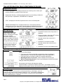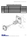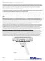
1
Industry Leader in RO Expertise and Membrane Applications since 1983™ Manual for Operation & Maintenance Of Twin Alternating Water Softener for Models: W-S744EMT W-S844EMT W-S940EMT W-S1054EMT W-S1252EMT W-S1354EMT W-S1465EMT W-S1665EMT Systems Membranes & Chemicals 2325 Cousteau Ct. Vista, CA 92081 • (760) 727-3711 • FAX: (760) 727-4427 Internet: www.appliedmembranes.com • E-mail: [email protected] Filters Document ID# OMS7-16EMT Revision: 09-07-2012 Installation and Service Manual – Twin Alternating Water Softener Valve Operation Quick Reference Guide Regeneration Screens During Regeneration: The display shows the time remaining in the current cycle. Pressing “REGEN” will advance to the next cycle. Regeneration Pending: In Alternator Systems when a unit is waiting to initiate the first cycle step of regeneration, “REGEN PndG” is displayed. “STbY” is displayed in Alternator Systems when a valve is in Standby state. “REGEN PndG RINSE FILL” is displayed whenever a zero-capacity tank has transferred to an off-line state and is currently waiting to initiate the second portion of a regeneration cycle. Viewed only when Delayed Rinse and Fill is set to ON. Set Time of Day In the event of a prolonged power outage, time of day flashes, indicating that it needs to be reset. All other information will be stored in memory no matter how long the power outage. Please complete the steps as shown to the right. (Time of day will only need to be set when a power outage lasts more than 8 hours, or when daylight savings time begins or ends.) Press NEXT until the time of day screen is displayed. Press and hold ▲ or ▼until the SET indicator is displayed and the hour flashes. Press ▲ or ▼until the correct hour is displayed. Press NEXT, the minutes will flash. Press ▲ or ▼until the correct minute is displayed. Press NEXT to return to the display screen. Button Operation and Function Scrolls to the Next Display Press once and release to schedule a regeneration at the preset delayed regeneration time. (Press and release again to cancel the regeneration.) Press and Hold for 3 seconds to initiate an immediate regeneration. While Regeneration is in Process: Press to advance to the next cycle. While in Programming Screens: Press to go backwards to the previous screen. Changes variable being displayed. Key sequence to lock and unlock program settings. Press and Hold for 3 seconds to initiate a control reset. The software version is displayed and the piston returns to the home/service position, resynchronizing the valve. Error Message If the word “ERROR” and a number are alternately flashing on the display, check the trouble shooting section of this manual to identify the error. Clear error by disconnecting the power supply at the PC board and reconnecting, or press the NEXT and REGEN buttons simultaneously for 3 seconds. Page 2 Copyright © 2012 Applied Membranes, Inc. All Rights Reserved. Installation and Service Manual –Twin Alternating Water Softener Table of Contents Design Basis & Specifications ................................................................................................................................................................ 4 Installation ................................................................................................................................................................................................ 5 Location .................................................................................................................................................................................................. 5 Loading the Resin .................................................................................................................................................................................. 5 Resin Quantity per Model ....................................................................................................................................................................... 6 Plumbing ................................................................................................................................................................................................ 6 Initial Start-Up ......................................................................................................................................................................................... 10 System Monitoring and Record Keeping ............................................................................................................................................. 11 Operating Conditions ............................................................................................................................................................................. 11 Operating Do’s and Don’ts .................................................................................................................................................................... 11 Maintenance............................................................................................................................................................................................ 12 Control Valve Operation & Service ....................................................................................................................................................... 13 Control Valve Specifications ................................................................................................................................................................. 13 General Warnings ................................................................................................................................................................................ 14 Control Valve General Features and Information ................................................................................................................................. 14 Regeneration Screens .......................................................................................................................................................................... 15 Set Time of Day .................................................................................................................................................................................... 15 Button Operation and Function............................................................................................................................................................. 15 Error Message ...................................................................................................................................................................................... 15 Programming Control Valve Options and Display Details .................................................................................................................. 16 User Displays ....................................................................................................................................................................................... 16 Twin Alternating Softener Recommended Programming Overview...................................................................................................... 17 Configuration Settings (Pre-Programmed to Factory Defaults) .......................................................................................................... 18 Regeneration Cycle Time Settings (Pre-Programmed to Factory Defaults) ...................................................................................... 19 Installer Display Settings (Program at Location)................................................................................................................................. 20 Diagnostics ........................................................................................................................................................................................... 21 Control Valve Drawings and Components ........................................................................................................................................... 22 Front Cover & Drive Assembly ............................................................................................................................................................. 22 CV1 Drive Cap Assembly, Downflow Piston, Regenerate Piston & Spacer Stack Assembly .............................................................. 23 Injector Cap, Injector Screen, Injector, Plug and O-Ring ...................................................................................................................... 24 Refill Flow Control Assembly and Refill Port Plug ................................................................................................................................ 25 Water Meter, Meter Plug and Mixing Valve .......................................................................................................................................... 26 Drain Line – ¾” ..................................................................................................................................................................................... 27 CV1 with 1.050” Distributor Tube Opening Identification ...................................................................................................................... 28 Installation Fitting Assembly ................................................................................................................................................................. 28 Flow Diagram, Service ......................................................................................................................................................................... 29 Flow Diagram, Backwash ..................................................................................................................................................................... 29 Flow Diagram, Brine ............................................................................................................................................................................. 30 Flow Diagram, Rinse ............................................................................................................................................................................ 30 Flow Diagram, Fill ................................................................................................................................................................................. 31 CV1 Service Spanner Wrench.............................................................................................................................................................. 32 Control Valve Components Description ............................................................................................................................................... 33 Drive Assembly .................................................................................................................................................................................... 33 Drive Cap Assembly, Main Piston, Regenerant Piston ......................................................................................................................... 33 Spacer Stack Assembly........................................................................................................................................................................ 33 Injector Cap, Screen, Injector Plug and Injector ................................................................................................................................... 34 Refill Flow Control Assembly ................................................................................................................................................................ 34 Drain Line Flow Control and Fitting Assembly ...................................................................................................................................... 34 Installation Fitting Assemblies .............................................................................................................................................................. 34 Water Meter or Meter Plug ................................................................................................................................................................... 35 Control Valve Service Instructions ....................................................................................................................................................... 35 Drive Assembly .................................................................................................................................................................................... 35 Drive Cap Assembly, Main Piston and Regenerant Piston ................................................................................................................... 36 Spacer Stack Assembly........................................................................................................................................................................ 37 Injector Cap, Screen, Injector Plug and Injector ................................................................................................................................... 37 Refill Flow Control Assembly or Refill Port Plug ................................................................................................................................... 38 Water Meter.......................................................................................................................................................................................... 38 Drain Line Flow Control ........................................................................................................................................................................ 38 Troubleshooting ..................................................................................................................................................................................... 39 Product Warranty ................................................................................................................................................................................... 44 Page 3 Copyright © 2012 Applied Membranes, Inc. All Rights Reserved. Installation and Service Manual – Twin Alternating Water Softener Design Basis & Specifications Table 1 - Specifications Flow Rate** (GPM) Model No.* W-S744EMT W-S844EMT W-S940EMT W-S1054EMT W-S1252EMT W-S1354EMT W-S1465EMT W-S1665EMT 5gpm per ft² 1 2 2 2 4 4 5 7 15gpm per ft² 4 5 6 7 12 14 16 21 Backwash Flow** Volume of Resin (Cu. Ft.) Softening Resin (Only) (GPM) 1.3 1.7 2.2 2.7 4.2 5.3 5.3 6.5 Per Tank Total 0.50 0.60 0.75 1.25 1.75 2.00 3.00 3.50 1.00 1.20 1.50 2.50 3.50 4.00 6.00 7.00 Total (Incl. Underbed) Per Tank Total 0.60 0.70 0.85 1.45 2.05 2.30 3.50 4.00 1.2 1.4 1.7 2.9 4.1 4.6 7.0 8.0 Resin Tank (2) (Dia”×H”) 7×44 8×44 9×40 10×54 12×52 13×54 14×65 16×65 Brine Tank (Dia”×H”) 18×33 18×33 18×40 18×40 18×40 18×40 24×41 24×41 Valve & In/Out Conn. 1” 1” 1” 1” 1” 1” 1” 1” * Softeners are available with USA or European style plugs and voltages. The appropriate voltage code is added to the end of the model. 120V AC/60Hz with USA cord = US Example: W-S744EMT-US European 220V AC = EU (EU plug is removable to convert into universal 220v cord) Example: W-S744EMT-EU ** 5 gpm per sq. ft. of media is the best design condition for filtration. For relatively clean water, you may go up to design criteria of 15 gpm per sq. ft. Backwash flow rate based on 25 psi pressure drop. DISCLAIMER: The information contained in this document is subject to change without notice. Applied Membranes, Inc. shall not be liable for technical or editorial omissions made herein; nor for incidental or consequential damages resulting from the furnishing, performance, or use of this material. READ THIS MANUAL: Prior to operating or servicing this unit, this manual must be read and understood. If anything is not clear, call for assistance before proceeding. Keep this and other associated manuals for future reference and for new operators or qualified service personnel. USE PROPER POWER CONNECTIONS: Use proper wiring and connection methods to satisfy local electrical codes. SHOCK HAZARD: Connect this unit to a properly grounded connection in accordance with the National Electrical Code. DO NOT, under any circumstances, remove the ground wire or ground prong from any power plug. Do not use extension cords or an adapter without proper consideration. SERVICE WARNING: To prevent electrical shock, disconnect power to the system prior to servicing. WARNING: Do not make any alteration or modification in the wiring or plumbing of the system. This can result in damage to the system and cause injury to operators or users. WARNING: Flush the system for at least 30 minutes before use to remove all chemicals present. CAUTION: Never let the softener freeze. Freezing can damage the resin tank. Page 4 Copyright © 2012 Applied Membranes, Inc. All Rights Reserved. Installation and Service Manual –Twin Alternating Water Softener Installation Unpack Softener. Inspect assemblies for damage (cracked couplings, broken or split pipes, loose straps, etc.). Location Select a location for the Softener with adequate clearance from walls and other equipment to allow access on all sides of the tanks. The unit must be located near a drain able to accommodate the backwash flow rate of your unit (refer to the design basis and specifications table). This is in addition to any other equipment sharing the drain. Select a location for the brine tank. Ensure floor beneath the brine tank is clean and level. Install tubing from the brine tank and injector onto the control valve. A grounded power supply of the appropriate voltage and a local disconnect switch is required. Softeners are available with USA or European style plugs and voltages. The appropriate voltage code is added to the end of the model. 120V AC/60Hz with USA cord = US Example: W-S744EMT-US European 220V AC = EU (EU plug is removable to convert into universal 220v cord) Example: W-S744EMT-EU Caution: The unit must not be located near any corrosive chemicals, or in an area where the temperature may exceed 113°F (45°C). Warning: The power supply must be properly grounded to avoid injury from electrical shock. If softener shipped unloaded (packaged separately outside of the tank) then continue with the loading instructions. If the softener was shipped loaded, please skip to plumbing. Loading the Resin 1. Place each resin tank on a level, solid surface in the correct position for installation. Lift the riser tube from the tank, keeping the attached hub within the opening of the tank. Within the tank, assemble the laterals onto the hub, twisting each lateral into the hub to lock securely. Gently lower the assembly to the bottom of the tank. The top of the riser tube should be about level with the top of the tank. 2. The “riser tube” inside the media/resin tank delivers treated water to your control valve. It will need to be temporarily covered with tape on the top end to prevent anything from falling down inside the tube during loading. 3. Step back and look at the tank to make sure it is standing straight, and not tilted. The black base on the bottom of the tank should also be straightened before filling the tank. If your tank is tilted, simply pick up the tank 2-3 inches off the floor and drop it gently (but firmly) down, favoring the side of the base that needs to be adjusted. 4. Before loading the resin, fill the tank with 2-3 feet of water (or 1/3 full, depending on the tank size), to soften the fall of the rocks and prevent damage to the distributor. To load the resin, use a funnel with a 2” opening in the top of the softener tank with the riser tube still inside. Make sure the riser tube is covered with tape to keep resin out. 5. Scoop the resin into the funnel, slowly letting it fall down inside the softener tank around the riser tube. Fill the tank with the resin provided, pouring in the following order (1st will end up on the bottom of the tank, last will end up at the top of the tank, etc.). Note: The tank will be approximately ½ - ⅔ full after loading is complete. Refer to table on the next page for the proper quantities of each component. I. Gravel – YMGRVL11618 – 0.5 CF (50 lbs) per bag II. Resin – CGS – 1 CF (50 lbs) per bag 6. Remove the funnel from the top of the tank, and the tape from the end of the riser tube. Brush any loose resin off the top opening of the tank. 7. The bottom of the control valve has an opening with O-rings inside. Position the valve over the top of the softener tank, making sure the top of the riser tube inserts inside the opening in the bottom of the valve. Page 5 Copyright © 2012 Applied Membranes, Inc. All Rights Reserved. Installation and Service Manual – Twin Alternating Water Softener 8. Screw the valve down into the softener tank. Another person should hold the tank as the valve is being snugly tightened onto the tank. Do not over-tighten. Tighten until snug, tighten a bit more, then STOP. The large o-ring will seal itself. 9. Repeat all steps for the second resin tank. Resin Quantity per Model Table 2 – Resin Quantities Model No. (-US or -EU) W-S744EMT W-S844EMT W-S940EMT W-S1054EMT W-S1252EMT W-S1354EMT W-S1465EMT W-S1665EMT Gravel /16 x ⅛ I Total Qty. in Qty. Per Tank Twin Softener 0.1 CF (10 lbs) 0.2 CF (20 lbs) 0.1 CF (10 lbs) 0.2 CF (20 lbs) 0.1 CF (10 lbs) 0.2 CF (20 lbs) 0.2 CF (20 lbs) 0.4 CF (40 lbs) 0.3 CF (30 lbs) 0.6 CF (60 lbs) 0.3 CF (30 lbs) 0.6 CF (60 lbs) 0.5 CF (50 lbs) 1.0 CF (100 lbs) 0.5 CF (50 lbs) 1.0 CF (100 lbs) Resin 1 II Qty. Per Tank 0.5 CF (25 lbs) 0.6 CF (30 lbs) 0.75 CF (38 lbs) 1.25 CF (63 lbs) 1.75 CF (88 lbs) 2.0 CF (100 lbs) 3.0 CF (150 lbs) 3.5 CF (175 lbs) Total Qty. in Twin Softener 1.0 CF (50 lbs) 1.2 CF (60 lbs) 1.5 CF (76 lbs) 2.5 CF (126 lbs) 3.5 CF (176 lbs) 4.0 CF (200 lbs) 6.0 CF (300 lbs) 7.0 CF (350 lbs) Plumbing Note: All plumbing is to be done in accordance with state and local codes. Caution: Before placing wall anchors to support piping ensure that no electrical conduit or wiring is located behind the intended mounting location. Note: The control valve, fittings and/or bypass are designed to accommodate minor plumbing misalignments but are not designed to support the weight of a system or the plumbing. 1. Plumb the Motorized Alternating Valve (MAV) accordign to the photos/drawings. Note: Ensure that the valve labeled “Alt A” is connected to the “A” port on the MAV, and the valve labeled “Alt B” is connected to the “B” port. Page 6 Copyright © 2012 Applied Membranes, Inc. All Rights Reserved. Installation and Service Manual –Twin Alternating Water Softener 2. Install connecting piping between raw water source and input pipe on control valve. The installation fittings connect to the control valve or the bypass valve using nuts that only require hand tightening. Do not use a pipe wrench to tighten nuts on installation fittings. The split ring design, incorporated into the installation fittings allows approximately 2 degrees off axis alignment to the plumbing system. The installation fittings are designed to accommodate minor plumbing misalignments but are not designed to support the weight of a system or the plumbing. When assembling the installation fitting package, connect the fitting to the plumbing system first and then attach the nut, split ring and o-ring. Heat from soldering or solvent cements may damage the nut, split ring or o-ring. Solder joints should be cool and solvent cements should be set before installing the nut, split ring and o-ring. Avoid getting primer and solvent cement on any part of the orings, split rings, bypass valve or control valve. Solvent cements and primers should be used in accordance with the manufacturer’s instructions. Slip the nut onto the fitting first, then the split ring second and the o-ring last. Hand tighten the nut. If the fitting is leaking tightening the nut will not stop the leak. Remove the nut, remove the fitting, and check for damage or misalignment of the o-ring. Do not use pipe dope or other sealant on threads. Use teflon tape on threaded inlet, outlet and drain fittings. Teflon tape is not necessary on the nut connection or caps because of o-ring seals. 3. Install drain line from control valve to a free flowing drain. If the drain line is a ⅝” flexible polytube, slide the nut onto the polytube, then place the polytube insert into the end of the polytube and tighten the nut on to the ¾” drain line fitting. The nut is only designed for use with fexible polytube. Use other nuts if attaching different materials. (To access the drain line flow control, remove the locking Page 7 Copyright © 2012 Applied Membranes, Inc. All Rights Reserved. Installation and Service Manual – Twin Alternating Water Softener clip by pulling it straight out. Pull fitting out and replace the locking clip so that it is not misplaced. The drain line fitting is pressed in and has an o-ring seal.) 4. Install Brine/Refill line between brine tank and softener refill port. To complete the regenerant line connection, orientate the outlet in the desired direction and push the plastic insert into the polytube. Push the polytube into the nut. Do not use pipe dope or other sealants on threads. The threads for the compression nut do not need Teflon tape. Tighten the nut securely to create a pressure tight connection. A pliers or crescent wrench may be used to tighten or unscrew the nut. The nut, gripper and retainer sleeve is a 3 piece assembly that can come apart if removed from the elbow body. Parts must be reassembled exactly as shown in refill flow control assembly drawing to function properly. If the nut is completely removed from the body, slip the nut, plastic gripper and retainer sleeve on to the tube then tighten on to the fitting. 5. Install piping between Softener output and point of use. The installation fittings connect to the control valve or the bypass valve using nuts that only require hand tightening. Do not use a pipe wrench to tighten nuts on installation fittings. The split ring design, incorporated into the installation fittings allows approximately 2 degrees off axis alignment to the plumbing system. The installation fittings are designed to accommodate minor plumbing misalignments but are not designed to support the weight of a system or the plumbing. When assembling the installation fitting package, connect the fitting to the plumbing system first and then attach the nut, split ring and o-ring. Heat from soldering or solvent cements may damage the nut, split ring or o-ring. Solder joints should be cool and solvent cements should be set before installing the nut, split ring and o-ring. Avoid getting primer and solvent cement on any part of the orings, split rings, bypass valve or control valve. Solvent cements and primers should be used in accordance with the manufacturer’s instructions. Slip the nut onto the fitting first, then the split ring second and the o-ring last. Hand tighten the nut. If the fitting is leaking tightening the nut will not stop the leak. Remove the nut, remove the fitting, and check for damage or misalignment of the o-ring. Do not use pipe dope or other sealant on threads. Use teflon tape on threaded inlet, outlet and drain fittings. Teflon tape is not necessary on the nut connection or caps because of o-ring seals. 6. Connect MAV Cables to valve head Alt A: - On the backside of the valve, remove the strain reief cover with a screwdriver. - Remove the cover of the valve by pulling out on the release tabs located on each side of the cover. - Feed the MAV motor cable and interconnect cable through the hole in the back of the valve. - Connect the MAV motor cable to the two pin connector labeled “DRIVE” on the PC Board. - Connect the interconnect cable to the three pin connector labelled “INTERCONNECT CABLE” on the PC Board. - After connecting the cables, weave the wires through the strain releif on the backside of the valve, and replace the strain relief cover and screw. Replace the valve cover. Page 8 Copyright © 2012 Applied Membranes, Inc. All Rights Reserved. Installation and Service Manual –Twin Alternating Water Softener 7. Connect MAV Cables to valve head Alt B: (Refer to the above photos) - On the backside of the valve, remove the strain reief cover with a screwdriver. - Remove the cover of the valve by pulling out on the release tabs located on each side of the cover. - Feed the other end of the interconnect cable through the hole in the back of the valve. - Connect the interconnect cable to the three pin connector labelled “INTERCONNECT CABLE” on the PC Board. - After connecting the cables, weave the wires through the strain releif on the backside of the valve, and replace the strain relief cover and screw. Replace the valve cover. Page 9 Copyright © 2012 Applied Membranes, Inc. All Rights Reserved. Installation and Service Manual – Twin Alternating Water Softener Initial Start-Up For detailed programming and operating information, please refer to the control valve section of this manual. 1. Check all piping connections and make sure feed valves are open. Inspect plumbing for leaks. 2. Check that control valve is connected to electrical source. 3. Open Raw Water source valve. Note: Check for leaks throughout system as pressure is applied. Note: For detailed information on the control valve operation, see the valve manual enclosed. 4. Initiate manual regeneration of the control valve to regenerate: press “REGEN” button for three seconds. 5. Ensure drain line flow remains steady for 10 minutes or until clear. Step through the different regeneration cycles by pressing REGEN. 6. Observe regeneration effluent and continue to regenerate until discharge is clear. Steps 4 and 5 may need to be repeated as necessary. 7. Observe that brine tank is filling during brine tank refill cycle. 8. Install brine tank overflow line. Attach plastic tubing to the fittings from the brine tank and run to an open drain. This drain line will not be under pressure. DO NOT tie into the backwash drain line. This line should be higher than the normal drain line, and must be a separate line from fitting to drain. It is a safety overflow drain and will not be in use during normal operation. 9. Observe that valve advances through the different regeneration cycles and ends in service. Step through the different regeneration cycles by pressing REGEN. 10. Fill brine tank with salt. Salt may be sodium chloride (NaCl) or potassium chloride (KCl). Fill tank to only 2/3 full. NOTE: The brine tank holds a large quantity of salt, so you will not need to refill at frequent intervals. Refilling the brine tank with salt should be performed after your system is successfully installed and has been operating trouble-free. Brine tank should be refilled with salt at least 2 hours before the next generation is performed. 11. Review control valve operations section of this manual and ensure settings are properly programmed before placing the softener in service. Page 10 Copyright © 2012 Applied Membranes, Inc. All Rights Reserved. Installation and Service Manual –Twin Alternating Water Softener System Monitoring and Record Keeping Monitor Softener daily and record all pertinent data. This data is needed to determine operating efficiency and for performing system maintenance. The latter includes changing of the resin, pressure drop across the softener tank and control valve. Note: Warranty Claims cannot be processed without adequate operating data and Softener history. Operating Conditions For optimum Softener performance, observe the following: Maintain a minimum of 25 psi during backwash cycle. Water pressure should not exceed 120 psi across softener tank. Water temperature should not exceed 110 °F. Maintain salt level above water level in brine tank. CAUTION: Hydrocarbons such as kerosene, benzene, gasoline, etc., may damage products that contain o-rings or plastic components. Exposure to such hydrocarbons may cause the products to leak. Do not use the product(s) contained in this document on water supplies that contain hydrocarbons such as kerosene, benzene, gasoline, etc. Operating Do’s and Don’ts DO: Monitor system and keep a daily log. Maintain salt above water level. Maintain proper water pressure for backwashing. DON’T: Permit oils or fats in feed water. Shut down system for extended periods. Exceed operating pressures or temperatures. Backwash filter with insufficient water flow. Page 11 Copyright © 2012 Applied Membranes, Inc. All Rights Reserved. Installation and Service Manual – Twin Alternating Water Softener Maintenance Removal & Replacement of Media/Resin Tools Needed: Wrench (to removing piping) Screwdriver wide blade Tarp Buckets (for materials) Wet and Dry Vacuum Cleaner or Tarp Food Grade Glycerin 1. Turn off water to softener. 2. Relieve pressure in tank by either opening a downstream valve or cycling the control valve into the back wash position. 3. If a by-pass valve is installed, place it in the by-pass position. 4. Disconnect drain line. 5. Turn off electrical source and disconnect control valve. Remove any wiring connected to control valve. 6. Loosen plumbing from control valve. 7. Carefully move Softener forward until it clears plumbing. 8. Move Softener to an area where access is available to all sides; be sure to be careful of all nearby plumbing. 9. Carefully loosen control valve on softener tank top. Slowly unscrew valve being careful not to damage threads in top of tank. 10. When valve is loose from top of tank, slowly twist it back and forth to remove it from top of distributor tube inside tank. 11. To remove softener resin from tank choose one of the recommended methods below: a. Vacuum Removal: Vacuum all material out of tank and then wash inside with clean water. b. Manual Removal: Place a canvas on floor to catch filter and other materials dumped from tank. Lay tank on its side and tip it up to dump softener and other materials out of tank. Slowly rotate tank as it is being dumped. When all material is out of tank wash it with clean water. Note: Dispose of resin by local procedures or laws. 12. Place tarp or other floor covering where mineral tank is to be loaded, place tank in the middle of tarp. 13. Inspect distributor tube for cracks or damage. Inspect basket on end of tube for crushed or broken pieces. 14. Inspect top collector for cracks or damage. 15. Clean threads in top of mineral tank. Use glycerin to lubricate threads. 16. Reinstall distributor tube in mineral tank. 17. Replace resin as per resin loading instructions. 18. Perform start-up procedure. Page 12 Copyright © 2012 Applied Membranes, Inc. All Rights Reserved. Installation and Service Manual –Twin Alternating Water Softener Control Valve Operation & Service CV1 Control Valves with Metered Regeneration Control Valve Specifications Minimum/Maximum Operating Pressures: Minimum/Maximum Operating Temperatures: 20 psi (138 kPa, 1.4 bar) to 125 psi (862 kPa, 8.6 bar) 40°F (4°C) to 110°F (43°C) No user serviceable parts are on the PC board, the motor, or the power adapter. The means of disconnection from the main power supply is by unplugging the power adapter from the wall. AC Adapter Supply Voltage Supply Frequency Output Voltage Output Current U.S. 120 V AC 60 Hz 12 V AC 500 Ma International 230 V AC 50 Hz 12 V AC 500 Ma Page 13 Copyright © 2012 Applied Membranes, Inc. All Rights Reserved. Installation and Service Manual – Twin Alternating Water Softener General Warnings The control valve, fittings and/or bypass are designed to accommodate minor plumbing misalignments but are not designed to support the weight of a system or the plumbing. Do not use Vaseline, oils, other hydrocarbon lubricants or spray silicone anywhere. A silicone lubricant may be used on black o-rings but is not necessary The nuts and caps are designed to be unscrewed or tightened by hand or with the special plastic wrench. If necessary pliers can be used to unscrew the nut or cap. Do not use a pipe wrench to tighten or loosen nuts or caps. Do not place a screwdriver in the slots on caps and/or tap with a hammer. The nuts and caps are designed to be unscrewed or tightened by hand or with the special plastic wrench. If necessary a pliers can be used to unscrew the nut or cap. Do not use a pipe wrench to tighten or loosen nuts or caps. Do not place a screwdriver in the slots on caps and/or tap with a hammer. After completing any valve maintenance involving the drive assembly or the drive cap assembly and pistons unplug power source jack from the printed circuit board (black wire) and plug back in or press and hold NEXT and REGEN buttons for 3 seconds. The cover button may have other names like “SET HOUR”, “CLOCK” or “SET CLOCK” but the circuit board is labeled with SET. This resets the electronics and establishes the service piston position. The display should flash all wording, then flash the software version and then reset the valve to the service position. Do not use pipe dope or other sealants on threads. Use Teflon tape on the threaded inlet, outlet and drain fittings. Teflon tape is not necessary on the nut connection or caps because of o-ring seals. All plumbing should be done in accordance with local plumbing codes. The pipe size for the drain line should be a minimum of ½”. Backwash flow rates in excess of 7 gpm (26.5 lpm) or length in excess of 20’ (6.1m) require ¾” drain line. Solder joints near the drain must be done prior to connecting the drain line flow control fitting. Leave at least 6” between the drain line control fittings and solder joints when soldering pipes that are connected on the drain line control fitting. Failure to do this could cause interior damage to the drain line flow control fitting. When assembling the installation fitting package (inlet and outlet), connect the fitting to the plumbing system first and then attach the nut, split ring and o-ring. Heat from soldering or solvent cements may damage the nut, split ring or o-ring. Solder joints should be cool and solvent cements should be set before installing the nut, split ring and o-ring. Avoid getting primer and solvent cement on any part of the o-rings, split rings, bypass valve or control valve. Plug into an electrical outlet. Note: All electrical connections must be connected according to local codes. (Be certain the outlet is uninterrupted.) Install grounding strap on metal pipes. Control Valve General Features and Information This fully automatic control valve is designed as the primary control center to direct and regulate all cycles of a downflow regeneration water softener. The control valves included with this system are equipped with a motorized alternating valve to facilitate a twin alternating tank softener system, for uninterrupted flow of treated water. In Twin Alternating Softeners, one resin tank is always in service, while the other tank is in standby. When the meter determines that the resin is near its capacity, it will switch the tank in standby to be in service, and the tank containing the exhausted resin switches into regeneration, and then into standby. The injector regulates the flow of brine or other regenerants. The control valve regulates the flow rates for backwashing, rinsing, and the replenishing of treated water into a regenerant tank. The control valve uses no traditional fasteners (e.g. screws); instead clips, threaded caps and nuts and snap type latches are used. Caps and nuts only need to be firmly hand tightened because radial seals are used. Tools required to service the valve include one small blade screw driver, one large blade screw driver, pliers and a pair of hands. A plastic wrench is available which eliminates the need for screwdrivers and pliers. Disassembly for servicing takes much less time than com parable products currently on the market. Control valve installation is made easy because the distributor tube can be cut ½” above to ½” below the top of tank thread. The distributor tube is held in place by an o-ring seal and the control valve also has a bayonet lock feature for upper distributor baskets. The AC adapter comes with a 15 foot power cord and is designed for use with the control valve. The AC adapter is for dry location use only. The control valve maintains timekeeping for up to 8 hours if the power goes out and the battery is not depleted. After 8 hours, the only item that needs to be reset is the time of day; valve status and programming are permanently stored in the nonvolatile memory. If a power loss lasts less than 8 hours and the time flashes on and off, the time of day should be reset and the non-rechargeable battery should be replaced. Page 14 Copyright © 2012 Applied Membranes, Inc. All Rights Reserved. Installation and Service Manual –Twin Alternating Water Softener Valve Operation Quick Reference Guide Regeneration Screens During Regeneration: The display shows the time remaining in the current cycle. Pressing “REGEN” will advance to the next cycle. Regeneration Pending: In Alternator Systems when a unit is waiting to initiate the first cycle step of regeneration, “REGEN PndG” is displayed. “STbY” is displayed in Alternator Systems when a valve is in Standby state. “REGEN PndG RINSE FILL” is displayed whenever a zero-capacity tank has transferred to an off-line state and is currently waiting to initiate the second portion of a regeneration cycle. Viewed only when Delayed Rinse and Fill is set to ON. Set Time of Day In the event of a prolonged power outage, time of day flashes, indicating that it needs to be reset. All other information will be stored in memory no matter how long the power outage. Please complete the steps as shown to the right. (Time of day will only need to be set when a power outage lasts more than 8 hours, or when daylight savings time begins or ends.) Press NEXT until the time of day screen is displayed. Press and hold ▲ or ▼until the SET indicator is displayed and the hour flashes. Press ▲ or ▼until the correct hour is displayed. Press NEXT, the minutes will flash. Press ▲ or ▼until the correct minute is displayed. Press NEXT to return to the display screen. Button Operation and Function Scrolls to the Next Display Press once and release to schedule a regeneration at the preset delayed regeneration time. (Press and release again to cancel the regeneration.) Press and Hold for 3 seconds to initiate an immediate regeneration. While Regeneration is in Process: Press to advance to the next cycle. While in Programming Screens: Press to go backwards to the previous screen. Changes variable being displayed. Key sequence to lock and unlock program settings. Press and Hold for 3 seconds to initiate a control reset. The software version is displayed and the piston returns to the home/service position, resynchronizing the valve. Error Message If the word “ERROR” and a number are alternately flashing on the display, check the trouble shooting section of this manual to identify the error. Clear error by disconnecting the power supply at the PC board and reconnecting, or press the NEXT and REGEN buttons simultaneously for 3 seconds. Page 15 Copyright © 2012 Applied Membranes, Inc. All Rights Reserved. Installation and Service Manual – Twin Alternating Water Softener Programming Control Valve Options and Display Details The control valve offers multiple procedures that allow the valve to be modified to suit the needs of the installation. These procedures are: • User Displays • Configuration Settings • Cycle Times Settings (for Regeneration) • Installer Display Settings • Diagnostics These procedures can be accessed in any order. Details on each of the procedures are provided below and on the following pages. At the discretion of the installer, the end user can access all settings. To “lock out” access to programming settings, press the following key sequence: When locked, the valve can be unlocked by pressing the same key sequence. User Displays When in normal operation, one of five displays may be shown. Pressing NEXT will alternate between the displays. User Screen 1 Typical user display. Shows volume remaining (in gallons) until next regeneration. User Screen 2 Displays number of days to next regeneration. User Screen 3 Displays flow rate in gallons per minute. User Screen 4 Displays total flow in gallons since last reset. (Press and hold ▼ for 3 seconds to reset to 0.) User Screen 5 Shows current time. Page 16 Copyright © 2012 Applied Membranes, Inc. All Rights Reserved. Installation and Service Manual –Twin Alternating Water Softener Twin Alternating Softener Recommended Programming Overview Prior to starting the programming step, connect the interconnect cable to each control valve board’s three-pin connector labeled “INTERECONNECT”. Also connect the meter cord to the three pin connector labeled “METER” on “Alt-A” valve only. Table 3 – Valve Programming Steps for Recommended Default Program “ALT A” Valve Setting “ALT B” Valve Setting Configuration Settings Step 2CS 1.0 1.0 Valve Size Step 3CS ◄ Volume (no # in display) ◄ Volume (no # in display) Regeneration Type Step 4CS on 0 on 0 Regeneration Timing Step 5CS ALTA ALTb Twin Alternating Configuration Step 6CS oFF oFF Rinse/Refill Delay Option Step 7CS oFF oFF Pressure Differential Option Valve Programming Section (See following pages) Installer Setup Softening Capacity Between Regeneration Days Override Option Regeneration Cycle Times Settings Softener or Filter Setup Backwash Length Regenerant Draw Length Second Backwash Length Rinse Length Regenerant Refill Length Step 3I Enter Volume Capacity (See Table 4) Set Day Override to “oFF” Enter Volume Capacity (Same as Valve A) Set Day Override to “oFF” Step 2CT Step 3CT Step 4CT Step 5CT Step 6CT Step 7CT SOFTENING 8 60 8 4 See Table 4 SOFTENING 8 60 8 4 Same as Valve A Step 2I Table 4 – Salt Usage and Grains Capacity Settings The softener can be set to use different amounts of salt per regeneration. The higher the quantity of salt used, the higher the resin’s hardness removing capacity will be. AMI recommends using 10 lbs/cu.ft. setting. Alternatively, higher salt usage may be set in order to maximize resin capacity between regenerations, or a lower salt usage settings can be used to reduce salt consumption, but this will result in more frequent regeneration. This data is also shown below. To find Volume Capacity (for Step 2I) : o Find your model and desired salt setting from the below table (10 lbs/cu.ft. recommended) to find the total GRAINS capacity for your model. o Divide the grains capacity by the number of grains per gallon of hardness present in the feed water. (Example: If feed water is 10 grains per gallon hardness, the W-S744EMT (with 10lbs /cu.ft. salt setting) has 14,500 grains capacity. 14,500 ÷ 10 = 1,450 gallon capacity) To find Brine Fill Time (for Step 7CT): Use number from “Brine Fill Time” column for your model in the appropriate salt settings column. Softener Model Number Capacity (per tank) at Various Lbs of Salt per Regeneration Settings 10 lbs/cu.ft. 7.5 lbs/cu.ft 5 lbs/cu.ft. (Recommended) Grains Salt Used Brine Grains Salt Used Brine Grains Salt Used Brine Grains Salt Used Brine Capacity per Fill Capacity per Regen Fill Capacity per Regen Fill Capacity per Regen Fill Regen Time Time Time Time 15 lbs/cu.ft. (minutes) W-S744EMT 15,000 W-S844EMT 18,000 W-S940EMT 22,500 W-S1054EMT 37,500 W-S1252EMT 52,500 W-S1354EMT 60,000 W-S1465EMT 90,000 W-S1665EMT 105,000 7.5 lbs 9.0 lbs 11.3 lbs 18.8 lbs 26.3 lbs 30.0 lbs 45.0 lbs 52.5 5.0 6.0 7.5 12.5 17.5 20.0 30.0 35.0 (minutes) 14,500 17,400 21,750 36,250 50,750 58,000 87,000 101,500 5.0 lbs 6.0 lbs 7.5 lbs 12.5 lbs 17.5 lbs 20.0 lbs 30.0 lbs 35.0 lbs 3.3 4.0 5.0 8.3 11.6 13.2 19.8 23.1 (minutes) 12,850 15,420 19,275 32,125 44,975 51,400 77,100 89,950 3.8 lbs 4.5 lbs 5.6 lbs 9.4 lbs 13.1 lbs 15.0 lbs 22.5 lbs 26.3 lbs 2.5 3.0 3.8 6.3 8.8 10.0 15.0 17.5 (minutes) 10,000 12,000 15,000 25,000 35,000 40,000 60,000 70,000 2.5 lbs 3.0 lbs 3.8 lbs 6.3 lbs 8.8 lbs 10.0 lbs 15.0 lbs 17.5 lbs 1.7 2.0 2.5 4.1 5.8 6.6 9.9 11.6 Page 17 Copyright © 2012 Applied Membranes, Inc. All Rights Reserved. Installation and Service Manual – Twin Alternating Water Softener Configuration Settings (Pre-Programmed to Factory Defaults) Step 1CS Press ▲ and ▼ simultaneously for 5 seconds and release. If screen in Step 2CS does not appear, the lock on the valve is activated. To unlock press ▼, NEXT, REGEN, ▲ in sequence, then press ▲and ▼ simultaneously for 5 seconds and release. Step 2CS Choose 1.0 (for 1” valve). Press NEXT to go to Step 3CS. Press REGEN to exit Configuration Settings. (Note: If 2.0L or 2.0 are selected an additional flow meter screen (not shown) will appear which does not apply to the configuration of this softener. If 2.0L or 2.0 is accidentally selected, press REGEN to return to step 2CS and select 1.0.) Step 3CS “Volume” arrow (with a blank number display) should be selected for twin softeners. If a different display (listed below) is shown, press the ▲or ▼ buttons to scroll through the options until the correct display is shown. When Volume (gallons) is selected the regeneration will occur after the specific volume has been used or on the day override (if selected) whichever comes first. Press NEXT to go to Step 4CS. Press REGEN to return to previous step. Step 4CS Press ▲ or ▼ to select to regenerate immediately on 0 (recommended for twin softeners) or at delayed time (not recommended). Note: If immediately on 0 option is not available, the wrong setting was selected in step 3CS. Press REGEN to return to step 3CS and correct the setting to “Volume”. Press NEXT to go to Step 5CS. Press REGEN to return to previous step. Step 5CS Press ▲ or ▼ to select “ALT” option. “Alt A” Valve should be marked “ALTA”; “Alt B” Valve should be marked “ALTB” Note: Check that the Alt A and Alt B Valves are connected to the proper connection points on the MAV as per the instructions in the Plumbing section of this manual. Press NEXT to go to Step 6CS. Press REGEN to return to previous step. Step 6CS Press ▲ or ▼ to set rinse and fill delay to “oFF”. (Note: Rinse and fill delays may be required in applications where a hardness meter is installed downstream. This would eliminate any potential spikes when the tanks switch from standby to operation which could trigger the hardness monitor to shut down the system. For normal operation, it is recommended this feature be set to “oFF”) Press NEXT to go to Step 7CS. Press REGEN to return to previous step. Step 7CS Press ▲ or ▼ to set external pressure differential option to “oFF”. Press NEXT to exit configuration settings. Press REGEN to return to previous step. Page 18 Copyright © 2012 Applied Membranes, Inc. All Rights Reserved. Installation and Service Manual –Twin Alternating Water Softener Regeneration Cycle Time Settings (Pre-Programmed to Factory Defaults) Step 1CT Press NEXT and ▼ simultaneously for 5 seconds and release. If screen in Step 2CT does not appear, the lock on the valve is activated. To unlock press ▼, NEXT, REGEN, ▲ in sequence, then press ▲and ▼ simultaneously for 5 seconds and release. Step 2CT Press ▲ or ▼ to select “SOFTENING” setting. (Note: if “FILTERING” setting is accidentally selected, only options 3CT & 6CT will appear.) Step 3CT Adjust the length of the backwash from 1 to 95 minutes using the ▲and ▼ buttons. Recommended: 8 Press NEXT to go to Step 4CT. Press REGEN to return to previous step. Step 4CT Adjust the length of the regenerant draw from 1 to 180 minutes using the ▲and ▼ buttons. Recommended: 60 Press NEXT to go to Step 5CT. Press REGEN to return to previous step. Step 5CT Adjust the length of the second backwash from 1 to 95 minutes using the ▲and ▼ buttons. Recommended: 8 Press NEXT to go to Step 6CT. Press REGEN to return to previous step. Step 6CT Adjust the length of the rinse from 1 to 95 minutes using the ▲and ▼ buttons. Recommended: 4 Press NEXT to go to Step 4CT. Press REGEN to return to previous step. Step 7CT Adjust the length of the regenerant refill from 0.1 – 99.0 minutes using the ▲and ▼ buttons. (See table 4) Press NEXT to go to exit Regeneration Cycle Times. Press REGEN to return to previous step. Page 19 Copyright © 2012 Applied Membranes, Inc. All Rights Reserved. Installation and Service Manual – Twin Alternating Water Softener Installer Display Settings (Program at Location) Step 1I To enter Installer Display press NEXT and ▲ simultaneously for 5 seconds and release. Step 2I Press ▲ or ▼ to enter the volumetric capacity in gallons. (See table 4.) Press NEXT to go to Step 3I. Press REGEN to return to previous step. Step 3I Press ▲ or ▼ to adjust the days override setting from 1 – 28 or OFF. Press NEXT to go to Step 4I. Press REGEN to return to previous step. Step 4I Regeneration time: Display should read “on 0”. If a time is displayed, return to configuration step 4CS to change to “on 0” Press NEXT to go to step 5I. Press REGEN to return to previous step. Step 5I Press ▲ or ▼ to adjust the regeneration minutes. Press NEXT to exit Installer Display Settings. Press REGEN to return to previous step. Page 20 Copyright © 2012 Applied Membranes, Inc. All Rights Reserved. Installation and Service Manual –Twin Alternating Water Softener Diagnostics Step 1D Press ▲ and ▼ simultaneously for 5 seconds and release. Then press ▲ and ▼ simultaneously for 3 seconds and release. If screen in Step 2D does not appear, the lock on the valve is activated. To unlock press ▼, NEXT, REGEN, ▲ in sequence, then press ▲and ▼ simultaneously for 5 seconds and release. Step 2D Display shows the number of days since a regeneration last occurred. Press NEXT to go to next step. Press REGEN to exit Diagnostics. Step 3D Display shows the volume of water treated in gallons since the last regeneration. Press NEXT to go to next step. Press REGEN to return to previous step. Step 4D Display shows the days in service since start up. Press NEXT to go to next step. Press REGEN to return to previous step. Step 5D Display shows the total number of regeneration cycles since start up. Press NEXT to exit Diagnostics. Press REGEN to return to previous step. Page 21 Copyright © 2012 Applied Membranes, Inc. All Rights Reserved. Installation and Service Manual – Twin Alternating Water Softener Control Valve Drawings and Components Front Cover & Drive Assembly Dwg. No. 1 2 3 4 5 6 Not Shown Not Shown Item No. V3715EE-01 V3107-01 V3106-01 V3408EE-03BOARD V3110 V3109 V3186 V3186-01 V3178 Description CV1EE Front Cover Assembly CV1 Motor Assembly CV1 Drive Bracket & Spring Clip CV1 EE PC Board CV1 Drive Reducing Gear 12×36 CV1 Drive Gear Cover CV1 AC Adapter 120v – 12v, USA CV1 AC Adapter Cord Only CV1 Drive Back Plate Page 22 Copyright © 2012 Applied Membranes, Inc. All Rights Reserved. Qty. Per Valve 1 1 1 1 3 1 1 1 Installation and Service Manual –Twin Alternating Water Softener CV1 Drive Cap Assembly, Downflow Piston, Regenerate Piston & Spacer Stack Assembly Dwg. No. 1 2 3 4 5 6 7 8 Not Shown Item No. V3005 V3004 V3178 V3011 V3174 V3135 V3180 V3105 V3001 V3001-02 Description CV1 Spacer Stack Assembly Drive Cap Assembly CV1 Drive Back Plate CV1Piston Downflow Assembly CV1Regenerant Piston O-Ring 228 O-Ring 337 O-Ring 215 (Distributor Type) CV1 Body Assembly, Downflow CV1 Mixing Valve Body Assembly Qty. Per Valve 1 1 1 1 1 1 1 1 1 Page 23 Copyright © 2012 Applied Membranes, Inc. All Rights Reserved. Installation and Service Manual – Twin Alternating Water Softener Injector Cap, Injector Screen, Injector, Plug and O-Ring Dwg. No. 1 2 3 4 Item No. Description Injector Color Typical Tank Dia.† (for downflow) Qty. Per Valve V3176 Injector Cap 1 V3152 O-Ring 315 1 n/a n/a V3177-01 Injector Screen Cage 1 V3010-1Z CV1 Injector Assembly Z Plug n/a n/a 1 V3010-1A CV1 Injector Assembly A Black 6” V3010-1B CV1 Injector Assembly B Brown 7” V3010-1C CV1 Injector Assembly C Violet 8” V3010-1D CV1 Injector Assembly D Red 9” V3010-1E CV1 Injector Assembly E White 10” 5 V3010-1F CV1 Injector Assembly F Blue 12” 1 V3010-1G CV1 Injector Assembly G Yellow 13” V3010-1H CV1 Injector Assembly H Green 14” V3010-1I CV1 Injector Assembly I Orange 16” V3010-1J CV1 Injector Assembly J Light Blue 18” V3010-1K CV1 Injector Assembly K Light Green 22” Not V3170 O-Ring 011 * n/a n/a Shown V3171 O-Ring 013 * * The injector plug and the injector each contain one 011 (lower) and 013 (upper) o-ring. For a filter that only backwashes, injector plugs are located in both holes. † Actual tank size used may vary depending on the design and application of the system. Tank diameter is an approximation for downflow softener using standard mesh synthetic cation exchange media regenerating with sodium chloride. Page 24 Copyright © 2012 Applied Membranes, Inc. All Rights Reserved. Installation and Service Manual –Twin Alternating Water Softener Refill Flow Control Assembly and Refill Port Plug Dwg. No. 1 2 3 4 5 6 7 8 9 Not Shown Item No. V3195-01 H4615 JCP-P-6 JCPG-6PBLK H4613 V3163 V3165-01* V3182 V3330-01 V3552 H4650 Description CV1 Refill Port Plug Assembly Elbow Locking Clip Polytube Insert ⅜” Nut ⅜” Elbow Cap ⅜” O-Ring 019 CV1 RFC Retainer Asy (0.5 gpm) CV1 RFC CV1 Brine Elbow Asy with RFC ⅜” CV1 Brine Elbow Asy with RFC ½” Elbow ½” with Nut and insert Qty. Per Valve 1 1 1 1 1 1 1 1 1 Option Page 25 Copyright © 2012 Applied Membranes, Inc. All Rights Reserved. Industry Leader in RO Expertise and Membrane Applications since 1983™ Water Meter, Meter Plug and Mixing Valve Dwg. No. 1 2 3 4 5 6 Item No. V3151 V3003* V3118-01 V3105 V3003-01 V3013 Description CV1 Nut, 1”, QC CV1 Meter Assembly CV1 Turbine Assembly O-Ring, 215 CV1 Meter Plug Assembly Mixing Valve Qty. Per Valve 1 1 1 1 1 Optional *Order number V3003 includes V3118-01 CV Turbine Assembly and V3105 O-Ring This Water Meter should not be used as the primary monitoring device for critical or health effect applications. Systems Membranes & Chemicals 2325 Cousteau Ct. Vista, CA 92081 • (760) 727-3711 • FAX: (760) 727-4427 Internet: www.appliedmembranes.com • E-mail: [email protected] Filters Document ID# OMS7-16EMT Revision: 09-07-2012 Installation and Service Manual –Twin Alternating Water Softener Drain Line – ¾” Dwg. No. 1 2 3 4* 5 6* 7 Item No. H4615 PKP10TS8-BULK V3192 V3158-01 V3163 V3159-01 V3162-013 V3162-017 V3162-022 V3162-027 V3162-042 V3162-053 Description Elbow Locking Clip Polytube insert ⅝” CV1 Nut ¾” Drain Elbow CV Drain Elbow ¾” Male O-Ring 019 CV1 DLFC Retainer Asy CV1 DLFC 1.3 gpm for ¾” CV1 DLFC 1.7 gpm for ¾” CV1 DLFC 2.2 gpm for ¾” CV1 DLFC 2.7 gpm for ¾” CV1 DLFC 4.2 gpm for ¾” CV1 DLFC 5.3 gpm for ¾” V3162-065 CV1 DLFC 6.5 gpm for ¾” Softener Used on ALL ALL ALL ALL ALL ALL W-S744EMT W-S844EMT W-S940EMT W-S1054EMT W-S1252EMT W-S1354EMT, W-S1465EMT W-S1665EMT Qty. Per Valve 1 Option Option 1 1 1 (1) of the model indicated in the column to the left *4 and 6 can be ordered as a complete assembly – V3331 CV1 Drain Elbow Retainer Assembly Replacement valves are shipped without drain line flow control, ¾” nut and ⅝” polytube insert – order DLFC separately and install before using. Page 27 Copyright © 2012 Applied Membranes, Inc. All Rights Reserved. Installation and Service Manual – Twin Alternating Water Softener CV1 with 1.050” Distributor Tube Opening Identification Installation Fitting Assembly Assembly Model Number: V3007 – CV1 Fitting, 1” PVC Male NPT Elbow Assembly Dwg. No. Item No. Description 1 V3151 CV1 Nut 1” Quick Connect 2 V3150 CV1 Split Ring 3 V3105 O-Ring 215 4 V3149 CV1 Fitting 1” PVC Male NPT Elbow Page 28 Copyright © 2012 Applied Membranes, Inc. All Rights Reserved. Qty. Per Assembly 2 2 2 2 Installation and Service Manual –Twin Alternating Water Softener Flow Diagram, Service Flow Diagram, Backwash Page 29 Copyright © 2012 Applied Membranes, Inc. All Rights Reserved. Installation and Service Manual – Twin Alternating Water Softener Flow Diagram, Brine Flow Diagram, Rinse Page 30 Copyright © 2012 Applied Membranes, Inc. All Rights Reserved. Installation and Service Manual –Twin Alternating Water Softener Flow Diagram, Fill Page 31 Copyright © 2012 Applied Membranes, Inc. All Rights Reserved. Installation and Service Manual – Twin Alternating Water Softener CV1 Service Spanner Wrench Model No: V3193-02 Although no tools are necessary to assemble or disassemble the valve, the CV1 wrench (shown below in various positions on the valve) may be purchased separately to aid in assembly or disassembly of the control valve. Page 32 Copyright © 2012 Applied Membranes, Inc. All Rights Reserved. Installation and Service Manual –Twin Alternating Water Softener Control Valve Components Description The CV1 control valves consist of the following components: 1. Drive Assembly 2. Drive Cap Assembly, Main Piston and Regenerant Piston 3. Spacer Stack Assembly 4. Injector Cap, Screen, Injector Plug and Injector 5. Drain Line Flow Control 6. Installation Fitting Assemblies 7. Water Meter or Meter Plug Drive Assembly The drive assembly consists of the following parts: Drive Bracket Printed Circuit (PC) Board Motor Drive Gears Drive Gear Cover The drive bracket holds the PC board, the motor, the drive gears and the drive gear cover in place. The PC board receives and retains information, displays the information, determines when to regenerate and initiates regeneration. The display shows different types of information in the initial system set up (for softeners or filters), installer display settings, diagnostics, valve history, or user display settings. The PC board powers the motor. The PC board’s two-prong jack connects wires to the direct current (DC) motor. The motor is held in place on the drive bracket by a spring-loaded clip and a small bulge in the plastic, which fits in one of the slots on the motor housing. The motor turns drive gears that drive the piston to cycle positions for backwashing, regeneration, rinsing, refill or service. The motor is fully reversible (turns both ways) and changes direction of rotation to change the direction of piston motion. The motor is easily replaced if necessary. There are three drive gears held in place by the drive gear cover. All three drive gears are the same size. A reflective coating is applied to the gears. As the center drive gear turns a light shines on the coating and a light sensing diode determines if a light pulse was returned. The PC board counts the pulses and determines when to stop driving the motor. Drive Cap Assembly, Main Piston, Regenerant Piston The drive gears turn the main gear of the drive cap assembly, which moves the piston. The screw-driven, horizontally moving piston stops at specific positions to direct the flow of water to backwash, regenerate, rinse or refill. The PC board determines the position of the piston by counting pulses produced when the piston is moved. An optical sensor looking at one of the reduction drive gears generates these pulses. Each cycle position is defined by a number of pulses. The counter is zeroed each time the valve goes to the service position. The PC board fi ds the service position by noting the increase in current delivered to the motor when the mechanical stop at the service position is reached. This method of controlling piston position allows for greater flexibility and requires no switches or cams (U.S. Patent 6444127). The valve included on your water softener includes a 1.25" diameter downflow piston. A regenerant piston is attached to the main piston. Spacer Stack Assembly The spacer stack assembly provides the necessary flow passage for water during the different cycles. The all-plastic spacer stack assembly (U.S. Patent 6402944) is a one-piece design which allows the stack to be removed using your fingers. The exterior of the stack is sealed against the body bore with self-lubricating EPDM o-rings, while the interior surface is sealed against the piston using slippery self-cleaning directional (one-way) silicone lip seals. The lip seals are clear in color and have a special slippery coating so that the piston does not need to be lubricated. Page 33 Copyright © 2012 Applied Membranes, Inc. All Rights Reserved. Installation and Service Manual – Twin Alternating Water Softener Injector Cap, Screen, Injector Plug and Injector The screen, injector and/or injector plug(s) are installed under the injector cap in an easy to access location on top of the valve. The injector cap contains four slots so no water accumulates in the cap. The injector cap is designed to be hand tightened. Under the injector cap there is an easy to clean removable screen to prevent fouling of the injector. There are two holes under the injector cap labeled “DN” and “UP”. The “DN” hole will be filled with an injector, which allows water to pass through the pathway. The “UP” hole will be filled with a plug (Order # V3010-1Z), which prevents water from travelling the pathway. The self-priming injector increases the velocity of the water, creating a zone of negative pressure that draws in the concentrated liquid regenerant, such as sodium chloride (brine), potassium permanganate, etc. The regenerant blends with the stream of water, which passes through the media to regenerate the bed. The injector provides a consistent regenerant/water mixture ratio over the entire operating pressure range of the control valve. The injector provides good performance in a variety of applications, which may involve elevated drain lines and long regenerant draw lengths. Refill Flow Control Assembly The refill flow control assembly consists of a refill flow elbow, refill flow control retainer assembly, refill flow control, polytube insert and nut assembly. The refill flow control retainer fits in the refill elbow. The refill flow control retainer houses the refill flow control which controls the flow rate when the regenerant tank is being refilled. The refill flow control is a flexible washer-like part with a small orifice and a precision molded contour that delivers a steady 0.5 gpm regenerant tank refill rate at varying inlet pressures. Refill is accomplished with treated water. The refill flow control assembly is installed in an easy to access refill elbow located on top of the control valve. The refill flow control assembly is attached to the control valve with a locking clip. The locking clip allows the elbow to rotate 270 degrees so the outlet can be orientated towards the regenerant tank. The control valve has a standard refill elbow to which a ⅜” flexible tube can be connected. An optional elbow can be ordered which accommodates a ½” flexible tube for a high regenerant draw rate situation (G injectors and larger). Both elbows use the same refill flow control and retainer. Drain Line Flow Control and Fitting Assembly The drain line flow control assembly includes a drain line flow control and a fitting. The drain line flow control allows proper media bed expansion by regulating the flow rate to the drain. The drain line flow control is a flexible washer-like part with an orifice and a precision molded contour. The flow rates are within ± 10% over the pressure range of 20 psi to 125 psi (1.4 bar to 8.6 bar). See table for flow rate information. Model No.* W-S744EMT W-S844EMT W-S940EMT W-S1054EMT W-S1252EMT W-S1354EMT W-S1465EMT W-S1665EMT Gallons per minute Backwash Flow Rate Liters per minute Drain Line Fitting Drain Line Flow Control Order No. Number on Drain Line Flow Control 1.3 1.7 2.2 2.7 4.2 5.3 5.3 6.5 4.9 6.4 8.3 10.2 15.6 20.1 20.1 24.6 ¾” ¾” ¾” ¾” ¾” ¾” ¾” ¾” V3162-013 V3162-017 V3162-022 V3162-027 V3162-042 V3162-053 V3162-053 V3162-065 013 017 022 027 042 053 053 065 The drain line flow control and fitting are located on top of the control valve and replaceable without the use of special tools. The drain line flow control can be installed in the standard ¾” drain line elbow, which accommodates ⅝” polytube or ¾” NPT drain line connections. The optional nut and polytube insert for the ¾” drain line elbow is designed for use with flexible polytube only. The ¾” drain line elbow can be rotated 180 degrees so the outlet can be orientated to the nearest drain. The same retainer is used for all drain line flow controls for the ¾” fitting. Drain line flow controls designed for the ¾” fitting are available for flow rates ranging from 0.7 to 10 gpm (2.6 to 37.9 lpm). Installation Fitting Assemblies Both elbow fittings have a unique drill out feature to allow a ¼” NPT connection to the inlet and/or outlet which can be used for a RO feed, test ports, pressure tap ports, etc. The installation fitting assemblies are sold in pairs and consist of two fittings, two nuts, two split rings and two o-rings. The installation fitting assemblies and the bypass valve are sold separately from the control valve. Page 34 Copyright © 2012 Applied Membranes, Inc. All Rights Reserved. Installation and Service Manual –Twin Alternating Water Softener Water Meter or Meter Plug The water meter is installed on the outlet side of the control valve. The water meter uses a turbine to measure gallons of treated water. The turbine rotates with the flow of water and reports its rate of rotation through Hall effect² circuitry to the printed circuit (PC) board. This rotation permits the PC board to record the total volume of treated water and the flow rate. The small centrally located magnet is shielded from water, which substantially reduces iron-fouling problems with the turbine. This Water Meter should not be used as the primary monitoring device for critical or health effect applications. Operating Pressures: 20 psi minimum, 12 psi maximum; Operating Temperatures: 40°F Minimum, 110°F Maximum The turbine is accurate to within ± 5% over a wide operating flow rate range (0.25 gpm [0.95 lpm] up to control valve maximums) and has a very low pressure drop. Water used for regeneration is not metered. If the control valve is set to prefill the regenerant, water used between the prefill cycle up to the start of the regeneration cycle is metered. If the control valve is in regeneration mode and there is a water demand, that water usage is not metered. When facing the front of the control valve, the water meter is positioned on the left-hand side of the control valve. Allow sufficient clearance to clean and repair the water meter without disconnecting the plumbing or disassembling any other parts of the control valve. Control Valve Service Instructions Drive Assembly Remove the valve cover to access the drive assembly. Disconnect the power source plug (black wire) from the PC board prior to disconnecting the motor or water meter plugs from the PC board. The power source plug connects to the four-pin jack. The motor plug connects to the two-pin jack on the left-hand side of the PC board. The water meter plug (gray wire) connects to the three-pin jack on the far right-hand side of the PC board. The PC board can be removed separately from the drive bracket but it is not recommended. Do not attempt to remove the display panel from the PC board. Handle the board by the edges. To remove the PC board from the drive bracket, unplug the power, water meter and motor plugs from the PC board. Lift the middle latch along the top of the drive bracket while pulling outward on the top of the PC board. The drive bracket has two plastic pins that fi t into the holes on the lower edge of the PC board. Once the PC board is tilted about 45° from the drive bracket it can be lifted off of these pins. To reinstall the PC board, position the lower edge of the PC board so that the holes in the PC board line up with the plastic pins. Push the top of the PC board towards the valve until it snaps under the middle latch, weave the power and water meter wires into the holders and reconnect the motor, water meter and power plugs. The drive bracket must be removed to access the drive cap assembly and pistons or the drive gear cover. It is not necessary to remove the PC board from the drive bracket to remove the drive bracket. To remove the drive bracket start by removing the plugs for the power source and the water meter. Unweave the wires from the side holders. Two tabs on the top of the drive back plate hold the drive bracket in place. Simultaneously lift the two tabs and gently ease the top of the drive bracket forward. The lower edge of the drive bracket has two notches that rest on the drive back plate. Lift up and outward on the drive bracket to disengage the notches. To reassemble, seat the bottom of the drive bracket so the notches are engaged at the bottom of the drive back plate. Push the top of the drive bracket toward the two latches. The drive bracket may have to be lifted slightly to let the threaded piston rod pass through the hole in the drive bracket. Maintain a slight engaging force on top of the drive bracket while deflecting the bracket slightly to the left by pressing on the side of the upper right corner. This helps the drive gears mesh with the drive cap assembly. The drive bracket is properly seated when it snaps under the latches on the drive back plate. If resistance is felt before latching, then notches are not fully engaged, the piston rod is not in hole, the wires are jammed between the drive bracket and drive back plate, or the gear is not engaging the drive cap assembly. To inspect the drive gears, the drive gear cover needs to be removed. Before trying to remove the gear cover, the drive bracket must be removed from the drive back plate. (Refer to the instructions above regarding removing the drive bracket Page 35 Copyright © 2012 Applied Membranes, Inc. All Rights Reserved. Installation and Service Manual – Twin Alternating Water Softener from the drive back plate. The drive gear cover can be removed from the drive bracket without removing the motor or the PC board.) The drive gear cover is held in place on the drive bracket by three clips. The largest of the three clips is always orientated to the bottom of the drive bracket. With the PC board facing up, push in and down on the large clip on the drive gear cover. Handle the cover and the gears carefully so that the gears do not fall off the pegs in the cover. Replace broken or damaged drive gears. Do not lubricate any of the gears. Avoid getting any foreign matter on the reflective coating because dirt or oils may interfere with pulse counting. The drive gear cover only fits on one way, with the large clip orientated towards the bottom. If all three clips are outside of the gear shroud on the drive bracket the drive gear cover slips easily into place. The drive bracket does not need to be removed from the drive plate if the motor needs to be removed. To remove the motor, disconnect the power and motor plugs from the jacks on the PC board. Move the spring clip loop to the right and hold. Rotate the motor at least a ¼ turn in either direction so the wires are vertical (up & down) before gently pulling on the wire connectors to remove the motor. Pulling directly on the wires without rotating the motor may break the wires off the motor. Replace the motor if necessary. Do not lubricate the motor or the gears. To reinstall the motor, move the spring clip loop to the right and hold. Gently turn the motor while inserting so that the gear on the motor meshes with the gears under the drive gear cover. Release the spring clip loop and continue to rotate the motor until the wires are horizontal and the motor housing engages the small plastic bulge inside the drive bracket motor retainer. Reconnect the motor plug to the twopronged jack on the lower left side of the PC board. If the motor will not easily engage with the drive gears when reinstalling, lift and slightly rotate the motor before reinserting. Reconnect the power plug. Replace the valve cover. After completing any valve maintenance involving the drive assembly or the drive cap assembly and pistons unplug power source jack from the printed circuit board (black wire) and plug back in or press and hold NEXT and REGEN buttons for 3 seconds. (The cover button may have other names like “SET HOUR”, “CLOCK” or “SET CLOCK” but the circuit board is labeled with SET.) This resets the electronics and establishes the service piston position. The display should flash all wording, then flash the software version and then reset the valve to the service position. Drive Cap Assembly, Main Piston and Regenerant Piston The drive assembly must be removed to access the drive cap assembly. The drive cap assembly must be removed to access the piston(s). The drive cap assembly is threaded into the control valve body and seals with an o-ring. To remove the drive cap assembly use the special plastic wrench or insert a ¼” to ½” flat blade screwdriver into one of the slots around the top 2” of the drive cap assembly so it engages the notches molded into the drive back plate around the top 2” of the piston cavity. See Figure 5. The notches are visible through the holes. Lever the screwdriver so the drive cap assembly turns counter clockwise. Once loosened unscrew the drive cap assembly by hand and pull straight out. Page 36 Copyright © 2012 Applied Membranes, Inc. All Rights Reserved. Installation and Service Manual –Twin Alternating Water Softener The regenerant piston (the small diameter one behind the main piston) is removed from the main piston by pressing sideways and unsnapping it from its latch. Chemically clean in dilute sodium bisulfite or vinegar, or replace the regenerant piston if needed. To remove the main piston fully extend the piston rod and then unsnap the main piston from its latch by pressing on the side with the number. Chemically clean in dilute sodium bisulfite or vinegar, or replace the main piston. Reattach the main piston to the drive cap assembly. Reattach the regenerant piston (if needed) to the main piston. Reinsert the drive cap assembly and piston into the spacer stack assembly and hand tighten the drive cap assembly. Continue to tighten the drive cap assembly using a screwdriver as a ratchet until the black o-ring on the spacer stack assembly is no longer visible through the drain port. Excessive force can break the notches molded into the drive back plate. Make certain that the main drive gear still turns freely. The exact position of the piston is not important as long as the main drive gear turns freely. Reattach the drive assembly to the control valve and connect all plugs. After completing any valve maintenance involving the drive assembly or the drive cap assembly and pistons unplug power source jack from the printed circuit board (black wire) and plug back in or press and hold NEXT and REGEN buttons for 3 seconds. (The cover button may have other names like “SET HOUR”, “CLOCK” or “SET CLOCK” but the circuit board is labeled with SET.) This resets the electronics and establishes the service piston position. The display should flash all wording, then flash the software version and then reset the valve to the service position. Spacer Stack Assembly For spacer stack identification refer to drawing in valve drawings section of this manual. To access the spacer stack assembly remove the drive assembly, drive cap assembly and piston. The spacer stack assembly can be removed easily without tools by using thumb and forefinger. Inspect the black o-rings and clear lip seals for wear or damage. Replace the entire stack if necessary. Do not disassemble the stack. The spacer stack assembly may be chemically cleaned (dilute sodium bisulfite or vinegar) or wiped with a soft cloth. The spacer stack assembly can be pushed in to the control valve body bore by hand. Since the spacer stack assembly can be compressed it is easier to use a blunt object (⅝” to 1-⅛” in diameter) to push the center of the assembly into the control valve body. The assembly is properly seated when at least four threads are exposed (approximately ⅝”). Do not force the spacer stack assembly in. The control valve body bore interior can be lubricated with silicone to allow for easy insertion of the entire stack. Reattach the drive cap assembly and piston(s) and the drive assembly. After completing any valve maintenance involving the drive assembly or the drive cap assembly and pistons unplug power source jack from the printed circuit board (black wire) and plug back in or press and hold NEXT and REGEN buttons for 3 seconds. (The cover button may have other names like “SET HOUR”, “CLOCK” or “SET CLOCK” but the circuit board is labeled with SET.) This resets the electronics and establishes the service piston position. The display should flash all wording, then flash the software version and then reset the valve to the service position. Injector Cap, Screen, Injector Plug and Injector Unscrew the injector cap and lift off. Loosen cap with special plastic wrench or pliers if necessary. Attached to the injector cap is a screen. Remove the screen and clean if fouled. The injector can be pried out with a small screwdriver. The injector consists of a throat and a nozzle. Chemically clean the injector with vinegar or sodium bisulfite. The holes can be blown out with air. Both pieces have small diameter holes that control the flow rates of water to insure that the proper concentration of regenerant is used. Sharp objects, which can score the plastic, should not be used to clean the injector. Scoring the injector or increasing the diameter of the hole could change the operating parameters of the injector. Push the plug(s) and/or injectors firmly in place, replace the screen and hand tighten the injector cap. Page 37 Copyright © 2012 Applied Membranes, Inc. All Rights Reserved. Installation and Service Manual – Twin Alternating Water Softener Refill Flow Control Assembly or Refill Port Plug To clean or replace the refill flow control, pull out the elbow-locking clip and then pull straight up on the elbow. Replace the elbow locking clip in the slot so that it is not misplaced. Twist to remove the white flow control retainer. The flow control can be removed by prying upward through the side slots of the retainer with a small flat blade screwdriver. Chemically clean the flow control or the white flow control retainer using dilute sodium bisulfite or vinegar. Do not use a wire brush. If necessary, replace the flow control, o-ring on the flow control retainer, or the o-ring on the elbow. Reseat the flow control so the rounded end is visible in the flow control. Reseat the white flow control retainer by pushing the retainer into the elbow until the o-ring seats. Remove locking clip, push down on elbow to reseat and insert locking clip. Do not use Vaseline, oils, or other unacceptable lubricants on o-rings. A silicone lubricant may be used on the o-ring on the elbow or the white retainer. Water Meter The water meter assembly is connected to the PC board by a wire. If the entire water meter assembly is to be replaced, remove the control valve cover and disconnect the power source and water meter plugs from the PC board. Unlatch the drive assembly and lean it forward. Unthread the water meter wire from the side of the drive assembly and through the drive back plate. To reinstall, rethread the water meter wire through the drive back plate and the side of the drive assembly. Reattach the drive assembly and the water meter and power plugs. This Water Meter should not be used as the primary monitoring device for critical or health effect applications. Operating Pressures: 20 psi minimum, 12 psi maximum; Operating Temperatures: 40°F Minimum, 110°F Maximum The water meter wire does not need to be removed from the PC board if the water meter is only being inspected and cleaned. To remove the water meter assembly, unscrew the meter cap on the left side of the control valve. Pliers may be used to unscrew the nut if necessary. Drain Line Flow Control To access the drain line flow control remove the locking clip by pulling it straight out. Pull fitting out and replace the locking clip so that it is not misplaced. The drain line fitting is pressed in and has an o-ring seal. In the ¾” elbow, the white flow control retainer is pressed in and has an o-ring seal. The retainer can be removed by rotating and pulling. The flow control can be removed by prying upward with a small blade flat screwdriver in one of the slots on the side. The drain line flow control and retainer can be chemically cleaned in dilute sodium bisulfite or vinegar, or replaced. Do not use a wire brush to clean the flow control or the washer. The washers are identified with three numbers, which correspond to the flow rate. When reinstalling make sure the identifying number and the rounded inside diameter on the washer is visible when seated in the retainer. The white flow control washer retainer can also be removed and cleaned. Push the retainer in firmly when reinstalling. Page 38 Copyright © 2012 Applied Membranes, Inc. All Rights Reserved. Installation and Service Manual –Twin Alternating Water Softener Troubleshooting PROBLEM Inlet pressure low Treated water flow low Hard or untreated water is being delivered No Display on PC Board PC Board does not display correct time of day POSSIBLE CAUSE Low supply pressure SOLUTION Correct incoming supply pressure Low flow from source Remove blockage or other restrictions Media/Resin bed fouled Regenerate Softener Valves closed Check valves and fully open Bypass valve is open or faulty Fully close bypass valve or replace No salt in brine tank Add salt to brine tank and maintain salt level above water level Weak brine solution Salt bridged in brine tank, use better quality salt Injector screen plugged Clean screen Insufficient water flowing into brine tank Check brine tank fill time and clean brine line flow control if plugged Media is exhausted due to high water usage Check program settings or diagnostics for abnormal water usage Meter not registering Remove meter and check for rotation or foreign material Water quality fluctuation Test water and adjust program values accordingly Control fails to draw in regenerant Refer to “Control fails to draw in regenerant” section of trouble shooting guide. Damaged seal/stack assembly Replace seal/stack assembly Control valve body type and piston type mismatched Verify proper control valve body type and piston type match Fouled media bed Replace media bed No Power at electrical outlet Repair outlet or use working outlet Control Valve Power Adapter not plugged into outlet or power cord end not connected to PC board connection Plug Power Adapter into outlet or connect power cord end to PC Board connection Improper Power Supply Verify power voltage is being delivered to the PC Board Defective Power Adapter Replace Power Adapter Defective PC Board Replace PC Board Power Adapter plugged into electric outlet controlled by light switch Use uninterrupted outlet Tripped breaker switch and/or tripped GFI Reset breaker switch and/ or GFI switch Power outage Reset time of day. If PC Board has battery backup present the battery may be depleted. See Front Cover and Drive Assembly drawing for instructions. Defective PC Board Replace PC Board Page 39 Copyright © 2012 Applied Membranes, Inc. All Rights Reserved. Installation and Service Manual – Twin Alternating Water Softener PROBLEM Display does not indicate that water is flowing. POSSIBLE CAUSE Bypass valve in bypass position SOLUTION Turn bypass handles to place bypass in service position Meter is not connected to meter connection on PC Board Connect meter to three pin connection labeled METER on PC Board Restricted/ stalled meter turbine Remove meter and check for rotation or foreign material Meter wire not installed securely into three pin connector Verify meter cable wires are installed securely into three pin connector labeled METER Defective meter Replace Meter Defective PC Board Replace PC Board Time of day flashes on and off Power Outage Reset time of day. If PC Board has battery backup present the battery may be depleted. See Front Cover and Drive Assembly drawing for instructions. Control valve does not regenerate automatically when the REGEN button is depressed and held Broken drive gear or drive cap assembly Replace drive gear or drive cap assembly Broken Piston Rod Replace Piston Rod Defective PC Board Replace PC Board Bypass valve in bypass position Turn bypass handles to place bypass in service position Meter is not connected to meter connection on PC Board Connect meter to three pin connection labeled METER on PC Board Restricted/ stalled meter turbine Remove meter and check for rotation or foreign material Incorrect programming Check for programming error Meter wire not installed securely into three pin connector Verify meter cable wires are installed securely into three pin connector labeled METER Defective meter Replace meter Defective PC Board Replace PC Board Improper refill settings Check refill setting Improper program settings Check program setting to make sure they are specific to the water quality and application needs Control valve regenerates frequently Check for leaking fixtures that may be exhausting capacity or system is undersized. Low water pressure Check incoming water pressure – water pressure must remain at minimum of 25 psi Incorrect injector size Replace injector with correct size for the application Restricted drain line Check drain line for restrictions or debris and clean Control valve does not regenerate automatically but does when the REGEN button is depressed and held Control valve uses too much regenerant Residual regenerant being delivered to service Page 40 Copyright © 2012 Applied Membranes, Inc. All Rights Reserved. Installation and Service Manual –Twin Alternating Water Softener PROBLEM Excessive water in regenerant tank Control valve fails to draw in regenerant Water running to drain Err 1001 Error Message: Control unable to sense motor movement Err 1002 Error Message: Control valve motor ran too short and was unable to find the next cycle position and stalled POSSIBLE CAUSE Improper program setting Plugged Injector Drive cap assembly not tightened in properly Damaged seal/ stack assembly Restricted or kinked drain line Plugged backwash flow controller Missing refill flow controller Injector is plugged Faulty regenerant piston Regenerant line connection leak Drain line restriction or debris cause excess back pressure Drain line too long or too high Low water pressure SOLUTION Check refill setting Remove injector and clean or replace Re-tighten the drive cap assembly Replace stack/seal Check drain line for restrictions or debris and/or un-kink drain line Remove backwash flow controller and clean or replace Replace refill controller Remove injector and clean or replace Replace regenerant piston Inspect regenerate line for air leak Inspect drain line and clean to correct restriction Shorten length and/or height Check incoming water pressure – water pressure must remain at minimum of 25 psi Upon power being restored control will finish the remaining regeneration time. Reset time of day. Replace seal/sack assembly Replace piston assembly Re-tighten the drive cap assembly Power outage during regeneration Damaged seal/stack assembly Piston assembly failure Drive cap assembly not tightened in properly Motor not inserted full to Disconnect power, make sure motor is fully engaged, engage pinion, motor wires check for broken wires, make sure two pin connector broken or disconnected on motor is connected to the two pin connection on the PC Board labeled MOTOR. Press and hold NEXT and REGEN buttons for 3 seconds to resynchronize software with piston position or disconnect power supply from PC Board for 5 seconds and then reconnect. PC Board not properly Properly snap PC Board into drive bracket and then snapped into drive bracket press and hold NEXT and REGEN buttons for 3 seconds to resynchronize software with piston position or disconnect power supply from PC Board for 5 seconds and then reconnect. Missing reduction gears Replace missing gears Foreign material is lodged Open up control valve and pull out piston assembly in control valve and seal/ stack assembly for inspection. Press and hold NEXT and REGEN buttons for 3 seconds or disconnect power supply from PC Board for 5 seconds and then reconnect. Mechanical binding Check piston and seal/ stack assembly, check reduction gears, check drive bracket and main drive gear interface. Press and hold NEXT and REGEN buttons for 3 seconds or disconnect power supply from PC Board for 5 seconds and then reconnect. Main drive gear too tight Loosen main drive gear. Press and hold NEXT and REGEN buttons for 3 seconds or disconnect power supply from PC Board for 5 seconds then reconnect. Improper voltage being Verify that proper voltage is being supplied. Press and delivered to PC Board hold NEXT and REGEN buttons for 3 seconds or disconnect power supply from PC Board for 5 seconds and then reconnect. Page 41 Copyright © 2012 Applied Membranes, Inc. All Rights Reserved. Installation and Service Manual – Twin Alternating Water Softener PROBLEM Err 1003 Error Message: Control valve motor ran too long and was unable to find the next cycle position POSSIBLE CAUSE Motor failure during a regeneration Foreign matter built up on piston and stack assemblies creating friction and drag enough to time out motor Drive bracket not snapped in properly and out enough that reduction gears and drive gear do not interface Err 1004 Error Message: Control valve motor ran too long and timed out trying to reach home position Err 1006 Error Message: MAV (Motorized Alternating Valve) motor ran too long and unable to find the proper park position. Drive bracket not snapped in properly and out enough that reduction gears and drive gear do not interface MAV motor wire not connected to the PC board MAV motor not fully engaged with reduction gears Foreign matter built up on piston and stack assemblies creating friction and drag enough to time out the motor Err 1107 Error Message: MAV motor ran too short (stalled) while looking for proper park position. Foreign matter is lodged in MAV Mechanical binding SOLUTION Check motor connections. Press and hold NEXT and REGEN buttons for 3 seconds or disconnect power supply from PC Board for 5 seconds and then reconnect. Replace piston and stack assemblies. Press and hold NEXT and REGEN buttons for 3 seconds or disconnect power supply from PC Board for 5 seconds and then reconnect. Snap drive bracket in properly. Press and hold NEXT and REGEN buttons for 3 seconds or disconnect power supply from PC Board for 5 seconds and then reconnect. Snap drive bracket in properly. Press and hold NEXT and REGEN buttons for 3 seconds or disconnect power supply from PC Board for 5 seconds and then reconnect. Connect MAV motor to PC board two-pin connection labeled DRIVE. Press and hold NEXT and REGEN buttons for 3 seconds to resynchronize software with the piston position or disconnect the power supply from the PC board for 5 seconds then reconnect. Properly insert motor into the casing, do not force casing. Press and hold NEXT and REGEN buttons for 3 seconds to resynchronize software with the piston position or disconnect the power supply from the PC board for 5 seconds then reconnect. Replace piston stack and assemblies. Press and hold NEXT and REGEN buttons for 3 seconds to resynchronize software with the piston position or disconnect the power supply from the PC board for 5 seconds then reconnect. Open the MAV and check piston and seal/stack assembly for foreign material. Press and hold NEXT and REGEN buttons for 3 seconds to resynchronize software with the piston position or disconnect the power supply from the PC board for 5 seconds then reconnect. Check piston and seal/stack assembly, check reduction gears, drive gear interface, and check MAV black drive pinion on motor for being jammed into motor body. Page 42 Copyright © 2012 Applied Membranes, Inc. All Rights Reserved. Installation and Service Manual –Twin Alternating Water Softener Notes:___________________________________________________________________________ ________________________________________________________________________________ ________________________________________________________________________________ ________________________________________________________________________________ ________________________________________________________________________________ ________________________________________________________________________________ ________________________________________________________________________________ ________________________________________________________________________________ ________________________________________________________________________________ ________________________________________________________________________________ ________________________________________________________________________________ ________________________________________________________________________________ ________________________________________________________________________________ ________________________________________________________________________________ ________________________________________________________________________________ ________________________________________________________________________________ ________________________________________________________________________________ ________________________________________________________________________________ ________________________________________________________________________________ ________________________________________________________________________________ ________________________________________________________________________________ ________________________________________________________________________________ ________________________________________________________________________________ ________________________________________________________________________________ Page 43 Copyright © 2012 Applied Membranes, Inc. All Rights Reserved. Product Warranty SELLER hereby warrants to CUSTOMER that the goods herein described will be free from any liens or encumbrances, that good title to said goods will be conveyed to CUSTOMER by sale of same. SELLER warrants materials of its own manufacture against defects in material and workmanship under normal conditions of usage and service for one year from whichever of the following events occurs first: First use of the system Three (3) months following date of shipment from Vista. Materials not manufactured by seller receive only such warranty, if any, of the manufacturer thereof and which are hereby assigned to CUSTOMER without recourse to SELLER. SELLER’S obligation under this warranty is limited to and shall be fully discharged by repairing or replacing any defective part FOB its works. SELLER shall not be liable for repair or alterations made without SELLER’s prior written approval; for membrane elements becoming plugged by suspended matter, precipitates, or biological growth; or failure to properly maintain the element. SELLER shall not be liable for damages or delays caused by defective material. Elements returned to SELLER for warranty examination must be shipped freight prepaid. SELLER’S Liability. SELLER SHALL NOT BE LIABLE FOR PROSPECTIVE PROFITS OR SPECIAL, INDIRECT OR CONSEQUENTIAL DAMAGES, NOR SHALL RECOVERY OF ANY KIND AGAINST SELLER BE GREATER IN AMOUNT THAN THE PURCHASE PRICE OF THE SPECIFIC GOODS SOLD AND CAUSING THE ALLEGED DAMAGE, WHETHER SUCH CLAIM BE BASED ON CONTRACT OR TORT; provided, however, the aforesaid to the contrary notwithstanding, SELLER shall not be liable for any bodily injuries or property damage directly caused by its willful, wanton or negligent acts. All Other Warranties and Damages. THERE ARE NO WARRANTIES ESTABLISHED, EXPRESS OR IMPLIED OR STATUTORY, INCLUDING THE WARRANTY OF MERCHANTABILITY, EXCEPT THOSE SET FORTH ABOVE OR ANY PERFORMANCE WARRANTY WHICH IS ATTACHED TO THIS ORDER. Permits, Ordinances and Code Compliance. CUSTOMER has full responsibility for obtaining any licenses, permits and inspections required with respect to installation and use of the goods herein described. Governing Law. Any agreement based upon this Order and the obligations thereby imposed on SELLER and CUSTOMER shall be governed by and construed according to the laws of the State of California.