1
TM 5-2410-233-34
DEPARTMENT
OF
THE
ARMY
TECHNICAL
MANUAL
TECHNICAL MANUAL
DIRECT SUPPORT AND GENERAL SUPPORT
MAINTENANCE MANUAL
TRACTOR, FULL TRACKED, LOW SPEED, DED MEDIUM
DRAWBAR PULL; OSCILLATING TRACK, 78-IN. GAGE
(CATERPILLAR MODEL D7F)
FSN 2410-177-7283 W/RIPPER
FSN 2410-177-7284 W/WINCH
This reprint includes all changes in effect at the time of
publication; changes 1 and 2.
HEADQUARTERS,
DEPARTMENT
OCTOBER 1971
OF
THE
ARMY
WARNING
Changes in force: C 1 and C 2
TM
5-2410-233-34
C 2
HEADQUARTERS
DEPARTMENT OF THE ARMY
WASHINGTON DC, 29 October 1981
CHANGE
No. 2
Direct Support and General Support
Maintenance Manual
TRACTOR, FULL TRACKED, LOW SPEED, DED; MEDIUM
DRAWBAR PULL; OSCILLATING TRACK, 78-lN. GAGE
(CATERPILLAR MODEL D7F)
WITH RIPPER: NSN 2410-00-177-7283
WITH RIPPER AND ROPS; NSN 2410-00-185-9794
WITH RIPPER, ROPS (CAB) WINTERIZED; NSN 2410-00-300-6665
WITH WINCH; NSN 2410-00-177-7284
WITH WINCH AND ROPS; NSN 2410-00-185-9792
WITH WINCH, ROPS (CAB) WINTERIZED; NSN 2410-00-300-6664
TM 5-2410-233-34, 12 October 1971, is changed as
follows:
The title is change to read as shown above.
Page iii, list of illustrations.
Following 2-31, “Preparing to remove engine (sheet
2 of 6)”, add “2-31.1 Preparing to remove engine
(w/R0PS) (sheet 2 of 6).
Following 4-1, “Hydraulic tank removal”, add
“4-1.1 Hydraulic tank removal (w/ROPS).
Page iv, following 5-23, “Fuel tank, removal and installation”, add “5-23.1 Fuel tank, removal and installation (w/ROPS)
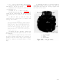
Page 1-1. Paragraph 1-3 is superseded as follows:
1-3. Reporting Errors and Recommending
Improvements
You can help to improve this manual. If you find any
mistakes or if you know of a way to improve the
procedures, please let us know. Mail your letter or
DA Form 2028 (Recommended Changes to Publications
and Blank Forms) direct to: Commander, US Army
Tank-Automotive Command, ATTN: DRSTA-MBP,
Warren, MI 48090. A reply will be furnished to you.
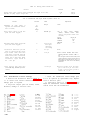
Page 1-4, table 1-2. Add the following nut and bolt
torque data between Ripper and Steering Clutch:
Roll-over Protective Structure:
Heavy duty fender support bolts. . . . . . . . . . . . . . . . . . . .900±100
Tractor frame support bolts . . . . . . . . . . . . . . . . . . . . . . . . . 350±50
Plate-side mounting bolts . . . . . . . . . . . . . . . . . . . . . . . . . .210±30
Page 2-13, paragraph 2-8a. Sub-subparagraph (1.1)
is added as follows:
(1.1) Remove roll-over protective structure (TM 52410-233-20).
1
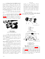
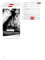
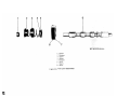
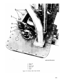
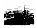
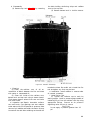
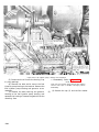
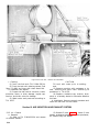
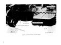
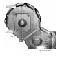
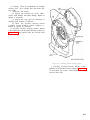
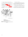
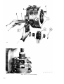
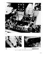
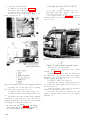
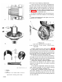
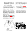
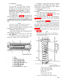
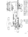
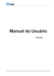
Page 2-15. Figure 2-31.1 (sheet 2 of 6) is added
as follows:
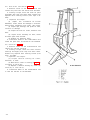
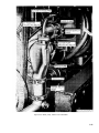
Figure 2-31.1. Preparing to remove engine (w/ROPS) (sheet 2 of 6).
2
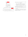
Page 2-20, paragraph 2-9a. Sub-subparagraph (1.1)
is added as follows:
(1.1) Remove roll-over protective structure (TM 52410-233-20).
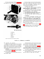
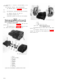
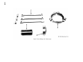
Page 3-4, paragraph 3-12b. Delete subparagraph (3)
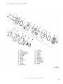
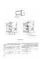
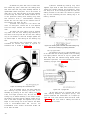
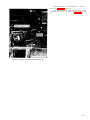
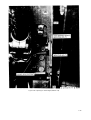
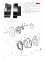
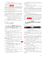
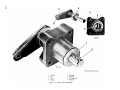
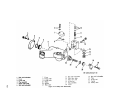
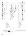
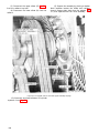
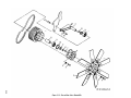
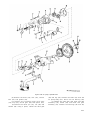
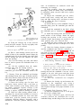
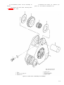
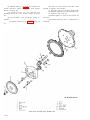
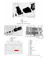
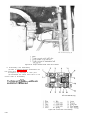
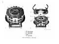
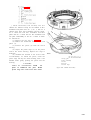
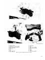
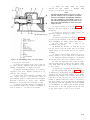
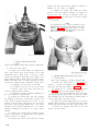
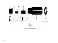
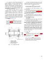
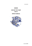
Page 3-5. Figure 3-4 is superseded as follows:
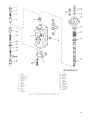
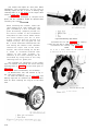
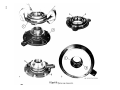
Figure 3-4. Winch hydraulic pump, exploded view.
3
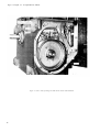
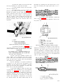
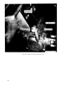
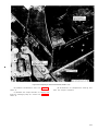
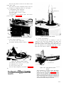
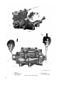
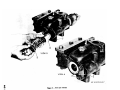
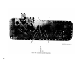
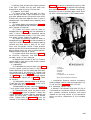
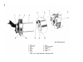
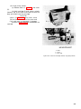
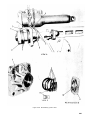
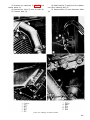
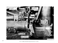
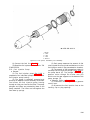
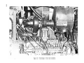
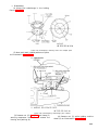
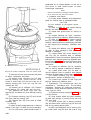
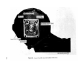
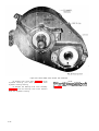
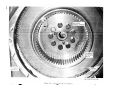
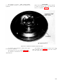
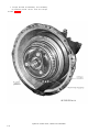
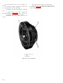
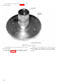
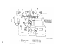
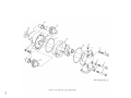
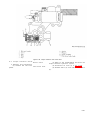
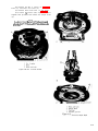
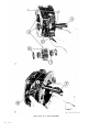
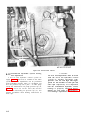
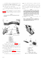
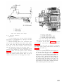
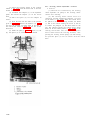
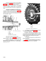
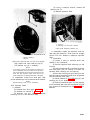
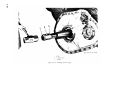
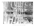
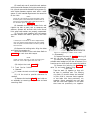
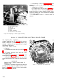
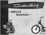
Page 3-8. Figure 3-7. is superseded as follows:
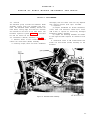
Figure 3-7. Power take off bearing and brake drum, removal and installation.
4
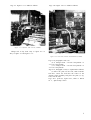
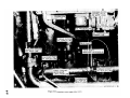
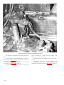
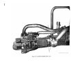
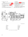
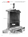
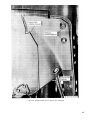
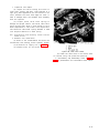
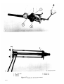
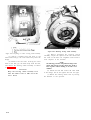
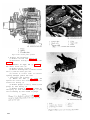
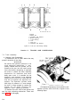
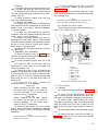
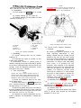
Page 4-3. Figure 4-1.1 is added as follows:
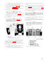
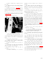
Page 5-30. Figure 5-23.1 is added as follows:
Figure 4-1.1. Hydrailic tank removal (w/ROPS).
Change title of key from “Key to figure 4-1” to
“Key to figure 4-1 and figure 4-1.1”.
Figure 5-23.1. Fuel tank, removal and installation (w/ROPS).
Page 5-54, paragraph 5-27d (10).
(b) is changed from ‘‘170-180 foot-pounds” to
“173-197 foot-pounds”.
(c) is changed from “170-180 foot-pounds” to
“173-197 foot-pounds”.
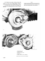
Page 6-75, Paragraph 6-15c(3) is superseded as follows:
(3) Place the plate on the bolt, NSN 5306-00426-4617. Insert the bolt thru the center of the
steering clutch assembly and place the plate (2, fig.
6-86) over the bolt.
Page FO-1 (fold-out), figure FO-1, Chart A. Delete
no. 3, “Quick Drop Valve”.
5
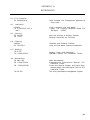
By Order of the Secretary of the Army:
Official:
E. C. MEYER
General, United States Army
Chief of Staff
ROBERT M. JOYCE
Brigadier General, United States Army
The Adjutant General
DISTRIBUTION:
To be distributed in accordance with DA Form 12-25B Direct and General
requirements for Tractor, Tracked: Medium.
6
Support Maintenance
*TM
TECHNICAL MANUAL
NO.
5-2410-233-34
HEADQUARTERS
DEPARTMENT OF THE ARMY
WASHINGTON, D.C., 12 October 1971
5-2410-233-34
DIRECT AND GENERAL SUPPORT MAINTENANCE MANUAL
TRACTOR, FULL TRACKED, LOW SPEED, DED
MEDIUM DRAWBAR PULL:
OSCILLATING
TRACK,
(CATERPILLAR
78-IN.
MODEL
GAGE
D7F)
FSN 2410-177-7283 W/RIPPER
FSN 2410-177-7284 W/WINCH
Paragraph
List
of
CHAPTER
Section
Illustration
.
.
.
.
.
.
1.
I N T R O D U C T I O N
I.
General
II.
CHAPTER
.
2.
.
.
.
.
.
.
I.
II.
CHAPTER
Section
CHAPTER
Section
CHAPTER
Section
parts,
special
.
.
.
.
.
General
Maintenance
IV.
Removal
and
R E P A I R
O F
I.
Bulldozer
.
.
II.
Ripper
.
III.
Winch
R E P A I R
I.
Hydraulic
.
.
.
.
.
.
.
.
.
.
.
.
.
.
.
Page
.
.
.
.
.
.
.
.
.
.
.
.
.
.
.
.
S U P P O R T
.
.
.
.
.
.
.
.
.
.
.
.
.
.
.
.
.
.
.
.
.
.
.
.
.
.
.
.
.
.
.
.
.
.
.
.
.
2-1
.
.
.
.
.
.
.
.
.
2-3
2-1
.
.
.
.
.
.
.
.
2-5
2-3
.
2-7
2-13
.
.
.
.
.
.
.
.
.
.
W I N C H
.
.
.
.
.
.
A N D
.
.
.
.
.
.
.
.
.
.
.
.
.
E Q U I P M E N T
.
.
.
.
.
.
.
.
.
.
.
.
.
.
.
.
.
.
.
.
.
.
.
.
3-1
3-1
.
3-5
3-3
.
3-10
3-4
4-1
.
.
.
.
S Y S T E M
.
4-1
4-3
4-4
III.
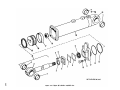
Hydraulic cylinders . . . . . . . . . . .. . . . . . . . . . . . . . . . . . . . . . .. . . . . . .. . . . . . . .. . . . .. . . . .. .
4-8
4-33
R E P A I R
Cooling
O F
T H E
.
.
P O W E R
.
.
.
.
.
.
.
.
.
.
.
.
.
.
.
P L A N T
III.
Air
.
.
5-15
5-30
IV.
Electrical
.
.
5-19
5-42
Engine lubricating system . . . . . . . . . . . . . . . . . . . . . . . . . . . . . . . . . . . . . . . . . . . . . . . . . . . . .
5-23
5-49
Diesel
.
5-26
5-54
6-1
6-1
,
6-13
6-68
.
6-19
6-89
.
.
.
system
.
.
.
.
5-1
exhaust
.
.
5-20
.
.
.
5-1
engine
.
.
5-9
and
.
.
.
system
.
.
.
induction
.
.
.
VI.
.
.
Fuel system . . . . . . . . . . . . . . . . . . . . . . . . . . . . . . . . . . . . . . . . . . . . . . . . . . . . . . . . . .
V .
system
.
.
Hydrulic control valves and hydraulic pump . . . . . .. . . . . . . . . . . . . . . . . . . . . . . . . . . . . . . . . . . . . . . . . . . . . . . .
I.
.
.
.
.
.
.
.
.
components
.
.
.
.
.
.
II.
5.
.
.
.
.
.
.
.
.
.
major
H Y D R A U L I C
.
.
M O V I N G
.
.
O F
tank
equipment
.
of
.
.
.
G E N E R A L
and
.
E A R T H
.
.
.
4.
.
installation
3.
.
.
I N S T R U C T I O N S
tools
.
.
.
2-1
A N D
.
.
1-1
Repair
.
.
1-1
Troubleshooting
.
.
1-1
III.
II.
CHAPTER
Section
.
1-4
S U P P O R T
.
.
.
M A I N T E N A N C E
Section
.
Description and data . . . . . . . . . . . . . . . . . . . . . . . . . . . . . . . . . . . . . . . . . . . . . .
D I R E C T
.
.
.
.
.
.
.
.
.
.
.
.
.
.
.
.
.
.
.
.
.
.
.
.
.
.
.
.
.
.
.
.
.
.
.
.
.
.
.
.
.
.
.
.
.
.
.
.
.
.
.
.
.
.
.
.
.
.
.
.
.
.
.
.
.
.
.
.
.
.
.
.
.
.
.
.
.
.
.
.
.
.
.
.
.
.
.
.
.
.
.
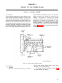
.
.
.
.
.
.
.
.
6.
R E P A I R
I.
Torque divider and transmission . . . . . . . . . . . . . . . . . . . . . . . . . . . . . . . . . . .
II.
III.
Steering
Final
O F
D R I V E
clutches,
drive
.
.
brakes
.
.
.
.
T R A I N
and
.
.
bevel
.
.
.
gear
.
.
.
.
.
.
.
.
.
.
.
.
.
.
.
.
.
.
.
.
.
.
.
.
.
.
.
.
.
.
.
.
.
.
.
.
.
.
.
.
.
.
.
.
.
.
.
i
Page
Paragraph
C HAPTER
Section
7.
REPAIR
I.
General . . . . . . . . . . . . . . . . . . . . . . . . . . . . . . . . . . . . . . . . . . . . . . . . . . . . .. . . . . . . . . . . . . . . . . . . . . . . . . . . . . . . . . . . . . .
II.
III.
A PPENDIX
INDEX
ii
.
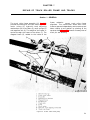
.
TRACK
ROLLER
FRAME
AND
TRACKS
7-1
Track assembly . . .. . . . . . . . . . . . . . . . . . . . . . . . . . . . . . . . . . . . . . . . . . . . . . . . . . . . . . . . . .. .
7-1
7-2
Equalizer bar and track roller frame. . . . . . . . . . . . . . . . . . . . . . . . . . . . . . . . . . . . . .
7-9
7-9
REFERENCES
A.
.
OF
.
.
.
.
.
.
.
.
.
.
.
.
.
.
.
.
.
.
.
.
.
.
.
.
.
.
.
.
.
.
.
.
.
.
.
.
.
.
.
.
.
.
.
.
.
.
.
.
.
.
. . .
.
A-1
I-1
LIST
OF
ILLUSTRATIONS
Number
Title
1-1
Electrical
2-1
Lifting
2-2
Lifting
2-3
Pulley
2 - 4
Bearing
2 - 5
Installing
system
schematic
2-3
eyelet
2-3
2-4
assembly
pulling
Locked
Chamfer
2 - 8
Floating seal
2 - 9
Floating
2-10
Floating
a
2-5
shaft
2-5
installation
seals
installation
installe d
with
2-6
tool
metal
floating
ring
seal
and
toric
sealing
ring
2-6
positioned
2-6
2-11
L i p - t y p e
2-12
Heel
2-13
Elbow
2-14
Sleeve
2-15
Sleeve
2-16
Shear-type
2-17
Removing
bolt
2-18
Hydraulic
cylinder
Cylinder
head
seals
Three
cylinder
head
s e a l
and
seals
2-7
assembly
2-8
toe
type
body
type
2-8
fitting
and
insert-type
2-8
fitting
2-9
fitting
seal
retainer
Removing
cylinder
and
head
2-23
Measuring
cylinder
2-24
Solid
seal
assemblies
installed
2-25
Seal
on
expander
.
2-26
Compressing
2-27
Pump
2-28
Ring,
rotor
2-29
Back-up
ring
Typical
pump
.
.
.
.
.
.
.
.
.
.
.
.
.
.
.
.
.
.
.
.
.
.
.
.
.
.
.
.
.
.
.
.
.
.
.
.
.
.
.
.
.
.
.
.
.
.
.
.
.
.
.
.
.
.
.
2-10
.
.
2-10
.
.
.
piston
.
.
.
.
.
.
.
.
.
.
.
.
.
.
.
.
.
.
.
.
.
.
.
.
.
.
.
.
.
.
.
.
.
.
.
.
.
.
.
.
.
.
.
.
.
.
.
.
.
.
.
.
.
.
.
.
.
.
.
.
.
.
.
.
.
.
.
.
.
.
.
.
.
.
.
.
.
.
.
.
.
.
.
.
.
.
.
.
.
.
.
.
.
.
.
.
.
.
.
.
.
.
.
.
.
.
.
.
.
.
2-11
.
2-11
.
2-11
.
.
.
.
.
.
.
2-12
.
.
.
.
.
.
.
2-12
.
.
.
.
2-13
.
.
2-13
.
.
.
.
.
2-12
installation
.
assembly
.
.
.
.
2-10
.
on
vane
.
.
.
.
.
.
.
.
.
.
.
.
6)
.
.
.
.
.
.
.
.
.
.
.
.
.
.
.
.
.
.
.
.
.
.
.
.
.
.
.
.
.
.
.
.
.
.
.
.
.
.
.
.
.
.
.
.
.
.
.
.
.
.
Preparing
2-31
Preparing
2-31
Prepaing
.
.
.
2-32
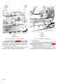
Engine removal . . . . . . . . . . . . . . . . . . . . . . . . . . . . . . . . . . . . . . . . . . . . . . . . . . . . . . . . . . . . . . . . . . . . . . . . .
2-20
2-33
Preparing
to
remove
transmission
(Sheet
1
of
3)
.
.
.
.
.
.
.
.
.
.
.
.
.
.
.
.
.
.
.
.
.
.
.
.
.
.
.
.
.
.
.
.
.
.
.
2-21
Preparing
to
remove
transmission
(Sheet
2
of
3)
.
.
.
.
.
.
.
.
.
.
.
.
.
.
.
.
.
.
.
.
.
.
.
.
.
.
.
.
.
.
.
.
.
.
.
2-22
Preparing to remove transmission (Sheet 3 of 3) . . . . . . . . . . . . . . . . . . . . . . . . . . . . . . . . . . . . . . .
2-23
3 - 1
Bulldozer assembly . . . . . . . . . . . . . . . . . . . . . . . . . . . . . . . . . . . . . . . . . . . . . . . . . . . . . . . . . . . . . . . .
3-1
3 - 2
Scarifier
3 - 3
Hydraulic
2-14
remove
engine
(Sheet
to
remove
engine
(Sheet
3
of
6)
2-16
to
remove
engine
(Sheet
4
of
6)
2-17
to
remove
engine
(Sheet
5
of
6)
2-18
engine
(Sheet
6
of
6)
2-19
to
.
remove
.
.
.
cylinder,
3 - 4
Winch
3 - 5
Control
valve
3 - 6
Winch
control
3 - 7
Power
hydraulic
.
.
link
pump,
.
.
arm,
.
valve,
.
.
.
exploded
take-off
.
.
.
.
view
.
bearing
.
.
beam
view
.
.
and
exploded
removal.
.
of
.
.
Preparing
2
.
.
2-31
3-10
.
.
2-31
3 - 9
of
.
Preparing
3 - 8
1
.
2-31
2-33
(Sheet
.
Preparing
to
engine
.
2-31
2-33
remove
.
.
.
installation
to
.
clearance
.
.
and
.
shims
.
.
2-9
ends
installed
head
seals
head
2-9
Packing
cartridge
and
.
2-22
shims
2-9
spring
rod
2-21
2-30
2-5
bearing
shouldered
seal
properly
2-4
locks
anti-friction
on
2-4
attachment
metal
2 - 7
2-20
1-2
diagram
beam
2-6
2-19
Page
.
.
.
.
.
.
.
.
.
.
carrier
.
.
removal
.
.
.
2-15
.
assembly
.
.
6)
.
.
.
.
.
.
and
.
.
.
.
and
.
.
.
.
.
.
.
.
.
.
brake
.
.
.
.
installation
.
.
.
.
.
.
.
.
.
.
.
.
.
.
.
drum,
.
.
.
.
.
.
.
.
.
.
.
.
.
.
.
.
.
.
3-2
.
3-3
3-5
.
.
.
.
.
.
.
.
.
.
.
.
.
.
.
.
.
.
.
.
.
.
.
.
.
.
.
.
.
.
.
.
3-6
.
.
.
3-7
.
3-8
.
.
.
.
removal
.
.
and
.
.
.
installation
.
.
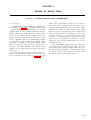
Brake shaft removal . . . . . . . . . . . . . . . . . . . . . . . . . . . . . . . . . . . . . . . . . . . . . . . . . . . . . . . . . . .
Bearing
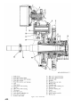
gear
shaft,
cross
sectional
.
.
.
.
.
.
.
.
.
.
.
.
.
.
.
.
.
.
.
.
3-9
.
3-10
.
3-10
.
3-10
.
.
3-11
.
3-11
3-11
3 - 1 5
Clutch
.
3-11
3 - 1 6
Hydraulic clutch . . . . . . . . . . . . . . . . . . . . . . . . . . . . . . . . . . . . . . . . . . . . . . . . . . . . . . .
3-12
3 - 1 7
Hydralic
.
3-12
3 - 1 8
Bevel
gear
3 - 1 9
Pinion
depth
4 - 1
Hydraulic
4 - 2
4 - 3
separator
clutch,
plates
exploded
.
.
.
.
view
.
.
.
.
.
.
.
.
.
.
.
.
.
.
.
.
.
.
.
.
.
.
.
.
.
.
.
.
.
.
.
.
.
.
.
.
.
.
.
.
.
.
.
.
.
.
.
.
.
.
.
.
.
.
.
.
.
.
.
.
.
.
.
.
.
.
.
.
.
.
.
.
.
.
.
.
.
.
.
.
.
.
.
.
.
.
.
.
.
.
Drum shaft removal . . . . . . . . . . . . . . . . . . . . . . . . . . . . . . . . . . . . . . . . . . . . . . . . . . . . . . . . . . . . . . . . . . . . . .
.
.
.
.
.
3 - 1 4
.
.
.
.
.
removal
removal
.
.
.
Bearing
pinion
.
.
.
3 - 1 3
drum
.
.
.
Intermediate
.
.
.
3 - 1 2
.
.
.
shaft
.
.
.
clutch
.
.
.
and
.
.
.
gear
removal
.
.
Bevel
retainer
removal
.
Bearing
and
gear
.
3 - 1 1
gear
drive
view
.
.
.
.
.
.
.
.
.
.
.
.
.
.
.
.
.
.
.
.
.
.
.
.
.
.
.
.
.
.
.
.
.
.
.
3-13
.
.
.
.
.
.
.
.
.
3-14
.
.
.
4-2
Preparing to disassemble tank . . . . . . . . . . . . . . . . . . . . . . . . . . . . . . . . . . . . . . . . . . . . . . . . . . . . . . . . . . . .
4-3
Filter
4-4
shaft
.
tank
inlet
line
.
.
removal
.
.
.
.
.
disconnect
.
.
.
.
.
.
.
.
.
.
.
.
.
.
.
.
.
.
.
.
.
.
.
.
.
.
.
.
.
.
.
.
.
.
.
.
.
.
.
.
.
.
.
.
.
.
.
.
.
.
.
.
.
.
.
.
.
.
.
.
.
.
.
.
.
.
.
.
.
.
.
.
.
.
.
.
.
.
.
.
.
.
.
.
.
.
.
.
.
.
.
.
.
.
.
.
.
.
.
iii
Page
Number
4-4
Bulldozer
4-4
Bullsdozer
4-5
Valve
spool
removal
4-6
Valve
spool
disassembled
removal
and
ripper
and
control
ripper
valves
control
(Sheet
valves
1
of
(Sheets
2)
2
of
4 - 5
4 - 6
2)
4 - 8
4 - 9
4-7
Check
valve
4-8
4-9
Make
up
Makeup
4-10
Control
lever
assembly
(Sheet
1
of
2)
4-16
4-l0
Control
lever
assembly
(Sheet
2
of
2)
4-17
4-11
Control
4-12
Measuring
4-13
Bulldozer
4-14
Relief
valve
4-15
Ripper
control
valve
4-11
body
valve
lever
tilt
Blade
Tilt
removal
4-18
T i l t
4-19
Cover
4-20
Cartridge
4-21
Cover
4-22
Cartridge
4-23
Shaft,
4-24
Disconnecting
valve
manifold
control
and
valve
small
pump
pump
section
4-30
pump
4-31
section
4-32
large
bearing
piston
cylinder
4-26
Preparing
4-27
Disassembling
4-28
Relief
4-29
Driver
dimensions
rod
Piston
4-33
Seal
4-34
Removing
4-35
Tilt
4-36
Preparing
4-37
Removing
to
pump
removal
4-33
rod
4-34
4-34
disassemble
piston
and
cylinder
4-35
head
4-36
removal
4-36
4-36
bearing
assembly
4-37
4-37
clearance
reassembly
assembly
4-38
installation
cylinder
4-38
4-39
removal
to
4-40
disassemble
cylinder
4-36
nut
4-42
4-38
Disassembling
Measuring
4-40
Removing
4-41
Ripper
lift
5-1
Cooling
system
5-2
Hood,
piston
5-3
Preparing
5-4
Lifting
5-5
Radiator
5-6
Radiator
5-7
Fan
5-8
Bulldozer
5-9
Radiator
5-10
Lifting
5-11
Fan
head
4-43
clearance
4-44
shims
4-44
cylinder,
to
exploded
schematic
headlight
remove
view
4-45
diagram
brackets
radiator
and
5-1
radiator
top
guard,
removal
and
installation
5-2
radiator
from
5-3
radiator
guard
5-4
disassembly
bottom
adapter
and
lift
fan
drive
and
and
Water
pump,
removal
5-13
Water
pump,
exploded
5-14
Engine
5-15
Fan
cooler,
fan
removal
drive,
5-18
Fuel
injection
pump,
5-19
Fuel
injection
pump,
5-20
Engine
5-21
Fuel
transfer
5-22
Fuel
transfer
disassembly
speed
tank,
disconnect
removal
and
from
5-8
couplings
5-9
installation
5-11
tractor
5-12
5-15
installation
view
and
and
5-16
installation
.
.
.
.
.
.
.
.
.
.
.
.
.
.
.
.
.
.
.
.
.
.
.
.
.
.
.
.
.
.
.
.
.
.
.
.
.
.
.
.
.
.
.
.
.
.
.
.
.
.
.
.
.
.
.
.
.
.
5-17
.
.
.
5-19
.
.
.
installation
reassembly
removal
.
.
and
exploded
.
5-20
.
.
.
installation
.
.
.
.
.
.
.
.
.
.
.
.
.
.
.
.
.
5-21
.
5-22
5-23
view
exploded
removal
.
and
5-26
view
5-28
installation
5-29
pump
5-23
Fuel
removal
5-24
Air
5-25
Muffler,
5-26
Engine
5-27
Turbocharger,
cleaner
lines
coupling
and
governor,
pump,
5-7
assembly
5-13
injector, removal
Fuel
Fuel
support
radiator
disassembly
5-17
installation
installation
and
5-16
injector,
and
guard,
guard
5-12
and
hydraulic
radiator
removal
oil
removal
cylinder
and
belt
5-5
guard,
radiator
and
tools
shims
4-39
iv
large
4-27
4-29
section
removal
valve
4-32
small
disassembly,
Lift
4-26
removal,
removal,
and
4-24
r e m o v a l
cartridge
4-25
Measuring
removal
disassembly
disassembly,
seal
4-21
4-22
l e v e r
cartridge
and
4-20
disassembly
valve
c o n t r o l
and
4-19
valve
disassembly
4-17
Piston
4-18
clearance
4-16
4-30
4-14
disassembly
relief
4-31
4-13
removal
disassembled
body,
removal
exhaust
flow
and
removal
and
5-30
installation
and
5-31
installation
5-32
installation
diagram
removal
and
.
.
.
.
installation
.
.
.
.
.
.
.
.
.
.
.
.
.
.
.
.
.
5-33
5-34
N u m b e r
Title
Page
5-28
5-35
5-29
5-35
5-30
5-36
5-31
5-37
5-32
5-33
5-38
5-34
5-35
5-41
5-36
5-45
5-36
5-45
5-37
5-50
5-38
5-51
5-39
5-53
5-40
5-55
5-41
5-56
5-42
5-58
5-42
5-59
5-43
5-60
5-44
5-61
5-45
5-62
5-46
5-63
5-47
5-64
5-48
5-65
5-39
5-43
5-49
5-66
5-50
5-68
5-51
5-69
5-52
5-70
5-53
5-72
5-54
5-55
5-73
5-56
5-57
5-76
5-74
5-78
6-1
6-2
6-2
6-3
6-4
6-4
6-6
6-5
6-7
6-6
6-8
6-3
6-7
6-9
6-8
6-10
6-9
6-11
6-10
6-12
6-11
6-13
6-12
6-13
6-13
6-14
6-14
6-15
6-15
6-17
6-16
6-18
6-17
6-19
6-18
6-20
6-19
6-21
6-20
6-23
6-21
6-22
6-25
6-23
6-24
6-26
6-25
6-27
6-26
6-27
6-28
6-28
6-28
6-29
6-29
6-30
6-31
6-31
6-33
6-32
6-34
6-33
6-35
6-34
6-36
6-26
6-27
6-27
v
Page
Title
N u m b e r
relief
Outlet
6-36
Check
6-37
Check
6-38
Clutch operation . . . . . . . . . . . . . . . . . . . . . . . . . . . . . . . . .. . . . . . . . . . . . . . . . . .
6-39
6-39
Clutch
6-39
6-40
Preparing
6-41
Removing
input
6-42
Preparing
to
6-43
Removing transmission case . . . . . . .. . . . . . . . . . . . . . . . . . . . . . . . . .. . . . .. . . . .. . .. . . . .
6-41
6-44
Checking
clutch
6-42
6-45
Preparing
to
remove
6-46
Removing
input
shaft
.
6-42
6-47
Removal of No. 1 and No. 2 clutch . . . . . . . . . .. . . . . . . . . . . . . . . . . . . . . . . . . . . . . .. . . . . . . . . . . . . . . . . . .. . . . .
6-43
6-48
Removing
No.
l
6-49
Removing
No.
3
6-50
No.
carrier
removal
.
6-51
Removing
output
shaft
.
6-52
Preparing
to
6-53
Bearing
cage
6-54
Oil
6-55
Retainer
ring
6-56
Bearing
cage
disassembly
6-57
Bearing
race
and
6-58
No.
4
sun
6-59
No.
l
carrier
disassembly
.
6-60
No.
2
carrier
disassembly
.
6-61
Clutch
6-62
Transfer
6-63
Removing
transfer
6-64
Separating
cages
6-65
Removing
cover
valve
valve
6-36
6-35
removal
valve
assembly
.
.
disassembly
.
.
designation
to
2
seal
.
.
.
remove
.
.
.
shaft
carrier
gear
.
housing
.
.
.
.
.
.
.
.
.
.
.
.
.
.
.
.
.
.
.
.
.
.
.
.
.
.
.
.
.
.
.
.
.
.
.
.
.
.
.
.
.
.
.
.
.
.
.
.
.
.
.
.
.
.
.
.
.
.
.
..
.
.
.
.
.
.
.
.
.
.
.
.
.
.
.
.
.
.
.
.
.
.
.
.
.
.
.
.
.
.
.
.
.
.
.
.
.
.
.
.
.
.
.
.
.
.
.
.
.
.
.
.
.
.
.
.
.
.
.
.
.
.
.
.
.
.
.
.
.
.
.
.
.
.
.
.
.
.
.
.
.
.
.
.
.
.
.
.
.
.
.
.
.
.
.
6-38
.
.
.
.
.
.
.
.
6-43
.
.
6-44
.
6-45
.
.
6-45
.
.
6-46
.
6-46
.
.
.
6-46
.
.
.
6-47
.
.
.
.
.
.
.
.
.
.
.
6-42
..
.
.
.
.
.
.
.
.
.
.
.
.
.
.
.
.
.
.
6-48
.
.
.
.
.
.
.
.
6-50
.
.
.
6-51
.
.
.
.
.
.
.
.
.
.
.
.
.
.
.
..
.
.
.
.
.
.
.
.
.
.
.
.
.
.
.
.
.
.
.
.
.
.
.
.
.
.
.
.
.
.
.
.
.
.
.
.
.
.
.
.
.
.
.
.
.
.
.
.
.
.
.
.
.
.
.
.
.
.
.
.
.
.
.
.
.
.
.
.
.
.
.
.
.
..
.
.
.
.
.
.
.
.
.
.
.
.
.
.
.
.
.
.
.
.
.
.
.
..
.
.
.
.
.
.
.
.
.
.
.
.
.
.
.
.
.
.
.
.
.
.
.
.
.
.
.
.
.
.
.
.
.
.
.
.
.
.
.
.
.
.
.
.
.
.
.
.
.
.
.
.
.
.
.
.
.
.
.
.
.
.
.
.
.
.
.
.
.
.
.
.
..
.
.
.
.
.
.
.
.
.
.
.
.
.
.
.
removal
.
.
.
.
.
.
.
.
.
.
.
.
.
.
.
.
.
.
.
.
.
.
.
.
.
.
.
.
6-40
.
.
.
.
.
.
.
.
.
.
6-40
.
.
.
.
6-41
.
.
.
.
.
.
.
.
.
.
.
..
.
.
.
.
.
.
.
.
.
.
.
.
.
seal
.
.
.
.
.
.
.
.
removal
.
.
.
.
.
.
.
.
.
.
.
.
.
gear
.
.
.
.
.
.
oil
.
.
shaft
.
.
.
.
.
.
.
.
.
.
.
.
.
.
removal
.
.
case
.
.
input
.
.
seal
.
.
.
sun
.
shaft
.
.
clutch
.
.
front
.
input
.
removal
.
oil
operation
removal
.
transmission
removal.
gear
.
front
disassemble
.
shaft
remove
disassembly
.
.
input
6-37
.
.
.
.
.
.
.
.
.
.
.
.
.
.
.
.
.
6-52
.
.
.
.
.
.
.
.
.
.
.
.
.
6-54
.
.
.
.
6-55
.
.
6-56
.
.
.
.
.
.
.
.
.
.
.
.
.
.
.
.
.
.
.
.
.
.
bearings.
.
.
.
.
.
.
.
.
.
.
.
.
.
.
.
.
.
.
.
.
.
.
.
.
6-56
.
.
.
.
.
.
.
.
.
.
.
.
.
.
.
.
.
.
.
.
.
.
.
.
.
.
6-57
.
.
.
.
.
.
.
.
6-59
6-66
Removing bevel pinion . . . . . . . . . . . . . . . . . . . . . . . . . . . . . . . . . . . . . . . . . . . . . . . . . . .
6-60
6-67
Bearing outer race removal . . . . . . . . . . . . . . . . . . . . . . . . . . . . . . . . . . . . . . . . . . . . . .
6-61
6-68
Junction block removal . . . . . . . . . . . . . . . . . . . . . . . . . . . . . . . . . . . . . . . . . . . . . . . .
6-62
6-69
Transmission
6-63
6-70
Hydralic
6-71
Transmission control linkage, exploded view . . . . . . . . . . . .. . . . . . . . . . . . . . . . . . . . .
6-72
Brake operation . . . . . . . . . . . . . . . . . . . . . . . . . . . . . . . . . . . . . . . . . . . . . . . . . . . . .
6-73
Preparing
6-74
Brake
gear
.
outer
.
.
.
.
.
.
.
.
.
hydraulic
control
.
.
control
system
.
.
.
system
pressure
.
.
.
schematic
tap
.
.
(first
.
.
.
.
.
.
.
.
.
.
.
.
foward)
6-65
locations
6-67
6-69
.
6-70
.
6-70
6-75
Brake, engaging mechanism disassembly . . . . . . . . . . . . . . . . . . . . . . . . . . . . . . . . . . . . . . . . . . . . .
6-71
6-76
Brake, lever bearings . . . . . . . . . . . . . . . . . . . . . . . . . . . . . . . . . . . . . . . . . . . . . . . . . . . . . . .
6-72
6-77
Brake
6-78
6-79
Disassembling
Adjusting
brake
engaging
6-80
Adjusting
brake
linkage
6-81
Steering
6-82
Prepaing
6-83
Removing
6-84
Removing
6-85
Cross
6-86
Holding
6-87
Preparing
6-88
Assembling
6-89
Installing
inner
drum.
6-90
Installing
clutch
disc
6-91
Compressing
6-92
Removing steering clutch assembly from inter drum
6-80
6-93
Removing
6-80
6-94
Preparing
6-95
Removing
6-96
Steering
6-97
Pulling
6-98
I n s t a l l i n g
.
6-82
6-99
Steering clutch hydraulic control (side view) . . . . . . . . . . . . . . . . . . . . . . . . . . .. . . . . ........... . . . . . .. . . . . . .. . . . . . . . . . . . . . . . . .. .. .. . .
6-83
6-100
Control piston operation. . . . . . . .. . . . . . . . . . . . . . . . . . . . . . . . . . . . . . . . . . ... . . . .
6-84
6-101
Control valve removal
6-84
6-102
Control
v i
to
remove
engaging
mechanism
adjusting
brake
removal
mechanism
clutch
cover
clutch
to
.
.
.
.
brake
.
.
.
.
.
.
operation
.
steering
clutch
.
steering
to
clutch
clutch
to
hub
hub.
valve
.
.
.
.
.
.
.
.
.
.
.
.
.
.
.
.
.
.
.
.
.
.
.
.
.
.
.
.
.
compression.
.
.
.
.
.
.
assembly
.
.
retainer.
.
.
.
.
.
.
.
.
.
.
.
.
.
.
.
.
.
.
.
.
.
..
.
.
.
.
.
.
.
.
.
.
.
.
.
.
.
.
.
.
.
.
.
.
.
.
.
.
.
.
.
.
.
.
.
.
.
.
.
.
.
.
.
.
.
.
.
.
.
.
.
.
.
.
.
..
.
.
.
.
.
.
.
.
.
.
.
.
.
.
.
.
.
.
6-75
.
.
.
.
.
.
.
.
..
.
.
.
.
.
.
.
.
.
6-76
.
.
.
.
.
.
.
.
.
6-76
.
6-77
6-77
.
.
6-78
.
.
.
.
.
6-78
6-79
.
.
6-79
6-79
.
.
6-80
.
.
.
.
.
.
.
.
.
.
.
.
.
.
..
.
.
.
.
piston
hub
.
retaining
.
assembly
.
hub
6-80
6-81
.
(exploded
view)
6-81
6-81
.
h u b . . . . . . . . . . . . . . . . . . . . . . . . . . . . . . . . . . . . . . . . . . . .
housing
6-74
6-75
.
.
.
.
.
.
.
6-73
.
.
.
.
.
.
.
.
.
6-72
.
.
.
.
.
.
.
.
.
.
.
.
.
.
.
.
.
.
.
.
.
.
.
.
.
.
.
.
.
.
.
.
.
.
.
.
.
.
.
.
.
.
.
.
.
.
.
.
.
.
.
.
.
.
.
.
.
.
.
.
.
.
.
.
.
.
.
.
.
.
.
.
.
.
.
.
.
.
.
.
.
.
.
.
.
.
.
.
assembly
.
to
.
.
.
springs.
clutch
nut.
.
.
.
.
.
.
.
.
.
.
.
.
.
.
.
.
.
.
.
.
.
.
.
.
.
.
.
.
.
.
.
.
.
.
.
.
.
.
.
.
.
.
.
.
.
.
assemblies
hub
.
sleeves
.
remove
clutch
in
clutch
and
retaining
.
.
spring
clutch
steering
.
.
.
.
.
.
.
assembly.
assemble
steering
.
.
assembly
drum.
springs
.
.
.
.
clutch
outer
of
.
.
.
.
steering
section
mechanism
.
.
linkage.
.
remove
.
.
.
mechanism.
.
engaging
disassembly.
.
.
.
.
.
.
.
.
.
.
.
.
6-84
Number
Title
Page
6-103
6-85
6-104
6-85
6-105
6-85
6-106
6-86
6-107
6-86
6-87
6-108
6-109
6-88
6-110
6-88
6-111
6-90
6-112
6-91
6-113
6-92
6-114
6-93
6-115
6-94
6-116
6-94
6-117
6-96
6-118
6-96
6-119
6-97
6-120
6-98
6-121
6-99
6-122
6-100
6-123
6-100
6-124
6-101
6-125
6-101
6-126
6-102
6-127
6-103
6-128
6-103
6-129
6-104
6-130
6-104
6-131
6-105
6-132
6-106
6-133
6-108
6-134
6-109
6-135
6-109
6-136
6-110
6-137
6-111
6-138
6-111
6-139
6-111
6-140
6-111
6-141
6-112
6-142
6-112
6-143
6-113
6-144
6-113
6-145
6-114
6-146
6-114
6-147
6-116
6-148
6-118
7-1
7-1
7-2
7-2
7-3
7-2
7-4
7-3
7-5
7-3
7-6
7-4
7-7
7-4
7-8
7-5
7-9
7-6
7-10
7-6
7-11
7-6
7-12
7-7
7-13
7-8
7-14
7-8
7-15
7-8
7-16
7-9
7-17
7-10
7-18
7-10
7-19
7-11
7-20
7-12
7-21
7-12
v i i
Page
Title
N u m b e r
7-22
7-12
7-23
7-12
7-24
7-25
7-13
7-14
Removing
tension
from
recoil
spring
stops
7-14
7-26
7-27
Removing
7-28
Recoil
7-29
A s s e m b l i n g
7-30
Spring
7-31
7-32
Installing
seal
Preaparing
to
7-33
Removing seal and ring . . . . . . . . . . . .
7-16
7-34
Cylinder
7-17
7-35
Relief
7-30
Preparing
7-37
Removing
7-38
Removing
7-39
Removing
7-40
Bearing cap assembly . . . . . . . . . . . . . . . . . . . . . . . . . . . . . . . ..
FO-1
Hydraulic flow schematic diagram . . . . . . . . . . . . . . . . . . . . . . . . . . . . . . . . . . . . . . . . . . . . . . . . . .
v i i i
recoil
recoil
spring
spring
bolt
stops
assembly
r e c o i l
guide
pin.
and
.
.
.
.
7-14
7-15
a s s e m b l y
.
.
7-15
...
ring.
remove
.
.
7-16
.
cylinder.
.
.
.
.
.
.
.
.
.
.
.
.
.
.
.
.
.
.
.
.
.
7-16
assembly
valve
and
to
remove
outer
diagonal
track
roller
fill
valve
support
bearing
brace
frame
.
.
.
.
assembly
.
.
cap
.
bearing
.
.
.
.
.
.
.
.
.
.
.
.
.
.
.
.
.
.
.
.
.
.
.
.
.
.
7-17
.
7-18
.
7-19
.
7-19
7-18
.
.
.
.
.
.
cap
.
7-16
.
.
.
.
.
.
.
.
.
.
.
.
.
.
.
.
.
.
.
.
.
.
.
.
.
.
.
.
.
.
.
.
.
.
.
.
.
.
.
.
.
.
.
.
.
.
.
.
.
.
.
.
.
.
.
.
.
.
.
.
.
7-19
FO-1
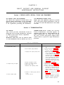
CHAPTER
1
INTRODUCTION
Section
I.
GENERAL
1-1. Scope
maintenance levels are listed in and prescribed by
This manual contains instructions for the use of
direct and general support maintenance personnel
maintaining the Caterpillar Model D-7F Tractor as
TM
allocated by the Maintenance Allocation Chart. It
provides information on the maintenance of the
equipment which is beyond the scope of tools,
equipment, personnel, or supplies normally
available to organizational level maintenance
personnel.
1-2. Maintenance Forms and Records
Maintenance forms, records and reports which are
to be used by maintenance personnel at all
38-750.
1-3. Reporting of Errors
recomand
R e p o r t i n g o f e r r o r s , omissions,
mendations for improving this publication by the
individual user is encouraged. Reports should be
submitted
on
DA
Form
2028
(Recommended
Changes to Publications) and forwarded direct to
Commanding General, U . S . A r m y M o b i l i t y
Equipment Command, A T T N : A M S M E - M P P ,
Blvd., St.
Louis, Mis4300 Goodfellow
souri 63120.
Section Il. DESCRIPTION AND DATA
1-4. Description
A general description of the Model D-7F tractor
and plates is contained in TM 5-2410-233-10. A
more detailed description of specific components
and assemblies is contained in the applicable
sections of this manual. Detailed descriptions of the
components o f t h e M o d e l D - 7 F t r a c t o r a r e
provided in the applicable maintenance paragraphs
of this manual.
1-5. Differences Between Models
This manual covers only the Caterpillar Model
D7F Tractor. No known differences exist for the
Model covered by this manual.
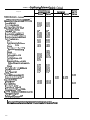
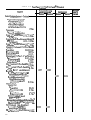
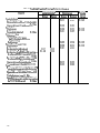
b. Nut and Bolt Torque Data. Tables 1-1 and 12 list the standard and specific nut and bolt torque
data for the D7-F tractor.
c. Repair and Replacement Standards. Tables 13, 1-4, and 1-5 list manufacturer’s dimensions,
tolerances, clearances, and the maximum allowable
wear clearance.
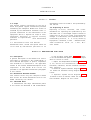
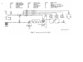
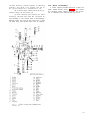
d. Electrical System Schematic Diagram. F i g u r e
1-1 shows the schematic wiring diagram for this
tractor.
e. Hydraulic System Circuit Diagram. F O - 1
(Located in back of manual) shows the hydraulic
flow schematic diagram for this tractor.
1-6. Tabulated Data
a. Identification. The major identification plates
of the tractor are described in TM 5-2410-233-20.
1-1
1-2
Figure 1-1.
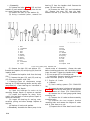
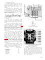
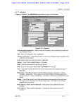
T a b l e 1 - 1 . Standard Torques
Bolts and Nuts
Size
(inches)
¼
5 / 1 6
3/8
16
½
9/16
5/8
Torque
(ft-lbs)
Torque
(ft-lbs)
Size
(inches)
9±3
18 ± 5
32± 5
¾
7/8
1
1 1/8
1¼
1%
1½
50 ± 10
75 ± 10
110 ± 15
150 ± 20
265
420
640
800
1000
1200
1500
±
±
±
±
35
60
80
100
± 120
± 150
± 200
110
170
260
320
400
480
550
±
±
±
±
±
±
±
Taper lock Studs
¼
5/16
3/8
7/16
½
9 / 1 6
5/8
5±2
¾
10 ± 3
20±3
30 ± 5
7/8
1
1 1/8
40 ± 5
60 ± 10
75 ± 1 0
1¼
1:%
1½
15
20
30
30
40
40
50
Hydraulic Valve Bolts and Nuts
5/16
3/8
7/16
13 ± 2
24 ± 2
30 ± 2
60±3
118 ± 4
½
5/8
T a b l e 1 - 2 . Specific Nut and Bolt Torque Data
Item
Lb-Ft
Cylinder head:
(first time) . . . . . . . . . . . . . . . .
(second
time)
. . . . . . . . .
. . .
(third
time)
. . . . . . . . . . .
Accessory
drive
retainer
nut
torque
Camshaft gear retainer bolt torque . . . . . . . .
Connecting rod bolt nuts torque . .
. . . . . . . . . . . . 115
. . . . . . . . . . . . . 175 ± 5
. . . . . . . . . . . . . . . 175 ± 5
.
.
.
.
.
90-110
. . . .
.
.
. 1 4 - 2 0
. . . . . . . . . .. . . . . . . . . . .30 ± 3 (plus additional
turn of 90°)
Main bearing bolt torque . . . . . . . . . . . . . . . . . .. . . . . . . . . . . .30 ± 3 (plus additional
turn of 90°)
Crankshaft
pulley retaining
screw torque.
.
.
.
.
.
.
210-250
Flywheel
retaining
bolt
torque.
. . . . . . . . . . 130-170
Flywheel housing bolt
and
nut torque . . . . . . . . . 65-85
Fuel injection line nut torque. . . . . . . . . . . . . . . 25-35
Fuel injection nozzle retaining nut torque . . . . . . . . . . . . . . . . 105 ±
5
Fuel injection precombustion chamber torque . . . . . . . .. . . . .. 140-160
Fuel
transfer
pump
shaft
retaining
nut
torque
17-27
Fuel injection p u m p r e t a i n i n g b u s h i n g . . . . . . . . . . . 150 ± 1 0
Timing gear housing bolt torque... . . . . . . . . . . . . . . . . . . . . 27-37
Turbo charger:
T o r q u e o n h o u s i n g b a n d c l a m p . . . . . . . . . . . . . . . . . . . . 120 l b - i n
Torque on impeller nut . . . . . . . . . . . . . . . . . . . . . . . . . . . . . . . . . . . . . . . . . . 15 ± 1
Turbocharger to manifold bolt.... . . . . . . . . . . . . . . . . . . 36-44
Water pump impeller retaining bolt torque . . . . . . . . . . . . . . 27-29
Torque divider:
Scavenge pump:
Drive gear-to-shaft retaining nut torque . . . . . . . . . . . . . . . . 36-44
Transmission
hydraulic
controls:
Control valve-to-transmission retaining bolt, torque . . . . . . . . . . . . . . . . . . . 32-38
Safety valve-to-directional valve, torque (installed using liquid lock) 35-45
Pressure
control
valve
cover-to-body
retaining
bolts,
torque
32-38
Transmission:
Clutch, housing
retaining
bolts....
. . . . . . . . . . . . . . . . . . . . . . . . . . . . . . . . 80-90
Transmission
case
to
tranafer
gear
case
retaining
nut
70-80
Bearing cage to
No.
1 carrier retaining bolt . . . . . . 37-43
Bearing cage to No. 2 carrier retaining bolts . . . . . . . . . . . . . . . . . . . . . . . . . 37-43
1-3
Table
1 - 2 . Specific Nut and Bolt Torque Data—Continued
Lb-Ft
Item
Bevel gear:
Hub to drum
bolts.
. . . . . . . . . . . . . . . . . . . . . . . . . . . . . . . . .
Hub to bevel gearshaft retaining nut . . . . . . . . . . . . . . . . . . . . . . . . . . . . . . . . . . .
Ripper:
Mounting bracket stud nut. . . . . . . . . . . . . . . . . . . . . .. . . . . . . . . . .
Hydraulic cylinder piston rod nut. . . . . . . . . . . . . . . . . . . . . . . . . .. . . . .
Steering clutch:
Steering clutch hub-to-steering clutch inner drum bolt, torque .. . . . . . . .
Glow
plug
. . . . . . . . . . . . . . . . . . . . . . .
Steering clutch outer drum-to-pinion flange bolt torque. . . . . . . . . . . . . .
Final drive:
Track roller frame outer bearing retaining nut torque. . . . . . . . . . . . . . . . .
Final drive case-to-steering clutch and bevel gear case bolt, torque. . . . . . . . . . . . . . . . . . . . . . .
Final
drive
flange-drum screw . . . . . . . . . . . . . . .
Track rollers mounting bolt..... . . . . . . . . . . . . . . . . . . . .
Lubrication plug, torque.. . . . . . . . . . .. . . . . .. . . . . . . . .
Front idlers and recoil springs:
Taper lockpins bolt torque:
Initial to seat parts. . . . . . . . . . . . . . . . . . . . . . . . . . . . . . . . . . .
Hammer lock pins into place, then tighten to torque value of . . . . . . . . . . .
Lubrication
plug
torque
. . . . . . . . . . . . . . . . . . . . . . . . . . . . . . . . . . . . . . . .
Fill valve torque . . . . . . . . . . . . . . . . . . . . . . . . . . . . . . . . . .
Ball
check
valve
to torque . . . . . . . . . . . . . . . . . . . . .
Relief valve torque . . . . . . . . . . . . . . . . . . . . . . . . . . . . . .
Track:
Track shoe bolt torque. . . . . . . . . . . . . . . . . . . . . . .
Minimum torque after 120°turn. . . . . . . . . . . . . . . . . . . . . . . . . . . . . . . .
200
700
1500
1600
±
±
20
100
±
120
180-220
120 ± 24 lb-in.
180-220
500-600
200-220
180-220
550 ± 50
110-140
65
50 ± 10
110-140
20-30
20-30
20-30
180-260
420
(plus
additional
120°)
T a b l e 1 - 3 . Engine Repair and Replacement Standards
Component
Manufacturer’s dimensions
and tolerances in inches
Desired clearance
Maximum
Maximum
ACCESSORY DRIVE SHAFT:
Backlash between accessory drive and accessory
drive idler gear
Backlash between accessory drive and idler gear
and camshaft gear
CAMSHAFT:
Bearing journal diameter
Bearing clearance
End clearance
CONNECTING ROD:
Connecting rod bearing clearance (measured
vertically)
Center to center distance
Piston pin bearing should be machined to ID of
CRANKSHAFT:
Main journal diameter
Main bearing clearance
End clearance
Connecting rod journal diameter
Permissible journal wear
Permissible out-of-roundness (journal)
CYLINDER BLOCK:
Main bearing original bore dimension
Camshaft bearing bore
1-4
0.002
0.014
0.002
0.014
2.3105
2.3115
9.594
1.7009
9.596
1.7015
3.499
3.500
2.999
3.000
3.8155
2.5625
3.8165
2.5635
Maximum
allowable
wear and
clearance
0.002
0.004
0.006
0.010
0.008
0.025
0.0042
0.0071
0.010
0.0030
0.0025
9.0059
0.0145
0.0008
0.010
0.005
0.008
0.008
0.004
Table 1-3. Engine Repair and Replacement Standards-Continued
Marrutacturer’s
dimensions
and tderanfes in inches
Madrmm
Dcair’ddarance
attow*Ma
wear and
Maximum
CYLINDER LINER:
Inside diameter
Permissible liner wear (increase
in diameter at
top of ring travel)
Liner flange thickness
Counterbore dimension in block
FUEL INJECTION EQUIPMENT:
Fuel injection pump timing (before top center)
13° 30
Fuel injection pump lifter setting (On engine
with
8S7167 Gauge) 4.2179 ± .0020
Fuel injection pump lifter setting (off engine)
4.2675 ± .0005
Fuel pump plunger length
Permissible wear (decrease in length of plunger)
Fuel injection camshaft bearing bore
Camshaft bearing clearance
FUEL TRANSFER PUMP:
Clearance
between gears and covers, total
Bearing bore
Bearing clearance
GOVERNOR:
Backlash between bevel drive and driven gears
Clearance between top cover bearing and shaft
Dimension (X)-see test 2.12.5-2.145
Decelerator l o w
i d l e speed adjustment 600700 rpm
Oil PUMP:
Clearance between gears and end covers
Drive gear shaft diameter
Bearing bore
PISTON PINS:
Pin bore
PISTON
KINGS:
PISTON ring side clearance:
Top ring
2d ring
Oil ring
Ring gap, top
Ring gap, 2d
Ring gap, oil
REAR
POWER
TAKEOFF
AND PUMP
DRIVE:
Backlash
Oil pump drive gear to oil pump
driven gear
Power takenff shaft drive gear
to camshaft gear
Bearing clearance
End clearance
ROCKER ARMS:
Bore bearing
Shaft diameter
Maximum permissible clearance (bearing-shaft)
SERVICE METER:
Permissible bearing clearance
TURBOCHARGER:
Clearance between impeller and bearing
housing (shaft pushed toward impeller end)
End clearance
Bearing diameter (ID)
Bearing diameter (OD)
4.750
4.752
0.4040
0.400
0.4056
0.402
2.5931
2.5937
1.875
1.876
Mirrirnrsm
Maximum
Ctearanca
0.008
0.005
0.010
0.4950
0.8745
0.743
0.7260
0.7240
0.001
0.003
0.001
0.002
0.005
0.002
0.001
0.006
0.003
0.005
0.002
0.004
0.0020
0.0035
0.006
1.6999
1.7003
0.0025
0.0028
0.023
0.0015
0.017
0.017
0.013
0.0046
0.0041
0.0033
0.023
0.023
0.023
0.007
0.002
0.016
0.003
0.003
0.010
0.016
0.006
0.020
0.4956
0.8749
0.744
0.010
0.035
0.7266
0.7250
0.008
0.012
0.020
0.0045
0.6880
0.8718
0.022
0.0015
0.6883
0.8722
0.008
0.006
1-5
Table 1-3. Engine Repair and Replacement Standards-Continued
Component
Manufacturer’s dimenalom
and toleranma in Inched
Minimum
Maximum
third deamnce
Minium
Maximum
0.025
0.015
0.025
0.015
hfaxlmum
allowable
wear and
c.learanu
TURBOCHARGER—Continued
Note. Bearing clearance is satisfactory if compress or
wheel and/or turbine wheel have not rubbed governor housing
Journal diameter
Housing bore diameter
Thickness of thrust bearing
VALVE AND VALVE SEAT
SPECIFICATIONS:
Valve seat angle2
Inlet valve seat insert diameter
Bore for inlet valve seat insert
Exhaust valve seat insert diameter
Bore for exhauat valve seat insert
Valve head diameterInlet
Exhaust
Outside diameter of valve seat
face
(new)-inlet
Exhaust
outside diameter of valve seat
face (after reconditioning)
Inlet
Exhaust
Stem diameter
Valve guide bore-inlet
Exhaust
Valve lip thickness-inlet
Exhaust
Measurement from top of valve
to face of head with valve seatedinlet
Exhaust
Depth of bure for valve seat inserts
Valve seat width-inlet
Exhaust
Valve face angle2
VALVES:
Valve stem clearance in guide
Exhaust valve clearance (hot)
Inlet valve clearance (hot)
VALVE LIFTERS:
Lifter diameter
Bearing bore
VALVE SPRING:
2.05 in.
Free length
54.8-6Q
Pounds force
1.766 in.
When compressed to
Outside diameter
1.386 in.
WATER TEMPERATURE
REGULATOR:
Opening temperature
164° - 166°
Fully open temperature 180°
0.5612
0.8762
0.210
0.5615
0.8767
0.212
30°
2.1280
2.1250
2.0030
2.0000
30°
2.1290
2.1260
2.0040
2.0010
2.015
1.891
2.025
1.901
1.934
1.810
1.984
1.860
0.3712
0.3736
0.3736
0.057
0.070
0.088
0.111
0.448
0.030
0.030
29¼°
1.984
1.860
0.3722
0.3756
0.3756
0.134
0.157
0.450
0.076
0.076
29¼°
0.009
1.3100
1.3135
1.3110
1.3155
1 Maamre valve gutda bom In potion of gutda wtdch Is pmaaed Into cyttndw head clocoat to vatve head.
2 M vatva seat face excwda tha maxtmunr wtdth ● ftar grhultng, narrow the seat fsce by uItng 18° stone or fly cutter,
1-6
0.010
Table 1-4. Power Transmission Unite Repair and Replacement Standards
Torque Divider:
Engine rpm at torque converter stall 755-885
Converter type single stage
21 in.
Converter size
Clearance between torque converter stator and
turbine (see text for correct method of
measuring)
Clearance between torque converter stator and
impeller, (see text for correct method of
measuring
Torque Converter Inlet Relief Valve:
Mounting location Directional valve housing
within transmission
(BENCH TEST ONLY)
4-6 gpm
Set to bypass
135-145 psi
At pressure of
Inlet relief valve spring:
.476-.558 lb.
Test force
.48 in.
When compressed to
.89 in.
Free length after test
.300 in.
Spring diameter
Torque Converter Outlet Relief Valve:
Mounting location Upper rear face of torque
divider housing
19-21 gpm
Set tn bypass
At pressure of (when converter is
40-44 psi
stalled
Outlet relief valve spring:
36.38-42.70
Pounds force
2 in.
When
compressed
to
2.98 in.
Free length (after test )
.880 in.
Spring diameter
Scavenge and Circulating Pump:
Gear
Type
3.2 gpm
Capacity (scavenge)
500 rpm
Based on speed of
120 psi
Pressure
Transmission Hydraulic Controls:
Safety valve spring ((3), fig. 6.27)
36-44
Pounds force
5.74 in.
When compressed to
8.20 in.
Free length after test
1.44 in.
Spring diameter
Check valve spring (4), fig. 6-26)
38.5-45.1
Pounds force
3.19 in.
When compressed to
Free length after test
4.38 in.
Spring diameter
.81 in.
pressure control valve spring
((17), fig. 6-26)
22.5-26.9
Pounds force
When compressed to
3.728 in.
Free length after test
4.77-4.89 in
Spring diameter
.784-.816 in.
Control linkage adjustment:
Dimension between washer and
lever on selector lever control
shaft (se text for correct
method of adjusting)
.002-.022 in.
0.012
0.018
0.030
0.009
0.015
0.024
1-7
Table
1 - 4 . Power Transmission Units Repair and Replacement Standards
Continued
Component
Manufacturer’s dimensions
and tolerances in inches
Minimum
Maximum
Desired clearance
Minimum
Maximum
Control linkage adjustment-Continued
Dimension between centerline
of transmission hydraulic
control shafts and face
of lever on selector lever
control shaft (see text for
correct method of adjusting
1.98 in.
Transmission
Transmission clutches:
Nos. 1, 3, and 4 clutches:
overall width of 3 new disc assemblies and 2
1.172-1.202 in.
new plates
No. 2 clutch:
overall width of 4 new disc assemblies and 3
1.650-1.692 in.
new plates
No. 5 clutch:
Overall width of 2 new disc assemblies and 1
new plate
.694-.712 in.
Clutch piston release springs Nos. 1 and 2
clutches:
28.60-33.60 in.
Pounds force
4.0937 in.
When compressed to
5.0937 in.
Free length after test
.5625 in.
Spring diameter
Clutch release springs Nos. 3, 4, and 5 clutches:
26.45-31.05
Pounds force
1.837 in.
When compressed to
2.469 in.
Free length after test
.563 in.
Spring diameter
Clutch reaction pins Nos. 1 and 2 clutches:
5.781 in.
Length
Clutch reaction pins Nos. 3, 4, and 5 clutches:
8.25 in.
Length
Shafts (planet
gear) outside diameter
Bevel gear
Bevel gear and pinion backlash as
marked on pinion gear (with
pinion held in forward position).
Bevel gear bearing preload:
Shims to be removed after
end clearance taken up,
0.013 in.
approximately
Steering clutch
Clutch springs:
Outer:
286-316
Pounds force
3.90 in.
When compressed to
Inner:
185-205
Pounds force
3.71 in.
When compressed to
Steering clutch hub-to bevel
gear shaft press fit,
35-40
tons
Dimension between the face of the hub and the
shoulder of the bevel gear shaft when pressed
.095-.155
in.
(on with 35-40 tons
Steering clutch (.134 in. thick discs):
Overall width of 10 new disc
assemblies and 9 new discs
Minimum overall width of 10 disc assemblies
and 9 discs (worn)
2.744 in.
1-8
1.3877
1.3883
0.015
2.923
3.189
0.016
Maximum
allowable
wear and
clearance
Table 1-4. Power Transmission Units Repair and Replacement Standards
Continued
Component
Manufacturer’s dimensions
and tolerances in inches
Minimum
Maximum
Maximum
Desired
Minimum
clearance
Maximum
Pressure relief valve set to bypass at 350-400
psi
Steering clutch control valve minimum pressure
with clutch disengaged, engine at low
speed
265-300 psi
Steering clutch and transmission hydraulic
pump
Permissible clearance between pump
shafts and bearings
Capacity at 2,080 rpm (pump speed
at 1,200 rpm engine speed)
42.7 gpm
When developing pressure of
350 psi
Brakes:
Adjustment:
Tighten down adjusting socket
until band is tight and back
off
1 turn
Distance between top of pin
and the milled notch in the
engaging mechanism support
Distance between front face of
seat armrest support and
center line of parking
brake lever
Distance between front face
of seat support and rear
face of brake pedal
17.67-17.87 in
Final drive:
Flange-to-final drive press fit, tons
35-40
Dimension between face of flange and the
shoulder of the pinion shaft when pressed o n
to 35-40 tons
0.124-0.154in.
60-65
Sprocket-to-hub press fit, tons
Dimension bet ween face of sprocket and the end
of the splines on the final drive hub when
pressed (on to 60-65 tons
0.44-0.560
in
Sprocket shaft-to-case press fit, tons
55-60
Sprocket shaft must be straight within 0.125 in
allowable
wear and
clearance
0.006
0.860
0.900
0.820
0.940
1-9
Table 1-5. Track Roller Frame Units Repair and Replacement Standards
Component
Manufacturer’s dimensions
and tolerances in inches
Minimum
Track roller frame
Inner bearing clearance
Minimum thickness of wear strip for front idler
0.125 in.
Clearance between yoke and wear plate
Track rollers
Shaft clearance
End clearance
Permissible bend in shaft
0.005 in.
Track carrier rollers
Adjustment:
Tighten Out until resistance
is felt, then back off to nearest
locking position
End clearance
Front idlers and recoil springs:
Shaft clearance
End clearance
Recoil spring (outer) free length
Recoil spring (inner)
free length
Recoil springs, from rear face of front pilot to
front face of rear pilot, assembled length
24.50 in.
Recoil springs, from rear face of front pilot to
front face of rear pilot, installed length
25.00 in.
Clearance between frame and guides
Clearance between yoke and plate assembly
Track
Wear (external bushing and pitch increase) on
pins and bushings permissible before turning
(see text)
Measured across 4 track links 33.84 ± 0.08
in.
Track adjustment, sag 1-1 1/2 in.
Limit of adjusting track, measurement between
stops on shaft assembly, and back of equalizer
bar support not to exceed
0.062 in.
1-10
31.17
21.50
Maximum
Desired clearance
Minimum
Maximum
Maximum
allowable
wear and
clearance
0.040
0.012
0.015
0.028
0.032
0.008
0.011
0.012
0.029
0.050
0.050
0.000
0.0045
0.030
0.008
0.011
0.012
0.029
0.050
0.010
0.030
0.050
0.060
32.23
22.50
CHAPTER 2
DIRECT SUPPORT AND GENERAL SUPPORT
MAINTENANCE INSTRUCTIONS
Section I. REPAIR PARTS, SPECIAL TOOLS AND EQUIPMENT
2-1. Special Tools and Equipment
2-2. Maintenance Repair Parts
The special tools required to perform direct and
general support maintenance on the Caterpillar
Model D-7F Tractor are listed in appropriate TDA
of the organization performing the maintenance.
Repair parts and equipment required to perform
direct and general support maintenance of the D7F tractor are listed and illustrated in TM 5-2410233-34P.
Section Il. TROUBLESHOOTING
2-3. General
This section provides information useful in
diagnosing and correcting unsatisfactory operation
or failure of the tractor and its components.
2-4. Troubleshooting
Malfunctions which may occur are listed in Chart
2-1. Each malfunction stated is followed by a list of
probable causes of the trouble. The corrective
action recommended is described opposite the
probable cause. Refer to TM 5-2410-233-20 for
initial troubleshooting. Any trouble that is beyond
the scope of direct and general support maintenance must be reported to depot maintenance
personnel.
Chart 2-1. Troubleshooting
Malfunction
1. Engine fails to start
a. Worn injector pump
b. Fuel transfer pump defective
c. Slipping fuel injector pump drive
2. Irregular firing of engine
3. Erratic engine speed
Corrective Action
Probable Cause
d. Engine improperly timed
a. Valves not seating properly
b. Worm pistor rings
c. Defective fuel injectiong nozzle
d. Broken or leaking high pressure
line.
Governor faliure
a. R e p l a c e i n j e c t o r p u m p ( p a r a 5 11).
b. Check pump pressure (para 5-13).
if below 10 psi. replace fuel
transfer pump (para 5-13).
c. Remove fuel transfer pump (para
5-13), crank engine and observe
if shaft rotates. If shaft rotates,
remove the small cover (fig. 5-42)
from the front of timing gear
cover and tighten the accessory
drive gear retaining nut. If
tightening eliminates the slipping, retime fuel injector pump
(para 5-11 and 5-28).
d.
a.
b.
c.
Retime engine (para 5-28).
Recondition valves (para 5-27).
Replace piston rings (para 5-33).
Locate misfiring cylinder by
momentarily loosening each fuel
line not on injection pump.
Replace defective fuel injection
nozzle of misfiring cyinder (para
5-10).
d. R e p a c e h i g h p r e s s u r e f u e l l i n e
(para 5-11).
Check for damage or broken
springs linkages, or other
governor related components.
Replace a defective governor.
2-1
Chart 2-1. Troubleshooting-Continued
Probable Cause
Malfunction
4. Excessive engine vibration
a. Loose, worn, or defective engine
mounts
b. Loose pulley and damper
c. Defective pulley or damper
d. Misfiring
e. Unbalanced fan
5. Engine smokes
6. Engine knocks excessively
a. Worn piston rings
b. Defective valves
a. Broken valve spring
b. Carbon build-up on pistons
c. Loose connection rod or main
bearing bolts or worn bearings
7 . Low or no lubricating oil pressure
indication
8. Starter will not crank engine
9. Generator not charging
a. Worn main bearing
b. Worn oil pump gears
c. Pressure regulating valve worn or
stuck thus restricting the flow of
oil
Armature burned out
a. Generator
shorted
b. Brush spring tension too low
10. Fully charged battery and a high
charging rate
11. Transmission does not operate in
any speed
a. Short circuit in generator
b. Generator regulator not operating
properly
a. Leakage in external lines
b. Leakage within transmission
c. Pressure relief valve in hydraulic
control valve stuck open.
d. Check valve stuck in bore
e. Differential valve sticking closed
12. Tractor remains in gear with
selector valve in neutral
13. Ripper will not raise
14. Ripper will not lower
15. Ripper will not stay in ground
16. Winch brake not holding
properly
f. Safety valve improperly adjusted
g. Torque divider failure
a. Obstruction preventing directional
clutch from releasing.
b. Control linkage improperly adjusted
c. Speed and safety valve improperly
adjusted
a. Defective relief valve in hydraulic
control
b. Improper relief valve setting
Defective relief valve in hydraulic
control
Worn cylinder piston rod packing
and seals
a. Broken brake spring
b. Sticking or damaged piston in
winch control valve
2-2
Corrective Action
a. Align engine mounts (para 2-8)
and tighten all mountin bolts
securely.
b. T i g h t e n p u l l e y m o u n t i n g b o l t
(para 5-29).
c. Replace defective pulley or damper
(para 5-29).
d. Refer to (1) above.
e. R e m o v e f a n b e l t s f o r s h o r t
duration. If vibration is no longer
evident, replace fan (para 5-4).
a. Replace piston rings (para 5-33).
b. Recondition valves and seats (para
5-27).
a. Replace valve spring (para 5-27).
b. Clean carbon from pistons (para 533).
c. Tighten bolts or replace bearing
(para 5-33).
a. Replace bearing (para 5-34).
b. Replace pump gears (para 5-24).
c. R e p a i r o r r e p l a c e a d e f e c t i v e
pressure regulating valve (para 524.
Disassemble starter and replace
armature (para 5-21).
a. Disassemble generator and replace
armature (para 5-20).
b. R e p l a c e a d e f e c t i v e g e n e r a t o r
brush spring (para 5-20).
a. Disassemble generator and repair
or replace as necessary (para 520).
b. Adjust (Refer to TM 5-2410-23320).
a. Refer to TM 5-2410-233-20.
b. C h e c k p r e s s u r e s a t t e s t p o i n t s
(para 6-11).
c. Remove valve for inspection and
repair (para 6-4).
d. Remove valve for inspection and
repair (para 6-8).
e. Remove valve for inspection and
repair (para 6-4).
f. Adjust safety valve (para 6-4).
g. Refer to paragraph 6-3.
a. I n s p e c t d i r e c t i o n a l v a l v e a n d
remove any obstruction (para 63).
b. Adjust linkage (para 6-4).
c. Adjust valves (para 6-4).
a. Remove valve for inspection and
repair (para 4-5).
b. Adjust valve (para 4-4).
Remove and inspect valve (para 44).
Inspect and repair cylinder (para
4-10).
a. Replace broken brake spring (para
3-14).
b. Remove valve for inspection and
repair (para 3-13).
Chart
2-1.
Trouble-Continued
Probable Cause
Malfunction
c.
Worn
poppet
on
Corrective Action
valve
c.
selector
s p o o l
17.
Winch
clutch
pressure
low
a.
a. Broken seal ring on bevel gearshaft
Remove
valve
for
inspection
repair
(para
3-13).
Remove
winch
for
inspection
and
and
repalce broken seal ring (para 3b.
Damaged
clutch
preformed
packing
1 4 ) .
in
b.
pack
Remove
winch
replace
preformed
for
inspection
packing
and
(para
3-14).
Section Ill. GENERAL MAINTENANCE
2-5.
General
This section provides direct support and general
support maintenance personnel with general repair
instructions applicable to the Caterpillar D-7F
tractor. T h e f o l l o w i n g i n s t r u c t i o n s w i l l p r o v e
helpful to disassemble and assemble the tractor
components.
2-6.
Genera]
Instructions
a. Cleanliness.
(1) Whenever hydraulic, fuel, lubricating oil or
air lines are disconnected, clean the point of
disconnection and the adjacent area. As soon as the
disconnection is made, cap, plug or tape the line or
opening to prevent entry of foreign material. The
same recommendations for cleaning and covering
apply when access covers or inspection plates are
removed.
(2) Clean and inspect all parts. Be sure all
passages and holes are open. Cover all parts to keep
Figure 2-1. Lifting beam.
c. Disassembly and Assembly. W h e n a s s e m b l i n g
a machine, complete each step in turn. Do not
partially assemble one part and start assembling
other part. Make all adjustments as
some
recommended. Always check the job after it is
completed to see nothing has been overlooked.
d. Service Tools.
them clean. Be sure parts are clean when installed.
Leave new parts in their containers until ready for
(1) Puller assembly (2 or 3 arm). Two or three
arm puller assemblies (figs. 2-3 and 2-4) can be
assembly.
used to remove gears,
bearings, shafts, etc.
b. Removal and Installation.
bearing
cages,
hubs,
(1) Unless otherwise specified, all removals
should be accomplished using an adjustable lifting
beam. All supporting members (chains and cables)
should be parallel to each other and as near perpendicular as possible to the top of the object being
lifted (fig. 2-1).
(2) When it is necessary to remove a component on an angle, remember that the capacity of
an eyebolt diminishes as the angle between the
supporting members and the object becomes less
than 90°. Eyebolts and brackets should never be
bent and should only have stress in tension. A
length of pipe and a washer can be used (fig. 2-2),
to help relieve these stresses on eyebolts.
(3) Some removals require the use of lifting
fixtures to obtain proper balance and to provide
safe handling.
Figure 2-2. Lifting eyelet.
(4) If a part resists removal, check to be
certain all nuts and bolts have been removed and
that an adjacent part is not interfering.
2-3
When a specific torque value is required, the value
is listed in the SPECIFICATION section of the
Service Manual. Tighten all other bolts and nuts
for general usage, hydraulic valve bodies, or
taperlock studs to the torque values given in the
charts.
g. Locks.
(1) Flat metal locks must be installed properly
(fig. 2-5) to be effective. Bend one end of the lock
around the edge of the part. Bend the other end
against one flat-surface of the nut or bolt head.
(2) Always install new locks in compartment
which house moving parts.
(3) When installing lockwashers on housings
made of aluminum, use a flat washer between the
Figure 2-3. Puller assembly.
(2) B e a r i n g
pulling
lockwasher and the housing.
attachment. B e a r i n g
pulling attachments (fig. 2-4) can be used with
forcing bolts, to remove shafts, bearings, gears, etc.
They can be used with Push Pullers to provide a
variety of pulling combinations.
Figure 2-4. Bearing pulling attachment.
e. Pressing Parts.
(1) When pressing one part into another, use
Fed, Spec. TT-A-580 Anti-Seize Compound to
lubricate the m sting surfaces.
(2) Assemble tapered parts dry. Before
assembling parts with tapered splines, be sure the
splines are clean, dry and free from bum. Position
the parts together by hand to mesh the splines
before applying pressure,
(3) If parts which are fitted together with
tapered splines are not tight, inspect the tapered
splines and discard if worn.
f. B o l t s a n d B o l t T o r q u e .
(1) A bolt which is too long may “bottom’”
before the head is tight against the part it is to hold.
The threads can be damaged when a “long” bolt is
removed.
(2) If a bolt is too short, there may not be
enough threads engaged to hold the part securely.
(3) Apply proper torque values to all bolts and
nuts when assembling Caterpillar equipment.
2-4
Figure 2-5. Installing metal locks.
h. Lines and Wires. When removing o r
disconnecting a group of lines or wires, tag each one
to assure proper assembly,
i. Shims. W h e n s h i m s a r e r e m o v e d , t i e t h e m
together and identify them as to location. Keep
shims clean and flat until they are reinstalled,
j. Bearings,
(1) Anti-friction
bearings.
(a) When an anti-friction bearing (fig. 2-6)
is removed, cover it to keep out dirt and abrasives.
Wash bearings in nonflammable cleaning solution
and
allow them to drain dry. The bearing may be
.
dried with compressed air but DO NOT SPIN
THE BEARING.
(b) D i s c a r d t h e h e a r i n g s i f t h e r a c e s a n d
balls or rollers are pitted, scored or burned. If the
bearing is serviceable, coat it with oil and wrap it in
clean paper. Do not unwrap new bearings until
time of install ation.
(c) The life of an anti-friction bearing will be
shortened if not properly lubricated.
(5) P r e l o a d . Preload is an initial force placed
on the bearing at the time of assembly. Determine
from
clearance
the
end
preload or
SPECIFICATIONS, Care should be exercised in
applying preload. Misapplication of preload to
bearings requiring end clearance can result in
bearing
failure.
(6) S l e e v e b e a r i n g s . D O N O T I N S T A L L
SLEEVE BEARINGS WITH A HAMMER. Use
a press if possible and apply the pressure directly in
iine with the bore. If it is necessary to drive on a
bearing use a driver or a bar with a smooth flat end.
If a sleeve bearing has an oil hole, align it with the
oil hoie in the mating part.
k. Gaskets. Be sure the holes in the gaskets
correspond with the lubricant passages in the
mating parts. If it is necessary to make gaskets,
Figure 2-6. Locked anti-friction bearing.
(2) Double row, tapered roller. D o u b l e r o w ,
tapered roller bearings are precision fit during
manufacture and the components are not interchangeable. The cups, cones and spacers are
usually etched with the same serial number and
letter designator. If no letter designators are found,
wire the components together to assure correct
installation. Reusable bearing components should
be installed in their original positions,
(3) Heating b e a r i n g s . B e a r i n g s w h i c h r e q u i r e
expansion for installation should be heated in oil
not to exceed 250°F. (121 C°). When more than
one part is heated to aid in assembly, they must be
allowed to cool and then pressed together again.
Parts often separate as they cool and shrink.
(4) I n s t a l l a t i o n , L u b r i c a t e n e w o r u s e d
bearings before installation. Bearings that are to be
preloaded must have a film of oil over the entire
assembly to obtain accurate preloading. When
installing a bearing, spacer or washer against a
shoulder on a shaft, be sure the chamfered side is
toward the shoulder (fig. 2 - 7 ) . W h e n p r e s s i n g
bearings into a retainer or bore, apply pressure to
the outer race, If the bearing is pressed on the shaft,
select stock of the proper type and thickness. Be
sure to cut holes properly. Blank gaskets can cause
serious damage.
l. Seals.
(1) F l o a t i n g s e a l s .
(a) Floating ring seals have highly finished
surfaces and are held together by toric sealing rings.
The flexibility of the toric sealing rings makes the
floating ring seals self aligning and compensates for
wear on the metal faces.
(b) During disassembly, tape the metal
floating ring seals together so they will be kept in
matched sets. Always install the metal floating ring
seals in pairs; that is, two new seals together or two
seals that have previously run together. Never
reinstall a used toric sealing ring.
(c) Figure 2-8 shows the dimension (1) to be
checked, the metal floating ring seal (2), the rubber
toric sealing ring (3) and the toric sealing ring
retainer (4). The dimension must be uniform
around the entire circumference of the floating ring
seal. Check the dimension at 90° intervals.
apply pressure on the inner race.
Figure 2-8. Floating seal installation.
Figure 2-7. Chamfer on a shouldered shaft.
2-5
(d) Handle all parts with care to avoid nicks.
File smooth any parts, other than the sealing faces,
that have nicks that may make assembly difficult or
questionable. Wash used parts. Use a wire brush to
clean dirt or rust from the bore of the seal retainers
to assure they are clean and smooth. Remove all oil
or the protective coating from floating ring seals
and retainers w i t h a nonflammable cleaning
solvent. Be sure the ramp on the retainers and on
(i) B e f o r e a s s e m b l i n g f l o a t i n g r i n g s e a l s
together, wipe faces of seals with lint-free tissue to
remove any foreign material and fingerprints. Place
one drop of oil on the cleaning tissue and coat the
sealing surfaces of the seals. Be careful to prevent
any oil from contacting the toric sealing ring or its
mating
surfaces.
the floating ring seals are dry.
(e) C h e c k t h e r a m p s f o r t o o l m a r k s a n d
nicks. on used parts, remove dirt or rust deposits
from the ramps. Smooth the surface with emery
cloth.
(f) Install new toric sealing rings or floating
ring seals. Scat the toric sealing ring uniformly in
the relief of the ring seal. Be sure the toric sealing
ring is not twisted. It must set straight against the
lip which keeps it from falling off the floating ring
seal.
(g) Floating seal installation tools are
available for various size seals. A t y p i c a l i n stallation tool is shown in figure 2-9.
Figure 2-10. Floating seals installed with metal floating ring
seal and toric sealing ring properly positioned.
(2) L i p - t y p e s e a l s .
(a) Generally the toe or spring-loaded lip of
an oil seal faces the oil being sealed or the oil having
the higher pressure. The toe or lip of a grease seal
faces away from the lubricant being sealed. Unless
otherwise specified, use the preceding rules for
installing lip-type seals (fig. 2-11).
Figure 2-9. Floating seal installation tool.
(h) If an installer tool is not used, install the
toric sealing ring and floating ring seal as an
assembly by pressing on the toric sealing ring (fig.
2-10). Use finger pressure only. Be sure the toric
scaling ring is seated uniformly in the recess of both
the floating ring seal and the retainer. Make sure it
sets in the bore straight and against the lip that
keeps it from falling out of the retainer. DO NOT
USE A SCREWDRIVER OR STICK TO
ASSEMBLE THE TORIC SEALING RING IN
THE RETAINER.
2-6
Figure 2-11. Lip-type seal.
case,
(b) The main parts of a lip-type seal are the
sealing element, and garter spring. The
picture illustrates the construction of a simple liptype seal. The cross sections show the terms “heel”
( f i g . 2 - 1 2 ) a n d “ t o e ” used to identify the sides of
various types of seals.
(3) Sealing elements. Inspect all sealing
elements (O-rings, gaskets, etc.), when
disassembling and assembling hydraulic system
components. Install new elements if necessary.
(41 H y d r a u l i c l i n e s .
(a) When installing metal tubes, tighten all
bolts finger-tight. Then, in this order, tighten the
bolts at the rigid end, the adjustable end, and the
m o u n t i n g b r a c k e t s . After the tubes are mounted,
install the hoses. Connect both ends of the hose
with all bolts finger-tight. Position the hose so it
does not rub the machine or another hose and has a
minimum of bending and twisting. Tighten bolts in
both couplings.
Figure 2-12. Heel and toe type seals.
(c) Lubricate the lips of lip-type seals before
installation. Use the same type lubricant in which
(b) Due to manufacturing methods there is a
natural curvature to a hydraulic hose. Install the
hose so any bend is with this curvature. In case of
seal except a grease seal.
replacement hoses with angled-stem and reusable
fittings, the hose curvature must be taken into
(d) If, during installation, the seal lip must
pass over a shaft that has splines, a keyway, rough
surface or a sharp edge, the lip can be easily
angled stems.
(c) After the hoses are installed, follow this
the seal will be operating. Do not use grease on any
damaged. Shim stock or other such material can be
formed around the area to provide a smooth surface
over which to slide the seal.
m. Hydraulic Systems.
(1)
Cleanliness.
(a) W h e n r e m o v i n g c o m p o n e n t s o f a
hydraulic system cover all openings in both the
component and the machine.
(b) If evidence of metal or rubber particles
are found in the hydraulic system, flush the entire
system.
(c) Disassemble and assemble hydraulic
components on a clean surface. Clean all metal
parts in a nonflammable cleaning fluid. Then
lubricate all components to aid in assembly.
(2) Safety. Before servicing
system, NEUTRALIZE THE
PRESSURE.
the hydraulic
HYDRAULIC
PROCEDURE:
(a) L o w e r c o m p o n e n t s t o t h e g r o u n d . I n
some instances a removal procedure may require
the component to be blocked in a certain position.
(b) With the engine shut off, move the
hydraulic control levers to all positions to insure
there is no pressure in the system.
(c) P l a c e a l l c o n t r o l l e v e r s i n H O L D
position.
N()’1’E
W lleII atta(lIe(l Il)(lratlli( rqllil, merit is remf, vc(l fr(,nl
il
nla(llill(, ii Ili(.11 M
ill
(,(~lltinue
to
be
“wed.
consideration when assembling and positioning the
procedure: With the diesel engine running, move
the appropriate control levers to move the component to every possible position. Observe the hoses
during the cycle. Then lower the component to the
ground. Shut off the diesel engine and eliminate
any twisting, rubbing and/or excessive drooping
of hoses by rotating the stem of the hoses.
(5) H y d r a u l i c f i t t i n g s .
(a) Fitting bodies with straight threads and
O-ring
seals.
1. This type of fitting is used in several
applications. The tube end of the body will vary in
design depending upon the application. However,
the installation procedure of the fitting body into its
mating boss will be the same. If the tube end of the
fitting body is as illustrated (either elbow (fig. 2-13)
or straight body (fig. 2-14)) a presetting procedure
is necessary to assemble the sleeve onto the tube
before connecting the tube to the end. See ( b )
below.
2. Place the nut, washer and seal as far
back on the fitting body as possible. Hold the
components in this position and screw the fitting
into its boss until washer just contacts the face of
the boss.
3. Place the fitting assembly in its correct
angular position by turning the body out (counterclockwise), a maximum of 359°. Tighten the nut
finger-tight.
the
It!(lrilulic s) strm Iimw must be swurel) bl(wke(l. High
I)ressllrt, pr(lt(v,tite
wal is re(lllire(l
(wrrs firr HI ailabli-. One O-ril}g
i! ill)
cil(ll l}r~,twtiir-
cover.
2-7
NOTE
If tile fitting is a t,f)nnwt,)r (straigl)t fitting), the hex f)n
tile body takes 111(> plat.c of tile nut. Install tl)is type
fittill~ I)y tigl, tcning tllc II(,x against 111(, face f)f tl)e
})oss.
4. I n s t a l l t h e a s s e m b l e d t u b e o n t o t h e
tube end of the body, finger-tight. Tighten the nut
positioning the body. Then tighten the nut on the
tube assembly.
Figure 2-14. Sleeve type fitting.
2. Type B.
(a) Place the nut and sleeve (fig. 2-15)
onto the tube. Install the sleeve so the thick end
faces away from the body.
(b) Install the insert into the tube.
(c) Bottom the tube and insert the body
as illustrated.
(d)
Tighten
the
nut
1½
turns
past
finger-tight.
Figure 2-13. ELbow body assembly.
b. A s s e m b l y o f s l e e v e s o n t o t u b e s .
1. Type A. It is necessary to preset this
type of sleeve (fig. 2-18) onto the tube before the
tube assembly is installed on the fitting body.
(a) Lubricate the sleeve and the threads
on presetting tool and nut.
(b) Place the nut on the tube with the
threaded end of the nut toward the end of the tube.
(c) Place the sleeve onto the tube so the
short-tapered heavy end faces the presetting tool as
illustrated.
(d) Bottom the tube end against
shoulder of the tool.
(e) Assemble the nut to the tool fingertight. Then tighten the nut until the threads on the
tool are no longer visible.
Figure 2-15. Sleeve and insert-type fitting.
(f) Remove the tube from the presetting
tool. Check to be certain sleeve does not move
longitudinally. (The sleeve can rotate on the tube).
is
When the tube
assembly
(g)
3. Type C.
(a) With the nut and sleeve installed
loosely in the body (fig. 2-16), install the tube
assembled onto the fitting body, tighten the nut
until the threads on the body are no longer visible.
Refer to (5) (a) a b o v e f o r t h e i n s t a l l a t i o n o f t h e
fitting
2-8
bodies.
through the nut and sleeve until the end of the tube
is seated against the shoulder in the fitting body.
(b) Grip the tube firmly to prevent
twisting or turning and tighten nut until a slight
“ g i v e ” or decreased resistance is felt. The “give”
indicates that the sleeve has been sheared from the
nut. Tighten the nut an additional 1½ turns. It is
not necessary to tighten the nut all the way down.
retract the rod. The head end line directs oil to the
head end of the cylinder to extend the rod.
Figure 2-18. Hydraulic cylinder rod and head ends.
(b) Removal. The hydraulic system need not
be drained to remove any or all cylinders. Only the
oil in the lines between the cylinder and its control
Figure 2-16. Shear-type fitting.
(6)
valve
Hydraulic
valves.
(a) E x a m i n e a l l v a l v e s , v a l v e b o r e s a n d
seats for nicks, burrs and/or scratches.
(Rough spots may be removed with a crocus cloth
or fine emery cloth). All valves which operate in
bores must slide freely in their bores. Be certain all
passages are clean and open.
(b) O n c o n t r o l v a l v e s p o o l s h a v i n g b o l t retained centering or return springs (fig. 2-17) the
valve will be lost. However, the control lever must
remain in HOLD position or oil can drain from the
tank in some instances.
(c) Disassembly and assembly. R e m o v e a n d
install the bolts securing the cylinder head to the
cylinder with the piston rod fully extended.
(d) Cylinder head seals. T h e r u b b e r O - r i n g
seal (1, fig. 2-19) and the backup ring (2) which
form the seal between the head (3) and cylinder
bore (4) are all assembled as illustrated. Note that
the toe or lip of all wiper seals (3, fig. 2-20) on all
cylinders faces away from the cylinder head.
bolt S hould be removed while the valve spool is in
the valve body. This procedure will prevent spool
distortion and possible damage to the spool lands.
Figure 2-17. Removing bolt-retained spring.
Figure 2-19. Cylinder head seals.
(c) When installing shims to adjust pressure
settings, a l w a y s p l a c e t h e t h i c k s h i m o r s p a c e r
against the spring.
(7) Cylinders.
(a) Rod end and head end. T h e “ r o d e n d ”
(1, fig. 2-18) of a cylinder is that end that has the
rod extending. The “head end” (2, fig. 2-18) is the
other end of the cylinder-the blind end. The rod
end line directs oil to the rod end of the cylinder to
2-9
Figure 2-21. Removing cylinder head shims.
(a) Place retainer (3, fig. 2-22) on rod
(6). Separate and oil all the rings of packing (2).
Place the packing on the rod so the open part of the
V will be facing toward head (1) when the head is
installed. Be sure rubber pressure ring (4) is located
as shown.
Figure 2-20. Three seal cylinder head.
(e) Cylinder head packing adjustment.
1. Oil leakage between the rod and the
hydraulic cylinder packing can be the result of
worn, cut, and/or distorted packing. Leakage can
often be stopped by removing shims (2, fig. 2-21)
located between retainer (1) and the cylinder head;
this will allow the packing to be compressed against
the rod when the retainer is tightened.
2. Remove the bolts securing retainer to
the cylinder head. Move the retainer away from the
cylinder head to allow the shims to be cut and
removed.
3. Remove one shim (2); install retainer
(1) and operate the cylinder. If leakage is still
apparent, repeat the procedure. If the cylinder
leaks after removing two shims, remove and
disassemble the cylinder and replace the packing.
NOTE
l{cIII,}v[, ,IIIIY tl)e shims which measure 0.010 in (2,54
mnI I i]} tl)i(kness. ‘~l)c thicker shims should not be
rcnlov(,(l to adjtlst tlw packing,
2-10
Figure 2-22. Packing and shims installed.
(b) Place the head on the rod and insert
one ring of packing at a time into the head.
(c) Tap packing firmly into the head
with the retainer (3).
(d) Hold retainer (3) firmly against the
packing and measure clearance (B, fig. 2-23)
between the retainer and the head with a thickness
gauge. Sufficient shims must be installed between
the retainer and head to obtain a total thickness of
.010 in. to .015 in. (2,54 to 3,81 mm) less than the
measured clearance (B). The shims will preload the
packing properly
tightened.
when
the
retainer
bolts
are
calculated by reducing the low figure 1/16 in. (1,5
mm) and increasing the high figure 3/16 in. (4, 7
mm).
NOTE
Be certain
all
hydraulic
bylinder
components
have
been inspected and new components installed where
necessary
before installing the seal assemblies. The
installation of the seal assemblies is the last step before
the piston is installed in the cylinder.
1. For ease of seal installation, remove the
wear ring (1, fig. 2-24).
2. Install the inner expansion rings (4) on
the piston (3).
Figure 2-23. Measuring cylinder head clearance.
Figure 2-24. Solid seal assemblies installed on piston.
(e) Remove the head (1, fig. 2-22) and
contained packing (2) from the rod (6). Install the
correct amount of shims (5) and reinstall the head.
CAUTION
Be careful not to damage packing (2)
when reinstalling head (1) on the rod.
(8) S o l i d s e a l a s s e m b l i e s .
(a) Each solid seal assembly consists of a
solid, rubber, inner expansion ring and a solid,
plastic outer seal. Since these seals are continuous
rings (no split joint), special tools and procedures
are required for installation.
(b) T h e
procedure f o r
procedure can
which use the
following is a typical installation
the solid seal assemblies. This
be used for all hydraulic cylinders
solid seal assemblies. A piston may
3. Measure the diameter of the piston to
determine the diameter to which the seal must be
expanded. The outer seals of the seal assembly
must be expanded to a diameter slightly larger than
the diameter of piston to allow the seal to be placed
over the piston. Be careful not to over-expand the
seals or they can be ruined.
NOTE
‘1’hc bars of the expander ( 1, fig. 2-2.5) are graduated,
rcpresenti!]g
piston
diametrrs.
If
the
seal
can
be
slipped t)ff the expander when the inside face of the
m{n
ahlc
hhwk
is
at
point
(A)
(indicated
piston
(Iifimetcrl the seal is expanded sufficiently.
have one or two seal assemblies.
( C ) The tools needed to install the outer seals
of the piston seal assemblies are: one Expander
Assembly (1, fig. 4-33). one Clamp Assembly (2)
(two clamp assemblies are required on the larger
diameter pistons), and one seal compressor (3).
Measure the diameter of the piston to select the
correct seal compressor. C o m p r e s s o r s a r e m a r k e d
for nominal ranges. The actual usable range can be
Figure 2-25.
2-11
CAUTION
4. Place a seal on the expander. Turn the
crank on the expander until the inside face of the
movable block is slightly past point (A). Then
Under
welding
no
circumstances
should
be done on the wall of the
return to point (A). Rotate the seal 90° on the
cylinder except the welded area at the
expander and expand again. Check to see if the seal
will slip off the expander. If not, repeat the
procedure, expanding the seal farther each time,
head end of the cylinder. Welding on
the cylinder wall can cause enough bore
distortion to cause interference between
until the seal will slip off the expander when block
is returned to point (A).
5. Lubricate the outer seals and place
the piston and the cylinder wall and can
result in severe scoring of the cylinder
wall.
them on the piston. Install and lubricate the wear
ring.
6. Select the applicable compressor (1, fig.
2-26) and install the clamp (2) on the compressor.
(10) Vane type pumps.
(a) Before disassembling a pump, mark the
pump body and cover to insure correct assembly
with respect to port relationship.
Place the compressor loosely over the outer seals
(fig. 2-26). Place the compressor on the piston so
the rolled side of the compressor will be facing the
cylinder when the piston is installed in the cylinder.
Figure 2-27. Pump cartridge.
Figure 2-26. Compressing seals.
7. Slowly turn the handle on the clamp
and force the seals into their grooves. Be certain the
seals are being settted in their grooves as they are
being compressed.
8. P l a c e t h e p i s t o n a s s e m b l y i n t o t h e
cylinder bore as illustrated; be certain the piston is
square in the bore.
9. Drive on the piston rod until the entire
piston assembly is in the cylinder bore. Remove the
clamp and the compressor.
10. Install the bolts securing the cylinder
head to the cylinder with the piston rod fully extended. Tighten the bolts to the torque value in the
SPECIFICATIONS.
Figure 2-28.
(9) C y l i n d e r i n s t a l l a t i o n . B e f o r e i n s t a l l i n g a
hydraulic cylinder, apply FED SPEC TT-A-580
Anti-Seize Compound to the cylinder pins and pin
(b) Assemble the vanes (2, fig. 2-27) (and
inserts (1)) in the rotor (5) and the rotor into the
ring (4). The sharp edges of the vanes (2) and the
bores to aid in future removal. After the cylinder
arrows (fig. 2-28) on the ring and rotor must point
in the direction of PUMP ROTATION when the
cartridge is installed in the pump cover. Note that
has been installed, start the engine and operate the
cylinder to remove air from the hydraulic system.
When the system is functioning properly, check the
level of the oil in the hydraulic oil supply tank.
2-12
the passage (A) and passages (C) are angled toward
the direction of pump rotation.
(c) I f n e w O - r i n g s e a l s a n d b a c k - u p r i n g s
are to be installed on the pressure plate, they must
be installed as shown on figure 2-29. Lubricate the
components and then install the back-up rings so
the concave side faces the mating O-ring seal.
(4). The arrow on the pump cartridge must point in
the
Figure 2-29. Back-up ring installation.
same
direction
as
the
pump
shaft
turns.
Figure 2-30.
(d) Be certain the pins (3, fig. 2-30) in the
cartridge (1) align with the holes in the pump cover
Section IV. REMOVAL AND INSTALLATION OF MAJOR COMPONENTS
2-7.
General
The two major components of the tractor, are, the
engine and the transmission. This section covers
maintenance
d i r e c t a n d general
insupport
structions for the removal and installation of these
a.
(LO
5-2410-233-12).
(3) Remove cross sheet guard from bottom of
maintenance
fuel
tank
(TM
5-2410-233-20)
and
shut
off
fuel
supply line (fig. 5-23).
(4) Disconnect radiator water outlet line hose
from the water pump (fig. 2-31, sheet 1) and
Removal.
(1) R e m o v e t h e h o o d ( p a r a 5 - 2 ) , d r a i n t h e
disconnect top radiator hose from radiator (para 52).
components
as
authorized
allocation chart.
2-8.
cooling system and disconnect the negative battery
cable from the battery (TM 5-2410-233-20).
(2) Drain the oil from the flywheel housing
by
the
Engine
2-13
Figure 2-31. Preparing to remove engine (sheet 1 of 6).
(5) Remove the 8 fan adapter mounting bolts,
(fig. 5-7) and lay the fan and adapter inside the
radiator guard.
(6) Loosen fan belts (TM 5-2410-233-20) and
(9) Disconnect starter ground cable from the
starter (TM 5-2410-233-20).
remove the fan belts from engine (para 5-5).
(10) Disconnect the positive cable from the
starter and pull the cable through to the left side of
tractor.
(7) Remove 6 bolts and remove the fan drive
assembly (para 5-8).
(11) Remove capscrews (fig. 2-31. sheet 2)
and remove the floor plates.
(8) Disconnect the fuel supply line (fig. 5-21)
from the accessory drive housing.
2-14
(12) Disconnect the transmission oil cooler oil
inlet line (fig. 2-31, sheet 3).
(13) Disconnect the power take-off drive gears
lubrication line from oil inlet line (fig. 2-31, sheet
4).
Figure 2-31. Preparing to remove engine (sheet 2 of 6).
2-15
Figure 2-31. Preparing to remove engine (sheet 3 of 6).
2-16
Figure 2-31.
2-17
( 1 4 ) Disconnect the oil cooler oil outlet line
f r o m t h e oil cooler (fig. 2-31, sheet 3).
(15) Disconnect the steering clutch control
rods at both ends (fig. 2-31, sheet 5) and slide the
rods toward the rear of tractor.
(16) Remove the transmission vent line (fig. 231, sheet 4).
(17) Remove oil pressure line from engine and
transmission.
(18) Remove
drive shaft.
8
capscrews
and
(19) Disconnect oil temperature
from the torque divider.
(20) Remove
outlet line.
the
transmission
remove
the
sensing
line
oil
pump
oil
(21) Disconnect the oil outlet line from the
scavenge pump.
(22) Disconnect the torque divider oil supply
line from the torque divider.
(23) Remove the two engine front support to
frame mounting bolts (fig. 2-31, sheet 1).
(24) Remove the four engine rear support-to
frame mounting bolts (fig. 2-31, sheet 6). Remove
the two dash support brace mounting bolts.
Figure 2-31. Preparing to remove engine (sheet 5 of 6).
2-18
Figure 2-31. Preparing to remove engine (sheet 6 of 6).
2-19
(25) Attach a suitable hoist and remove the
engine (fig. 2-32).
NOTE
Engine weighs 2700 lbs.
(3) If universal joint wobbles perceptibly,
closer alignment is needed.
d. Misalignment.
(1) Normally misalignment can be corrected
by adding or removing shims as necessary between
the frame and the engine supports.
(2) If it is necessary to shift the engine from
one side to the other in the frame, loosen the
holddown bolts and shift the engine accordingly.
(3) If the holes for the holddown bolts are
enlarged, dowels should be installed to hold the
engine in the proper location after it is bolted down.
(4) Extreme misalignment is probably the
result of bent main frame channels, in which case
they should be replaced, Extreme wear in the
engine front support will also cause misalignment.
2-9.
Transmission
e. Removal.
Figure 2-32. Engine remoual.
b. Installation. R e v e r s e r e m o v a l p r o c e d u r e a n d
install the engine. Fill cooling system (TM 5-2410233-20). Fill transmission with oil to specified level
(LO 5-2410-233-12).
c. Engine Alignment.
(1) Place the quantity of shims required
between the engine supports and the tractor frame
in order to align the universal joint as closely as
possible.
(2) After installation of the engine and
universal joint is complete, a visual check of the
alignment can be made while rotating the universal
joint.
2-20
(1) Remove the brake pedal assembly (para 630).
(2) Drain oil from transmission (LO 5-2410233-12).
(3) Disconnect wiring from the disconnect
switch mounted on the seat frame assembly (fig. 233, sheet 1).
(4) Disconnect the transmission hydraulic
control linkage (fig. 6-71) from the seal frame
assembly.
(5) Remove the seat frame assembly mounting
bolts (fig. 2-33, sheet 1), Attach a hoist and remove
seat frame assembly.
Figure 2-33. Preparing to remove transmission (sheet 1 of 3).
(6) Remove transmission vent line (fig. 2-33,
sheet 2).
(8) Disconnect oil temperature sensing unit
from the torque converter.
(7) Remove the torque divider oil supply line
and the scavenge pump oil outlet line (fig. 2-31,
sheet 4).
2-21
Figure 2-33. Preparing to remove transmission (sheet 2 of 3).
(9) Remove 8 capscrews and remove the drive
from transmission. Loosen one hose clamp, and
shaft.
rotate oil line out of way.
(10) Disconnect the transmission oil filter oil
outlet line and oil cooler oil outlet line from
transmission (fig. 2-33, sheet 2).
(11) Remove the steering clutch control valve
oil supply line (fig. 2-31, sheet 4).
(13) Disconnect oil pressure line from transmission.
(12) Disconnect magnetic strainer oil inlet line
2-22
(14) Install four ¾ in. - 10 NC eyebolts in top
of transmission, and attach a hoist. Remove the
transmission mounting bolts (fig. 2-33, sheet 3).
(15) Remove the transmission from tractor.
b. Installation. Reverse removal procedure and
install the transmission in tractor. Fill transmission
with oil to specified level (LO 5-2410-233-12).
Figure 2-33. Preparing to remove transmission (sheet 3 of 3).
2-23
CHAPTER
REPAIR
OF
EARTH
MOVING
3
EQUIPMENT
AND
WINCH
Section I. BULLDOZER
3-1.
General
thoroughly with hot water. Rem ove oily deposits
The bulldozer group includes the bulldozer blade
assembly, braces, push arm assembly and trunnions. The bulldozer blade assembly includes the
mold board, cutting edge, and end bits. Scarifies
are mounted on the back of the mold board. The
bulldozer hydraulic system (chapter 4) furnishes
lift and tilt control for the bulldozer.
3-2. Moldboard (Blade) Assembly (fig. 3-1)
a. Removal. Refer to TM 5-2410-233-20 and
remove the mold board (blade) assembly.
h. Cleaning. Scrape, wash and clean moldboard
with cleaning solvent (Fed. Spec. P-D-680).
c. I n s p e c t i o n .
(1) I n s p e c t m o l d b o a r d f o r b r o k e n w e l d m e n t s ,
cracks, wear and distortion. Weld minor cracks
(TM 9-237) or replace an excessively damaged
moldboard (blade) assembly.
(2) Inspect the attaching hardware for breaks
or dam aged threads. Replace all defective hardware.
d. Installation. R e f e r t o T M 5 - 2 4 1 0 - 2 3 3 - 2 0 a n d
install the mold board (blade) assembly on the
bulldozer.
Figure 3-1. Bulldozer blade assembly.
3-1
3-3. Push Arms and Braces (fig. 3-1)
a. Removal. Refer to TM 5-2410-233-20 and
remove the push arms ancf braces from bulldozer.
b. Cleaning. Scrape, wash and clean all parts
thoroughly with soap and warm water. Remove oily
deposits with cleaning solvent (Fed. Spec. P-D680).
c. Inspection and Repair.
assemblies
(1)
Inspect
arm
for
broken
weldments, cracks, bends and damage to trunnions.
Weld broken weldments and cracks (TM 9-237).
(2) Inspect caps, bearings, and pivots for wear,
corrosion or damage.
(3) Inspect the links for cracks, distortion and
wear.
(4) Inspect brace assembly for wear, bends
and dam aged screw threads.
(5) Replace all defective parts.
d. Installation. Refer t o T M 5 - 2 4 1 0 - 2 3 3 - 2 0 a n d
install the push arms, and braces on the bulldozer.
3-4. Scarifies (fig. 3-2)
a. Removal. Refer to TM 5-2410-233-20 and
remove the scarifier housings.
b. Cleaning. Scrape, wash and clean scarifier
housings thoroughly with soap and warm water.
Remove oily deposits with cleaning solvent (Fed.
Spec. P-D-680).
c. I n s p e c t i o n a n d R e p a i r .
(1) Inspect scarifier housing for cracks,
distortion, or wear.
(2) Weld minor cracks in housing (3, fig. 3-2)
according to TM 9-237.
(3) Replace a defective housing (3), shank (4),
tooth (6), or lock rod (1).
d. Installation. Refer to TM 5-2410-233-20 and
in stall the scarifier on the bulldozer.
Figure 3-2.
3-2
Section Il. RIPPER
3-5.
General
The ripper is rear mounted and is hydraulically
operated by a control lever located to the right of
the operator’s seat (TM 5-2410-233-20). The
ripper has three detachable teeth. One, two, or
three teeth may be used as working conditions
permit. The hydraulic pump supplies (chapter 4)
power for ripper raising and lowering operations.
3-6. Removal and Disassembly
a. R e f e r t o T M 5 - 2 4 1 0 - 2 3 3 - 2 0 a n d r e m o v e t h e
ripper from the tractor.
b. Attach a hoist to cylinder assembly.
c. Pull pins (fig. 3-3) far enough to allow cylinder
remoal and still support beam assembly.
d. Remove the pins on the opposite ends of link
arm and beam assembly removed in a above.
e. Remove partially removed pins and remove
the link arm and beam assembly from ripper.
Figure 3-3. Hydraulic cylinder, link arm. and beam assembly,
removal and installation.
3-3
3-7. Cleaning
Clean all parts with soap and warm water. Remove
oily deposits with cleaning solvent (Fed. Spec. P-D680).
3-8. Inspection
(1) Inspect ripper surfaces for cracks, breaks,
excessive wear and damage.
(2) Inspect hydraulic hoses for breaks, cracks,
Sect ion
3-10. General
The power-shift winch is a single drum unit that
mounts on the rear face of the tractor bevel gear
case, and is driven by a power takeoff shaft from
the tractor transmission. The winch clutches
(forward and reverse) and the brake are
hydraulically actuated. A separate hydraulic pump
supplies power for clutch and brake operation. The
control valve is in the winch and is operated by
cables which are connected to the two, lever control
mounted near the operator’s seat.
3-11. Removal
Refer to TM 5-2410-233-20 and remove the winch,
winch pump, and winch controls.
3-12. Winch Pump
a. General. The pump contains two steel gears, a
drive and driven shaft, and four bearing assemblies.
The machined covers support the gear shafts and
are provided with oil seal rings. When servicing the
pump, extreme care must be taken to prevent
foreign matter from entering the unit and causing
damage to the machined surfaces.
b. Disassembly.
(1) Refer to figure 3-4 and remove the eight
bolts, screws, and washers and lift cover from body.
If cover sticks, tap lightly with rawhide mallet.
(2) Cover bearings may remain in either the
body or cover, but should be match marked in their
respective locations for reassembly,
(3) Remove relief valve spring and ball from
cover.
(4) Identify gears with match marks for
correct reassembly,
(5) Remove oil seal from body assembly using
an arbor press and suitable dowel rod.
c. Cleaning. Wash all parts in a cleaning solvent
(Fed. Spec. P-D-680) and dry with filtered compressed air.
d. Inspection and Repair,
(1) lnspect gears for chipping or evidence of
wear.
3-4
kinks, or a damaged connector. Replace a defective
hose.
(3) Inspect tips and protectors for wear and
damage. Replace a worn or defective tip or
protector (TM 5-2410-233-20).
(4) Inspect all pins for wear, fatigue and peening.
3-9. Reassembly and Installation
Reverse removal and disassembly procedure to
reassemble and install the tripper on the tractor.
Ill. WINCH
(2) Inspect bearing bore for scoring or wear.
(3) Inspect bearing surfaces for deep grooving
or scoring and refinish if necessary. Bearing surfaces may be dressed on a piece of fine abrasive
paper held to a true flat surface plate. Do not dress
enough to remove oil groove,
(4). Check bearing flats and bearing for
wedging in their respective covers. If bearings
wedge in the covers or new bearings are installed,
proceed as follows: Hold the bearings at extreme
ends of a discarded gear shaft from which the teeth
have been removed and dress the flats lightly
against a piece of fine abrasive paper held to a true
flat surface plate. Dress a little at a time and repeat.
Check in the cover until the bearings slide into
place freely. The clearance between the flats, when
assembled in their cover, should not exceed 0.005
to prevent turning of the bearing, resulting in
lowering the pump efficiency.
(5) Inspect relief valve ball and seat in cover
for grooving.
e. Reassembly.
(1) Lubricate drive gear journal with HDO 10
oil before installing through shaft seal.
(2) Discard all rubber seal rings.
(3) Press a new seal assembly into the body
with an arbor press, taking care that seal enters at
right angles to the body recess and does not damage
the body.
(4) Insert body bearings in their previously
match-marked positions.
(5) Insert drive gear into body bearing.
(6) Insert driven gear into body bearing at the
same position from which it was removed. (Do not
invert driven gear.)
(7) Slide cover bearings on gear journals in
their previously match-marked positions.
(8) Insert seal ring in body recess.
(9) Insert relief valve bail and spring body,
topping lightly to insure seating.
(10) Secure cover to body with the eight screw
torqued to 28-32 foot-pounds.
Figure 3-4.
3-5
3-13.
Winch
Control
Valve
a. Removal.
(1) Remove valve cover setscrews ((1), fig. 35) and loosen push-pull cable locknuts on the valve
(b) Remove the plug (23), spring (24) and
ball (25).
(c) Remove the spool (7), by pushing
rod end through the valve body as shown.
the
CAUTION
Do not pull the rod end of the spool
after the ball (25) has been removed or
spools.
(2) Remove cables from handlever bracket on
tractor and unscrew the cable ends from the valve
(5) Detach tube assembly (5) and remove tee
the preformed packing (8) on the spool
will come in contact with a dump port
and be damaged.
(2)
reinand
Selector
s p o o l inspection
stallation.
(6) Disconnect the clutch and brake hoses (7).
nicks may be removed by lapping but if there are
(7) Remove socket head capscrews attaching
deep nicks spool must be replaced.
spools by turning the free ends of the cables “B”.
(3) Remove the pump supply hose (3) and
nipple (4).
(4) Remove the valve cover.
(a) I n s p e c t f o r n i c k s o n t h e s p o o l . L i g h t
(6).
(b) R e p l a c e p r e f o r m e d p a c k i n g s ( 8 ) a n d
valve (8) to winch.
(9).
(8) Remove valve (8) from winch. Remove or
secure the preformed packing that seals between
the valve and the winch. Be sure preformed
(c) Use a light oil on all parts before
reassembly. Install preformed packing (9) and
packing is replaced when reinstalling valve on
winch to avoid seepage around base of control
valve.
install spool in reverse manner from removal.
Preformed packing (8) is replaced last and does not
pass over port.
CAUTION
on spool
(9) Reverse above procedure for valve installation and check for proper stroke adjustment
Do
between the push-pull cables and spools.
preformed packing (8) compressed into
spool bore. Tap end of spool to ac-
not
pull
(7)
to
get
complish this, and avoid overtravel
causing damage to preformed packing
(8) in internal ports.
(3) B r a k e i n c h i n g s p o o l r e m o v a l .
(a) Plug
(16)
or
spring
(15)
may
be
removed without removing the inching spool (13)
by removing snap ring (17).
(b) To remove spool (13) remove capscrews
(5) and detach the valve body (29) from the
support (30).
(c) Remove the spool stop capscrew (18) on
the under side of the valve body while pressing
gently on the inching spool to take the load off the
stop.
(d) R e m o v e t h e s p o o l a n d r e t u r n s p r i n g
(14).
(4) I n c h i n g s p o o l i n s p e c t i o n a n d a s s e m b l y .
(a) C h e c k b o r e a n d s p o o l ( 1 3 ) f o r d i r t o r
nicks. Remove light nicks by lapping. Deep nicks
necessitate new parts.
Figure 3-5. Control valve removal.
b. Disassembly and Reassembly.
(1) Selector spool removal.
NOTE
‘Il)is may be accomplished witb(~ut removing tbe valve
b(dy ( (201, fig. 3-6) from tbe support (30).
(a) Remove the snap ring (12), washer (11)
and spring (10).
3-6
(b) Oil all parts generously.
preformed packing firmly in groove
spring (14) and spool. Tap spool gently
preformed packing and while holding
replace spool stop capscrew (18).
Place new
and install
to pass over
in position,
(c) Clean out socket for travel spring (15),
grease lightly and replace spring and cable plug
(16).
(5) R e l i e f v a l v e a n d q u i c k r e l e a s e v a l v e .
(a) R e m o v e r e t a i n e r ( 2 2 ) , w a s h e r s ( 2 1 ) ,
spring (20), and piston (19). The washers (21)
regulate
relief
valve
pressure.
Add
washers
to
increase pressure, remove washers to decrease
pressure. The relief is as follows: 225 psi at
6½ gpm-1,000rpm-Oil Temperature 70°.
(b) To check quick release valve spring (2),
remove fitting (4) and piston (3).
3-14.
Winch
Disassembly
a. Power Takeoff Assembly REmoval. Unbolt the
power takeoff bearing carrier (fig. 3-7) and remove
the complete power takeoff assembly. Be careful
not to damage shims behind bearing carrier.
(c) A f t e r c h e c k i n g a n d c l e a n i n g a l l p a r t s
thorouhly, lubricate with SAE No. 10 engine oil
and assemble in the reverse order of disassembly.
Replace pistons (19) and (3) with new parts if there
are deep nicks, and remove light nicks by lapping.
Figure 3-6.
3-7
3-8
Figure 3-7.
(2) Thread eyebolt (1) into spring anchor
(fig. 3 - 7 ) .
(2) Release brake (subpara c (2) below).
(3)
With
brake
band
in
released
position,
remove snap ring.
(1) Remove pins and slide the drum from the
shaft with the brake band and crank attached.
c. Brake Shaft Remoual.
(1) To remove brake springs, remove pipe plug
from housing and insert an eyebolt as shown in
sleeve (2) and, using a pry bar as shown (to relieve
tension on spring), remove anchor pin (3)
NOTE
EyclM,lL Inay h made by welding a cut washer t,) a ‘A
U N F Y 4-indl (.apscrew.
(3) Remove bearing retainers from both ends
of shaft through opening in rh side frame.
d. Bevel Gear Shaft Removal.
(1) Disconnect the hydraulic line to bearing
retainer ((3), fig. 3-9).
figure 3-8.
Figure 3-8.
3-9
Figure 3-9. Bevel gear shaft, cross sectional view.
(2) Remove bearing retainer taking care to
protect shims.
(11) Insert a 5/8 inch (UNF) bolt (with a ring
or washer welded to it) into the threaded end of the
(3) Remove the rh bearing retainer (6).
bevel gear shaft.
(12) Pull shaft Slowly as shown in figure 3-11.
(4) Loosen bearing nut (2) enough to permit
removal of snap ring (4).
(5) Replace bearing retainer (3) for support.
(If drum is to be removed, remove lh drum shaft
nut).
(6) Turn winch on its left side.
(7) Remove the top side frame cover and
disconnect the hydraulic line.
(8) Remove bearing nut ((2), fig. 3-9).
(9) Slide roller bearing and the spacer washer
(1) from the shaft.
(10) Remove the
internal
snap
ring
(4)
retaining the bearing and clutch drive gear as
shown in figure 3-10.
Figure 3-10. Bearing and clutch drive gear removal.
Figure 3-11. Bevel gear shaft removal.
3-10
(13) Do not pound or drive on the ends of the
bevel gear shaft.
(14) Slide the shaft completely away from the
unit freeing all component parts on the shaft.
e. Intermediate Shaft Removal.
(1) Remove bearing retainer.
(2) Insert puller screw in shaft.
(3) Pull shaft,
(4) Remove intermediate
pinion shown in figure 3-12.
gear
and
drum
Figure 3-12. Intermediate gear and drum pinion removal.
f. Drum Shaft Removal.
(1) Unscrew drum shaft nut.
(2) Remove bearing retainer shown in figure 313.
Figure 3-14. Drum shaft removal.
g. Clutch Disassembly.
(1) Overheating due to slipping or lack of
cooling oil will cause most damage to the discs and
separator plates. Overheating causes both parts to
warp which causes clutch drag. The clutch discs are
flat. The separators are hardened steel with a slight
dish built into them as shown in figure 3-15.
Figure 3-13. Bearing retainer removal.
(3)
(4)
(5)
(6)
Remove place bolts in drum gear.
Rethread nut on shaft.
Sling shaft using nut.
Pull shaft straight up as shown in figure 3-
14.
NOTE
1’III(c p~in Ilnder drum shaft to catch oil that is in the
drunl. Be snre t{) add two quarts of oil to drum at
reasscnll)lv.
Figure 3-15. Clutch separator plates.
NOTE
THE HYDRAULIC CLUTCH MUST BE SERVICED IN A CLEAN AREA. The clutch pack
contains two parts: The clutch ((1), fig. 3-16) contains
friction discs and separator plates, and the clutch
spider (2). The two parts are not fastened together and
may be separated by sliding them apart as shown. The
clutch is held together by six flathead capscrews that
are locked on the back side by six setscrews.
3-11
(2) Remove the setscrews ((12), fig. 3-17.)
(3) Turn clutch over and remove flathead
capscrews (1), remove end plate (2), exposing the
clutch discs (6) and return springs (4).
(4) Lift discs (6) and separator plates (7) from
the drive hub (3).
(5) Lift drive hub (3) and clutch piston (8)
from retainer plate (11).
(6) The cross drilled stud with three holes is
the cooling valve (5). Remove by unscrewing to the
left and disassemble for cleaning.
Figure 3-16.
Figure 3-17.
3-12
h. Inspection and Repair.
(1) Inspect bearings for corrosion, roughness,
c. Intermediate Shaft Assembly. Install intermediate shaft with 0.004 inch to 0.007 inch end
and wear. Replace corroded, rough, or excessively
worn bearings (para 2-6).
play bearings.
(2) Inspect all gears for chipped, pitted,
cracked, or excessively worn teeth. Replace gears
(1) Place all parts into winch case in the same
order they were removed.
which are chipped, cracked or excessively worn or
pittted. TB-ENG-364 may be used as a guide for
determining gear replacement.
(3) Inspect housing and covers for cracks,
breaks and other damage. Repair by welding (TM
9-237), or replace the part.
(4) Inspect clutch disks for scoring, cracks,
damaged teeth, war page, or a burned blue-black
appearance.
Replace burned, warped, or excessively worn disks. Replace disks which have:
(a) Chipping on the edge of the disk.
viously
(b) Cracks at the root of any of the teeth.
(c) W o r n t e e t h o n l y w h e n w e a r h a s o b changed
tooth
contour.
(d) Excessive foreign material imbedded in
the face.
3-15. Winch Reassembly
a.
Clutch
d. Bevel Gear Shaft Assembly.
(2) Line up the marked pipe plugs in outer
diameter of the retainer plate in
with holes in the bevel gear shaft
of the plugs will be correct as
through one major diameter
the clutch packs,
splines. (Only one
cross hole goes
and
one
miner
diameter of spline).
(3) Sling the bevel gear shaft.
(4) Lower the shaft through side frame, being
certain that the match marks on the shaft line up
with the match marks on the clutches. The two
holes in the shaft (for hydraulic oil to the clutches)
shown in figure 3-18 will then line up with the holes
in the clutch retainer plate. Do not use a hammer to
drive the shaft through the component parts.
NOTE
(ltmt sidr ad tf,p of seals with Lubriplate before
it]scrtitl~ ill sl)aft.
Reassembly.
NOTE
I{t>ilw,llll,l) is (,l,l~,,sit(. t,f disassenlbl>. observe the
fI,llII\\ ill: I,rt>(alltif,ns (Illring ronsw~mblj,
(1) Dish in separator plate must all face same
way as a unit. The direction of the unit is unimportant.
(2) The forward and reverse clutch packs are
interchangeable but the spiders are not.
(3) Never assemble a clutch pack dry. Presoak
all parts in oil.
(4) Small parts and passages must be free of
dirt and foreign matter.
(5) When sliding the clutch piston into the
retainer plate, be certain that the O -rings (9) and
(10) are well lubricated
respective grooves.
and
are
seated
in
their
(6) When assembled, the holes in the clutch
hub will be in line with the oil cooling valve.
(7) Blanked out teeth on friction discs ((6), fig.
3-17) must be in line.
(8) Assembled clearance to be from 0.040 inch
to 0.070 inch. U S e s h i m s a s r e q u i r e d .
( 9 ) T o r q u e c a p s c r e w s (1) with 70 ft-lb), setscrews
(12)
with
40
ft-lb.
b. Drum Shaft Assembly.
(1) Check all oil seals and install drum and
drum shaft.
(2) Add two quarts of HDO 30
cavity before installing rh bearings.
to
oil
to
drum
(3) Bolt drum gear to drum torquing the bolts
140 ft-lb lubed or 225 ft-lb) dry.
Figure 3-18.
(5) Fix the shaft in place and revolve winch to
upright position.
(6) Lock the bearings on the end of the shaft
that is towards brake compartment with snap rings
provided.
(7) Install the bearing nut on the opposite end
(torque to 200 ft-lb ± 25) and lock it with lockwasher provided. (Always use new lockwasher). Do
not install metal seal rings on ends of shaft.
(8) Adjust end play to 0.000-0.004 by use of
shims under each bearing retainer.
(9) Remove bearing retainers and install metal
seal rings on ends of shafts. Be sure these seal rings
a re n o t b r o k e n o r d a m a g e d
bearing retainers.
e. Brake Shaft Assembly.
when
reinstalling
(1) Install brake shaft with 0.006 inch to
0.009 inch end play in bearings.
(2)
Apply
Plastic
Lead
Seal
No.
2
or
equivalent to threads of capscrews holding oil seal
retainer at brake end of shaft.
f. Power Takeoff Assembly.
(1) Install the power takeoff shaft. Be sure the
bevel pinion is in place and snapring properly
installed.
3-13
(2) Recheck the backlash and gear mesh of the
bevel gear set. This is best done by painting the
gears with white lead and obtaining a gear pattern
as shown in figure 3-19.
(3) After the correct gear pattern is obtained,
move the bevel ring gear away from pinion to
obtain
0.005-0.014
blacklash.
Figure 3-19. Pinion depth.
3-14
3-16.
Refer
Installation
Refer
to
with oil.
TM
5-2410-233-20
and
install
the
winch.
to
LO
5-2410-233-12
and
fill
winch
gear
case
winch pump, and winch controls on the tractor.
3-15
CHAPTER
REPAIR
OF
4
HYDRAULIC
SYSTEM
Section I. HYDRAULIC TANK
4-1. General
The hydraulic system consists of the hydraulic tank
and valves, a two-section pump, two lift cylinders, a
bulldozer blade tilt cylinder, and the hydraulic lines
necessary f o r b u l l d o z e r o p e r a t i o n . I t a l s o h a s
provisions f o r h y d r a u l i c o p e r a t i o n o f a r e a r
mounted ripper attachment.
4-2. Hydraulic Tank
(5) Refer to paragraph 6-30 and follow a (1)
through (4).
(6)
Disconnect
(9), and (11).
(7) Disconnect
hydraulic
hose
(2) Drain the hydraulic tank. Refer to TM 52410-233-20.
(3) Remove bolts (1, fig. 4-1) and disconnect
hydraulic lines (3, fig. 4-1) and (6,) below tank.
(4) Remove bolts (2) and (4) and drain line
(5).
from
(6),
elbow
(7),
(8),
assembly
(10).
(8) Disconnect bulldozer control linkages (14,
15), and ripper control linkage (16) (TM 5-2410233-20).
a. Removal.
(1) Remove guard from around the bottom of
the hydraulic tank.
lines
NOTE
The feel tank and the cross members that support the
seat frame and floor plates have been removed for
better illustration only.
(9) Install an eyebolt in the hole provided in
the top of the tank and attach a hoist to the eyebolt.
(10) Remove bolts (12 and 13) and remove
the hydraulic tank from tractor.
4-1
4-2
Figure 4-1.
figure 4-1.
`h. Disassembly.
(1) Remove bolts (2, fig. 4-2) and remove
mounting plate (3) and manifold (6) as a unit
(weighs approx 70 lb).
(2) See paragraph 4-4 for the removal of
pressure relief valve (5).
(3) Remove bolts (2, fig. 4-3) securing line (1)
to filter (3). At assembly, it may be necessary to
loosen hose clamp (4) to align bolt holes.
(4) Remove all bolts securing tank assembly
(1, fig. 4-2) to
(5) Install
in top of tank
Remove tank
bottom plate (4).
a ½-inch - 1 3 ( N C ) f o r g e d e y e b o l t
assembly (1) and attach a hoist.
assembly (1) which weighs ap-
proximately 300 pounds.
(6) Refer to TM 5-2410-233-20 for filter cap
Figure 4-2. Preparing to disassemble tank.
and filter removal.
4-3
c. Cleaning. Flush and clean inside of hydraulic
tank with cleaning solvent (Fed. Spec. P-D-680).
Wipe outside of tank with a cloth dampened with
cleaning solvent. Wipe dry using a lint-free cloth.
d. Inspection.
( 1 ) Inspect hydraulic tank for cracks, breaks,
dents, broken welds, and corrosion. Tank will be
free of major denta and distortion that will affect
serviceability, capacity or appearance. Replace a
tank that is uneconomical to repair.
(2) Inspect hydraulic tank cap, gasket,
strainer, gage, filter springs, seat, and filter by-pass
v a l v e f o r d a m a g e o r d i s t o r t i o n . Replace all
defective parts.
e. Repair, Weld minor cracks and broken welds
per TM 9-237. Paint welded and other barren
areas per TM 9-213.
f. R e a s s e m b l y a n d I n s t a l l a t i o n . R e v e r s e
disassembly and removal procedure and reassemble
and install the hydraulic tank on the tractor.
Replace all damaged gaskets and seals.
ME 2410-233-34/4-3
1 Filter inlet oil line
2 Bolts
3 Oil filter
4 Hose clamp
Figure 4-3. Filter inlet line disconnect.
Section Il. HYDRAULIC CONTROL VALVES AND HYDRAULIC PUMP
4-3. Bulldozer Control Valve
a. Removal.
(1) Remove the hydraulic control tank from
the tractor (para 4-2).
(2) Remove the tank a s s e m b l y f r o m b o t t o m
plate ((6), fig. 4-4).
(3) Remove bolts (3 and (14) and remove oil
line (5).
(4) Disconnect rod (4) from end of control
valve spool(5) Remove bolt (9 and remove oil line (1).
(6) Remove bolts (7) and (8) and remove
elbows (10) and (11).
(7) Remove bolts (12) and remove bulldozer
control valve (2). The bulldozer control valve
weighs approximately 70 pounds,
4-4
b. Valve Spool Removal.
(1) Remove and inspect plug assemblies (2,
fig. 4-5) for broken springs, The bane encased in
the end of the plugs engage detent (1, fig. 4-5) to
hold valve spool (4, fig. 4-5) in the FLOAT
position.
(2) Remove bolt and lockwasher (5).
CAUTION
Valve body (3) and spool (4) are
machined to close tolerances. To avoid
distortion of spool (4), leave spool in
valve body when loosening or
tightening bolt (5).
(4) Disassemble spool as shown in figure 4-6.
Figure 4-4.
4-5
4-6
Figure 4-4.
ho} to f i g u r e
I
1’111111)
1!
Iltlll(ltwrr
:1
4-4.
stl{.tioll
lint.
(w)lltr,d
\al\v
1!(,11,
1
1{()(1
.1
I’rossllr(,
oil
I)tlll(l(w.w
lint>
from
(v)lllrol \;ll\I,
to ril)l)w (.(mtrol \til\(.
()
Ihlttlml
7
Ihdts
x
Bolts
()
Bolt
I
()
Ell)41\\
1
I
hll)()\\
i
?
Ih,lt,
I
3
1{{)(1
14
Bolt
l.;
Bolt
pltltv
I () 1{ il)l)er (wmtrol valvp
4-7
Figure 4-5. Valve spool removal.
4-8
Figure 4-6.
4-9
c.
Check
Valve
(3) Use a
Removal.
(1) Remove the bulldozer control valve and
remove the valve spool.
(2) Remove bolts, (1, fig. 4-7) and flange (2).
figure 4-7.
4-10
¼ inch-20 (NC) eyebolt to remove
plug (5). Inspect preformed packing (3).
(4) Remove spring (4) and check valve (6).
Figure 4-7.
4-11
d. Makeup Valves.
(1) General. Makeup valves are provided to
supply tank oil (directly to the bulldozer cylinder
lines whenever the line pressure, is less than tank
pressure. This occurs when the bulldozer blade
raises or lowers rapidly. The valves are located in a
common valve body bolted to the bulldozer control
valve. A spring holds each valve seated during
normal operation. When oil pressure in the
bulldozer circuit is reduced, oil in the tank overcomes the spring, opens a valve and flows into the
bulldozer circuit.
4-12
(2) Removal.
(a) Remove the hydraulic tank from tractor
and remove the tank assembly from bottom plate
(para 4-2).
(b) Remove bolts (4. fig. 4-8) and remove
makeup valve body (3).
(c) Remove bolts (1) and (6) and remove
covers (2) and (5).
(d) Remove springs (3, fig. 4-9) and valves
(4).
Figure 4-8.
4-13
4-14
Figure 4-9.
e. Control Lever.
(1) Removal.
(a) Remove the hydraulic tank from the
tractor and remove the tank assembly from bottom
plate (para 4-2).
(b) Remove and inspect pin (1, fig. 4-10).
(c) Loosen bolt (3) and remove lever (4).
(d) Remove bolts (5) and remove lever
assembly (2).
(e) Remove key (2, fig. 4-11) and washer
(1).
(f) Remove lever (3) and adapter (4).
4-15
4-16
Figure 4-10.
Figure 4-10.
4-17
4-18
Figure 4-11.
f. Cleaning. Clean all parts with cleaning solvent
(Fed. Spec. P-D-680) and dry with clean compressed air or wipe dry using a lint-free cloth.
g. Inspection and Repair.
(1) Inspect valve body and spool for nicks,
burrs, pitting, and wear. Light scratches or a light
grey wear appearance are not harmful to the valve.
Examine the valve land edges for wear. If wear or
damage exists, the complete valve assembly must
be replaced.
(2) Inspect detent plug assemblies (2, fig. 4-5)
for weak or damaged springs and worn or damaged
balls. Replace as required.
(3) Inspect the check valve for weak or
damaged spring (4, fig. 4-7) and free movement of
valve in bore. Inspect valve chamfered seating
surface and valve seat in body (7), for nicks, burrs
and proper contact. Replace as required.
(4) Inspect the make-up valves for weak or
damaged springs (3, fig. 4-9) and free movement of
valve (4) in bores. Inspect valve chamfered seating
surfaces and valve seats in body (5) for nicks,
burrs, and 100 percent contact. Finger pressure
against the face of the valve should open it and the
spring should return the valve to closed position.
Replace defective springs or valves.
(5) Inspect control shaft bearings (6, fig. 4-11)
for corrosion, roughness, and wear. Replace
corroded, rough, or worn bearings.
(6) Replace control shaft oil seal (7). Examine
control shaft for wear due to seal contact. Replace
shaft if deeply grooved.
h. Reassembly.
(1) Reassemble the control lever using figure
4-11 as a guide. Install the seal (7), with the lip
toward bearings (6) and the metal case flush with
the outside face of the housing (5). Position and
install the outer lever (4, fig. 4-10) on control lever
(3, fig. 4-11) until it is snug but not tight against
washer (1), then tighten bolt (3, fig. 4-10). Check
for binding.
(2) Reassemble make-up valves and springs.
Torque bolts (1) and (6), Figure 4-8, to 60 ± 2 ftlbs. Torque bolts (4) to 60 ± 2 ft-lbs.
(3) Reassemble the check valve using figure 47 as a guide. Install valve in housing.
(4) Reassemble and install the control valve
using figures 4-5 and 4-6 as guides. To obtain the
correct thickness of shims required, assemble and
install the valve spool. Install housing without
shims. Tighten bolts (5), figure 4-12, until the
shoulder in the housing just contacts retainer (2),
figure 4-6, and starts to compress the spring. Hold
spacer (3), figure 4-12, tight against the valve body
and measure clearance (A) between housing (2)
and spacer (3) with a thickness gage. Install shims
(4) with a thickness equal to this measurement.
1
2
3
4
5
A
Spool
Housing
Spacer
Shims
Bolts (2)
Clearance to be measured
Figure 4-12. Measuring clearance.
i. Installation. Reverse removal procedure,
install bulldozer control valve and torque bolts (3),
(7), (8) and (12), figure 4-4, to 60 ± 2 ft-lbs.
4-4. Bulldozer Relief Valve
a. General. The bulldozer relief valve ((1), fig. 413) mounted on the bottom plate of the hydraulic
tank, prevents excessive pressures from being
imposed on the large section of the two-section
pump and other components of the bulldozer
circuit.
4-19
shims determines the pressure at which the relief
valve opens (1,975 ± 25 psi).
(4) Remove spring (11) and pilot valve (12).
Use a small magnetized rod to remove the pilot
valve.
NOTE
The seat (15) for pilot valve (12) is a press fit in body
(14). If replacement is necessary, remove plug
assembly (17) and press the seat downward, removing
it through the opening for the plug assembly. Chill the
replacement seat before installing it in body (14).
1
2
3
4
Relief valve assembly
Manifold
Bolts
Bolts
Figure 4-13. Bulldozer relief valve removal.
b. Removal.
(1) Remove the hydraulic tank from the
tractor (para 4-2).
(2) Remove the blade tilt control valve,
mounting plate and manifold (2) (para 4-2).
(3) Remove bolts (3) and (4).
NOTE
Bolts (3) secure the relief valve discharge tube (on
inside of tank) to the tank bottom plate.
c. Disassembly.
(1) Remove bolts and lockwashers (6, fig. 414) and cover (7).
(2) Remove bolts and lockwashers (13) to
remove pilot valve body (14).
(3) Remove shims (10) from between cover
(7) and spring (11). The total thickness of the
4-20
(5) Remove bolts (1) and cover (2). Use a ¼inch-20 (NC) eyebolt to remove plug (4) beneath
cover (2).
(6) Partially remove bolts (19) securing cover
(18) to dump valve body (5).
(7) Insert a ½ inch diameter rod 10 inches
long into the plug opening until the rod contacts
dump valve (23). Push against rod, compressing
spring (22), until dump valve contacts plug (20).
Tap on end of rod, forcing plug (20) out of body
(5).
(8) Remove bolts (19), cover (18), plug (20),
spring (22), and dump valve (23).
d. Cleaning. Clean all parts with cleaning solvent
(Fed. Spec. P-D-680). Dry parts with a lint free
cloth. Clear all passages in relief valve of restrictions with filtered compressed air.
e. Inspection and Repair.
(1) Inspect springs for weak or damaged
condition and free movement of valves in the bores.
Inspect valve seating surface and seats in body for
nicks, burrs, and proper contact, Replace defective
parts.
(2) Inspect preformed packing (16, fig. 4-14)
for cuts, breaks or deterioration. Replace all
defective packing.
f. Reassembly.
(1) Reassemble relief valve using figure 4-14
as a guide.
(2) Torque bolts (13) to 24 ± 2 ft-lbs.
(3) Install sufficient shims (10) to provide a
relief valve opening pressure of 1,975 ± 25 psi.
g. Installation. Install relief valve in reverse of
removal. Torque bolts (3) figure 4-13, to 43 ± 2 ftlbs. and bolts (4) to 60 ± 2 ft-lbs.
Figure 4-14.
4-21
4-5. Ripper Control Valve
a. Removal.
(1) Remove hydraulic tank from tractor (para
4-2) and separate bottom plate from tank (para 42b).
(2) Remove bolts (3 and 14, fig. 4-4) and
remove oil lines (1) and (5).
(3) Disconnect rod (13) from ripper control
valve bell crank.
(4) Remove bolts (15) and remove ripper
control valve (16) from bottom plate (6)
1
2
3
4
5
6
7
8
9
10
b. Disassembly.
(1) Remove bolt (1, fig. 4-15), lockwasher (2),
and remove bracket (3) from ripper control valve.
(2) Remove seal (4), plug (5), spring (6), and
valve (7) from valve body (20).
(3) Remove 2 bolts (8), and lockwashers (9)
and remove retainer (10).
(4) Slide spool (17) from body (20).
(5) Remove bolt (11), lockwasher (12) from
spool and remove washer ( 13), retainer (14) spring
(15), and spacer (16) from spool (17).
Bolt
Lockwasher
Bracket
Seal
Plug
Spring
Valve
Bolt
Lockwasher
Retainer
11
12
13
14
15
16
17
18
19
20
Figure 4-15. Ripper control valve disassembly.
4-22
Bolt
Lockwasher
Washer
Retainer
Spring
Spacer
Spool
Seal
Seal
Body
compressed air.
d. Inspection and Repair.
(1) The valve (7) must slide freely in its bore in
valve body (20). Inspect chamfered seating surface
of valve (7) and mating seat in body for nicks or
burrs.
(2) Inspect seals (18) and (19) and replace if
deteriorated.
(3) Inspect body (20) for smooth bores.
Replace if bore surfaces are nicked, scored, or
pitted.
e. Reassembly and Installation. R e v e r s e
disassembly and removal procedure and assemble
and install the ripper control valve in the hydraulic
tank.
4-6. Tilt Control Valve
a. Removal.
(1) Drain the hydraulic tank. Refer to TM 52410-233-20.
(2) Remove the blade tilt control valve
mounting plate and manifold from the tank (para
4-2).
(3) Remove bolts (1, fig. 4-16) securing
manifold (3) to plate (2).
NOTE
Bolt (5) must be in plate installing manifold (3)
on plate (2).
(4) Remove bolt (4) and remove tilt control
valve (7) from plate (2). At installation, be sure
bolt holes in valve body are aligned with bolt holes
in plate to receive bolts (1).
(5) Remove bolts (9) and baffle tube (10).
4-23
Figure 4-16. Blade tilt manifold and valve removal.
4-24
figure 4-16.
6
7
8
9
10
Flat on valve spool
Blade tilt control valve
Lever
Bolts
Baffle tube
b. Disassembly.
(1) Remove bolts and lockwashers (9, fig. 417) securing housing (12) to valve body (5).
(2) Remove plug (1) with a :% inch - 16
(NC) eyebolt.
(3) Remove spring (3) and check valve (4).
(4) The check valve (4) must slide freely in its
bore in valve body (5). Inspect chamfered seating
surface of check valve (4) and mating seat (6) in
valve body for nicks or burrs.
(5) Inspect O-ring (2) and replace if necessary.
(6) Remove bolt and lockwasher (10), washer
(11), spacer (13), spring (14) and spacer (15) from
spool (16).
CAUTION
Valve body (5) and spool (16) are
machined to close tolerances. To avoid
distortion of spool (16), leave spool in
valve b o d y w h e n l o o s e n i n g o r
tightening bolt (9).
(7) Remove bolts and lockwashers (18) and
cover (17).
(8) Remove sleeve (19), spring (21), and pilot
valve (22). Remove shims (20) from between
spring (21) and sleeve (19). Be sure to install same
number of shims (20) as were removed. The total
thickness of shims determines the pressure at which
the relief valve opens (1,975 ± 25 psi).
(9) Dump valve (26), spring (25) and seat
(23) are retained in control valve body (5) by
friction of O-ring (24). To remove, insert a ½-inch
diameter rod 10-inches long into check valve bore
until it contacts dump valve (26). Push against
dump valve, compressing spring (25), until dump
valve contacts seat (23). While holding dump valve
firmly against seat, tap against rod, forcing seat,
spring and dump valve out of control valve body.
4-25
Figure 4-17. Tilt control valve disassembly.
c. Tilt Control Lever.
(1) Removal and disassembly.
(a) Loosen bolt (2, fig. 4-18) and remove
lever (1).
4-26
(b) Remove key (3).
(c) Remove lever (6) and washer (7) from
plate (4).
1 Lever
2 Bolt
3 Key
4 Blade tilt control valve
mounting plate
5
6
7
8
Lip-type seal
Lever
Washer
Bearing (2)
Figure 4-18. Tilt control lever removal.
4-27
(2) Cleaning. Clean all parts with cleaning
solvent (Fed. Spec. P-D-680). Dry parts with a lint
free cloth. Clear all passages in tilt control valve of
restrictions with filtered compressed air.
(3) Inspection and repair.
(a) Inspect springs for weak or damaged
condition and free movement of valves in bores.
Inspect valve seating surface and seat in bore for
nicks, burrs, and proper contact. Examine edges of
valve land for damage and wear. Replace defective
parts.
(b) Inspect O-ring seals (7 and 8, fig. 417) for cuts, breaks, or deterioration. Replace all
defective packing.
(4) Reassembly.
(a) Reassemble the tilt control valve using
figure 4-17 as a guide.
(b) Install sufficient shims (20) to provide a
relief valve opening pressure of 1,975 ± 25 psi.
(c) Be sure pilot valve seat (23) is bottomed
square against the shoulder in control valve body
(5) and spring is in its recess in seat (23).
(d) Torque bolts (9, fig. 4-17) to 25 ± 1 ft-lb.
(5) Installation.
(a) Install tilt control valve in reverse of
removal.
(b) Torque bolts (1, fig. 4-16) to 60 ± 2 ftlbs.
NOTE
Bolt (5) must be in place before installing manifold (3)
on plate (2).
4-7. Hydraulic Pump
a. General.
(1) The double section, insert vane-type
hydraulic pump is bolted on the engine rear power
takeoff housing and is driven by the rear power
takeoff idler gear.
(2) The pump must have an adequate supply
of clean oil, as it is dependent upon a continuous
flow of oil for lubrication of closely fitted parts. If
inlet oil is not available to the pump because of low
oil level, clogged or leaking inlet lines, or for any
4-28
other reason, the pump may seize or otherwise be
damaged when the engine is started.
(3) The pump assembly consists of a small
section pump and a large section pump, utilizing a
common inlet, within the same pump assembly.
(4) The large section of the pump provides
hydraulic power for the blade lift circuit, which is
controlled by a valve located within the hydraulic
tank and for the scraper circuit which is controlled
by an external valve. The small pump section
powers the blade tilt circuit through a control valve
mounted in the tank.
b. Removal. Refer to TM 5-2410-233-20 and
remove the hydraulic pump from the tractor.
c. Disassembly.
(1) When disassembling the oil pump, avoid
introducing dirt or foreign material into the pump,
(2) Before removing the small section cover,
mark both section covers with match marks so the
covers can be installed in the same position. This
will insure the proper relationship between the inlet
and outlet ports of the pumps.
(3) Small pump section.
(a) Remove bolts (1, fig. 4-19) and cover
(2).
(b) Remove O-ring seal (3), wave washer
(4), and cartridge (5).
CAUTION
Vanes (11, fig. 4-20) and insert vanes
(12) are free to slide out of the rotor and
ring, and may be damaged if droppeal.
(c) Refer to figure 4-20 and disassemble the
cartridge. Pump rotation is counterclockwise when
viewed from the drive spline end, Correct pump
assembly requires that the leading chamfered edge
of vanes (11), arrow (6) on ring (5) and the arrow
on rotor (13) all point in the direction of pump
rotation.
CAUTION
Tighten bolts (1) only after large section cover bolts have been tightened.
1
2
3
4
5
Bolts
Cover
O-ring seal
Wave washer
Cartridge
Figure 4-19. Cover and cartridge removal, small pump section.
4-29
4-30
Figure 4-20.
(4) Large pump section.
(a) Remove bolts (1, fig. 4-21) and cover
(2).
(a) Hold cartridge (3) and, using a plastic
hammer, tap on the end of the shaft to force the
body and shaft from the cartridge.
CAUTION
Vanes (11, fig. 4-22) and insert vanes
(10) are free to slide out of the rotor and
ring, and may be damaged if dropped.
(c) Refer to figure 4-22 and disassemble the
cartridge.
1 Bolts
2 Cover
3 Cartridge
Figure 4-21. Cover and cartridge removal, large pump section.
4-31
4-32
Figure 4-22.
(5) Pump shaft removal. Refer to figure 4-23
and remove the shaft, seal and bearing.
d. Cleaning. Clean all parts with cleaning solvent
(Fed. Spec. P-D-680). Dry parts with a lint free
cloth. Clear all passages in hydraulic pump of
restrictions with filtered compressed air.
e. Inspection and Repair.
(1) Inspect the pump bearings for scoring,
damage, and wear. Replace bearings which are
scored, damaged or worn excessively.
(2) Inspect the plates, ring, rotor, and vanes
for damage and wear. Install cartridge kits if parts
are found damaged or worn excessively.
(3) Inspect pump housing for cracks, breaks,
and other damage. Replace defective parts.
(4) Install new seals, washers, and packing.
f. Reassembly.
(1) Reverse disassembly procedure and
assemble the hydraulic pump. During assembly,
immerse each pump part in clean hydraulic oil.
(2) Pump rotation is counterclockwise when
viewed from the drive spline end. Be sure that the
leading chamfered edge of the vanes, arrow on the
ring, and arrow on the rotor, all point in the
direction of pump rotation.
(3) Tighten bolts to torque valve given in table
1-2.
g. Installation. Refer to TM 5-2410-233-20 and
install the hydraulic pump on the tractor.
Figure 4-23. Shaft, seal, and bearing removal.
Section Ill. HYDRAULIC CYLINDERS
4-8. Hydraulic Lift Cylinders
a. General. Both blade lift cylinders are removed
and installed in a similar manner. The hydraulic
system need not be drained to remove cylinders;
however, do not move the control lever from neutral
position after disconnecting cylinder oil lines.
b. Removal.
(1) Lower the bulldozer blade to the ground.
(2) Remove bolt (3, fig. 4- 24) securing lockpin
(2) to the bulldozer blade bracket.
(3) Remove pin (4) securing piston rod (1) to
the bulldozer blade.
(4) Retract piston rod (1) and wire the rod end
to the head of the cylinder. Remove the cylinder
with the rod in the retracted position.
(5) Attach a hoist to the cylinder (3, fig. 4-25).
(6) Disconnect the hydraulic oil lines (1) and
mark them in relation to their openings to assure
proper connections when installing the cylinder (3).
(7) Cover all openings to prevent the entry of
dirt into the hydraulic system.
(8) Remove bolts (2) and trunnion caps (4),
and lift clinder (3) away from the tractor.
4-33
Figure 4-25. Lift cylinder removal.
c. Disassembly.
(1) Drain both ends of the cylinder.
(2) Remove tube assemblies (1 and 2, fig. 4-
Figure 4-24. Disconnecting piston rod.
26).
( 3 ) R e m o v e and inspect bearings (6). Replace
if necessary.
( 4 ) R e m o v e bolts (3) securing the head (5) to
the cylinder.
4-34
Figure 4-26.
4-35
CAUTION
Extend piston rod (4) out of the
cylinder before removing bolts (3). This
will prevent possible scoring of
cylinder walls when removing the
piston from the cylinder.
(5) Remove the head, piston rod, and piston.
(6) Remove nut (1, fig. 4-27) and washer (2).
(7) Remove piston (10).
(8) Remove wear ring (3) by expanding it
slightly and sliding it off piston (10).
(9) Expand the outer ring of seal assembly (9)
and remove the outer and inner rings.
(10) Press plungers (1, fig. 4-28) inserts (2)
and (3) from piston (4), using a driver fabricated as
shown in figure 4-29).
(11) Remove preformed packing (8, fig. 4-27)
and backup ring (7).
(12) Remove head (6).
(13) Remove bolts (4) securing retainer (5) to
the head.
1
2
3
4
Plunger
Insert
Insert
Piston
Figure 4-28. Relief valve removal.
Figure 4-29. Driver dimensions.
1
2
3
4
5
6
7
8
9
10
11
12
13
Nut
Washer
Wear ring
Bolts
Retainer
Cylinder head
Backup ring
Preformed packing
Seal assembly
Piston
Packing rings
Rubber pressure ring
Seal
Figure 4-27. Disassembling piston and head.
4-36
(14)
pressure
(15)
bearings
(6).
(16)
Remove packing rings (11), rubber
ring ( 12), and seal (13).
Remove bolts (4, fig. 4-30) securing
(1) and (2) and shims (3) to piston rod
Remove trunnion (5) from piston rod (6).
1
2
3
4
5
6
Bearing
Bearing
Shims
Bolts
Trunnion
Piston rod
(4) Separate and oil all of the rings in packing
(11). Install one ring of packing at a time into head
(6) so the open part of the V is facing toward head.
Be sure rubber pressure ring (12) is located as
shown.
(5) Using retainer (5), tap the packing firmly
into place in the head.
(6) While holding retainer firmly seated
against packing, measure clearance (A, fig. 4-31)
between retainer and head with a thickness gage.
(7) Remove the head with the packing from
the piston rod, leaving the retainer on the rod.
(8) Install shims on the rod with a total
thickness of 0.010 inch to 0.015 inch less than the
measured clearance (A). This will preload the
packing properly when the retainer is tightened into
place.
CAUTION
When installing the head on the rod, be
careful not to damage the packing.
Figure 4-30. Piston rod bearing disassembly.
d. Cleaning. Clean all parts with cleaning solvent
(Fed. Spec. P-D-680) and dry with lint-free cloth.
e. Inspection and Repair.
(1) Inspect the cylinders for scoring, pitting,
and wear. Inside diameter (new) is 4.7495 ±
0.0015 inches. Maximum permissible inside
diameter is 4.7645 inches. Repair or replace a
damaged or worn cylinder.
CAUTION
Do not weld on the cylinder assemblies
as scoring may result from the bore
shrinkage.
(2) Replace all seals, packing, and wear rings.
(3) Inspect the rod end bearing for scoring,
damage, and wear. Replace as required.
(4) Inspect the piston rod for nicks, burrs,
pitting, distortion, and wear. Repair or replace a
damaged or distorted rod. Remove minor nicks and
burrs using a fine emery stone. Pitted, scored, or
worn rods may be repaired by metalizing or
chrome-plating and regrinding to original size. A
non-corrosive metal will be used to metalize shafts.
(5) Inspect trunnion arm bearings for damage
and wear. Replace all defective parts.
f. Reassembly.
(1) Assembly trunnion (5) and bearings (2)
and (1) in piston rod (6). Use shims (3) as required
(between bearings and piston rod eye) to obtain a
free running fit between trunnion and bearings.
(2) Install seal (13, fig. 4-27) in retainer (5)
with the lip of the seal facing away from the
retainer.
(3) Place retainer (5), packing (11) and head
(6) on the piston rod.
Figure 4-31. Measuring clearance.
(9) Install new backup ring (7, fig. 4-27) and
preformed packing (8) on the head.
(10) Install inserts (3 and 4, fig. 4-32) with the
milled end pointing away from the piston surface,
and positioned as shown.
NOTE
The bores in piston (1) which contain inserts and
plungers must be free of dirt or foreign matter.
(11) Chill the inserts before installing. Install
one insert into the piston until it is flush with the
piston surface. Turn the piston over and place
plunger (2) into the piston. Position and press the
other insert into the piston until it is flush with the
piston surface. Check the plunger for moving
freely. Install remaining inserts and plunger in a
similar manner.
4-37
(12) Assemble wear ring (3, fig. 4-27) to
piston (10).
(13) Install piston (10), washer (2) and nut
(1) on the piston rod. Tighten nut (1) to 750-850
lb-ft.
(14) Install the rubber inner ring of seal
assembly (9) into the groove on the piston ( 10).
(15) Place the outer sealing ring of the seal
assembly on the expander assembly (1, fig. 4-33).
(16) Stretch until point “A” is slightly above
the 4.75 mark “B” which is the diameter of the
ring.
(17) Back point “A” to the 4.75 mark “B”
and try to lift the seal ring from the expander
assembly (1). If the seal ring will not slip off easily,
rotate the seal ring 900 and stretch as before. When
ring will slip off the expander assembly easily, with
point “A” set at the 4.75 inch mark “B”, the ring
can be assembled on the piston, over the rubber
inner ring.
CAUTION
Do not over-stretch the seal ring.
(18) oil the piston, wear ring, seal assembly,
and the inside of the cylinder, and install the seal
compressor (3) and clamp assembly (2) over the
seal assembly. Compress the seal assembly until it
is equal to the od of the piston.
(10) Install the piston assembly into the
cylinder, allowing the seal compressor to shoulder
against the cylinder and be forced off the seal
assembly, as the piston is pushed into the cylinder.
(20) Tighten the cylinder head bolts with the
piston rod fully extended. Refer to table 1-2 for
correct torque values.
Figure 4-32.
4-38
Figure 4-33.
packing leakage can be caused by wear, cuts,
and/or distortion of the packing. If the cylinder
leaks around the rod, shims can be removed to
tighten the packing around the rod.
(1) Lower the hydraulically controlled
equipment to the ground to relieve cylinder
pressure.
(2) Remove bolts holding retainer (2, fig. 434) to cylinder head.
(3) Pry or tap retainer out to permit cutting
and removng shims (1).
(4) Remove one shim at a time. If, after
removing two shims, the cylinder still leaks.
disassemble cylinder and replace packing.
CAUTION
Extend the piston rod (2) out of the
cylinder before removing bolts (3). This
will prevent possible scoring of the
cylinder walls when removing the
piston from the cylinder.
(3) Remove the head, piston rod and piston.
(4) Inspect bearing (4) and mating pin.
(5) Remove retaining ring and pin securing
nut (1, fig. 4-37) to the piston rod (2).
(6) Remove nut (1) with a wrench as shown.
NOTE
When removing or installing nut (1) secure piston rod
(2) with a wrench on flats A.
1 Slims
2 Retainer
Figure 4-34. Removing shims.
h. Installation. Reverse removal procedure and
install the hydraulic cylinders on the tractor.
4-9. Hydraulic Tilt Cylinder
a. General. The hydraulic system need not be
drained to remove the tilt cylinder, however, do not
move the bulldozer tilt control lever from the
HOLD position after disconnecting the cylinder oil
lines.
b. Removal.
(1) Lower the bulldozer blade to the ground
and remove the cylinder oil line guard.
(2) Attach a hoist to cylinder (1, fig. 4-35) and
remove the bolts (2) securing cap (3) to the blade.
(3) Disconnect cylinder oil lines (5). Cover the
openings in the oil lines and cylinder to prevent dirt
from entering system.
(4) Remove pin (6) and lift off the cylinder.
c. Disassembly.
(1) Drain both ends of the cylinder.
(2) Remove bolts (3, fig. 4-36) securing the
head (1) to the cylinder.
(7) Remove piston (1, fig. 4-38).
(8) Remove wear ring (8).
(9) Expand the outer ring of seal assemblies
(7) and remove the outer and inner rings.
(10) Remove preformed packing (2) and
backup ring (3).
(11) Remove head (4).
(12) Remove bolts (5) securing retainer (6) to
head (4).
(13) Remove packing rings (9) and seal (10).
(14) Inspect all parts, replacing worn or
dam aged parts.
(15) Remove marks or rough spots on the
piston rod with crocus or fine emery cloth to
prevent seal and packing damage.
(16) Inspect walls of cylinder bore for scoring
marks. Any scoring marks which cannot be
removed with a minimum of light honing will
require replacement of cylinder assembly.
CAUTION
U n d e r n o circumstances
should
welding be done on cylinder. Welding
on c y l i n d e r may cause e n o u g h
shrinkage to cause interference between
piston and cylinder wall and result in
severe scoring of cylinder walls and
piston.
d. Cleaning. Clean all parts with cleaning solvent
(Fed. Spec. P-D-680). Dry parts with a lint-free
cloth.
4-39
1
2
3
4
5
6
Tilt cylinder
Bolts
Cap
Shims
Cylinder oil lines
Pin
Figure 4-35. Tilt cylinder removal.
4-40
3 Bolts
4 Bearings
1 Cylinder head
2 Piston rod
Figure 4-36. Preparing to disassemble cylinder.
4-41
packing properly when retainer is tightened into
place.
CAUTION
When installing the head on the rod, be
careful not to damage the packing.
(7) Install new backup ring (3. fig. 4-38) and
preformed packing (2).
(8) Assemble wear ring (8) on piston (1), and
install piston on the rod.
(9) Install the nut securing the piston to the
rod, and tighten per nut and bolt torque chart in
table 1-2.
(10) Install seal assemblies (7) to the piston
(1). Refer to paragraph 4-8 f (14 through 20) for
installation procedures.
NOTE
Point “B” (fig. 4-33) will be at the 8.25 inch mark on
the expander assembly for this cylinder.
Figure 4-37.
e. Inspection and Repair.
(1) Inspect the cylinder for scoring, pitting,
and wear. Replace a cylinder which cannot be
made serviceable with light honing.
CAUTION
Do not weld on the cylinder assembly as
scoring may result from the bore
shrinkage.
(2) Replace all seals, packing, and wear rings.
(3) Inspect the rod end bearing for scoring,
damage, and wear. Replace as required.
(4) Inspect the piston rod for nicks, burrs,
pitting, distortion, and wear. Repair or replace a
damaged or distorted rod. Remove minor nicks and
burrs using a fine emery stone. Pitted, scored, or
worn rods may be repaired by metalizing or
chrome-plating and regrinding to original size. A
non-corrosive metal will be used to metalize shafts.
f. Reassembly.
(1) Place retainer (6) packing rings (9) and
head (4) on the piston rod.
(2) Separate and oil all of the rings in packing
(9). Install one ring of packing at a time into head
(4) so the open part of the V is facing toward head.
Be sure rubber pressure ring (11) is located as
shown.
(3) Using retainer (6), tap the packing firmly
into place in the head.
(4) While holding retainer firmly seated
against packing, measure clearance (B, fig. 4-39)
between retainer and head with a thickness gage.
(5) Remove the head with the packing from
the piston rod, leaving the retainer on the rod.
(6) Install shims on the rod with a total
thickness of 0.010 inch to 0.01.5 inch less than the
measured clearance (B). This will preload the
4-42
g. Packing Adjustment. Hydraulic cylinder
packing leakage can be caused by wear, cuts,
and/or distortion of the packing. If the cylinder
leaks around the rod, shims can be removed to
tighten the packing around the rod.
(1) Lower the bulldozer blade to the ground.
(2) Remove the bolts holding retainer (1, fig.
4-40) to cylinder head.
(3) Pry on tap the retainer out far enough to
permit cutting and removing shims (2).
(4) Remove one shim at a time. If, after
removing two shims the cylinder still leaks, replace
the packing.
Figure 4-38.
Figure 4-38. Disassmbling piston head.
4-43
Figure 4-39. Measuring clearance.
Figure 4-40. Removing shims.
h. Installation. Reverse removal procedure and
install the tilt cylinder on the bulldozer.
4-10. Ripper Hydraulic Lift Cylinder
a. General. The ripper hydraulic lift cylinders
are located on each side of the ripper and are used
to raise and lower the ripper. Both cylinders are
removed and installed in a similar manner.
b. Removal. Refer to paragraph 3-6 and remove
the cylinders.
c. Disassembly. Disassemble the ripper lift
cylinders according to sequence of index numbers
assigned to figure 4-41.
4-44
CAUTION
Extend the piston rod out of the
cylinder before removing bolts, to
prevent scoring of the cylinder walls
when removing the piston from the
cylinder.
d. Cleaning. Clean all parts with cleaning
solvent (Fed. Spec. P-D-680). Dry parts with a lintfree cloth.
e. Inspection and Repair.
(1) Inspect the cylinder for scoring, pitting,
and wear. Replace a cylinder which cannot be
made serviceable with light honing.
CAUTION
Do not weld on the cylinder assembly as
scoring may result from shrinkage.
(2) Replace all seals, packing, and wear rings.
(3) Inspect the rod end bearing for scoring,
damage, and wear.
(4) Inspect the piston rod for nicks, burrs,
pitting, distortion, and wear. Repair or replace a
damaged or distorted rod. Remove minor nicks and
burrs using a fine emery stone. Pitted, scored, or
worn rods may be repaired by metalizing or
chrome-plating and regrinding to original size. A
noncorrosive metal will be used to metalize shafts.
(5) Inspect remaining cylinder parts for wear
or damage. Replace all defective parts.
f. Installation. Refer to paragraph 3-9 and
install the ripper “lift” cylinders on the ripper.
Key to figure 4-41.
1 Bearing
2 Rod
3 Seal
4 Bolt
5 Lockwasher
6 Retainer
7 Shim
8 Shim
9 Packing
10 Screw
11 Lockwasher
12 Head
13 Packing
14 Washer
15 Seal assembly
16 Piston
17 Ring
18 Nut
19 Fitting
20 Cylinder assembly
Figure 4-41.
4-45
CHAPTER 5
REPAIR OF THE POWER PLANT
Section I. COOLING SYSTEM
5-1. General
Cooling system components are the radiator, water
pump, water temperature regulator, oil cooler and
lines, fittings and passages. Coolant pumped from
the outlet side of the water pump flows directly into
the front of the cylinder block and to the oil cooler.
The coolant passes through the oil cooler, returns to
the block, and flows around the cylinder liner walls
to the precombustion chambers. The coolant then
flows to the water temperature regulator. When the
coolant becomes sufficiently warm, the regulator
opens to permit the coolant to return to the
radiator. The coolant is cooled by air forced
through the radiator core. The cooling system is
pressurized to permit safe operation at temperatures higher than the normal boiling point,
prevent cavitation in the water pump and reduce
the possibility of air pockets in the coolant passages.
Refer to figure 5-1 for the cooling system schematic
diagram.
Figure 5-1. Cooling system schematic diagram.
5-2. Radiator
a. Removal.
(1) Drain the cooling system (TM 5-2410-
233-10) and remove engine upper right guard
assembly (TM 5-2410-233-20).
(2) Remove the hood, headlight brackets (fig.
5-2) and radiator top guard.
5-1
5-2
Figure 5-2.
(3)
remove
(4)
(5)
Remove two capscrews (1, fig. 5-3) and
elbow (2).
Remove four bolts (3) and six bolts (4).
Remove bolts (6).
(6) Rotate bracket (7) away from the radiator
core after loosening bolt (5).
(7) Remove bolts (11) and disconnect elbow
(8).
Figure 5-3. Preparing to remove radiator.
5-3
(8) Attach a hoist (fig. 5-4) and remove the
radiator (approx. weight 425 lbs.).
(9) Tilt the radiator sideways so the bottom
tank will pass the top tank mounting pads.
Figure 5-4. Lifting radiator from radiator guard.
5-4
b. Disassembly.
(1) Remove top tank (fig. 5-5) by removing
the bolts holding reinforcing strips and radiator
core to the top tank.
(2) Remove bottom tank in similar manner.
Figure 5-5. Radiator disassembly.
c. Cleaning.
(1) Clean the radiator core of all accumulation of debris between the fins and tubes
with water or compressed air.
(2) Clean the inside of the radiator core,
bottom tank and top tank using a steam cleaner.
Flush steam cleaner solvent from core and tanks
with fresh water.
d. Inspection and Repair. Assemble radiator
core and tanks. Cap openings and test radiator
under water with 8 to 10 pounds air pressure. Note
source of air bubbles and solder the leaks. Be sure
to wash off the acid after soldering as the acid will
corrode the tubes. Be careful not to bend the fins
and straighten any that may be bent.
e. Installation. Install radiator in reverse order
of removal procedure.
f. Relief Valve Test.
(1) Tighten the radiator cap to seal the
cooling system. Install a pressure gage capable of
indicating 25 psi into the radiator tank top using
appropriate fittings. Connect an air pressure
regulating valve and an air source.
CAUTION
Do not apply a pressure greater than 16
psi.
5-5
(2) Slowly pressurize the radiator top tank.
The highest pressure gage indication is the relief
valve opening pressure. Indication should be 10 to
16 psi.
(3) If relief valve (fig. 5-5), does not open
within the specified limits, replace the valve.
5-6
5-3. Radiator and Radiator Guard
a. Removal.
(1) Drain the cooling system (TM 5-2410233-10) and remove the engine upper right guard
assembly (TM 5-2410-233-20).
(2) Remove the hood (fig, 5-2), radiator
bottom guard (fig, 5-6) and lower the front section
of the crankcase guard (TM 5-2410-233-20).
Figure 5-6. Radiator bottom guard, removal and installation.
5-7
(3) Disconnect the upper elbow ((2), fig. 5-3)
from the radiator top tank.
(4) Disconnect the lower elbow (8) from the
radiator.
(5) Support fan assembly by placing a wooden
block between bottom fan blade and radiator
shroud. Remove eight bolts from fan adapter (fig.
5-7) and separate from fan drive assembly.
Figure 5-7. Fan adapter and fan drive and support assembly coupling.
(6) Disconnect and loop bulldozer lift cylinder
hydraulic lines (fig. 5-8).
5-8
Figure 5-8.
5-9
(7) Remove the bolts securing bracket to
frame (fig. 5-9).
(8) Tag and disconnect headlight leads and
remove leads from radiator guard (fig. 5-2).
5-10
(9) Attach a hoist for support, block crankcase guard hinge and remove the bolts that secure
the radiator guard to the tractor (fig. 5-9).
Figure 5-9. Radiator and radiator guard, removal and installation.
5-11
(10) Remove the radiator guard and radiator
from the tractor as shown in figure 5-10.
Figure 5-10. Lifting radiator guard and radiator from tractor.
b. Disassembly.
(1) Remove hydraulic cylinders and pivot
assembly from radiator guard (TM 5-2410-23320).
(2) Remove radiator from radiator guard
(para 5-2).
c. Cleaning. Clean radiator guard with soap and
hot water. Dry with a lint-free cloth.
d. Inspection and Repair. Inspect radiator
guard for dents, cracks, distortion, broken welds,
corrosion, or other damage. Weld cracks and
broken welds according to TM 9-237. Remove
5-12
excessive corrosion by sand blasting and repaint
according to TM 9-213.
e. Installation. Reverse removal procedure and
install the radiator guard assembly on the tractor.
5-4. Fan
a. Removal.
(1) Remove the radiator and radiator guard
from the tractor (para 5-3).
(2) Remove hydraulic cylinders and pivot
assembly from radiator guard (TM 5-2410-23320).
(3) Remove fan guard mounting bolts (fig. 57) and remove fan guard from radiator guard.
(4) Attach a hoist to the fan and lift fan from
radiator guard.
b. inspection. Inspect fan and adapter assembly
for bent, missing, or loose blades. Replace a
defective fan and adapter assembly.
c. Installation. Reverse removal procedure and
install the fan and adapter assembly onto the fan
support assembly coupling.
5-5. Fan Belts
a. Removal.
(1) Remove engine upper guard assemblies
(TM 5-2410-233-20).
(2) Loosen fan belts (TM 5-2410-233-20).
(3) Slip forward belt off the generator and
crankshaft pulleys. Pass belt over fan blade
stationed in expanded portion of fan guard (fig. 511). Rotate fan assembly by hand and slip belt
around each blade as it enters expanded cage.
When fan has been rotated approximately ¾ of a
revolution, the belt should drop between the fan
blade assembly and the radiator core. The belt may
be withdrawn by passing below the lowest fan
blade. Repeat procedure with other two belts.
Figure 5-11. Fan belt removal and installation.
5-13
b. Installation.
(1) Place belt over a fan blade within the
expanded portion of the fan guard.
(2) Rotate fan assembly by hand and slip belt
around each fan blade as it enters expanded cage.
When fan belt drops to pulley spindle, repeat
procedure with other 2 belts.
NOTE
The fan belts must be replaced as a set.
c. Adjustment. Place belts on appropriate
pulleys and adjust belt tension (TM 5-2410-23320).
5-14
5-6. Water Pump
a. General. The gear driven centrifugal type
water pump is mounted on the left front of the
timing gear housing. Figure 5-13 shows an exploded view of the water pump.
b. Removal.
(1) Drain the cooling system (TM 5-2410233-10).
(2) Disconnect the water inlet and outlet
hoses (fig. 5-12).
(3) Remove the bolts which secure the water
pump to the cylinder block and timing gear cover.
(4) Remove the water pump from engine and
clean gasket material from water pump and gear
housing.
Figure 5-12. Water pump, removal and installation.
5-15
c. Disassembly.
(1) Remove the bolts ((1) fig. 5-13) and lockwashers (2) and remove the cover (3) from the water pump. Remove the seal (4).
(2) Remove the bolt (5) and washer (6).
(3) Using a suitable puller, remove the
1
2
3
4
5
6
7
8
9
10
11
12
hearing (7) from the impeller shaft. Remove the
spacer (8) and hearing (9).
(4) Remove the bolts (10) and lockwashers
(11). Remove the cover (12) from the body.
Remove the seal (13), seal (14), and dowel (15).
13
14
15
16
17
18
19
20
21
22
23
24
Bolt
Lockwasher
Cover
Seal
Bolt
Washer
Bearing
Spacer
Bearing
Bolt
Lockwasher
Cover
Seal
Seal
Dowel
Bolt
Washer
Impeller
Spring
Body
Gear
Seal
Key
Impeller shaft
Figure 5-13. Water pump, exploded view.
(5) Remove the bolt (16) and washer (17).
Remove the impeller (18) and spring (19) from the
impeller shaft.
(6) Remove the impeller shaft from the body
(20).
(7) Remove the gear (21), seal (22), and key
(23) from the impeller shaft (24).
c. Cleaning. Clean all components except
bearings in P-D-680 cleaning solvent and dry with
compressed air. Clean bearings as instructed in
paragraph 2-6.
d. Inspection and Repair.
(1) Check the housings for cracks at the
mounting flanges. Repair or replace as required.
(2) Inspect the impeller for dents, nicks,
cracks, chips and bent or broken splines. Repair or
replace as necessary.
(3) Inspect the bearing for scoring, wear,
scratches, pitting and other damage. Replace as
required.
(4) Replace all seals and gaskets.
e. Reassembly. Assemble the water pump in the
5-16
reverse order of disassembly. Grease the seals
before installing and use a seal installation tool to
insert the seals. Tighten the impeller bolt (16, fig.
5-15) to a torque of 27 to 29 foot-pounds.
f. Installation. Reverse removal procedure and
install the water pump on the engine.
5-7. Engine oil Cooler
a. Removal.
(1) Drain cooling system (TM 5-2410-23310).
(2) Loosen the water inlet bonnet hose clamps
(fig. 5-14) and slide the hose back on the bonnet.
(3) Remove oil filters (TM 5-2410-233-20).
(4) Remove the oil level gauge guide clamp
mounting bolt.
(5) Remove the oil cooler-to-elbow assembly
mounting bolts.
(6) Remove the two support bracket
mounting bolts and remove the engine oil cooler
and oil filter base as a unit.
(7) Separate the oil filter base from oil cooler.
Figure 5-14.
5-17
b. Cleaning, Inspection, and Repair.
TM 5-2410-233-20
(1) Discard all gaskets, clean all parts with
dry cleaning solvent (Fed Spec. P-D-680) and dry
with compressed air.
(2) Inspect oil cooler core and oil filter base
for cracks, breaks, leaks or other defects. Replace a
defective core or oil filter base.
(3) Inspect all mounting hardware or hose for
damage or defects. Replace all defective parts.
(4) Repair all small leaks in oil cooler core by
brazing or silver soldering.
c. Test. The oil cooler core will be immersed in
water and compressed air applied to test for leaks.
Cap both openings of core and apply 10-12 lbs. of
air on the coolant side of the core
d. Installation. Reverse removal procedure and
install the engine oil cooler on the engine. Install
new gaskets and oil filters. Start engine and check
oil level and replenish if low (LO 5-2410-233-12).
5-8. Fan and Fan Drive Assembly
a. Removal.
(1) Remove the radiator and radiator guard
from the tractor (para 5-3).
(2) Loosen and remove fan belts (para 5-5).
(3) Remove the fan guard (para 5-4) and lift
the fan assembly from radiator guard.
(4) Attach a hoist to the fan drive assembly
(fig. 5-7).
(5) Remove the bolts (18, fig. 5-15) securing
tbe fan drive assembly and remove from the engine.
b. Disassembly.
(1) Remove 2 bolts (7, fig. 5-15) and washers
(8) and remove the large washer (9) from bracket
assembly (17).
(2) Pull the hub (13) with bearing (11) and
seal (10) from bracket assembly (17).
(3) Remove seal (15), bearing (14), and
spacer (16) from bracket assembly (17).
c. Cleaning. Clean all parts except bearings
with cleaning solvent (Fed. Spec. P-D-680). Refer
to paragraph 2-6 for the care and cleaning of
bearings.
d. Inspection and Repair.
(1) Inspect the fan assembly (3) for bent,
cracked, or missing blades. Rotate each blade thru
both the suction and blower positions and note if
blade shaft detent securely locks blade at the
correct attitude.
(2) Inspect fan drive assembly for cracks, a
bent shaft, or other damage. Weld minor cracks
according to TM 9-237.
(3) Replace fan assembly or fan drive
assembly if defective.
e. Reassembly and Installation. Reverse
disassembly and removal procedure and reassemble
and install the fan and fan drive assembly on the
engine. Refer to LO 5-2410-233-12 and lubricate
fan hub.
NOTE
Be certain all blades are in the same position (suction
or blower) in the fan assembly.
Key to figure 5-15.
1 Bolt
2 Washer
3 Fan assembly
4 Bolt
5 Washer
6 Adapter
7 Bolt
8 Washer
9 Washer
10 Seal
11 Bearing
12 Spacer
13 Hub
14 Bearing
15 Seal
16 Spacer
17 Bracket assembly
18 Bolt
5-18
Figure 5-15.
5-19
Section II. FUEL SYSTEM
5-9. General
The fuel system consists of a supply tank, fuel
injection valves, fuel injection pump, pressure gage,
fuel filters, transfer pump, vent valve and primer
pump. The transfer pump draws fuel from the fuel
tank and delivers the fuel through the primary and
secondary fuel filters to the fuel injection pump.
The injection pump delivers the fuel under high
pressure to the injection valves, where it is sprayed
into the engine precombustion chambers. The
accessory drive shaft drives the governor, fuel
injection pump camshaft, service meter and fuel
transfer pump.
5-10. Fuel Injectors and Glow Plugs
a. Removal and Disassembly.
(1) Disconnect the fuel line (fig. 5-16) at the
fuel injectors. Cap or plug openings.
(2) Tag and disconnect electrical lead and
remove glow plug from precombustion chamber.
(3) Remove the nut securing the nozzle and
body in the precombustion chamber.
(4) Lift out the nozzle (5, fig. 5-17) and body
(1) and discard the two seals (2 and 4).
(5) Unscrew the nozzle (5) from the body (1).
b. Cleaning. Clean the fuel discharge hole in the
nozzle. Remove any carbon deposits.
c. Repair. Inspect the nozzle for an accumulation of carbon, eroded orifice and plugged
screen. Replace the nozzle if necessary.
d. Testing. Test fuel injector for proper
operation by mounting injector in test fixture
examining the spray pattern, and checking the
injector unseating pressure. Unseating pressure
must be between 400 and 800 psi. If pressure fails
to reach 400 psi, replace the injector. Test for
leakage by applying 300 psi pressure. If pressure
falls more than 100 psi in 30 seconds replace the
injector. Replace an injector that does not produce
an even atomized spray pattern after the orifice has
been cleaned. If screen filter in the injector is
broken or clogged, replace the injector nozzle.
NOTE
Only the capsule type nozzle and injector body need be
replaced. Tighten nozzle in valve body only finger
tight.
e. Reassembly and Installation.
(1) Install the nozzle (5, fig. 5-17) to the body
(1) and tighten finger-tight. Insert the injector into
the opening in the precombustion chamber (fig. 516).
(2) Install new seals (2 and 4, fig. 5-17).
(3) Secure with the nut (3) and tighten to a
torque of 100 to 110 foot-pounds.
Figure 5-16. Fuel injector, removal and installation.
5-20
1
2
3
4
5
Body
Seal
Nut
Seal
Nozzle
Figure 5-17. Fuel injector, disassembly and reassembly.
(4) Connect the fuel line (fig. 5-16).
(5) Bleed the fuel system as instructed in TM
5-2410-233-20.
5-11. Fuel Injection Pump
a. General.
(1) The fuel injection pump (fig. 5-19) is
composed of six individual pumps installed in the
fuel injection pump housing.
(2) The pump is camshaft operated and
driven by an adapter from the accessory drive shaft.
Fuel enters the fuel injection pump housing
through an inlet port from the fuel filter. The pump
plungers and lifters are actuated by lobes on the
pump camshaft. The lifters are held against the
cam lobes by springs.
(3) Each pump measures the amount of fuel
to be injected into the cylinder and delivers it to the
fuel injection nozzle in the precombustion chamber.
(4) The amount of fuel pumped per stroke is
varied by the turning of the plunger (9, fig. 5-19) in
the pump barrel (6). The plunger is turned by
governor action through the circular rack (12)
which turns the gear segment on the bottom of the
pump plunger (9).
b. Removal. Refer to figure 5-18.
(1) Disconnect the linkage at the governor
control lever.
(2) Disconnect the fuel injection lines at the
housing. Cap or plug openings.
5-21
Figure 5-18. Fuel injection pump, removal and installation.
(3) Disconnect the oil line at the housing. Cap
or plug openings.
(4) Remove the bolts which secure the fuel
injection pump housing to the bracket. Remove the
fuel injection pump housing and governor as an
assembly.
(5) Remove the bolts securing the governor
housing to the fuel injection pump housing, and
separate the housings. Remove the gasket from the
mounting face.
5-22
c. Disassembly. Refer to figure 5-19.
NOTE
Clean the fuel injection pump housing with cleaning
solvent (Fed. Spec. P-D-680) thoroughly before
disassembly.
(1) Remove the cap (1) and the felt washer
(2).
Figure 5-19. Fuel injection pump, exploded view.
5-23
(2) Remove the fuel injection pump retailing
bushing (3) from the housing.
(3) Using an extractor, remove the fuel injection pump from the housing.
NOTE
Components of the fuel injection pumps cannot be
interchanged. Tag parts for assembly with the same
parts and installation in the same bore in the fuel
pump housing.
(4) Remove the retaining ring (4) and
separate the bonnet (5) from the barrel (6).
(5) Remove the check valve (7) and spring (8)
from the bonnet.
(6) Remove the plunger (9), keeper (10) and
spring (11) from the barrel (6).
(7) Remove the fuel rack (12) from the
housing.
(8) Remove the bearing (13) from the
housing.
(9) Scribe two marks on the housing above the
groove on the bearing (14) and in line with the
lubrication passage. Remove the bearing.
(10) Remove the spacer (15) and the valve
lifter (16).
(11) Remove the bolt (17), lock (18), spring
retainer (19) and spring (20).
(12) Remove the ring gear (21) and spacer
(22).
(13) Remove the camshaft (23) from the
housing.
(14) Remove the bearing (24 and 25). Scrape
the gaskets (26 and 27) from the housing (28).
d. Cleaning. C l e a n all components except
bearings with Fed. Spec. P-D-680 cleaning solvent
and dry with compressed air. Clean bearings as
instructed in paragraph 2-6.
e. Inspection and Repair.
(1) Inspect all components for cracks, chips,
nicks, grooves, scores, pitting and wear. Repair or
replace parts as required.
(2) Inspect the sliding surfaces of pump
plungers for grooves and scratches. Ensure that
edges are not rounded.
(3) Inspect the check valve collar for grooves
and scratches. Replace if surfaces cannot be
smoothed with emery cloth.
(4) Replace pump plungers and barrels as a
unit.
(5) Replace the check valve as a unit.
(6) Inspect camshaft cams and camshaft
bearings for wear. Replace as necessary.
(7) inspect the control rod for worn notches.
(8) Replace pump plunger washers which
show signs of wear.
(9) Measure pump plungers using a
micrometer. Replace any plunger less than 2.5881
inches long.
5-24
f. Reassembly (fig. 5-19).
NOTE
Immerse all parts in clean diesel fuel before
reassembling.
(1) Install the bearing (25) so that the hole in
the bearing aligns with the oil passage in the
housing. Install the bearing (24). Ensure that the
bearings are flush with the face of the housing.
(2) Install the camshaft (23) in the housing.
(3) Install the spacer (22), ring gear (21),
spring (20), spring retainer (19), lock (18) and bolt
(17).
(4) Install the valve lifter (16) and sparer
(15).
(5) Install the bearing (14) so that the hole in
the hearing aligns with the marks made on the
housing before removal. Install the bearing (13)
(6) Install the fuel rack (12).
(7) Install the spring (11), keeper (10) and
plunger (9) in the barrel (6).
(8) Install the spring (8) and check valve (7)
in the bonnet (5).
(9) Secure the bonnet (5) to the barrel (6)
using retaining ring (4). Install the barrel and
bonnet assembly in the fuel pump housing. Align
the notches in the bonnet and barrel with the mark
180° from the gear center tooth. Align the notches
with the guide pins in the housing bore. Align the
pump gear center tooth with the fuel rack center
notch.
(10) Press down on the barrel and bonnet
assembly and install the retaining bushing (3) flush
with the top of the housing. If the bushing cannot
be properly installed, remove the barrel and
bonnet, realign and reinstall. Tighten the bushing
to a torque of 140 to 160 foot-pounds.
(11) Install the felt washer (2) and the cap
(1).
g. Installation. Install the fuel injection pump in
the reverse order of removal. Tighten bolts and
fittings securely. Check and adjust timing (subpara
h, i, or j) and fuel rack setting (subpara k ).
h. Checking Fuel Injection Pump Timing (On
Engine, Using a Timing Set).
(1) Remove the rocker arm cover.
(2) Install a timing indicator set in the
precombustion chamber of the pump to be tested.
Follow instructions included with the indicator set.
Disconnect the fuel line to the precombustion
chamber. Cap or plug openings.
(3) Move the governor control to the full load
position.
(4) Maintain a 10 to 15 psi fuel pressure with
the fuel priming pump or shop air.
CAUTION
If shop air is used, connect a relief valve
which will release pressure above 15
psi. Open the fuel shutoff valve.
(5) Rotate the crankshaft in its direction of
normal rotation from 30° before top dead center
until the inlet port closes. At this point fuel flow is
reduced to 6 to 12 drops per minute. Zero the dial
indicator.
(6) Rotate the crankshaft until the indicator
reaches maximum value. At this point the piston is
at top dead center.
(7) At proper timing, the indicator reading
should be 0.1091 (+0.0040) inch.
i. Checking Fuel Injection Pump Timing (On
Engine, Using a Gage).
(1) Locate the top dead center compression
position for the No. 1 piston.
(2) Remove the No. 1 fuel injection pump
(subpara c above). Insert a timing gage, into the
fuel pump bore.
(3) Ensure that the higher step of the pump
plunger is slightly above the top surface of the gage
body and that the lower step of the plunger is just
below the top surface of the gage body. If the gage
cannot be correctly positioned, check accessory
drive shaft timing (para 5-28).
(4) If the gage is correctly installed, the fuel
pump is correctly timed.
j. Setting Fuel Injection Pump Timing (Off
Engine).
NOTE
The fuel pump can be adjusted while removed from
the engine.
(1) Install a pointer on tbe fuel injection
pump housing.
(2) Place the timing plate on the drive end of
the camshaft and secure.
(3) Refer to table 5-1 and select the timing
plate degree setting for the lifter to be set. Set the
lifter to be set. Set the timing plate by rotating it
counterclockwise until the proper degree setting
aligns with the pointer. Lock in position with the
setscrew.
(4) The fuel injection pump timing dimension
is 4.267.5 (+0.0005) inches. Remove the in-
dividual fuel pumps and add spacers below the
lifters as necessary to adjust timing.
k. Setting Fuel Rack.
(1) Remove the rack cover from the front of
the accessory drive housing rear flange (para 5-28).
Remove the cover from the rear of the governor
housing (para 5-10).
(2) Install a rack setting gage over the front
end of the fuel rack.
(3) Loosely install a plug and push rod in the
governor plug (59, fig. 5-20) hole. Force the speed
limiter away from the plug hole.
(4) Move the governor control lever forward
until the stop collar on the fuel rack just touches the
stop bar on the torque spring. If necessary, insert a
0.003 inch feeler gage between the stop and spring
to help determine the point of contact.
Table 5-1. Lifter Setting
Lifter number
Timing plate
degrees
179°
59°
299°
119°
30'
30'
30'
30'
239° 30'
359° 30'
(5) Position the rack setting gage from the
zero position until it contacts the rack. Total rack
travel should be 0.650 inch.
(6) To adjust the rack, loosen the locknut (37,
fig. 5-20) and turn the adjusting setscrew (38) to
obtain the desired setting. Tighten the locknut.
5-12. Engine Speed Governor
a. Removal. Remove the engine speed governor
with the fuel injection pump. Refer to paragraph 511.
b. Disassembly. Refer to figure 5-20 and
disassemble the governor according to sequence of
index numbers assigned to figure.
5-25
5-26
Figure 5-20.
Key to figure 5-20.
1 Bolt
2 Washer
3 Gasket
4 Bolt
5 Washer
6 Cover
7 Gasket
8 Bolt
9 Cover
10 Gasket
11 Nut
12 Washer
13 Bolt
14 Clamp
15 Capscrew
16 Lock washer
17 Ring
18 Seal
19 Plate assembly
20 Spring
21 Pin
22 Roller
23 Spring
24 Bolt
25 Cover
26 Gasket
27 Screw assembly
28 Pin
29 Screw
30 Spring
31 Spacer
32 Screw
33 Packing
34 Screw
35 Packing
30 Bolt
37 Nut
38 Setscrew
39 Collar
40 Collar
41 Spring
42 Nut
43 Lockwasher
44 Washer
45 Insulator
46 Screw
47 Washer
48 Insulator
49 Shaft assembly
50 Shaft assembly
51 Guide
52 Key
53 Pin
54 Gasket
55 Plug
56 Washer
57 Plunger
58 Spring
59 Plug
60 Spacer
61 Packing
62 Piston and valve assembly
63 Bolt
64 Locking plate
65 Ring
66 Cylinder
67 Weight assembly
68 Ring
69 Bearing race
70 Bearing
71 Seat
72 Spring
73 Washer
74 Pin
75 Pin
76 Seat
77 Ring
78 Washer
79 Spring
80 Plunger
81 Pin
82 Spring
83 Plunger
84 Bolt
85 Lockplate
86 Lever assembly
87 Band assembly
88 Housing assembly
89 Bolt
90 Locking plate
91 Spacer
92 Retainer
93 Spacer
94 Spacer
95 Contact
96 Spring
97 Bar
c. Cleaning. Clean all components with cleaning
solvent (Fed. Spec. P-D-680) and dry with compressed air.
d. Inspection and Repair.
(1) Inspect the housing and cover for breaks,
cracks and rough mating surfaces. Repair by
welding.
(2) Inspect control levers for cracks, breaks
and worn bores. Inspect pins for wear and damage.
Replace worn parts.
(3) Inspect springs for cracks and other
dam age. Replace weak or damaged springs.
(4) Inspect rollers and bushings for wear.
Replace bushings if worn or loose. Replace rollers if
worn or out-of-round.
e. Reassembly (fig. 5-20).
(1) If the guide was removed, press a new
guide into position in the housing (88). Form the
guide against the chamfer in the governor housing.
Install the band assembly (87).
(2) Install the spring (82), plunger (83) and
pin (81) to the lever (86). Install the lever assembly
in the housing and secure with the lock plate (85)
and bolt (84).
(3) Install the governor control shaft (49) and
seal (18).
(4) Install the low idle stop plunger (57),
spring (58), washer (56) and plug (55). Install the
plug (59).
(5) Install a new gasket (26). Install the low
5-27
idle adjusting screw (34), high idle adjusting screw
(29) and spring (30).
(6) On the face of the fuel injection pump
housing, install the packing (61), piston and valve
assembly (62), servo cylinder (66), locking plate
(64) and bolts (63).
(7) Install the weight assembly to the servo
cylinder (66) and secure with the snap ring (65).
(8) Install the ring (68), bearing races (69),
bearing (70), spring (72) and seat (71). Install the
washers (73) and full load stop pin (74). Install the
seat (76) and secure with pin (75). Install the
spring washer (78), spring (79), and plunger (80).
(9) Install the adjusting screw (38) and bolt
(36) in the collar (39). Install the locknut (37).
Install the cover (9) with the bolts (8).
(10) Complete reassembly of engine governor
by reversing disassembly procedure.
f. Installation. Install the governor in the
reverse order of removal. Check and adjust the idle
speed settings (subpara g ) as necessary.
g. Adjustment.
(1) Using a tachometer known to be accurate,
check engine speed with the governor set in the low
idle rpm position. Tachometer indication should be
650 rpm.
(2) If necessary. remove the governor cover
(item 9, fig. 5-20). Turn the low idle adjusting
screw (34) counterclockwise or clockwise as
required to correct low idle speed.
(3) Check engine speed with the governor set
in the high idle rpm position. Tachometer indication should be 2000 rpm.
(4) Turn the high idle adjusting screw (29) as
necessary to correct-the high idle speed.
(5) Place the governor control lever in an
intermediate setting rpm then recheck low idle and
high idle settings. Repeat adjustments as necessary.
5-13. Fuel Transfer Pump
a. General. T h e
self
priming
positive
displacement gear type transfer pump delivers a
constant supply of diesel fuel. The fuel transfer .
pump forces fuel through a drilled passage to the
outside of the fuel filter element. A spring loaded
by-pass valve is located in the fuel filter housing to
maintain a maximum pressure of 15 psi.
b. Removal. Refer to figure 5-21 and remove
the fuel transfer pump from the engine.
c. Disassembly (fig. 5-22).
(1) Remove the bolt (1), gasket (2), spring (3)
and plunger (4).
Figure 5-21. Fuel transfer pump, removal and installation.
5-28
1
2
3
4
5
6
7
8
9
10
11
12
Bolt
Gasket
Spring
Plunger
Screw
Screw
Cover
Seal
Gasket
Gear
Gear
Shaft
13
14
15
16
17
18
19
20
21
22
23
24
Nut
Gear
Key
Bearing cage
Seal
Ring
Bearing
Seal
Gasket
Shaft
Body
Bearing
Figure 5-22. Fuel tansfer pump.
(2) Remove the screws (5 and 6) and remove
the cover (7). Remove the seal (8) from the cover.
Remove the cover mounting gasket (9).
(3) Remove the gear (10) from the shaft (22).
Remove the gear (11) and shaft (12).
(4) Remove the nut (13). Pull the gear (14)
from the shaft and remove the key (15).
(5) Remove the bearing cage (16). Remove
the seal (17), ring (18) and the bearing (19).
Remove the gasket (21).
(6) Remove the shaft (22) from the body
(23). Press out the bearing (24).
d. Cleaning. Clean all components except
bearings with cleaning solvent (Fed. Spec P-D-680)
and dry with compressed air. Clean bearings as
instructed in paragraph 2-6.
e. Inspection and Repair.
(1) inspect the cover and housing for cracks,
chips, nicks, and other damage. Check for cracks
and rough spots at the mating surface. Repair or
replace as required.
(2) Inspect the spring for cracks and weak
condition. Replace if necessary.
(3) Inspect the gears for chipped or broken
teeth and for wear. Repair or replace as required.
(4) Inspect the drive shaft for dents, nicks,
and scratches and for excessive or uneven wear.
Repair surface if possible or replace the shaft.
(5) Inspect the bearings for wear, nicks,
scratches, pitting and other damage.
f. Reassembly. Assemble the pump in the
reverse order of disassembly. Observe the
following:
(1) Install the bearings so that the tapered
edges are toward seals.
(2) Soak seals (8 and 17, fig. 5-22) in a
solution of 1 part SAE 30 oil to one part diesel fuel
to soften the seals. Tamp the seals firmly into the
pump body bore and around the shaft using a
tamping tool.
(3) Install the gear (14) so that the grooved
side is out.
(4) Tighten the nut (13) to a torque of 10
foot-pounds.
(5) Apply a thin film of sealant to the mating
surfaces of the pump body (23) and cover (7). Do
not allow excess sealant to enter the pump.
g. Installation. Reverse removal procedure and
install the fuel transfer pump on engine.
5-14. Fuel Tank
a. General Refer to TM 5-2410-233-20 for fuel
tank service instructions.
b. Removal.
(1) Remove guard from tractor (fig. 5-23).
(2) Close fuel shutoff and remove the fuel
supply and drain lines at the tank.
(3) Remove the seat (TM 5-2410-233-20)
and seat frame (para 2-9).
(4) Disconnect fuel tank ground wire located
on fuel tank just behind right rear corner of seat
support (fig. 2-33, sheet 1).
(5) Remove bolt, wire clip, and pull light wire
away from fuel tank.
(6) Remove 4 fuel tank mounting bolts.
(7) Pass a chain through each of the two
passageways in the tank. Attach chain ends to a
hoist and remove fuel tank from tractor.
5-29
Figure 5-23 Fuel tank, removal and installation.
c. Cleaning.
(1) Drain the fuel tank (TM 5-2410-233-20).
(2) Flush the tank with cleaning solvent (Fed.
Spec. P-D-680) and rinse with clean diesel fuel.
d. Inspection and Repair.
(1) Inspect the fuel tank for corrosion, cracks,
punctures, dents, or other damage. Inspect cap,
strainer, and drain valve for damage.
(2) Weld cracks and punctures according to
TM 9-237.
CAUTION
Fill tank with water prior to welding
tank.
(3) Remove corrosion with sandpaper or by
sand blasting and paint tank according to
procedures in TM 9-213.
(4) Replace a defective cap, strainer, drain
valve, or a severely dented or otherwise defective
fuel tank.
d. Installation. Reverse removal procedure and
install the fuel tank on the tractor.
Section Ill. AIR INDUCTION AND EXHAUST SYSTEM
5-15. Air Cleaner
a. Removal.
(1) Refer to TM 5-2410-233-20 and remove
air cleaner element.
5-30
(2) Remove 5 bolts (fig. 5-24), loosen 2 hose
clamps, precleaned clamp, and remove precleaner,
air cleaner body and elbows.
Figure 5-24.
5-31
b. Cleaning. Refer to TM 5-2410-233-20 for
the cleaning of the air cleaner elements and air
cleaner body interior.
c. Inspection. Inspect air cleaner for dents,
cracks, or other damage. Replace a defective air
cleaner.
d. Installation. Reverse removal procedure and
install the air cleaner.
5-16. Muffler
a. Removal.
(1) Remove the hood (para 5-2).
(2) Remove 2 bolts (fig. 5-25) and remove
exhaust tube assembly from muffler.
(3) Remove 4 nuts and bolts securing muffler
straps and remove the top half of the straps from
muffler.
(4) Slide muffler with coupling from turbocharger housing and remove muffler from
engine.
b. Inspection. Inspect muffler for cracks, dents,
corrosion, broken welds or ruptures. Replace a
defective muffler.
c. Installation. Reverse removal procedure and
install the muffler on the tractor.
Figure 5-25. Muffler, removal and installation.
5-17. Turbocharger
a. General.
(1) The engine is equipped with an exhaust
gas driven turbocharger. Enengy originally lost by
the diesel engine exhaust is used to drive the turbocharger.
(2) As the engine starts the flow of exhaust
5-32
gases from the exhaust manifold is directed to the
turbine wheel through vanes on the nozzle. The
turbine wheel and impeller are mounted on a
common shaft. The exhaust gages pass over the
turbine wheel forcing it and the impeller to rotate.
The gases then exhaust through the outlet opening.
Refer to figure 5-26 for an exhaust flow diagram.
Figure 5-26. Engine exhaust flow diagram.
(3) Air drawn through the air cleaner enters
around the center of impeller through the inlet
opening. The rotating impeller compresses the air
and forces it to the intake manifold and cylinder
head.
b. Removal.
(1) Remove the hood (para 5-2) and the
engine upper right guard assembly (TM 5-2410233-20).
(2) Remove air cleaner body (para 5-15).
(3) Remove turbocharger oil supply line (fig.
5-27) and oil drain line.
(4) Remove the turbocharger air outlet pipe.
(5) Install a % inch-16NC eyebolt in top of
turbocharger.
(6) Attach a hoist and remove the four turbocharger mounting bolts and nuts, and remove the
turbocharger.
5-33
5-34
Figure 5-27.
c. Disassembly.
(1) Mount the turbocharger in the holding
fixture (fig. 5-28).
Figure 5-28. Turbocharger mounting fixture and adapter plate.
(2) Note and mark related positions of parts
as illustrated in figure 5-29.
Figure 5-29. Matchmarking turbocharger parts relation.
(3) Remove nut ((1), fig. 5-30) and clamp (2)
securing compressor cover (3) and remove the
housing and packing (4).
(4) Remove nut (5) while holding turbine
wheel (9) as illustrated in figure 5-31.
5-35
5-36
Figure 5-30.
figure 5-30
Figure 5-31. Turbocharger retaining nut, removal and installation.
(5) Remove nut (6) (fig. 5-30), expand clamp
(7) and lift the center section out of the turbine
housing (8).
(6) Place the unit in an arbor press as
illustrated in figure 5-32. Make sure the turbine
wheel will clear base of press during removal. Place
a pin or dowel on end of shaft, hold the turbine
wheel by hand, press against the pin until shaft is
free and remove the turbine wheel shaft (9) and
wheel assembly (10, fig. 5-30).
5-37
compressed air to remove deposits. Do not use a
wire brush or steel blade scraper to clean
trubocharger components.
NOTE
Make sure the wheels are thoroughly cleaned. Deposits
left on these parts will affect their balance.
Figure 5-32. Pressing turbocharger shaft from turbine wheel.
(7) Remove the unit from the press and place
on bench, compressor end down.
(8) Remove insert retaining ring (11) from
bearing housing (26). Install two No. 10-24
screws in shaft insert (12) and pull insert out of
bearing housing (26). Push out ring (14) and
remove seal (15).
(9) Remove the oil deflector (16). Remove
thrust bearing (17), sleeve (18), and ring (19).
(10) Remove four shaft rings (20), and
bearing (22) and sleeve (21) from bearing housing
(26).
(11) Remove retaining ring (23) and shroud
(24) from bearing housing (26).
(12) Remove seal (25) from shaft of wheel
assembly (10).
d. Cleaning.
(1) Wash all parts except bearings in cleaning
solvent (Fed. Spec. P-D-680) and dry thoroughly.
(2 ) Use a soft brush, plastic blade scraper, or
5-38
e. Inspection and Repair.
(1) Inspect wheel assembly and compression
wheel for cracked, bent or damaged blades.
CAUTION
Do not attempt to straighten wheel
blades.
(2) Refer to table 1-3 and inspect bearing
journals and shaft for excessive wear.
(3) Inspect seal groove walls for scoring or
scratches.
(4) Inspect bearings for wear, looseness,
corrosion and binding. Replace a defective bearing.
(5) Refer to table 1-3 and inspect housing
bore for scratches or excessive wear. Replace
housing if bearing bores are excessively scratched
or worn beyond the maximum allowable wear
limits.
(6) Inspect dirt deflector ring (14) (fig. 5-30)
for wear or other damage to seal grooves or
deflector is damaged.
(7) Inspect sleeve (18), thrust bearing (17)
and ring (19) for excessive wear or damage.
Replace parts if faces are mutilated. Replace thrust
bearing if worn beyond maximum allowable wear
limits listed in table 1-3. The small drilled oil holes
in the thrust bearing must be clean and free of
obstruction.
(8) Inspect oil deflector (16) for excessive
wear or scoring. Replace a defective oil deflector.
(9) Inspect shaft insert (12) for wear or
scoring. Replace if bore is scored or worn beyond
maximum allowable wear limits listed in table 1-3.
(10) Inspect retaining ring (11) for proper
spring tension. Replace a defective ring,
(11) Discard and replace all seal rings and
packing. Replace all defective parts.
f. Reassembly. The turbocharger must be
assembled in accordance with the following
procedures. Measure all clearances accurately.
Lubrication, unless otherwise specified, will be a
clean, light oil OE10.
(1) Clamp the turbine housing (8, fig. 5-30) in
a vise or fixture.
(2) Place turbine wheel and shaft assembly
(9) with shaft upright in housing. Place seal ring
(25) over shaft.
(3) Install shroud (24) in bearing housing
(26) and secure with retaining ring (23) with flat
side of ring resting against plate.
(4) With the compressor end of housing (26)
up, install shaft ring (20) with flat side of ring
facing up. Lubricate and install bearing (22) and
second ring (20), the third ring (20), bearing (22)
and fourth ring (20).
NOTE
Use pliers to install retaining rings. Compress rings
sufficiently to prevent their ends from scoring bore.
Make sure retaining rings are secure in grooves.
(5) Lubricate shaft and rings. Place clamp
assembly (7) over turbine housing (8). Install
bearing housing assembly (26) over shaft, and
lower to assembly position.
(6) Align assembly marks and clamp (fig. 529) over flanges on both housings. Apply a graphite
base grease to clamp threads and face of nut. Install
and torque clamp nut to 10 ft-lbs.
(7) Lubricate bearing (17) and compressor end
bore and install ring (19) and sleeve retainer (18)
and oil deflector (16). Lubricate thrust face of
thrust bearing (17).
(8) Using finger pressure only, carefully
install dirt deflector ring (14), with seal (15) entering bore of insert (12).
CAUTION
Do not force. If seal does not enter bore
easily, remove deflector and recenter
sleeve.
(9) Place shaft insert (12) over turbine wheel
shaft (9) and carefully lower into position.
(10) Install insert retaining ring (11) in
groove with flat side of ring resting against insert.
(11) Apply a film of grease to threads and face
of self locking nut (5, fig. 5-30), install and torque
nut to 30 ft-lbs. Check clearance between block and
face of housing with two sets of thickness as
illustrated in figure 5-33. Clearance must be 0.019
to 0.0222 in. Shims 0.003, 0.005 and 0.010 in.
thickness are available to obtain correct clearance.
NOTE
Torque self locking nut (5, fig. 5-30) to 30 ft-lbs. each
time clearance is checked.
Figure 5-33. Turbocharger clearance check, between spacer
block and housing face.
(12) With spacer block in place, check the
shaft end play. End play must be 0.004 to 0.006 in.
Correct end play can be obtained by adding or
removing shims.
(13) Remove nut (5) and spacer block.
5-39
(14) Apply a film of grease to bore in compressor wheel (10) and install the wheel on shaft.
Position the unit in an arbor press with square
extension on turbine wheel resting on block and
place tool on wheel. Make sure wheel is starting
squarely on shaft, press against tool until wheel
bottoms. Remove tool and place unit in vise.
(15) Apply a film of grease to threads and
back face of nut (5, fig. 5-30). Install nut and
torque to 30 ft-lbs (fig. 5-31).
(16) Recheck for 0.0019 to 0.022 in.
clearance between compressor and housing as
illustrated in figure 5-33. Recheck end play.
(17) Position clamp (7, fig. 5-30) over bearing
housing.
(18) Install packing and compressor cover on
bearing housing. Earlier models have no groove for
preformed packing. Align assembly marks (fig. 529) and position clamps on flanges.
(19) Lubricate clamp threads and face of nut.
Install clamp nut and torque to 10 ft-lbs.
5-40
g. installation. Reverse removal procedure and
install the turbocharger on the engine.
5-18. Exhaust Manifold
a. Removal.
(1) Remove air cleaner (para 5-15), muffler
(para 5-16), and turbocharger (para 5-17).
(2) Remove the crankcase breather pipe (fig.
5-34).
(3) Remove 6 capscrews and remove the
turbocharger air outlet pipe.
(4) Remove the fuel injection lines.
(5) Remove the turbocharger oil lines.
(6) Remove the muffler support bracket
mounting bolts and remove the support brackets
from engine.
(7) Remove the exhaust manifold retaining
nuts, washers, and locks. Remove exhaust manifold
from engine and remove exhaust manifold gaskets.
Figure 5-34.
5-41
b. Inspection and Repair. Inspect exhaust
manifold for cracks, broken mounting flanges, or
other damage. Weld cracks and other minor
damage according to TM 9-237. Replace an excessively damaged exhaust manifold.
c. lnstallation. Reverse removal procedure and
install the exhaust manifold on engine.
Section IV. ELECTRICAL SYSTEM
5-19. General
The tractor electrical system supplies the power to
start the engine and operate the lights and instruments. The system consists of batteries,
generator, starting motor with solenoid, and wiring,
switches, and other electrical components. Refer to
figure 1-1 for the tractor schematic wiring diagram.
5-20. Generator
a. General. The generator is a 24 volt, 40am pere type mounted on the right-front of the
engine. It is fungus and corrosion resistant and is
arranged for B-type circuit with the field grounded
inside the generator.
b. Removal. Refer to TM 5-2410-233-20 for
the removal of the generator.
c. Disassembly.
(1) Remove nut ((29), fig. 5-35) flat washer
(30) and collar (35).
(2) Remove screw (44), nut (42) and cover
band (43).
(3) Scribe marks across end frames and
housing for use in aligning parts in reassembly.
(4) Remove six hex-head bolts (6) and lockwashers (7) securing commutator end frame (8) to
housing.
(5) Remove assembled washer screws (15)
and remove lead (10). Mark leads and brush
holders to assure correct connections are made in
reassembly.
(6) Remove assembled end frame (8) and
brush plate assembly (10).
(7) Remove six hex-head bolts (6) and lockwashers (7) securing drive end frame (34) to
housing. Remove end frame.
(8) Remove armature (40), bearings (5) and
(30) and inner bearing retaining plate (37).
(9) Remove brushes (14). Remove four
screws (46), nuts (2), lockwashers (1) and separate
brush plate assembly (10) from end frame.
(10) Remove four springs (13), electric
contact arms (12), and flat washers (11) from
brush plate assembly (10).
(11) Remove four screws (3) and remove end
frame plate (4).
(12) Remove six screws (31), lockwashers
(32) and remove retaining plate (33) from drive
end frame (34).
5-42
(13) Remove dowel pins (9) only if they
require replacement.
(14) Remove screw (45). Remove four screws
(21), receptacle connector (22) and leads (27) and
(28).
Remove leads only if they require
replacement.
(15) Remove four screws (23), elbow (24)
and elbow spacer (26).
(16) If coil assemblies (20), (38), (39) and
(41) require replacement, remove two screws (17)
securing each pole shoe (18) to housing. Remove
pole shoes, windings and insulators (19).
d. Cleaning.
(1) Clean the armature and field windings of
any dirt or magnetized particles. To remove grease
and oil, apply a light coat of cleaning solvent (Fed.
Spec. P-D-68) with a brush. Wipe clean, then use
compressed air to remove any remaining dirt film.
Do not use any decreasing compounds or submerge
the armature in a degreasing tank as this would
damage the insulation.
(2) Clean the commutator with 00 sandpaper
and remove sand particles with compressed air,
(3) Clean the commutator end frame, drive
end frame, and components with cleaning solvent
(Fed. Spec. P-D-680) and dry thoroughly.
CAUTION
Do not soak insulators.
figure 5-35.
Figure 5-35. Generator disassembly.
5-43
c. Inspection and Repair.
(1) Inspect the commutator for roughness.
high mica, loose winding, burrs, or pits. Smooth the
commutator with 00 sandpaper or undercut on a
lathe. Replace the armature if the commutator bars
are less than 1/16 inch thick after undercut.
Undercut the mica between the bars to a depth of
1/32-inch.
CAUTION
Do not widen commutator slots by
removing metal from bars when undercutting. Use only solder with a rosin
core flux.
(2) Inspect the armature shaft for wear, pits,
bends, corrosion, or breaks.
(3) Place the armature ends in V-blocks and
measure the commutator for out-of-round with a
dial indicator. Turn down if in excess of 0.001 inch
out-of-round.
(4) Inspect for windings grounded to core
with a continuity tester. Touch one probe of the
tester to the armature shaft and the other to each
commutator riser. An indication of continuity
indicates the armature is grounded.
CAUTION
Do not touch the probes to the commutator bars or shaft bearing surfaces
as arcing may score the smooth surface.
(5) Inspect for open windings with a test
lamp. Touch the probes to a pair of adjacent
commutator risers. Failure of the lamp to light
indicates an open winding.
(6) Inspect for shorts with a growler and steel
strip. The steel strip will vibrate against the armature over a shorted area as the armature is
turned.
(7) Inspect the field windings for worn or
frayed insulation, defective connections, opens, and
field current draw.
(8) Inspect end frames for cracks and
damaged or worn bearing surfaces.
(9) Inspect brush plate for cracks and loose
rivets. Inspect insulated brush holders for grounds.
(10) Inspect brush springs for tension and
signs of breaks or other damage. Replace brushes.
(11) Inspect the ball bearings for smooth
5-44
operation. Inspect for exessive side play and
damaged surfaces.
(12) Inspect the generator field frame for
breaks, cracks, and damaged threads.
(13) Inspect all hardware for damaged
threads.
(14) Replace or repair all defective parts as
necessary.
f. Assembly. Reassemble generator in direct
reversal of disassembly. Seat brushes using a
seating hone or sandpaper wrapped around
commutator. Clean commutator thoroughly and
complete assembly.
5-21. Starting Motor
a. General. This electrical component is a
heavy-duty, 24-volt, submersion proof, fungus and
corrosion resistant, solenoid-operated, enclosed
shift-lever-type engine starter with eight brushes
retained in four brush holders. The drive clutch is a
heavy-duty overrunning type a n d the pinion
clearance is adjustable. The principal components
of the starter are the frame, armature commutator
end plate assembly, brush holder assembly,
brushes, drive clutch assembly, drive housing, shift
lever, and solenoid plunger.
b. Removal. Refer to TM 5-2410-233-20.
c. Starter Disassembly.
(1) Scribe marks across drive housing ((1041,
fig. 5-36), lever housing (84), frame assembly (45),
to facilitate reassembly in the correct relationship.
(2) Remove five socket head capscrews (100)
and one socket head capscrews (99) and pull drive
housing assembly from starter. Remove gasket
(go).
(3) Disassemble housing assembly only if
parts require replacement. Press out sleeve bearing.
Remove pipe plugs, expansion plug, and wick.
(4) Loosen terminal screw on solenoid relay
and disconnect terminal of lead (37). Remove hex
nut and remove lead.
(5) Remove plugs (13) and gaskets (12).
Remove brush and field coil connection and attaching screws from each of the holes. Mark screw
holes to identify them during assembly of brushes.
Figure 5-36. Starter motor, exploded view (sheet 1 of 2).
5-45
Figure 5-36. Starter motor, exploded view (sheet 2 of 2).
5-46
Key to figure 5-36.
1 Nut
2 Lockwasher
3 Connector
4 Washer
5 Washer
6 Bushing
7 Washer
8 Armature assembly
9 Coil assembly
10 Insulation
11 Pole shoe
12 Gasket
13 Plug
14 Screw
15 Screw
16 Lockwasher
17 Brush assembly
18 Plate assembly
19 Washer
20 Lockwasher
21 Screw
22 Plate
23 Holder
24 Spring
25 Lockwasher
26 Screw
27 Bolt
28 Screw
29 Screw
30 Plate
31 Plate
32 Washer
33 Plate assembly
34 Plate
35 Plate
36 Nut
37 Lead assembly
38 Insulator
39 Bolt
40 Lockwasher
41 Bearing
42 Seal
43 Plug
44 Bearing
45 Frame assembly
46 Plug
47 Felt
48 Packing
49 Washer
54 Washer
55 Insulator
56 Bushing
57 Plate
58 Strip
59 Terminal
60 Stud
61 Stud
62 Nut
63 Terminal assembly
64 Gasket
65 Spring
66 Contuct assembly
67 Screw
68 Case and coil assembly
69 Screw
70 Clip
71 Connector
72 Switch assembly
73 Screw assembly
74 Plunger assembly
75 Washer
76 Bellows
77 Ring
78 Spring
79 Retainer
80 Ring
81 Spacer
82 Seal
83 Bushing
84 Housing assembly
85 Plug
86 Wick
87 Nut
88 Seal
89 Shaft
90 Lever assembly
91 Seal
92 Pinion
93 Spring
94 Clutch assembly
95 Washer
96 Gasket
97 Bolt
98 Lockwasher
99 Screw
100 Screw
101 Plug
102 Wick
103
104
105
106
107
50 Insulator
5 1 N u t
52 Lockwasher
5 3 N u t
Bushing
Housing assembly
Gasket
Adapter
Gasket
(6) Remove six hex-head bolts (39) and lockwasher (40) securing commutator end bell
assembly to frame. Using a screwdriver, pry end
frame away from frame,
(8) Remove five hex-head bolts (39) and lockwashers (40) securing lever housing (84) to frame.
Using a block of wood, tap housing until loose.
(7) Pull commutator end bell assembly, attached brush holder assembly, and armature (8)
from frame. Remove flat washer (7) and pull ar-
and pull outward on lever housing until housing
and attached parts are free, Remove preformed
mature from bearing. Remove spacer (81). Remove
preformed packing (48) from end bell. Remove seal
(9) Remove clutch assembly (94) and nonmetallic washer (95).
(82) and bushing (83) as necessary. Refer to d
below for disassembly of end bell and brush holder
assembly.
(10) Remove inspection plug (13) and gasket
(12). Place solenoid plunger into relay to prevent
plunger from rotating and loosen hex-locking nut
Work end of bellows (76) free from solenoid relay
packing (48).
5-47
(87). Remove nut and guide and pull plunger and
attached parts from lever housing.
(11) Using retaining ring pliers, remove
retaining ring (80), retainer (79), lever spring (78).
retainer ring (77), bellows (76) and flat washer
(75) from plunger (74).
(12) Remove retaining ring (80) and remove
lever shaft (89) and lever (90). Remove seals (88)
and (91) from shaft.
(13) Disassemble lever housing only if parts
require replacement. Remove oil seal and press out
sleeve bearing in lever housing. R e m o v e p i p e p l u g
(85) and wick (86).
(14) Remove hex nut and lockwasher
securing connector to solenoid switch (72). Remove
four assembled washer screws (73) securing relay
to frame and slide relay out of connector.
(15)
Remove
hex
nut
(1),
lockwasher
(2).
connector (3), hex nut (1), flat washer (4), two nonmetallic washers (5) and bushing (6).
screw. Remove short screw (28) and washer (32)
from each brish hlder and remove two grounded
brush holders, spacer plates (31) and non-metallic
plates (30).
(8) Separate plate assembly (33), insulation
plate (34), and support plate (35).
e.
Cleaning.
(1) Clean all metal nonelectrical parts in an
approved cleaning solvent and dry with compressed
air.
(2) Clean field coils thoroughly with a clean
cloth dampened with an approved cleaning solvent.
Be
careful
not
to
damage
protective
insulation
coating. Dry thoroughly with compressed air.
(3)
Remove
loose
particles
from
armature
with compressed air and wipe with a clean cloth
dampened in an approved cleaning solvent. Clean
commutator lightly with No. 00 sandpaper and
remove all traces of dust with low-pressure compressed air.
pole shoes screws (14) from each of the six pole
(4) Clean solenoid relay, insulation plates.
a nd n o n - m e t a l l i c w a s h e r s w i t h a c l e a n cloth
dampened with an approved cleaning S o l v e n t a n d
shoes (11). Remove field coil assembly (9), ter-
dry with corn pressed air.
minal screw and bushing. Unsolder terminal screw
(5) Clean brushes with a dry, clean cloth only.
Do not permit solvent to contact brushes.
(16) Do not remove field coil assembly unless
inspection indicates coils are defective. Remove two
from coil assembly.
(17)
Remove
commutator
end
insulator
two insulators from drive end of frame.
and
d. Disassembly of End Bell and Brush Holder
Plate.
(1)
Remove
nuts
(30)
and
(1),
and
lockwashers (2), flat washer (4) and insulator (38)
from terminal stud. Remove three roundhead
screws (21), lockwashers (20), and flat washers
(19)
and
pull
plate
assembly
mutator frame assembly (45).
(18)
from
com-
(2) Remove bushing (41), seal (42) and two
flat washers (49) from terminal stud.
(3) Disassemble end bell assembly only if
parts require replacement. Remove pipe plug (46)
and wick (47), from end frame and bearing
assembly.
(4) If sleeve bearing (44) is worn, remove
expansion plug (43) and press sleeve bearing from
end frame.
(5) Remove screws (15) and lockwashers (16)
securing brush leads to brush holders. Lift each
spring in turn and remove eight brushes (17).
(6) Remove, long brush holder bolt (27) and
lock washer (25) from each of two insulated brush
holders (23). Remove two springs (24) from each
screw. Remove short screw (26) and lockwasher
(25) from each insulated brush holder. Remove two
brush holders and spacer plates (22).
(7) Remove long brush holder screw (29) and
lockwasher (32) from each of two grounded brush
holders (23). Remove two springs (24) from each
5-48
f. lnspection and Repair.
(1) I n s p e c t h o u s i n g s a n d f r a m e s f o r c r a c k s
and distribution. Inspect threads in tapped holes
for damage. Replace defective parts.
(2) Inspect sleeve bearings for wear, gouges,
and grooves. Replace bearing if defective. Check
for looseness in housing or end bell. Replace worn
or defective bearings, If new bearing is loose in
bore. replace housing or end hell.
(3) Inspect wicks for tests, fraying, or wear.
Replace
wick
if
defective.
(4) Inspect armature for gounds with a test
light by touching one probe to armature core and
other to commutator risers. If test light glows, the
armature is grounded and must be replaced.
(5) Inspect armature for short circuits using a
growler fixture and a steel strip. Strip will vibrate
against armature over a shorted area as the armature is turned. Replace armature if a short
circuit is found.
(6) Turn down commutator if grooved or out
of round. Undercut mica to a depth of 0.025 to
0.032 inch below surface of commutator. Do not
widen slots when undercutting mica.
(7) Check field winding in frame for insulation breakdown with an ohmmeter. Attach one
probe of ohmmeter to frame and other to one of the
field winding terminals. The reading should not be
less than one megohm. Replace defective coil.
worn teeth. Inspect clutch splines for wear and
damage. Inspect shell for cracked or broken
condition. Check to make sure pinion will drive in
one direction and will slip in opposite direction.
Replce
drive
with
if
defective.
(9) Inspect shift lever, shaft, and solenoid
and winding assembly. Leave 0.38 inch from end of
frame free of varnish.
plunger for cracks or distortion. Replace defective
parts.
upward,
(10) Inspect bellows for tears, punctures and
deterioration.
(11)
lnspect
solenoid
relay
windings
for
shorts or grounds with a pair of test probes. Inspect
case for cracks or other damage. Replace solenoid
(5) Partially install lever housing, lever, and
solenoid plunger before installing drive clutch.
With frame in vertical position and lever housing
install non-metallic washer ( 9 5 ) a n d
install drive clutch. Tilt clutch to engage lugs on
shift lever. Seat housing making sure bellows is not
crimped.
(6) If new brushes are being installed, cover
commutator with No. 00 sandpaper temporarily,
install armature, brushes, and end bell (subpara (7)
relay if defective.
below) and turn in brushes. Disassemble, remove
g. Assembly of End Bell and Brush Holder
Plate.
(1) If wick was removed during disassembly,
sandpaper, and clean armature and brush holder
saturate a new wick and ping with oil and install in
plate assembly.
(7) Install spacer (81) on armature shaft and
install preformed packing on end bell. Install frame
install plug. Fill reservoir with oil and install pipe
assembly
(45) with assembled brush holder
assembly (18) on commutator and install brushes.
Install flat washer on armature shaft and install
plug.
armature and end bell as a unit into frame.
end bell. Wick must not be in fill hole.
(2) Apply sealer to expansion plug hole and
(3) If sleeve bearing was removed, press a new
bearing in end bell and install expansion plug.
i. Adjusting Drive Clutch Pinion Clearance.
(4) Assemble brush holder plate and end bell
in the reverse o r d e r o f d i s a s s e m b l y b u t d o n o t
(2) With starter pinion in engaged position,
press clutch inward toward lever to take up slack.
install brushes.
(3) Adjust hex self-locking nut (87) until
clearance between outer face of pinion and inner
face of housing overhand is 23/64 inch ± 1/32
h.
Starter
Assembly.
wicks
were
(1) If
removed
during
disassembly, install wicks and plugs following same
instructions specified for end bell (subparas g(1)
and (2) above).
(2) If bearings were removed, press new
bearings into housings.
(3) Assemble starter in reverse order of
with the following exceptions and
disassembly
addictions.
(4)
If
field
windings
were
removed,
coat
threads of pole shoe screws with a suitable thread
sealer before installation. Varnish inside of frame
(1) Remove plug.
inch.
5-22.
Wiring
and
Wiring
Harness
Repair
a. Replace or repair broken, frayed or cracked
insulation.
b. R e s o l d e r o r r e p l a c e b r o k e n t e r m i n a l s .
c. R e p a i r s h o r t e d c o n n e c t i o n s .
d. R e p l a c e b r o k e n w i r e s a n d c o n n e c t i o n s .
e. Clean corroded terminals with abrasive cloth
or replace as necessary.
f. R e p l a c e d e f e c t i v e w i r i n g h a r n e s s .
g. Replace broken or defective battery cables.
Section
5 -23.
ENGINE
V.
General
The engine lubricating system consists of the oil
pump, oil cooler and filter, oil pan and lubricating
passages within the engine block. The oil pump
provides pressurized oil to lubricate the engine
components and draws the oil back to the engine oil
pan.
5-24. Oil
a.
Pump
Reoval.
(1) Lower the
front
section
of
the
LUBRICATING
SYSTEM
guard (TM 5-2410-233-20) and drain the engine
lubricating oil (TM 5-2410-233-10).
(2) Remove the oil pan (para 5-25).
(3) Disconnect oil lines to the oil pump (fig. 537). Cap or plug openings.
(4) Remove the bolts and locks which secure
the oil pump to the cylinder block and remove the
oil pump (fig. 5-37).
crankcase
5-49
b. Disassembly (fig. 5-38).
(1) Remove the bolts (1), lock (2) and cover
(3). Remove the spring (4) and plunger (5).
(2) Remove the bolts (6), lock (7), elbow (8)
and gasket (9).
(3) Remove the bolts (10, 11 and 12) and
locks (13, 14, and 15). Remove the scavenge pump
body (16) from the oil pump body and press out the
bearings (17) and pins (18).
Figure 5-37. Oil pump, removal and installation.
Key to figure 5-38.
1
2
3
4
5
6
7
8
9
10
11
12
13
14
15
16
17
18
19
20
21
5-50
Bolt
Lock
Cover
Spring
Plunger
Bolt
Lock
Elbow
Gasket
Bolt
Bolt
Bolt
Lock
Lock
Lock
Body
Bearing
Pin
Bolt
Lock
Suction bell
22
23
24
25
26
27
28
29
30
31
32
33
34
35
36
37
38
39
40
41
Gasket
Gear
Key
Gear
Spacer
Cotter pin
Nut
Washer
Gear
Key
Shaft and
gear assembly
Bearing
Gear
Shaft
Dowel
Shaft and
gear assembly
Bearing
Bearing
Ball
Body
Figure 5-38. Oil pump, exploded view.
(4) R e m o v e t h e b o l t s ( 1 9 ) , l o c k ( 2 0 ) , s u c t i o n
bell (21) and gasket (22).
(5) Remove the scavenge pump drive gear
(23), key (24), driven gear (25) and spacer (26).
(6) Remove the cotter pin (27), nut (28) and
washer (29). Using a puller, remove the drive gear
(30) and key (31). Remove the shaft (32) from the
oil pump body (41). Drive out the bearing (33).
(7) Remove the idler gear (34), shaft and gear
assembly (35), dowel (36) and shaft and gear
assembly (37). Remove the bearings (38 and 39).
5-51
(8) Remove the ball (40) from the oil pump
body
(41).
c. Cleaning. Clean all parts except bearings
with cleaning solvent (Fed. Spec. P-D-680) and dry
f.
Installation.
(1) Install the oil pump in the reverse order of
removal. Install new gaskets at oil line connections.
(2) Check the backlash between the oil pump
with clean, lint-free cloths or compressed air. Clean
idler gear and the crankshaft gear. If backlash
bearings as instructed in paragraph 2-6.
d. Inspection and Repair.
exceeds 0.008 inch, replace the idler gear.
(1) Inspect all parts for nicks, burrs, cracks or
other damage. Remove sm all nicks or burrs with a
hone or crocus cloth.
(2) Inspect all parts for wear. If any part is
excessively worn, replace the pump.
e. Reassembly. Assemble the pump in
reverse
order of
disassembly. Observe
the
the
following:
(1) Ensure that all parts, tools and the work
area are clean.
(2) Lubricate
assembling.
parts
in
engine
oil
before
(3) Tighten the nut (28, fig. 5-38) to a torque
of 60 foot-pounds.
5-52
(3) Install the oil pan (para 5-25) and service
t h e e n g i n e w i t h l u b r i c a t i n g- o i l ( L O 5 - 2 4 1 0 - 2 3 3 12).
5-25. Oil Pan and Oil Pan Plate
a. Removal (fig. 5-39).
(1) Lower the front section of the crankcase
guard
(TM
5-2410-233-20)
and
drain
the
lubricating oil from the oil pan (TM 5-2410-23310).
(2) Remove the oil level dipstick.
(3) Remove the bolts and lockwashers that
secure the oil pan to the timing gear cover and the
oil pan plate.
Figure 5-39.
5-53
(4) Separate the oil pan gasket from the oil
pan so that the gasket remains with the oil pan
plate. Remove the oil pan.
(5) Remove the bolts and lockwashers which
secure oil pan plate t o t h e c y l i n d e r b l o c k a n d
flywheel housing. Remove the oil pan plate and oil
pan gasket.
b. Cleaning. Clean the oil pan and oil pan plate
c. I n s p e c t i o n a n d R e p a i r . I n s p e c t t h e o i l p a n
and oil pan plate for chips, cracks, weld damage,
and other damage. Smooth contact
warpage
surfaces with a hone or file. Repair cracks by
welding (TM 9-237). Replace parts if warpage is
excessive.
d . I n s t a l l a t i o n . Install the oil pan and oil pan
with cleaning solvent (Fed. Spec. P-D-680). Ensure
plate by reversing the removal procedure. Use a
new oil pan gasket. Service the engine with
that all sediment is removed from the sump in the
lubricating
oil
(LO
5-2410-233-12).
oil pan.
Section
VI.
5-26. General
The tractor is powered by the D333C, 4.75 inch
bore x 6 inch stroke, six cylinder, 638 cubic inch
turbocharged diesel engine. The engine is rated at
DIESEL
ENGINE
(8) Remove the bolt (1) and washer (2) from
each rocker arm bracket. Carefully pry the rocker
arm assembly from the cylinder head.
NOTE
‘Iag r{xkcr
180 horsepower at 2000 rpm.
arm {onl})t)ncnts
for proper installation.
J),) nt)t rni~ ])arts from (IIIC assenlk~l} to another.
5-27. Cylinder Head and Valve Mechanism
(9) Disassemble the rocker arms as follows:
a. Removal and Disassembly (fig. 5-40).
(a) R e m o v e t h e l o c k n u t ( 3 ) a n d a d j u s t i n g
(4).
(1) Drain the engine coolant. Refer to TM 52410-233-10.
screw
(2) Remove the exhaust tube, muffler, (para
5-16), exhaust manifold (para 5-18), air cleaner
spring (7).
(para 5-15), turbocharger (para 5-17), and hood
(para 5-2).
(3) Remove the fuel injection lines. Cap or
plug openings (para 5-10).
(4) Remove the glow plugs.
(5)
Steam-clean
the
engine.
(6) Remove the rocker arm
cover
(TM
5-
2410-233-20).
(7) Loosen the rocker arm adjusting screw
locknut (3) front each of the rocker arms. Back off
the adjusting screws (4) one or two turns.
5-54
(b) Remove the ring (5), washer (6) and
(c) Remove the rocker arm (8) and pull the
hushing (9).
(d) Remove the bracket (10), rocker arm
(11), washer (12), spring (13) and washer (14)
from the rocker arm shaft (15).
(10) Remove the push rods (16) and tag them
for proper installation.
(11) Remove the cylinder head bolts (17) and
washers (18).
Figure 5-40. Cylinder head and valves, exploded view.
5-55
forged
(12)
Install
two
¾
in. - 10NC
eyebolts and attach a hoist to the cylinder head (19)
and remove from the tractor. Discard the cylinder
head gasket (20).
(13) Using a spring compressor, compress the
springs (23). Remove the retainers (21). Release
the spring compressor and remove the retainers
(22), springs (23) and guides (24).
(14) Remove the valves (25) and valve seats
(26). Remove the locating dowels (27).
(15) Using a wire about 15 inches long with a
hook at one end, remove the valve lifters (28) from
cause the valve head to break off during
service.
d. Reassembly and Installation (fig. 5-40).
(1) Install the seals (30 and 31) onto the
precombustion chambers (29).
(2) Coat the chamfered portion of the cylinder
head and the rubber seals (30) with liquid soap.
Install the precombustion chambers in the cylinder
head and tighten to a torque of 140 to 160 footpounds.
(3) Install the dowels (27) in the block. Install
a new gasket (20). Install the plug (32).
(4) Install the valve lifters (28).
the block.
(16)
Remove
the
precombustion
chambers
(29) and seals (30 and 31).
(17) Remove the plug (32) from the cylinder
bead.
b. Cleaning. Remove all traces of carbon and
(5) Press the valve guides (24) into the
cylinder head using an arbor. Resurface the valve
seats after installing in the cylinder head. Lap
valves and seats together to obtain a proper seal.
(6) Shrink the valve seats (20) in dry ice and
other deposits with a clean cloth dampened with
install in the head. Drive into place with a suitable
cleaning solvent (Fed. Spec. P-D-680). Blow out oil
and coolant passages with compressed air.
c. Inspection and Repair.
driver.
(7) Lubricate the
engine oil and install.
(1) Inspect the rocker arm shaft for scoring or
wear. If the shaft has been damaged by rocker arm
movement, replace the shaft.
(8) Install the valve springs (23) and retainers
(22). Compress the springs and install the retainers
(2) Check rocker arm bushings for scratches,
(9) Coat the push rods (16) with clean engine
oil and install in the block.
pitting or scoring. Replace the bushings if
weakness. Replace springs as necessary.
(5) Inspect the cylinder head for fretting,
erosion and warping in excess of 0.005 inch.
Resurface the bead if necessary.
(6) Inspect the push rods for straightness,
cracks and worn ends. Replace if bent.
(7) Using a micrometer, measure the valve
guide
inner diameter. The diameter should be
0.3736 to 0.3756 inch and must not exceed 0.3766
inch. Replace if wear is excessive.
(8) Inspect and repair the valves as follows:
(25)
with
with
(10) Install the cylinder head (19) and secure
the washers (18) and bolts (17). Coat the
threads of the bolts with a sealant. Refer to figure 541 and tighten as follows:
(a) Step 1. T i g h t e n b o l t s i n n u m e r i c a l
order to 115 foot-pounds.
(b) Step 2. R e t i g h t e n b o l t s i n n u m e r i c a l
order to 170 to 180 foot-pounds.
(c) S t e p 3 . R e t i g h t e n b o l t s i n n u m e r i c a l
order
(band
torque
only)
to
170
to
180
foot-
pounds.
(d) Step 4 . T i g h t e n b o l t s i n a l p h a b e t i c a l
order to 22 foot-pounds.
(e) S t e p 5. Retighten bolts in alphabetical
order to 27 to 37 foot-pounds.
(f) Step 6. R e t i g h t e n b o l t s i n a l p h a b e t i c a l
order (hand torque only) to 27 to 37 foot-pounds.
(a) I n s p e c t t h e v a l v e s f o r d a m a g e . I f t h e
valve faces are pitted or do not properly contact the
valve seats, reface the valves. Ensure that there is
enough metal on the head of tbe valve to prevent
dishing. Replace the valves if they are excessively
damaged
or
worn.
(b) Using a micrometer, measure the valve
stem diameter at three places. Diameter must not
be less than 0.3702 inch at any point.
CAUTION
While handling valves, be careful not to
scratch or nick the area between the
valve face and stem. A small nick can
5-56
clean
(21).
damaged.
(3) Place each rocker arm in position on the
shaft. The rocker arm must rest freely on the shaft
without side wobble. If wobble exists, replace the
rocker arm.
springs for cracks and
(4) Inspect the
valves
Figure 5-41. Cylinder head bolts torque sequence.
(11) Install the washer (14, fig. 5-40), spring
13, washer (12), rocker arm (11), bracket (10),
rocker arm (8) bushing (9), spring (7), washer (6)
and ring (5) on the rocker arm shaft (15). Install
the adjusting screw (4) and locknut (3).
(12) Secure the rocker arm assembly
cylinder
head
using
the
washer
(2)
and
cylinder head bolts (table 1-2). Check and readjust
the
the valve lash (TM 5-2410-233-20).
bolt
(1).
(20) Install the rocker arm cover (TM 52410-233-20).
(14) Install the glow plugs and the fuel inlines
(para
up the engine and seat the head gasket.
(19) Shut down the engine and retighten the
to
(13) Adjust the valve lash as instructed in TM
5-2410-233-20
and
tighten
the
adjusting
screw
locknut (3).
jection
(18) Operate the engine for approximately
one hour (uner load if possible) to thoroughly warm
5-10).
(15) Install exhaust manifold (para 5-18),
muffler (para 5-16), air cleaner (para 5-15), and
exhaust pipe and hood (para 5-2).
(16) Service the cooling system as instructed
in TM 5-2410-233-10.
(17) Start the engine (TM 5-2410-233-10).
Ensure
are
receiving
that the rocker arms
lubricating oil.
5-28. Accessory Drive.
a. Removal.
(1) Remove the fuel transfer pump (para 513) and fuel filter housing.
(2) R e m o v e t h e f u e l i n j e c t i o n p u m p h o u s i n g
and governor (para 5-11).
(3) Remove the accessory drive gear cover
located on the front of the timing gear cover (fig. 542).
NOTE
The
accessory
removing
the
drive
timing
shaft
gear
can
be
removed
without
cover.
5-57
Figure 5-42. Accessory drive shaft, removal and installation (sheet 1 of 2).
5-58
Figure 5-42.
5-59
(4) Position the accessory drive gear to allow
access to the bolts which secure the accessory drive
housing to the timing gear plate. Remove the bolts
NOTE
If tlIr tin]ii)~ fiittwc l)late can be installed, timing is
(,orrer’t.
If it (,anl}ot he il]stalle({.
Col)tirllle
~,it}l this
tin]ing I)rocerllire.
and locks.
CAUTION
Do not allow the bolts or locks to fall
into the timing gear housing.
(5) Remove the accessory drive gear retaining
nut.
(6) Install puller and push the accessory drive
shaft until the gear comes off the shaft and the
accessory drive is removed from the timing gear
housing.
(7) Pull the bearing from the shaft.
(8) Discard the housing mounting gasket.
b. Cleaning, Inspection and Repair.
(1) Clean the shaft, cover and gear in solvent
and dry with clean, lint-free cloths or with compressed air. Clean the bearing as instructed in
paragraph 2-6.
(2) Inspect the gear for broken, damaged or
missing teeth. Replace as necessary.
(3) Inspect the shaft for damage, distortion
and wear. Inspect the bearing contact surface for
uneven or excessive wear. Repair as required.
c. I n s t a l l a t i o n .
(1) Press the bearing onto the shaft. Install
the bearing retaining plate.
(2) Install the drive shaft into the timing gear
housing.
CAUTION
Do not allow the bearing retaining plate
to fall into the timing gear housing
when installing the drive shaft.
(3) Time the accessory drive shaft (subpara
d).
(4) Install the gear and secure with the
retaining nut. Tighten the nut to a torque of 90 to
110
foot-pounds.
(5) Install the accessory drive housing to the
timing gear plate and secure with bolts and locks.
(6) Install the fuel injection pump housing
and governor (para 5-11). Install the fuel transfer
pump and fuel filter housing (para 5-13).
d. Timing.
(1) Remove the fuel injection pump housing
(para 5-11) and position the engine crankshaft so
that the No. 1 piston is at top dead center (TDC) of
compression stroke.
(2) Install a timing fixture plate on the rear
face of the accessory drive housing as shown in
figure 5-43.
5-60
Figure 5-43. Timing fixture plate installed.
(3) Remove the small cover from the front of
the timing gear housing (fig. 5-42). Remove the
accessory drive gear retaining nut and washer.
(4) Separate the gear from the accessory drive
shaft.
(5) Rotate the accessory drive shaft as
necessary to permit installation of the timing fixture
plate.
(6) Insert the shaft through the gear. Tighten
the gear retaining nut to a torque of 90 to 110 footpounds and remove the timing plate. Install the fuel
injection pump housing (para 5-11).
5-29. Timing Gears and Cover
a. Removal and Disassembly (fig. 5-44).
(1) Remove the engine from the tractor (para
2-8), and block in position.
(2) Remove the water pump (para 5-6), and
generator as instructed in TM 5-2410-233-20.
Remove the fan belts (para 5-5).
(3) Loosen the bolt (1) approximately five
turns.
(4) Using a hydraulic puller, pull the
crankshaft pulley assembly from the crankshaft.
Figure 5-44. Timing gears and cover, exploded view.
5-61
(5) Remove the bolt (1) and washer (2) and
remove the pulley assembly. Remove six bolts (3)
and lockwashers (4) and separate the vibration
damper (5) from the pulley (6).
(6) Remove four bolts (7) and lockwashers
(8) and remove the front support (9).
(7)
Remove
the
bolts
(10)
and
lockwashers
(11) which secure the oil pan (12) to the timing
gear cover. Loosen the remaining bolts which
secure the oil pan to the cylinder block, Using a thin
knife or screwdriver, carefully separate the oil pan
and gasket from the timing gear cover.
b. Inspection and Repair.
(1) Inspect the timing gear cover for chips,
cracks, and other damage and for distortion.
torque of 210 to 250 foot-pounds. Tap the pulley
with a soft hammer and retighten to the same
torque.
(9) Install the vibration damper (5) to th
pulley (6) and secure with six bolts (3) and lockwashers (4).
(10) Install the cover (21) and a new gasket
(22) and secure with four nuts (19) and washers
(20).
(11) Install the water Pump (5-6), fan belts
(5-5) and generator (TM 5-2410-233-20).
(12) Install the engine (para 2-8).
d. Timing Mark Alignment.
(1) Remove the timing gear cover (subpara
a, above).
(2) Rotate the crankshaft in the direction of
Repair as required.
(2) Inspect the timing gears for broken or
missing teeth, excessive or uneven wear and cracks,
chips and other damage. Repair or replace as
engine rotation until the No. 1 piston is at top dead
center on the compression stroke and the timing
marks are matched, Refer to figure 5-45.
required.
(3) Inspect the seal (item 18, fig, 5-44) for
damage and deterioration and replace if necessary.
(4) Inspect the crankshaft pulley and
vibration damper for damage and wear. Repair or
replace as required.
c. Reassembly and Installation (fig. 5 - 4 4 ) .
(1) Heat the camshaft gear (34) and install on
the camshaft. Align the timing marks (subpara e ) .
Secure with four camshaft gear retaining bolts (32)
and
the
lock
(33).
Check
the
gear
backlash
(subpara f).
(2) Install the plate (30), spacer (31), and
accessory drive idler gear (29). Secure with two
bolts (27) and locks (28).
(3) Install the washer (25), retainer (26), and
the accessory drive gear (24) on the accessory drive
shaft. Align the timing mark on the gear with the
timing mark on the idler gear (28). Refer to
s u b p a r a g r a p h e. Install the retaining nut (23) and
tighten to a torque of 90 to 110 foot-pounds.
(4) Install a new mounting gasket (17),
Install the timing gear cover (16) to the engine
block and plate, and secure with bolts (13),
washers (14) and lockwashers (15).
(5) Install the bolts (10) and lockwashers
(11) which secure the oil pan (12) to the timing
gear cover, Tighten the remaining bolts which
secure the oil pan to the cylinder.
(6) Install a new seal (18) in the timing gear
cover (16) if the old seal was removed. Using a
sleeve to protect the seal, install the seal with the
spring-loaded lip toward the cylinder block.
(7) Install the front support (9), securing with
four bolts (7) and lockwashers (8).
(8) Press on the pulley (6) and secure with the
bolt (1) and washer (2). Tighten the bolt to a
5-62
Figure 5-45. Timing gears and marks.
(3) If the timing marks are not properly
aligned, remove
and reinstall the gears as
necessary.
e. Checking Camshaft Gear Backlash.
(1) Check the backlash between the camshaft
gear and the crankshaft gear by installing a dia
indicator, Backlash should be 0.001 to 0.010 inch
(2) If backlash is excessive, check for worn
timing gears, bearings or camshaft bearings (para
5-27).
(3) Compensate for worn timing gears by
scoring, scratches, grooves or wear. Replace if worn
adjusting the fuel injection pump lifters (para 5-
or damaged. Measure the camshaft bearing sur-
11).
faces using a micrometer. If any diameter is less
than 1.40 inches, replace the camshaft.
(4) If the backlash measurement is low, check
for a burr or rough spot on one of the gears a n d
smooth as required.
(3) Inspect the camshaft bearings for wear
a n d s u r f a c e d a m a g e . Repair if possible or replace
bearings as required.
5-30. Cam shaft
a. Removal and Disassembly (fig. 5-46).
(1) Remove the engine from the tractor
(para
2-8).
(2) Remove the pushrods (para 5-27) and lift
the valve lifters clear of the camshaft.
(3) Remove the timing gear cover (para 5-29).
(4) Remove two bolts and the washer and pull
the camshaft and camshaft gear from the block. Be
careful not to damage the camshaft bearings.
(4) Inspect the camshaft gear for broken
teeth, cracks, scratches, scoring and wear. Repair
or replace as required.
d. Reassembly and Installation.
(1) Install the camshaft bearings in the
cylinder block. Align the oil holes in the front
bearing with the oil hole in the block. Install the
front and rear bearings so that there is a %-inch
clearance
bearing.
between
the
cylinder
block
and
the
(2) Install the flywheel housing, if removed
(para 3-31).
(3) Install the gear to the camshaft. Secure
with the lock and four bolts.
(4) Install the camshaft and camshaft gear in
the block and secure with the washers and two
bolts.
(5) Check the camshaft gears backlash (para
5-29).
(6) Check
(subpara e).
the
camshaft
end
clearance
(7) Install the timing gear cover (para 5-29)
and the pushrods (para 5-27).
Figure 5-46. Camshaft assembly, exploded view.
e.
(5) Remove four bolts and the lock and pull
the gear from the camshaft.
(6) If camshaft bearings are to be removed,
remove the flywheel housing (para 5-31) and press
the bearings out of the block.
b. Cleaning.
(1) Push the
cam shaft gear.
washer
forward
against
the
(2) Using a thickness gage, measure the
distance between the washer and the end of the
camshaft bearing journal. The clearance should be
0.004 to 0.010 inch and must not exceed 0.025
(1) Clean the camshaft thoroughly with
cleaning solvent (Fed. Spec. P-D-680). Blow out
the oil holes with compressed air. Dry with clean,
inch.
5-31.
(2) Clean bearings as instructed in paragraph
Power
Take-Off
Drive
Gears
and
Bearings
lint-free cloths or with compressed air.
a. Removal.
(1) Remove transmission oil pump, winch
hydraulic pump, and bulldozer hydraulic pump
2-6.
c. I n s p e c t i o n
(8) Install the engine in the grader (para 2-8).
Checking Camshaft End Clearance.
and
Repair.
(1) Using a magnetic particle technique,
inspect the camshaft for cracks. Replace if any
cracks are detected.
(2) Inspect the
camshaft
for
(TM
5-2410-233-20).
(2) Remove bolts (fig. 5-47) and remove cover
from flywheel housing. Remove the thrust washers
from the cover assembly.
roughness,
5-63
Figure 5-47. Power takeoff cover, removal and installation.
(3) Remove two drive gears (fig. 5-48) from
flywheel housing; pull each gear shaft from
flywheel housing bearing.
(4) Remove the bearings from cover assembly
(fig. 5-49) and the bearings and thrust washers
from the flywheel housing.
5-64
NOTE
If idler gear and drive gear on crankshaft are to be
removed, it will be necessary to remove the flywheel
[para 5-321.
Figure 5-48. Power takeoff drive gears.
5-65
5-66
Figure 5-49.
d. lnstallation. R e v e r s e r e m o v a l p r o c e d u r e a n d
b. Cleaning. C l e a n a l l c o m p o n e n t s i n c l e a n i n g
solvent (Fed. Spec. P-D-680). Dry with com-
install the power takeoff drive gears and bearings in
pressed air or with soft, lint-free cloths.
the flywheel housing.
c. Inspection and Repair.
(1) Inspect power take-off cover for chips,
cracks, a n d o t h e r d a m a g e and for distortion.
Repair or replace as required.
(2) Inspect the drive gears for broken or
missing teeth, e x c e s s i v e o r u n e v e r n w e a r a n d
cracks, chips, and other damage. Repair or replace
as required.
(3) Inspect the bearings and thrust washers
for excessive or uneven wear, cracks, pitting or
other damage. Replace all defective parts.
5-32.
Flywheel
and
Flywheel
Housing
a. Remoual and Disassembly.
(1) Remove the engine from the tractor (para
2-8), and block in position.
TM
(2) Remove the starting motor as instructed in
5-2410-233-20.
(3) Remove power takeoff drive gears,
bearings and cover (para 5-31).
(4) Remove torque divider (para 6-3).
(5) Remove all but one of the flywheel
r e t a i n i n g b o l t s ( f i g . 5 - 5 0 ) . I n s t a l l a Sj i n c h 18NF guide bolt in the crankshaft.
5-67
5-68
Figure 5-50.
(6) Install a ½ inch - 13NC forged eyebolt
in the flywheel. Attach a hoist and remove the
flywheel.
CAUTION
Keep the flywheel level during removal
in order to prevent gear from falling off
front of flywheel (fig. 5-51).
Figure 5-51. Flywheel and hydraulic pump drive gear.
(7) Remove the hydraulic pump drive gear
from front of flywheel.
(8) Remove the oil pan plate (para 5-24).
( 1 0 ) R e m o v e t h e h y d r a u l i c p u m p d r i v e i d ler
g e a r r e t a i n i n g b o l t s ( f i g . 5 - 5 2 ) a n d l o c k . R e m o ve
the idler gear and shaft.
(9) Remove transmission oil pump (TM 52410-233-20).
5-69
5-70
Figure 5-52.
(11) Loosen tbe bolts which secure tbe oil pan
plate to tbe cylinder block (para 5-25).
and oil pan at the rear of the engine. Be careful not
to damage the oil pan plate gasket.
(12) If the engine is being supported by the oil
pan and oil pan plate, raise the cylinder block and
(13) Attach a hoist to the flywheel housing,
and remove tbe flywheel housing mounting bolts
insert two ¼ inch shims between the cylinder block
(fig. 5 - 5 3 ) . R e m o v e t b e f l y w h e e l h o u s i n g a n d
discard mounting gasket.
5-71
5-72
Figure 5-53.
b. Cleaning. Clean all components in cleaning
solvent (Fed. Spec. P-D-680). Dry with clean, lintfree cloths.
c. Inspection and Repair.
(1) Inspect the housing for nicks, chips,
cracks, weld damage and other damage. Repair or
replace if necessary.
(2) Inspect the ring gear for damaged or
missing teeth. Replace if defective.
(3) Check the flywheel housing runout
(subpara d) and flywheel runout (subpara e ) .
Repair or replace as necessary.
d. Checking Flywheel Housing Runout. Mount
a dial indicator to the flywheel housing as shown in
figure 5-54. Total runout must not exceed 0.010
inch.
Figure 5-54. Checking flywheel housing runout.
e. Checking Flywheel Runout. Mount a dial
indicator to the flywheel bore as shown in figure 555 and check the runout. Total runout must not
exceed 0.006 inch.
5-73
5-74
Figure 5-55.
f. Reassembly and Installation.
(1) Install a new mounting gasket and the
flywheel housing (fig. 5-53). Secure with locks and
the retaining bolts. Tighten the bolts to a torque of
65 to 85 foot-pounds.
(2) Tighten the bolts which secure the oil pan
and oil pan plate to the engine black and flywheel
housing.
(3) If removed, heat the ring gear (fig 5-51)
to not more than 600°F and install on the flywheel.
The chamfered side of the gear teeth should face
the starter pinion when the flywheel is installed.
in.-181NF
guide
pin
into
(1) Insert one “Yx
the flywheel housing and install the flywheel (fig. 550). Secure with lock and retaining bolts. Tighten
the retaining bolts to a torque of 130 to 170 footpounds.
(5) Install the torque divider (para 6-3).
(6) Install winch, bulldozer and transmission
hydraulic pumps and power take-off drive gears,
bearings and cover on the flywheel housing (para 5-
(7) Install the starting motor on the flywheel
housing (TM 5-2410-233-20).
(8) lnstall the engine in the tractor (para 2-8).
5-33.
Pistons,
Connecting
Rods
and
Cylinder
Liners
a. Removal and Disassembly (fig. 5 - 5 6 ) .
(1) Drain the engine lubricating oil and
coolant (TM 5-2410-233-10).
(2) Remove the cylinder
(para 5-27).
head
and
valves
(3) Remove carbon deposits from the inside
top surfaces of the cylinder liner.
(4) Remove the cylinder block inspection
covers or the oil pan to gain access to the connecting
rod bearings (3 and 5). Turn the crankshaft until
the nuts (1) are accessible.
(5) Remove the nuts (1) from the bolts (4)
and remove the cap (2) and bearing lower half (3).
Rotate the crankshaft and remove the bolts (4) and
upper bearing half (5).
31).
5-75
Figure 5-56. Piston and connecting rod, exploded view.
5-76
(6) Rotate the crankshaft to place the piston
to be removed at top dead center. Push the con-
(3) Carefully lower the liner into the cylinder
block. Drive into place until the liner bottoms.
necting rod upward until the piston rings are out of
NOTE
the cylinder. Lift out the piston and connecting rod
‘1’he
assembly.
line.
slI,)ulcl
protrude
0.0020 to
above the face of the rylinder
0.0056 inch
block.
(7) Remove the piston pin retaining rings (6)
from the piston pin (7) and press out the piston pin.
Remove the bearing (10) from the connecting rod
(8) if replacement is necessary.
(4) Press the bearing (10) into place in the
connecting rod (8). Secure the piston (9) to the
connecting rod using the piston pin (7). Install the
retaining rings (6).
(8) Using a piston ring expander, remove the
piston rings (11 and 12) from the piston (9).
(5) Using a piston ring expander, install the
piston rings (11 and 12) in their grooves. Install the
Separate the connecting rod (8) from the piston (9).
middle ring with the “top” mark up.
CAUTION
Cover the crankshaft and main hearings
before removing the sleeves. Sediment
from the block could damage the
crankshaft and bearings.
(9) Using a liner puller assembly and an
adapter plate, remove the liner (13) from the block
(15). Discard the rings (14).
b. Cleaning. Clean
all
components
except
pistons with cleaning solvent (Fed. Spec. P-D-680)
and dry with clean, lint-free cloths. Remove carbon
deposits from pistons with fresh, cold water. Soak
the pistons in water overnight and allow to dry in
sunlight. Ensure that ring grooves are clean.
c. Inspection and Repair.
(6) Oil the piston and rings. Place the piston
and connecting rod assembly in the cylinder liner.
Use a piston ring compressor to aid in installation.
Position the V-mark on top of the piston so that it is
aligned with the V-mark on the block.
(7) Install the bearing upper half (5), bearing
lower half (3) and cap (2). Secure with bolt (4) and
nut (1). Lubricate the threads with crankcase oil
and tighten to a torque of 27 to 33 foot-pounds.
Then tighten an additional 85 to 95 degrees.
(8) Install the cylinder block inspection covers
or the oil pan, if removed.
(9) Install the cylinder head and valves (para
5-27).
(10) Service the engine lubricating system and
(1) Inspect connecting rod bearings for burrs
and rough spots. Light scratching will not impair
cooling system. Refer to TM 5-2410-233-10.
operation. Smooth minor roughness with a soft
5-34.
hone or crocus cloth. Replace very rough bearings.
a. Remoual and Disassembly.
(1) Remove the engine from the tractor. Refer
to paragraph 2-8. Place the engine on a suitable
work stand.
If one bearing must be replaced, replace all
bearings
if
possible.
(2) Replace bent connecting
(3)
Press the piston pin into
bearing. Measure the clearance.
and bearing if clearance exceeds
rods.
position into the
Replace the pin
0.004 inch.
(4) Inspect tbe piston pin for cracks, score
marks or pitting. Discard the pin if surfaces are
dull, rough or checked by acid corrosion.
(5) Inspect the bearing liners for wear,
scratches, p i t t i n g a n d m e t a l f a i l u r e . R e p l a c e a s
required.
(6) Inspect the piston for grooves, scoring,
pitting and other damage and for wear. Replace
Crankshaft
and
Main
Bearings
(2) Remove the water pump (para 5-6).
Remove the timing gear cover (para 5-29) and the
flywheel and housing (para 5-32).
(3) Place the engine on its side and remove the
oil pan and oil pan plate (para 5-25) and the oil
pump (para 5-24).
(4) Remove the connecting rod bearings and
caps (para 5-33). Push the piston and rod
assemblies upward into the cylinders to clear the
crankshaft.
(5) Wrap a heavy cloth around the number
two and five connecting rod bearing sufaces on the
piston if surface damage is excessive.
(7) Inspect the cylinder sleeve for scratches,
scoring, grooving and wear. Measure the inside
crankshaft.
(6) Place a cable around the cloth and attach
diameter using a micrometer. Replace the sleeve if
a hoist to the cable. Tighten the cable just enough
diameter exceeds 4.758 inch at any point.
to prevent the crankshaft from moving when the
main bearing caps are removed.
d. Reassembly and Installation (fig. 5-56).
(1) Ensure that the engine block is clean.
(2) Install new rings (14) on the cylinder liner
(7) Remove the bolts and washers that secure
the bearing caps to the block. Refer to figure 5-57.
(13).
5-77
Figure 5-57. Crankshaft and main bearings.
(8) Grasp the bearing cap at the recessed
portion and pull outward. Tap the cap lightly with
a soft hammer to aid in removal.
NOTE
Mark the upper and lower caps for location.
(9) Place a main bearing removal tool in the
drilled oil hole of the crankshaft journal. Rotate the
crankshaft and roll out the bearing upper half. Roll
out the bearing tab end first. Remove the liners
from the bearings.
(10) Cover the bearing cap studs with rubber
hose or cloth to protect the crankshaft when it is
removed.
(11) Lift the crankshaft from the engine.
Lubricate and wrap the bearing surfaces.
(12) Using a hydraulic puller, pull the
crankshaft geat from the crankshaft. Remove the
key.
b. Cleaning. Clean the crankshaft and bearings
with cleaning solvent (Fed. Spec. P-D-680) and dry
with clean, lint-free cloths. Clean the oil holes in the
block and ensure that the block is clean.
c. Inspection and Repair.
(1) Insect the bearing caps for burrs and
high spots. Smoot surfaces with a soft hone or
crocus colth. Scratches on the bearig surfaces will
not impair operation. Replace beaings if the
surface is excessively rough and abrasive. If one
bearing is replace, replace all bearings if possible.
(2) Check the main bearing journals with a
micrometer for out-of-round condition or excessive
wear. If crankshaft journals are worn more than
0.008 inch, grid the journals with precision
equipment, checking diameter frequently with a
micrometer. Grind the journals undersize 0.030
5-78
inch. At installation use undersize main and
connecting rod bearings.
(3) After grinding, clean the crankshaft
thoroughly. Check for runout with a dial indicator.
If crankshaft runout exceeds 0.008 inch, replace
the crankshaft.
(4) Inspect the crankshaft gear for cracks,
broken teeth, burrs, scoring and wear. Remove
burrs and light scoring with a soft hone or crocus
cloth or replace the gear if necessary.
d. Reassembly.
(1) Position the key in the crankshaft. Using a
hydraulic pump, press the crankshaft gear onto the
crankshaft.
(2) Install the crankshaft in the block. Align
the crankshaft gear as instructed in paragraph 529.
(3) Install the bearing liners and lubricate the
inside surfaces of the bearings. Rotate the upper
bearings into position in the reverse order of
removal. Ensure that bearings are installed in the
same positions they were removed from.
(4) Install the lower bearing caps and secure
with nuts. Tighten the nuts to a torque of 155 footpounds.
(5) Check the bearing clearance (subpara e)
and the crankshaft end clearance (subpara f).
(6) Install the oil pump (para 5-24) and oil
pan and oil pan plate (para 5-25). Install the
flywheel and housing (para 5-32) and timing gear
cover (para 5-29). Install the water pump (para 56).
(7) Install the engine in the tractor (para 2-8).
e. Main Bearing Clearance Check.
NOTE
If bearing clearance is checked while the crankshaft is
installed and the engine is upright, hold the crankshaft
against the upper halves of the bearings.
(1) Place a soft lead wire between the lower
bearing half and the crankshaft. Coat two 1-inch
lengths of the wire with grease and place them
diagonally on the bearing. The grease will hold the
wires in position.
(2) Turn the crankshaft one complete
revolution.
(3) Remove the bearing cap and measure the
thickness of the compressed wire u s i n g a
micrometer. Clearance should be 0.0030 to 0.0059
inch. Replace bearings if the proper clearance is not
obtained.
f. Crankshaft End Clearance Check.
(1) Push the crankshaft as far as it will go to
one end of the cylinder block.
(2) Using a thickness gage, measure the
clearance between the machined face of the
crankshaft flange and the flange of the lower half of
the rear main hearing. E n d c l e a r a n c e s h o u l d b e
0.0025
to
0.0145
inch.
b. Cleaning. Steam-clean the block. Wipe with a
cloth dampened with solvent. Remove all corrosion
5-35. Cylinder Block
and scale from water jackets and passages using
high pressure water and steam. Flush oil passages
a.
Removal and Disassembly.
(1) Remove the engine from the tractor (para
2-8).
(2)
Remove
the
water
pump
(para 5-6),
g e n e r a t o r ( T M 5 - 2 4 1 0 - 2 3 3 - 2 0 ) a n d fuel transfer
pump para 5-13).
(3) Remove the fuel injection pump (para 511), transmission oil cooler (TM 5-2410-233-20),
oil pump, (para 5-24) and oil pan and oil pan plate
with water and dry with compressed air.
c. Inspection and Repair.
(1) lnspect threaded holes for damage. Chase
with a tap or die if damaged.
(2) Inspect the block thoroughly for cracks,
wears, s i g n s o f s t r a i n o r o t h e r d a m a g e . R e p l a c e
block if damage cannot be repaired by welding or
minor machining.
(para 5-25).
(4) Remove the timing gears and cover (para
5-29),
flywheel
and
flywheel
housing
(para
5-32),
(3) Inspect gasket surfaces for warpage, nicks
or burrs. Smooth by grinding. Replace block if
excessively warped.
cylinder head and valves (para 5-27), pistons,
d. Reassembly an
Installation. A s s e m b l e t h e
engine in the reverse or er of disassembly. Install in
connecting rods and cylinder liners (para 5-33),
crankshaft (para 5-34) and camshaft (para 5-30).
(5)
Remove
the
inspection
covers
from
the tractor (para 2-8).
the
block.
5-79
CHAPTER 6
REPAIR OF DRIVE TRAIN
Section I. TORQUE DIVIDER AND TRANSMISSION
6-1. Genera]
power shift transmission consists of five sets of
a. Power from the diesel engine is transmitted by
planetary
gear
systems
each
of
which
has
a
the flywheel (3, fig. 6-1) to the torque divider where
hydraulically actuated clutch. The power flows
it travels through two separate paths. An internal
through two or more of these systems to the output
shaft (4) of the transmission. Three forward and
coupling gear on the engine flywheel drives the
rotating housing (2), which delivers a larger portion
three reverse speeds are available in the trans-
a lesser portion of the torque to the planet carrier
mission. Selection of the desired speed and
direction is accomplished by positioning spool
v a l v e s i n t h e t r a n s m i s s i o n h y d r a u l i c controls,
located in the upper compartment (2) of the
(8),
transmission
of the diesel engine torque through torque converter. Another coupling gear drives the sun gear
(6) on a planetary gear set to mechanically transmit
which
is
splined
to
the
torque
divider
output
shaft (7). Since the ring gear (4) is driven by the
turbine of the torque converter, this torque is also
applied to the output shaft through the planet
carrier (8).
b. F r o m t h e t o r q u e d i v i d e r o u t p u t s h a f t ( 7 ) ,
torque is transmitted through the universal joint to
the transmission input shaft (3, fig. 6-2). The
case.
c. The transmission output shaft (4) is splined to
a transfer gear (5), within the transfer case (1).
This transfer gear drives the bevel pinion (6). From
the bevel pinion the power is transmitted through
the bevel gear, to the steering clutches, then
through the final drives to the tracks.
6-1
Figure 6-1. Torque divider.
6-2
Figure 6-2.
6-3
b. Disassembly (fig. 6-3).
6-2. Universal Joint
a. Removal.
(1) Remove the floor plates (para 2-8a) and
the brake pedals and support (para 6-30).
(2) Remove oil supply line (fig. 2-33), (sheet
2) and oil pressure line.
(3) Rotate the universal joint (fig. 2-31, sheet
4 of 6) as necessary and remove the bolts securing
the bearing caps to the transmission input shaft
flange and torque divider output shaft flange.
(4) Pry the universal joint bearing caps loose
from each flange and remove the universal joint.
caps
not
cut
the
metal
to
the
spider.
If
straps
they
are
securing
cut
or
the
bearing
missing,
tem-
porarily fasten the bearing caps to the wniversal joint to
prevent
them
from
sliding
off
which
secure
the
(2) Remove the strap (4) from bearings (1).
(3) Remove the bearing (1), seal (2) and
retainer (3) from the spider (5).
c.
Inspection.
(1) Inspect the spider journal bearing surfaces
for roughness or needle bearing grooves.
(2) Carefully inspect each bearing for wear
and for broken or missing needle bearings.
(3) Replace the spider and bearing assembly
if either the spider or the bearings S h o w e x c e s s i v e
wear.
NOTE
Do
(1) Remove the bolts
bearings to the spiders.
or
dirt
entering
the
(4) Light brineling of the spider bearing area
is not harmful.
d. Reassembly and Installation. Reassemble the
universal joint in the reverse order of disassembly.
bearings.
Figure 6-3.
6-3.
Torque
Divider
a. General (fig. 6-1). The torque divider is
mounted in the torque divider housing (1). It pilots
into the diesel engine flywheel (3) and is supported
in the housing (1) by a bearing mounted in a carrier
(11).
b. O p e r a t i o n .
(1) The torque divider is driven by the diesel
emgine through a rotating housing (2, fig. 6-1) and
sun gear (6) to direct the torque output of the
engine through two separate paths. Most of the
torque is transmitted by the rotating housing (2)
and impeller (5) through a medium of oil to the
6-4
stator or reactionary member (12) which directs the
oil to rotate the turbine (10). Since the turbine is
splined to the same hub) as the ring gear (4), the
torque, is transferred through the planet carrier (8)
to the output shaft (7). A lesser amount of torque is
transmitted from the engine flywheel (3) through
the sun gear (6) and planet carrier (8) to the output
shaft (7).
(2) The planetary system is composed of a sun
gear (6) that turns with the diesel engine flywheel
(3), a planet carrier (8) which is splined to the
output shaft (7) and supports the planet gears (9)
that mesh with the ring gear (4).
torque
all metal chips and particles before the
converter are the rotating housing (2), impeller (5),
converter is returned to operation. All
lines, i n c l u d i n g t h o s e t o t h e g a g e s ,
should be removed and cleaned. It is
(3)
The
major
components
of
the
turbine
(10)
and
stator
(12).
(4) Oil for operation of the torque converter is
supplied by the transmission and steering clutch
control oil pump and enters the housing (1), passes
essential that the torque converter
cooler be absolutely clean. Failure to
torque converter. The pressure of this oil is held to
40-44 psi at stall speed by a torque converter outlet
relief valve. Refer to paragraph 6-11 for the correct
take these precautions will probably
result
in
a
recurrent failure. Any
foreign material left in the torque
converter fluid system will be cir-
testing and adjusting procedure. Oil leaves the
torque, converter through outlet port in the carrier.
culated through the transmission
lubrication valve and into the trans-
From here it flows through the oil cooler and
mission
through the inlet port in the carrier (11) to the
lubricant
(5) The energy imparted by the impeller (5)
transmits torque to t h e t u r b i n e ( 1 0 ) a n d c o n sequenty the output shaft (7). Under normal
operating
conditions. the oil passes through the
converter easily and quickly striking each blade at a
very slight angle. When a load is encountered, the
speed of the turbine is reduced, and the oil strikes
This
angle.
t h e t u r b i n e b l a d e s a t a sharper
multiplies the torque delivered to the output shaft
of the torque divider.
c. Lubrication.
circuit.
NOTE
returns to the transmission lubrication system.
‘1’llc L(,r(]ll(,
di\
i(lcr
Ill]it
t,eigl)s
approiimalely .550
pounds.
e.
Removal.
(1) Drain the oil from transmission
torque divider (TM 5-2410-233-20).
and
(2) Remove the floor plates (para 2-8a), seat
frame (para 2-9), and brake pedal assembly (para
6-30).
(3) Remove transmission vent line (fig. 2-31,
sheet 4 of 6), transmission oil pump oil outlet line.
(1) Oil for lubrication of the torque divider
(4) Disconnect the oil temperature sensing
unit from the torque converter.
bearings and planetary system is furnished from the
supply used for operation of the torque converter.
(5) Disconnect the torque divider oil outlet
line from the torque divider and from the oil cooler
The bearings (15) are constantly running in oil.
The bearings and gears in the planetary system (4)
and the pilot bearing (15) receive lubrication
(fig. 2-31, sheet 3 of 6) and remove from tractor.
(6) Remove the torque divider oil inlet line
through drilled passages in the output shaft (7).
T h e o u t p u t shaft rear bearing (17) receives
(7) Remove the scavenge pump oil outlet line.
lubrication from normal oil leakage past a piston
ring-type seal.
(2) Normal oil leakage past the bearings and
piston ring-type seals falls to the bottom of the
torque divider housing and is picked up by the
scavenge pump and returned to the transmission
lubricating system.
d.
Torque Divider Reconditioning.
(1) To obtain maximum service, cleanliness
must be the rule. Be careful to avoid introducing
dirt into the torque divider or the fluid system when
reconditioning and filling the fluid system.
(2) Protect all internal parts of the torque
divider during reconditioning to avoid bumping,
burring, scratching, or damaging.
(3) Oil all parts before installation and be sure
there is oil in the bevel gear sump before starting
the diesel engine. Run the diesel engine at one half
engine speed for several minutes before putting the
machine to work.
CAUTION
Whenever a torque converter fails, the
entire torque converter fluid system
must
be
cleaned
thoroughly
to
remove
(fig. 2-31, sheet 4 of 6).
(8) Remove power take-off gears oil supply
line.
(9) Remove drive shaft (para 6-2).
~ in. - 11 NC forged
(10)
Install
two
eyebolts in top of torque divider. Attach a hoist to
eyelets.
(J1) Remove the twelve retaining nuts (fig. 23 1 , s h e e t 4 o f 6 ) a n d i n s t a l l t w o :% in. - 16 NC
forcing screws to separate torque divider from
flywheel housing. Remove the torque divider from
the tractor.
WARNING
Secure the planet carrier (8, fig. 6-1) to
the torque divider housing with a wire
to prevent possible serious personal
injury as a result of the carrier sliding
out of location and falling from the
torque divider output shaft.
(12) Mark the mating teeth of sun gear (fig. 64) and flywheel. Remove the sun gear retaining
ring and remove the sun gear.
springs (located
(13) Remove the three
behind the sun gear) from the flywheel (fig. 5-50).
(14) Remove the pilot bearing retaining ring
and remove pilot bearing from the flywheel.
6-5
6-6
Figure 6-4.
Figure 6-5.
6-7
f.
Torque Divider Disassembly and Assembly.
(1) Remove planet carrier from the torque
divider (fig. 6-6).
Figure 6-6. Planet carrier, removal and installation.
6-8
(2)
Disassemble
planet
carrier assembly as
follows:
(1,
(b) Remove the shafts (2), washers
gears (4), and bearing assemblies (5).
(3),
(a) Remove the three shaft retaining bolts
fig. 6-7) and locks.
Figure 6-7. Planet carrier, disassembly and reassembly.
6-9
(3) Remove the output shaft assembly and
d i sa s s e m b l e s h a f t a s s e m b l y a s f o l l o w s :
(a) Remove retaining bolt (1, fig. 6-8) and
w a sher.
(b) R e m o v e f l a n g e ( 2 ) a n d b e a r i n g r a c e
from output end of shaft.
(c) R o m o v e t h e b e a r i n g ( 1 , f i g . 6 - 9 ) f r o m
the output shaft (2) using a puller. a bearing
pulling attachment, a step plate, and a wrench.
Figure 6-8. Torque divider housing, removal and installation.
6-10
Figure 6-9.
6-11
(4) Remove bolts (3, fig. 6-8) and remove the
torque converter outlet relief valve from torque
divider housing (9).
(5) Remove bolts
(b) Invert nut and install flush with shaft
threads to make a flat surface.
(c) Pull gear (3) from scavenge pump shaft.
the
(d) Remove woodruff key (4) and bolts (5).
scavenge pump (6) from torque divider housing
as
(e) Remove end cover (6).
(f) Remove gears (7) and (8) and shafts (9)
and (10).
(a) Remove cotter pin (1, fig. 6-10) and nut
(g) Remove bearings (11) if replacement is
required.
(5)
and
remove
(9).
(6)
Disassemble
the
scavenge
pump
follows:
(2).
Figure 6-10. Scavenge pump exploded view.
6-12
(7) Remove the 8 torque converter carrier to
cover mounting bolts (7, fig. 6-8).
(8) Install two :Ys in. - 16 NC forcing screws
and separate the housing (9) from carrier assembly
(8).
(9) Remove the forcing screws and install two
~( in. - 16 NC forged eyebolts. Attach a hoist and
remove
torque
assembly
divider
housing
(9)
from
carrier
(8).
(10) Remove the impeller assembly retaining
bolts (18, fig. 6-1).
(11) Remove the impeller assembly (5).
(12) Remove the eight stator assembly-tocarrier assembly retaining bolts (19).
(13) Remove the stator as shown in figure 611 by placing two wood blocks on the impeller and
prying
upward.
Figure 6-12. Impeller disassembly.
Figure 6-11. Removing stator.
(14) Disassemble the impeller assembly as
follows:
(a) R e m o v e t h e s c a v e n g e p u m p d r i v e g e a r
retaining bolts (1, fig. 6-12).
(b) R e m o v e t h e d r i v e g e a r ( 2 ) .
(c) Remove the bearing retainer (6) and
bearing (4) from impeller (3).
(d) R e m o v e t h e b e a r i n g f r o m r e t a i n e r .
(e) Remove the retaining ring (6) from
bearing.
6-13
(15) Disassemble the carrier assembly as
follows:
(a) Using a hammer and punch, remove the
lip type seal from carrier assembly.
(b) Remove the bearing assembly retaining
(16) Remove the turbine retaining ring.
(17) Turn the housing over, and drive the
retaining pins (fig. 6-14) down flush with the face
of the flange assembly.
ring.
(c) U s i n g h a m m e r a n d p u n c h , r e m o v e t h e
bearing assembly (1, fig. 6-13) from carrier (2).
(d) R e m o v e t h e s l e e v e f r o m c a r r i e r .
(e) Remove the ring seals (3) from the
carrier.
Figure 6-13. Carrier disassembly.
6-14
Figure 6-14.
6-15
(18) Compress the retaining ring and remove
the ring gear.
(19) Remove the retaining ring.
CAUTION
Do not exceed 300°F or damage to the
turbine may result.
(21) Heat the rotating housing and turbine
assembly (fig. 6-15) in oil at a temperature of
(22) Immediately after heating the rotating
housing and turbine assembly, turn 180° and install
t w o ‘M{ i n . - 1 6 N C f o r c i n g s c r e w s i n t h e f l a n g e
a s s e m b l y ; separate the turbine. spacer, and flange
280° F-3000°F for ten minutes.
assembly from rotating housing.
(20
Remove turbine retaining ring (fig. 6-
15).
6-16
Figure 6-15.
6-17
(23) Remove the bearings (fig. 6-16) from
flange assembly.
Figure 6-16.
(24) Remove the seal ring from carrier on the
flange assembly.
(25) Remove the bearing assembly retainer
mounting bolts (fig. 6-17) and remove retainer.
6-18
(26) Turn the housing over, and drive the
bearing assembly and retaining ring ont of housing.
(27) Remove the retaining ring from bearing
assembly.
Figure 6-17.
g. Inspection and Repair.
(1) Scavenge pump.
(a) Inspection manifold, spacer, an end cover
for cracks, breaks, scoring, and wear. Replace as
required.
(b) I n s p e c t t h e p u m p g e a r s f o r s c o r e d ,
chipped, pitted, cracked, or worn teeth.
(c) Inspect sleeve bearings for damage and
wear. Bearing I.D. (new) is 0.7422 to 0.7428 inch.
Replace damaged or excessively worn bearings.
(d) Inspect pump drive gear for chipped,
pitted, cracked, broken, or worn teeth. Replace
damaged or excessively worn drive gear.
CAUTION
If an inspection indicates a failure has
occured in the torque converter, te
entire fluid system must be thoroughly
cleaned.
NOTE
The inspection and repair data is listed in the same
sequence as the disassembly procedure.
(a) Inspect the planet gear shafts and
bearings for scoring, pitting, and wear. Replace
scored, pitted, or excessively worn or rough shafts
or bearings.
(b) I n s p e c t t h e p l a n e t g e a r s f o r c h i p p e d ,
(2) T o r q u e d i v i d e r .
6-19
pitted, cracked, broken, or excessively worn teeth.
Inspect the bearing surface for scoring, pitting, and
(q) Inspect the flange ring seals for damage
and wear. Replace damaged, worn, or questionable
wear. Replace damaged or excessively worn gears.
ring seals. Inspect the flange inner sleeve bearings
for scoring. damage, and wear. The desired shaft to
bearing c l e a r a n c e i s 0 . 0 0 2 t o 0 . 0 0 5 i n c h . T h e
0.015
inch.
m a x i m u m a l l o w a b l e c l e a r a n c e is
N()’1’l
l{t,l,la{{ [II( l,lallcl gears it) s{>[.
,)lll! , to pr{,\ctll p,lssil)lt, t)\(,rl{)aflin~r of a single gf~ar.
(c) I n s p e c t t h e n o n - m e t a l l i c w a s h e r s f o r
d a m a g e a n d w e a r . The washer thickness (new) is
Replace scored,
sleeve bearings.
0.073 ± 0.002 inch. Replace damaged or worn
washers. Minimum allowable thickness is 0.065
inch.
(r) I n s p e c t a l l g e a r s f o r c h i p p e d , p i t t e d ,
broken, or excessively worn teeth. Replace
(d) I n s p e c t t h e p l a n e t c a r r i e r f o r c r a c k s ,
breaks, and distortion. Replace a defective carrier.
(s) Inspect the torque divider and rotating
housings for cracks, breaks, and wear. Repair or
replace as dictated by the extent of damage.
(e) I n s p e c t t h e c a r r i e r t h r u s t w a s h e r s f o r
damage and wear. Replace the thrust washer if
damaged or if considerable wear is indicated.
(f) Inspect the planet sun gear for chipped,
pitted, broken, or worn teeth. Replace the sun gear
if damaged or worn excessively.
(g) Inspect the sun gear positioning springs
for breaks or damaged condition. Replace defective
springs.
defective
or
damaged,
or
excessively
worn
excessively - w o r n g e a r s .
(3) C h e c k i n g t o r q u e c o n v e r t e r c l e a r a n c e . T o
maintain efficiency of the torque converter, it is
limits
between
n e c e s s a r y t h a t m a x i m u m wear
certain components be observed and used as a
guide when determining parts replacement. At the
time of reassembly, use the procedure listed below
to check the clearance. The measured distances are
total diametral clearances which are twice the
(h) I n s p e c t t h e p i l o t b e a r i n g f o r s c o r i n g .
pitting, and wear. Replace a scored, pitted, rough,
or cxcessively worn bearing.
(i) R e p l a c e t h e o u t p u t shaft rear seal.
Install the seal with the lip facing the torque
actual running clearances (A) and (B), figure 6-18.
Refer to table 1-4 for correct diametral clearances.
divider.
(b) Position stator (1) in turbine (2) being
careful not to move steel balls (4).
(j) I n s p e c t t h e o u t p u t s h a f t b e a r i n g s f o r
scoring, pitting, and wear. Replace defective
bearings. Examine the shaft splines for distortion
and wear. Replace a defective shaft. Replace a
damaged or questionable ring seal.
(k) I n s p e c t t h e i m p e l l e r f o r
damage
19,
(a) Equally space steel balls (4), figure 6between blade ends in turbine flange, as
illustrated.
and
wear. The desired impeller to stator clearance is
0.009 to 0.015 inch. The maximum allowable
clearance i s 0 . 0 2 3 i n c h . R e p l a c e a d a m a g e d o r
w o r n impeller.
(see
(3)
below
for
pleasuring
procedure).
(l) Inspect the stator for damage and wear.
Replace a (damaged or worn stator.
(m) Inspect the, carrier inner bearing for
scoring, pitting, and wear. Replace a scored, pitted,
rough, or excessively worn bearing. Examine the
c a r r i e r r i n g type s e a l s f o r d a m a g e a n d wear.
Replace worn, damaged, or questionable ring seals.
(n) Inspect the carrier bearing for scoring,
pitting, and wear. Replace a scored, pitted, rough,
or excessively worn hearing.
(o) I n s p e c t t h e t u r b i n e f o r d a m a g e a n d
wear. The desired stator to turbine clearance is
0.012
to
0.018
inch.
The
maximum
allowable
c l e a r a n c e i s 0 . 0 3 0 i n c h . R e p l a c e a d a m a g e d or
worn turbine (See subpara (3) below for measuring
procedure).
(p) Inspect the turbine bearing for scoring,
pitting, and wear. Replace a scored, pitted, rough,
or excessively worn bearing.
6-20
Figure 6-18. Torque converter clearances.
Figure 6-19. Checking torque converter clearances.
6-21
(c) R o t a t e stator
(1)
slightly
until
the
smooth surface of the turbine is resting on steel
balls (4).
install the torque divider on the engine. Refer to LO
5-2410-233-12
and
fill
transmission
divider to specified level.
(d) C l a m p d i a l i n d i c a t o r t o t u r b i n e ( 2 ) .
(e) Move the stator (1) from side to side (in
line with the dial indicator stem) and record the
Install
the
starting
and
CAUTION
universal joint
diesel
engine
to
torque
before
prevent
total movement reading on the dial indicator. This
hydraulic
reading is the total diametral clearance (twice the
running clearance (A)).
(f) M e a s u r e d i a m e t r a l c l e a r a n c e a t f o u r
equidistant points. Use the highest clearance when
determining if the components are within the
torque divider output shaft to the rear
allowable limits.
(g) Position
impeller
(3)
as
shown
and
place steel rods (5) on the impeller.
(h) Position stator (1) into impeller (3) and
on rods (5).
(i) Clamp the dial indicator to bolt.
(j) Move stator (1) from side to side (in line
with the dial indicator stem) and record the total
movement reading on the dial indicator. This
reading is the total diametral clearance (twice the
running clearance (B)).
(k) Measure the diametral clearance at four
equidistant points using the highest clearance when
determining if the components are within the
allowable limits.
h. Installation. R e v e r s e r e m o v a l p r o c e d u r e a n d
6-22
pressure
from
forcing
the
and causing a rapid loss of oil.
6-4.
Transmission
Hydraulic
Controls
a. General (fig. 6-20).
(1) The transmission hydraulic control system
is composed of a pump, filter, series of valves, and a
control
lever
and linkage mechanism. The
hydraulic control system directs oil to the clutches
in the transmission. Bypass oil from the hydraulic
control pressure relief valve (7) is directed to the
torque converter inlet relief valve to aid in charging
the torque converter.
(2) A hydraulic oil pump (3) is located on the
front of the rear power takeoff housing. The pump
delivers oil to the full flow oil filter (2) located near
the left main frame. If the filter element becomes
clogged. a filter bypass valve opens and allows the
oil to flow unrestricted to the hydraulic control
valve.
Figure 6-20.
6-23
(3) From the filter, oil is directed to the
control valves in the top compartment of the
transmission case. The first valve the oil contacts is
the speed spool selector valve (1). The valve is a
four position spool valve which is positioned by
mechanical linkage to direct oil to one of the three
speed clutches (No. 3, No. 4, or No. 5). A parallel
passage in the speed selector valve housing directs
the oil flow to the pressure control valve housing
(9).
(4) The pressure control valve is composed of
two valve systems; the pressure relief valve (7), and
the pressure differential valve (8). These valves act
in combination to limit the maximum pressure of
the system, control the rate of pressure rise in the
system, and insure the proper sequence of clutch
engagement.
(5) The differential valve (8) allows the
selected speed clutch to become engaged before any
oil is directed to the directional clutches. This
arrangement provides smooth engagement and
allows most of the load to be taken up by the
directional clutches (No. 1 or No. 2). The pressure
relief valve (7) maintains the proper pressure in the
system and by-passes the oil to the torque converter
inlet relief valve.
(6) The safety valve (6) is a spring-loaded
b.
Hydraulic
Control
Removal. The
trans-
mission hydraulic controls can be removed from
removing
without
the
the
transmission
case
transmission from the tractor.
(1) Remove the seat cushion and backrest
(TM 5-2410-233-20), floor plates (para 2-8a),
floor plate framework and the seat frame (para 29).
(2) Clean the transmission case to remove
accumulations of dirt and grease that could enter
the case when the cover is removed.
(3) Remove transmission oil filler spout and
top cover from transmission case (para 6-8).
(4) Remove spring (4, fig. 6-21)
(5) Loosen locknut (5) and screw eyebolt (6)
out of speed selector valve.
(6) Loosen locknut (13) and screw eyebolt (7)
out of directional valve.
(7) Loosen clamp bolt of lever (2) and pull
shaft (3) from case. Remove lever (2).
(8) Remove cover at front of transmission
case and slide safety valve (9) out of valve housing
through hole in case.
(9) Remove bolts (14) holding pressure
control valve housing (15) to safety and directional
valve housing (8), and lift pressure control valve
housing from transmission.
spool valve that shifts the selector lever into the
neutral position whenever the oil pressure drops
below 100 psi and remains for approximately 15
seconds. This valve also blocks the oil passage
leading to the directional valve when the selector
lever is in neutral.
at transmission case and pry tube (10) forward
until it clears speed selector valve housing (1).
(7) The directional spool valve (5) is contained in the same housing (4) as the safety valve.
The directional valve is positioned by the control
linkage to direct oil to one of the directional
(1) and (8) to transmission clutch housings.
(13) Remove clip (12) from tube (11), and
slide tube (11) into speed selector valve housing (1)
clutches (No. 1 or No. 2).
until tube clears housing (8).
(8) The gear selector lever is located at the left
side of the operator’s seat. Mechanical linkage
connects the lever to the speed selector spool valve
and to the directional spool valve. Speed shifts are
(14) Lift valve housings up to clear tubes
below them, and remove valve housings from case.
made by moving the selector lever forward or backward, and direction is selected by moving the
selector lever to the left or right.
6-24
(10) Remove torque converter inlet pressure
relief valve and pry tube 1/16 forward until it
clears valve housing (8).
(11) Disconnect inlet pressure line from filter
(12) Remove bolts holding two valve housings
(15) Replace transmission top cover while
hydraulic controls are out of transmission.
Figure 6-21.
6-25
c. Hydraulic
Assembly.
(1) P r e s s u r e
Control
control
Disassembly
valve
and
disassembly.
( a ) R e m o v e bolts (1, fig. 6-22) and cover
(2).
(b) S e p a r a t e
housing
(3)
from
housing
(10).
(c) Remove springs (4) and (7).
(d) R e m o v e r e t a i n e r ( 5 ) .
(e) Remove pistons (6) and (9) and spacers
(8).
N()’1 ’b:
Spacers (8) in
pistf,n (()) are 11A St)r
I,rc.sure a(l-
jllstrnrnt. Keel) tl]esr sljacers t,)~etl]er, sil]{e they will
be I]esdrd at time of assenll)l]
piston
(f) Remove pin (1, fig. 6-23), stop (2) and
(3).
Figure
(g) Remove pin (1, fig. 6-24) stop (2), slug
(3), relief valve piston (4) and stop (5).
piston
6-23.
[Iiffrren lial zaltc rernocal,
(h) Remove slug (3) from end of relief valve
(4).
(i) R e m o v e r e t a i n e r r i n g ( 2 , f i g . 6 - 2 5 )
retainer (3), spring (4), and plunger (5) from relief
valve piston (1).
Figure 6-22. Disassembly of pressure control value.
6-26
Figure 6-24.
Figure 6-25. Pressure relief valve disassembly.
(2) Pressure control value inspection and
repair. Inspect valve housings and pistons for
nicks, burrs, or pitting. Inspect the valve body land
edges for wear caused by recirculating of abrasive
particles. Light scratches and light grey wear
appearance are not detrimental to valve. Replace
all springs when reconditioning a valve with appreciable service hours. Valves must move freely in
housings. Be sure slug (10, fig. 6-26), is free to
move in relief valve piston (15). Inspect pistons (6)
and (15) to make certain orifices are open. Check
drain hole in stop (9) to be sure it is open. Install
new preformed packings when assembling control
valve.
Figure 6-26. Pressure control value assembly.
6-27
(3) P r e s s u r e c o n t r o l v a l v e r e a s s e m b l y .
(a) Install plunger (14, fig. 6-26) spring
(13), and retainer (12), into piston (15), and secure
in place with retainer ring (11).
(b) I n s t a l l s l u g ( 1 0 ) i n t o p i s t o n ( 1 5 ) .
(c) Install pistons (2) and (15) and stops
(1), (9), and (16), into housing (3). Secure stops in
place with pins.
Liquid Lock on threads of valve stem (5), install
valve stem into valve (4), and tighten to torque
value listed in table 1-2. Do not hold valve (4) by
finished lands.
(5) Speed selector valve. S p e e d s e l e c t o r v a l v e
stem (1, fig. 6-28) can be removed from valve
housing (2) if necessary.
d.
Linkage
Adjustment.
(d) Install piston (6), retainer (5), and
piston (18), into housing (7).
NOTE
Install
spacers
(19)
inside
piston
(18).
(e) With
springs
(4)
and
(17)
in
their
proper location, f a s t e n h o u s i n g s ( 3 ) a n d ( 7 )
together with bolts (20) through cover (8).
(4) S a f e t y a n d d i r e c t i o n a l v a l v e .
(a) S a f e t y v a l v e ( 4 , f i g . 6 - 2 7 ) a n d d i r e c tional valve (1) can be removed from valve housing
(2) for inspection.
(b) S c r e w c e n t e r s t e m o u t o f v a l v e ( 4 ) t o
remove spring (3).
Figure 6-28. Speed selector value.
(1) I n t e r n a l a d j u s t m e n t ,
(a) When hydraulic controls are installed in
transmission, control linkage should be adjusted to
position directional valve stem (5, fig. 6-29), safety
stem (3) and speed selector valve stem (2) properly
in their selective housings.
Figure 6-27. Safety and directional valve disassembly.
CAUTION
Valve stem (5) may be thrown with
considerable force by spring (3) when
threads
are
disengaged.
(c) When assembling safety valve, apply
6-28
(b) With levers (1), and (4) in positions
shown, adjust threaded drag links in ends of valve
stems so end of first land of each valve is flush with
machined face of valve housing; the end of first
land of valve stem (2) must be flush with surface
(A), (3) with surface (B), and (5) with surface (C).
(2) E x t e r n a l a d j u s t m e n t .
WARNING
Do not adjust linkage with engine
running.
Figure 6-29.
6-29
(a) Loosen clamp bolt in lever (6, fig. 6-30)
on selector lever control shaft and, using a thickness
gage between washer (5) and lever, position lever to
(b) Loosen bolts in clamps (2) and (4) and
position support (3) to obtain dimension (A) listed
obtain dimension given in table 1-4. Tighten clamp
bolt.
(c) W i t h t h e c o n n e c t i n g l i n k d i s c o n n e c t e d .
position lever (8) in forward detent.
in table 1-4.
Key to figure 6-30.
1 Selector lever
2
Clamp
3 Support
4 Clamp
5 Washer
6 Lever
7 Shaft assembly
8 Lever
9 Lever
6-30
Figure 6-30.
6-31
(d) With the connecting link disconnected,
position
lever
(9)
in
NEUTRAL
detent.
(e) P o s i t i o n l e v e r ( 1 ) i n c e n t e r o f n e u t r a l
slot.
(f) Adjust length of short rod to enter ends
of levers (6) and (9).
(g) Place
selector
lever
(1)
in
NEUTRAL
(h) Adjust length of longer rod to enter the
ends of levers (1) and (8).
NOTE:
{lla[llf~,r(vl
+i(l(
of
111(,
11111.
\\lli(l)
r(laill
II)(
C(IIIII(, L,ti IIK Ii])ks (() tl)(, l(,\(,r. sII(IIII(I al\\ tI!. fa(c tl](,
l)all s(,(,tiotl 011 tl)(, .\\ I\II1 C11(15.
6-5.
hydraulic
pump.
c. Disassembly and Assembly.
(1) Refer to figure 6-31 and disassemble the
pump.
(2) When the pump is disassembled, inspect
oil seal (20) i n
position of forward slot.
‘1’11(
b. Removal and Installation. Refer to TM 52410-233-20 and remove or install the hydraulic
Pump
a. G e n e r a l . T h e s t e e r i n g c l u t c h a n d t r a n s mission hydraulic pump is a single section gear
type pump which is bolted to the front of the rear
power takeoff housing.
cover
assembly
(4) Assemble the pump in the reverse order of
disassembly.
(5) Fill the pump with clean oil and rotate the
drive gear prior to installation. This will place a
film of oil on the pump gears and body, and aid in
priming the pump.
the
(6) Inspect
preformed
packings
and
replace if necessary before connecting the hydraulic
lines.
Key to figure 6-31.
1
B o l t
2 Washer
3 Screw
4 Washer
5
B o l t
6 Washer, flat
7 Manifold, flat
8 Packing
9 Bearing
10 Body
11 Packing
12 Gear
13 Gear
14 Bearing
15 Bearing
16 Bolt
17 Washer
18 Cover assembly
19 Packing
20 Seal
21 Plug
6-32
(18).
(3) Bolts (5) have flat washers which must be
in place when the pump is assembled.
Figure 6-31.
6-33
6-6.
Torque
Converter
Inlet
Relief
Valve
d. Inspection and Repair.
a. General. The torque converter inlet relief
valve is an integral part of the directional valve
body assembly and is also located within the
transmission case (fig. 6-32).
b. Removal. Refer to paragraph 6-4 and remove
the directional valve body assembly from transmission case.
c. D i s a s s e m b l y . R e f e r
to
figure
6-33
and
disassemble the inlet relief valve from directional
valve body.
Figure 6-32.
6-34
(1) Inspect the valve housing and valve for
nicks, burrs, pitting and wear. Light scratches or a
light grey wear appearance are not harmful to the
valve. Examine the valve edges for wear. If wear or
damage exists, replace valve assembly.
(2) Inspect inlet relief spring for damage and
proper tension. Replace a defective or weak spring.
e. R e a s s e m b l y a n d I n s t a l l a t i o n : R e v e r s e
disassembly and removal procedure and assemble
and install the torque converter inlet relief valve.
Figure 6-33. Torque converter inlet relief valve.
6-7.
Torque
a. R e m o v a l
Converter
and
Outlet Relief
Valve
Installation.
(1) Remove the left front
plates.
(2) Refer to TM 5-2410-233-20 and drain the
torque converter hydraulic system.
(3) Disconnect oil lines (3, 4, fig. 6-34).
and center floor
(4) Remove bolts (1) and outlet relief valve
(2).
6-35
Figure 6-34. Torque conuerter outlet relief value removal.
b.
Disassembly
and
Reassembly.
(1) Refer to figure 6 - 3 5 a n d
left outlet relief valve.
disassemble
the
(2) R e p l a c e a n y d a m a g e d o r w o r n p a r t .
(3) Reassemble the outlet relief valve in the
reverse order of disassembly.
NOTE
The orifice in valve (3) must be open and tbe valve
installed in the body as illustrated.
Figure 6-35. Outlet relief valve assembly.
6-36
c. Inspection and Repair.
(1) Inspect the valve housing and valve for
nicks, burrs, pitting, and wear. Light scratches or a
light grey wear appearance are not harmful to the
valve. Examine the valve land edges for wear. If
wear or damage exists, the complete valve assembly
must be replaced.
(2) Inspect outlet relief valve spring for
damage and proper tension. The outlet relief valve
spring should exert 39.54 ± 3.16 pounds of force
when compressed to 2.00 inches. Free length after
test should be 2.98 inches. Spring diameter is 0.88
inch. Replace defective or weak spring.
6-8. Transmission and Steering Clutch Control
Check Valve
a. Removal and Installation.
(1) Refer to TM 5-2410-233-20 and drain the
transmission and steering clutch hydraulic system.
(2) Disconnect oil supply line (3, fig. 6-36).
(3) Remove bolts (2) and check valve (1).
Figure 6-36. Check value removal.
(4) Install the relief valve in the reverse order
of removal using new preformed packings.
b. Disassembly and Reassembly. Refer to figure
6-37 to disassemble and reassemble check valve.
6-37
6-38
Figure 6-37.
c. Inspection and Repair.
(1) Inspect valve housing and valve for nicks,
burrs, pitting, a n d w e a r . E x a m i n e t h e v a l v e s e a t
and valve for damage and proper seating. If wear or
damage
exists,
replace
the
complete
valve
assembly.
(2) Inspect the check valve spring for damage
and proper tension. The check valve spring should
exert 5.75±0.50 pounds of force when compressed
to 2 . 0 0 i n c h e s . F r e e l e n g t h a f t e r t e s t s h o u l d b e
3.281 inches. Spring diameter is 0.50 inch. Replace
defective or weak spring.
NOTE
‘1’11( J,,
illillllln, t,l)eratitlg I,re.>tire ft,r tile steering
clllt[l) c,]]]tr~tl lal~t, ftlutt,}] disel] gaged. e]lgine at lf)l~
illl(,l i. ~fl-,~ 1,7 l~si,
6-9.
Transmission
a. General.
(1)
The
power s h i f t t r a n s m i s s i o n utilizes
planetary gearing and five hydraulically actuated
clutches to provide three forward and three reverse
speeds.
(2) The five transmission clutches are of the
multiple disc type, and are contained in separate
housings surrounding the ring gears of the transmission. The clutches have alternate discs (5, fig.
6-38) and plates (3). The discs (5) have internal
Figure 6-38. Clutch operation.
teeth which mesh with external teeth on the ring
gear (6). The plates (3) are notched to fit around
pins in the clutch housings which prevent the plates
from turning.
(3) The clutches are held disengaged by
springs (2) which act between the clutch housing
(4) and piston (1). To engage the clutch, oil is
directed into the space behind the piston (1).
hydraulic pressure then moves the piston outward,
pressing the plates (3) and discs (5) together and
preventing the ring gear (6) from turning.
(4) The two front clutches (No. 1 and No. 2,
fig. 6 - 3 9 ) a r e d i r e c t i o n a l c l u t c h e s , d e t e r m i n i n g
forward or reverse direction, and the three rear
cluthes (No. 3. No. 4 and No.
5) are speed
clutches providing second, third and first speed
respectively.
(5) Two clutches must be engaged in order to
transmit power through the transmission. The
following chart shows the combination of clutches
engaged for each forward or reverse speed.
Speed
Clutches engaged
First forward
Second forward
Third forward
First reverse
Second reverse
Third reverse
1-5
1-3
1-4
2-5
2-3
2-4
Figure 6-39. Clutch designation.
b.
Transmission
Reconditioning.
(1) Before disassembling the transmission, all
dirt and grease accumulations should be removed
from the exterior of the transmission case. The
should be disassembled and
transmission
assembled in clean surroundings with clean tools.
Dirt or grit introduced into the transmission will
cause erratic operation and will shorten the service
life of the transmission.
6-39
(2) Input shaft front oil seal removal and
installation.
( a ) R e m o v e the universal joint (para 6-2).
(b) Remove the bolts, lock and retainer (2,
fig. 6-40) and the flange (1) from the input shaft.
(c) Remove the oil seal (fig. 6-41) using a
puller, screw, and step plate.
(d) Install the new oil seal with the springloaded lip toward the transmission.
(e) Replace the flange, bolts, lock, and
retainer in the reverse order of removal.
c. Transmission Case Removal.
(1) Position the transmission assembly on end,
input end up.
(2) Remove control levers from shafts (6, fig.
6-42).
NOTE
‘1’IIP ke}s l~llitl~ l)[~sitiol]
tht, (ot]trol” le~t,r, {III tilt, shaft.
I () 1 sIIOIII(I l){, rt,tll{)\ cd after tl]c 1[,1 (r. art, ret]]{)! (,(1,
(3) Remove covers (1) and (4).
(4) Remove tube (2) and tube from under
cover
(1).
(5) Inspect O -ring seal (3) and preformed
parking at other end of tubes. Replace if damaged.
(6) Remove lubrication valve (5) nuts and
lockwashers (7).
(7) Remove transmission cover (8).
(8)
Remove
the
transmission
hydraulic
controls (para 6-4).
(9) Remove bolts (9), nuts and bolts (10).
(10) Install two :X inch (NC) eyebolts and lift
off the transmission case (fig. 6-43).
(11)
Install
the
transmission
case
in
the
reverse order of removal.
(12) Tighten the transmission case to transer
gear housing retaining nuts and bolts (10, fig. 6-42
to the torque value given in table 1-2.
Figure 6-40.
Figure 6-41.
6-40
Figure 6-43. Removing transmission case.
d. Checking Transmission Clutches With Air.
(1) After assembly of a power shift transmission (prior to installation of the transmission
case) each clutch piston can be checked with the aid
of a simple tool setup and compressed air. This
preliminary check points out assembly problems
which can be easily corrected at this stage, but are
very difficult to repair once the unit is installed in
the machine.
(2) The checking tool is fabricated from a
sleeve, seal, bushing, and pipe nipple, (fig. 6-43),
special
tool.
(3) The clutch packs can be checked, one at a
time, by inserting the tool sleeve into the inlet port
as shown in figure 6-44 and injecting air under
pressure.
If the clutch pistons are operating
p r o p e r l y , t h e r e s h o u l d b e a p p r o x i m a t e l y ~a inch ¼ inch travel in each piston, with very little
leakage. If any of the pistons fail to move, this is an
indication of binding and the transmission should
be disassembled to determine the cause.
Figure 6-42.
(4) To check the input shaft seals, insert the
air tool into the opening shown in figure 6-44 and
inject air under pressure (not to exceed 80 psi).
6-41
\()’1 ’t,
‘1’11(, ill])llt .Il:lfl
Iriirl.)l)i..i(,ll
;l..(,l)l} )1)
IT III.
1)(, rl)r(, l)t,rf(,rt)lil)~
\\ ill II,; II, \I,r\
411\\l\
ir 1)1-olM,rl\
( III, i]].tilll(,(l
it) (11(,
Illi. rlIcIL. ‘1’lit, w,: II+
il).1:111((1.
Figure 6-45.
Figure 6-44. Checking
Clutch
operation.
e. Input Shaft Remoual and Installation.
(1) Remove bolts (1, fig. 6-45) that secure the
cage (2) to the No. 1 carrier.
(2) Install two % inch - 1 6 ( N C ) e y e b o l t s
and lift the input shaft from the transmission (fig.
6-46).
(3) Install the input shaft in the reverse order
of removal.
(4) Tighten the bearing cage to No. 1 carrier
retaining bolts (1) to the torque value given in table
1-2.
Figure 6-46. Removing input shaft.
6-42
f. Removal and Installation of Clutches and
Carriers.
NOTE
I’rit,r t,, disassembi!.
ideutify and mark each uf the
‘Ille}
ml]st he installer in the same
1,1111(.11 I)ollsings.
1)().siti()rl
aII{l lr)[atii~]l”
from whic]l they are removed.
(1) Remove bolts (1, fig. 6-47).
CAUTION
During removal and installation of the
No. 1 clutch housing (3) and piston (4),
fold the piston securely inside the
clutch housing to prevent it from falling
out and causing damage to parts.
(2) Remove No. 1 clutch housing (3), piston
(4), and No. 2 clutch housing (7).
NOTE
Removal of the No. 1 and No. 2 clutch housings can be
facilitated by the use of ½ inch-13 (NC) eyebolts.
During removal of tile No. 2 clutch housing, some of
the springs (11) may drop out. There are twelve of
these springs between No. 2 and No. 3 clutch
housings. There are also twelve springs between No. 3
and No. 4, as well as No. 4 and No. 5 clutch housings.
(3) Remove No. 1 clutch ring gear (2), plate
assembly (5), clutch reaction pins (6), No. 1 clutch
plates and disc assemblies (9).
(4) Remove No. 2 clutch plates and disc
assemblies (8) and springs (10) and (11).
(5) Install % inch - 1 6 ( N C ) e y e b o l t s a n d
remove the No. 1 carrier (fig. 6-48).
(6) Remove bolts, locks, and plates (1, fig. 649) and No. 2 clutch ring gear (2).
(7) Install ½ i n c h - 13 (NC) eyebolts and lift
off the No. 3 clutch housing (3) disc assemblies
and plates as a unit.
NOTE
The No. 4 and No. 5 clutch housings (4) and (7) can
be ren],wed in the same manner as the No. 3 clutch
I](msing (3).
Figure 6-48. Removing No. 1 carrier.
Figure 6-47. Removal of No. 1 and No. 2 clutch.
6-43
6-44
Figure 6-49.
(8) Remove the No. 2 carrier (1, fig. 6-50),
bolts (2), and bolts and locks (3).
(9) Remove bolts and locks (1, fig. 6-51).
(10) Install % inch-16 (NC) eyebolts in the
tapped holes provided and remove the output shaft
(2).
NOTE
C(,\er tlI(J (Il)eni]]gs { 3 I wlIen installing t}le carriers and
cl IIt(l Ies to I)re\e]]t the 10ss of parts into the transfer
gear case.
Figure 6-50. No. 2 carrier removal.
Figure 6-51.
6-45
(11) Inspect and replace all worn parts before
assembling
the transmission. At the time of
assembly tighten the No. 2 carrier to bearing cage,
retaining bolts (2, 3, fig. 6-50) to the torque value
listed in table 1-2.
(12) All worn, damaged, or warped clutch
plates and disc assemblies should be replaced when
installing the clutches.
CAUTION
When installing the clutches, install the
clutch housing first, then install the ring
gear
followed
by
a
disc
assembly
and
plate alternately (subpara j below) for
the correct number of disc assemblies
and plates for each clutch. Make certain
the clutch reaction pins are in their
proper location and the springs are
seated correctly. The ring gear for the
No. 5 clutch should be installed with the
face having the smaller outer diameter
t o w a r d t h e i n p u t e n d of the transmission. The clutch housing for the No.
1
clutch
is i n s t a l l e d i n v e r t e d
with
Figure 6-53. Bearing cage removal.
(3) Remove the oil seal (fig. 6-54) by tapping
it from the rear with a small block of wood.
(4) Remove the retainer ring (fig. 6-55).
NOTE
The
oil
seal
is
correctly
respect
to
other
clutches.
the
Installation of the clutch housings can be
facilitated by using three of the long
retaining bolts as guide pins.
(13) Complete the installation in the reverse
order of removal and tighten the clutch housing
retaining bolts (1, fig. 6-47) to the value given in
table 1-2.
g. Input Shaft Disassembly and Assembly.
(1) Remove bolts, lock, and retainer (1, fig. 652), and input flange (2).
(2) Slide the bearing cage (2, fig. 6-53) and
bearing cage and oil manifold (3) from the input
shaft (1) while removing the ring (4) at the same
time.
Figure 6-54.
Figure 6-52.
6-46
installed
with
the
lip toward the rear of the the transmission.
spring-loaded
Figure 6-55. Retainer ring removal.
(5) Separate the bearing cage (1, fig. 6-56)
from the bearing cage and oil manifold (2).
6-47
6-48
Figure 6-56.
Key to figure 6-56.
1 Bearing cage
2 Bearing cage and oil manifold
3 Bearing
4
Lockring
5 Piston ring-type seals
6 Seal drain hole
7 Lockring
8 Bearing
(9) Remove No. 1 sun gear (1, fig. 6-57)
lockrings (2) and (3) and bearing race (4) if
necessary.
(10) The bearing race (4) can be removed if
worn or damaged by using a puller and step plate.
(11) Inspect the bearing race (5) for wear or
dam age. The bearing race can be removed after
removing the lock-ring (3). Pull the bearing race
(6) Inspect the bearing (3) for wear or
damage. Remove the lockring (4) if bearing
replacement is necessary.
using a bearing pulling attachment, a puller and a
hydraulic puller.
(7) Inspect the piston ring-type seals (5) for
wear or damage and replace them, if necessary.
Heat the bearing races (4) and (5) in oil to facilitate
NOTE
their installation. Chilling the bearings (3 and 8, fig. 656) will
NOTE
permit
easier
installation
into
the
bearing
cages.
B(, nurr the seal drain hole (6) u nnt plugged.
(8)
Inspect
the
bearing
(8)
for
wear
or
(12) Assemble the input shaft in the reverse
order of disassembly.
damage. If replacement is necessary, remove the
lockring (7) and press out the bearing.
6-49
Figure 6-57.
6-50
h. No. 1 Carrier Disassembly and Assembly.
(1) Position the No. 1 carrier (4, fig. 6-58)
with the No. 4 sun gear (1) on top.
(2) Remove No. 4 sun gear (1), bolts and locks
(2) and plates (3).
(3) Position the No.
1
carrier
on
its
(8) Assemble the carrier in the reverse order of
disassembly making certain the ball is in place in
each planet gear shaft and
the notch in the carrier.
correctly
aligned
with
side.
(4) pull the planet gear shaft (1, fig. 6-59) part
of the way out of the carrier and remove the No. 2
inner planet gear (9), washers
(8).
(5)
Pull
the
shaft
(1)
(10)
from
and
the
bearings
carrier
and
remove the No. 3 planet gears (7) complete with
bearings and washers.
N O T E
Use care to avoid loss of the balls (2) and (4) in each of
the
shafts
washers
provided
planet
and
(1).
Two
bearings
on
either
side
of
one
with
gear
each
shafts
planet
are
gear
removed
each
in
No.
2 outer
planet
gears
(6)
can
removed
p l a n e t
g e a r s
be
(8)
planet
the
from
The
carrier.
planet
(3)
(10)
and
two
gear,
are
carrier.
Three
each
end
of
(5)
and
No.
gears
after
removing
the
1
the
( 3 ) .
(6) Inspect all gears, bearings, washers and
shafts in the carrier and replace any that are worn
or
damaged.
(7) Inspect the support bearing in the carrier
for wear or damage and replace it if necessary, by
pressing it from the carrier, using a piece of pipe 4
inches in diameter and approximately 5 inches
long.
Figure 6-58.
6-51
Figure 6-59. No. 1 carrier disassembly.
6-52
Key to figure 6-59.
1 Planet gear shaft
2 Ball
3 Planet gear shafts
4 Ball
5 No. 2 outer planet gear
6 No. 1 planet gear
7 No. 3 planet gear
9 No. 2 inner planet gear
10
No. Washer
i. No. 2 Carrier Disassembly and Assembly.
(1) Position the No. 2 carrier (1, fig. 6-60) as
shown.
(2) Pull the planet gear shafts (2) part of the
way out of the carrier and remove the No. 5 planet
gears (3), washers (6) and bearings (7).
(3) Pull the shafts (2) from the carrier and
remove the No. 4 inner planet gears (5) together
with the bearings and washers.
Use care to
planet gear
two washers
are provided
NOTE
avoid loss of the balls (4) and (9) in the
shafts (2)anf (8). Two bearings (7) and
(6), one on either side of each planet gear,
with each planet gear in the carrier.
(4) The No. 4 outer planet gears (10) complete
with bearings and washers can be removed after
removing the planet gear shafts (8).
(5) Inspect all gears, bearings, washers and
shafts in the carrier and replace any that are worn
or damaged.
(6) Assemble the carrier in the reverse order of
disassembly making certain the ball is in place in
each planet gear shaft and correctly aligned with
the notch in the carrier.
6-53
Figure 6-60. No. 2 carrier disassembly.
6 - 5 4
Figure 6-60
j. Clutch Disassembly and Assembly. The five
clutches are identical except for the number of disc
assemblies and plates used. No. 1, No. 3, and No. 4
clutches have three disc assemblies and two plates,
No. 2 c l u t c h h a s f o u r d i s c a s s e m b l i e s a n d t h r e e
plates and No. 5 clutch has two disc assemblies and
one plate. Disassembly of the No. 3 clutch is shown
for illustration.
(1) Remove the ring gear (1, fig. 6-61).
(2) Remove the clutch disc assemblies (2) and
plates (3).
(3) Remove the piston (4) from the clutch
housing.
(4) Inspect the piston rings (5) on the piston
and in the clutch housing. Replace the rings if
damaged.
(5) Assemble the clutches in the reverse order
of disassembly. To install the piston, center the
piston rings and tap the clutch housing with a soft
hammer while gently pushing the piston into the
housing.
CAUTION
the
U n d e r n o c i r c u m s t a n c e should
piston be hammered into place. Broken
piston rings will result from such action.
1
2
3
4
5
Ring gear
Disc assembly
Plate
Piston
Piston rings
Figure 6-61. Clutch disassembly.
6-55
k. Output Shaft Disassembly and Assembly.
(1) Remove the retainer ring (1, fig. 6-62) and
transfer gear (2).
(2) Remove the bearing cage assembly (3) and
the bearing cage (4).
(3) Inspect the transfer gear outer bearings for wear or damage and remove, if necessary, using a
bearing pulling attachment, a puller, a hydraulic
puller, and a suitable spacer having an outside
diameter of 4-inches and about 4-inches in length as
figure 6-63.
fig. 6-64.
Figure 6-63.
Figure 6-62.
6-56
Transfer gear removal.
Figure 6-64. Separating cages.
6-57
(4) Remove lockring (1).
(5) Separate the bearing cage (4) from the
bearing cage assembly (3).
(6) Inspect the bearing (2) in the bearing cage
(4) and replace, if necessary.
(7) Inspect the piston ring-type seals (5) and
replace if broken or damaged.
(8) The bearing outer race (5, fig. 6-62) in the
bearing cage assembly (3) can be removed if
necessary, after removing the plug (6, fig. 6-64)
and the dowel under the plug.
(9) Assemble the output shaft in the reverse
order of disassembly.
l. Transfer Gear Disassembly and Assembly.
The transfer gear case has a removal cover which
allows servicing the bevel pinion and bearings
without complete disassembly of the transmission.
(1) Remove the transmission (para 2-9).
(2) Remove bolts (1, fig. 6-65) bolts and locks
(2), l o c k r i n g (3), cage (5), and bearings (4).
(3) Remove dowels (6) with a forcing screw
(8), nut (9), washers (10), and length of pipe (11).
(4) Refer to figure 6-65 and remove the
transfer gear case cover with a hoist as shown.
(5) Remove plate (1, fig. 6-66) bolts (2), and
lock (3).
Key
1
figure
2
Bolts
3
Lockring
4
Bearing
5
Cage
9
10
11
12
and
locks
Dowels
7
8
6-65.
Bolts
6
6-58
to
(hidden)
L o c k s
3
/8 i n - 1 6
NC
forcing
screws
Nut
Washer
2 in. lengtht of ¾ in. id pipe
Transfer gear case cover
Figure 6-65. Removing cover.
6-59
Figure 6-66. Removing bevel pinion.
6-60
Key to figure 6-66.
1 Plate
2 Bolts
3 Lock
4 Bearing inner race and roller assembly
5 Gear
6 Spacer
7 Bearing inner race and roller assembly
8 Bevel pinion
(6) Place the cover on blocks and also place a
block under the bevel pinion shaft to prevent
dam age to the teeth on the-shaft when it is re-moved.
(7) Drive out bevel pinion (8).
(8) Inspect bearing inner race and roller
assembly (4).
(9) Remove gear (5) and spacer (6).
(10) Inspect bearing inner race and roller
assembly (7) on the bevel pinion shaft. If the
bearing needs to be replaced, it can be removed
with a push puller and a bearing cup pulling a t tachment.
(11) Remove plugs (3, 4, fig. 6-67) and the
dowels beneath the plugs, then remove the bearing
outer races (1) and (2).
1
2
3
4
6-10 Transmission Lubrication Junction Block
a. General. The transmission lubrication junction
block, located on the front of the transmission case,
directs the flow of the transmission lubricating oil.
b. Removal and Installation.
(1) Remove the floor plates.
(2) Refer to TM 5-2410-233-20 and drain the
transmission lubrication system.
(3) Disconnect the junction block outlet line
(fig. 6-68) and the inlet line.
CAUTION
Cover all openings to prevent the entry
of dirt or other foreign matter into the
hydraulic system.
(4) Remove the junction block.
(5) Replace all damaged or worn parts.
(6) Install in the reverse order of removal.
Transfer gear bearing outer race
Bevel pinion shaft bearing outer race
Plug
Plug
Figure 6-67. Bearing outer race removal.
6-61
Figure 6-68. Junction block removal.
Transmission Hydraulic System Testing
and Adjustment
a. G e n e r a l . The hydraulic control system oil
supply (fig. 6-69 and 6-70) is common to the entire
system, Tests and adjustments can be performed
using individual pressure gages or a hydraulic test
box. All pressure taps use 1 / 8 inch - 27 NPT plugs
except the transmission oil pump pressure tap (E,
fig. 6-69 and 6-70) on the filter (B) and the
transmission lubricating oil pressure tap (C). Use
adapter assemblies when making connections to
these taps.
6-11.
6-62
CAUTION
All tests and adjustments must be made
with the oil in the hydraulic control
s y s t e m a t normal operating temperature. The low and high idle engine
speeds for this machine are 660 rpm and
2210 rpm respectively. It is important
that the transmission hydraulic control
linkage is properly adjusted before
making any tests. Refer to paragraph 64 for linkage adjustments.
1
2
3
4
5
6
7
8
9
1 0
1 1
1 2
1 3
1 4
Directional valve body
Directional vavle spool
Safety valve
Steering clutch controls
Speed selector valve spool
Speed selector vavle body
Oil filter
Torque divider ratio valve spool
Pressure differential valve spool
Check valve
Lubrication line to rear of transmission
Lubrication line to front of transmission
Torque divider outlet relief valve
Pressure control valve body
1
1
2
2
2
8
9
0
1
2
23
24
25
A
B
C
D
E
F
Load piston
Magnetic
strainer
Scavenge oil pump
Oil pump
Lubrication line to bevel gear and
bevel pinion
Torque divider
Torque divider oulet relief valve spool
Torque divider oil sump
Directional clutch oil pressure tap
Transmission oil filter pump pressure
tap
Lubrication oil pressure tap
Speed clutch oil pressure tap
Transmisson oil pump pressure tap
Torque divider outlet oil pressure tap
Pressure modulating relief valve spool
Figure 6-69. Transmission hydraulic control system schematic (First forward).
6-63
b. Steering Clutch Control Tests. Refer to table
6-1 and figure 6-70 to make necessary tests.
c. T r a n s m i s s i o n a n d T o r q u e C o n v e r t e r
H y d r a u l i c C o n t r o l s T e s t s . Refer to table 6-2 and
figures 6-69 and 6-70.
6-64
Key to figure 6-70.
A
A Directional clutch oil pressure tap
B Transmission oil pressure tap
C Lubrication oil pressure tap
D Speed clutch oil pressure tap
F Torque converter outlet oil pressure tap
B
E Transmission oil pump pressure tap
15 Transmission pump
C
G Left steering clutch oil pressure tap
H Right steering clutch oil pressure tap
I Transmissin oil pump pressure tap
Figure 6-70. Hydraulic control system pressure tap locations.
6-65
Table 6-1. Steering clutch control tests
Pressure
Locations
Value
Steering clutch piston (steering clutchs disengaged and engine at low idle).
Hydraulic oil pump (engine at high idle).
G-H
E
290 psi
350 psi
Table 6-2. Transmission and torque divider hydraulic control test
Adjustment
Pressure
Location
Value
Transmission
oil
pump
(engine
at
high idle a n d t r a n s m i s s i o n s e l e c t o r
lever in neutral).
B
Filter
E
350 psi
None
270-290 psi
Add
or
remove
spacers
(5M9622,
5M9623,
5M9624)
located
inside
piston in the pressure control valve
assembly.
Pump
Speed clutch (engine at high idle
speed and clutch engaged).
D
Directional cluitch (engine at high idle
speed and clutch engaged)
A
Transmission lubrication junction
block (at engine high idle speed)
Torque divider outlet relief valve
(with engine at high idle speed and
brakes locked, move transmission
selector lever to third range. Watch
Taachometer, engine should be
921 - 10.51 rpm.
C
47-63 psi less
than speed
clutch pressure reading
9-15 psi
F
37-47 psi
135-145 psi
6-12. Transmission Control Linkage
a . R e m o v a l a n d I n s t a l l a t i o n . Refer to figure 671 to remove and install transmission control
linkage parts as required.
b. Inspection. Inspect parts for breaks, cracks,
distortion, damage or excessive wear.
11
12
13
14
15
16
17
18
19
20
21
6-66
Chg in psi
15.0
8.5
2.5
None
Add or remove washers from valve.
Adding 4B5270 washers adds 6
psi.
Note. If engine is below tbe listed values, check
engine performance. If engine speed is above the
listed values the torque divider may have to be
disassembled and causes for loss of efficiency
determined.
Torque converter inlet relief valve
(bench test only, see the adjustment
column)
figure 6-71.
Spacer
5M9622
5M9623
5M9624
None
22
23
24
25
26
27
28
29
30
31
32
Bolt
Nut
Bolt
Lever
Key
Washer
Nut
Nut
End
End
Rod
Bench test: Supply oil at the pump
port at 280 ± 10 psi ratio valve
by pass t o d r a i n w h e n p r e s s u r e
exceeds 140 ± 5 psi.
c. Repair. The transmission control linkage parts
are to be repaired by replacement only. Replace
worn or defective parts.
d. Adjustment. Refer to paragraph 6-4 and
adjust the transmission control linkage between the
control levers and the transmission
Nut
Bolt
End
55
56
57
Nut
Bolt
58
59
Lever
Key
Bolt
60
61
62
63
64
65
C l a m p
C a l m p
Washer
Seal
Bearing
Bearing
Seal
Washer
Shaft
Fitting
Support
Figure 6-71. Transmission control linkage, exploded view.
6-67
Section
Il.
STEERING
CLUTCHES,
6-13. General
This section contains information on the brakes,
steering clutches, steering clutch hydraulic controls,
and bevel gear.
6-14. Brakes
a. General. T w o c o n t r a c t i n g - b a n d - t y p e b r a k e s ,
which operate independently of one another, are
used to supplement the action of the steering clutch
or to stop the tractor. Either or both brakes can be
held in the locked position by the brake lock pawls
(7, fig. 6-72). These pawls are actuated by a single
hand lever. The operation of both brakes is the
same. When the brake pedal (8) is depressed, the
brake control linkage moves the brake control lever
(5) forward. The brake shaft (4) and brake lever
(3) rotate and pull up on the brake link (9). This
flattens the brake toggle links (16) and causes the
brake strut support lever assembly (10) and the
BRAKES
AND
BEVEL
brake lever assembly (14) to rotate about the brake
lever shafts (11 and 12). The struts (15) and (17)
are forced against the lugs on the brake band (18),
causing the band to contract on the steering clutch
outer drum. When the brake pedal is released, the
spring ( 2 ) r e t u r n s t h e b r a k e p e d a l , l i n k a g e a n d
brake hand to the unapplied position. The parking
brake is engaged by depressing either or both brake
pedals and pushing the parking brake lever (1)
d o w n . This moves the parking brake linkage (6)
forward, engaging the pawl (7) with the ratchet
(13). The brakes are held in the applied position by
the pawls that hold the brake linkage in the
engaged position.
CAUTION
The brake pedals should be depressed
before the lever (1) is pulled upward to
release the brakes. This will prevent
damage to the ratchet teeth or the pawl.
figure 6-72.
6-68
GEAR
Figure 6-72.
6-69
b. Removal and Installation.
(1) Remove the fuel tank (para 5-14).
(2) Remove rear support (1, fig. 6-73)
(3) Remove bolts (3) and cover (2).
(4) Disconnect the brake rod attached to the
brake control lever (4).
(10) Tighten bolts (9, fig. 6-73) securing
steering clutch cover (5) to the bevel gear case, to
100 ± 5 lb-ft.
Figure 6-74.
Figure 6-73. Preparing to remove brake engaging mechanism.
(5) Remove the pin and cotter pin (6) securing
the brake link to the brake lever (7).
(6) Remove brake lever return spring (8).
(7) Remove bolts (9) and steering clutch cover
(5).
(8) Remove the bolts securing brake engaging
mechanism to the bevel gear case, and lift the
engaging mechanism to the bevel gear case, and lift
the engaging mechanism straight up.
NOTE
The brake band struts (1, fig. 6-74) will disengage
from the brake band. Be sure the struts engage the lugs
(2) on the brake band at the time of installation.
6-70
c. Disassembly and Reassembly.
( 1 ) R e m o v e t h e a d j u s t i n g screw
socket
assembly (2, fig. 6-75).
(2) Remove brake lever shaft (1) which joins
the brake lever (17) and the brake strut support
assembly (13) and secures them to the brake
linkage support assembly (3).
(3) Remove brake lever shaft (4).
(4) Remove the retaining ring and pull the pin
(6) securing the brake toggle links (8) and (9) to
the brake link (5).
(5) Remove brake toggle link (9) and front
brake lever assembly (12) as a unit.
(6) Guide the links (8) between the two
support assembly braces, and lift off the support
assembly (3).
Figure 6-75. Brake engaging mechanism disassembly.
6-71
(7) Remove bolts (7) securing shim pack (10)
and stop (11) to support assembly (3).
(8) Remove the pins (14) that secure the brake
toggle links (8 and 9) to the brake lever assemblies
(12), and remove the toggle links.
(9) Remove pins (15) securing brake struts
(16) to strut support assembly (13) and brake lever
(12).
(10) Inspect bearings (2), (3), (4), and (6),
fig. 6-76 in lever assemblies (1) and (5), and strut
support (7). Replace bearings if they are worn or
damaged.
NOTE
An arbor press can be used for all bearing removal and
installation.
toward the needle bearing (7). Remove the key
(10).
(16) Pull the brake control lever (2), shaft (1)
and key (13) as a unit and lift out the lever (6) and
washer (11). Inspect the needle bearings (7) and
(12) for damage or excessive wear. Replace if
necessary.
NOTE
A suitable drift pin can be used for needle bearing
removal and installation, after removing the plug (9).
Drive in the new needle bearings from the stamped end
to the dimensions show. Fill the needle bearing
compartments with an approved ball GAA grease.
Stake the plug (9) in three places to secure it to the
steering clutch cover at assembly.
of
(17) Reassemble in reverse order
disassembly.
NOTE
Refer to subparagraph e below for adjustment of
brake engaging mechanism prior to installation in the
steering clutch and bevel gear case.
Figure 6-76. Brake lever bearings.
(11) Place adjusting screw (1, fig. 6-77) in as
low a position as is necessary to remove wedge
support (4) and brake adjustment wedge (5).
(12) Remove adjusting screw (1), bolt (3),
which secures wedge support (4) to brake lever (2),
and adjusting wedge (5).
(13) Remove bolt (6) and adjusting screw
spring (7) from adjusting wedge.
(14) Remove bolt (5, fig. 6-78) securing the
brake lever (6) to the brake shaft (1) in steering
clutch cover (8).
(15) Slide the lever (6) along the shaft (1)
6-72
Figure 6-77. Brake adjusting mechanism.
(5)
Inspect
the
brake
drums
for
scoring,
dam age and
wear.
Replace
a
damaged,
badly
scored, or excessively worn drum.
NOTE
Steeering brake drums which are not scored, cracked, or
otherwise damaged, may be considered serviceable
from the wear standpoint, if the following conditions is
met: after installing new brake linings, at least one
half of the band adjustment travel must remain. If one
half or more of the adjustment travel does not remain.
replace the drum.
Figure 6-78. Disassembling clutch cover brake linkage.
d. Inspection and Repair.
(1) Inspect all supports, links, levers, and pins
for cracks, breaks, distortion and wear. Repair by
welding, straightening, or replace the part.
(2) Inspect all needle bearings for corrosion,
roughness, and wear. Replace damaged or excessively worn bearings.
(3) Inspect all sleeve bearings for damage and
wear. Sleeve bearing to pin clearance (new) is
approximately 0.003 to 0.005 inch. The maximum
allowable
clearance is 0 . 0 1 5 i n c h . Replace
damaged or excessively worn bearings or pins.
(4) Inspect the brake linings for damaged or
worn condition. Replace the linings if damaged or
worn to within 3 / 32 inch of rivet heads.
(6) Inspect washers (3) and (11), fig. 6-78, for
dam age and wear. Replace if damaged or worn
excessively.
(7) Inspect all springs for cracks, breaks, and
distortion. Replace defective springs.
e. Adjustment.
(1) Install a wood block as shown in figure 679 and turn the adjusting screw clockwise until the
lever assemblies are firmly against their stops.
(2)
Lift
brake
link
with
a
pull
of
approximately 30 pounds.
(3) Measure the distance “A” from the top of
the pin, which joins the brake link to the brake
toggle links, to the milled flat on the support
assembly.
(4) Add or remove shims behind the stop to
obtain a distance “A” of 0.860 inch to 0.900 inch.
(5) Install the support assembly in the steering
clutch and bevel gear case (subpara a a b o v e ) .
(6) Turn the adjusting screw socket assembly
until the brake band is tight on the steering clutch
outer drum. Back off the socket assembly 1 1 / 2 t u r n s
or nine clicks.
(7) Install the remaining brake linkage.
(8) The parking brake lever (1, fig. 6-80) can
be adjusted by disengaging the parking brake and
adjusting the parking brake linkage (4) to obtain
dimension (B), which is the distance between the
front face of the seat arm rest support and centerline of parking brake lever (0.82 to 0.94 inches).
The brake pedal (2) can be adjusted by disengaging
the parking brake and adjusting the brake linkage
(3) to dimension (C) which is the distance between
the front face of the seat support and the rear face
of the brake pedal (17.63 to 17.87 inches).
6-73
Figure 6-79. Adjusting brake engaging mechanism.
6-74
Figure 6-80. Adjusting brake linkage.
6-15. Steering Clutches
a. General.
(1) The multiple disc, oil-type steering clutches
are held in engagement by springs, and are
disengaged hydraulically.
(2) The steering clutch disc assemblies have
teeth on the outer diameter which mesh with splines
in the outer drum. The steering clutch driving discs
have lugs on the inside diameter which interlock
with the tapered recesses of the inner drum.
(3) The steering clutches are disengaged by oil
pressure acting behind the steering clutch piston (1,
fig. 6-81) which causes the piston to move outward
against the steering clutch spring retainer (3). This
moles the steering clutch pressure plate (2) out of
contact with the discs to disengage the clutch.
Figure 6-81. Steering clutch operation.
b. Removal and Installation.
(1) Remove the fuel tank, (para 5 - 1 4 ) t h e r e a r
cross member, a n d b r a k e e n g a g i n g m e c h a n i s m
(para 6-14).
(2) Rotate the track by placing a hydraulic
j a c k u n d e r t r a c k g r o u s e r a n d r e m o v e the bolts (1,
fig. (6-82) and bolts (4).
lN()’IE
To prevent the possiblity of the outer drum slipping off
the steering clutch driven drum flange (3, fig. 6-82)
and the inner drum slipping off the steering clutch
driving hub (2), causing steering clutch assembly to
drop, leave two bolts (1) securing the inner drum to the
hub until a sling is attached. The bolts holding the
outer drum to the flange can be removed, replaced,
and torqued through the opening in the side of the
steering clutch and bevel gear case, after removing the
plug. Rotate the steering clutch assembly after each
bolt is removed to gain access to the next one.
6-75
Figure 6-83. Removing steering clutch assembly.
Figure 6-82. Preparing to remove steering clutch assembly.
(3) Attach a suitable hoist and sling to the
brake band and pry the outer drum away from the
flange.
(4) Remove the two bolts securing the inner
drum to the hub, pry the drum away from the hub,
and remove the steering clutch assembly as shown
in figure 6-83.
CAUTION
Keep the steering clutch assembly level
since the clutch is free to slide out of the
outer drum.
6-76
(5) Before
assembly, inspect
the teeth of the
wear. Replace if
installing the steering clutch
the splines of the outer drum and
discs for roughness and excessive
not reusable.
NOTE
The following procedure will permit the flange on the
pinion shaft and the steering clutch outer drum to
draw together without binding at the time of installation.
(6) Install one bolt that secures the outer drum
to the flange, but do not tighten the bolt too tight.
(7) Rotate the steering clutch 180° by moving
the machine or the sprocket.
(8) Install a second bolt that secures the outer
drum to flange. Tighten this bolt securely.
(9) Complete the installation in reverse order
of removal. Torque the bolts (1, fig. 6-82) and (4)
to the value given in table 1-2.
(10) Refer to paragraph 6-14 and adjust the
brakes.
c. Disassembly.
NOTE
Position the steering clutch assembly on blocks,
allowing at least .5 inches of clearance.
(1) Remove the brake band (1, fig. 6-84) from
the outer drum (2)
(2) Remove the outer drum from the steering
clutch assembly.
NOTE
The overall thickness of ten new disc assemblies and
nine new driving discs is given in table 1-4. If the
overall thickness is less than the minimum overall
width, they should be replaced.
to hold the clutch springs compressed and remove
the bolts.
(7) Relieve the pressure on the puller and
remove the puller and the steering clutch pressure
plate (1, fig. 6-86).
(8) Remove the clutch disc assemblies (1, fig.
6-85) and the clutch driving discs (4) from the
inner drum (5), numbering the disc assemblies and
discs as they are removed.
NOTE
If the same driving discs are reused, they must be replaced on
the inner drum with the same face up, but better wear
distribution can be obtained if they are switched from the top
to the bottom of the clutch stack.
(9) Remove the clutch springs (3) and (6) and
the clutch spring sleeves (2).
(10) The steering clutch spring retainer (7),
over which the springs and sleeves are placed, can
now be removed.
NOTE
Before assembly, check the discs for warping and
check, also, the disc assemblies for excessive wear and
roughness. Inspect for broken springs and excessive
wear on retainer.
Figure 6-84. Removing outer drum.
(3) Place the plate on the bolt, insert the bolt
through the center of the steeering clutch assembly
and place the plate (2, fig. 6-86) over the bolt.
(4) Place a hydraulic puller over the bolt so
that the base is against the plate. Extend the ram
a b o u t 11 / 2 i n c h e s .
(5) Install a heavy washer and a nut onto the
bolt and tighten it until it is against the puller.
(6) Apply just enough pressure with the puller
Figure 6-85. Cross section of clutch assembly.
6-77
breaks, and worn lug recesses. Repair or replace as
dictated by the extent of damage.
(5) Inspect the clutch outer drum for cracks,
breaks, and worn splines. Repair or replace as
dictated by the extent of damage. Refer to
paragraph 6-14 for inspection of drum braking
surface.
e. Assembly.
NOTE
To prevent the f i r s t c l u t c h a s s e m b l y f r o m
dropping below the end of the splines on the outer
drum (1, fig. 6-87) insert three 5/ 8 inch 11 (NC)
forcing screws (2) in the bolting flange of the outer
drum, until they touch the splines.
Figure 6-86. Holding steering clutch spring in compression.
d. Inspection and Repair.
(1) Inspect the clutch disks for damage and
wear. The clutch disk stack height of 10 disk
assemblies and 9 disks (new) is 2.536 to 2.802
inches. The minimum clutch disk stack height of 10
disk assemblies and 9 disks (worn) is 2.356 inches.
Replace the disks and / or disk assemblies if worn
excessively. Replace disk assemblies which have:
(a) Chipping on the edge of the disk.
(b) Cracks at tbe root of any of the teeth.
(c) W o r n t e e t h o n l y w h e n w e a r h a s o b viously changed tooth contour.
(d) Excessive foreign material imbedded in
the face. Replace warped disks.
(2) Inspect the clutch inner and outer springs
for damage, distortion, and proper tension. The
outer clutch springs should exert 286 to 316
pounds of force when compressed to 3.90 inches.
The inner clutch springs should exert 185 to 205
pounds of force when compressed to 3.71 inches.
Replace damaged, distorted, or weak clutch
springs.
(3) Inspect the clutch spring retaining bolts,
sleeves, and retainer for damage and wear. Replace
defective parts as required.
(4) Inspect the clutch inner drum for cracks,
6-78
Figure 6-87. Preparing to assemble clutch assembly.
(1) Place the outer drum (1, fig. 6-87) on
blocks as a guide to assemble the disc assemblies
and discs onto the inner drum (1, fig. 6-89).
(2) Install two 5 / 8 inch 11 (NC) guide pins
(2, fig. 6-88) into the clutch spring retainer (6).
(3) Insert the bolt through the plate and place
the retainer on the plate and over the bolt. Place
this assembly into the outer drum on blocks about 2
inches lower than the outer drum.
(4) Insert the clutch spring sleeves (5) into the
smaller clutch springs (4), and then place the small
springs and sleeves into the large clutch springs (3).
(5) Place the springs and sleeves over the
bosses on the retainer.
(6) Place the inner drum (1, fig. 6-89) on the
guide pins and over the spring and sleeve assemblies as shown.
(7) Install the clutch discs, starting with a
clutch disc assembly (1, fig. 6-90) followed by a
clutch driving disc. Alternate from one to the other
until all are installed.
NOTE
If new driving discs are installed, no precaution is
necessary as to which face is up. If the same discs are
installed, they must be replaced with the same face up,
and the top discs should be switched to the bottom of
the stack.
Figure 6-88. Assembling springs and sleeves to retainer.
(8) Place plate (2, fig. 6-91) over the clutch
discs. Use the two guide pins (1) to align the holes
in the plate with the tapped holes in the retainer.
(9) Install as many of the retaining bolts (3)
and locks as possible to serve as guides for the
spring and sleeve assemblies,
(10) Compress the springs with the same tool
arrangement used to disassemble the clutch
assembly, and tighten the retaining bolts.
(11) Remove the compressor tools and guide
pins and install the remaining bolts. Torque all the
bolts to 600-800b lb-ft and bend the metal locks.
(12) Using a suitable lifting hook, remove the
steering clutch assembly (1, fig. 6-92) from the
outer drum. Invert the outer drum, remove the
forcing screws (3) and replace the outer drum on
the steering clutch assembly.
(13) Install the brake band.
Figure 6-90. Installing clutch disc assemblies.
Figure 6-89. Installing inner drum.
6-79
6-16. Steering Clutch Driving Hub
a. Removal.
(1) Install two 5 / 16 inch 18 (NC) bolts
approximately 3 inches long in the steering clutch
piston (1, fig. 6-93). Remove the piston by pulling
toward the outside of the tractor.
(2) Straighten the lock (11, fig. 6-96) securing
the hub retaining nut (3, fig. 6-94).
(3) Remove the retaining nut (3).
NOTE
To facilitate nut removal, with both steering clutches
removed,
95)
install
5
two
approximately
3
/ 8i n c h - 1 1 ( N C ) b o l t s ( 1 , f i g . 6 -
inches
long,
clutch hub clearance holes a n d
insert
the
(2.
steering
wrench
(2.
clutch
fig.
procedure can be
shaft
6-95)
used
remove
when
into
a
fig.
the
the
bar
opposite
to
retain
6-94).
Using
the
retaining
nut.
This
installing
the
retaining
nut, after placing the opposite clutch hub on the shaft
temporarily,
clutch
shaft.
clutch
shaft
and
can
brake.
Figure 6-91. Compressing steering clutch springs.
Figure 6-93.
Figure 6-94.
Figure 6-92.
6-80
inserting
With
be
one
the
bolts
sterring
retained
by
(1)
clutch
applying
retain
the
removed,
to
the
the
opposite
Figure 6-95.
Figure 6-97. Pulling hub.
Figure 6-96. Steering clutch hub assembly (exploded view).
(4) Remove the nut and retainer washer (4).
(5) Remove the steering clutch piston pilot (7,
fig. 6-96) by inserting a screw driver in the
machined groove (10) and prying against the end of
the clutch shaft.
(6) Install the retaining nut (1, fig. 6-97) on
t h e c l u t c h s h a f t s o t h a t t h e r e i s a p p r o x i m a t e l y 3/8
inch clearance between the nut and the clutch hub.
The nut is installed to decrease the possibility of
personal injury or damage when the clutch hub is
pulled loose from the shaft.
(7) Fasten the puller (2) to the clutch hub
u s i n g f o u r 5/8 i n c h 1 1 ( N C ) b o l t s a p p r o x i m a t e l y 3
inches long.
(8) Using puller adapter (3), a puller (5) with
two ¾ inch 10 (NC) bolts (4), 9 inches long, pull
the hub loose from the shaft.
(9) Remove the puller tools and the nut and
remove the hub.
b. Inspection and Repair.
(1) Inspect the hub for cracks, breaks, and
worn seal ring travel areas. Replace a damaged or
worn hub.
(2) Inspect the clutch piston for nicks, scoring,
and wear. Replace a damaged or worn piston.
(3) Inspect ring seals for damage and wear.
Replace worn or damaged ring seals.
c. Installation.
(1) Place the hub on the clutch shaft.
6-81
(2) Align the locating dowel in the retainer
washer (1, fig. 6-98) with the dowel hole in the hub.
Install the washer.
(3) Assemble bolt adapter (3) to the hydraulic
puller and install the adapter (3) on the clutch
shaft.
(4) Place the spacer (2) over the adapter as
shown.
(5) Press the hub onto the shaft to the pressure
given in table 1-4. Measure the distance (A, fig. 698) from the shoulder on clutch shaft to the face of
the clutch hub. Refer to table 1-4 for the correct
dimension.
(6) Install the pilot (7, fig. 6-96) lock (11), nut
(4), and piston (2) in reverse order of removal.
Figure 6-98.
6-82
6-17. Steering Clutch Hydraulic Controls
a. General.
(1) Filtered oil is delivered by the steering
clutch hydraulic oil pump to the steering clutch
control valve housing.
(2) The steering clutch control levers are
connected, through mechanical linkages, to levers
on the shafts (1, fig. 6-99). When the control levers
are pulled to release the steering clutches, the shafts
(1, and 2) are rotated causing the levers (3 and 4)
to contact the plungers (5) and move them to the
rear. The plungers operate the control valves which
direct oil to the control pistons (1, fig. 6-100) in the
steering clutch hubs. The oil behind the piston
moves them toward the steering clutches, compressing the steering clutch springs (2) and moving
the pressure plate (3) out of contact with the clutch
discs.
Figure 6-99.
6-83
Figure 6-101.
Figure 6-100. Control piston operation.
b. Removal and Installation.
(1) Remove the fuel tank (para 5-14).
(2) Disconnect steering clutch control rods
(para 2-8).
(3) Disconnect oil supply tube (5, fig. 6-101)
and remove check valve (2).
(4) Remove elbows (4 and 6).
(5) Remove mounting bolts (3) and lift control
valve (1) from the bevel gear case.
(6) Install in reverse order of removal
replacing damaged gaskets and seals.
c. Disassembly and Assembly.
(1) Remove five bolts (1, fig. 6-102) and
separate the control valve housing (2) from the
control lever housing (3).
(2) Remove plungers (6 and 7), valves (5) and
springs (4) from housing (2).
(3) Remove lockring (3, fig. 6-103) washer (4)
and spring (5) from inside of plunger (1) and
rem ove blushing (2) from outside of plunger.
fig. 6-102
Figure 6-102.
6-84
Figure 6-103. Plunger and valve disassembly.
(4) Remove slugs (7, fig. 6-103) from both
valves (6).
(5) Replace worn or damaged parts and
assemble valves and plungers back into housing in
reverse order of removal.
Extreme care should be taken to avoid
introducing dirt into the housing when
assembling the plungers and valves.
(6) Remove lever and key (1, fig. 6-104) and
loosen bolt (2).
(7) Tap end of shaft (5) to remove spacer (6)
and bearing (7) from control lever housing (12).
(8) Remove snapring (4).
(9) Remove washer (3), lever (8) and key (11)
while pulling shaft from housing.
(10) Remove pin (9) and roller (10).
(11) Remove seal and bearing from control
lever end of housing.
Figure 6-104. Control lever housing disassembly.
NOTE
Seal should be installed with lip facing inward.
Figure 6-105. Plug removal.
6-85
(12) Assemble housing in reverse order of
disassembly and bolt the two housings together.
(13) Valves and plungers can be removed from
control valve housing (2, fig. 6-105) by removing
rings (1) and plugs (3).
(14)
Inspect
preformed
packings
on
plugs
before assembly.
d. Inspection and Repair.
(1) Inspect the valve housing and valves for
nicks, burrs, scoring, pitting, and wear. Light
scratches or a light grey wear appearance are not
harmful to the valve. Examine the valve land edges
for wear. If wear or damage exists, the complete
valve assembly must be replaced.
(2) Inspect valve bushings for damage and
wear. Replace as required.
(3) Inspect the valve springs for cracks,
breaks, distortion, or weak condition. Replace
defective springs.
(4) Inspect control lever shafts and bearings
for corrosion, roughness and wear. Replace
corroded, rough, or worn shafts and bearings.
(5) Install control lever shaft seals with the lip
facing inward.
(6) Inspect the pressure relief valve for nicks,
burns, scoring, and proper operation. Relief valve
should bypass at 350 to 400 psi pressure. Replace a
defective relief valve.
e. Adjustment. Adjust the steering clutch control
linkage as instructed in TM 5-2410-233-20.
Figure 6-106. Preparing to remove bevel gear and bevel gear
shaft.
6-18. Bevel Gear
a. Removal and Installation.
(1) Drain the oil from the transmission,
steering clutch compartment, and bevel gear
compartment. Refer to TM 5-2410-233-20.
(2) Remove the seat frame (para 2-9) and the
fuel tank (para 5-14).
(3) Remove the steering clutch hydraulic
control (para 6-17), steering clutches (para 6-15)
and the steering clutch driving hubs, (para 6-16).
(4) Remove bevel gear compartment plate. At
installation, apply liquid gasket to bevel gear case
and tighten bolts to 45 ± 3 lb-ft.
(5) Remove nuts (2, fig. 6-106) and locks (3).
(6) Remove oil tube (1, fig. 6-107). At installation apply liquid gasket to bevel gear case
under tube flange.
Figure 6-107. Removing bearing cage.
6-86
(7) Attach a suitable hoist to support the bevel
gear shaft.
(8) Remove bolts (2), and remove bearing
cage (3) using two 1 / 2 i n c h 1 3 ( N C ) f o r c i n g s c r e w s
(4) as shown.
(9) Slide the bevel gear (1, fig. 6-106) and the
bevel gear shaft (5) out of the left bearing cage, far
enough to permit removal of bolts (4) securing the
bevel gear (1) to the flange on the bevel gear shaft
(5).
(10) Move the bevel gear shaft into the right
steering clutch compartment and lift out as shown
in figure 6-108.
(11) Lift out the bevel gear.
Figure 6-108. Removing bevel gear shaft.
(12) Install the bevel gear and shaft in the
reverse order of removal. Adjust the bevel gear and
pinion backlash as described in subparagraph d
below.
b. Disassembly and Reassembly.
(1) Remove the bearing cones from the shaft
with a hydraulic puller, a puller, a bearing pulling
attachment and a step plate.
(2) Heat the bearing cones in oil prior to
reassembly,
(3) Remove the cups from the bearing
cages using a puller, two adapters and a bearing cup
pulling attachment with an adapter,
(4)
Chill
the
cups
in
dry
ice
prior
to
reassembly.
c. lnspection and Repair.
(1) Inspect all bearings for corrosion,
roughness, and wear. Replace worn or defective
bearings.
(2) Inspect the bevel gear and pinion for
chipped, pitted, broken or worn teeth. Replace a
damaged or excessively worn gear set. TB-ENG
364 may be used as a guide for determining gear
replacement.
(3) Inspect the bearing cages for cracks,
breaks, and other damage. Replace defective or
damaged bearing cages.
d. Bevel Gear and Pinion Setting.
(1) G e n e r a l . The bevel pinion is free to float in
the transfer case of the transmission and seeks its
own running position with respect to the bevel gear
in forward speeds, and is located by the rear
bearing in reverse. The only adjustments necessary
are the bevel gear shaft bearing preload (subpara 2
and 3 below), and the backlash (subpara 4 below),
between the bevel gear and pinion. The correct
amount of backlash for each bevel pinion, installed
at the factory, is marked on the end of the bevel
pinion. If the pinion is not marked, refer to table 14. After adjusting the bevel gear shaft bearing
p r e l o a d , t h e b a c k l a s h s h o u l d be set as described
below.
(2) B e v e l g e a r s h a f t bearing adjustment
(transmission removed).
NOTE
It is preferred that the bevel gear shrift bearing preload
be set with the transmission removed. This permits
adjusting the bearings to a definite preload.
(a) Install a full shim pack under the
bearing cage farther from the bevel gear. Tighten
all bolts.
(b) I n s t a l l t h e o t h e r b e a r i n g c a g e w i t h o u t
shims and tighten the bolts evenly while slowly
rotating the bevel gear until a torque, given in table
1-4 is required to rotate it.
(c) R o t a t e t h e b e v e l g e a r s h a f t b e a r i n g s
several times before making the final adjustment.
(d) To determine the torque required to
rotate the shaft, weld a strap of metal across a
steering clutch hub retaining nut and weld a small
nut on the strap; then thread the retaining nut onto
the bevel gear shaft, and apply a torque wrench to
the small nut.
(e) Use a thickness gage as shown in figure 6109 to determine the clearance between the flange
of the bearing cage and the face of the bevel gear
case at each bolt location making sure the clearance
is the same all around the cage.
6-87
(d) U s e a t h i c k n e s s g a g e t o d e t e r m i n e t h e
clearance between the flange of the bearing cage
and the face of the bevel gear case at each bolt
location making sure the clearance-is the same all
around the cage.
(e) R e m o v e t h e c a g e a n d i n s t a l l t h e s h i m s
with a total thickness the same as the clearance
determined in subpara (4) less 0.015 inch to give
the required preload to the bevel gear shaft
bearings.
NOTE
THe 0.015 inch shim removal includes 0.002 inch end
clearance as left in (c) above, plus the 0.013 inch
normal preload.
Figure 6-109. Measuring clearance.
(f) Remove the cage and install shims with a
total thickness the same as the measured clearance,
Install the cage and tighten the bolts.
(g) R e c h e c k t h e t o r q u e r e q u i r e d t o r o t a t e
the bevel gear shaft.
(h) After the transmission is in place, adjust
the backlash as described in (4) below, moving the
shims from one cage to the other as required, but
not changing the total number of shims.
(3) Bevel gear shaft adjustment (transmission
installed).
NOTE
If the transmission is in place and it is not feasible to
remove it, the bevel gear shaft bearings can be
preloaded in the following manner. An approximate
adjustment for backlash can be made at the same time.
(a) Install enough shims behind the bearing
cage nearer the bevel gear to give approximately the
amount of backlash indicated on the end of the
bevel pinion or in table 1-4.
(b) I n s t a l l t h e o t h e r b e a r i n g c a g e w i t h o u t
shims or lockwashers and tighten the bolts evenly
while slowly rotating the bevel gear until a definite
preload is noticeable on the bevel gear shaft
bearings.
(c) Evenly back off the bolts on the bearing
cage without shims until approximately 0.002 inch
end clearance has been reached on the bevel gear
shaft, being sure there is backlash between the
bevel gear and pinion.
NOTE
To determine end clearance, pry against the ends of
the bevel gear shaft.
6-88
(f) A g a i n i n s t a l l t h e c a g e a n d l o c k w a s h e r s
and securely tighten the bolts.
(4) B a c k l a s h a d j u s t m e n t .
(a) Mount a dial indicator with a universal
attachment on one of the pinion gear teeth as shown
in figure 6-110.
(b) B l o c k t h e b e v e l g e a r .
(c) Move the pinion as far forward as
possible and rock the pinion gear back and forth.
The backlash between the bevel gear and pinion
will be the difference in readings on the dial indicator.
Figure 6-110. Measuring backlash.
(d) Check the backlash at four points
around the bevel gear to determine the point of
least backlash. Be sure the pinion is held forward
while rocking it back and forth to take the backlash
readings.
NOTE
The correct amount of backlash is marked at the end
of the bevel pinion, if installedin the machine at the
factory. If the bevel pinion is not marked, refer to table
1-4.
(e) If the reading is too great at the point of
least backlash, remove shims from the bearing cage
on the right side and install them on the left side.
NOTE
THe preload on the bevel gear shaft bearings will not
be changed by moving shims from one side to the other
if the same total number of shims is maintained.
(f) T o i n c r e a s e t h e b a c k l a s h , m o v e s h i m s
from the left side to the right side.
Section Ill. FINAL DRIVE
6-19. General (fig. 6-111)
a. T h e f i n a l d r i v e g r o u p c o n s i s t s p r i n c i p a l l y o f
the final drive pinion, idler pinion, final drive gear,
final drive gear hub, sprocket shaft and sprocket.
The final drive group is contained by tapered and
straight roller bearings, sup ported by the steering
clutch and bevel gear case and final drive case. The
final drive group is enclosed in the final drive case,
6-89
Figure 6-111. Final drive.
6-90
b. T h e f i n a l d r i v e s a r e s p l a s h l u b r i c a t e d . E a c h
final drive case provides an oil sump for each final
drive group. The oil level in the sump is established
by the filler plug located in the steering clutch and
bevel gear case.
6-20. Track Roller Frame Outer Bearing
a. Removal.
(1) Drain the final drive compartment (TM 52410-233-20).
(2) Remove the track roller frame (para 7-10).
(3) R e m o v e t h e o u t e r b e a r i n g c a p ( 1 , f i g . 6 112).
(4) Remove retainer (2), lock (3), and nut (4).
(5) R e m o v e t h e o u t e r b e a r i n g a s s e m b l y ( 7 ) .
(6) R e m o v e t r a c k r o l l e r f r a m e o u t e r b e a r i n g
alignment shims (5) from locating dowels (6).
When separating the track roller frame
outer bearing assembly (7, fig. 6-113)
from bearing cage holder (10), hold
bearing assembly (7) level to prevent
damage to seal (8) contained in the
bearing assemblies (7).
figure 6-112.
Figure 6-112.
6-91
c. Installation.
(1) Replace seal (8, fig. 6-113) in bearing
assembly (7). Install seal (8) with the lip facing the
outside of bearing assembly (7).
NOTE
Lubricate seal (8) with ball and roller bearing
lubricating (LO 5-2410-233-12). Install seal (8) with lip
facing out.
(2) Using ball and roller bearing lubrication,
l u b r i c a t e m a t i n g surfaces
of
bolder
(10)
and
bearing (9). Install bearing assembly (7).
(3) Place shims (5) and retainer (2) on
locating dowels (6).
(4) Install retaining nut (4) and tighten to
1100-1200 lb-ft.
NOTE
Check track roll;er frame alignment and correct if
necessary. Correct alignment by adding or removing
shims (5), whichever is needed (para 6-29).
(5) Install lock (3) on locating dowels (11). Six
lock positions can be obtained by reversing the
lock.
(6) Using ball and roller bearing lubricant,
hand pack the bearing and install cap (1).
(7) Install the track roller frame (para 7-10)
and fill final drive compartment with lubricant to
the specified lever (LO 5-2410-233-12).
6-21. Bearing Cage Holder Assembly
Figure 6-113. Outer bearing insta[[atton.
b. Inspection and Repair.
(1) Inspect bearing for corrosion, pitting, and
wear. Replace a corroded, rough or worn bearing.
(2) Inspect bearing cap (1, fig. 6-113) for
cracks, breaks, o r o t h e r d a m a g e . R e p l a c e a
defective or damaged bearing cap.
6-92
a. Removal.
(1) Remove track roller frame outer bearing
(para 6-20).
NOTE
Replace nut (3, fig. 6-114) on the sprocket shaft (5) to
retain bearing cage holder assembly (2) during
removal. Leave approximately 1/ 2 inch clearance
between the nut and holder assembly.
1 Nut
2 Holder assembly
3 Nut
4 Keyway
5 Shaft
6
7
8
9
Figure 6-114. Bearing cage holder removal.
Cup
Cage
Metal floating ring seal
Metal floating ring seal
6-93
(2) Remove the clamping bolt and
securing bearing cage holder assembly (2) to
bearing adjustment nut (1).
(3) Using a puller and a step plate,
holder assembly (2) from taper on sprocket
(5).
lock
outer
force
shaft
NOTE
It may be necessary to strike the holder assembly with
a soft hammer to free it from taper on the shaft.
(4) Attach a hoist to support holder assembly
(2). Remove retaining nut (3), and the holder
assembly. Remove adjusting nut (1), metal floating
ring seal (9), holder assembly (2), and gasket (10),
bearing cage (7), and bearing cup (6) as a unit.
(5) Inspect the mating surfaces of metal
floating ring seals (8, and 9, fig. 6-114) for damage
or excessive wear (para 6-22).
(6) Align keyway (5) in the holder assembly
hub with the key on the sprocket shaft (6) and
install the unit in reverse order of removal.
NOTE
The bearing preload adjustment, for the hub support
bearings, is not made until the track roller frame outer
bearing has been installed. To set the bearing preload,
refer to paragraph 6-28.
Figure 6-115. bearing cage holder assembly.
b. Disassembly.
(1) Remove the dust guard.
(2) Remove metal floating ring seal (2, fig. 6115), if replacement is necessary (para 6-22).
(3) Remove outer bearing adjusting nut (1)
from bearing cage holder assembly (3).
(4) Using a bearing cup pulling attachment, a
forcing bolt, a suitable spacer to cover the hole in
the holder assembly hub, and a step plate, pull
bearing cage (2, fig. 6-116) and cup (3) as a unit.
(5) Remove bearing cage holder gasket (4)
and seal (5) if replacement is necessary.
(6) Using a puller, an adapter and a bearing
cup pulling attachment, remove the cup (3) from
the bearing cage.
1
2
3
4
5
Holder assembly
Cage
Cup
Gasket
Seal
Figure 6-116. Removing bearing cage.
6-94
CAUTION
At assembly, align the milled slot in
bearing rage with the dowel in hearing
cage holder assembly (1, fig. 6-116).
This is not a press fit and can be
assembled by using a soft hammer.
Insert the assembly to see that hearing
cage (2) has bottomed in the bearing
cage holder.
c. Inspection and Repair.
(1) Inspect bearings for corrosion, pitting, and
wear. Replace corroded, rough, or worn bearings.
(2) Inspect holder assembly (2, fig. 6-114) for
cracks, breaks, and other damage. Replace a
defective or damaged holder assembly.
d. Reassembly and Installation. Reverse
disassembly and removal procedure and assemble
and install the bearing cage holder assembly on the
final drive assembly.
6-22. Floating Duo-Cone Seals
a. Removal. To remove the outer metal floating
ring seal, it is necessary to remove the track roller
frame (para 7-10), outer bearing (para 6-20),
holder and outer bearing adjusting hub outer
bearing cage holder and outer bearing adjusting nut
(para 6-20). The sprocket must be removed to
service or replace the inner metal floating ring seal
(para 6-23).
b. Cleaning.
(1) Wash off all dirt accumulation from used
parts using cleaning solvent (Fed. Spec. P-D-680).
It may be necessary to use a wire brush to clean the
accumulations of dirt or rust from the bore of the
seal mounting grooves to assure they are clean and
smooth.
(2) Remove all oil or the protective coating
from the floating seals with cleaning solvent.
c. Inspection. Inspect the metal floating ring
seals (8 and 9, fig. 6-114) for damage. Replace the
seals if there are scratches across the sealing bands
or if contact is not clearly defined around the outer
edges. If either floating ring seal is damaged, both
must be replaced.
CAUTION
To obtain maximum service, cleanliness
must be the rule. Avoid introducing dirt
into the parts during installation or
filling w ith oil.
d. Installation.
(1) Handle all parts with care to avoid nicks in
critical areas. File smooth any parts, other than the
sealing faces, that have nicks that may make
assembly difficult or questionable.
(2) Be sure the ramps on the seal mounting
grooves and on the floating ring seal are dry and
with no oil present. Check the ramps for rough tool
marks and nicks. On used parts, remove all dirt or
rust deposits from the ramps with a scraper or wire
brush and smooth the surface with emery cloth.
(3) Always install new rubber toric sealing
rings (1, fig. 2-8) on floating ring seals (2). Never
install a used toric sealing ring on a new or used
floating ring seal.
NOTE
Use seal installer tool (fig. 2-9) to install metal floating
ring seal (2, fig. 2-8), and toric sealing ring (3) into
seal mounting groove (4). Be sure not to bump the
floating ring seal W hen removing the installer tool.
(4) Install toric sealing ring (3) so it seats
uniformly in the relief of floating ring seal (2). Be
sure the toric sealing ring is not twisted and that it
sets straight and against the lip that keeps it from
falling off the floating seal (fig. 2-10).
(5) If the installer tool is not used, install the
toric sealing ring (3, fig. 2-8) and floating ring seal
(2) as an assembly into groove (3) by pressing on
the toric sealing ring at location (3). Be sure the
toric sealing ring is seated uniformly in the recess of
both the floating ring seal and the groove. Make
sure that it sets in the bore straight and against the
lip that keeps it from falling out of the retainer (fig.
2-10).
CAUTION
If installer tool is not used, do not use a
screwdriver or stick to assemble the
toric sealing ring in the groove. Use
finger pressure only.
(6) Instal the floating ring seal to a uniform
depth in the groove. The dimension (1, fig. 2-8)
must be uniform around the entire circumference of
the floating ring seal.
(7) Always install the floating ring seals (fig. 210) in pairs, that is, two new seals together or two
seals that have previously run together. Never
assemble one new seal and one used seal or two
seals that have not previously run together.
(8) Before assembling floating ring seals
together, wipe faces of seals with lint-free tissue to
remove any foreign material and finger prints.
(9) Place one drop of light oil on the cleaning
tissue and coat the sealing surfaces of the seals. Be
careful not to let any oil come in contact with the
toric sealing ring or its mating surface.
6-23. Sprocket and Sprocket Segments
a. Sprocket.
(1) Removal.
(a) Remove floating ring seal (3, fig. 6-117
as described in paragraph 6-22.
(b) Bend lock (1) securing retaining nut (2)
6-95
(c) Using a spanner wrench, back off
retaining nut (2) approximately 7/8 inch. Turn
the nut back toward the sprocket and install yoke
(A fig. 6-118) between the nut and bearing cone as
shown. Remove hearing cone by unscrewing nut (2,
fig. 6-117) with the yoke in place.
CAUTION
After the outer bearing cone has been
forced off, install sprocket retaining nut
(2) on the final drive hub, leaving approximately 1/4 inch clearance between the retaining nut and sprocket.
This will keep the sprocket from
jumping off final drive hub (5) during
pulling.
Figure 6-118. Removing nut witk yoke installed.
1
2
3
4
5
Lock
Bearing nut
Metal floating ring seal
Bearing cone
Final drive hub
Figure 6-117. Removing outer bearing cone.
6-96
(d) Attach the Cylinder Group to the Pump
Group. Place sleeve assembly (5, fig. 6-119) over
the sprocket shaft and against final drive gear hub.
Attach the cylinder group to the sprocket with arms
(2), adapters and nuts (4) and pins (3) and pull the
sprocket loose from hub.
(e) Relieve the pressure on the cylinder
group and remove puller arrangement from the
sprocket.
(f) Attach a hoist to the sprocket and remove
retaining nut (2, fig. 6-117) and lock (1).
(g) Remove sprocket (weight approximately
300 lb).
NOTE
Inspect the splines on hub (5) and splines in the
sprocket for wear, if the sprocket pulls nff easily.
6-119) as soon as the sprocket has been removed.
Tie the mating seals together to assure installation
of the same mating seal surfaces.
(h) Remove metal floating ring seals (7, fig.
1
2
3
4
5
6
7
Retaining nut
Arms
Pins
Adapters and nuts
Sleeve assembly
Guards
Metal floating ring seal
Figure 6-119. Sprocket removal.
6-97
(2) Inspection.
(a) Inspect sprocket and sprocket hub
splines for damage and wear. lf the sprocket is
removed easily, the splines in one or both may be
worn and should be replaced.
(b) Inspect the sprocket segments for
damage and wear. Segments with teeth having
considerably more wear on one face than the other,
may be switched from one side of the tractor to the
other. If sprocket segments faces are worn 3/16
inch or more, replace sprocket. To prevent accelerated wear, the sprocket segments must be
replaced in sets only.
(c) Inspect guards (6, fig. 6-119) for
corrosion, cracks, breaks, distortion or other
dam age. Replace a defective or damaged guard.
(3) Installation
(a) Install the metal floating ring seals (para
6-22).
(b) Before installing the sprocket (fig. 6120) make sure the splines are clean, dry, and free
of burrs. Set the sprocket on the hub with the
splines in the sprocket meshing with the splines on
the hub and push the sprocket on as far as possible
by hand.
6-98
1 Cylinder group
Figure 6-120. Installing sprocket.
(c) Install adapter (2, fig. 6-121) on cylinder
group and extend the ram to its limit with the pump
group.
(d) Assemble head (1) to cylinder group.
(e) Install adapter (3) onto the sprocket
shaft.
Figure 6-121.
6-99
(f) Place ring (6) and sleeve (5) over adapter
(3) and hub (3, fig. 6-122) and connect adapter (2,
fig. 6-121) and adapter (3) with pin (4).
(g) Place the pump control in the pulling
position and apply a slight press to the sprocket.
Rock the sprocket back and forth to equalize the
load.
(h) Press the sprocket on to 60-65 tons.
(i) When a new sprocket or final drive hub
has been installed, measure distance (A, fig. 6-122)
between the end of the sprocket and the end of the
splines on the final drive hub. Distance (A) should
be 0.44-0.56 inches.
1
2
3
Lock
Nut
Hub
Figure 6-123. Installing retaining nut.
1 Lock
2 Nut
3 Hub
4 Bearing cone
A Dimension to be checked
Figure 6-122. Checking sprocket location.
(j) Install lock (1, fig. 6-123) and using a
spanner wrench, install sprocket retaining nut (2).
(k) After locking the retaining nut, heat
outer bearing cone (preferably in oil) and drive it
onto final drive gear hub (3) until it seats against
retaining nut (2).
6-100
(1) Remove the installation tools and install
the metal floating ring seals (para 6-22).
b. Sprocket Segments.
(1) General. The segmented sprockets consist
of a hub with sprocket segments bolted into place
around the hub. Sprocket segments can be replaced
without removing the hub from the tractor.
(2) Removal.
(a) Remove dirt guards to provide access to
sprocket segments.
(b) Loosen track adjustment and insert pin
(1, fig. 6-124) in the last slot of the segment (3) just
behind the segment (2) to be replaced.
WARNING
Refer to paragraph 7-2 for correct
procedure on releasing pressure in the
hydraulic track adjuster cylinder.
1 Bolt
2 Signment
Figure 6-125. Removing segment.
1
2
3
4
5
Pin
Segment
Segment
Nuts (4)
Bolts
Figure 6-124. Preparing to remove segment.
(c) Move the machine backward until pin
lifts track and all of segment (2) is visible.
(d) Remove nuts (4, fig. 6-124) and lift
segment (2) away as shown in figure 6-125.
(e) Bolts (1, fig. 6-125) can be removed if
hub is rotated backward far enough so the bolts will
not interfere with the final drive cover.
(3) Inspection. Refer to subparagraph 623 a (2).
(4) Installation. Install in reverse order of
removal.
6-24. Final Drive Gear Case
a. Removal.
(1) Remove the final drive case metal floating
ring seal (para 6-22).
(2) Rem ove the bolts securing final drive
case (1, fig. 6-126) to the steering clutch and bevel
gear case.
(3) Install three ½ inch 13 NC forcing screws
(2) in the tapped holes. Force the final drive case
away from the steering clutch case.
6-101
(4) Remove the center forcing screw and
install a ½ inch 13 NC forged eyebolt. Attach a
hoist to the final drive case (weight approx 350 lb).
(5) Guide final drive case (1) off dowels (4).
Take care not to damage splines of final drive gear
hub (3).
1
2
3
4
5
6
NOTE
Inspect the sump area of the final drive case for dirt
and other foreign materials. Dirt in the sump area is an
indication that the final drive seals are leaking. Clean
entire area thoroughly before case installation.
Final drive case
Forcing screws
Final drive gear hub
Dowels
Inner races
Outer race and roller assemblies
Figure 6-126. Final drive case removal.
6-102
b. Inspection. Inspect gear cases, covers, bearing
cages, and flanges for cracks, breaks, and damaged
threads. Repair cracked or broken cases, covers, or
cages by welding and grinding smooth, or replace
the part, Repair thread damage by installing helical
inserts.
c. Installation.
(1) Install two 5/8 inch 11 NC guide pins (2,
fig. 6-127) attach a hoist, align pinion outer bearing
inner races (5, fig. 6-126) with pinion outer race
and roller assemblies (6) and install the final drive
case.
(2) Install the bolts securing the final drive
case to the steering clutch case. Tighten the bolts to
the torque value given in paragraph 1-4.
(3) Remove dirt guard (1, fig. 6-127) and
clean thoroughly so dirt will not fall on the floating
ring seals when the sprocket is installed.
(4) Install metal floating ring seal (1, fig. 6128) using installer tool (2) as shown (para 6-22).
1 Metal floating ring seal
2 Seal installer
Figure 6-128. Installing metal floating ring seal.
6-25. Final Drive Gear, Idler Pinion, and
Bearings
a. Removal.
(4) Remove the final drive gear case as
described in paragraph 6-24.
(2) Inspect drive pinion and idler pinion outer
race and roller assemblies (6, fig. 6-126) for excessive wear.
(3) Remove both pinion outer race and roller
assemblies from the final drive case after removing
plugs (1, fig. 6-129) and dowels (2).
(4) Using a ¼ inch 20 NC bolt, remove dowel
(2) and remove pinion outer race and roller
assembly as a unit. Remove both pinion outer race
and roller assemblies in a like manner.
1 Dirt guard
2 Guide pins
Figure 6-127. Final drive case installation.
NOTE
All outer race and roller assemblies with snaprings are
to be assembled with snap rings next to the gear teeth.
6-103
1 Hub
2 Final drive gear
3 Idler pinion
1 Plug
2 Dowel
Figure 6-129. Removing outer race and roller assemblies.
(5) Attach a hoist to support final drive gear
(2, fig. 6-130) and final drive gear and hub off the
sprocket shaft.
WARNING
Support idler pinion (3) during removal
of final drive gear (2) and hub (1). The
idler pinion is supported only by the
idler pinion inner bearing and is free to
fall.
6-104
Figure 6-130. Removing final drive gear and hub.
(6) Separate gear (2) from hub (1) after
removing the bolts which hold the two together.
(7) Inspect hub inner bearing cone (5, fig. 6131).
(8) Using puller assembly (4, fig. 6-132), three
arms (1), spacer (3), cylinder group (1, fig. 6-131),
a pump group, and an adequate spacer (3), remove
bearing cone (5) from the final drive hub.
NOTE
Heat bearing cone (5) in oil at installation.
1
2
3
4
5
6
Cylinder group
Arm
Spacer
Spacer (5.75 in. diameter)
Bearing cone
Puller assembly
Figure 6-131. Hub inner bearing cone removal.
6-105
6-106
Figure 6-132.
(9) Attach a puller to the idler pinion and
remove.
(10) Inspect idler pinion outer race and roller
assembly.
(11) Using a puller, a bearing pulling attachment, a hydraulic puller, a pump group, and a
spacer, remove inner race. The idler pinion inner
bearing inner race can be removed in a like manner.
NOTE
Heat bearings races to facilitate removal.
(12) Remove the bolts and locks (1, fig. 6133).
(13) Drain the oil in the steering clutch
compartment before removing the idler pinion
inner bearing cage (3).
(14) Using two 1/2 inch 13 NC forcing
screws (5), remove bearing cage (3). Inspect the
bearing cage-to-steering clutch case gasket.
(15) Using a 1/4 inch 20 NC bolt, remove
dowel (2, fig, 6-134) and remove outer race and
roller assembly (1).
NOTE
When installing bearing cage
steering clutch and bevel gear
tbe top and oil drain passage
bottom. Final drive pinion (2)
iced after the steering clutch
flange have been removed.
(3, fig. 6-133) in tbe
case, position dowel to
(6) in the cage to the
and bearings are servand final drive pinion
6-107
1
2
3
4
5
6
Bolts and locks
Pinion gear
Cage
Cup
Forcing screws
Oil drain passage
Figure 6-133. Removing bearing cage.
6-108
(4) Using a spanner wrench, remove the
retaining nut (2).
(5) Remove sprocket shaft.
1 Lockring
2 Retaining nut and winch removed
Figure 6-135. Removing retaining nut.
1 Roller assembly
2 Dowel
Figure 6-134. Removing outer race and roller assembly.
(16) Inspect hub inner bearing cup (4).
(17) Replace cup (4) if necessary.
NOTE
If the teeth of the final drive gears and pinions are
worn considerably more on one face than on the other,
they can be switched from one side of the tractor to the
other. This will provide a longer service life for the
gears and pinions, by wearing both faces of the teeth.
b. Installation. Install final drive gear, idler
pinion and bearings in the reverse order of removal.
NOTE
Heat the bearing races in oil at installation.
6-26. Sprocket Shaft
a. Removal.
(1) Remove final drive gear (para 6-25).
(2) Remove the locking (1, fig. 6-135).
(3) Remove the pin securing sprocket
retaining nut (2) to the sprocket shaft.
b. Inspection. Inspect the sprocket shaft for
dam age and distortion. Shaft must be straight
within 0.12 inch. Replace a defective sprocket
shaft.
c. Installation.
(1) Attach a hoist to sprocket shaft and
position it for installation.
(2) Position sprocket shaft retaining nut and
lockring.
(3) Instert sprocket shaft in the steering clutch
and bevel gear case far enough to install the
sprocket shaft retaining nut and lockring.
(4) Place the retaining nut and lockring on the
shaft and install the sprocket shaft as far as possible
into the steering clutch case.
(5) Install adapter (3, fig. 6-136) plug (1), and
coupling pin (2) as shown.
(6) Press the sprocket shaft into the steering
clutch and bevel gear case with a pressure of 55-60
tons. Press until dimensions (A or B, fig. 6-137) is
attained.
6-109
6-110
Figure 6-136.
6-27. Final Drive Pinion Group
a. Removal and Installation.
(1) Remove the steering clutch as outlined in
paragraph 6-16.
(2) Remove bolts (1, fig. 6-139).
(3) Insert a bolt (3, fig. 6-140) in one of the
steering clutch to pinion flange clearance holes and
attach a hoist for support.
Figure 6-137. Dimensions with sprocket shaft properly
installed.
(7) Maintaining the 55-60 tons pressure on
the shaft, tighten retaining nut with a spanner
wrench.
(8) When the retaining nut is securely
tightened, lock it in the following manner.
(9) n one of the notches in the retaining nut.
drill a 0. 368 inch diameter hole through the nut
and 0.56 inches deep into the sprocket shaft (A, fig.
6-138). Place the lockpin in the hole and install the
lockring to hold it in place.
Figure 6-139. Preparing to remove final drive pinion.
Figure 6-138. Installing retaining nut lockpins.
d. Checking Sprocket Shaft. Check the final
drive sprocket shaft to determine if it is straight.
NOTE
If the sprocket shaft is bent more than the allowable
tolerance, shaft should be removed and a new shaft
installed.
1 Cage
2 Flange
3 Bolt
Figure 6-140. Removing final drive pinion gear.
(4) Using a suitable pry bar, remove final drive
pinion flange (2), bearing cage (1), inner bearing
and final drive pinion as a unit from the steering
clutch and bevel gear case.
6-111
fig.6-141
Figure 6-142.
1 Gasket
2 Guide pin
Figure 6-141. Installing final drive pinion gear.
(6) Replace gasket (1).
(7) Attach a hoist for support and install the
final drive pinion, bearing cage and final drive
pinion flange in reverse order of removal. Position
bearing cage (1, fig. 6-140) with oil drain hole at
bottom.
b. Disassembly and Assembly.
(1) Position the final drive pinion assembly as
shown in figure 6-142.
(2) Remove the nut (1), bolt (3), and lock (2).
6-112
CAUTION
Before attempting to remove flange (2, fig. 6143) install nut (1) flush with the end of the
pinion gear shaft (4) to prevent the pinion
flange from becoming damaged while being
removed under hydraulic pressure.
(3) Using a hydraulic puller and a puller (with
two ¾ inch 10 NC bolts approximately 7 ½ inches
long) remove flange (2, fig. 6-143).
NOTE
The final drive pinion flange can be removed with the
pinion installed, using the same tool group.
NOTE
Chill the outer race and roller assembly before installation. When installing, align the hole in the outer
race and replace dowel (4).
1 Nut
2 Flange
3 Cage
4 Pinion gear shaft
Figure 6-143. Removing pinion flange.
(4) Remove bearing cage (1, fig. 6-144) outer
race and roller assembly (2) and seal (3) as a unit.
(5) Using a ¼ inch (20) NC bolt, remove
dowel (4) and remove outer race and roller
assembly.
(6) Remove mating seal in pinion flange (para
6-22) using a seal installer tool.
(7) When installing the final drive pinion
flange (fig. 6-145) make sure the splines are clean,
dry, and free of burrs. Set the pinion flange on the
pinion shaft with the splines in the flange meshing
with the splines on the shaft and push the flange on
as far as possible by hand.
(8) Install adapter (2, fig. 6-145) on the
threads of the pinion gear shaft. Place bolt (3)
through hydraulic puller and screw it into adapter
(2). Insert sleeve (1) over the adapter.
c. Inspection and Repair.
(1) Inspect all bearings for corrosion, pitting,
and wear. Replace corroded, rough, or worn
bearings.
(2) Inspect all gears for chipped, pitted,
cracked, or excessively worn teeth. Replace
damaged or excessively worn gears. TB-ENG-364
may be used as a guide for determining gear
replacement.
(3) Inspect the metal floating ring seals for
damage and proper wear pattern. Replace seals
which are pitted, grooved, scratched across the seal
surface, or which show an uneven wear pattern.
Seals must be replaced in sets.
(4) Replace all toric sealing rings. Do not reuse
toric seal rings.
Figure 6-144.
6-113
6-28. Final Drive Bearing Adjustments
a. After the final drive has been assembled and
the track roller frame outer bearing installed and
aligned, adjust the bearing preload on the sprocket
support bearings. With the adjusting nut lock and
clamping bolt removed, tighten the adjusting nut
(1, fig. 6-146) in a counterclockwise direction to the
torque value of 1200-1500 lb-ft.
b. Continue to tighten the nut until the lock can
be installed in one of the recesses in the retaining
nut.
c. Insert the clamping bolt and tighten to lock the
retaining nut in position.
Figure 6-146. Adjusting final drive bearings.
1 Sleeve
2 Adapter
3 Bolt
D Dimension to be checked 0.094 in.-0.154 in.
Figure 6-145. Installing pinion flange.
6-114
6-29. Aligning Track Roller Frame With
Sprocket
a. When installing track roller frame (6, fig. 6147) the center of the track rollers should be
centered with final drive sprocket (8), so the track
will lead straight off of rear roller (5) onto the final
drive sprocket and not rub against either the sides
of the sprocket or the rims of the track roller.
b. Final drive sprocket (8) should be centered in
the recess of rear track roller (5) so clearances (10)
and (12) between the outer face of the sprocket and
the inner edge of the track roller are equal.
c. When this properly adjusted, diagonal brace
(13) should be checked to see there is some
clearance at (14) and (15) in the recess in steering
clutch case (16).
d. To make this adjustment remove cap (1) from
outer bearing assembly (4) and remove lockring
(7), nut (2) and retainer assembly (9).
e. Add shims (3) between retainer assembly (9)
and holder assembly (11) to move the track roller
frame out, decreasing clearance (12) at the roller
and at diagonal brace (13) and increasing clearance
at (10) and (15).
f. Remove shims (3) to allow the track roller
frame to move closer to the machine, decreasing the
clearance at (10) and (15) and increasing the
clearance at (12) and (14).
6-115
6-116
Figure 6-147.
6-30. Brake Pedal and Support Assembly
a. Removal.
(1) Remove the seat (TM 5-2410-233-20),
seat frame (para 2-9), and floor plates.
(2) Disconnect brake lock rod (fig. 6-148) at
foot pedal end.
(3) Disconnect steering clutch rods (fig. 2-31,
sheet 5) at both ends and slide forward to clear
brake support assembly (fig. 6-148).
(4) Remove brake control rods.
(5) Remove four bolts and attach hoist and
remove brake and support assembly from tractor.
6-117
6-118
Figure 6-148.
b. Inspection.
(1) Inspect ratchet and pawl for wear, rounded
or missing teeth. Check action of ratchet and pawl
to see that pawl engages ratchet teeth properly.
Replace a defective or damaged ratchet.
(2) Inspect brake rods and levers for bends,
cracks, o r excessive wear (clevis pin holes
elongated). Replace defective or damaged parts.
(3) Inspect support assembly for cracks,
breaks, distortion or other damage. Replace a
defective or damaged support assembly.
c. Installation. Reverse removal procedure and
install the brake pedal and support assembly.
d. Adjustment. Refer to paragraph 6-14 e and
adjust the brake linkage.
6-119
CHAPTER 7
REPAIR OF TRACK ROLLER FRAME AND TRACKS
Section I. GENERAL
The track roller frame assembly (11, fig. 7-1)
provides a mounting for the track rollers (7), track
carrier rollers (2), hydraulic track adjusting
mechanisms (10), front idlers (3), recoil springs (9)
and equalizer bar (6). The weight of the tractor is
carried through the frame to the rollers (7). The
diagonal brace (5), welded to the inside of the
frame, maintains correct track roller frame
alignment. This construction allows each track
frame to operate independently and to move up and
down relative to one another by pivoting at the
sprocket shaft. Figure 7-2 shows a cut away view of
track pin and bushing.
Figure 7-1. Tractor roller frame group.
7-1
1
2
3
4
5
6
7
8
Spacer
Master pin
Coned-dis, seal washers
Master bushing
Track bushing
Link
Track pin
Coned-disc seal washers
Figure 7-2. Track pin and bushing cutaway.
Section Il.
TRACKS AND SUSPENSION
7-1. Track Assembly
a. Removal and Disassembly.
(1) Remove all dirt or other debris that may
prevent retraction of the idler.
WARNING
Be certain the hydraulic pressure in the
track adjusting mechanism is completely relieved and the cylinder can be
moved to the rear into the recoil spring
front pilot before attempting to separate
the track or remove the track adjusting
mechanism. On machines that have
badly worn track, it is possible for the
hydraulic track adjuster to be adjusted
forward to the limit of its travel and the
stop will be against the equalizer bar
support. The hydraulic cylinder could
have high oil pressure in it even though
the track is loose enough to remove the
master pin wit bout relieving the
hydraulic track adjusting pressure.
(2) Remove the track roller frame guard from
over the track adjusting mechanism. Clean vent
holes (fig. 7-3) thoroughly.
7-2
Figure 7-3.
(3) Release the pressure in the hydraulic track
adjuster cylinder, with CAUTION, as given in the
following steps.
WARNING
Because of the hydraulic pressure in the
track adjuster cylinder, never visually
inspect the vent holes and valves to see
if grease is escaping. Always observe the
cylinder to see that it moves to the rear
into the recoil spring front pilot.
(4) Turn relief valve one turn in a counterclockwise direction and allow grease to escape
from vent hole just below relief valve. If grease does
not appear when the relief valve is backed off one
turn, turn fill valve one turn in a counterclockwise
direction. If grease does not appear at the vent
holes, the machine should be started and moved
forward and backward. If grease still does not
appear at the vent holes, insert a bar (such as a
draw bar pin) between the track and sprocket.
Move the machine backward so the track will be
forced upward by the bar. This will apply additional tension to the track and move the front
idler and track adjusting mechanism to the rear
against tie force of the recoil springs, thus forcing
grease out the vent holes.
(5) If moving the machine does not relieve the
hydraulic pressure, continue loosening relief valve
until the unthreaded section (A, fig. 7-4) is exposed
above the flange of the hydraulic cylinder. The
lower hexagonal shoulder of the relief valve will
contact the underneath side of the guard. Grease
should then escape through slot (4) in the lower
section of threads.
1
2
3
4
A
Relief valve
Vent holes
Fill valve
Slots
and B-Unthreaded sections
(6) Loosen fill valve (3) until the unthreaded
section (B) is exposed above the flange of the
hydraulic cylinder. The hexagonal shoulder of fill
valve (3) will contact the underneath side of the
guard. Grease should then escape through slot (4)
in the lower section of the threads.
NOTE
Detailed information concering the hydraulic track
adjusting mechanism can be found in paragraph 7-7.
(7) Position the master pin above and slightly
behind the front carrier roller.
(8) Install the tools (fig. 7-5) and press the
master pin from the links.
NOTE
An alternate method for master pin removal is as
follows: Place a block approximately 12 inches high in
front of the track and drive the machine forward so the
track shoe below the master pin rides on the block,
then using a suitable drive and a sledge hammer, drive
the master pin out of the links.
Figure 7-5. Master pin removal group.
Figure 7-4. Relief valve and fill valve.
7-3
(9) Separate the track and remove spacers (fig.
7-6) and coned disc seal washers from links.
(10) Back the machine slowly, allowing the
track to ride over the carrier rollers and off the
sprocket.
(3) Carry the track high enough to clear the
rollers.
(4) Stop with the end of the track slightly
behind the front carrier roller and raise the other
end of the track up around front idler until the
master links (4, fig. 7-7) and links (5) are approximately 1 inch apart and install coned disc seal
washers (2) and (3) and spacers (1) in master links
(4).
NOTE
If the master pin is to be driven in with a sledge
hammer, block under the first shoe and drive forward
until master links (4, fig. 7-7) and links (5) are approximately 1" apart and install coned disc seal
washers (2) and (3) and spacers (1) in master links
(4).
Figure 7-6. Track seal washers and spacers.
b. Inspection and Repair.
(1) Inspect the track links and grousers for
cracks, breaks, and distortion. Repair or replace
broken or damaged links and grousers.
(2) Refer to table 1-5 for track pin and
bushing wear tolerances.
(3) Inspect the track links for wear. When the
links are worn from 4.57 to 4.38 inches in height,
they will be repaired by welding an overlay on the
wear surface. Links worn 4.38 inches or less in
height will be replaced. Link height new is 4.75
inches.
NOTE
Pin boss clearance new is 0.69 inch. Acceptable
pin boss clearance is 0.35 inch.
(4) Inspect the grousers for wear. Grousers
worn from 1.93-1.00 inches height will be
repaired by installing applicator bars. Grousers
worn to a height of less than 1 inch, or grousers
uneconomical to repair, will be replaced. New
grouser height is 2.56 inches. Applicator bars will
be installed one time only.
c. Reassembly and Installation.
(1) Back the tractor until the sprocket is just
ahead of the last link of the track.
(2) Attach a hoist to the outside link and raise
the track as the tractor is driven forward.
Figure 7-7.
7-4
(5) Install each set of coned disc seal washers
with one outside diameter facing the counterbore in
link (4) and one outside diameter facing spacer (1),
with inside diameters against each other. Install
spacer (1) with beveled edge toward the centerline
of the track.
NOTE
Coned disc seal washers (2 and 3) and spacers (1) can
be held in place in the counterbores of master links (4)
with the use of two holding tools. Fabricate the tools to
the dimension given in figure 7-7.
(6) Assemble the tools on master links and
tighten the bolt on each tool to compress seal
washers. Spacers will be flush with inner face of
links when seal washers are properly compressed.
(7) Force the track together until the spacers
and seal washers are held in place by the track
links.
NOTE
If master pin is to be driven in with a sledge hammer,
move the machine forward and drive the track together
until the spacers and seal washers are held in place by
the track links.
(8) Remove the holding tools. Align the holes
and install the master pin.
(9) Install the bolts in the track shoes. Refer to
table 1-2 for track shoe bolt torque.
NOTE
Install the track shoe bolt nut with end having the
0.156 inch corner radii against the track link.
(10) Adjust the track (para 7-7).
7-2. Track Carrier Rollers
a. Removal.
(1) Loosen the track as outlined in paragraph
7-1.
(2) Lift the track to provide clearance for
removal.
(3) Remove the bracket (fig. 7-8) and roller as
an assembly by removing the (4) bracket to frame
mounting bolts.
Figure 7-8. Preparing to remove carrier rollers.
b. Disassembly.
(1) Remove the cover (6, fig. 7-9) lockring (5)
and nut (4) from the roller (3).
(2) Loosen the clamping bolts (2) and drive a
suitable metal wedge into the slot of bracket (1) to
free the carrier roller shaft and remove the bracket.
(3) Remove the lockring (4, fig. 7-10) end
collar (3) and metal floating ring seals (2).
CAUTION
Tape the seals (2) together so they will
be kept in matched sets. The floating
ring seals (2) should always be installed
in pairs, that is, two new seals together
or two seals that have previously run
together. Never assemble one new seal
and one used seal together or two seals
that have not previously run together.
7-5
1
2
3
4
5
6
Bracket
Bolt
Roller
Nut
Lockring
Cover
Figure 7-9. Removing nut.
1
2
3
4
Seal support
Metal floating ring seals
End collar
Lock ring
Figure 7-10. Removing metal floating ring scab.
(4) Install two 5/16 inch-18 (NC) bolts
approximately 3 inches long into the seal support
and attach a puller with a step plate and remove the
seal support (1).
(5) Using a puller and a spacer, press ths shaft
from the roller.
(6) Remove the shaft (2, fig. 7-11 ) and bearing
(1) and bearing (3) from the roller.
(7) The bearing races can be removed from the
roller with a bearing cup pulling attachment and a
puller.
1 Bearing
2 Shaft
3 Bearing
Figure 7-11. Removing bearings.
7-6
c. Cleaning.
(1) Clean all parts using cleaning solvent (Fed.
Spec. P-D-680) and wipe dry with lint-free cloth.
(2) Remove all dirt and rust from the floating
ring seal mounting grooves. Grooves must be clean,
smooth, and dry.
(3) Wash protective coating from new ring
seals with cleaning solvent.
d. Inspection and Repair.
(1) Inspect the carrier rollers for damage and
wear. When the contact surface wear or flange wear
exceed ¼ inch, or the roller is otherwise damaged,
it will be replaced.
(2) Inspect the roller bearings for corrosion,
roughness, and wear. Replace bearings which are
pitted, rough, or worn excessively.
(3) Inspect the metal floating ring seals for
dam age and proper wear pattern. Replace seals
which are pitted, grooved, scratched across the seal
surface, or which show an uneven wear pattern.
Seals must be replaced in sets.
(4) Replace all toric sealing rings. Do not reuse
toric seal rings.
e. Reassembly and Installation.
(1) Heat the bearing cone (6, fig. 7-12) and
install it on the shaft so that the inner race seats on
the raised section of the shaft.
(2) Install the bearing outer races (4) in the
roller.
(3) Install the shaft in the roller, heat the
bearing cone (7) and install it on the shaft, and
install the spanner nut.
(4) Tighten the nut (5) until all bearing end
clearance is removed and a slight drag can be felt
on the bearings when the shaft is rotated; then
back off the nut until the nearest aligning hole
aligns with the slot in the shaft and install the
lockring (8).
(5) Install the end cover. Replace the
preformed packing if, it is damaged.
CAUTION
Before installing the end cover, remove
any burrs from the bore of the roller to
prevent damage to the preformed
packing during installation.
CAUTION
Before installing the end cover, remove
any burrs from the bore of the roller to
prevent damage t o t h e p r e f o r m e d
packing during installation.
(6) Drive the seal support (3) into the roller
until it seats in the bore. Lubricate the preformed
packing on support (3) with liquid soap to facilitate
installation.
NOTE
Be sure the dowel in the support (3) lines up with the
milled slot in the roller.
(7) Install the floating ring seals in the end
collar (2) and seal support (3) as outlined in
paragraph 6-22.
(8) Replace the preformed packing on the
shaft, install the end collar on the shaft and install
the retaining ring.
NOTE
Lubricate the preformed packing on the shaft (1) with
liquid soap before installing the end collar (2).
(9) Lubricate the carrier roller.
(10) Reinstall the carrier roller and adjust the
track (TM 5-2410-233-20).
1
2
3
4
5
6
7
8
Shaft
End collar
Seal support
Outer races
Nut
Bearing cone
Bearing cone
Lockring
Figure 7-12. Assembling carrier roller.
7-3. Track Rollers
a. Removal.
(1) Loosen the tracks as outlined in paragraph
7-1.
(2) Place a block approximately 12 inches
high in front of the track and drive the tractor over
the block until the block is beneath the front roller.
(3) Place a block approximately 12 inches
high against the track in back of the sprocket and
back the tractor until the track is resting on the
block under the sprocket and the block under the
idler.
(4) Push brake pedals down and apply brake
lock.
(5) Remove the bolts from the end collars (2,
fig. 7-13) at each end of the roller to be removed
and remove the roller.
7-7
NOTE
To facilitate removal of the front or rear rollers, the
second roller from either end should be removed and
rolled back on the rails out of the way.
CAUTION
Do not extend any part of body, legs or
arms, between the track and rollers, or
between ground and track during
removal of lower track rollers.
1
2
3
4
5
Ring
Collar
Metal floating ring seals
Plug
Preformed packing
(6) The bearing (fig. 7-15) can be pressed out
and replaced provided the bushing is not damaged.
NOTE
Install new bearings if the shaft clearance exceeds that
given in table 1-5.
(7) Press the bearing out of the bushing and
cut off the projecting pins with a hacksaw.
(8) Smooth the face of bushing with a file.
(9) Press the new bearing into place making
certain the lubricant holes are aligned.
(10) Drill two 9/32 inch holes 13/16 inch
deep through the flange of the bearing and into the
wall of the cast iron bushing.
CAUTION
Be sure the holes do not interfere with
lubrication grooves in the face of the
bearing flange.
(11) Install the proper pins so they do not
extend above the face of the bearing.
(12) Smooth the face of the bearing flange.
Figure 7-13. Track roller disassembly.
b. Disassembly.
(1) Remove the ring (1).
(2) Remove the collar (2), the metal floating
ring seals (3), the plug (4) and the preformed
packing ( 5).
CAUTION
The two metal floating ring seals (3)
should be taped together so they will
not become intermixed with seals from
other rollers.
(3) The other end of the roller is disassembled
in the same manner.
(4) Remove the bolts which secure the bushing
assembly (fig. 7-14) to the roller.
(5) The bushing assembly can be pressed out
of the roller by supporting the roller and pressing
on the end of the shaft. The bushing assembly can
then be removed from the shaft. Insert the shaft
back into roller and repeat the procedure to press
the bushing assembly from the-opposite end.
Figure 7-14. Bushing assembly removal.
7-8
Figure 7-15. Bushing assembly.
c. Cleaning.
(1) Clean all parts using cleaning solvent (Fed.
Spec. P-D-680) and wipe dry with a lint-free cloth.
(2) Remove all dirt and rust from the floating
ring seal mounting grooves. Grooves must be clean,
smooth and dry.
(3) Wash protective coating from new ring
seals with cleaning solvent.
d. Inspection and Repair.
(1) Inspect the track rollers for damage and
wear. When the contact surface of the roller is worn
from 8.38 to 8.00 inches in diameter, the roller will
be repaired by welding an overlay on the wear
surface. Rollers worn to a diameter of 8.00 inches
or less, or rollers uneconomical to repair, will be
replaced. The diameter of a new roller is 8.75
inches.
(2) Inspect the roller sleeve bearings for
pitting, roughness, and wear. The specified shaft to
bearing clearance is 0.008-0.012 inch. The
maximum allowable shaft to bearing clearance is
0.050 inch. The specified shaft end clearance is
0.011-0.029 inch. The maximum allowable shaft
end clearance is 0.050 inch. Replace pitted, rough,
or excessively worn bearings.
(3) Inspect the roller shaft for pitting,
roughness, wear, and distortion. The maximum
allowable bend in roller shaft is 0.005 inch.
Replace a damaged, excessively worn, or bent roller
shaft.
(4) Inspect the metal floating ring seals for
damage and proper wear pattern. Replace seals
which are pitted, grooved, scratched across the seal
surface, or which show an uneven wear pattern.
Seals must be replaced in sets.
e. Assembly.
NOTE
Care should be taken when pressing tbe bushing
assembly (1, fig. 7-16) into place to see that the bolt
holes in the bushing flange are held in alignment with
the holes in the roller hub. This can be done by
screwing three studs 120° apart into the roller hub to
act as guides.
(1) Install the preformed packing (2) on the
bushing (1) and remove any burrs from the roller to
prevent damage to the preformed packing.
NOTE
White lead should be used on the outside diameter of
the bushing assembly when pressing it into place.
(2) Install the shaft before pressing in the
second bushing.
(3) Install the metal floating ring seals (3) in
the roller and collars as outlined in paragraph 6-22.
(4) Install the preformed packing (4) on the
track roller shaft and lubricate it to facilitate installation of the end collar.
(5) Remove any burrs, smooth the chamfer in
the bore of the end collar and install the end collar
and the retaining ring (5).
(6) Lubricate the roller.
f. Installation.
(1) Install the track roller with notched end
collar toward the center of the tractor.
(2) Place the roller assemblies on the track in
the proper relative locations and follow the reverse
order of removal in completing the installation.
(3) Place the wedge-shaped lock strip in the
notch in the end of the shaft and in the notch of tbe
end collar and securely tighten the bolts which hold
the end collars to the track roller frame. Some
clearance will remain between the track roller
frame and the end collars to insure that the ends of
the track roller shaft will be held securely against
the track roller frame.
7-4. Front Idler
a. Removal.
(1) Separate the track and lay it out flat (para
7-1).
(2) Remove the guard (1, fig. 7-17) bolts (2),
and guide plate (3).
NOTE
Keep the shims from beneath guide plate (3) together.
The same shims will be used for assembly. The
following removal procedure is applicable to both sides
of the idler and for both front track idlers.
Figure 7-16.
7-9
1 Guard
2 Bolts
3 Guide plate
1
2
3
4
5
Bolts
Collar
Bolts
Bearing
Yoke
Figure 7-17. Preparing to remove guide plate.
Figure 7-18. Preparing to remove idler.
(3) Remove bolts (1, fig. 7-18) securing collar
(2) to bearing (4) and yoke (5) and remove shims
from between the bearing and the collar. Install one
of the bolts (1) through the collar into bearing (4)
to hold the collar in place.
(4) Remove bolts (3) securing bearing (4) to
yoke (5). Support the idler and roll it forward.
b. Disassembly.
(1) Remove the nuts and washers and drive
out the tapered pins that secure bearings (1. fig. 719) and (4) to shaft (5).
(2) Remove bearings (1 and 4) from shaft (5).
(3) Remove floating duo-cone seals (2) from
the bearings and from the bushing assemblies (6).
7-10
Be careful not to damage the metal floating ring
seals as they are removed.
(4) Tape each pair of seals together to prevent
intermixing them with other seals.
NOTE
When installing bearings (1) and (4), apply anti-seize
compound in bearing bores and on bearing contact
surfaces of shaft (5).
(5) Remove collars (3) from both sides of idler.
1
2
3
4
5
6
Bearing
Floating duo-cone seals
Collars (2)
Bearing
Shaft
Bushing assemblies (2)
Figure 7-19. Front idler disassembly.
c. Cleaning.
(1) Clean all parts using cleaning solvent (Fed.
Spec. P-D-680) and dry with lint-free cloth.
(2) Remove all dirt and rust from the floating
ring seal mounting grooves. Grooves must be clean,
smooth, and dry.
(3) Wash protective coating from new ring
seals with cleaning solvent.
d. Inspection and Repair.
(1) Inspect the front idlers for damage and
wear. When the contact surf act of the idler is worn
to the extent that the center flange height measure
from 1.07-1.24 inches, the idler will be repaired
by welding an overlay on the wear surface. Idlers
worn to the extent that the center flange height
measures 1.24 inches or more, will be replaced.
Idler center flange height new is 0.88 inch.
(2) Inspect the idler sleeve bearings for pitting,
roughness and wear. The specified shaft to bearing
clearance is 0.008-0.012 inch. The maximum
allowable shaft to bearing clearance is 0.050 inch.
The specified shaft and clearance is 0.011-0.029
inch. Replace pitted, rough, or excessively worn
bearings.
(3) Inspect the idler shaft for pitting,
roughness, and wear. Replace a damaged, excessively worn, or bent idler shaft.
(4) Inspect the metal floating ring seals for
damage and proper wear pattern. Replace seals
which are pitted, grooved, scratched across the seal
surface, or which show an uneven wear pattern.
Seals must be replaced in sets.
(5) Replace all toris sealing rings. Do not reuse
toric seal rings.
(6) Inspect bearings, guides, and collars for
cracks, breaks, or other damage. Repair by welding
and grinding smooth or replace the part.
e. Reassembly.
(1) Reassemble in the reverse order of
disassembly.
(2) Install floating seals (2) using a metal seal
installer assembly. Follow procedure outlined in
paragraph 6-22.
NOTE
At assembly tighten the nuts on the tapered pins to the
initial torque given in table 1-2. Use a hammer and
punch to seat the tapered pins and then tighten the
nuts to the final torque value.
(3) Lubricate the idler.
f. Installation.
(1) Install the idler in the reverse order of
rem oval.
(2) Align the idler with the track rollers (para
7-5).
g. Repositioning Front Idler.
NOTE
The idler can be positioned from the HIGH to LOW or
LOW to HIGH position.
(1) Remove the idler. Note the location of the
recess, with the bearing in the LOW position (fig. 720).
(2) Rem ove the bolts, raise collars and revolve
bearings and shaft 180° so recesses are toward the
rear of tbe machine (fig. 7-21 ). Install the bolt.
(3) Rotate the idler 180° in the direction
indicated by the arrows. This will position the idler
properly for installation in the HIGH position. The
bearing that was previously on the right side of the
idler will now be on the left, and the recess will
again be toward the front of the machine.
7-11
Figure 7-20. Idler bearing in low position.
Figure 7-22.
Figure 7-21.
7-5. Front Idler Yoke Assemby
a. Removal.
(1) Separate the track and lay it out flat (para
7-1).
(2) Remove front idler (para 7-4).
(3) Remove recoil rod (2, fig. 7-22) after
removing bolts (4) and washer (3). Then strike
recoil rod (2) with a hammer at rear of yoke (1) to
unseat the taper fit in yoke. Separate rod and yoke.
fig 7-23
7-12
Figure 7-23. Idler recoil rod alignment.
b. Inspection and Repair.
(1) Inspect front idler yoke for cracks, breaks,
distortion and other damage.
(2) Repair by welding (TM 9-237) or replace
part.
c. lnstallation. Reverse removal procedure and
install the front idler yoke. Adjust front idler according to
d. Front Idler Adjustment.
(1) Install shims (1, fig. 7-24) and (3) between
collars (2) and bearings (8) to align the idler with
the track rollers and keep clearance (B) between
the yoke and the plate with tolerances given in
table 1-5.
NOTE
Removing shims (1) or (3) from one end bearing will
tilt the top of the idler away from that bearing. Adding
shims to one end bearing will tilt the top of the idler
toward that end bearing.
(2) Install enough shims (4) and (5) between
bearings (8) and guide plates (6) and (7) to provide
clearance (A) between guide plates (6) and (7) and
the frame (9). Refer to table 1-5 for correct
clearance.
(3) Shims (4) and (5) are used to shift tbe idler
from side to side to align idler and track properly.
7-6. Recoil Springs
a. Removal.
WARNING
Be certain the hydraulic pressure in the
track adjusting mechanism is completely relieved and the cylinder can be
removed to the rear into the recoil
spring front pilot before attempting to
separate the track or remove the track
adjusting mechanism. On machines that
have badly worn track, it is possible for
the hydraulic track adjuster to be adjusted forward to the limit of its travel
and the stop w i l l b e a g a i n s t the
equalizer bar support. The hydraulic
cylinder could have high oil pressure in
it even though the track is loose enough
to remove the master pin without
relieving the hydraulic track adjusting
pressure.
(1) Remove guards (fig. 7-25). Install drawbar
pin or hardwood block between tbe sprocket and
the track, and back up the machine slightly to
com press the recoil spring. When all the tension is
rem oved from recoil spring stops, remove locking
bolt and washer (4, fig. 7-26) and screw recoil
spring bolt nut (1) tight against rear pilot (2).
Remove the drawbar pin or hardwood block.
(2) Separate the track and lay it out flat (par 71).
(3) Move cylinder (5, fig. 7-27) to the rear as
far as possible, into front pilot (2), separating tbe
cylinder from idler recoil rod ( 4). Move the idler
rod to the front as far as possible.
(4) Attach a hoist to and remove the recoil
spring assembly.
(5) Inspect antiextrusion ring (2, fig. 7-31)
and seal (1).
Figure 7-24.
7-13
Figure 7-25. Removing guards.
Figure 7-27. Removing recoil spring stops.
Figure 7-26. Removing tension from recoil spring stops.
7-14
b. Disassembly.
WARNING
The springs in the recoil spring
assembly are assembled under a force
of several tons. During the process of
disassembly and assembly, it is imperative that the proper tools be used in
the proper manner when performing
these operations.
(1) Remove bolt (1, fig. 7-28) and washer (2)
securing retaining nut (6) to recoil spring bolt (9).
(2) Install the recoil spring assembly in a
suitable press with rear pilot (7) positioned on the
press bed and front pilot (3) centered with the press
ram.
NOTE
A press with a minimum throat depth of 35-inches is
required to disassemble recoil spring assembly.
(3) Apply enough pressure to the recoil spring
assembly to remove retaining nut (6).
(4) Remove retaining nut (6).
(5) Back off the press ram to decompress the
recoil springs (4) and (5).
(6) Remove recoil spring bolt (9), front pilot
(3) and sleeve (8).
(7) Attach a hoist and remove outer recoil
spring (4). Remove inner recoil spring (5).
c. Inspection. Inspect recoil springs for damage
and distortion. Free lengths are: Outer, 31.1 732.23 inches; inner, 21.50-22.50 inches. Replace
a distorted or damaged spring.
d. Reassembly.
(1) Position rear pilot (7) over the choke in the
press bed.,
(2) Install recoil springs (4) and (5).
(3) Install sleeve (7, fig. 7-29) in inner recoil
spring (3) and install front pilot (1).
(4) Fabricate guide pin (5), as illustrated in
figure 7-30 and screw it into the recoil spring bolt
(4).
(5) Insert bolt (4, fig. 7-29) through front pilot
(1), sleeve (7) and rear pilot (6).
(6) Center the recoil spring assembly beneath
the press ram and compress the assembly to
assembled length measured from the rear face of
the front pilot to the front face of the rear pilot
(table 1-5).
(7) Remove guide pin (5). Install retaining nut
(6, fig. 7-28)
NOTE
Install bolt (1) and washer (2) to lock retaining nut
(6), after the recoil spring assembly has been installed
in the machine (A above).
Figure 7-28. Recoil spring assembly.
1
2
3
4
5
6
7
Recoil spring front pilot
Idler recoil spring (outer)
Idler recoil spring (inner)
Recoil spring bolt
Guide pin
Recoil spring rear pilot
Recoil spring bolt sleeve
Figure 7-29. Assembling recoil spring assembly.
7-15
worn track, it is possible for the
hydraulic track to be adjusted forward
to the limit of its travel and the stop will
he against the equalizer bar support.
The hydraulic cylinder could have high
oil pressure in it even though the track
is loose enough to remove the master
pin without relieving the hydraulic
track adjusting pressure.
(1) Separate the track and lay it out flat (para
7-1).
(2) Remove guards (fig. 7-25).
(3) Remove either carrier roller support
assembly (para 7-8) or recoil spring assembly (para
7-6).
Figure 7-30. Spring bolt guide pin.
e. Installation.
(1) Install the recoil spring assembly in reverse
order of removal.
(4) Remove bolts and nuts (fig. 7-32).
(5) Remove the seal (3, fig. 7-33) and
antiextrusion ring (4).
NOTE
When installing (2, fig. 7-31), in cylinder (3), the
beveled edge is placed toward the cylinder. Align the
flat on the cylinder flange with the flat (or guard) on
the idler recoil rod flange.
NOTE
When installing antiextrusion ring (4), place the
beveled edge toward the cylinder.
Figure 7-32.
Figure 7-31.
fig 7-27
fig 7-28
7-7.
Figure 7-33.
7-16
recoil spring front pilot. Pu1l the cylinder out of the
bore. Packing will come out with the cylinder.
b. Disassembly.
(1) Push piston (8, fig. 7-34) out of cylinder
(1).
(2) Inspect packing (3) and rings (2).
(3) Remove packing (3) and washer (6) after
removing snapring (7).
NOTE
The torque values for valve (1) and (3) are given in
paragraph 1-6 (5) Make subsequent track adjustments as outlined in TM 5-2410-233-20.
1 Relief valve
2 Vent hole
3 Fill valve
1
2
3
4
Cylinder
Rings
Packing
Relief valve
5 Fill valve
6 Washer
7 Snapring
8 Piston
Figure 7-34. Cylinder disassembly.
c. Reassembly.
(1) Install packing with the lip toward
snapring (7).
(2) Lubricate the inside of cylinder (1) and
install piston assembly.
d. Installation. Install in reverse order of
removal, rotating the cylinder so the flat (or guard)
on the recoil rod flange aligns with the flat on the
cylinder. Install the adjusting mechanism. Install
and adjust the track ( e below).
e. Track Adjustment.
NOTE
Operate the tracks without excessive tension to
minimize wear. When properly adjusted there should
be 1-inch to 1½ inch sag measured at a point half way
between the track carrier roller and front idler.
(1) Raise the inspection plate on the track
roller frame guard.
(2) With relief valve (1, fig. 7-35) opened one
turn counterclockwise, force GAA lubricant
through fitting in fill valve (3).
(3) When the grease coming out vent hole (2)
front the opened relief valve (1) is thick, close the
relief valve and continue filling with lubricant until
the track has 1-inch to 1½ inch sag.
(4) Operate the machine backward and forward to equalize the adjustment. Recheek adjustment.
Figure 7-35. Relief valve and fill valve.
7-8. Carrier Roller Support Assembly
a . Removal.
WARNING
Be certain the hydraulic pressure in the
track adjusting mechanism is completely relieved and the cylinder can be
moved to the rear into the recoil spring
front pilot before attempting to separate
the track or remove the track adjusting
mechanism. On tractors that have badly
worn track, it is possible for the
hydraulic track adjuster to be adjusted
forward to the limit of its travel and the
stop will be against the equalizer bar
support. The hydraulic cylinder could
have high oil pressure in it even though
the track is loose enough to remove the
master pin without relieving the
hydraulic track adjusting pressure.
(1) Remove guards (fig. 7-25).
(2) Separate the track and iay it out flat (para
7-1).
(3) Raise the front of the tractor until
equalizer bar (3, fig. 7-36) is against roil bar (2).
Use blocking to support the front of the tractor.
(4) Remove bolts (4).
(5) Attach a hoist to and remove track carrier
roller (1, carrier roller bracket (6) and support
assembly (5) as a unit.
7-17
b. Disassembly. Refer to paragraph 7-2 and
remove the track carrier roller from support
assembly
c. lnspection and Repair.
(1) Inspect track carrier roller (para 7-2 d).
(2) Inspect carrier roller support for cracks.
breaks, distortion or other damage. Repair minor
cracks by welding (TM 9-237). Replace a damaged
carrier roller support.
d. Installation. Install in reverse order of
removal.
1
2
3
4
5
6
Track carrier roller
Roll bar
Equalizer bar
Bolts
Support assembly
Track carrier roller bracket
Figure 7-36. Preparing to remove support assembly.
Section Ill. EQUALIZER BAR AND TRACK ROLLER FRAME
7-9. Equalizer Bar Inspection
Inspect equalizer bar (2, fig. 7-39) for cracks,
breaks, distortion or other damage. Report any
damage or defects of the equalizer bar to depot
maintenance personnel.
7-10. Track Roller Frame
a. Removal.
(1) Separate the track and lay it out flat (para
7-1).
(2) Remove sprocket guard and rear track
roller frame guard.
(3) Remove outer hearing cap (fig. 7-37), and
brace bearing cap (fig. 7-38).
(4) Raise and support the front and rear of the
tractor to allow the track rollers to clear the track
rails.
WARNING
Support front of tractor under center of
equalizer bar.
(5) Attach a suitable sling and hoist around
the track carrier rollers, to support the track roller
frame (3, fig. 7-39). The track roller frame weighs
approximately 4350 pounds.
7-18
Figure 7-37.
NOTE
Adjust the hoist sling to position the front of the track
roller frame slightly higher than the rear.
(6) Raise the track roller frame to transfer the
weight of the track roller frame, from the equalizer
bar (2), to the hoist.
(7) Rock the track roller frame to separate it
from the track roller frame outer bearing (1) and to
separate the diagonal brace from the sprocket shaft.
(8) Remove the track roller frame by swinging
the front end of the roller frame away from the
tractor and guiding the track carrier roller support
(4) off of the equalizer bar (2).
(9) Inspect the bearings (fig. 7-40) for damage
or excessive wear. Replace if necessary.
Figure 7-38. Removing diagonal brace bearing cap.
NOTE
When replacing the bearings, align the dowel holes in
the bearings with the dowels contained in the bearing
cap and diagonal brace.
b. Inspection and Repair. Inspect the track inner
bearing for scoring, pitting, and wear. The specified
bearing clearance is 0.012-0.015 inch. The
maximum allowable clearance is 0.040 inch.
Replace excessively scored, pitted or worn bearings.
c. Installation.
(1) Install the track roller frame in the reverse
order of removal.
(2) Install and adjust the track (subpara 7-7 e).
1
2
3
4
Track roller frame outer bearing
Equalizer bar
Track roller frame
Track carrier roller support
Figure 7-39. Removing track roller frame.
Figure 7-40. Bearing cap assembly.
7-19
APPENDIX A
REFERENCES
A-1. Fire Protection
TB 5-4200-200-10
Hand Portable Fire Extinguishers Approved for
Army Users.
A-2. Lubrication
C91001L
LO 5-2410-233-12/1,2,
and 3
Fuels, Lubricants, Oils, and Waxes.
Tractor, Full Tracked, Caterpillar Model D7F
W/Engine
D333CT.
A-3. Painting
TB 746-93-1
TM 9-213
Color and Marking of Military Vehicles.
Painting Instructions for Field Use.
A-4. Cleaning
C68001L
SB 725-7930-1
Chemicals and Chemical Products.
Hard and Soft Water Cleaning Components
A-5. Welding
TM 9-237
TM 5-2410-233-10
Welding, Theory and Application.
Operator’s Manual, D7F Caterpillar Tractor.
A-6. Maintenance
TB ENG 364
TM 5-2410-233-20
TM 5-2410-233-34P
TM 38-750
Gears Serviceability.
Organizational Maintenance Manual, D7F
Caterpillar Tractor.
Direct and General Support and Depot Maintenance Repair Parts and Special Tool List, D7F
Caterpillar Tractor
The Army Maintenance Management System.
A-1
INDEX
Paragraph
Page
A
5-57
6-86
6-86
6-114
7-9
7-16
6-62
5-30
6-86
2-13
6-114
B
Bearing cage holder assembly . . . . . . . . . . . . . .6-21
Belts, fan . . . . . . . . . . . . . . . . . . . 5-5
Bevel gear (transmission) . . . . . . . . . . . . . . . . . .6-18
Blade assembly . . . . . . . . . . . . . . . . . . . . . . . . . . 3-2
Block, cylinder . . . . . . . . . . . . . . . . . . . . . . . . . ..5-35
Brake pedal and support assembly . . . . . . . . .6-30
Brakes . . . . . . . . . . . . . . . . . . . . . . . . . . . . . . 6-14
Bulldozer control valve . . . . . . . . . . . . 4-3
Bulldozer relief valve . . . . . . . . . . 4-4
6-92
5-13
6-86
3-1
5-79
6-117
6-68
4-4
4-19
C
Engine speed governor . . . . . . . . . . . . . . . . . .5-12
Equaliser bar . . . . . . . . . . . . . . . . . . . . . . . . . . . . 7-9
Exhaust manifold . . . . . . . . . . . . . . . . . . . . . 5-18
5-25
7-18
5-40
F
Fan . . . . . . . . . . . . . . . . . . . . . . . . . . . . . . . . . . . . 5-4
Fan and fan drive assembly . . . . . . . 5-8
Fan belts . . . . . . . . . . . . . . . . . . . . . . . . . . . . . . . 5-5
Fan drive asaembly . . . . . . . . . . . . . . . . . . . . . . 5-8
Final drive bearing adjustments . . . . . . . . .6-28
Final drive gear cafe . . . . . . . . . . . . . . . . . . .6-24
Final drive gear, idler pinion
and bearings . . . . . . . . . . . . . . . . . . . . . . . .6-25
Final drive pinion group . . . . . . . . . . . . . . . .6-27
Floating duo-cone seals . . . . . . . . . . . . . . . . .6-22
Flywheel and flywheel houaing . . . . . . . . . .5-32
Flywheel housing . . . . . . . . . . . . . . . . . . . . . .5-32
Frame, track roller . . . . . . . . . . . . . . . . . . . . .7-10
Front idler . . . . . . . . . . . . . . . . . . . . . . . 7-4
Front idler yoke assembly . . . . . . . . . . . . . . . . 7-5
Fuel injection pump . . . . . . . . . . . . . . . . . . . .5-11
Fuel injectors and glow plugs . . . . . . . . . . .5-10
Fuel tank . . . . . . . . . . . . . . . . . . . . . . . . . . . . .5-14
Fuel transfer pump . . . . . . . . . . . . . . . . . . . .5-13
5-12
5-18
5-13
5-18
6-114
6-101
6-103
6-111
6-95
5-67
5-67
7-18
7-9
7-12
5-21
5-20
5-29
5-28
G
Camshaft . . . . . . . . . . . . . . . . . . . . . . . . . . . . . . ..5-30
Carrier
roller
support
assembly
7-8
Clutches, steering . . . . . . . . . . . . . . . . . . . . . . . . .6-15
Cooling system . . . . . . . . . . . . . . . . . . 5-1
Connecting rods . . . . . . . . . . . . . . . . . . . . . . . . . .5-33
Control linkage, transmission . . . . . . . . . . . . . .6-12
Controls, steering clutch hydraulic . . . . . . . . . .6-17
Control valve, bulldozer . . . . . . . . . . 4-3
Control
valve,
bulldozer
tilt
4-6
Control valve, ripper . . . . . . . . . . 4-5
Control valve, winch . . . . . . . . . . . . . . . . . . .3-13
Control,
transmission
hydraulic
6-4
Cover, timing gears . . . . . . . . . . . . . . . . . . . . . .5-29
Crankshaft and main bearings . . . . . . . . . . . . .5-34
Cylinder block . . . . . . . . . . . . . . . . . . . . . . . . . . .5-35
Cylinder, bulldozer hydraulic
tilt . . . . . . . . . . . . . . . . . . . . . . 4-9
Cylinder head and valve
mechanism . . . . . . . . . . . . . . . . . . . . . . . . . 5-27
Cylinder, lift, hydraulic . . . . . . 4-8
Cylinder liners . . . . . . . . . . . . . . . . . . . . . . . .5-33
Cylinder, ripper hydraulic lift . . . . . 4-10
5-63
7-17
6-75
5-1
5-75
6-66
6-82
4-4
4-23
4-22
3-6
6-22
5-60
5-77
5-79
4-39
5-54
4-33
5-75
4-44
D
General:
Bulldozer . . . . . . . . . . . . . . . . . . . . . . . . . . . . 3-1
Cooling system . . . . . . . . . . . . . . . . . 5-1
Diesel engine . . . . . . . . . . . . . . . . . . . . . . . .5-26
Electrical system . . . . . . . . . . . . . . . . . . . . .5-19
Engine lubrication system . . . . . . . . . . . . .5-23
Final drive . . . . . . . . . . . . . . . . . . . . . . . . . .6-19
Fuel system . . . . . . . . . . . . . . . . . . 5-9
Hydraulic system . . . . . . . . . . . 4-1
Maintenance . . . . . . . . . . . . . . . . . 2-5
Removal and installation of
major components . . . . . . . . . . . . . . . . . . . 2-7
Ripper . . . . . . . . . . . . . . . . . . . . . . . . . . . . . . . . 3-5
Steering clutches, brakes, and
bevel gear . . . . . . . . . . . . . . . . . . . . . . . . .6-13
Torque
divider
and
transmission
6-1
Troubleshooting . . . . . . . . . . . . . . . . 2-3
Winch . . . . . . . . . . . . . . . . . . . . . . . . . . . . . .3-10
Central instructions . . . . . . . . . . 2-6
Generator . . . . . . . . . . . . . . . . . . . . . . . . . . . . 5-20
Glow plugs, . . . . . . . . . . . . . . . . . . . . . . . . .5-10
Governor, engine speed . . . . . . . . . . . . . . . . 5-12
3-1
5-1
5-54
5-42
5-19
6-89
5-20
4-1
2-3
2-13
3-3
6-68
6-1
2-1
3-4
2-3
5-42
5-20
5-25
H
1-6
1-4
1-5
6-2
1-1
1-1
1-1
6-4
5-7
2-8
5-16
2-13
E
Engine oil cooler . . . . .
Engine removal and installation .
Page
E
Accessory drive . . . . . . . . . . . . . . . . . . . . . . . . 5-28
Adjustment:
Bevel gear and pinion setting . . . . . . . . . . . .6-18
Backlash . . . . . . . . . . . . . . . . . . . . . . . . . . .. .6-18
Final drive bearing . . . . . . . . . . . . . . . . . . . . . .6-28
Front idler . . . . . . . . . . . . . . . . . . . . . . . . 7-4
Track
adjusting
mechanism
.
7-7
Transmission hydraulic system . . . . . . . . . 6-11
Air cleaner . . . . . . . . . . . . . . . . . . . . . . . . . . . . ...5-15
Alignment:
Bevel gear shaft . . . . . . . . . . . . . . . . . . . . . . ..6-18
Engine . . . . . . . . . . . . . . . . . . . . . . . . . 2-8
Track roller frame with sprocket . . . . . . . . .6-29
Data,
tabulated
.
.
.
Description . . . . . . . . . . . . . . . . . . .
Differences
between
models
.
Drive shaft . . . . . . . . . . . . . . . . . . . . .
Paragraph
Hydraulic pump, lift and ripper
cylinders . . . . . . . . . . . . . . . . . . . . . . . . . . . 4-7
Hydraulic pump, steering clutch
and transmission. . . . . . . . . . . . . . . . . . 6-5
Hydraulic lift cylinders . . . . . . . . 4-8
Hydraulic tilt cylinder . . . . . . . . 4-9
Hydraulic tank . . . . . . . . . . . . . . . . . . . . . . . . .4-2
4-28
6-32
4-33
4-39
4-1
I-1
Paragraph
Page
Idler pinion and bearings . . . . . . . . . . . . . . . .6-25
6-103
M
. . 5-34
. . 5-18
1-2
. 2-2
5-77
5-40
1-1
2-1
2-7
3-2
. . 5-16
2-13
3-1
5-32
cooler, engine . . . . . . . . . . . . . 5-7
pan oil pan plate . . . . . . . . . . . . . . . . . . . 5-25
pan plate . . . . . . . . . . . . . . . . . . . . . . . . .5-25
pump. . . . . . . . . . . . . . . . . . . . . ...5-24
5-16
5-52
5-52
5-49
.
O
Oil
Oil
Oil
Oil
Page
S
I
Main bearings . . . . . . . . . . . . . . . . . . . . . . .
Manifold, exhaust . . . . . . . . . . . . . . . . . . . .
Maintenance
forms
and
records
Maintenance repair parts . . . . .
Major components, removal and
installation . . . . . . . . .
Moldboard
(blade)
assembly
Muffler . . . . . . . . . . . . . . . . . . . . . . . . . . . .
Paragraph
P
Pinion, final drive, . . . . . . . . . . . . . . . . . . . . 6-27
Pistons, connecting rods, and
cylinder liners . . . . . . . . . . . . . . . . . . . . . . .5-33
Power take-off drive gears and
bearings . . . . . . . . . . . . . . . . . . . . . . . . . . . . . 5-31
Pump, fuel injector . . . . . . . . . . . . . . . . . . . . . 5-11
Pump, fuel transfer . . . . . . . . . . . . . . . . . . . 5-13
Pump, hydraulic . . . . . . . . . . . . . 6-5
Pump, hydraulic system . . . . . . 4-7
Pump, oil . . . . . . . . . . . . . . . . . . . . . . . . . . . . .5-24
Pump, water . . . . . . . . . . . . . . . . . 5-6
Push arms and braces . . . . . . . . 3-3
6-111
5-75
5-63
5-21
5-28
6-32
4-28
5-49
5-14
3-2
Sprocket and sprocket segments . . . . . . . . . . . .6-23
Sprocket segments . . . . . . . . . . . . . . . . . . . . .6-23
Sprocket shaft . . . . . . . . . . . . . . . . . . . . . . . . . 6-26
Starter . . . . . . . . . . . . . . . . . . . . . . . . . . . . . . .5-21
Starting motor . . . . . . . . . . . . . . . . . . . . .5-21
Steering clutch driving hub . . . . . . . . . . . . . 6-16
Steering clutches . . . . . . . . . . . . . . . . . . . . . . 6-15
Steering clutch hydraulic controls . . 6-17
6-95
6-95
6-109
5-44
5-44
6-80
6-75
6-82
T
Tabulated data . . . . . . . . . . . . . . 1-6
Tank, hydraulic . . . . . . . . . . . . . . . . . 4-2
Tank, fuel . . . . . . . . . . . . . . . . . . . . . . . . . . .5-14
Tilt control valve . . . . . . . . . . . . . . 4-6
Timing gears and cover . . . . . . . . . . . . . . . . . 5-29
Torque divider . . . . . . . . . . . . . . . 6-3
Track
adjusting
mechanism
7-7
Track assembly. . . . . . . . . . .. 7-1
Track carrier rollers . . . . . . . . . . . . . . . 7-2
Track roller foam . . . . . . . . . . . . . . . . . . . . 7-10
Track roller frame o~-er bearing . . . . . . . . 6-20
Track
roller
7-3
Transmission . . . . . . . . . . . . . . . 6-9
Transmission and steering clutch
control
check
valve
.
.
.
.
.
6-8
Transmission control linkage . . . . . . . . .6-12
Transmission
hydraulic
controls
.
.
6-4
Transmission hydraulic system
testing and adjustment . . . . . . . . . . . . . . . 6-11
Transmission lubrication junction
block . . . . . . . . . . . . . . . . . . . . . . . . . . . . . . . 6-10
Transmission removal and installation 2-9
Troubleshooting . . . . . . . . . . . . . . 2-4
Turbocharger . . . . . . . . . . . . . . . . . . . . . . . .5-17
1-1
4-1
5-29
4-23
5-60
6-4
7-16
7-2
7-5
7-18
6-91
7-7
6-39
6-37
6-66
6-22
6-62
6-61
2-20
2-1
5-32
R
U
Radiator
.
.
.
.
.
.
5-2
Radiator
and
radiator
guard
5-3
Radiator guard . . . . . . . . . . . . . . . . 5-3
Recoil springs . . . . . . . . . . . . . . . . . . . 7-6
Records,
maintenance
forms
.
.
1-2
Relief valve, bulldozer . . . . . . . . . . . 4-4
Repair
parts,
maintenance
2-2
Reporting of errors . . . . . . . . . . . 1-3
Ripper . . . . . . . . . . . . . . . . . . . . . . . . 3-5
Ripper control valve . . . . . . . . . . . 4-5
Ripper hydraulic lift cylinder . . . . . . . . . . . .4-10
Rollers, track . . . . . . . . . . . . . . . . . . . 7-3
Rollers, track carrier . . . . . . . . . . . 7-2
5-1
5-6
5-6
7-13
1-1
4-19
2-1
1-1
3-3
4-22
4-44
7-7
7-5
S
Scarifies . . . . . . . . . . . . . . . . . . . . 3-4
Scope . . . . . . . . . . . . . . . . . . . . . . . . . . 1-1
Special
tools
and
equipment
2-1
I-2
3-2
1-1
2-1
Universal joint . . . . . . . . . . . . . . . . . 6-2
6-4
V
Valve mechanism . . . . . . . . . . . . . . . . . . . . . . 5-27
5-54
W
Water pump . . . . . . ... . . . . . . .5-6
Winch . . . . . . . . . . . . . . . . . . . . . . . . . . . . . . .3-10
Winch control valve . . . . . . . . . . . . . . . . . 3-13
Winch disassembly . . . . . . . . . . . . . . . . . . . . . .3-14
Winch reassembly. . . . . . . . . . . . . . . . . . . . .3-15
Wiring and wire harness repair . . . . . . 5-22
5-14
3-4
3-6
3-7
3-13
5-49
Y
Yoke assembly, front idler . . . . . . . . . . .7-5
7-12
By Order of the Secretary of the Army:
Official:
W. C. WESTMORELAND,
General, United States Army,
Chief of Staff.
VERNE L. BOWERS,
Major General, United States Army,
The Adjutant General
Distribution:
To be distributed in accordance with DA Form 12-35, Section II, (qty rqr block
No. 491) direct and general support maintenance requirements for Tractors,
Tracked: Medium.
* U.S. GOVERNMENT PRINTING OFFICE : 1994 0 - 300-421 (82343)
PIN: 005390-000
This fine document...
Was brought to you by me:
Liberated Manuals -- free army and government manuals
Why do I do it? I am tired of sleazy CD-ROM sellers, who take publicly
available information, slap “watermarks” and other junk on it, and sell it.
Those masters of search engine manipulation make sure that their sites that
sell free information, come up first in search engines. They did not create it...
They did not even scan it... Why should they get your money? Why are not
letting you give those free manuals to your friends?
I am setting this document FREE. This document was made by the US
Government and is NOT protected by Copyright. Feel free to share,
republish, sell and so on.
I am not asking you for donations, fees or handouts. If you can, please
provide a link to liberatedmanuals.com, so that free manuals come up first in
search engines:
<A HREF=http://www.liberatedmanuals.com/>Free Military and Government Manuals</A>
– Sincerely
Igor Chudov
http://igor.chudov.com/