1
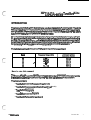
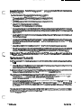
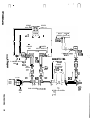
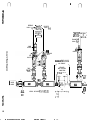
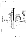
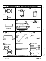
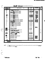
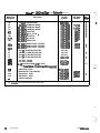
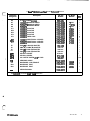
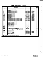
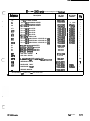
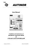
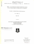
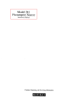
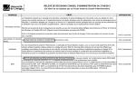
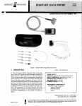
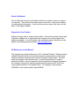
About this Manual
We’ve added this manual to the Agilent website in an effort to help you support
your product. This manual is the best copy we could find; it may be incomplete
or contain dated information. If we find a more recent copy in the future, we will
add it to the Agilent website.
Support for Your Product
Agilent no longer sells or supports this product. Our service centers may be able
to perform calibration if no repair parts are needed, but no other support from
Agilent is available. You will find any other available product information on the
Agilent Test & Measurement website, www.tm.agilent.com.
HP References in this Manual
This manual may contain references to HP or Hewlett-Packard. Please note that
Hewlett-Packard's former test and measurement, semiconductor products and
chemical analysis businesses are now part of Agilent Technologies. We have
made no changes to this manual copy. In other documentation, to reduce
potential confusion, the only change to product numbers and names has been in
the company name prefix: where a product number/name was HP XXXX the
current name/number is now Agilent XXXX. For example, model number
HP8648A is now model number Agilent 8648A.
,. . . _.- .-
INSTALLATION AND SERVICE MANUALm
L
c
I
HP 11643Aseries
TEST SET KITS
l
c
0
C
HEWLETT
PACKARD
Hewlett-pQckzrd Company certifies that this product met its published spec@cations at the time of
shipment from the factory. Hewlett-Packard firther certifies that its calibration measurements are
traceable to the United States National Bureau of Standards, to the extent allowed by the Bureau’s
calibration facility, and to the calibration faciIities of other International Standards Organization
members.
.
WARRANTY
This Hewlett-Packard instrument product is warranted against defects in material and workmanship for a
period of one year from date of delivery. During the warranty period, Hewlett-Packard
Company will, at its option, either repair or replace products which prove to be defective.
For warranty service or repair, this product must be returned to a service facility designated by HP. Buyer
shall prepay shipping charges to HP and HP 8haii pay shipping charges to return the product to Buyer.
However, Buyer shall pay ail shipping charges, duties, and taxes for products returned to HP from another
country.
HP warrants that its software and firmware designated by HP for use with an instrument will execute its
programming instructions when properly installed on that instrument. HP does not warrant that the operation of the instrument, or SOftwafe, or firmware wiii be uninterrupted or error free.
LIMITATION OF WARRANTV
The foregoing warranty shall not apply to defects resulting from improper or inadequate iaintenance by
Buyer, Buyer-supplied software or interfacing, unauthorized modification or misuse, operation outside of
the environmental specifications for the product, or improper site preparation or maintenance.
NO OTHER WARRANTY IS EXPRESSED-OR IMPLIED. HP SPECIFICALLY DISCLAIMS THE IMPLIED
WARRANTIES OF MERCHANTABILITY AND FITNESS FOR A PARTICULAR PURPOSE.
.
EXCLUSIVE REMEDIES
THE REMEDiES.PROViDED HEREIN ARE BUYER’S SOLE AND EXCLUSIVE REMEDIES. HP SHALL NOT
BE LIABLE FOR ANY DIRECT, INDIRECT, SPECIAL, INCIDENTAL, OR CONSEQUENTIAL DAMAGES,
WHETHER BASED ON CONTRACT, TORT, OR ANY OTHER LEGAL THEORY.
ASSISTANCE
Product maintenance agreements and other customer assistance agreements are available for Hewlett-Packard products.
For any assistance, contact your nearest Hewlett-Packard Sales and Service Office. Addresses are provided
at the back of this manual.
c
I
.
HP 11643AISERIES
TEST SET KITS
.
1986
HEWLEIT-PACKARD COMPANY
8 copyright
1400 FOUNTAINGROVE PARKWAY, SANTA ROSA, CA 95403 U.S.A.
MANUAL PART NO. 1164&9O@i5
Mlcroflc~ Part Numbw ll6434OOl6
Print& DECEMBER 1989
HEWLETT
PACKARD
c
, -‘\
/1
HP 11643A-series Test Set Kits
This manual applies to five HP11643A millimeter-wave band test set kits: R, Q, U, V and W. These kits
are assembled to make waveguide reflection/transmission test sets for mm-wave measurements
using the HP 8510 Network Analyzer and other mm-wave components. Refer to the HP 8510 mmwave System manual for complete system level information.
These band dependent kits provide waveguide routing and separation for the reference (a,), reflected
(b,), and transmitted (b2) signals. Each kit also includes three band dependent mixers that allow the
source LO (local oscillator) to mix’with the test signal so that an IF (intermediate frequency) is produced for each of the signals. in addition, each kit contains four band dependent isolators, a fixed load
for terminating the flnai coupler and various components to complete the test set kit.
The table below shows the frequency rang8 and waveguide type of each band:
R
Q
U
V
W
I
26.5 - 40
WR-28
33 - 50
WR-22
WR-19
WR-15
WR-10
40 - 80
50 - 75
75400
How to use this manual
This manual should be used to identify the parts in your kit, order replacement parts, and assemble
the test set for use with a properly configured HP 8510 mm-wave Network Analyzer system.
This manual contains:
l
Test Set Kit Assembly Procedure (for all bands)
l
Test Set Kit Component ld8ntification Sheet (for all bands)
l
Test Set Kit Photographs
l
Test Set Kit Assembly Diagrams
l
Test Set Kit Parts Lists for each band
HP ll643A-series
Test Set Kits
1
Receiving Inspection
inspect the packaging and all parts for damage. Keep all packaging materials for return shipment, if
necessary. If any part is missing or damaged, notify th8 carrier and your nearest Hewlett-Packard
office.
Assembly Procedure
Follow the procedure below to assemble your test set kit on a flat surface before connecting it to the
HP 8510 millimeter-wave system. Use the required screws (see identification sheet), and use the *
waveguide stands supplied in the HP 85100A LO/IF Kit (stands support AT2, DC2, DC3 and AT4) or
supplied with racked systems.
Refer to the Test Set Assembly Diagram and Photograph to properly connect the test set kit.
All of the directional coupler flanges can be easily damaged by improper connections. If you are not
using the HP 11644A waveguide calibration kit straights (with precision flanges) on the test port side of
the couplers, HP 8998 series straights can provide a suitable alternative to avoid damage to the
coupler flanges.
Alignment pins and screws should always be used in a consistent and
R band - Use two alignment pins in opposite corners to align the square shaped flanges. Then
lightly connect them with two screws and nuts. Remove the alignment pins and install th8 other
two screws and nuts. Gradually tighten all four screws in an X pattern.
Q, U, V and W bands - Captive screws are used to make th8 connections.,These partially
threaded screws are designed for repeated use in the tapped round waveguide flanges. Connect
ail four screws lightly. Gradually tighten one screw and then th8 opposite screw to provide even
tOrqU8.
NOTE: Proper connection of waveguide flanges is critical to making good measurements. Be sure
to make the connections as consistent as possible and never ov8rtight8n the connections.
Racked systems (HP 85106A). Refer to the Getting Started section of th8 HP 85106 mm-wave
system manual for instructions about connecting the Test Set kit to the system. The HP 85106A has
portions of the LO/IF section and Test Set kit connections that differ slightly from bench top configurations.
2
Te Set Kits
-J
.
The LO and IF ports of the three harmonic mixers (A7-9) are easily
damaged by electrostatic discharge. Be careful when handling them.
Before Connecting cables to them, short th8 Cab18 outer conductor to
ground. Then short the cable inner conductor to th8 outer conductor.
Finally, short the outer conductor to ground again.
Screws and Alignment Pins.
proper manner as follows:
7
HP ll643A-set-k~
.
c
Assembly Procedure.
properly configured.
Refer to the diagram and the photograph to be sure that the test set kit is
-5-k
1 . Attach isolator AT1 (twist side) to directional coupler DCI.
2. Connect isolator AT2 (twist side) to mixer A7 (use short screws).
.
3. Connect isolator AT3 (twist side) to mixer A8 (use short screws).
.
4. Attach AT2/A7 to difectionai coupler DCl.
Then attach AT3/A8 to directional coupler DC2.
5 . Connect directional coupiers DC1 to DC2: For R, Q and U bands connect the W21 (5cm) straight
section between DC1 and DC2. Note that V and W bands do not use the W21 straight between the
two c0upi0rs.
6 . Use the E2 SMA(m) to SMA(m) adapter to attach one of the A6 power
. divider outputs to th8 LO
input of the A7 mixer.
7 . Looseiy connect one end of the W9 cab18 to the other A6 power divider output. Then loosely
conn8Ct the other end of the W9 cabi8 to the LO input of the A8 mixer. Carefully tighten th8
connections.
8. Attach El and E3 SMA(m) to BNC adapters to the IF outputs of both mixers A7 and A8.
9. Piace the assembled portion of the test set on stands so that it matches the height of the source
,
CL
-r--
module. The soufce module output flange can now be connected to the AT1 isolator input.
10. Attach the AT5 fixed load to th8 directional coupler DC3. If you have an R band kit, also attach the
fiit8t’ FL1 to DC3.
11 . Attach isolator AT4 to mixer A9.
12 Then connect AT4/A9 to the directional coupler DC3, or for R band, to the other side of the filter
FL1 .
l
13. Attach E4 SMA (m) to BNC adapter to the IF port of mixer A9. Then place th8 remaining
assembled section of the test set on stands.
14. If desired, the waveguide twists W22/W23 can be attached to the directional couplers DC2/DC3
for device measurements that require the test ports to be rotated 99 degrees.
15 . At this point, the test set kit is assembled. The HP 11644A calibration kits contain the waveguide
straights (5om). These straights will be attached to th8 directional coupl8rs to provide the port 1
and port 2 measurement planes where devices will be Connected.
16. Connect the test set kit to the LO/IF portion as described in the Getting Started section of th8
appropriate HP mm-wave system manual. For HP 8510A systems, refer to the HP 85129 manual
(HP Part No. 85129-90006). For HP 85108 systems, refer to th8 HP 85106 manual (HP Part No.
85106-90001).
.
TROUBLESHOOTING NOTE: Refer to the HP 8510 mm-wave system manual, Troubleshooting settion, for information about troubleshooting th8 Test Set Kit components in an HP 8510 mm-wave
Network Analyz8f system.
c
HP ll643A-series
TestSBtKitS
3
X
cd
r)
.
n
REFLECTED
REFERENCE
S I G N A L (81)
-
AWPL;VF I
E
L -
-
-
-
R
- A
I AMPLIFIER I lAt,,&l;lE~ I
’
c -
-
-
-
- dL-----.A
TRANSMITTED
SIGNAL (b2)
’
t
I
I
I
I
SEMI-RIGID
CABLE
10 CONNECTED
DIRECTLY BENEATH IF 1
t
I
IIJ
I
I F CO~~~~E~oDIRECTLY
II
f
TOP
VIEW
f
.
I F C O N N E C T E D D I R E C T L Y SMA(m)
TO
BELOW LO
WA(m)
I
TWIST
TOWARDS --
S
w21
-m--w
I
TWIST
TOWARDS
DC1
WAVEt3lJIDE T W I S T S C A N BE
CONNECTED BETWEEN COUPLER
AND STRAIOHT
0
STANDS: USE UNDER AT2,AT4,DC2,DC3.
I
TOP
VIEW
!2
AT4
STRAIGHTS
WITH PRECISION
FLANGE FROM
HP11644A CAL Kl
/
PORT 1
PORT
FL1
8[
I
.AI
DC3
f IXEO
LOAD
.
Q and U Band Test Set Kit
6-
Ta Set Kits
1,
-i.
-_
r)
REFERENCE
; - <Pii ii iA- ;
S I G N A L (1
-), (OPT.001) ,a
,AMPLlFIER
---a--J
c
REFLECTED
S I G N A L (bl)
; HPii915A-;
-m-B--
LO
IL A M P L I F I E R 1
;
HP8447A
I
' rI -i@-l-ifi:A-;
I MWLIFlE* I IAMpLLl~lE~
L - - - - - - J L - - - - - -
-m----J
TRANSMITTED
S I G N A L ib2)
POWER
DIVIDER
BNC
ADAPTER
WB
SEMI-RIGID
CABLE
BNC
ADAPTER 1
WAVEGUIDE T W I S T S C A N B E
CONNECTED BETWEEN COUPLER
AND STRAIGHT
\
STRAIGHTS
WITH PRECISION
FLANGE FROM
HP11644A CAL KIT
ml
ml
TWIST
TOWARk - l\r
MIXER
/
c-----l
I
I
fl
SOURCE
MODULE
- .“. .- _..--._--- _____ --- -.-.--._-
_
.
STANDS: USE UNDER AT2,AT4,DC2,DC3.
.
- - - - -_--. . .
-_ -_ _ _ _. _ ^-__ I _-
B
c---3
'
PORT
fL'
'
R-BAND
t ’ 7 -ONLY
1
fl
;
- - *II
Ilk - - 441 I
11
LJ I
L
Itr
TWiST
TOWARDS
DC1
_
1
\
AT4
-
-
-
S21
-
J
-
AT5
F I XED
LOAD
I
J
V and W Band Test Set Kit
8
TestsetKitS
HP Il643A-saies
.
(1
RfFLEcTfD
SIWUbl)
TRRNSMITTfD
SIGML (b2)
II
BNC fUHf’TE:R
94?(m) t o
StUMm) A
R7
MGUIDf TWISTS CR4 Bc: CCNECTED
BETHEW COUPLEIf? FM] STWIGKV
1
~STRRICHTS WITH Pf?ECISIoN FLCNCT
fRCM t-P 11644R CRL K I T
PORT1
I
;
SOURCE
I
I’IODULE
I
L-
-J
TWIST
T?zTE
S t a n d s : U s e u n d e r fiT2, F)T4, DC2, D C 3 .
FORT2
r------1
I
e
LO
R9
HP 11643A-SERIES TEST SET KIT COMPONENT IDENTIFICATION SHEET
AT+4 Isolators (4)
A6 Power Divider (1)
A7-9 Mixers (3)
SMA (F)
SMA (F)
AT5 Fixed Load (1)
SMA (F)
DCl-3 Directional Couplers (3)
FL1 Low Pass Filter (1)
Adapters
El, 394 (3)
SMA (M) e BNC (F)
~~
SMA(M)
6
1
SMA(M)
Q, U, V, W Band Type
R Band: W9
Semi-Rigid Cable (1)
SMA (M)
Q and V Band: W9
Semi-Rigid Cable (1)
V and W Band: W9
Semi-Rigid Cable (1)
SMA (M)
MPG2 Hex Ball Driver (2)
R, Q, U Bands:
W21 Waveguide Straight (1)
4-40 Screws - Nuts (100 ea.)
R Band:
MP3 (.375 in)
(5 cm long)
MP4 (500 in)
HI
W22-23 Waveguide Twists (2)
90
0
Q, U, V, and W Bands:
(No Nuts Required)
NUT - MP5
(Use With MP4)
MP6 (.312 in)
.
10
NOTE: Semi-rigid cables may require some bending to make a proper fit. Avoid kinks.
Test Set Kits
HP ll643Aeeries
R Bad - HP 11643A-series Test Set Kit Replaceable Parts List
c
HP Part
Number
HP Model
Number
-a
2-8 GHz POWER DIVIDER
26.540 GHz HARMONIC MIXER
26.5-40 GHz HARMONIC MIXER
26.5-40 GHz HARMONIC MIXER
0955-0264
11643-60027
11643-60027
11643-60027
*I 1970A
+I 1970A
*11970A
1
1
1
1
26.5-40 GHz
26.5-40 GHz
26.5-40 GHz
26.5-40 GHz
26.5-40 GHz
ISOLATOR
ISOLATOR
ISOLATOR
ISOLATOR
FIXED LOAD
11643-60002
11643-60002
11643-60002
11643-60002
11643-60013
R365A
R365A
R365A
R365A
RQI OA
1
1
1
1
1
DC1
DC2
DC3
26.5-40 GHr DIRECTIONAL COUPLER
26.5-40 GHr DIRECTIONAL COUPLER
26.5-40 GHz DIRECTIONAL COUPLER
11643-60005
11643-60005
11643-60005
R752D
R7520
R752D
1
1
1
El
E2
E3
E4
BNC (F) TO SMA (M) ADAPTER
SMA (M) TO SMA (M) ADAPTER
BNC (F) TO SMA (M) ADAPTER
BNC (F) TO SMA (M) ADAPTER
FL1
LOW PASS FILTER
hfwence
hsignator
A6
A7
A8
A9
l
l
AT1
Al2
AT3
AT4
AT5
\.
c
MPl
mm
NIP3
’
*
MP4
MP5
w9
w21
l W22
W23
Description
I
1250-1200
1250-1159
1250-1200
1250-1200
11643-60001
HEX BALL DRIVER
HEX BALL DRIVER’
4-40 SKT HO SCRE\;V .375 IN LONG
(SEE NOTE BELOW)
440 SKT HO SCREW .500 IN LONG
440 HEX NUT .062 IN. THICK
(USE WITH MP4)
SEMI-RIGID CABLE
WAVEGUIDE 5 CM STRAIGHT
WAVEGUIDE TWIST
WAVEGUIDE TWIST
-
R362A
1
8710-1539
8710-1539
3030-0221
1
1
100
3030-0209
2260-0002
100
100
85100-20006
11643-60016
11643-60008
11643-60008
SERVICE MANUAL
1
1
1
1
R899B
R898A
R898A
11643-90015
1
1
1
1
1
.
l
NOTE:
Not replaceabJe by part number. Order HP model number listed.
MP3 - Use this screw to connect Isolator AT1 to the source module and to connect Isolators AT2-4 to
the flanges of mixers A7-9.
HP ll643A-mies
Test Set K~~YB
11
Q Bad - HP 11643Aeeriw Td Set Kit Replaceable Parts List
Reference
Designator
Description
HP Part
Number
HP Model
Number
095500264
11643-60028
'11970Q
QW 0
A8
A7
A8
A9
2-8 GHz POWER DIVIDER
33-50 GHz HARMONIC MIXER
33-50 GHz HARMONIC MIXER
33-50 GHz HARMONIC MIXER
11643-60028
l 11970Q
11643-60028
'11970Q
AT1
AT2
AT3
AT4
AT5
33-50
33-50
33-50
33-50
33-50
11643-60003
11643-60003
116e6ooo3
11w
11643-60014
Q365A
Q365A
Q365A
Q365A
QQI OA
1
1
1
DC1
33-50 GHz DIRECTIONAL COUPLER
33-50 GHz DIRECTIONAL COUPLER
33-50 GHz DIRECTIONAL COUPLER
11-6
11643-6ooo6
11643-60006
Q752D
Q7520
Q7520
1
GHz ISOLATOR
GHz ISOLATOR GHz ISOLATOR
GHz ISOLATOR
GHr FIXED LOAD
1
1
1
1
1
1
1
1
El
E2
E3
E4
BNC (F) TO SMA (M) ADAPTER
SMA (M) TO SMA (M) ADAPTER
BNC (F) TO SMA (M) ADAPTER
BNC (F) TO SMA (M) ADAPTER
1250-1200
1250-1159
1250-1200
1250-1200
1
MPl
MP2
MP6
HEX BALL DRIVER
HEX BALL DRIVER
4-40 CAPTIVE SCREW .312 IN LONG
(Use for all test S8tamWCtionS - no nut required)
8710-1539
8710-1539
13906671
1
w9
w21
W22
W23
SEMI-RIGID CABLE
WAVEGUIDE 5 CM STRAIGHT
WAVEGUIDE TWIST
WAVEGUIDE TWIST
85100-20007
11643-60011
11643-60009
11643-60009
-
SERVICE MANUAL
11643-90015
1
1
1
1
100
Q899B
Q898A
Q898A
1
1
1
1
1
Not replace&b by part number. Order HP model number listed.
l
13
Test Set Kits
.
HP Il643Aeeries
1-
C
l
.
‘\
C
U Band - HP 11643A-aedw T& Set Kit Repiaceabie Parts List
Reference
Designator
Description
HP Part
Number
HP Model
Number
Qw a
A6
A7
A8
A9
2-8 GHz POWER DliilDER
40-60 GHz HARMONIC MIXER
40-60 GHz HARMONIC MIXER
40-60 GHz HARMONIC MIXER
095500264
11643-60029
11643-60029
11643-60029
*I1970U
*I 197ou
*I1970U
1
AT1
AT2
AT3
AT4
AT5
40-60
40-60
40-60
40-60
40-60
11643-60004
11643-60004
11643-60004
.l1643-60004
11643-60015 ,
U365A
U365A
U365A
U365A
US1 OA
1
1
1
1
,I
DC1
DC3
40-60 GHz DIRECTIONAL COUPLER
40-60 GHr DIRECTIONAL COUPLER
40-60 GHz DIRECTIONAL COUPLER
11643-60007
11643aoo7
11643-60007
U752D
U752D
U752D
1
1
1
El
E2
E3
E4
BNC (F) TO SMA (M) ADAPTER
SMA (M) TO SMA (M) ADAPTER
BNC (F) TO SMA (M) ADAPTER
BNC (F) TO SMA (M) ADAPTER
1250-1200
1250-1159
1250-1200
1250-1200
MPl
MP2
MP6
HEX BALL DRIVER
HEX BALL DRIVER
440 CAPTIVE SCREW .312 IN LONG
8710-1539
8710-1539
13QO-0671
w9
w21
W22
SEMI-RIGID CABLE
WAVEGUIDE 5 CM STRAIGHT
WAVEGUIDE TWIST
85100-20007
11643-60012
11643-60010
U899B
U898A
1
1
1
W23
WAVEGUIDE TWIST
11643-60010
U898A
1
-
SERVICE MANUAL
11643-90015
l
GHz
GHz
GHz
GHz
GHr
ISOLATOR
ISOLATOR
ISOLATOR
ISOLATOR
FIXED LOAD
1
1
1
1
1
1
1
1
1
100
1
Not replaceable by part number. Order HP model number listed.
.
-\
c
Test Set Kits
13
V Batrrd - HP 11643A-seriw Td Set Kit Reptoceabie Parts List
Reference
Designator
Description
HP Model
Number
Qw a
A6
A7
A8
A9
2-8 GHz POWER DIVIDER
50-75 GHz HARMONIC MIXER
50-75 GHz HARMONIC MIXER
50-75 GHz HARMONIC MIXER
0955-0264
1164340030
11643-60030
11643-60030
l11970v
*11970v
*I1970v
1
1
1
1
AT1
An
AT3
AT4
AT5
50-75
50-75
50-75
50-75
SO-75
1164340017
1164340017
11643-60017
1164340017
1164340025
V365A
V365A
V365A
V365A
VQI 0A
1
1
1
1
1
DC1
DC2
DC3
50-75 GHz DIRECTIONAL COUPLER (20 dB)
50-75 GHz DIRECTIONAL COUPLER (20 dB)
50-75 GHz DIRECTIONAL COUPLER (20 dB)
11643-60021
11643-6iIO21
11643-60021
V752D
V752D
V752D
1
1
1
El
E2
E3
E4
BNC(F) TO SMA(M) ADAPTER
SMA(M) TO SMA(M) ADAPTER
BNC(F) TO SMA(M) ADAPTER
BNC(F) TO SMA(M) ADAPTER
1250-1200
1250-1159
1250-1200
1250-1200
1
1
1
1
MPl
MP2
HEX BALL DRIVER
HEX BALL DRIVER
8710-1539
871 1539
1
1
MP6
4-40 CAPTIVE SCREW .312 IN LONG
(Use for all test connections - no nut required)
1390-0671
100
w9
SEMI-RIGID CABLE
85100-20010
W22
W23
WAVEGUIDE TWIST
WAVEGUIDE TWIST
L4
SERVICE MANUAL
11643-60023
11643-60023
m-m
GHz
GHz
GHz
GHz
GHz
ISOLATOR
ISOLATOR
ISOLATOR
ISOLATOR
FIXED LOAD
+ Not replaceable by part ntimbew. Order HP model number listed.
14
HP Part
Number
Test Set Kits
11643-90015
1
V898A
V898A
1
1
1
W Band - HP 11643A-tiei Test Set Kit Replaceable Pm L&t
Refefence
Designator
.
Description
A6
A7
A8
A9
2-8 GHz POWER DIVIDER
75-l 10 GHz HARMONIC MIXER
75-l 10 GHz HARMONIC MIXER
75-110 GHz HARMONIC MIXER
AT1
AT%
AT3
iIT4
AT5
75-l 10 GHz
75-l 10 GHz
75-l 10 GHz
75-l 10 GHz
75-110 GHz
DC1
DC2
75-l 10 GHz DIRECTIONAL COUPLER (20 dB)
75-l 10 GHz DIRECTIONAL COUPLER (20 dB)
75-l 10 GHz DIRECTIONAL COUPLER (10 dB)
El
E2
E3
E4
BNC(F) TO SMA(M) ADAPTER
SMA(M) TO SMA(M) ADAPTER
BNC(F) TO SMA(M) ADAPTER
BNC(F) TO SMA(M) ADAPTER
MPl
MP2
HEX BALL DRIVER
HEX BALL DRIVER
NIP6
440
CiPTIVE
SCREW
.312 IN-LONG
(Use
for all test
connections
no nut required)
w9
ISOLATOR
ISOLATOR
ISOLATOR
ISOLATOR
FIXED LOAD
HP Part
Number
HP Model
Number
Qw 8
1
0955-0264
11643-60031
11643-60031
11643-60031
l 11970w
1
*I1970W
+I 197ow
1
1
11643-60018
11643-60026
W365A ’
W365A
W365A
W365A
w910c
1
1
1
1.
1
11643-60022
11643-60022
11643-60020
W752D
W752D
W752C
1
1
1
11643-60018
11643-60018
116434W10
’
,125~1200
1250-1159
1250-1200
1250-1200
1
1
1
1
8710-1539
8710-1539
1
1390-0671
100
SEMI-RIGID CABLE
85100-20011
1
W22’
W23
WAVEGUIDE TWIST
WAVEGUIDE TWIST
11643-60024
11643-60024
woo
SERVICE MANUAL
11643-90015
l
-
Not replaceable by m number. Order HP model number listed.
1
W898A
W898A
1
1
1
.
Test Set Kits
15116
.
REGIONAL SALES AND SUPPORT OFFICES
C
c1
.
For information relating to Sales or Support of Hewlett-Packard products first contact your local Hewlett-Packard
oflce &ted in the whit8 pages of your telephone directory. /f non8 is listed loca//y, contact on8 of the addresses
listed b8/ow to obtain th8 address or phone number of the HBwiett-Packard Sales of Support oike nearest you.
ASIA
BENELUX & SCANDINAVIA
UNITED KINGDOM
Hewlett-Packard Asia Ltd.
47/F, 26 Ha&our Road,
Wanchal, HONG KONG
G.P.O. Box 863, Hong Kong
Tel: (652) 5-6330633
Telex: 76793 HPA HX
Cable: HPASIAL TO
Hewlett-Packard S.A.
Uil8fWt8d8 475
P.O. Box 999
NL-1163 AG AMSTELVEEN
Th8 Netherlands
Tel: (31) 20143 77 71
Telex: 18 919 hpner nl
Hewlett-Packard Ltd.
King Street Lane
Winnersh, WOKINGHAM
Berkshire RGII 5AR
Tel: 734/78 47 74
Telex: 847178
AUSTRALASIA
SOUTH & EASTEUROPE,
AFRICA
Hewlett-Packard Australia Ltd.
31-41 Joseph stf88t
BLACKBURN, Victoria 3130
Australia
Tel: (61) 895-2895
Telex: 31-024
Cable: HEWPARD M8lboufne
Hewlett-Packard S.A.
7, rue du Boisdu-Lan
CH-1217 MEYRlN 2, Geneva
Switzerland
Tel: (41) 22/63 12 12
Telex: 27635 hmea
Cable: HEWPACKSA Geneve
CANADA
c
H8wl8tt-Packard (Canada) Ltd.
6877 Goreway Drive
MISSISSAUGA, Ontario L4V lM8
Tel: (416) 676-9430
Telex: 069-8644
JAPAN
Yokogawa-Hewlett-Packard Ltd.
29-21 Takaido-Higashl, 3 Chom8
Suginami-ku TOKYO 168
Tel: 03 (331) 6111
Telex: 232-2024 YHPTOK
MEDITERRANEAN AND
MIDDLE EAST
l
*
c
Hewlett-Packard S.A.
Mediterranean and Middle East
Operations
Atrina Centre
32 Kifissias Avenue
Paradissos-Amarousion, ATHENS
Greece
Tel: (30) 662 88 11
Telex: 21-6588 HPAT GR
Cable: HEWPACKSA Athens
February, 1986
FRANCE
Hewlett-Packard Franc8
Part d’activites du Bois Briard
. 2, avenue du Lac
91040 EVRY Cedex
Tel: 1 61077 63 63
Telex: 6923 15F
GERMAN FEDERAL
REPUBLIC
Hewlett-Packard GmbH
Hewlett-Packard-Strasse
Postfach 1641
D-6380 BAD HOMBURG
West Germany
Tel: 06172/400-O
Telex: 410 844 hpbhg
ITALY
Hewlett-Packard italiana S.p.A.
Via G. Di Vittorio 9
I-20063 CERNUSCO SUL
NAVIGLIO
(Miiano)
Tel: 02/92 36 91
Telex: 334632
EASTERNUSA
Hewlett-Packard Co.
4 Choke cherry Road
ROCKVILLE, MD 20850
Tel: (301) 670-4300
MIDWESTERN USA
Hewlett-Packard Co.
5201 Toiiview Drive
ROLLJNG MEADOWS, IL 60008
Tel: (312) 255-9800
SOUTHERN USA
Hewlett-Packard Co.
2000 South Park Place
P.O. Box 105005
ATLANTA, GA 30348
Tel: (404) 955-1500
I
WESTERN USA
Hewlett-Packard Co.
5161 Lankershim Blvd.
P.O. Box 3919
NO. HOLLYWOOD, CA 91609
Tel: (818) 506-3700
OTHER INTERNATIONAL
AREAS
Hewlett-Packard Co.
intercontinental Headquarters
3495 D8ef Creek Road
PALO ALTO, CA 94304
Tel: (415) 857-1501
Telex: 034-6300
Cable: HEWPACK
I
c
HEWLETT
PACKARD
-\.
-’i
Printed in U.S.A.
I
,
I