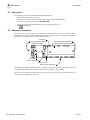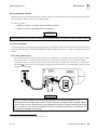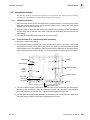
1
TCO M ® 2 Transcutaneous CO2/O2 Monitor Service Manual Model 860 May 16, 1997 Catalog No. 6590-90-00 Novametrix Medical Systems Inc. 5 Technology Drive Wallingford, Connecticut, U.S.A. 06492. Copyright 1997. All rights reserved. No part of this manual may be reproduced without the written permission of Novametrix Medical Systems Inc. Printed in U.S.A. R Revision History 16-May-97 Release at revision 00. This document contains information which is proprietary of Novametrix Medical Systems, Inc., and may not be reproduced, stored in a retrieval system, translated, transcribed or transmitted, in any form, or by any means, without the prior explicit written permission of Novametrix Medical Systems Inc. Novametrix reserves the right to change specifications without notice. TCO2M and NOVADISK are registered trademarks, and NovaCARD and NovaCOM are trademarks of Novametrix Medical Systems Inc. Rev. 00 Model 860 Service Manual iii [This page intentionally blank.] iv Model 860 Service Manual Rev. 00 G Guarantee Equipment manufactured or distributed by Novametrix Medical Systems Inc., is fully guaranteed, covering materials and workmanship, for a period of one year from the date of shipment, except for certain disposable products and products with stated guarantees other than one year. Novametrix reserves the right to perform guarantee service(s) at its factory, at an authorized repair station, or at the customer’s installation. Novametrix’ obligations under this guarantee are limited to repairs, or at Novametrix’ option, replacement of any defective parts of our equipment, except fuses, batteries, and calibration gasses, without charge, if said defects occur during normal service. Claims for damages during shipment must be filed promptly with the transportation company. All correspondence concerning the equipment must specify both the model name and number, and the serial number as it appears on the equipment. Improper use, mishandling, tampering with, or operation of the equipment without following specific operating instructions will void this guarantee and release Novametrix from any further guarantee obligations. Service Department For factory repair service, call toll free 1-800-243-3444 In Connecticut, call Collect (203) 265-7701 FAX (203) 284-0753 http://www.novametrix.com Email [email protected] Caution: Federal (U.S.A.) law restricts this device to sale, distribution, or use by or on the order of a licensed medical practitioner. Copyright 1997, Novametrix Medical Systems Inc. This document contains information which is proprietary and the property of Novametrix Medical Systems Inc., and may not be reproduced, stored in a retrieval system, translated, transcribed, or transmitted, in any form, or by any means, without prior explicit written permission from Novametrix Medical Systems Inc. Rev. 00 Model 860 Service Manual v Service Policy Novametrix Medical Systems Inc. will provide Warranty Service Support to its customers within 48 hours of receiving a telephone request for technical support. This 48 hour period begins once a service request is placed through the Factory Technical Support Department in Wallingford, Connecticut. Novametrix provides factory direct technical support to its customers through a technical support group located in Wallingford, Connecticut and company service representatives located throughout the United States. All Technical Support for Novametrix products is provided “Factory Direct”. Novametrix provides 24 hour a day technical support accessibility via telephone numbers (800) 243-3444 or (203) 265-7701. After hours technical support requests (before 8:00 AM and after 5:00 PM Eastern Time) will be responded to promptly by the Technical Support On-Call staff. It is suggested that any person calling in for technical support have the inoperative equipment available for preliminary troubleshooting as well as product identification. Novametrix reserves the right to repair or replace any product found to be defective during the warranty period. Repair may be provided in the form of replacement exchange parts or accessories, on-site technical repair assistance or complete system exchanges. Repairs provided due to product abuse or misuse will be considered “non-warranty” and invoiced at the prevailing service rate. Any replaced defective material is expected to be returned to Novametrix within 10 days of being provided in order to avoid additional charges. Exchanged material should be returned promptly and directly to Novametrix using the return paperwork and shipping label(s) provided. Transferring return materials to local sales or dealer representatives does not absolve return responsibility. Novametrix manufactures equipment that is generally “user serviceable” and can usually be repaired with the replacement of a plug-in electro-mechanical assembly by the clinical end user. When repair parts are provided, the recipient can call into Novametrix for on-line replacement assistance and repair assurance. In the event a replacement part requires increased technical capability, Technical Support may request Biomedical assistance, provide on-site technical support or complete replacement equipment. If the customer requires the return of their original product, the exchange material will be considered “loaner material” and exchanged again after the customer equipment is repaired. Novametrix promotes customer participation in warranty repairs should they become necessary. This program allows for customer training and a smooth transition into self-maintenance after warranty, which can provide substantial cost savings on repairs throughout the product’s life. The Novametrix Technical Support Department can provide technical product support at a level appropriate to most customers protocol and budget requirements. Please contact the Technical Support Group at Novametrix for additional information. Additional Novametrix Technical Support Programs • Focus Series Technical Training Seminars • Test Equipment and Test Kits • Service Contract / Part Insurance Plans • On-Site Technical Support • 24 hr. telephone support • “Demand Services” Flat rate parts-exchange, Flat rate return for repair Time and Material, Full warranty, discounted replacement sensors vi Model 860 Service Manual Rev. 00 C Contents Section1 Safety ............................................................................................................. 1 Patient Safety .............................................................................................................. 1 Contraindications ........................................................................................................ 1 Section2 Description .................................................................................................... 3 Conventions ................................................................................................................ 4 Summary of Operation ................................................................................................ 4 Front and Rear Illustrations ......................................................................................... 5 Symbols ...................................................................................................................... 6 Section3 Theory of Operation ..................................................................................... 7 2726 Power Supply Board .......................................................................................... 7 AC Mains and Battery Operation Overview ..................................................................... 7 AC Operation ................................................................................................................... 7 2533 CPU Interface Board .......................................................................................... 8 Power On/Off Control Circuitry ........................................................................................ 8 Power Supplies ............................................................................................................... 9 Precision Reference Supplies ......................................................................................... 9 Low Battery Voltage Shutdown ....................................................................................... 9 Microprocessor .............................................................................................................. 10 Memory ......................................................................................................................... 10 Real Time Clock (RTC) ................................................................................................. 10 Sound generator ............................................................................................................ 11 Keypanel Interface ........................................................................................................ 11 Display Interface ............................................................................................................ 11 I/O Device Controller ..................................................................................................... 12 Watchdog Timer ............................................................................................................ 12 RS232 Serial Communication ....................................................................................... 12 Calibrator Control .......................................................................................................... 13 Barometric Pressure ...................................................................................................... 13 Analog to Digital Conversion ......................................................................................... 13 Temperature Control ..................................................................................................... 14 Battery Voltage Monitoring ............................................................................................ 14 2534 Front End Board ...............................................................................................14 Sensor Temperature Monitoring .................................................................................... 14 Sensor Heater Control ................................................................................................... 14 Software Heater Shutdown Control ............................................................................... 15 Sensor Temperature Fault Monitoring ........................................................................... 15 Sensor Heater Power- Local Power .............................................................................. 16 Sensor Identification ...................................................................................................... 16 Sensor Oxygen Value Measurement ............................................................................ 17 Sensor Carbon Dioxide Value Measurement ................................................................ 17 Multiplexor ..................................................................................................................... 17 Rev. 00 Model 860 Service Manual vii Section4 Maintenance ................................................................................................ 19 Cleaning and Disinfecting ......................................................................................... 19 Monitor/Calibrator .......................................................................................................... 19 Sensors ......................................................................................................................... 19 Calibrator ....................................................................................................................... 19 TCO2M Calibrator, Model 868 .................................................................................. 20 Setting up the Calibrator ............................................................................................... 20 Disconnecting Gas Cylinders ........................................................................................ 21 Connect the calibrator ................................................................................................... 21 Battery Maintenance ................................................................................................. 21 Fuses ........................................................................................................................ 22 Changing AC Mains Voltage ..................................................................................... 23 Assembly Exchanges ................................................................................................ 25 Internal Assemblies ....................................................................................................... 25 Front End and CPU - Interface/Keypanel Assembly ..................................................... 25 Replacing the internal battery ....................................................................................... 26 Changing System Software ...................................................................................... 26 Barometric Pressure ................................................................................................. 27 Section5 Troubleshooting ......................................................................................... 29 General ..................................................................................................................... 29 Display Messages ..................................................................................................... 30 Section6 Functional Tests ......................................................................................... 33 Equipment Required ................................................................................................. 33 System Tests ............................................................................................................ 33 Section7 Electronic Tests .......................................................................................... 35 2726-01 Power Supply Board Tests ......................................................................... 35 Equipment Required ..................................................................................................... 35 Tests ............................................................................................................................. 35 2533-01 CPU - Interface Board Tests ....................................................................... 36 Equipment Required ..................................................................................................... 36 Tests ............................................................................................................................. 36 2534-01 Front End Board Tests ................................................................................ 38 Equipment Required ..................................................................................................... 38 Tests ............................................................................................................................. 38 Safety Tests .............................................................................................................. 41 Section8 Specifications ............................................................................................. 43 Monitor Model 860 .................................................................................................... 43 Sensors ..................................................................................................................... 44 Gas Calibrator Model 868 ......................................................................................... 44 Section9 Accessories ................................................................................................ 45 Section10 Parts ............................................................................................................. 47 Model 860 ................................................................................................................. 47 Model 868 Calibrator ................................................................................................. 54 Newer Calibrator ........................................................................................................... 54 Older Calibrator ............................................................................................................. 55 viii Model 860 Service Manual Rev. 00 1 Safety 1.1 Patient Safety • The location of the sensor on the patient should be changed periodically to minimize the risk of burns due to heating of the skin by the sensor. The risk of such a burn is dependent upon the sensor temperature, duration of application and physiological parameters including local perfusion, body temperature, and skin thickness. • TCO2M monitor has electrically isolated inputs. Patient leakage current flowing from the instrument to ground is limited to less than 10 µA at 120 V, 60 Hz. Patient isolation is greater than 10 MΩ, 2500 V rms at 60 Hz. For maximum patient and operator safety, the following procedures are recommended; • Keep the TCO2M and its accessories clean. • Do not operate the TCO2M when it is wet due to spills or condensation. • Do not touch the patient while making adjustments on the TCO2M monitor. • Whenever possible, the TCO2M monitor should be connected to the same circuit as other equipment in use on the same patient. Outlets that are on the same circuit can be identified by your hospital’s engineering department. • In areas where electromagnetic devices (i.e., electrocautery) are used, patient monitoring may be interrupted due to electromagnetic interference. • The PtcCO2 display reading (CO2) is factory set to reflect the metabolic factor for pCO2 and the value is corrected only during patient monitoring—not during calibration. Refer to the User’s Manual for more information. • Components of this product and its accessories which have patient contact are latex free. • Connect only Novametrix supplied transcutaneous sensors and gas calibrators to the TCO2M Model 860 monitor front panel input connectors. Refer to “Accessories” on page 45 for listings and catalog numbers. 1.2 Contraindications • In patients who are hemodynamically compromised, transcutaneous gas values may no longer reflect arterial gas values due to changes in blood flow to the tissue. • Patients with extremely sensitive skin should be carefully evaluated prior to monitoring as sensor heat or adhesive ring application may cause skin irritation. Skin irritation due to the adhesive ring can be minimized by loosening the adhesive with alcohol or water prior to its removal from the patient. • HALOTHANE INTERFERENCE. Halothane is the only known anesthetic gas affecting the reliability of transcutaneous oxygen (PtcO2) measurement as demonstrated in in-vitro testing of the Transcutaneous Combination O2/CO2 Sensor (PN:4474). The affect of halothane on transcutaneous oxygen measurements in-vivo has not been determined. Halothane does not affect the transcutaneous carbon dioxide (PtcCO2) measurement of the Transcutaneous Combination O2/CO2 Sensor. No known anesthetic gasses affect the performance of the Transcutaneous Oxygen Sensor (PN:6754) or the Transcutaneous Carbon Dioxide Sensor (PN:6752). Rev. 00 Model 860 Service Manual 1 1 Safety Contraindications • PtcO2 levels in excess of 150 mmHg may cause drift of PtcCO2 portion of the 4474-00 Combination O2/CO2 Sensor using an 8900 Split Membrane NOVADISK. This drift is not experienced with the 4474-39 Combination O2/CO2 Sensor and 8575 NOVADISK, nor with the Transcutaneous Oxygen Sensor (PN:6754) or the Transcutaneous Carbon Dioxide Sensor (PN:6752). WARNING Indicates a potentially harmful condition that can lead to personal injury. • Explosion Hazard: Do NOT use the TCO2M in the presence of flammable anesthetics. Use of this instrument in such an environment may present an explosion hazard. • Electrical Shock Hazard: Always turn the monitor off before cleaning it. Do NOT use a damaged sensor or one with exposed electrical contacts. • Failure of Operation: If the monitor fails to respond as described, do not use it until the situation has been corrected by qualified personnel. • Fire Hazard: The TCO2M and its sensors should not be exposed to elevated oxygen levels at elevated pressures. Use of this instrument in such an environment may present a fire hazard. • For installation where the integrity of the external protective earth conductor arrangement is in doubt, the equipment should be operated from its internal battery only. • No user serviceable parts inside. Refer servicing to qualified service personnel. CAUTION Indicates a condition that may lead to equipment damage or malfunction. • Federal (U.S.A.) law restricts this device to sale, distribution, or use by or on the order of a licensed medical practitioner. • No tension should be applied to the sensor cable. • Avoid storing the monitor and sensors at temperatures less than -10° C or greater than +55° C (<14° F or >131° F). • Do NOT immerse the monitor or sensors in liquids. • Do NOT sterilize the monitor or the sensors. • Electric Shock Hazard. Do NOT remove covers or panels. Refer servicing to qualified service personnel. • Connect the line cord only to a grounded hospital-grade outlet. • For continued protection against fire hazard, replace fuses only with those of the same type and rating. • No user serviceable parts inside. Refer servicing to qualified service personnel. • Operate at temperature between +10° C to +40° C (50-104° F), < 90% relative humidity (noncondensing). 2 Model 860 Service Manual Rev. 00 2 Description This manual is written for users of the Novametrix TCO2M Transcutaneous monitor, Model 860. The TCO2M is a dual parameter, noninvasive transcutaneous gas monitor. It provides reliable, continuous measurement, displays and alerts for transcutaneous oxygen tension (PtcO2), transcutaneous carbon dioxide tension (PtcCO2) and sensor temperature. Transcutaneous oxygen is measured with an oxygen sensor consisting of two parts; 1) a modified Clarktype polarographic sensor, a silver anode, electrolyte and an oxygen permeable membrane, and 2) a heating section with two precision thermistors for measuring and controlling the sensor temperature. When the sensor is subjected to oxygen, the oxygen molecules diffuse through the membrane and create an electro-chemical reaction which causes current to flow through the cathode. An amplifier connected to the cathode measures the amount of current flowing and converts it to a value proportional to the oxygen tension at the sensor/membrane interface. This information is displayed as PtcO2. Transcutaneous carbon dioxide is measured with a sensor that utilizes a unique pH sensor based on the Stow-Severinghaus principle. The carbon dioxide sensor is composed of two parts; 1) a carbon dioxide sensor consisting of a pH sensor, reference sensor, electrolyte and a carbon dioxide permeable membrane, and 2) a heating section with two precision thermistors for measuring and controlling the sensor temperature. When the sensor is subjected to carbon dioxide, the carbon dioxide molecules diffuse through the membrane and react with the electrolyte. This reaction alters the pH of the electrolyte solution, which in turn changes the voltage across the pH and reference sensors. Since carbon dioxide is the only gas that can affect the pH of the electrolyte, there is a direct correlation between pH and the amount of CO2 present. This relationship is expressed by the Henderson-Hasselbach equation: pH = pKa + log HCO3 0.03 pCO2 An amplifier measures this voltage change and converts it to a value corresponding to the carbon dioxide tension at the sensor/membrane interface. This information is displayed as PtcCO2. The following sensors may be used with the TCO2M: Rev. 00 Cat. No. Sensor Type 4474-00 Combination O2/CO2 Sensor 4474-39 Combination O2/CO2 Sensor 6752 Carbon Dioxide Sensor 6754 Oxygen Sensor Model 860 Service Manual 3 2 Description Conventions 2.1 Conventions The following conventions will be used throughout this manual: • • • • Normal text will be shown in this type. Message center displays, menu titles and displays will be shown IN THIS TYPE. The names of soft keys will be shown IN THIS TYPE. The image of front panel keys (hard keys) will be displayed as their icon, e.g. - POWER key. 2.2 Summary of Operation The front panel of the TCO 2 M contains hard keys (dedicated front panel keys), soft keys (menu dependent keys) and icon symbols (illuminating indicators). When the monitor is powered up and passes its self-test, it will display a screen similar to the one below: CO2 Factor PtcCO2 Parameter Information (upper/lower limits) Real Time Waveform Display Trend Parameter & Display Time Alert Limits Sensor Temperature Battery Icon Menu (soft key identifiers) The display is arranged in different sections; parameter information for PtcCO2 and PtcO2, real time waveform display and the menu display. A full screen trend display is also available. The first menu to appear in normal operation is the main menu, from here all other sub-menus are accessed by pressing particular soft keys. 4 Model 860 Service Manual Rev. 00 Description Front and Rear Illustrations 2 2.3 Front and Rear Illustrations Display Red Alert Bar TCO2M Calibrator, Model 868 connection Sensor input Power button - Press to turn the monitor on/off. Audio disable icon - Flashes yellow when the audio has been disabled. -used on some models. Rev. 00 “LOW BAT” - Red when battery is near depletion. (A similiar icon appears in the display when the monitor is running on battery power and gives a visual indication of the charge left on the battery.) Alert Reset key - Press to acknowledge and reset alerts. AC indicator - Green when the monitor is connected to AC power and the rear panel power entry module switch is set to “|” (ON). Also indicates the battery is charging. Alert indicator - Flashes red to indicate an alert condition. Two minute silence indicator Illuminates yellow when the audio has been temporarily silenced using the two minute silence feature. Contrast key - Press and hold to vary the contrast of the display. Audio key - Press to toggle two minute silence. Press and hold for audio disable. Soft key - Five keys that function according to the command shown above each key in the display. Event key - Press to mark an event in trend memory. Model 860 Service Manual 5 2 Description Symbols 1 2 4 5 3 6 1 Ground stud. Use to connect monitor’s chassis to earth ground. 2 Indicates fuse rating information for mains fuse. 3 RS232 port for Novametrix accessories. 4 Power cord receptacle and power cord retaining clip. Plug power cord into this receptacle. Use only hospital grade three wire plugs for connection via supplied power cord. 5 AC Line Power (Mains) Switch. Set to “|” allows AC Mains to power the monitor, set to “O” switches AC mains power off. 6 Voltage select/fuse compartment - Sets the mains operating voltage and houses mains fuses. NOTE: The AC power line cord shipped with monitors for North America is a hospital grade, SJT style cord with a 120 VAC plug. All power line cords shipped with monitors for Europe are the european style with a 220-240 VAC plug. All other style power line cords, as required by the country of destination, are provided by the distributor of that country. 2.4 Symbols Equipotentiality - Connection to monitor’s chassis. Patient Isolation - Identifies patient isolation connection as type BF. Protective earth ground connection High voltages present Attention - Consult manual for detailed information. Mains Fuse - Mains fuse rating for replacement fuses 250V Mains Power - AC mains switch “|” ON-connection to mains; “O” OFF-disconnection from mains. 6 Model 860 Service Manual Rev. 00 3 Theory of Operation 3.1 2726 Power Supply Board The Power Supply Board contains the circuitry needed to charge the battery and to convert the necessary DC voltage from the AC line. Refer to the “POWER SUPPLY” schematic 2726-03 (location). 3.1.1 AC Mains and Battery Operation Overview The TCO2M is powered by an internal 12 volt battery that is automatically charged when the monitor is powered from the AC line. The green icon on the front panel illuminates when the line cord is connected and the rear panel power switch must be in the “|” (ON) position. This indicates that AC line power is charging the battery. A fully charged battery will power the monitor for over three hours. While on battery power, the display screen shows a battery icon that “drains” as the battery charge is depleted; from a full charge , to halfcharge , to nearly depleted . The monitor may not power up on battery power if the battery is not sufficiently charged. Low battery indicator Icon appears only when on battery power (battery indicator) on the front panel will turn red. As the battery voltage runs low (≈11.5 volts), the At this point, the AC line should be reconnected to charge the battery. If the monitor continues to be powered from a battery in a low voltage situation, at approximately 10.5 volts, a continuous alarm sounds for sixty seconds while the battery indicator will flash red. A “BATTERY VERY LOW PLUG IN AC POWER” message will appear. If this alarm is ignored, the monitor will shut down. The AC line should be connected to the monitor to recharge the battery before this occurs. 3.1.2 AC Operation Reference the Overall Wiring Diagram (see 6590-09). The AC line voltage enters the monitor at the rear panel Power Entry Module (PM301). This device contains a built in RFI power line filter, a double-pole single-throw switch that opens and closes both AC input lines, fuses and an input voltage selection key. Rev. 00 Model 860 Service Manual 7 3 Theory of Operation 2533 CPU Interface Board The filtered, switched and fused output of the Power Entry Module is fed to the primary coils of the system transformer, T301. Reference the Power Supply schematic 2726-03. The secondary output from T301 is rectified by D1 (bridge rectifier) and filtered by C1. The (loaded) DC voltage at this point is approximately 20 volts. The 20 volts DC is fed to the battery charging regulator IC1 (pin 5) through Q1. Biasing for Q1 is accomplished by D2, R1, and R2 when AC power is applied. When running on battery power, Q1 is biased off by R1, R2, and D3. This prevents the battery from trying to power the battery charger regulator. Power to IC2 is also removed, this informs the monitor of the loss of AC via the LINEST line The output of switching regulator IC1 pin4 is rectified and filtered by D4, C4, and L1, then fed to the battery through current sense resistor R3 and fuse F302, to J302 pin 1 (VBAT+). The battery float charge voltage is maintained at 13.2 volts except for fast charge that is regulated at 14.4 volts. The output is also monitored for over current conditions. These parameters are controlled by IC3 and associated circuitry. When the battery charge current exceeds a preset limit, IC3 pin 7 goes high which biases Q2 on, this in turn shorts out R12 which affects the feedback control (FB) to IC1 (pin 1). With R12 shorted out, the control resistors R14 and R13 set the output voltage to 14.4 volts. When the charge current lowers, IC3 pin 7 goes low which biases Q2 off, this puts R12 back into the feedback control which now consists of R12, R13 and R14; setting the voltage to 13.2 volts. When more than the maximum charge current flows through R3, IC3 pin 1 shorts IC1 pin 2 to ground, that shuts IC1 off until its next switching cycle. When the current reaches a safe level IC3 pin 1 allows IC1 to remain on. The voltage switched by Q1 is also fed to IC2 as VCH (Voltage Charge). The output of this 5 volt regulator provides the LINEST (Line Status) signal to the main board. With AC applied, LINEST is high. LINEST goes low when the AC is disconnected. 3.2 2533 CPU Interface Board The following sections detail the operation of the CPU Interface board. Refer to the “CPU INTERFACE” board schematic (2533-03). 3.2.1 Power On/Off Control Circuitry See page 3 on schematic. The TCO2M power on/off control circuitry consists of the VBACK supply (regulated by IC12), IC10, IC11 and the front panel power key. When the battery or AC power is first applied to the power supply board (via VIN J102 pin 1), VBACK goes to +5 volts. This provides power to IC10 and IC11, and through the C26 and RP4 (pins 3,4) network at IC10 pin 8, sets IC10 pin 2 to a logic low. The ON/OFF line is brought low each time the front panel power key is pressed. This sends the output at IC11 pin 10 high. This low-to-high transition clocks the (#1) D flip-flop portion of IC10. The output at IC10 pin 2 goes high and with each successive press of the power key, this output toggles to the opposite level (low or high). A high turns the TCO2M on and a low shuts it off. While the output at IC10 pin 2 is high, the MOSFET Q7 is turned on and pulls the gate of MOSFET Q8 to ground, thus causing Q8 to conduct as well. With Q8 conducting, the currently active monitor power source—either the AC power derived supply or the battery supply will flow through Q8 to the voltage input (pin 7) of the Pulse Width Modulator IC9. The output IC9 pin 6 will oscillate (at the frequency set by R13 and C15). This causes Q5 to switch on and off and provide a path to ground through the primary coils of T1 for the supply (line or battery) at T1 pins 9 & 10. Current flowing in the primary is measured at IC9 pin 3 and the duty cycle of the pin 6 output will vary with the load on the transformer. Current flow in the transformer primary induces current in the three secondary coils and creates the ± V5 volt analog supplies, the VRAWI that powers the isolated RS232 circuitry, and the +5 volt VCC supply that power the remaining circuits in the monitor. The +V5 and -V5 supplies are rectified and filtered by 8 Model 860 Service Manual Rev. 00 2533 CPU Interface Board Theory of Operation 3 D4, D10, C10, C12, C68 and C69. The +V5 is regulated by IC7 and the -V5 by IC8. The VCC supply is rectified by D3, filtered by L1, C9 and C20 and fused at F1, and in addition, a feedback loop to IC9 contains VR1 which is factory adjusted to produce a +5.00 volt ± 0.05 volt VCC supply (measured under load). 3.2.2 Power Supplies See page 3 on schematic. The secondary winding consisting of pins 1 and 2 are rectified and filtered by D1 and C1. The rectified voltage at this point is approximately 7 volts DC and is regulated to 5 volts by IC2. This isolated supply powers the isolated portion of the opto-isolators and the RS232 driver chip IC1. The unregulated voltage VRAWI is sent to the rear panel connector J101. The backup voltage (VBACK) is regulated by IC12 from the VIN supply. Capacitors C22 and C27 serve as filters and D17 allows VCC to power VBACK circuitry when the monitor is on. At this point D18 is biased off so IC12 is idle. When the monitor is turned off and VCC collapses D18 is then forward biased and IC12 now supplies VBACK circuitry, D17 at this time is reverse biased and prevents power from reaching VCC. 3.2.3 Precision Reference Supplies See page 4 on schematic. The circuitry of the Front End Board requires precise voltage supplies as references for the A/D convertor and operational amplifier circuitry. The precision references are generated by IC19B, Q6, and D16 for the +Vref (+2.048 v) supply, and by IC19A, Q4, and D12 for the -Vref (-2.048 v) supply. Both of the precision references utilize the same method of placing the regulating diode in the feedback network of an operational amplifier. For clarity, only the positive reference will be discussed. The ICL8069, D16, is the temperature compensated 1.22 volt reference used in the feedback loop of the opamp. The ICL8069 is a temperature compensated, but not current compensated device. The gain of the op-amp circuitry is approximately 1.7 times that of the ICL8069 voltage. This gain is set by resistors R85 and RP5-2, and potentiometer VR7. The point at which VR7 is tapped sets the gain, since it is connected to the inverting input of IC19B. The voltage from TP4 and that of the non-inverting input equals that of the zener voltage of D16. Capacitor C72 acts as a bypass and integrator to any noise across D16. Transistor Q6 is used as a current boost and low impedance source for the +2.048 volt output at TP4. Both voltage references have their ICL8069’s tied to the reference output of opposite polarity as a means of stabilization, tracking, and bias. By placing the zener in the feedback loop of the op-amp, the output is held at a constant voltage (Vz) times the gain of the circuit. This voltage will remain constant despite varying current draw. 3.2.4 Low Battery Voltage Shutdown See page 3 on schematic. The CPU monitors the battery voltage and provides the user with a low battery indicator ( ), messages and alarms. However, if these are ignored, a hardware circuit will take over and shut off the monitor before the battery is damaged. The pulse width modulator IC9 requires at least 7.6 volts at pin 7, its voltage supply, in order to operate. This pin typically draws 10 mA of current. The resistance of the R63 and Q8 combination is approximately 114 ohms. This equates to a voltage drop of approximately 1.14 volts. Therefore if the battery voltage drops under 9.0 volts (approximately), IC9 will not have sufficient voltage to operate and will shut down. Shutdown of IC9 stops current flow through transformer T1 and the secondary supplies shut down, effectively turning off the monitor. When IC9 shuts down, its VREF output at pin 8 is pulled low. This forward biases D6 and causes the NAND gate output at IC11 pin4 to go high. The #2 flip-flop of IC10 is clocked, and the high at the D2 input (because /Q1 is High) is transferred to the Q2 output at pin 13. The high at pin 13 Sets the #1 flip- Rev. 00 Model 860 Service Manual 9 3 Theory of Operation 2533 CPU Interface Board flop causing the /Q1 pin 2 output to go low. This low shuts off both MOSFETs Q7 and Q8, thereby blocking any supply voltage from IC9 pin 7. Normally, pressing the front panel power key would clock flip-flop #1 (at pin 3) and return the pin 2 output high—but the high output at pin 13 keeps the #1 flipflop Set—and the power key has no effect. If at this point the AC line is reconnected, MOSFET Q8 continues to block current from IC9 pin 7 and the monitor remains off. Connecting the AC line does however send the LINEST signal high. This line is brought to IC10 pin10 where it resets the #2 flip-flop, sending IC10 pin 13 Low and removing the set condition from flip-flop #1. Now, if the front panel power key is pressed, flip-flop #1 is clocked, IC11 pin11 goes high, MOSFETs Q7 and Q8 turn on, the supply to IC9 pin 7 is restored, the pulse width modulator restarts, energizes T1, and the monitor turns back on. 3.2.5 Microprocessor See page 1 on schematic. A Hitachi HD64180RP microprocessor directs the actions of the TCO2M. The processor, IC16, is operated at 6.144 MHz (half the12.288 MHz frequency of crystal Y1), has an 8-bit data bus and a 19-bit address bus (the 860 uses only 18-bits). The microprocessor also provides two asynchronous serial communication channels, a clocked serial I/O port and various interrupt and control signals. The +5 volt VCC supply to the processor is first sent through inductor FB1, a ferrite bead, before powering the chip at IC16 pin 32. 3.2.6 Memory The TCO2M system software is located at IC17, a 27C010 EPROM. The 128 K byte RAM, IC20, stores trend data, system power up settings (calibration parameters, serial output parameters, etc.), and provides an area for system memory requirements. Since IC20 is powered from the VBACK supply, RAM memory is retained when the monitor is turned off and it becomes available again when the monitor is turned back on. The ROM at IC17 is read when its Chip Enable line (IC17 pin 22) is brought low by the ROMCS signal at IC25 pin 3, and the processor brings its Read line (IC16 pin 63) low—thereby activating the ROM Output Enable line at IC17 pin 24. Under these conditions, ROM data from the specified address bus location is made available to the data bus for use by the processor. The RAM (IC20) is activated when its Chip Select line RAMCS* (IC20 pin 20) is brought low, via IC25 pin 8. When the ME* line at IC25 pin 5 is low, and the inverse of address line A17 at IC25 pin 4 is low, output pin 6 of IC25 will go low. This in turn will drive IC25 pin 10 low, with PWRON* low at IC25 pin 9, IC25 pin 8 will be low (RAMCS*). If at that time, OE (IC20 pin 22) is low, a RAM Read occurs, whereas a RAM Write will occur if WE (IC20 pin 27) is low. 3.2.7 Real Time Clock (RTC) See page 2 on schematic. A Real Time Clock (IC24) provides the TCO2M the ability to time stamp collected (printed) trend data. The 32.768 kHz crystal, Y3, provides the timing signals for the clock chip, IC24, which is powered from the VBACK supply so that the clock can continue to keep time when the monitor is turned off (provided the monitor’s 12 volt internal battery is connected and maintains at least a nominal charge). The RTC is activated when its Chip Select line (CS0) at IC24 pin 2 is brought low. With the monitor on PWRON will be low (IC25 pin 13, see page 1 on schematic), the RTC line will be brought low by the processor through IC22 pin 14, these lines drive RTCCS (Real Time Clock Chip Select IC25 pin 11) low. If at this time, the RD (IC24 pin 8) input is low, a RTC Read occurs, whereas a RTC Write will occur if the WR (IC24 pin 10) input is low. Addressing is handled by A0-A3 (pins 4-7) and data I/O through D0D3 (pins 14-11). 10 Model 860 Service Manual Rev. 00 Theory of Operation 2533 CPU Interface Board 3.2.8 3 Sound generator See page 2 on schematic. A programmable tone generator, IC27, is used to drive the monitor’s audio circuit. The tone generator is clocked by IC4 pin 9 (Q1). The tone generator is enabled by the processor when IC22 pin12 is brought low. While CE is low, WR is brought low and data bus information including frequency (pitch) and attenuation (volume) is accepted by the tone generator. The Ready signal (IC27 pin 4) goes low while accepting data and the processor is put into a Wait state until IC27 finishes its task; then Ready returns high and the processor continues its operations. The AUDOUT output at IC27 pin 7 drives the audio amplifier IC26. The amplifier output is coupled through capacitors C55 and brought to J109 as the SNDOUT (Sound Out) line. The speaker which is mounted in the chassis is connected to J109. 3.2.9 Keypanel Interface See page 2 on schematic. The 10 keys on the TCO2M front panel are connected through a ribbon cable at J104. Each key (except power) is connected to an 8-bit latch (either IC14 or IC15). When any of these keys are pressed, the corresponding latch input is brought low. The processor continually reads the status of these latch outputs, the RDKEY enables IC14 when low and the RDKEY_2 line enables IC15 when brought low. The power key ON/OFF signal is sent through J104 pin 15. The AC Line Status signal, LINEST, is generated by the power supply, and is high (+5 volts) when the monitor is connected to the AC line and the rear panel switch is set to “|”. This +5 volt level is sent to the green indicator on the keypanel via J104 pin 16. The LINEST signal is also input to the latch at IC14 pin 8 so that the CPU can detect if the unit is operating on AC line power (IC14 pin 8 high) or on battery power (IC14 pin 8 low). Diode D9 keeps current from back feeding into IC14 when the monitor is turned off but still connected to the AC line. The TML (Two Minute Lamp), AOL (Audio Off Lamp), ARL (Alert Reset Lamp), and BTL (Battery Lamp) LEDs are driven by the 8-bit latch IC13. When each of the corresponding signals is driven high the appropriate LED on the keypanel is illuminated. 3.2.10 Display Interface See page 1 on schematic. The display is connected at J107 (see page 1 on schematic). It is controlled by the processor using the RD (Read), WR (Write), and DISPCS (Display Chip Select) lines. Data bits D0D7 are used as input/output lines and A0 is used in conjunction with the RD and WR lines to distinguish between read and write operations as listed below. A0 RD Low WR Low High Status Read Command Write Low Data Read Data Write See page 2 on schematic. The CNTRST (Contrast) line is controlled by pressing the front panel key. When depressed and held the processor controls the digital to analog converter IC29, line A0 is brought low along with WR and DACCS, the data on D0-D7 controls the voltage at IC30 pin 7. The output of IC30 pin 7, along with +V5 feeds a summing amplifier (IC30 pins 1, 2, 3). The output of the summing amplifier IC30 pin 1 controls the base of Q10 which in turn controls the contrast of the display through a variable negative voltage. The backlight for the display is controlled by the DISPBR (Display Bright) line (see page 2 on schematic). When DSPBR is high the gate of Q16 is biased off, current flows from Vcc through R51 to IC45. This sets the backlight for low illumination. The illumination of the backlight is made greater when Rev. 00 Model 860 Service Manual 11 3 Theory of Operation 2533 CPU Interface Board DSPBR is made low, this biases Q16 on which essentially shorts out R51 allowing more current to flow into IC45 creating a full backlight. 3.2.11 I/O Device Controller See page 1 on schematic. The ADC_CS, ZPRESS, HEATER, HYP, INTACK, FLWREN, SCK, and DIN lines are all controlled by IC28 when selected by the OPORT line (IC21E pin 10). The OPORT line will go high when the LATCH1 and WR line both go low at IC23D pins 13 and 12, this will send output pin IC23D pin 11 low which drives inverter IC21E pin 10 high enabling IC28. ADC_CS: Analog to Digital Converter chip select ZPRESS: Zero barometric pressure line HEATER: Heater enable/disable HYP: Hyperbaric mode line INTACK: Interrupt acknowledge line FLWREN: Flash write enable line SCK: Serial clock line for the A/D converter DIN: Data in line for the A/D converter A 3 to 8 decoder is used to control the DACCS, RTC, DISPCS, AUD, KEYS, LATCH1, LATCH2, 2KEYS lines. When the IOE line goes low and the LIR line goes high being inverted by IC21A pin 2 and presented to IC22 pin 5 as a low enable line IC22 is enabled, Y0-Y7 will be driven low depending upon the A4, A5 and A6 lines on pins 1, 2, 3 respectively on IC22. See page 2 on schematic. With the LPORT line high IC13 is enabled, this latches the data on lines D0D7 on its output pins Q0-Q7, the outputs correspond to the following eight lines: CALLOW-selects the low calibration gas on the Model 868 Calibrator TML-Two Minute LED drives the LED on the front display. AOL-Audio Out LED drives the LED on the front panel. ARL-Alert LED drives the LED on the front panel. KJL-drives Q17 when high which in turn drives the Alert Bar LEDs via J105. BTL-Battery Low LED on the front panel. DSPBR-controls the display backlight via Q16 and IC45 CALHIGH-selects the high calibration gas on the Model 868 Calibrator 3.2.12 Watchdog Timer See page 1 on schematic. The Watchdog Timer provides a system reset function in the event a hardware or software “glitch” occurs. At power up and at specific intervals thereafter, the microprocessor outputs a logic high to IC5 pin 6, WDOG (Watchdog). If the WDOG pulse does not appear at regular intervals, as the result of a software or hardware problem, the RC charges up and IC21 pin 8 goes low producing a low at IC16 pin 7 (CPU RESET line). The output at IC21D drives the RESET line of IC4. The Q14 output of IC4 will drive the output of IC3B, which in turn drives IC3A pin 5 a CPUINT (CPU interrupt) line. This will cause the processor to reset. The monitor then performs its power up self-test routines, and if the “glitch” has been cleared, the monitor resumes normal operation. If the problem still exists, a self-test or other error should be displayed. 3.2.13 RS232 Serial Communication See page 3 on schematic. The TCO2M supports serial (RS232) communication with external devices via the monitor’s rear panel connector. Signals to and from the rear panel RS232 connector are electrically isolated from the rest of the TCO2M electronics by four opto-isolators (IC6, IC31-IC33). 12 Model 860 Service Manual Rev. 00 2533 CPU Interface Board Theory of Operation 3 An isolated secondary coil from transformer T1 is rectified and filtered by D1 and C1 before being input to the +5 volt regulator IC2. The regulated output of IC2 is sent to pin 25 of the 25-pin D connector via R27 on the rear panel in order to power the optional Analog Module. The supply also powers IC1. The Dual RS232 Transmitter/Receiver, IC1, uses a single +5 volt supply (pin 16). The two Receive (Rx) inputs can accept ±30 volt levels, while the two Transmit (Tx) lines output ±9 volt levels. The four level translators within the chip turn the RS232 level signals to 5 volt TTL/CMOS compatible levels. Two signals lines TX0 and TX1 transmit data from the CPU across the opto-isolators IC32 and IC33 to IC1. Here the signals are level shifted to the standard ±9 volt levels and sent to the rear panel connector. The Receive (RX) line at J101 pin 2 and the Clear To Send (CTS) line at J101 pin 6 are input signals to the TCO 2 M. They are level shifted by IC1 and sent across the isolation barrier by IC31 and IC6 respectively. The transmit signal TX1, is dedicated to communication with the Optional Analog Module (Catalog Number 9622-01) which when connected to the rear panel connector, provides analog representations of signals, and a pass through port for the RS232 connector. The transmit output TX0 from the CPU and the Receive (RX0) and Clear To Send (CTS) inputs to the CPU are connected to the rear panel RS232 connector. 3.2.14 Calibrator Control See page 3 on schematic. The TCO2M controls the calibrator through opto-isolators IC34-IC36. When the calibrator is connected to the monitor, pin 4 of J103 is brought to ground potential and current flow through R58 and the LED portion of opto-isolator IC34. This brings the CALEN line low indicating that the calibrator is connected. The CALHIGH and CALLOW lines control opto-isolators IC36 and IC35 respectively. These lines control the switching of the high gas and low gas during a sensor calibration. When the CALHIGH line is brought high, the LED portion of IC36 biases the transistor portion on, this in turn turns Q3 on and activates a solenoid valve in the calibrator that allows high calibration gas to flow. The CALLOW line operates in a similar manner with IC35 and Q2. 3.2.15 Barometric Pressure See page 4 on schematic. The barometric pressure is measured by IC38. Amplifier IC37D is configured as a constant current source for the bridge circuit in IC38. Variations in the bridge circuit correspond to barometric pressure changes and are amplified by IC37A and IC37B. Amplifier IC37C serves as a buffer before the signal is brought to the Front End board multiplexor. The ZPRESS line is used for circuit offset compensation. When ZPRESS is high, Q14 turns on, this biases Q15 on which effectively shorts IC38 pins 1 & 3. With IC38 effectively out of the circuit only the circuit’s offset voltages will be present on the VBARRO line. The analog to digital converter can sample the VBARRO line and compensate for offset voltages. Once the offset voltages have been taken into account and IC38 is back in circuit (ZPRESS low) VR2 can be adjusted for a correct barometric pressure reading. The processor automatically toggles the ZPRESS line to compensate for offsets as required, adjusting VR2 for a proper displayed value against a known barometer is all that is required. 3.2.16 Analog to Digital Conversion See page 4 on schematic. The various analog voltages from the Front End board’s multiplexor are converted to digital values by the ± 18 bit analog to digital converter IC18. This is accessed by the processor when the ADC_CS line in brought low and data request is transmitted on the DIN (Data In) Rev. 00 Model 860 Service Manual 13 3 Theory of Operation 2534 Front End Board line. The required information is transmitted to enable IC18 to select the desired signal from the multiplexor by selecting the appropriate address on the MUXA-MUXC lines. The selected analog signal is then output on the MUXOUT line and converted by IC18. The digital value is then transmitted back to the processor on the DOUT line (Data Out). 3.2.17 Temperature Control See page 2 on schematic. The set temperature for the sensor is converted to an 8 bit word by the processor and is written to the B portion of the digital to analog converter IC29. This information is then converted to a voltage (TEMP) by IC30C. This output voltage is sent to the Front End board and is combined with the thermistor voltage and the negative reference voltage to control the heater modulator. 3.2.18 Battery Voltage Monitoring See page 2 on schematic. The battery voltage from the power supply board is divided down by R47 and R48 and then buffered by IC19C. This voltage VB is brought to the Front End board multiplexor for digital conversion and monitoring by the processor. When the monitor is operating on battery power this line is monitored to determine the condition of the battery. (battery indicator) on the front panel will turn red. As the battery voltage runs low (≈11.5 volts), the If the monitor continues to be powered from a battery in a low voltage situation a continuous alarm sounds for sixty seconds while the battery indicator will flash red. A “BATTERY VERY LOW PLUG IN AC POWER” message will appear. If this alarm is ignored, the monitor will shut down. The AC line should be connected to the monitor to recharge the battery before this occurs. 3.3 2534 Front End Board The following sections detail the operation of the Front End board. Refer to the “FRONT END BOARD” schematic (2534-03). 3.3.1 Sensor Temperature Monitoring The transcutaneous electrodes used with the TCO2M are heated to help oxygen diffuse through the tissue to the sensor and to increase the response time to changes in skin surface carbon dioxide levels. The sensors contain two precision thermistors that are used to monitor and control the sensor temperature. The first thermistor, T1, is connected between E5 and E6, while the second thermistor, T2, is connected between E7 and E2. The wiring is kept separate to avoid a defect in one thermistor from affecting the other. The resistors R19 and R116 and thermistor 1 form a voltage divider. The thermistor resistance (and the voltage drop across the thermistor) decreases as the electrode is heated. This voltage is monitored by IC8 whose gain and offset provide a linear output (TP5) between +2.048v at 30° C and -2.048v at 50° C. The inductor L2 in the divider string provides noise filtering of electro-surgical unit (ESU) interference. The thermistor 2 circuit works in the same manner except that the voltage polarities (TP4) are reversed (2.048v at 30°C and +2.048v at 50°C). This circuit redundancy affords the TCO2M an added measure of patient safety. 3.3.2 Sensor Heater Control The heater element in the head of the sensor is connected to E8 and E9 and has a nominal value of 35Ω. Heater current flows from the +V5 supply, through Q3, L4, the heater element, then returning through L5, FET Q2, and through the 1Ω resistors R34 and R35, to ground. The actual temperature of the electrode (as measured by thermistor-1 at TP5) is compared with the set temperature from the DAC on the CPU interface board. If the actual temperature is less than the set temperature (as is normally the case on power up) then the summing junction of IC15 (pin 13) will be 14 Model 860 Service Manual Rev. 00 2534 Front End Board Theory of Operation 3 positive. This positive voltage will override the voltage controlled oscillator consisting of IC15B and IC15A and cause IC15 pin 7 to switch to the negative rail and shut off Q4. The +V5 at the gate of Q2 turns on the FET and allows heater current to flow (providing the Software Heater Control FET Q3 is also on) and the electrode starts to heat. As the Actual temperature rises to the point where it equals the set temperature, the summing junction of IC15 (pin 13) goes to 0v and IC15 pin 14 switches to 0v. When this occurs the oscillator circuit takes over and pulses Q4 on and off to keep the temperature constant. The frequency at this point can vary from 0Hz (cold or extremely hot sensor) to 3KHz. If the set temperature is lowered below the actual temperature, the summing junction of IC15 (pin 13) will be negative, IC15 pin 7 switches positive, Q4 turns on, and Q2 turns off until the electrode cools to the new temperature. The capacitors C52 and C53 slow the temperature control process just enough so that variables, like ESU noise, do not cause electrode temperature variations. Protection circuitry has been installed which monitors the raw voltage across “T1” coming back from the sensor. Op-amp IC17C operates as a comparator with one input at a reference of +1.89 volts. The other input is connected to Thermistor 1, before it is amplified by IC8. If the voltage at T1 ever goes above 1.89 volts then IC17C will go low. This turns Q5 on which biases Q3 off, preventing heater current from flowing. 3.3.3 Software Heater Shutdown Control The FET Q3 is normally on. It provides a software based heater shut off. It acts as a backup safety circuit to the hardware heater control circuits. The HEATER line is normally high. This turns off Q5 and allows Q3 to turn on. This lets heater current flow (provided Q2, the hardware heater control, is also on). If the software senses a temperature fault, HEATER goes low, Q5 turns on, Q3 turns off, and the heater current is interrupted so that the electrode cools. The only way to reset the software heater control bit is to turn the monitor off and back on again (and providing that the fault has been corrected). This was done to increase patient safety. There are two ways in which the software can sense a temperature fault. The first which has the slower reaction time (10 seconds) is via the HARDERR line. When the hardware detects a temperature fault this line is brought high and read by the processor, the processor reacts by setting the HEATER line low, turning the heater off. The second, which reacts in less than 5 seconds (if the HARDERR fails to function properly), operates by monitoring both T1 (TP5), and T2 (TP4). If the software detects a temperature fault the HEATER line is brought low turning the heater off. 3.3.4 Sensor Temperature Fault Monitoring The Front End Board has a variety of safeguards built into the circuitry to monitor and control the sensor temperature. The processor monitors the sensor for over-temperature, difference between thermistors, and heater power dissipated. If an error is detected, the 860 will shut down the heater power to the sensor. The operational amplifiers IC16A and IC16C form a window comparator whose thresholds are set to +50mv (at pins 2 and 12 respectively). Since the two thermistor circuits are identical, there should be no voltage differential across them. Resistors R54 and R55 are used to compare T1 and T2. Any voltage difference of 50mv (0.5° C) or greater will cause one of the comparator outputs to switch to the positive rail. This allows current to flow through R76 to charge up C41. If the fault condition exists for 5 to 8 seconds, C41 will charge past the +2.048v at pin 6 and the output at pin 7 switches positive. IC16B is now latched at the positive rail by the feedback loop of D3 and R56. No changes at IC16A, IC16C, or IC16D can change it. The latch can only be reset by turning the entire monitor off and then back on. The cap C40 at IC16 pin 6 prevents inadvertent latching on power up. Rev. 00 Model 860 Service Manual 15 3 Theory of Operation 2534 Front End Board If the fault lasts for less than 5 to 8 seconds, C41 will discharge through R56 and D3 to the negative rail at IC16 pin 7. When IC16 pin 7 is at the positive rail two things happen. First, IC16B indicates a Hardware Fault to the CPU (a low at HARDERR). Secondly, Q4 turns on (regardless of the state of the heater control), which shuts off Q2, shutting down the heater circuit. A Hardware Fault and shutdown of the heater circuit via Q4 and Q2 will also occur if the voltage measured by thermistor-2 (TP4) rises above 45.5°C. Comparator IC16D pin 9 is biased at +1.12v by resistors R77 and RP2 pins 6 & 5. When T2 (TP4) exceeds +1.12v (45.5°C), pin 8 will go high causing IC16B to latch setting the HARDERR line. The circuit consisting of IC17D and Q6 insures reliable monitor operation at ambient temperatures less than 10°C (50°F). Cold temperatures may cause the thermistor values to be nonlinear. For this reason, if thermistor-1 is greater than +2.048v (or 30°C) IC17 pin 14 will switch positive and turn on Q6. This disables the window comparator at IC16A and IC16C so that IC16B will not go positive and latch out the heater circuit. Once the electrode heats up to 30°C, the thermistors will be in their linear region and IC17 pin 14 returns negative. This shuts Q6 off and re-enables the window comparator. 3.3.5 Sensor Heater Power- Local Power The amplifier IC17b monitors heater power by integrating the pulse width modulated heater current (as measured through the resistors R34 and R35) to get an average DC value. The circuit consisting of R61, R62, and C44 filter out any voltage difference across the two grounds (analog and digital) used by the heater control circuit. The voltage output at IC17b pin 7 is proportional to the average heater current which is proportional to heater power (also referred to as Local Power). The scale factor is 0.5mW/mv for +V=4.9v. This scale holds true for any heater resistance in the range of 35 +3.5 ohms. Note that a 5% decrease in +V will result in a measured value that is 5% higher than the actual value. Heater power to the electrode is limited to 800mW. At 800mW the voltage will exceed the threshold at IC17A pin 3 causing IC17A pin 1 to switch positive. This positive voltage will cause Q4 to turn on. The heater circuit is forced to shutdown (via Q2) until the heater power drops back below the 800mW threshold. The lower voltage from IC17B causes IC17 pin 1 to switch back negative and the heater circuit is re-enabled. 3.3.6 Sensor Identification The TCO2 M has been designed to accept several types of Novametrix transcutaneous sensors. The TCO2M directly accepts the 4474-00 and 4474-39 sensors. The 4474-39 sensor, along with each adapter cable, contain a unique identification resistor. This sensor ID resistor connects to E3 and completes a voltage divider string along with RP1 pin 1 & 2. The op-amp IC15C buffers the voltage across the ID resistor and presents it to the multiplexor. The CPU samples the multiplexor and decides which type of sensor is being used. The following nominal voltages at IC15C pin 8 correspond to the different sensor types: 16 Sensor P/N Description Resistor TP9 Volts 6752-00 CO2 19.1 KW +1.344 6754-00 O2 53.6 KW +1.726 4474-00 O2/CO2 none +2.048 4474-39 O2/CO2 6.81 KW +0.830 Model 860 Service Manual Rev. 00 Theory of Operation 2534 Front End Board 3 The detected sensor ID is utilized by the TCO2M in a variety of ways. The first is to see if a valid sensor has been connected. If the measured voltage is not within 3% of the value listed an ID error message is displayed on the 860 message center. Secondly, if the sensor attached is a 6752-00 or 6754-00, the measured parameter is displayed and the other is blanked. The last function is to vary the gain of the O2 circuitry. 3.3.7 Sensor Oxygen Value Measurement The O2 sensor outputs a current proportional to the amount of oxygen present at the sensor membrane/ patient interface. The O2 sensor is biased at -700mv (nominal) via E4. The wiper of VR3 is at this potential, this forces the IC7 inputs to this potential also. The input network is biased such that an open input (no sensor connected) will yield 0.0v at IC7 pin 6. VR3 (O2 Zero) is adjusted for this voltage. The output range is 0.0v to -3.0v with a scale factor of -50µv/pa (micro volts per pico ampere) input current. When the monitor is set for hyperbaric operation the processor will set the HYP line high. This will bias Q7 off which in turn biases Q1 off. When Q1 is off then R5 is out of the circuit and the gain of IC4B will be reduced to compensate for the higher measurements expected in hyperbaric operation. 3.3.8 Sensor Carbon Dioxide Value Measurement The CO2 sensor outputs a voltage inversely proportional to the amount of CO2 present at the sensor membrane/patient interface. The CO2 signal is input to the unity gain buffer IC5 to provide a low impedance signal. The output from IC5 is tied to a guard ring and to the junction of C12 and C14. This puts both sides of C12 at the same potential to avoid leakage problems and to give filtering without overloading the very high impedance PtcCO2 input signal. The second CO2 stage provides gain and offset. The output at IC4 pin 6 (TP6) has a range of -2.048v to +2.048v, where -2.048v represents a CO2 input voltage of -27mv (nominal) and +2.048v corresponds to an input voltage of -310mv (nominal). The output of this stage is input to the MUX chip IC6, where it can be read by the processor. 3.3.9 Multiplexor The various analog signals from the sensor and other lines that the processor must monitor are converted to digital values by an analog to digital converter on the CPU Interface board. This device looks at one analog signal at a time, converts the signal to a digital value, then transmits the value to the processor on command. Since there are several signals to be converted, and the converter can monitor only one signal at a time, a multiplexor is used to switch the desired signal for conversion as required. The MUXA-MUXC lines from the analog to digital converter on the CPU Interface board selects one of the eight channels on the multiplexor IC6. The selected channel is then switched to the MUXOUT line for conversion. The following signals are handled by the multiplexor IC6: Input Rev. 00 Signal X0 Thermister 1 Signal X1 O2 Signal X2 Sensor ID X3 CO2 Signal X4 Thermister 2 Signal X5 LP signal X6 Battery Voltage X7 Barometric Pressure Model 860 Service Manual 17 3 Theory of Operation 2534 Front End Board [This page intentionally blank.] 18 Model 860 Service Manual Rev. 00 4 Maintenance This section contains the TCO2M monitor and accessory maintenance information. 4.1 Cleaning and Disinfecting 4.1.1 Monitor/Calibrator • Turn the monitor off and unplug from the AC mains before cleaning. • Disconnect the calibrator from the TCO2M, if connected, before cleaning. • The monitor/calibrator can be cleaned and disinfected with solutions such as 70% isopropyl alcohol, 2% glutheralhyde, or 10% bleach. Then wipe with a clean water dampened cloth to rinse. Dry before use. • Do not immerse the monitor/calibrator. • Do not attempt to sterilize the monitor/calibrator. 4.1.2 Sensors • The sensor should be cleaned with a NOVADISK membrane in place. It can be cleaned and disinfected with solutions such as isopropyl alcohol 70% solution, 2% glutheralhyde solution, or 10% bleach solution, then wiped with a clean water dampened cloth to rinse. Dry before use. • After cleaning, ensure the selected sensor is mechanically sound; with no broken, frayed, or exposed wiring. Ensure that the connector is clean and dry with no signs of contamination or corrosion. Do not use a broken or damaged sensor or one with wet, contaminated or corroded contacts. • Do not immerse the sensor. • Do not attempt to sterilize the sensor. • Refer to the User’s Manual for information on cleaning and remembraning the sensor. 4.1.3 Calibrator • Disconnect the calibrator from the TCO2M if connected before cleaning. • The calibrator can be cleaned and disinfected with solutions such as isopropyl alcohol 70% solution, 2% glutheralhyde solution, or 10% bleach solution. Then wipe with a clean water dampened cloth to rinse. Dry before use. • Do not immerse the calibrator. • Do not attempt to sterilize the calibrator. Rev. 00 Model 860 Service Manual 19 4 Maintenance TCO2M Calibrator, Model 868 4.2 TCO2M Calibrator, Model 868 The TCO2M Calibrator, Model 868 is intended to be used with the TCO2M Transcutaneous Monitor, Model 860. The calibrator is used to expose a transcutaneous sensor to two precision gas mixtures as part of the sensor’s calibration. The Monitor controls the actions of the Calibrator as well as providing power to the Calibrator. Sensor port with cover Gas gauges Connection to TCO2M NOTE Do not store the TCO2M for more than three months with gas tank installed. Setting up the Calibrator To install calibration gas cylinders: 1 Check the cylinder part number and label color against the part number and color identifier on the rear panel. High Point Gas Cat. No. 8965 (Yellow) Tighten Low Point Gas Cat. No. 8964 (Orange) 20 2 Insert a Low Point Calibration Gas (Cat. N0. 8964) cylinder into the appropriate opening at the rear of the calibrator. Hand tighten the cylinder by rotating it in a clockwise direction until is firmly seated against the in the calibrator, then 1/8 turn more. The cylinder should turn easily. If not, remove and try again. Do not force it. 3 Install High Point Calibration Gas (Cat. N0. 8965) cylinder in the same manner. 4 Verify that both front panel pressure gages indicate pressures above zero. Model 860 Service Manual Rev. 00 Maintenance Battery Maintenance 4 Disconnecting Gas Cylinders When the front panel pressure gauge reads “0” (while a cylinder is connected) the cylinder is empty and must be replaced. Do not attempt to calibrate a sensor with an empty cylinder. To remove a cylinder: 1 Rotate the cylinder in a counter clockwise direction until free. 2 Dispose of cylinder in accordance to local regulations. CAUTION Do not attempt to refill empty cylinders or to dispose of in fire. Refer to labeling on cylinder for proper handling and disposal Connect the calibrator Connect the calibrator to the TCO2M by aligning the red dot on the calibrator cable connector with the red dot on the monitor’s front panel calibrator input connector and pushing the calibrator connector into place. It “clicks” into place when correctly seated. 4.3 Battery Maintenance If the monitor has not been used or powered by AC for an extended time1 (3 months or more) allow the battery to charge for 12 hours before use. The monitor may not power up on battery power if the battery is not sufficiently charged. To charge the battery, connect the power cord (see below) and set the rear panel power switch ON (“|”). Check that the front panel icon is green. Allow the battery to charge for 12 hours to ensure a fully charged battery in the event that battery power is required. NOTE Be sure to dispose of batteries in accordance with local laws. Never dispose of batteries in a fire. The AC power cord line shipped with monitors for North America is a Hospital Grade, SJT style cord with a 120 VAC plug. All other style power line cords shipped with monitors for Europe are the European style with a 220-240 VAC plug. All other style power line cords, as required by the country of destination, are provided by the distributor of that country. 1. The internal battery will slowly discharge over long periods of non-use. Rev. 00 Model 860 Service Manual 21 4 Maintenance Fuses 4.4 Fuses The rear panel power entry module indicates the AC (line) voltage setting for the monitor. Check that the voltage is correct before attaching the line cord and powering the monitor. The TCO2M can be set to operate from 100-120 VAC 50/60Hz or 200-240VAC 50/60Hz. Refer to the following sections for fuse replacement and changing the mains voltage setting. CAUTION Replace fuses with the same type and rating. Verify proper fuse value for AC voltage setting (see table below). AC Voltage Fuses (Slo Blo) 100-120 VAC 0.5 A 250V 200-240 VAC 250mA 250V 1. Check that the monitor is OFF. 2. Set the rear panel power entry module switch to OFF (“O”). Remove the line cord from the power entry module (if connected). 3. Using a flat blade screwdriver, pry the fuse access door open to expose the fuse housing. Note the orientation of the fuse housing (this determines the mains operating voltage). POWER ENTRY MODULE FUSE HOUSING FUSE ACCESS DOOR 22 Model 860 Service Manual Rev. 00 Maintenance Changing AC Mains Voltage 4 4. Pry the fuse housing out from the power entry module. FUSE HOUSING NOTE: 5mm X 20mm fuses are installed toward the “back” of the fuse housing as shown OR 3AG TYPE 5 X 20mm TYPE 5. Replace the blown fuse(s) with the proper type and rating. 6. Re-install the fuse housing. When positioning the housing into the power entry module ensure that it is oriented correctly. Press the fuse housing back into the power entry module. 7. Close the fuse access door and verify that the proper mains operating voltage is displayed. AC OPERATING VOLTAGE 115V 4.5 Changing AC Mains Voltage Depending upon which power supply assembly is installed in the monitor, replacing the fuses and adjusting the mains supply voltage will differ. Determine which assembly is installed then follow the appropriate instructions. CAUTION Replace fuses with the same type and rating. Verify proper fuse value for AC voltage setting (see table below). Mains Voltage Fuses (Slo Blo) Part Number 100-120 VAC 0.5 A 250V 515023 200-240 VAC 250mA 250V 515033 1. Check that the monitor is OFF. 2. Set the rear panel power entry module switch to OFF (“O”). Remove the line cord from the power entry module (if connected). Rev. 00 Model 860 Service Manual 23 4 Maintenance Changing AC Mains Voltage 3. Using a flat blade screwdriver, pry the fuse access door open to expose the fuse housing. Pry the fuse housing out from the power entry module. FUSE HOUSING FUSE ACCESS DOOR 4. Install the proper type and rating fuse for the mains voltage setting required. 5. Position the housing into the power entry module so that the desired voltage is furthest away from the switch (see below). SET FOR 100-120V OPERATION SET FOR 200-240V OPERATION 6. Close the fuse access door and verify the proper mains operating voltage is displayed. 115V 24 Model 860 Service Manual 230V MAINS OPERATING VOLTAGE Rev. 00 Maintenance Assembly Exchanges 4 4.6 Assembly Exchanges Disassembly should be performed by qualified service personnel only. Follow proper grounding precautions to avoid damage to internal components from static discharge. 4.6.1 Internal Assemblies 1. Ensure that the monitor is OFF. Disconnect the line cord and sensor. Turn the monitor upside down and remove the four cover screws from the bottom cover. Holding both case halves together, flip the monitor right-side up. 2. Carefully lift the top cover from the monitor (use a gentle rocking motion to lift first one side and then the other side, a little at a time). Set the red alert lens aside along with the top cover for safe keeping. 3. The separate assemblies of the monitor can now be removed. 4.6.2 Front End and CPU - Interface/Keypanel Assembly 1. Disconnect J102 (power supply). 2. The Front End board is secured to the PCU Interface board via four (4) screws. Loosen and remove the four screws, using a side to side motion only, gently pry the Front End board off the CPU Interface board. The boards are interconnected via the header strip P108. Make sure to keep the shield with the Front End board. The Front End board is wired to the input connector. calibrator speaker power supply Front End Board CPU interface board input connector alert LEDs backlight keypanel display Keypanel assembly 3. The CPU interface board is secured to the rear panel by one screw that also secures the chassis ground connection. Loosen and remove this screw, then disconnect J109 (speaker) and J103 (calibrator) to slide the CPU - interface board/keypanel assembly out. 4. The rear panel and power supply assembly, and the battery can now be accessed. Make sure the power supply shield is in place when reassembling the monitor. Rev. 00 Model 860 Service Manual 25 4 Maintenance 4.6.3 Changing System Software Replacing the internal battery 1. Disassemble the monitor to expose the battery (see “Internal Assemblies” on page 25). Battery Battery bracket 2. Slide the battery bracket out from the bottom cover assembly. The calibrator connector cable may be secured to the bracket with tie-downs, be sure not to stress or damage the cable. 3. Disconnect J302 from the power supply board. Remove the old battery and replace with the new one. Remove the wire harness from the old battery and install on the new one; red is positive, black is negative. Connect the harness to J302 on the power supply board. NOTE Be sure to dispose of old battery in accordance to local laws. 4. Replace the battery bracket. Reassemble the monitor. 4.7 Changing System Software New software releases may be made available from time to time. These new releases may add features or be maintenance upgrades. The system software is contained in EPROM IC17 on the CPU - Interface board. CAUTION Be sure to observe proper grounding procedures to avoid possible damage to electronic circuits from static discharge To install a new EPROM: 1. Ensure that the unit is off and unplugged. Remove the top cover as instructed in “Assembly Exchanges” on page 25. 26 Model 860 Service Manual Rev. 00 Maintenance Barometric Pressure 4 2. Remove the Front End Board to gain access to IC17 (mounted in a socket). Refer to step 4.6.2.2. IC17 EPROM Front End Board 3. Using an EPROM extraction tool or small flat blade screwdriver, carefully pry IC17 from its socket. 4. Place the new EPROM to the socket so that pin 1 is properly aligned. Press the new EPROM firmly into the socket, check for bent pins, ensure that all the pins are properly inserted into the socket. 5. Replace the Front End board and reassemble the monitor. 6. Replace old serial number label with new one, if supplied. New software upgrades are often accompanied by a serial number suffix, usually a letter, for identification. If a new serial number label is supplied, check that the serial number is identical with the exception of a new letter to identify the software upgrade (more suffix letters may be present if other changes are incorporated). 4.8 Barometric Pressure The monitor measures the barometric pressure from an internal sensor. This sensor has been calibrated at the factory and should not need readjustment with normal use. To verify the barometric pressure, or to adjust the barometric pressure if necessary, perform the following: 1. With the monitor on press the MENU and appears. keys simultaneously until the engineering menu 2. Check the current barometric pressure using a calibrated barometer. Verify the “BAR” value corresponds to the barometric pressure within one count. If not, adjustment of VR2 on the CPUInterface board may be necessary. Refer to “2533-01 CPU - Interface Board Tests” on page 36. Rev. 00 Model 860 Service Manual 27 4 Maintenance Barometric Pressure [This page intentionally blank.] 28 Model 860 Service Manual Rev. 00 5 Troubleshooting This section is intended as a guide in determining possible causes for monitor malfunctions. The first section lists symptoms with probable causes. If checking the causes offered does not remedy the problem, contact Novametrix Service Department. The second section lists messages that may appear on the display followed by the reason. Not all of the messages indicate a fault, but may indicate an improper operating condition or be a signal for required user interaction. 5.1 General Below is a list of common symptoms that may occur with the TCO2M. Following each symptom is a list of probable causes. In the event that none of the causes rectifies the symptom, contact Novametrix Service Department for assistance. Monitor does not turn on: • Attach the line cord, set the rear panel power switch to “|” (ON). Check that the front panel icon is illuminated. • Verify the proper line voltage setting on the power entry module (located on rear panel). • Verify the fuses in the power entry module are good. • Check that the battery is sufficiently charged. • Check the fuses/voltages on the Power Supply board. • Perform the Electronic Tests (see section 7). Monitor intermittently turns off by itself: • If operating on battery power, battery voltage insufficient, recharge battery. • AC power intermittent (if operating on AC power and battery is not sufficiently charged to power monitor with loss of AC power). Monitor will not respond to keys: • CPU lockup, power down monitor and power up. Verify self test passes and monitor resumes normal operation. Sensor will not calibrate: • Verify proper placement of sensor in calibrator. • Check cable connection from calibrator to the monitor. Ensure good, clean contacts, check that the cable is not damaged. Verify that the LEDs on the calibrator illuminate and a “click” is heard when the gasses are switched on. • Verify unexpired/good membrane/electrolyte solution. • Defective sensor, use an alternate sensor. Refer to User’s Manual on proper sensor maintenance and use. • Verify proper membrane type. Rev. 00 Model 860 Service Manual 29 5 Troubleshooting Display Messages 5.2 Display Messages Certain operating conditions, faults, or requirements may evoke special messages on the display. The messages and causes are listed below: 30 CALIBRATION MESSAGES SYMPTOMS/CAUSES CAL ERROR CO2 OFFSET Calibration error, CO2 offset out of range. CAL ERROR CO2 SLOPE Calibration error, CO2 slope out of range. CAL ERROR O2 OFFSET Calibration error, O2 offset out of range. CAL ERROR O2 SLOPE Calibration error, O2 slope out of range. CAL ERROR CO2 TIMEOUT Calibration error, CO2 threshold or stability error. CAL ERROR O2 TIMEOUT Calibration error, O2 threshold or stability error. CAL ERROR BAROMTRC PRES Barometric pressure is less than 540 or greater than 800 mmHg. CAL ERROR CALIB REMOVED The calibrator has been disconnected prior to the completion of the sensor calibration. ERROR - CALIBRATOR NOT INSTALLED A calibration has been requested but the monitor detects that the calibrator is not connected. PARAMETER MESSAGES SYMPTOMS/CAUSES O2-HIGH The measured O2 value is above the upper limit setting. O2-LOW The measured O2 value is below the lower limit setting. CO2-HIGH The measured CO2 value is above the upper limit setting. CO2-LOW The measured CO2 value is below the lower limit setting. S-TIMER EXPRD The site is enabled and the timer duration has expired. TEMP>0.2 C The detected sensor temperature has exceeded the set temperature by more than 0.2°C. 10 MIN SITE TIMER EXPIRED More than 10 minutes has passed since the site timer has timed out and it has not been reset - sensor heaters are shut off. ERROR - BAROMETRIC PRESSURE < 540 mmHg The detected barometric pressure has exceeded the lower limit. ERROR - BAROMETRIC PRESSURE > 800mmHg The detected barometric pressure has exceeded the upper limit. O2 LIM OFF The upper or lower alert limits for O2 have been disabled. CO2 LIM OFF The upper or lower alert limits for CO2 have been disabled. LIM(S) OFF Both O2 and CO2 alert limits have been disabled. Model 860 Service Manual Rev. 00 Troubleshooting Display Messages Rev. 00 5 MONITOR MESSAGES SYMPTOMS/CAUSES BATTERY VERY LOW PLUG IN AC POWER The monitor is running off of battery power and the battery has discharged to an extremely low level, too low for monitor operation. MONITOR ERROR TEMPERATURE > 45.5 C The detected sensor temperature has exceeded the 45.5°C maximum. MONITOR ERROR THERMISTORS > 0.5 C The detected temperatures from the sensor’s thermistors deviate more than 0.5°C from each other. MONITOR ERROR MAXIMUM POWER > 5 MIN The maximum power allowable has been delivered to the sensor for 5 minutes. SENSOR DISCONNECTED The monitor detects that the sensor has been unplugged or disconnected. MONITOR ERROR INVALID SENSOR ID The monitor has detected an invalid type of sensor. MONITOR ERROR HEATER DISABLED The monitor has disabled the heater circuitry from the sensor. SOFTWARE/HARDWARE MESSAGES SYMPTOMS/CAUSES MONITOR ERROR BAD MONITOR STATE Software error. MONITOR ERROR SOFTWARE ERROR 1 Software error. MONITOR ERROR RAM SELF TEST FAILED Power up RAM test error. MONITOR ERROR ROM SELF TEST FAILED Power up ROM test error. MONITOR ERROR 10ms INT. TIMEOUT Hardware interrupt overrun. MONITOR ERROR 250ms INT. TIMEOUT Software interrupt overrun. Model 860 Service Manual 31 5 Troubleshooting SOFTWARE/HARDWARE MESSAGES Display Messages SYMPTOMS/CAUSES MONITOR ERROR ILLEGAL INT1 INT MONITOR ERROR ILLEGAL INT2 INT MONITOR ERROR PRT1 INT MONITOR ERROR DMA0 INT MONITOR ERROR ASC1 INT MONITOR ERROR NMI INT MONITOR ERROR ILLEGAL OPCODE FETCH Software errors, contact Novametrix Service Department. MONITOR ERROR BAD STACK POINTER MONITOR ERROR STACK OVERFLOW MONITOR ERROR CORRUPT SYSTEM MMU MONITOR ERROR FTS ILLEGAL TASK MONITOR ERROR DISP BUFFER OVERFLOW 32 Model 860 Service Manual Rev. 00 6 Functional Tests The functional tests verify the overall functional integrity of the monitor and sensor. If the monitor and sensor do not pass these tests, remove from use and contact the Novametrix Service Department for repair/replacement assistance. 6.1 Equipment Required • • • • • Line cord (supplied with unit) PN: 600026 4474-00 Probe TCO2M Calibrator, Model 868 High point calibration gas PN:8965 Low point calibration gas PN:8964 6.2 System Tests 1. Press the key to turn the monitor on. 2. Install a 4474-00 electrode. 3. Verify the electrode heats up to 44.0 °C ± 0.1 °C (or the temperature that is currently selected). 4. Connect the TCO2M Calibrator, Model 868 to the TCO2M Monitor. 5. Enter the engineering screen by simultaneously pressing and holding the MENU and keys. 6. Press the LOW key and verify the calibrator’s low LED is on. Verify the high LED is off. 7. Press the HIGH key and verify the calibrator’s high LED is on. Verify the low LED is off. 8. Press the OFF key and verify both LEDs are off. 9. Install the 4474-00 electrode in the TCO2M Calibrator, Model 868 probe nest. Press the RUN softkey to return to the main menu. 10. Calibrate the 4474-00 electrode. Press the CAL key followed by the START key. When the calibration is done remove the electrode from the calibrator’s probe nest and allow to stabilize in room air. Verify reasonable O2 (158 ± 5) and CO2 values (0 ± 2). 11. Return to the engineering screen. Verify the TCO2M barometric pressure (BAR) equals the actual barometric pressure. Rev. 00 Model 860 Service Manual 33 6 Functional Tests System Tests [This page intentionally blank.] 34 Model 860 Service Manual Rev. 00 7 Electronic Tests The electronic tests verify the operation of the electronic circuits within the TCO2M, Model 860. These tests do not need to be performed on a regular (preventative) basis. Perform these tests only if the monitor fails to operate as expected and/or fails the “Functional Tests.” The electronic tests should be performed by qualified service personnel. The TCO2M contains static sensitive devices. Follow proper grounding precautions when handling the internal components to avoid damage from static discharge. If the monitor does not pass the electronic tests, remove it from use and contact the Novametrix Service Department for repair/replacement assistance. This procedure assumes the technician performs each step as indicated - leaving the monitor in a known state prior to performing the next step. If steps are omitted or performed out of order, be sure that the monitor is set to the correct state before continuing. 7.1 2726-01 Power Supply Board Tests 7.1.1 Equipment Required • DVM (calibrated) • 100 Ω 5W resistor • 1N5821 diode and 10 Ω 10W resistor (see diagram in text) 7.1.2 Tests 1. Disassemble the TCO2 M to expose the power supply/rear panel assembly, see “Assembly Exchanges” on page 25. 2. Remove the connector from J302 on the power supply board. Carefully remove the power supply/rear panel assembly from the unit. 3. Connect the line cord to the power entry module (power supply/rear panel assembly). Be careful - line voltage is now present on the power supply/rear panel assembly. Set the power switch to “|”, measure the voltage at J302, verify 13.2 VDC (use the negative terminal of C1 as ground reference for all measurements). 4. Measure the voltage across the positive terminal of C1 (VIN), verify approximately 25 ± 2VDC. 5. Measure the voltage on pin 3 of E302 (LINEST) with the DVM, verify 5 ± 0.2 VDC. 6. Monitor the voltage at F302 (VBATT) with the DVM, attach the 100 Ω resistor across the terminals of J302. Verify the voltage is 14.1 ± 0.4 VDC. Disconnect the resistor. Rev. 00 Model 860 Service Manual 35 7 Electronic Tests 2533-01 CPU - Interface Board Tests 7. Connect the anode of the diode to pin one of J302, then the 10 Ω resistor between the cathode and pin 2 of J302 (see below). Verify that the voltage oscillates, this checks the current limit circuitry. 1N5820 10 Ω 10W 1 J302 2 8. Disconnect the diode/resistor from J302. 9. Set the power switch off “O”, remove the line cord from the power entry module. Re-install the power supply/rear panel assembly, connect the power cable to J302 on the power supply board, reconnect the power cable to the CPU - interface board. NOTE: Be sure all connections are oriented properly to avoid damage to the unit. 7.2 2533-01 CPU - Interface Board Tests 7.2.1 Equipment Required • DVM (calibrated) 7.2.2 Tests This test is to be performed with the TCO2M top cover removed, all the board assemblies are to remain intact. 1. Set the rear panel power switch on the TCO2M to “|” and verify the green AC ON the front panel illuminates. 36 Model 860 Service Manual LED on Rev. 00 Electronic Tests 2533-01 CPU - Interface Board Tests 7 2. Use the back side of R4, R5 or R6 located to the right of T1 for ground reference. Measure the cathode of D18 and verify 4.3 to 4.7 Vdc. REAR Front End Board R5 R6 -VA R4 Ground reference VR1 J108-16 J108-12 J108-10 Vback TP4 TP5 TP3 3. Power up the monitor while holding the power up to factory defaults FRONT ALERT RESET key. This will cause the unit to 4. Check for 5.00V at FB1, adjust VR1 if necessary . Rev. 00 Model 860 Service Manual 37 7 Electronic Tests 2534-01 Front End Board Tests 5. Verify the following voltages: Voltage Location Tolerance -VA D4 - Anode -13.00 to -17.00 Vdc +V5 J108 - 16 (on 2534 FE bd) 4.80 to 5.20 Vdc -V5 J108 - 10 (on 2534 FE bd) -4.80 to -5.20 Vdc +VA J108 - 12 (on 2534 FE bd) 13.00 to 17.00 Vdc Vback D18 - Cathode 4.50 to 4.80 Vdc 6. Measure TP3 for -2.048 Vdc ± 1 mV. Use TP5 for ground reference. Adjust VR6 if necessary. 7. Measure TP4 for 2.048 Vdc ± 1 mV. Use TP5 for ground reference. Adjust VR7 if necessary. 8. Enter the Engineering Screen by simultaneously pressing and holding the MENU and keys 9. Read and record the current Barometric Pressure from the Calibrated Barometer. 10. Check that the BAR value in the Engineering Screen matches the Barometric Pressure from setp 9. Adjust VR2 if necessary. 7.3 2534-01 Front End Board Tests The front end board tests use the TB201 Test box that is included as part of the TCO2M Transcutaneous Monitor, Model 860, Service Test Kit (Catalog No. 6914-00). Contact NOVA-TECHnical Support 1-800-243-3444 for more information. 7.3.1 Equipment Required • TCO2M Transcutaneous Monitor, Model 860, Service Test Kit (Catalog No. 6914-00): • ID Test Jack • TB201 Test Box • 4478-01 cable • TF0012 test jack • DVM (calibrated) 7.3.2 Tests This test is to be performed with the TCO2M top cover removed, all the board assemblies are to remain intact. 1. Turn the TCO2M on. Measure TP2 for -2.040 Vdc ± 1 mV. Use TP3 as the ground reference. Adjust VR1 if necessary. NOTE: Make sure there is no probe or test jack connected to the monitor when making this measurement. 38 Model 860 Service Manual Rev. 00 Electronic Tests 2534-01 Front End Board Tests 7 2. Install the ID Test Jack and verify the correct ID is displayed for each switch setting. Switch Setting ID Open 74-00 53.6K 1625 19.1K 1957 6.81K 74-39 Short INVLD Verify Q5’s collector is low for all switch positions except “Short”, where it should be high after a five second delay. Verify “Monitor Error Invalid Sensor ID” is displayed and an audio alert is heard when Q5’s collector goes high. 3. Change the ID Test Jack setting from short to 6.81K. Verify Q5’s collector remains high. Turn the TCO2M off. 4. Remove the ID Test Jack and connect the TB201 using the 4478-01 cable 5. Turn the TCO2M’s power on and monitor TP5. Verify the following: T1 Setting Voltage 37 0.614 ± 10mV 40 0.000 ± 10mV 45 -1.024 ± 10mV T2 Setting Voltage 37 -0.614 ± 10mV 40 0.000 ± 10mV 45 1.024 ± 10mV 6. Monitor TP4. Verify the following: Note: Push the CAL key followed by the SET key. Use the monitor’s set temperature. arrow keys to change the 7. Set T1 and T2 to 42.0 8. Set T1 to 42.4, check IC16 pin 14 is negative (-), return T1 to 42. 9. Set T2 to 42.4, check IC16 pin 1 is negative (-), return T2 to 42. 10. Set T1 and T2 to 43.0 11. Set T1 to 43.6, check IC16 pin 14 is positive (+), return T1 to 43. 12. Set T2 to 43.6, check IC16 pin 1 is positive (+), return T2 to 43. 13. Set T2 to 45.3, check IC16 pin 8 is negative (-), return to 43. Set T2 to 46.3, check IC16 pin 8 is positive (+), return to 43. 14. Disconnect the TB201 and Verify that IC16 pins 1 and 14 are negative. Reconnect the TB201. 15. Set T1 and T2 to 43.0. Select a monitor set temperature of 45.0°C. Rev. 00 Model 860 Service Manual 39 7 Electronic Tests 2534-01 Front End Board Tests 16. Verify J108-13 goes low 17. Q4 collector goes high. 18. Perform each step listed below and after a 5 second delay check that J108/13 goes high (>3.0V), Q4’s collector goes to 0 v ±100 mv and check that the listed error message appears. After each step set T1 and T2 to 43, verify the results do not change, and then recycle the system power. TB201 Error Message Set T1 to 43.6 MONITOR ERROR THERMISTORS > 0.5°C or MONITOR ERROR TEMP ERR-HTR OFF Set T2 to 43.6 MONITOR ERROR THERMISTORS > 0.5°C or MONITOR ERROR TEMP ERR-HTR OFF Set T1 and T2 to 46.3 MONITOR ERROR TEMPERATURE > 45.5°C 19. Enter the engineering screen by simultaneously pressing and holding the MENU and keys. 20. Rotate T1 and T2 in unison and verify that the TB201 setting equals the displayed T1 and T2 values ± 0.1 (±0.2 at 37.0). Press the RUN key. 21. Select a monitor SET temperature of 42.5°C. 22. Set T1 and T2 to 42.3. Verify no temperature alert message is generated. 23. Select a monitor SET temperature of 42.0°C. 24. Set T1 and T2 to 42.0. Verify no temperature alert message generated. 25. Set T1 and T2 to 42.3. Verify a temperature alert message “Temp > 0.2°C” is generated. 26. Install TF0013 test jack (40 ohm). Enter the engineering screen by simultaneously pressing and holding the MENU and keys. 27. Verify the POW display is 000 mW ±5 mW. Press the RUN key. 28. Select a monitor set temperature of 44.0°C. Enter the engineering screen by simultaneously pressing and holding the MENU and keys. 29. Verify the POW display is > 450 mW and < 700 mW. 30. Install TF0012 test jack (30 ohm). 31. Verify the POW display is > 450 mW and < 900 mW. 32. This completes the Front End board tests. 40 Model 860 Service Manual Rev. 00 Safety Tests Electronic Tests 7 7.4 Safety Tests The safety tests should be done to verify the leakage and isolation properties of the monitor. The monitor should be fully assembled with no loose hardware, exposed or damaged parts before testing. Make sure that the test instruments used (hipot and leakage testers) are calibrated and conform to hospital guidelines. 1. Assemble the unit completely. 2. Apply 2.5KVAC for sixty seconds between earth ground and the shorted hot and neutral of the line cord. Verify there is no arcing or leakage. 3. Apply 4.0KVAC for sixty seconds between the shorted probe and the shorted hot and neutral of the line cord. Verify there is no arcing or leakage. 4. Apply 1.5KVAC for sixty seconds between the shorted probe and earth ground. Verify there is no arcing or leakage. 5. Measure the unit’s leakage current as follows. Verify a leakage current less than 25uA. - Monitor grounded - Monitor ungrounded - Monitor ungrounded with polarity reversed * Note: For units operating at >200Vac the maximum leakage current is 50uA. 6. Using the shorted probe measure the patient leakage current to the AC line. Verify a leakage current less than 10uA. * Note: For units operating at >200Vac the maximum leakage current is 20uA. Rev. 00 Model 860 Service Manual 41 7 Electronic Tests Safety Tests [This page intentionally blank.] 42 Model 860 Service Manual Rev. 00 8 Specifications These specifications for the Novametrix TCO2M® Transcutaneous CO2/O2 Monitor, Model 860 are listed for informational purposes only, and are subject to change without notice. 8.1 Monitor Model 860 Measurement Range CO2 Metabolic Correction Carbon Dioxide 0-255 mmHg (0-25.5 kPA). Oxygen 0-800 mmHg (0-99.9 kPA). Displayed pCO2 is compensated for metabolic factors related to the temperature effect and CO2 production. Parameter Alerts CO2 and O2 limit alerts, audible and visible. User selectable, continuously displayed, retained in memory. Alert Silence Two minute alert silence with LED indicator. Audio Off with LED indicator (user can disable if needed). Temperature Section User selectable 37-45° C in 0.5° C increments. Can be continuously displayed. Audible & visible alarm if actual/set temperatures differ by >0.2° C. Two fully independent thermistors monitor and control temperature. Heater power shutdown with audible & visible alarm at over-temp (45.5° C) or if thermistors differ by >0.5°. Site Timer Automatically tracks sensor site duration, provides audible and visible alarms, automatic shutdown of heater power once timer expires. User selectable durations in 0.5 hour increments up to 5, 8, or 12 hour maximum, plus off. Local Power Real Time Trends Trend/Histogram Memory Rev. 00 The power required to maintain sensor temperature is measured and displayed. Range: 0-800 mW. User selectable power reference point allows for quick power trend analysis (LPR). Continuously displayed user selectable/scalable real time 10, 20, 30 minute trends of CO2, O2 or Local Power. Battery backed 24 hour trends, 8 second resolution. Trend/Histogram displays 30 min, 2, 4, 8, 12 hours. External Devices Standard RS232 serial outputs: NovaCARD, computer, printer, others. Optional Analog Module, CO2, O2 and LP. System Power: 100-120/200-240 VAC, 50-60 Hz, 40 VA. Battery: Greater than 3 hour operation, 12 hour maximum recharge, lead-acid gel-cell. Display Type: Cold Cathode Display (CCD), 5 × 1.5 inches, W × H (12.7 × 3.8 cm). User adjustable contrast. Monitor Size: 3.3 × 9.0 × 8.0 inches, H × W × D (8.4 × 22.8 × 20 cm). Weight: 8 pounds (3.6 kg). Temperature: Operating 10-40° C (50-104° F), Storage -10-55° C (14-131° F). Relative humidity: 0-90% noncondensing. Altitude/Pressure: Automatic barometric pressure compensation. Range: 560-800 mmHg (71.9-106.6 kPa). Safety/Regulatory: Designed to comply with EC and TUV (IEC 601-1), UL (2601), and CSA (601-1-M90) standards. EMC Emissions EN55011:1991, Class A. Classification for Radiated and Conducted Emissions. EMC Immunity EN60601-1-2:1993. Collateral standard: Electromagnetic compatibility - requirements and test. Includes; IEC801-2 Electrostatic Discharge Requirements, IC801-3 Radiated Electromagnetic Fields, IEC801-4 Electrical Fast Transient Burst, IEC801-5 Surge Transients. Electromagnetic fields up to 3 V/m will not adversely affect system performance. Model 860 Service Manual 43 8 Specifications Sensors 8.2 Sensors Parameter Principle of Operation Response Time (t90) Stability Diameter/Height Combination CO2/O2, CO2 only or O2 only Stow-Severinghaus pH/Clark-type polarographic CO2 45 sec, O2 12 sec Better than 2 mmHg/hr 19/11 mm (0.75/0.41 in) 8.3 Gas Calibrator Model 868 Calibration System Gas Cylinders 44 Fully automatic using a true two-point sensor calibration against known gases. Type: PD Contents: 16 liters at 16.5 bar, 21° C (0.6 cu. ft. at 240 psig, 70° F). Physical Size: 3.3 × 9.0 × 16.5 in., H × W × D (8.4 × 22.8 × 41.9 cm) includes cylinders. Weight: 3 lbs (1.4 kg) Power All calibrator power provided by monitor Model 860 Service Manual Rev. 00 9 Accessories Tr a n s c u t a n e o u s M o n i t o r 6590-00 TCO2M Transcutaneous CO2/O2 Monitor, Model 860 C o m b i n a t i o n O 2/ C O 2 S e n s o r 4474-00 Combination O2/CO2 Sensor for use with Split Membrane NOVADISK 8900-00 Combination O2/CO2 NOVADISK Kit Pre-Soaked Split Membranes (30 per box) Gas Calibrator 6633-00 Transcutaneous Gas Calibrator, Model 868 8964-00 Low Point Calibration Gas (4 cylinders per case) 8965-00 High Point Calibration Gas (4 cylinders per case) Sensor Accessories 8285-00 Sensor Adhesive Rings (100 per box) 8805-00 Sensor Adhesive Rings—Large (100 per box) 8888-00 Transcutaneous Sensor Contact Gel (15 ml bottles, 6 per box) 8353-00 Contact Medium Applicator (10 bottles per box) Carbon Dioxide Sensor 6752-00 Carbon Dioxide Sensor 8383-00 Carbon Dioxide NOVADISK Kit (24 per box) Oxygen Sensor 6754-00 Oxygen Sensor 8286-00 Oxygen NOVADISK Kit (24 per box) 8200-00 Contact Gel, Transcutaneous Oxygen Sensor (1 tube, 60 ml) 8231-00 Zero Oxygen Calibration Solution (50 vials per box) Serial/Analog Output & Accessories 5702-00 Seiko DPU-411 Thermal Printer, 120 vac (interface cable included) 5703-00 Seiko DPU-411 Thermal Printer, 220 vac (interface cable included) 300017 Rev. 00 Seiko DPU-411 Thermal Printer Paper (5 rolls per box) 5694-00 Cable to Seiko DPU-411 Printer 5861-00 Cable, Seiko DPU-411 Printer (powers printer from TCO2 M) 5334-00 Cable, Serial Output to Personal Computer (25-pin connector) 5335-00 Cable, Serial Output to Personal Computer (9-pin connector) 9622-01 Analog Module for TCO2 M (includes RS232 pass-thru) 5333-00 Cable, Analog Output Module (open ended, 6 ft) Model 860 Service Manual 45 9 Accessories 7106-10 Transport Pouch (for monitor) 7105-10 Monitor Accessory Pouch with Printer Support 7104-10 Side Accessory Pouch (included with monitor) 600026 Power Cord (included with monitor) Mounting Systems 140030 Wall Mount 140031 Wall Mount (less Wall Channel) 140032 Pivot Block Mount 140033 Transport Mount (without swivel head) 140034 Transport Mount (with swivel head) 140035 Countertop Mount (11 inch Base) 140036 Countertop Mount (5 inch Base) 140037 Portable Instrument Housing Extended Warranty Warranty Extension: an additional 1 year(s) at time of purchase (Normal Warranty: Monitor—1 year, Sensor—1 year, Calibrator—1 year) 6590-81 TCO2M Monitor, Model 860 6633-81 Model 868 Gas Calibrator 6590-82 TCO2M Monitor & Gas Calibrator & Combination Sensor 6590-83 TCO2M Monitor & Gas Calibrator & Single Parameter Sensor 6590-84 TCO2M Monitor & Single Parameter Sensor 6590-85 TCO2M Monitor & Combination Sensor B i o m e d i c a l E n g i n e e r i n g S e r v i c e Te s t K i t Service Test Kits include items and materials qualified service personnel may require to determine the functional integrity and/or accuracy of the system. 46 6914-00 Service Test kit, TCO2M Transcutaneous Monitor, Model 860 9999-96 “Focus” Technical Training Seminar (1 day course) For class schedules call: 1-800-243-3444 Ext. 2565 Model 860 Service Manual Rev. 00 10 Parts 10.1 Model 860 ASSY: 6590-00 02 MODEL 860 - TRANSCUTANEOUS CO2 & O2 MONITOR LINE PART NO REV QPA DESCRIPTION 0001 1003-32 03 1 LABEL, SERIAL NUMBER 0002 1217-32 03 1 REPAIR LABEL 0003 4470-32 00 1 LABEL, CAUTION GROUNDING 0004 6590-01 02 1 MAIN ASSY 0005 6590-04 0 TEST PROCEDURE, SYSTEM 0006 6590-09 00 0 OVERALL WIRING DIAGRAM 0007 6590-23 00 1 USER’S MANUAL 0008 6590-40 00 0 DESIGN DOCUMENTATION 0009 6590-75 00 0 DEVICE MASTER RECORD 0010 6590-43 00 0 DATA SHEET 0015 315032 1 LABEL,"120 VAC" 0016 600026 1 LINE CORD, AC, 7 1/2 FT, HOSP GR PLUG 0017 315099 1 LABEL, CE ASSY: 6590-01 03 MAIN ASSY LINE Rev. 00 PART NO REV QPA DESCRIPTION 0001 2533-01 03 1 CPU-INTERFACE BOARD ASSY 0002 2534-01 02 1 FRONT END BOARD ASSY 0003 5664-10 04 1 CHASSIS 0004 5713-01 01 1 SPEAKER ASSY 0005 5714-01 02 1 BATTERY HARNESS ASSY 0007 6612-01 02 1 REAR PANEL ASSY 0008 6614-01 01 1 INTERFACE CABLE ASSY, GAS CALIBRATOR 0009 6615-01 03 1 BOTTOM COVER ASSY 0010 6616-01 01 1 TOP COVER ASSY 0011 6619-01 00 1 FRONT PANEL ASSY 0012 6644-10 00 1 SHIELD, ANALOG FRONT END BOARD 0013 9621-16 02 1 LENS, ALERT 00 0014 6791-10 1 INSULATING SHIELD, FRONT END BOARD 0017 140002 2 CARD GUIDE, 2.5" L, SNAP-IN, NYLON, WHITE 0018 161067 0 TAPE, CL CELL, POLYCHLOROPRENE Model 860 Service Manual 47 10 Parts Model 860 LINE PART NO REV QPA DESCRIPTION 0020 280023 0 SPACER HEX #4-40 X 3/8 LG TAP THRU 0021 284200 0 #4-40 X 1/4 SLOTTED BINDING HEAD STEEL 0022 285000 0 LOCK WASHER, NO. 4, INTERNAL TOOTH, STEEL 0023 286205 0 6-32 X 3/4 S.B.H. CAD PLATED 0025 400024 1 BATTERY, 12V DC, 2.3 AMP HOUR, LEAD ACID 0027 608124 0 CABLE CLIP, SIDE OPEN, .160 DIA CABLE 0030 6815-10 1 INSULATING SHIELD, POWER SUPPLY 00 ASSY: 6612-01 02 REAR PANEL ASSY LINE PART NO REV QPA DESCRIPTION 0001 2726-01 02 1 POWER SUPPLY BD ASSY 0002 4109-10 00 1 P.C. SUPPORT BKT 0003 5812-10 01 2 SPACER, SUPPORT 0005 6497-01 01 1 GROUND WIRE ASSY, POWER ENTRY MODULE 0006 6498-01 01 1 POWER CABLE ASSY, REAR PANEL 0007 6612-17 01 1 REAR PANEL SUBASSY 0008 6549-01 01 1 GROUND WIRE ASSY, 5 1/2 IN. L, REAR PANEL ASSY 0011 161008 0 ADHESIVE, 242, THREADLOCKER, MED STR, BLUE 0012 210149 1 POWER ENTRY MODULE, SEL FUSE, ON/OFF SW 0013 216059 1 CONNECTOR, PLUG, POTENTIAL COMPENSATION 0014 280188 0 STANDOFF, 3/8 DIA X 3/8 L, 6-32 THD THRU 0015 281500 0 NUT, HEX, NO. 4-40, STEEL, CADMIUM PLATE 0016 281501 0 NUT, HEX, NO. 6-32, STEEL, CADMIUM PLATE 0017 285000 0 LOCK WASHER, NO. 4, INTERNAL TOOTH, STEEL 0018 285001 0 LOCK WASHER, NO. 6, INTERNAL TOOTH, STEEL 0019 285005 0 FLAT WASHER, NO. 8, STEEL, CAD PL 0020 286219 0 SCREW, 6-32 X 1 1/4 (31.8) L, PAN HD, PHILLIP 0021 515023 2 FUSE, 1/2A, 250V, SLO-BLO, 5 X 20MM 0022 608033 1 WIRE CLIP & BUSHING SET, LINECORD RETAINER 0023 285013 0 NYL WASH, #4 NATURAL COLOR, .115 ID, .281 OD 0024 180036 1 FERRITE, SPLIT, 131 OHMS @100MHZ, RND CABLE 0025 315026 1 LABEL, EARTH SYMBOL ASSY: 6615-01 03 BOTTOM COVER ASSY 48 LINE PART NO REV QPA 0001 4727-10 04 1 KICKSTAND, BEDRAIL 0002 5405-10 00 1 SHIELD, BATTERY 0003 5409-32 00 1 LABEL, WARNING, POLE MOUNT 0004 5760-16 00 2 LEFT FOOT, WHITE, KICKSTAND 0005 5761-16 00 2 RIGHT FOOT, WHITE, KICKSTAND 0006 5826-10 01 4 FOOT PAD, BOTTOM COVER 0007 5849-10 00 1 BRACKET, SUPPORT Model 860 Service Manual DESCRIPTION Rev. 00 Parts Model 860 LINE PART NO REV 0008 6615-13 01 0015 161007 QPA 10 DESCRIPTION 1 BOTTOM COVER PAINTING 0 ADHESIVE, 414, HIGH STRENGTH, COLOR: CLEAR 0016 161064 0 TAPE, 3/4 X 60 YDS, CLEAR, DOUBLE-SIDED ADHESIVE 0017 284261 0 SCREW, 4-40 X 5/8 L, PHILLIPS, 82 DEG FLT HD 0018 284264 0 SCREW, 4-40 X 1/4 L, SLOTTED 82 DEG FLT HD ASSY: 6619-01 00 FRONT PANEL ASSY LINE PART NO REV QPA DESCRIPTION 0001 2473-01 01 1 ALERT BOARD ASSY 0002 6547-27 00 1 MEMBRANE KEYPANEL 0003 5720-01 00 1 DISPLAY ASSY 0004 6278-10 00 0006 280033 1 SHIELD, VFD 0 SPACER #4 X 1/8 CLEARANCE 0007 280187 0 STANDOFF, .187 DIA X 5/8 L, 4-40 F/F THD, 0008 284200 0 #4-40 X 1/4 SLOTTED BINDING HEAD STEEL CAD 0009 284204 0 #4-40 X 1/2 SLOTTED BINDING HEAD STEEL CAD 0010 285000 0 LOCK WASHER, NO. 4, INTERNAL TOOTH, STEEL ASSY: 2533-01 03 CPU-INTERFACE BOARD ASSY LINE Rev. 00 PART NO REV QPA DESCRIPTION 151001 1 CAPACITOR .001UF 20% 100V MYLAR 152001 2 CAPACITOR 6.8UF 25V 10% TANTALYTIC RAD. LEADS 152040 3 CAPACITOR, 2.2UF, 35V, TANTALUM 152045 7 CAPACITOR, 10UF 16V 0.2" PITCH 152048 2 CAP, 4.7UF, 16V, 10%, ELECTROLYTIC, TANT 152066 1 CAPACITOR, 220UF, 63V, RADIAL, ELECTROLYTIC 152073 2 CAPACITOR, 100UF, 16V, 20%, ALUM, ELCTLT 152075 2 CAPACITOR, 47UF, 25V, 20%, AL, ELCTLT, RADIAL 152084 2 CAPACITOR, 470UF, 25V, 20%, AL, ELCTLYTC 152085 2 CAPACITOR, 1500UF, 16V, AL ELCTLT, RADIAL 152086 2 CAPACITOR, 1000UF, 16V, 20%, AL, ELCTLYTC 153003 1 CAPACITOR, .01UF,50V, O.1 PITCH, X7R 153012 6 CAPACITOR, 22PF, 100V, 2%, .1 SP, METAL CERAMIC 153013 1 CAPACITOR, 33PF, 100V, 2%, .1 SP, METAL CERAMIC 153021 1 CAPACITOR, .47UF,MULTILAYER CERAMIC 153051 1 CAPACITOR, .22UF, 50V, 20%, .1(2.54)SP, MLTLY 153052 1 CAPACITOR, .022UF, 50V, X7R, .100 SPACING 154016 39 CAPACITOR, .1UF, 50V, 10%, .1 SP, X7R, DIPPED 154046 1 CAPACITOR, 3900PF, 33V, 2%, POLYPROPELENE 154057 1 CAPACITOR, 470PF, 100V, 10%, .2(5) SP 154058 1 CAPACITOR, .022UF, 100V, 10%, .2 SP, MET POLY 154060 1 CAPACITOR, .22UF, 63V, 10%, .2(5) SP, MET POLY Model 860 Service Manual 49 10 Parts Model 860 LINE PART NO REV Model 860 Service Manual DESCRIPTION 154076 2 CAPACITOR, .01UF, 63V, 1%, POLYPROPYLENE 154088 1 CAPACITOR, .1UF, 50VDC, METALZD POLYCARBONATE 161039 0 FOAM TAPE, 1/32THK X 2 1/2WIDE X 216FT DBL SD 180010 1 INDUCTOR, 18UH, 10%, .200 SPACING, PC MOUNT 180011 5 FERRITE BEAD, 22 AWG TCW WIRE THRU CORE 180012 1 FERRITE BEAD, .138(3.5)OD, .031(.8)ID 180033 2 EMI FILTER, 22PF, 20%, 100V, INT FER, 3 LEAD 210051 1 CONNECTOR, 25 PIN, RECEPTACLE, R ANGLE 211213 2 CONNECTOR, 2 PIN, POST HEADER 211412 1 CONNECTOR, 4 PIN, HEADER, R ANGLE, PC MNT 211414 1 CONNECTOR, 4 PIN, PLUG, FRICTION LOCK 211421 1 CONNECTOR, 4 PIN, HEADER, STR, .079 SP 212501 1 CONNECTOR, 20 PIN, HEADER, DUAL ROW, STR 212529 1 CONNECTOR, 20 PIN, HEADER, STRAIGHT 212538 1 CONNECTOR, 20 PIN, RECPT, DIL, STR, .1 SP 215079 1 SOCKET, 32 PIN, DIP, .1 PIN SP, .6 ROW SP 216029 0 TEST POINT, SPRING LOADED, 475 DEG C MAXIMUM 230016 2 CRYSTAL, 32.768K HZ 230018 50 QPA 1 CRYSTAL, 12.288MHZ, HC49U CASE, .192 SPACING 2533-02 01 1 FAB, CPU-INTERFACE BOARD 2533-03 03 0 SCHEMATIC, CPU-INTERFACE BOARD 2533-04 01 0 TEST PROCEDURE,CPU-INTERFACE BD ASSY 400035 1 INVERTER, DC TO AC, 5VDC INPUT, PC MOUNT 470016 1 RESISTOR, 22 OHM, 1/4W, 10%, CARBON 470111 3 RESISTOR, .33 OHM, 1/2W, 10%, METAL FILM 472003 2 RESISTOR, 100 OHM, 1/4W, 1%, CARBON 472007 6 RESISTOR, 475 OHM, 1/4W, 1%, CARBON 472008 2 RESISTOR, 499 OHM, 1/4W, 1%, CARBON 472011 4 RESISTOR, 1K OHM, 1/4W, 1%, CARBON 472021 1 RESISTOR, 4.75K OHM, 1/4W, 1%, CARBON 472030 11 472034 1 RESISTOR, 12.1K OHM, 1/4W, 1%, CARBON 472039 2 RESISTOR, 15K OHM, 1/4W, 1%, CARBON 472041 2 RESISTOR, 20K OHM, 1/4W, 1%, CARBON 472045 1 RESISTOR, 30.1K OHM, 1/4W, 1%, CARBON 472047 1 RESISTOR, 40.2K OHM, 1/4W, 1%, CARBON 472058 3 RESISTOR, 100K OHM, 1/4W, 1%, CARBON 472081 3 RESISTOR, 3.01K OHM, 1/4W, 1%, CARBON 472089 3 RESISTOR, 249K OHM, 1/4W, 1%, CARBON 472121 1 RESISTOR, 3.74K OHM, 1/4W, 1%, CARBON 472127 1 RESISTOR, 32,4K OHM, 1/4W, 1%, CARBON 472146 1 RESISTOR, 47.5K OHM, 1/4W, 1% 472170 1 RESISTOR, 22.1K OHM, 1/4W, 1% 472227 1 RESISTOR, 47 OHM, 1/4W, 1%, METAL FILM RESISTOR, 10K OHM, 1/4W, 1%, CARBON Rev. 00 Parts Model 860 LINE Rev. 00 PART NO REV QPA 10 DESCRIPTION 472255 2 RESISTOR, 1 OHM, 1/4W, 1%, METAL FILM 472268 1 RESISTOR, 8.66K OHM, 1/4W, 1%, METAL FILM 472281 1 RESISTOR, 698K OHM, 1/4W, 1% 473514 1 RESISTOR, 100K OHM, 1/4W, .1% 473529 1 RESISTOR, 4.75K OHM, 1/4W, .1%, 50PPM 473551 1 RESISTOR, 20K OHM, 1/4W, .1% 473563 1 RESISTOR, 33.2K OHM, 1/4W, .1%, 25PPM, METAL 473564 1 RESISTOR, 1.72K OHM, 1/4W, .1%, 50PPM, METAL 474006 1 RESISTOR, 20 OHM, 2W, 5%, METAL OXIDE 474032 2 RESISTOR, 10 OHM, 1/2W, 5%, CARBON 474089 2 RESISTOR PACK, 100K OHM, 2%, 8 RES, 9 PIN 474091 1 RESISTOR PACK, 10K OHM, 2%, 9 RES, 10 PIN 474098 3 RESISTOR PACK, 100K, 2%, 5 RESISTORS, 10 PIN 474100 1 RESISTOR PACK, 1K, 2%, 5 RESISTORS, 10 PIN 474101 3 RESISTOR PACK, 10K, 2%, 5 RESISTORS, 10 PIN 474132 1 RESISTOR PACK, 41K OHM, 2%, 4 ISOL RES, 8 PIN 474135 1 RES PACK, 100 OHM, 2%, 5 ISOL RES, 10 PIN 475001 1 POT,CERMET 200 OHM, (TOP) 475005 2 POT, CERMET 1K OHM, (TOP) 475034 1 POTENTIOMETER, 2K OHM, 10%, 1 TURN, TOP ADJ 481000 2 DIODE, ZENER, ICL8069CCSQ, 1.2 V REF 481501 7 DIODE, 1N4148, SIGNAL, SILICON, HIGH SPEED 481534 1 DIODE, BAT82, SCHOTTKY, MINIATURE, DO-34 PACK 481541 4 DIODE, UF4002, 100V, 1A, FAST RECOVERY 481542 1 DIODE, UF5400, 50V, 3A, FAST RECOVERY 483002 4 2N3906 PNP SILICON SWITCHING 483017 4 TRANSISTOR, BC214C, PNP, SILICON 484010 2 NPN TRANSISTOR 2N3904 484523 1 VOLTAGE REGULATOR, LM79L05ACZ, NEGATIVE, 100M 484531 2 VOLTAGE REGULATOR, LM341T5.0, +5V, 500MA 484533 1 VOLTAGE RGLTR, MIC2950-05BZ, ADJUSTABLE, 485510 1 VN10LM VMOS F.E.T. 485520 1 TRANSISTOR, BS250, P-CHANNEL MOSFET 485527 1 MOSFET, IRF9523, .8 OHMS, 60V, P-CHANNEL 485528 1 MOSFET, IRF540, .085 OHMS, 100V, N-CHANNEL 485529 3 TRANSISTOR, VN0610L, N-CHANNEL, ENHANCEMENT 486048 1 IC, HM628128LP-12, 128K X 8 BITS RAM, DIP 486255 1 IC, SN76496AN, PROGRAMMABLE TONE GENERATOR 486276 1 IC, LT1081CN, DUAL RS232C DRIVER/RCVR, 5V 486285 1 IC, HD64180R1P6, HIGH INTEGRATION CMOS 8-BIT 486298 1 IC, MM74HC4020N, 14-STAGE BINARY CNTR 486305 1 IC, MSM6242BRS, CMOS REAL TIME CLOCK/CALENDAR 486344 1 IC, MAX132CNG, 18-BIT A TO D SERIAL OUT 486600 1 IC, CD4013B, DUAL D-TYPE FLIP FLOP Model 860 Service Manual 51 10 Parts Model 860 LINE PART NO REV QPA DESCRIPTION 486606 1 CD4093BE QUAD 2 INPUT NAND GATE 486625 2 MC74HC32N I.C. QUAD 2 INPUT OR GATE 486651 1 MM74HC138 I.C. 3 TO 8 LINE DECODER 486675 1 MM74HC14N, IC,CMOS 486676 1 MM74HC74N, IC, CMOS 486680 4 IC, MM74HC573AN, OCTAL D-TYPE LATCH, 3 STATE 486685 1 AD7528JN, IC, CMOS INTERFACE 486743 3 IC, TL064BCN, OP AMP LOW OFFSET 487009 3 IC, 4N32, OPTOISOL, IR EMITTER TO PDARLINGTON 487061 1 IC, TBA820M, MONOLITHIC INTEGRATED AUDIO AMP, 487064 4 IC, CNY17-III, PHOTON COUPLED ISOLATOR 487065 1 IC, UC3843N, CURRENT MODE PWM CONTROLLER 487102 1 IC, 1220A-015A-3N, PRESSURE SENSOR, 8 PIN 487119 1 IC, LTC699CN8, UPROCESSOR SUPV CKT, 8 PIN 515072 1 FUSE, 1A, 125V, VERY FAST-ACTING, PLUG-IN 515511 1 FUSEHOLDER, VERT, 5A, 125V, PC MOUNT 5712-10 01 1 TRANSFORMER, MAIN BD 5833-01 01 1 GROUND WIRE ASSY, MAIN BOARD 6618-07 13 1 PROGRAM, EPROM ASSY, SYSTEM ASSY: 2534-01 02 FRONT END BOARD ASSY LINE 52 PART NO REV QPA DESCRIPTION 151001 1 CAPACITOR .001UF 20% 100V MYLAR 151002 3 CAPACITOR .01UF 20% 200V MYLAR 151005 2 CAPACITOR .1UF 20% 100V MYLAR 151006 1 CAP 1UF 20% 50V METIPOLY (METALIZED POLYCARB. 152042 1 CAPACITOR, 1UF, 35V, RADIAL 152048 3 CAP, 4.7UF, 16V, 10%, ELECTROLYTIC, TANT 154016 28 CAPACITOR, .1UF, 50V, 10%, .1 SP, X7R, DIPPED 180004 3 CHOKE, 100UH, 10%, SHIELDED 180007 3 INDUCTOR, 1UH, AXIAL LEADED 212537 1 CONNECTOR, 20 PIN, HEADER, DIL, STR, .1 SP 216029 0 TEST POINT, SPRING LOADED, 475 DEG C MAXIMUM 216071 0 TERMINAL, TEFLON INSULATED, PRESS IN-PLACE 281500 0 NUT, HEX, NO. 4-40, STEEL, CADMIUM PLATE 284200 0 #4-40 X 1/4 SLOTTED BINDING HEAD STEEL CAD 285000 0 LOCK WASHER, NO. 4, INTERNAL TOOTH, STEEL 310006 1 INSULATING WASHER 472021 3 RESISTOR, 4.75K OHM, 1/4W, 1%, CARBON 472022 2 RESISTOR, 4.99K OHM, 1/4W, 1%, CARBON 472023 1 RESISTOR, 5.11K OHM, 1/4W, 1%, CARBON 472030 5 RESISTOR, 10K OHM, 1/4W, 1%, CARBON 472036 1 RESISTOR, 13.3K OHM, 1/4W, 1%, CARBON Model 860 Service Manual Rev. 00 Parts Model 860 LINE PART NO REV DESCRIPTION 472039 1 RESISTOR, 15K OHM, 1/4W, 1%, CARBON 472040 2 RESISTOR, 16.2K OHM, 1/4W, 1%, CARBON 472047 2 RESISTOR, 40.2K OHM, 1/4W, 1%, CARBON 472058 2 RESISTOR, 100K OHM, 1/4W, 1%, CARBON 472060 3 RESISTOR, 121K OHM, 1/4W, 1%, CARBON 472065 2 RESISTOR, 200K OHM, 1/4W, 1%, CARBON 472072 1 RESISTOR, 475K OHM, 1/4W, 1%, CARBON 472073 5 RESISTOR, 499K OHM, 1/4W, 1%, CARBON 472075 5 RESISTOR, 1M OHM, 1/4W, 1%, CARBON 472122 1 RESISTOR, 130K OHM, 1/4W, 1%, CARBON 472130 2 RESISTOR, 324K OHM, 1/4W, 1%, CARBON 472137 1 RESISTOR, 562K OHM, 1/4W, 1% 472140 1 RESISTOR, 332K OHM, 1/4W, 1% 472172 2 RESISTOR, 133K OHM, 1/4W, 1% 472186 1 RESISTOR, 36.5K OHM, 1/4W, 1% 472203 2 RESISTOR, 7.5 OHM, 1/4W, 1%, METAL FILM 472255 2 RESISTOR, 1 OHM, 1/4W, 1%, METAL FILM 472901 2 RESISTOR, 50M OHM, 3/4W, 1%, 80 PPM/C 473512 4 RESISTOR, 10K OHM, 1/4W, .1% 473515 3 RESISTOR, 49.9K OHM, 1/4W, .1% 473520 2 RESISTOR, 39.2K OHM, 1/4W, .1% 473526 2 RESISTOR. 6.190K OHM, 1/4W, .1% 473530 2 RESISTOR, 4.22K OHM, 1/4W, .1% 473551 1 RESISTOR, 20K OHM, 1/4W, .1% 474098 1 RESISTOR PACK, 100K, 2%, 5 RESISTORS, 10 PIN 474101 1 RESISTOR PACK, 10K, 2%, 5 RESISTORS, 10 PIN 475049 1 POTENTIOMETER, 10K OHM, 10%, M TURN, TOP ADJ 481501 10 DIODE, 1N4148, SIGNAL, SILICON, HIGH SPEED 483002 2 2N3906 PNP SILICON SWITCHING & AMPLIFIER TRA 484010 1 NPN TRANSISTOR 2N3904 485510 2 VN10LM VMOS F.E.T. 485515 1 TRANSISTOR, BUZ71A, F.E.T. N-CHANNEL POWER 485516 1 TRANSISTOR, IRFD 9120, 9-CHAN ENHANCEMENT 486673 1 I.C. CD4051B CMOS ANALOG MUX/DMUX 486704 2 IC, OP07CN8, OP AMP, ULTRA L VOLT OFFSET 486737 2 LOW INPUT CURRENT OP AMP CA3420E 486743 3 IC, TL064BCN, OP AMP LOW OFFSET 486816 1 IC, LT1013CN8, DUAL PRECISION OP AMP, 8 PIN 608001 Rev. 00 QPA 10 0 CABLE TIE, .094 X 3.62L, SELF-LKG 6609-01 00 1 INPUT CABLE ASSY, O2 & CO2 0001 2534-02 02 1 FAB, FRONT END BOARD 0002 2534-03 02 0 SCHEMATIC, FRONT END BOARD 0003 2534-04 01 0 TEST PROCEDURE, FRONT END BD ASSY Model 860 Service Manual 53 10 Parts Model 868 Calibrator 10.2 Model 868 Calibrator There are two versions of the Transcutaneous Calibrator. The current version is listed first under "Newer Calibrator" and the different assemblies of the older version are listed under "Older Calibrator". The older version can be identified by the two gas guages that are located to the left of the front panel, the HIGH gas guage is above the LOW gas guage. The newer version has the guages located to either side of the SENSOR port. 10.2.1 Newer Calibrator ASSY: 6633-00 01 TRANSCUTANEOUS CALIBRATOR - MODEL 868 LINE PART NO REV QPA DESCRIPTION 0001 1217-32 03 1 REPAIR LABEL 0002 6070-32 01 1 LABEL, SERIAL NUMBER 0003 5827-32 03 1 WARNING LABEL, EXPLOSION HAZARD 0004 6617-32 00 1 INSTRUCTIONS LABEL, TOP COVER 0005 6873-01 01 1 MAIN ASSY 0007 6633-06 00 0 ACCESSORIES LIST 0009 6633-40 00 0 DESIGN DOCUMENTATION 0011 6633-75 01 0 DEVICE MASTER RECORD 0012 6705-13 01 0015 286205 1 TOP COVER PAINTING 0 6-32 X 3/4 S.B.H. CAD PLATED ASSY: 6873-01 01 MAIN ASSY, MODEL 868 - TC CALIBRATOR 54 LINE PART NO REV QPA DESCRIPTION 0001 6633-43 00 0 DATA SHEET 0002 6662-17 00 1 REAR PANEL SUBASSY 0003 6704-13 01 1 BOTTOM COVER PAINTING 0004 6761-16 00 1 ALERT LENS, WHITE 0005 6779-10 00 2 REGULATOR, SINGLE STAGE 0006 6865-01 01 1 FRONT PANEL ASSY 0007 6866-10 00 1 REGULATOR PANEL 0008 6869-10 00 1 TANK SUPPORT, LONG 0009 6873-04 00 0 TEST PROCEDURE, REGULATOR, MAIN ASSY 0015 161000 0 TEFON TAPE, 1/4 IN. WIDE, WHITE 0016 240056 4 FOOT, RUBBER, .81 SQ X .3 HI W TAPER, WHITE, 0017 250043 2 PRECISION FLOW RESTRICTOR,TYPE L BRASS BARB # 0018 250158 2 FITTING, CONNECTOR, 1/8-NPT MALE TO 1/8 OD TU 0019 280111 2 GASKET, 1/8" I.D.X 19/64" O.D.X.020" THK, BUN 0020 281500 0 NUT, HEX, NO. 4-40, STEEL, CADMIUM PLATE 0021 285000 0 LOCK WASHER, NO. 4, INTERNAL TOOTH, STEEL 0022 288216 0 SCREW, 8-32 X 1/4 L, BUTTON HEAD HEX SOCKET 0023 161008 0 ADHESIVE, 242, THREADLOCKER, MED STR, BLUE Model 860 Service Manual Rev. 00 Parts Model 868 Calibrator 10 ASSY: 6865-01 01 FRONT PANEL ASSY, MODEL 868 - TC CALIBRATOR LINE PART NO REV QPA DESCRIPTION 0001 2541-01 01 1 CALIBRATOR BOARD ASSY 0002 6695-10 01 1 PROBE NEST 0003 6696-10 00 1 KNOB, PROBE NEST 0004 6697-10 01 1 SHAFT, PROBE NEST 0005 6861-16 00 2 GAGE PANEL MOUNT 0006 6865-17 01 1 FRONT PANEL SUBASSY 0011 160036 0 SOLVENT, METHYLENE CHLORIDE (DICHLOROMETHANE) 0012 161000 0 TEFON TAPE, 1/4 IN. WIDE, WHITE 0013 161075 0 ADHESIVE, 430, FAST-SETTING, GENERAL PURPOSE 0014 161091 0 ADHESIVE, 425, FAST SETTING, THREADLOCKER 0015 250027 0 URETHANE HOSE (BLUE) 1/16 I.D. X 1/8 O.D. 0016 250152 2 GAUGE, 0-300 PSI, ROUND, PANEL MOUNT 0017 250156 1 FITTING, TEE, FOR 1/16 ID TUBING, W 10-32 THD 0018 250157 2 FITTING, CONNECTOR, 1/8-NPT FEMALE TO 1/8 OD 0019 280081 1 O-RING, .551 ID X .070 BEAD SILICONE 0020 280229 1 SPRING, COMPRESSION, .18 OD X .5 L, .02 DIA 0021 280230 1 RETAINING RING, FOR 1/8 DIA SHAFT 0022 281500 0 NUT, HEX, NO. 4-40, STEEL, CADMIUM PLATE 0023 285000 0 LOCK WASHER, NO. 4, INTERNAL TOOTH, STEEL 0024 250160 2 TUBING, PFA, 1/8 IN. OD WITH 1/32 IN. THK WAL ASSY: 6662-17 00 REAR PANEL SUBASSY, MODEL 868 - TC CALIBRATOR LINE PART NO REV QPA DESCRIPTION 0001 6662-10 00 1 PANEL, REAR 0002 6662-32 01 1 FACEPLATE, REAR PANEL 10.2.2 Older Calibrator ASSY: 6633-01 01 MAIN ASSY, MODEL 868 - TC CALIBRATOR Rev. 00 LINE PART NO REV QPA DESCRIPTION 0001 4645-01 04 2 REGULATOR ASSEMBLY 0002 6662-17 00 1 REAR PANEL SUBASSY 0003 6698-01 01 1 FRONT PANEL ASSY 0004 6704-13 01 1 BOTTOM COVER PAINTING 0005 6710-10 01 1 TANK SUPPORT, ANGLE 0006 6761-16 00 1 ALERT LENS, WHITE 0007 6785-10 00 1 REGULATOR PANEL 0008 6792-10 00 1 BULKHEAD SPACER, REGULATOR PNL 0009 6633-04 01 0 TEST PROCEDURE, REGULATOR, MAIN ASSY 0016 161019 0 PIPE SEALANT, 592, COLOR: WHITE 0017 161092 0 ADHESIVE, 262, THREADLOCKER, HIGH STRENGTH Model 860 Service Manual 55 10 Parts Model 868 Calibrator LINE PART NO REV QPA DESCRIPTION 0018 240056 4 FOOT, RUBBER, .81 SQ X .3 HI W TAPER, WHITE 0019 250042 2 BRASS REDUCER BUSHING, 1/8" NPT TO #10-32 0020 250043 2 PRECISION FLOW RESTRICTOR,TYPE L BRASS BARB 0021 250128 0 TUBING, TEFZEL, .093 ID X .125 OD 0022 250154 2 FITTING, MALE ELBOW, 1/8 OD TUBING TO 1/8-NPT 0023 280111 2 GASKET, 1/8" I.D.X 19/64" O.D.X.020" THK, BUN 0024 281500 0 NUT, HEX, NO. 4-40, STEEL, CADMIUM PLATE 0025 285000 0 LOCK WASHER, NO. 4, INTERNAL TOOTH, STEEL ASSY: 6698-01 01 FRONT PANEL ASSY, MODEL 868 - TC CALIBRATOR 56 LINE PART NO REV QPA DESCRIPTION 0001 6695-10 01 1 PROBE NEST 0002 6696-10 00 1 KNOB, PROBE NEST 0003 6697-10 01 1 SHAFT, PROBE NEST 0004 6698-17 00 1 FRONT PANEL SUBASSY 0005 6701-10 01 1 MOUNTING PLATE, PRESSURE GAUGE 0006 6759-01 02 1 INPUT CABLE ASSY 0010 161019 0 PIPE SEALANT, 592, COLOR: WHITE 0011 250027 0 URETHANE HOSE (BLUE) 1/16 I.D. X 1/8 O.D. 0012 250057 2 SOLENOID VALVE, REED TYPE 0013 250152 2 GAUGE, 0-300 PSI, ROUND, PANEL MOUNT 0014 250153 2 BULKHEAD FITTING, FEMALE, 1/8 OD - 1/8-NPT 0015 250156 1 FITTING, TEE, FOR 1/16 ID TUBING, W 10-32 THD 0016 280000 0 SPACER HEX #4 THREADED X 1/2" LONG 0017 280081 1 O-RING, .551 ID X .070 BEAD SILICONE 0018 280229 1 SPRING, COMPRESSION, .18 OD X .5 L, .02 DIA 0019 280230 1 RETAINING RING, FOR 1/8 DIA SHAFT 0020 280231 0 STANDOFF, 1/4 HEX X 1 3/8 L, 4-40 FEMALE THD 0021 281500 0 NUT, HEX, NO. 4-40, STEEL, CADMIUM PLATE 0022 284203 0 #4-40 X 3/16 SLOTTED BINDING HEAD STEEL CAD. 0023 285000 0 LOCK WASHER, NO. 4, INTERNAL TOOTH, STEEL 0024 285049 4 LOCKWASHER, INT TOOTH, FOR 3/8 DIA SCR, ZINC 0025 608001 0 CABLE TIE, .094 X 3.62L, SELF-LKG 0026 608002 1 TY-MOUNT. ADHESIVE, 3/4" X 3/4" 0027 161075 0 ADHESIVE, 430, FAST-SETTING, GENERAL PURPOSE 0028 161092 0 ADHESIVE, 262, THREADLOCKER, HIGH STRENGTH 0029 161091 0 ADHESIVE, 425, FAST SETTING, THREADLOCKER Model 860 Service Manual Rev. 00