1
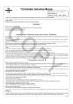
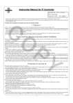
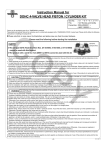
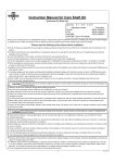
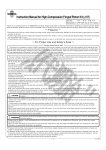
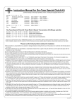
Instruction Manual for FI Controller
For Monkey (FI), Super Cub (FI), Little Cub (FI)
CO
Item No. 03−05−0019
Fits & Frame Nos
Monkey (FI) AB27-1900001∼
Super cub (FI) AA01-1700001∼
Little cub (FI) AA01-4000001∼
・Thank you for purchasing one of our TAKEGAWA’s products. Please strictly follow the instructions to install and use the products.
・Before installing the products, please be sure to check the contents of the kit. If you have any questions about the products, please kindly contact your
local TAKEGAWA dealer.
◎ Please note: Illustrations and photos may vary from actual hardware.
∼ Features ∼
○This is a subcomputer whose wires, supplied in this kit, can be connected to those of the genuine ECU with minor modification of the ECU’s wires. Thus,
this kit is easy to use and can increase the amount of fuel injection.
○This FI Controller’s 16-bit micro computer allows the air-fuel ratio of FI vehicle equipped with our S-Stage to be optimized in real time according to the engine conditions by computing the proper ratio based on the signal of the genuine computer.
○ Fuel injection can be adjusted in 15 steps with a rotary switch so that this kit can meet the modifications in the intake and exhaust system.
○This kit makes possible the fuel injection in larger amount than the maximum amount to be injected by the genuine computer.
PY
Please read the following instructions before installation.
◎ We do not take any responsibility for any accident or damage whatsoever arising from the use of this product not in conformity with the instructions in
this Manual.
◎ We do not have any information or service data on the combination of our products and other manufacturer’s products.
◎ Please note that this product is designed for exclusive use with the above-mentioned fitting models and that it cannot be mounted on any other models.
◎When ordering repair parts, please quote above Item No. or reference Nos in the figures in this Manual. If you have any questions about the repair parts,
please contact your local TAKEGAWA dealer.
◎ This product is designed to extend the fuel injection time through the incorporation of this product to the injection power from the genuine ECU.
◎ In the case of a technical trouble like the breakdown of this product or faulty wiring, it is structurally likely that the fuel injection may stop.
◎ There is no rev limiter release function.
◎The data, described in this Manual, on the increase in the fuel injection is based upon the test on the motorcycles owned by us and equipped with our products. However, when this product is installed on altered motorcycles other than those motorcycles tested by us or on motorcycles using other manufacturers’ parts as well, you may not be able to get the optimum settings for the air-fuel ratio.
◎ However, even if your motorcycle is equipped with our products, in some cases, you cannot get the intended settings because of the individual part difference, or such foreign elements as temperatures, height above sea level, or rider’s physical constitution.
◎ This product can make the general driving possible by increasing the amount of fuel injection for the vehicles with our S-Stage installed.
◎ Since this product is a subcomputer, we do not guarantee this kit that always produces perfect settings with engines of any specifications. Moreover,
we shall not be liable for the breakdown of the engine.
◎ Before driving, be sure to always check whether the air-fuel ratio, or the setting, meets your engine.
Precautions to use this kit
◎ DO NOT USE the following parts with this FI controller.
DO NOT USE H.I.D. kits in aftermarket, because many of H.I.D. kits in aftermarket emit noise of high voltage from the ballast/inverter(a device to convert
the voltage) and adversely affect the digital circuit. It causes failure or malfunction.
DO NOT USE ignition systems in aftermarket such as ignition coil or plug wire, because many of ignition systems in aftermarket increase the radiation noise
due to increase the ignition voltage. It causes malfunction or product failure.
DO NOT USE generating systems in aftermarket, because many of them cannot charge enough electricity and battery voltage lowers. Also, they cannot
control voltage. Those cause malfunctions.
◎ This product is NOT waterproof or drip-proof.
Since this product is not waterproof or drip-proof, it may damage if this controller gets wet with rain or water, or water enters the controller body.
Be careful when washing as well. Stop using the controller immediately when the controller body gets wet.
Also, be careful if you use the transparent switch panel in the kit. When it is humid or the temperature changed suddenly, the controller body may get the
moisture inside and the transparent panel fogs up.
◎ The housing of controller is plastic.
Cover the vehicle to avoid deterioration when parking the vehicle outside for a long time.
If the controller is left in the severe conditions such as hot climates for a long time, the plastic or rubber may deteriorate or deform.
◎NEVER disassemble the controller.
It•fs VERY DANGEROUS!! NEVER disassemble or modify this controller.
NOTE: If it is disassembled, we do not accept any maintenance or repair.
◎ DO NOT give an excessive impact.
DO NOT give an excessive impact to this product with riding on off-road or jumping.
By the impact, malfunctions may occur, including the breakage of the inner parts, unrepairable failure due to the disconnection or damage of the controller
housing.
◎ How to clean
If the dirt is stubborn, wipe the dirt with a soft cloth slightly moistened with a mild detergent solution and clean gently and carefully. To prevent adversely
affecting the plastic material or fogging up the panel, DO NOT use a rubbing compound or volatile solvents such as alcohol or paint thinner.
-1-
Jul./20/’
10
CAUTION
The following show the envisioned possibility of injuries to human bodies or property damage as a result of disregarding the
following cautions.
・Please drive safely and follow the local traffic laws.
・Work only when the engine and the exhaust system are cool to avoid burns.
・Prepare appropriate tools and work properly to avoid the breakage of parts or injuries.
・Always use a torque wrench to tighten bolts and nuts securely to the specified torque to avoid these parts getting damaged or loose.
・As some products and frames have sharp edges or protruding portions, work with your hands protected to avoid injuries.
・Before riding, always check such parts as screws for loose.
If you find loose ones, screw them securely up to the specified torque to avoid parts coming off.
CO
The following show the envisioned possibility of human death or serious injuries to human bodies as a result of disregarding the
WARNING following cautions.
・When you notice something abnormal with your motorcycle, stop riding immediately and park your motorcycle in a safe place to avoid an accident.
・Before working, place the motorcycle on level ground to stabilize its position for safety to avoid the motorcycle overturning.
・Please conduct checkups and maintenance correctly referring to the instructions and methods described in the instruction or service manual. (Improper checkups and maintenance could lead to accidents.)
・If you find damaged parts when inspecting or performing maintenance of your motorcycle, do not use these parts, and replace them with new ones.
(The continued use of these damaged parts could lead to accidents.)
・Keep plastic bags for packing the products out of children’s reach, or discard them.
(If children get them on, there will be a danger of their suffocating.)
◎ Please be informed that, mainly because of improvement in performance, design changes, or cost increase, the product specifications and prices are
subject to change without prior notice.
◎ This manual should be retained for future reference.
9
1、2
8
4
3
5
PY
∼ Kit includes ∼
7
6
No.
1
2
3
4
5
6
7
8
9
Part Name
FI Controller Assembly
FI Controller panel (bored switch)
FI Controller panel (transparent switch)
Rubber cap
Sub wire harness 1 COMP.
Sub wire harness 2 COMP.
Ground wire
Velcro set
Insulation lock, 150 mm
Qty
1
1※
1
1
1
1
1
1
2
Repair Part Item No.
In packs of
00-05-0044
1
00-05-0045
00-05-0041
00-05-0042
00-05-0043
00-00-0150
00-00-0135
1
1
1
1
1
10
※The FI Controller panel of Item No. 2 above with a bored switch is factory-installed onto
the FI Controller assembly of Item No.1.
Please order repair parts with the Repair Part Item No.
Without the repair part item No., we may not be able to provide the correct parts.
Some parts are only available as a set. Please order them with the set number.
∼ Product & Parts Names ∼
FI controller
Red LED
Rotary switch
Green LED
Harness for FI controller
-2-
Jul./20/’
10
∼ Installation Procedures ∼
4.Tie up the included ground wire with other stock wire harnesses
●Before installation
This product must be installed with the stock PGM-FI system which operates
properly.
If the PGM-FI system is in bad condition, this controller will not operate correctly
CO
including the ground wire gathering and connecting at one section on the frame (under the fuel tank) and route the wire with the main wire harness close to the injector.
or provide the performance, as a result it causes damage of this product or
other related parts.
To install and use this controller, make sure that your stock PGM-FI system
operates properly. Before you start working, stand your vehicle securely on
a flat surface such as a maintenance stand placed on a jack.
■ Installation on FI Monkey
1.Remove the left side cover referring to the original service manual.
2.Do the following work referring to the original service manual.
Remove the left side cover and the seat.
Bolt
5.Disconnect the 2P coupler of stock wire harness connecting the
injector.
Seat
Side cover
Nut
Grommet
Protruding portion
Screw
Hook portion
PY
6.● Go to section, “The wire connection of FI Controller”.
3.Remove the mounting bolt fixing the rear side of fuel pump to attach the
ground wire to the frame under the fuel tank.
(If you have a working stand with the same height of the frame, you can
work without removing the fuel tank.)
When removing the fuel tank, be sure to remove the fuel tank after releasing the fuel pressure in the fuel lines (referring to the service manual).
Fuel tank
Mounting bolt
Collar
Rubber
■ Installation on FI Cub/ FI Little Cub
1.Remove the leg shield referring to the original service manual.
Bolt, washer
Bolt, hook
Nut, washer
Leg shield
Set plate
Set plate
Vapor return hose
Forward
Fuel hose (low pressure)
Set bolt, washer
2.
Ground wire included in the kit is tied up at the place to ground safely with other wires and route the wire close to the injector.
Connector
Hose clamps
WARNING : As gasoline is extremely flammable, make sure NO FLAME
and NEVER leave combustible materials around the work area.
As gasoline vapors are explosive, work in a well ventilated
area and release the vapors.
CAUTION : If you work without removing the fuel tank, be careful NOT
to work the fuel hose by force.
-3-
Jul./20/’
10
3.Remove the drum cover unfastening the two fixing screws
of the throttle drum cover on the throttle body.
c.Insert colored wire (same as sub-harness) to the 2P copular.
Screws
CO
P/G
B / Bl
Drum cover
CAUTION : Make sure that the terminal should be pushed in with facing up, or the terminal will not insert into the coupler.
4.Remove the rubber coupler cover and 2P couplers of the Be careful not to insert upside down.
stock wire harness connecting injector.
6.● Go to the section, “The wire connection of FI Controller”.
Connector
5.Check to see the colors of wires from the 2P coupler of the
removed stock wire harness. If the colors of the wires and
the included sub wire harness 1COMP. are opposite in color,
do the following procedure to counterchange the places of
the wires.
CAUTION : If the wires are opposite in color, you cannot turn
on the FI controller, therefore, the engine will not
start.
◆For 2P copular on FI Cub
a.Remove the retainer(grey plastic part) from the stock coupler
with a small slotted driver.
CAUTION : Modify on chassis side copular only.
Do not modify other copular.
b.Pull out the wires individually from the coupler with a pick while pulling up the inner hook fixing the terminal of the stock
coupler. At this time, you do not have to remove the retainer
on wire side and rubber seal.
.
D
ST
.
E xt t
ec
I nj
e
T im
1.Connect the FI controller and the bullet terminal of sub wire harness referring to the
following diagram.
0123456789ABCDEF
SW. Pos.
G
PY
38775 - F C1-T 00
MADE IN JAPAN
2P coupler
●The wire connection of FI Controller
POWER
Coupler cover
ADD FUEL
To the injector
P/G
B / Bl
Sub wire harness 1COMP.
Br
Br
R
Do Not connect
Ground wire
B
To the stock wire harness
P/G
B / Bl
Sub wire harness 2COMP.
B…Black G…Green R…Red Br…Brown Bl…Blue P…Pink
Wires of FI controller
Green(Female bullet terminal)
Green(Male bullet terminal)
Brown(Male bullet terminal)
Red(Female bullet terminal)
Brown(Female bullet terminal)
Red(Male bullet terminal)
Connect to
DO NOT connect
Ground wire
Sub wire harness-1COMP. Pink/Green(Female bullet terminal)
Sub wire harness-1COMP. Black/Blue(Male bullet terminal)
Sub wire harness-2COMP. Pink/Green(Male bullet terminal)
Sub wire harness-2COMP. Black/Blue(Female bullet terminal)
2.Connect the coupler of sub wire harness 1COMP. to the injector.
Then connect the coupler of sub wire harness 2COMP. to the 2P coupler of the stock wire harness.
3.Route the wire harness of FI controller with the wire harness of the vehicle, and fasten them with the included insulation lock(Zip Tie).
Note: Install FI controller where it does not get rain or water directly such as inside
the side cover or under the seat. Use the Velcro set included in the kit to install.
4.Double check to make sure if the wiring connection is correct.
5.While looking at the switch opening on the FI controller, turn on the ignition switch.
Please check that after turning on the switch, the green and red LEDs on the switch opening light up and that the red LED goes out in about one second.
CAUTION : As we switch on all the controllers before shipment from our factory,
in case the LEDs do not light up as mentioned above, the wrong wiring can be the cause.
Immediately turn off the ignition switch, and check if there is no wrong wiring.
-4-
Jul./20/’
10
6.Install the removed exteriors in the reverse order of removal.
2.Arrow of the switch indicates a setting shown by numbers or letter.
CAUTION : Be careful NOT to pinch the wire harness in FI controller.
7.Referring to the “Recommended settings for the specified models or specs” in this page, adjust the FI controller switch at the designated setting No. which matches your engine specifications. Then, attach the
supplied rubber cap onto the switch panel.
CAUTION : Attach the rubber cap securely. If the rubber is wrongly fit on
the switch, there will be a gap between the rubber cap and
the panel of the FI controller. This may cause the rubber cap
When it shows “0”, the amount of fuel injection is almost the same as the
amount injected by the genuine ECU.(No fuel increase)
The amount of fuel injection increases more than the amount injected by
the genuine ECU following to the numbers and letters of the dial from “1”
to “F” by turning it clockwise.
3.The adjustment is a 16-step adjustment type starting from 0. Be sure to set at a figure or letter precisely until it clicks into place. (If the clicks are
incomplete, the controller does not work properly.)
to fall off or let the dust or water get into the FI controller through the gap, which may ultimately lead to the
breakdown of the FI controller.
4.When the green LED is on, this indicates that FI controller is powered.
When the FI controller is operating properly, the green LED lights up.
(The ignition switch must be “ON”.)
5.When the ignition switch is turned on, the self-diagnosis function starts
operating and the red LED lights up for one second.
However, if the red LED does not light up at all or, on the contrary, remains on, turn off the ignition switch. Please try to turn on the ignition
switch again ten seconds later.
6.Moreover, the red LED is designed to light up as a warning light when CO
●About the rubber cap and panel:
over burdening on the fuel injector while the engine is running.
If you open the throttle quickly when the engine is still cool, there is a possibility that the fuel injector may keep on injecting fuel.
This is because the FI controller works to further extend the fuel
injection time.
This kind of symptom may cause the breakdown of the fuel injector. Thus, the red LED lights up as a warning light.
Please drive your motorcycle carefully so the red LED does not light up.
PY
・Remove the rubber cap ONLY when you adjust the rotary switch.
CAUTION : If you drive your motorcycle without the rubber cap on, the dust or water may get into FI controller, causing it to break down. When riding, be sure to cover the top with the rubber ●Recommended settings for the specified models or specs
・The following table of the settings are all for the vehicles equipped with our
cap or the transparent panel in the kit.
・When the setting is finished, peel off the panel stuck on the switch at the S-Stage Kit and our Hyper Camshaft.
time of shipment from factory, and replace the panel with the transparent ・Note : These recommended settings are only the samples. They may vary
one. And this increases the dust-proof and drip-proof quality of the with external factors such as ambient temperature, altitude or rider’s weight.
product, leading to the prevention of the needless troubles.
CAUTION : When attaching the panel, please paste it right on the
octagonal recessed surface on the FI controller.
If the panel is fit on the edge, not on the recessed surface or
the groove, then the dust or water will get into the controller
through the gap.
Please place panel properly.
●How to use the FI controller and about the setting:
■Monkey (FI)
Engine specifications
Stock air cleaner box + stock exhaust system
Stock air cleaner box + TAKEGAWA Z-style exhaust system
Stock air cleaner box + TAKEGAWA Basic exhaust system
TAKEGAWA Air Filter Kit + stock exhaust system
TAKEGAWA Air Filter Kit + TAKEGAWA Z-style exhaust system
TAKEGAWA Air Filter Kit + TAKEGAWA Basic exhaust system
Setting
8
9
8
7
B
B
1.The setting of the FI controller can be adjusted by turning the yellow rotary switch.
Please turn the switch carefully with a flat extra-fine tip crewdriver
(DO NOT deform the grooves).
You can adjust the settings even when the engine is running idle.
WARNING : NEVER adjust the settings while riding. Otherwise, this may cause the consequential accidents.
■Cub (FI) and Little Cub (FI)
Engine specifications
Setting
Stock air cleaner box + Stock exhaust system
7
Stock air cleaner box + TAKEGAWA Bomber exhaust system
C
TAKEGAWA Air Filter Kit + Stock exhaust system
9
TAKEGAWA Air Filter Kit + TAKEGAWA Bomber exhaust system
F
Co.,Ltd.
3-5-16 Nishikiorihigashi Tondabayashi Osaka Japan
TEL : 81-721-25-1357 FAX : 81-721-24-5059 URL : http://www.takegawa.co.jp
-5-
Jul./20/’
10