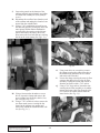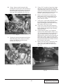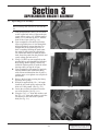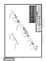
1
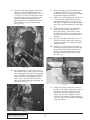
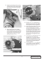
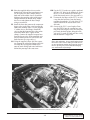
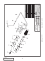
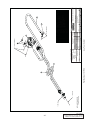
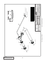
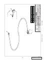
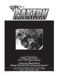
S U P E R C H A R G E R S
Owner’s Installation Guide for the
Paxton Automotive
Novi 2000 Supercharger
for the
1986-1993 5.0L Ford Mustang
Paxton Automotive . 1300 Beacon Place . Oxnard CA 93033
805 604-1336 . FAX (805) 604-1337
DP/N: 4809610 v2.0
11/14/03
© 2003 PAXTON AUTOMOTIVE
All rights recerved. No parts of this publication may be reproduced, transmitted, transcrived, or translated into
another language in any form, by any means without written permission of Paxton Automotive.
P/N: 4809610
©2003 Paxton Automotive
All Rights Reserved, Intl. Copr. Secured
05DEC03 v2.0 MusGT(4809610 v2.0)
ii
TABLE OF CONTENTS
FOREWORD . . . . . . . . . . . . . . . . . . . . . . . . . . . . . . . . . . . . . . . . . . . . . . . . . . . . . . . . . . . . . . . . . . . . .ii
TABLE OF CONTENTS . . . . . . . . . . . . . . . . . . . . . . . . . . . . . . . . . . . . . . . . . . . . . . . . . . . . . . . . . . . .iii
IMPORTANT NOTES . . . . . . . . . . . . . . . . . . . . . . . . . . . . . . . . . . . . . . . . . . . . . . . . . . . . . . . . . . . . . .iv
1.1
INTRODUCTION . . . . . . . . . . . . . . . . . . . . . . . . . . . . . . . . . . . . . . . . . . . . . . . . . . . . . . . . . .1-1
2.1
INITIAL PREPARATION AND REMOVAL . . . . . . . . . . . . . . . . . . . . . . . . . . . . . . . . . . . . . .2-1
3.1
SUPERCHARGER INSTALLATION AND ASSEMBLY . . . . . . . . . . . . . . . . . . . . . . . . . . . . .3-1
4.1
FINAL ASSEMBLY AND CHECK . . . . . . . . . . . . . . . . . . . . . . . . . . . . . . . . . . . . . . . . . . . . . .9-1
APPENDIX . . . . . . . . . . . . . . . . . . . . . . . . . . . . . . . . . . . . . . . . . . . . . . . . . . . . . . . . . . . . . . . . . . . . . .A-1
List of Appendices
. . . . . . . . . . . . . . . . . . . . . . . . . . . . . . . . . . . . . . . . . . . . . . . . . .A-2
Appendix A
1011810
KIT, PARTS LIST . . . . . . . . . . . . . . . . . . . . . . . . . . . . . . . . . . . .A-3
Appendix B
1016410
ASY, S/C NOVI 2000 FORWARD ROTATION . . . . . . . . . . . . .A-4
Appendix C
1016611
ASY, S/C MOUNTING BRACKET . . . . . . . . . . . . . . . . . . . . . .A-5
Appendix D
1016710
ASY, CRANK PULLEY . . . . . . . . . . . . . . . . . . . . . . . . . . . . . . .A-6
Appendix E
1017110
ASY, AIR INTAKE . . . . . . . . . . . . . . . . . . . . . . . . . . . . . . . . . . .A-7
Appendix F
1017010
ASY, AIR DISCHARGE . . . . . . . . . . . . . . . . . . . . . . . . . . . . . . .A-8
Appendix G
1017200
ASY, UPPER RADIATOR HOSE MODIFICATION . . . . . . . . .A-9
Appendix H
1017400
KIT, BELT TENSIONER . . . . . . . . . . . . . . . . . . . . . . . . . . . . . .A-10
Appendix I
1017702
KIT, FUEL CONTROL. . . . . . . . . . . . . . . . . . . . . . . . . . . . . . . .A-11
Appendix J
1015515
ASY, COMPRESSOR BYPASS . . . . . . . . . . . . . . . . . . . . . . . . .A-12
Appendix K
7009308
OIL RETURN . . . . . . . . . . . . . . . . . . . . . . . . . . . . . . . . . . . . . .A-13
Appendix L
7009312
ASY, OIL SUPPLY . . . . . . . . . . . . . . . . . . . . . . . . . . . . . . . . . .A-13
Appendix M
7002718
ASY, FAN SPACER . . . . . . . . . . . . . . . . . . . . . . . . . . . . . . . . . .A-13
Appendix N
7007300
ASY, SMOG PUMP MODIFICATION . . . . . . . . . . . . . . . . . . .A-13
iii
P/N: 4809610
©2003 Paxton Automotive
All Rights Reserved, Intl. Copr. Secured
05DEC03 v2.0 MusGT(4809610 v2.0)
IMPORTANT NOTES
T
his manual provides information on the installation, maintenance and service
of the Paxton supercharger kit expressly designed for the 1986-93 5.0 Ford
Mustang Contact Paxton Automotive Corporation for any additional information regarding this kit and any of these modifications at (805) 604-1336 7:00am3:45pm PST.
An understanding of the information contained herein will help novices, as well as
experienced technicians, to correctly install and receive the greatest possible benefit
from their Paxton supercharger. When reference is made in this manual to a brand
name, number, specific tool or technique, an equivalent product may be used in
place of the item mentioned. All information, illustrations and specifications contained herein are based on the latest product information available at the time of this
publication. All rights reserved to make changes at any time without notice.
P/N: 4809610
©2003 Paxton Automotive
All Rights Reserved, Intl. Copr. Secured
05DEC03 v2.0 MusGT(4809610 v2.0)
iv
RECOMMENDED TOOLS
FOR INSTALLATION:
N
ever rely solely on a hydraulic lift, when
working under a vehicle. Always use
approved jackstands to support the vehicle
and place them under the manufactures recommended lift points.
When lifting the vehicle, make sure it is on a level
surface, preferably concrete or asphalt. The transmission should be in “PARK” or “FIRST”, the
parking brake engaged, and the wheels blocked.
Never start the car with out first verifying that the
transmission is in neutral and the parking brake is
set.
Never remove the radiator cap while the engine is
still hot. Always wear eye protection when using
power tools such as drills, saws, grinders, etc., or
when working under a vehicle.
Never smoke, use an open flame, or have sparkproducing items around gasoline or flammable solvents. Always have a fire extinguisher rated for
chemical and electrical fires handy when working
on motor vehicles.
Run engines only in a well ventilated area.
Carbon monoxide, gasoline and solvent vapors are
colorless, and sometimes odorless. These can
asphyxiate or explode without warning.
Always disconnect at least the (-) negative or
ground terminal of the battery when doing any
electrical, fuel system, or under dash work.
We look forward to hearing from you, particularly
if you have any comments or suggestions regarding
this manual at (805) 604-1336 Paxton Automotive
Corporation, 1300 Beacon Place, Oxnard, CA
93033. E-mail Address:
1. Metric and Standard sockets
sets
2. Metric and Standard
bination wrenches
com-
3. Phillips and common screw
drivers
4. 12” crescent wrench or 36mm
end wrench
open
5. Pliers
6. Wire cutters and wire crimping tool.
7. Hose cutters
8. 1/8” drill bit and hand drill
37/64 drill bit
9. Allen wrenches
10. Small heat source
11. 3/8 Tap NPT
12. Air Hammer
13. Air Compressor
[email protected]
***NOTE***
Through these procedures the word “discard” is
used periodically in relationship to items that will no
longer be utilized in conjunction with the supercharger installation. It is recommended that these items be
saved for future use should it become necessary.
v
P/N: 4809610
©2003 Paxton Automotive
All Rights Reserved, Intl. Copr. Secured
05DEC03 v2.0 MusGT(4809610 v2.0)
This Page Left Intentionally Blank
P/N: 4809610
©2003 Paxton Automotive
All Rights Reserved, Intl. Copr. Secured
05DEC03 v2.0 MusGT(4809610 v2.0)
vi
Section 1
INTRODUCTION
C
ongratulations! You have purchased the
finest street Supercharger available for the
1986-1993 Ford Mustang 5.0. The centerpiece of this kit is the highly efficient and reliable
Paxton Automotive Corp. NOVI-2000 supercharger. A mechanically driven (by belt) centrifugal
supercharger.
This kit comes with all of the parts you’ll need for
a successful installation. The operations required
have been grouped in order of sequence. Photos
and drawings accompany the text, allowing quick
orientation and parts identification.
Installation requires a selection of tools which are
listed in a table at the end of this section.
We also suggest that you obtain a Ford shop manual and become familiar with the details of your cars
systems. Manuals may be obtained from your
local Ford dealer or you can order one from Helm
publications at (800) 782-4356.
For best results follow the instructions closelyand
in sequence. The average installation time for this
kit is 8-10 hours. Your actual installation time will
depend on skill level and working conditions. The
estimate does not include time for initial vehicle
inspection, cleaning, fine
tuning or troubleshooting. Before even picking up
a wrench, read this entire manual. We are available
for technical assistance at
(805) 604-1336, 7am-3:30pm pacific time.
After reading the manual, verify that all major
assembly groups are present in the main kit box.
You should have ample space to layout the components. As you remove a box or bag from the main
kit, note the identification label
and compare it with the parts list. Please check the
box for small parts.
Paxton makes every effort to insure that all parts
are included in the box. However, if you discover
any missing or mislabeled parts, please contact
Paxton by phone for service.
***WARNING***
DO NOT attempt installation if any part(s) are missing from this kit. Failure to contact Paxton prior to
beginning installation will result in a charge for any
missing parts.
Before starting the installation, we suggest your
engine compartment be clean. You can clean the
engine and compartment with a pressure washer
(such as those used at self serve car washes) and a
safe-for-aluminum cleaner/degreaser. Cover the
distributor with a plastic bag to prevent water from
entering.
***CAUTION***
We do not recommend proceeding with the kit installation unless your vehicle is within normal operating
parameters.
You are undoubtedly enthusiastic about getting
started on your project, but take just a little more
time to insure that your safety is not jeopardized. A
moment’s lack of attention can result in an accident, as can failure to observe certain simple safety
precautions. The possibility of an accident will
always exist, and the following points should not
be considered a comprehensive list of all dangers.
Rather, they are intended to make you aware of the
risk and to encourage a safety conscious approach
to all work you do on your vehicle.
1-1
P/N: 4809610
©2003 Paxton Automotive
All Rights Reserved, Intl. Copr. Secured
05DEC03 v2.0 MusGT(4809610 v2.0)
This Page Left Intentionally Blank
P/N: 4809610
©2003 Paxton Automotive
All Rights Reserved, Intl. Copr. Secured
05DEC03 v2.0 MusGT(4809610 v2.0)
1-2
Section 2
INITIAL PREPARATION AND REMOVAL
B
egin the initial preparation and disassembly
process by disconnecting the battery cables.
2.1
Fuel tank/Fuel pump removal
A. The installation of a higher flowing fuel
pump is necessary. Before the removal of
the fuel tank, be sure the fuel tank is completely empty.
B. Using a hydraulic lift, lift the rear of the
Vehicle up and place securely on jack
stands.
C. Remove the three 10mm hex head sheet
metal screws securing the fill pipe to the
quarter panel. (See Fig. 2-a.)
Fig. 2-b
Disconnect the three hoses using the supplied fuel fitting removal tools (fuel feed,
fuel return and fuel vapor) up in front of the
fuel tank.
F. Twist the retainer ring that is securing the
fuel sending unit in the top of the tank. Lift
the pickup/sending unit assembly out of the
tank.
G. Carefully pry off the sock on the end of the
pump. Remove the pump from the assembly
and install the new pump (it should be a
direct replacement). Reinstall the sock on
the new pump.
H. Replace the assembly into the tank and
secure it with the retainer ring. Be certain
that the O-ring is in its proper place and that
the ring is turned all the way to its stop position.
I. Plug the wires/hoses back in and re-install
the fuel tank back up into the vehicle.
E.
Fig. 2-a
D. Place a jack underneath the fuel tank to
lightly hold pressure on the tank to assist in
the lowering of the tank and removal of the
retainment straps. (See Fig. 2-b.) When the
gas tank is on the ground unplug the fuel
pump and sensor wires, from the sending
unit.
2-1
P/N: 4809610
©2003 Paxton Automotive
All Rights Reserved, Intl. Copr. Secured
05DEC03 v2.0 MusGT(4809610 v2.0)
Loosen the petcock at the bottom of the
radiator and drain approximately one gallon
of coolant into a drain pan. (Save fluid for
re-use.)
K. Disconnect the overflow hose from the neck
of the radiator and unplug the electrical connector from the coolant bottle.
L. Using a 7/16" combination wrench, loosen
the four bolts that are securing the fan to the
water pump. With an18mm combination
wrench release the tension on the belt tensioner and remove the factory drive belt.
Now remove the four bolts that are securing
the fan to the water pump. (See Figs. 2-c.)
J.
Fig. 2-d
Fig. 2-e
O. Using a nut driver or screwdriver, remove
the clamps securing the rubber inlet tube to
the throttle body and mass air flow sensor
and remove the inlet tube.
P. Loosen the clamp securing the mass air flow
sensor to the rubber sleeve at the air filter
assembly. Unplug the sensor and un-bolt it
from the strut tower with a 7/16" socket.
Q. Using a 7/16" deep socket, loosen the nuts
securing the air filter assembly to its rubber
mounts and remove the filter from the vehicle. Unscrew the rubber mounts from the
inner fender. (See Fig. 2-f.)
Fig. 2-c
M. Using a 10mm socket & ratchet or screw
driver, loosen the clamps and remove the
upper radiator hose from the vehicle. Save
for re-use.(See Fig. 2-d.)
N. Using a 7/16" wrench or socket, remove the
two sheet metal screws securing the fan
shroud to the radiator core support and
remove the shroud fan clutch from the vehicle. (See Fig. 2-e.)
Fig. 2-f
P/N: 4809610
©2003 Paxton Automotive
All Rights Reserved, Intl. Copr. Secured
05DEC03 v2.0 MusGT(4809610 v2.0)
2-2
Using a 5/16” nut driver, loosen the clamps
and remove the air injection hose from the
smog pump and diverter valve up next to the
valve cover. Disconnect the vacuum line
behind the smog pump and remove the hose
from the vehicle. Set aside for re-use
U. Remove the bolt at the rear of the smog
pump using a 9/16" socket and the two at
the front of the pump, remove the smog
pump from the vehicle.
T.
R. Using a 19mm wrench, loosen the bolt
securing the accessory drive belt tensioner to
the factory bracket and remove the tensioner
from the bracket. Set aside to be used in a
later step of the installation. (See Fig. 2-f.)
Using a 9/16" socket and extension, remove
the remaining bolts securing the factory
bracket to the engine. Set the bracket aside,
this bracket will not be re-used.
W. Using a 9/16" deep socket and extension,
remove the fuel line bracket from the front
head retaining stud and un-clip it from the
factory fuel lines.
X. On the frame rail, there is an evaporator
canister. From underneath the vehicle, use a
1/2" socket and remove the two bolts securing the canister bracket to the frame rail.
Reposition the canister forward, towards the
front of the vehicle, using one of the stock
bolts. Resecure the canister to the frame rail
using the forward hole in the frame rail and
the rear hole in the bracket.
Y. Remove the four factory crank pulley bolts
with a 9/16" socket and extension and
remove the pulley from the vehicle. (See
Fig. 2-h.)
V.
Fig. 2-f
S.
Unplug the electrical connection at the alternator, and using a 9/16" and a 1/2" socket,
remove the alternator from the factory
bracket. (See Fig. 2-g.)
Fig. 2-g
Fig. 2-h
2-3
P/N: 4809610
©2003 Paxton Automotive
All Rights Reserved, Intl. Copr. Secured
05DEC03 v2.0 MusGT(4809610 v2.0)
This Page Left Intentionally Blank
P/N: 4809610
©2003 Paxton Automotive
All Rights Reserved, Intl. Copr. Secured
05DEC03 v2.0 MusGT(4809610 v2.0)
2-4
Section 3
SUPERCHARGER BRACKET ASSEMBLY
3.1
Supercharger kit Assembly
***IMPORTANT***
Before continuing drain the motor oil from the vehicle.
A. From underneath the vehicle you will need
to drill a pilot hole in the oil pan on the passenger side by using a 1/8" drill bit approximately 1-1/2" from the top and 2" from the
front of the oil pan. (See Fig. 3-a.)
B. Upon completion of the drilled pilot hole,
insert a rigid thin piece of wire through the
drilled pilot hole to ensure that there is a
straight shot for the punch to go into. If
there is anything blocking the path, rotate
the engine by hand using the appropriate
size socket and ratchet, to rotate the crankshaft. Insert the punch into the pilot hole and
evenly enlarge the hole to 9/16".
C. Using a 3/8 NPT tap (not supplied) tap the
punched hole to accommodate the threaded
brass fitting. Before tapping, coat the tap
with thick lithium grease to retain the metal
shavings while you tap the oil pan.
D. Upon completion of the tapped oil pan hole,
coat the threaded end of the brass fitting
with silicone and thread into the oil pan, be
cautious not to over tighten or to strip the oil
pan threads.
E. Remove the four bolts securing the factory
accessory drive pulley.
F. With the 4 supplied bolts 3/8 x 1 in length
install the new crank pulley and torque the
bolts to 25-28ft pounds. (See Fig. 3-b.)
G. Locate the two bolts insert these from the
rear of the bracket. (See Fig. xxx.)
H. Using the 7/16” x 1” bolts and washers, and
the 3/8” x 1.5” bolts and washers, secure the
cast bracket to the front of the cylinder
head.(See Fig. 3-c.)
Fig. 3-a
Fig. 3-b
Fig. 3-c
3-1
P/N: 4809610
©2003 Paxton Automotive
All Rights Reserved, Intl. Copr. Secured
05DEC03 v2.0 MusGT(4809610 v2.0)
G. Using the main Supercharger bracket bolt it
onto the previously installed cast bracket
using two of the bolts that measure 3/8" x 6
3/4" and two of the flat washers these bolts
will go through the lower two holes on the
main S/C bracket then through the cast
bracket, and into the cylinder head threads.
Do not tighten yet, just get them started.
(See Fig. 3-d.)
Below the smog pump, The alternator will
be mounted. Use the 7/16" x 4" bolt and
washer through the mounting plate, through
the alternator and into the bracket.
J. Off the side of the Smog pump, Use the 3/8"
x 1" bolt and the supplied lock washer to
mount the alternator stay. Use the 3/8" x 1"
bolt and lock washer to secure the alternator
stay to the ear of the alternator. Do not tighten.
K. Following the accessory belt routing diagram, (see Appendix C) route the belt
around the pulley’s. This will have to be
moved later, however it is necessary to put
the belt in place before the support plate is
installed.
L. Insert the solid idler, arbor and 1/2"-13 x 3"
allen bolt into the lower corner of the support plate with the 1/2" nut and flat washer.
Tighten this bolt.
M. Attach the 1/2" drain hose to the nipple at
the bottom of the supercharger. Secure with
the provided clamp. Route the hose down
the side of the engine and connect to the
nipple previously installed in the oil pan.
(See Fig. 3-f.)
I.
Fig. 3-d
H. The Smog pump is secured with a 3/8" x 5"
bolt and flat washer, from the front, through
the mounting plate, through the smog pump
spacer, through the smog pump and into the
bracket boss. The lower mounting is done
with a 3/8 x 2" bolt and washer from the
back of the bracket into the smog pump. Do
not tighten. (See Fig. 3-e.)
Fig. 3-f
N. Remove the factory oil pressure sensor at
the front of the engine on the drivers side of
the engine next to the oil filter. Use pipe
sealant and install the supplied street tee
adapter into the factory fitting where the
sensor was. Re-install the factory sensor on
one of the ends of the street TEE and tighten
using pipe sealant.
Fig. 3-e
P/N: 4809610
©2003 Paxton Automotive
All Rights Reserved, Intl. Copr. Secured
05DEC03 v2.0 MusGT(4809610 v2.0)
3-2
O. Install the steel braided -4 oil line on to the
-4 fitting of the street TEE. Neatly route the
hose across the front of the engine, behind
the accessories and under the supercharger.
(See Fig. 3-g.)
Fig. 3-i
Q. Install the 3/8" x 2 1/2" countersunk bolt
through the lower most hole in the support
plate and thread it into the mounting plate.
Do not tighten this bolt. (See Appendix B.)
R. Above that, insert two of the 3/8" x 3 1/4"
bolts with washers through the support plate,
spacer and mounting plate. Secure the
accessory drive belt tensioner to the back of
the mounting plate with the upper of these
two bolts holes, the lower with the 3/8" x 1"
bolt and washer provided. Secure the other
side of the belt tensioner bracket to the stud
at the top of the water pump with the 3/8"
nut and washer. Do not tighten these bolts.
(See Fig. 3-i)
Fig. 3-g
P.
Bolt the Supercharger to the mounting
bracket with one of the 3/8" x 1" bolts and
washers through the upper most hole and the
two lower holes in the mounting plate. Place
the support plate over the front of the supercharger and secure with the 3/8" countersunk bolts. (See Fig. 3-h, 3-i.)
S.
T.
There are three (3) countersunk holes left in
the support plate. They each take the
remaining 3/8" x 3 1/4" counter sunk bolts.
Install these bolts and tighten to 28-30 ft
pounds. Upon completion of this step, tighten all of the remaining bolts that have been
left hand tight, as well as the Smog and
alternator assemblies.
Use the supplied 1/2" x 3 1/2" carriage bolt,
nut and washer to secure the factory belt
tensioner to the new bracket. Tighten nut to
28-30 ft lbs.. (See Figs. 3-j, 3-k.)
ATTACH THE OIL HOSE FROM THE
STREET TEE TO THE FITTING ON
THE SIDE OF THE SUPERCHARGER
Fig. 3-h
3-3
P/N: 4809610
©2003 Paxton Automotive
All Rights Reserved, Intl. Copr. Secured
05DEC03 v2.0 MusGT(4809610 v2.0)
the end of the adjustable idler so that it will
not back off.
X. Find the rubber air injection hose from the
diverter valve removed in an earlier step.
Shorten the hose by cutting 3" out of the
middle of the hose and 1-1/2" off the back
end of the hose. Reconnect the two formed
pieces together with the sleeve and clamps
provided. Re-install the short end hose
between the diverter valve and fitting on the
side of the smog pump.
Y. Cut the upper radiator hose. Re-install the
longer piece on the thermostat housing
angled forward. Install the shorter 90º
degree piece on the radiator angled to the
side. Install the stainless tube between the
two pieces of hose and secure with the supplied clamps. (See Fig. 3-l.)
Fig. 3-j
2"
3"
2"
3"
Fig. 3-l
Remove the vent tube from the throttle body
and the oil fill cap and clamp, plug the nipple on the throttle body with a nipple plug
and using a hose clamp securely retain the
nipple cover.
AA. Install the intake u-bend with the supplied 3
1/2" x 4" adapter sleeve and clamps. On the
other end of the U-bend, install the 3 1/2" x
3 1/4" adapter sleeve. (See Appendix E.)
BB. Plug in the Mass air flow (MAF) sensor and
install the sensor into the opposite side of
the adapter sleeve with the supplied clamps.
(see Appendix E)
CC. Install the K&N air filter on the end of the
MAF sensor. Tighten the clamp to secure the
filter. (See Appendix E.)
DD. Install the brass fitting into the hole in the
front of the filter cover and tighten. Place
the filter cover over the filter and secure it to
the inner fender with the supplied screws.
Install the supplied crankcase breather hose
on this nipple and route it back to the oil
filler cap. Trim to fit and install this end of
the hose to the nipple on the side of the oil
fill spout clamp to secure.
Z.
Fig. 3-k
U. Install the new fan spacer on the water
pump. Place the fan and shroud back into
the engine compartment together. Re-install
the factory fan and clutch using the 5/16"
bolts and washers. Tighten with a 1/2"
wrench to the factory specifications. Use
the factory screws to re-install the shroud
onto the radiator core support.
V. Use an 18mm wrench to rotate the accessory
belt tensioner and reinstall the factory belt in
the correct routing. (See Appendix C.)
W. Install the supercharger drive belt between
the crank pulley and the supercharger pulley.
Route the belt inside the idlers. Use a 3/8"
socket and extension and tighten the belt.
Once the belt is tensioned, tighten the nut on
P/N: 4809610
©2003 Paxton Automotive
All Rights Reserved, Intl. Copr. Secured
05DEC03 v2.0 MusGT(4809610 v2.0)
3-4
EE. Place the supplied rubber sleeves on the
throttle body inlet and the supercharger outlet. Now place two hose clamps each on
both ends of the rubber sleeves. Install the
discharge duct onto the outlet of the supercharger and then the throttle body. Adjust
the sleeves and tighten the hose clamps
using a screwdriver.
FF. Install the hose that connects the compressor
bypass valve to the filter cover between the
intake and discharge tubes. Use the supplied
1" rubber sleeves and clamps. Install the
valve so that the bottom of the valve points
toward the intake duct. Tighten all the
clamps. Connect the supplied vacuum hose
from the bypass valve to the manifold vacuum tree located on the fire wall next to the
brake booster. (See Appendices.)
GG. Using the supplied yellow fuel line separator, separate the return line fitting at the fuel
rail. Snap the two supplied rubber hoses
onto the stock fittings and route both hoses
behind the passenger side strut tower.
HH. Use the F.C.U. bracket as a guide, mark and
drill two 1/8" holes in the fenderwell. Secure
the F.C.U. to the fenderwell with the supplied sheet metal screws. (See Appendices.)
II. Connect the fuel hoses to the F.C.U. in such
a way that the fuel flows from the factory
regulator, through the “in” side of the F.C.U.
out the bottom of the outside back to the
fuel tank.
JJ. On top of the F.C.U. run a length of hose
over and TEE it into the vacuum hose running to the boost bypass valve. Re-using the
previously drained coolant, bring the reservoir up to it’s stock fill limit, and also verify
that the radiator is topped off.
***IMPORTANT NOTE***
Due to tight tolerances , be very careful when closing
the hood for the first time, making sure that there is
not any interference between the s/c and the hood of
the car. By doing this you will eliminate damaging
your vehicle and/or supercharger.
Completed Installation on a 5.0L Ford Mustang Motor
3-5
P/N: 4809610
©2003 Paxton Automotive
All Rights Reserved, Intl. Copr. Secured
05DEC03 v2.0 MusGT(4809610 v2.0)
This Page Left Intentionally Blank
P/N: 4809610
©2003 Paxton Automotive
All Rights Reserved, Intl. Copr. Secured
05DEC03 v2.0 MusGT(4809610 v2.0)
3-6
Section 4
FINAL CHECK OUT AND START UP
4.3
This section covers pre-start checks and inspections, as well as initial start-up.
4.1 Inspect the following:
A.
B.
C.
D.
A. Wires, harnesses and electrical connections.
Are all items properly dressed, connected
and secured? If any electrical connections
have been dis-connected, re-connect them
before you start your vehicle.
B. Hoses, lines and fittings. Are all items properly dressed, connected and secured?
C. Fasteners, brackets, and clamps. Are all
items properly installed and tightened?
D. Fluid levels. Is the radiator coolant and the
engine oil at their proper levels? Are there
any fluid leaks?
C. Belt(s). Is the serpentine drive belt (or
accessory drive and supercharger drive belts,
depending on the requirement of your vehicle) properly installed, aligned and tensioned?
4.2
Check for the following:
Fuel leaks.
Fluid leaks.
Belt slippage.
Throttle response.
***CAUTION***
See the supercharger service manual included in
your kit for information on supercharger servicing
and maintenance, belt tightening, troubleshooting,
special tuning, and warranty information.
Now that the work is down, it’s time to enjoy
your labor of love. Take the car out on the road
and let it flex it’s muscles, but remember, the
response and performance will now be different
from that to which you have been accustomed.
Have fun!
Perform the following:
A. Cycle the ignition key from “off “ to “on”
position three (3) times at fifteen (15) second intervals. Afterwards, check the entire
fuel system for any leaks.
B. Start the car. Verify that the oil pressure is
within the normal operating range. Listen
closely. The engine should idle and sound
the same as it did before you began the
installation. Shutdown the engine, disconnect the oil feed line from the blower.
Remove the oil jet from the blower. Blow
through the oil jet to ensure there is no
blockage or foreign matter plugging it. Reinstall oil jet and oil feed line and proceed.
C. Allow the engine to come to normal operating temperatures. Bleed the cooling system
and top off as necessary.
4-1
P/N: 4809610
©2003 Paxton Automotive
All Rights Reserved, Intl. Copr. Secured
05DEC03 v2.0 MusGT(4809610 v2.0)
This Page Left Intentionally Blank
P/N: 4809610
©2003 Paxton Automotive
All Rights Reserved, Intl. Copr. Secured
05DEC03 v2.0 MusGT(4809610 v2.0)
4-2
Appendix
P
lease realize that PAXTON Automotive is constantly improving the performance and look of the NOVI 2000 supercharger. Parts in your kit may appear
differently than what is pictured in this manual. This is due to photographs
taken in pre-production, a change in material costs, or an improvement in performance.
Rest assured that you have purchased to best quality kit that PAXTON Automotive
manufactures at this time. The installation of the materials will remain the same.
Appendix Part Number
Description
Page
1
#1016410
Asy, 96-93 5.0L Novi 2000
A-2
2
#1016611
Asy, Mtg Brkt 5.0L Novi 2000
A-3
3
#1016710
Asy, Crank Pulley, 86-93 5.0L Novi 2000
A-4
4
#1017010
Asy, Air Discharge, 86-93 5.0L Novi 2000
A-5
5
#1017110
Asy, Air Intake, 86-93 5.0L Novi 2000
A-6
6
#1017702
Asy, Fuel Control
A-7
7
#1015515
Asy, Compressor Bypass
A-8
8
#1019312
Asy, Oil Supply
A-9
9
#1017300
Asy, Smog Pump Modification
A-10
A-1
P/N: 4809610
©2003 Paxton Automotive
All Rights Reserved, Intl. Copr. Secured
05DEC03 v2.0 MusGT(4809610 v2.0)
P/N: 4809610
©2003 Paxton Automotive
All Rights Reserved, Intl. Copr. Secured
05DEC03 v2.0 MusGT(4809610 v2.0)
A-2
13
14
12
ALIGN VOLUTE WITH
1/2 HOLE SHOWN
11
10 SHORT HUB
TOWARD S/C
S/C ROTATION
8
9
2
4
1
AS REQD
31 30 29 25 2
3
Part Number: 1016410
7
6
?
4 REQD 19
AS REQD
28 27 26 2
3
7
20 2 4
21
22 3
NONE
APPR.
WEIGHT
----21.8 LBS
-----
Supercharger Asy, 86-93 5.0 Novi 2000
FINISH
SCALE:
SIZE
86-93 5.0L MUSTANG
REV.
B
SHEET 1 OF 1
1300 BEACON PLACE OXNARD, CA 93033
TEL: (805) 604-1336 FAX: (805) 604-1337
DESCRIPTION
ASY, GEARCASE, NOVI 2000, CW
FTG, NIPPLE, 3/8NPT x 1/2 HOSE BARB
FTG, PLUG, 3/8NPT WITH MAGNET
WASHER, COPPER CRUSH, 3/8
OIL JET, LONG
SCREW, SCHD, 3/8-16UNC-2A x 1.00 LG.
CAP, SHIPPING, T2
KEY, 1/8 SQ x 1.25 LG.
SPACER, PULLEY, .125 THK.
PULLEY, S/C 10 GRV, 3.50
RET, CUP BLWR PULLEY
RET, PULLEY, S/C 3/8
CAP, TAMPER PROOF
SCREW, HXHD, 3/8-24UNF-2A x 1.00 LG.
VOLUTE, NOVI 2000, CRV DIS, CW
CAP, SHIPPING, 3"
CAP, SHIPPING, 4"
NAMEPLATE, NOVI 2000
SCREW, DRIVE, #4 x .187 LG.
IMPELLER, NOVI 2000, CW , BALANCED
WASHER, ANTI-ROTATION
NUT, 3/8-24UNF-2B, FLG LOCK
CLAMP, VOLUTE
SCREW, SCHD, 1/4-20UNC-2A x .50 LG.
MATING RING, .090 THK.
SHIM, IMP, .003 THK.
SHIM, IMP, .005 THK.
SHIM, IMP, .010 THK.
MATING RING, .099 THK.
MATING RING, .103 THK.
MATING RING, .112 THK.
3:4
DO NOT SCALE DRAWING
ASY, S/C NOVI 2000
FORWARD ROTATION, 86-93 5.0L, SATIN
DWG. NO.
1016410
D
ITEM NO. QTY.
PART NO.
2H238-000
1
1
7PP375-017
1
2
7P375-016
2
3
7J375-024
2
4
7PP375-090
1
5
7P375-104
1
6
008704
2
7
7U100-075
2
8
2H017-125
2
9
4PFA031-350
1
10
2H040-021
1
11
2H040-011
1
12
008718
1
13
7B375-110
1
14
2H018-051
1
15
008706
1
16
008719
1
17
2H100-035
1
18
7U100-021
4
19
2H021-051
1
20
2H017-021
1
21
7G010-155
1
22
2H100-045
3
23
7A250-050
6
24
2
2H060-030
0
25
2H100-003
0
26
2H100-005
0
27
2H100-010
0
28
2H060-031
0
29
2H060-040
0
30
2
2H060-041
0
31
17
16
UNLESS OTHERWISE SPECIFIED
CAD GENERATED DRAWING,
DIMENSIONS ARE IN INCHES
DO NOT MANUALLY UPDATE
TOLERANCES ARE: .XX± .01
DECIMALS:
.XXX±.005
DATE
APPROVALS
±1/2•
FRACTIONS:
DRAWN
DTP
6/3/97
ANGLES:
±1/16
ENGINEERING
--------MATERIAL
R&D
SEE PARTS LIST
---------
26 6 REQD
23 3 REQD
5 4
15 2
A-3
P/N: 4809610
©2003 Paxton Automotive
All Rights Reserved, Intl. Copr. Secured
05DEC03 v2.0 MusGT(4809610 v2.0)
18
17
13
17 25
25
19
10
17
12
11
30
17
5
15 17
4
9
8
6
14
2
24
31
17 20
Part Number: 1016611
15
19
17 16
4
31
7
32
25 14
3
31 27
17 22
33 17
FINISH
APPR.
WEIGHT
-----
-----
-----
Asy, Mounting Bracket 5.0 Novi 2000
NONE
DO NOT SCALE DRAWING
ASY, S/C MTG BRKT
'86-'93 MUSTANG 5.0L w/NOVI 2000
DWG. NO.
1016611
D
SCALE: 1:1.5
SIZE
1300 BEACON PLACE OXNARD, CA 93033
TEL: (805) 604-1336 FAX: (805) 604-1337
DESCRIPTION
MTNG BRCKT, S/C
PLATE, FRONT
PLATE, REAR
SPACER, 875 x 1.482 L
3/8-16 x 2 1/2 FL SHCS
IDLR SCREW
SCREW, IDLR ADJR
5/16-18 x 3/8 HHCS-SS
ARBOR, SC TENS PLY
3/8-16 x 1.0 FL SHCS
3/8-16 x 3.0 F HD
COLLAR, 10 RIB PLY, NOVI
PULLEY, IDLR SMOOTH
WASHER, 3/8 SAE PLTD
3/8-16 x 3 HXCS
3/8-16 x 1-1/4 HXHD
WASHER, 1/2 ID x 1.12 OD
1/2-20 x 3 HXHD
1/2-20 x 1.5 HHCS
3/8-16 x 7 HXHD
3/8-16 x 6.75 HXHD
3/8-16 x 1.75 HXHD
SCREW, HXHD,3/8-16UNC-2A x 6.25 LG.
SPACER, ALT BRCKT
3/8-16 x 1 HXHD
3/8-16 x 2 HXHD
7/16-14 x 1.75 HXHD
7/16 SAE WASHER
SPACER, SMOG
ALTERNATOR STAY
3/8-16 HX NUT
LABEL, ALTERNATOR DATA
3/8-16 x 6.50 HXHD
REV.
L
SHEET 1 OF 1
99-01 3.5L PLYMOUTH PROWLER WITH UPGRADE
ITEM NO. QTY.
PART NO.
1
4FA011-021
1
2
4PFA010-054
1
3
4PFA010-044
1
4
2A017-875-11
4
5
7A375-251
1
6
4PFA010-031
1
7
7PA375-500
1
8
7A250-077
2
9
7PB500-263
1
10
7A375-102
3
11
7A375-302
2
12
4PFA017-011
2
13
1210508
2
14
7J375-044
16
15
7A375-300
3
16
7A375-124
3
17
7J500-001
3
18
7B500-300
1
19
7F500-025
2
20
7A375-751
1
21
7A375-675
1
22
7A375-175
1
23
7A375-625
1
24
4PFA017-071
1
25
7A375-100
3
26
7A375-200
1
27
7A437-175
1
28
7J438-081
1
29
4FA017-021
1
30
4FA015-015
1
31
7F375-016
2
32
4832500
1
33
7A375-650
1
23 17
UNLESS OTHERWISE SPECIFIED
CAD GENERATED DRAWING,
DIMENSIONS ARE IN INCHES
DO NOT MANUALLY UPDATE
TOLERANCES ARE: .XX± .01
DECIMALS:
.XXX±.005
DATE
APPROVALS
±1/2•
FRACTIONS:
DRAWN
TAP
01/27/03
ANGLES:
±1/16
ENGINEERING
--------MATERIAL
R&D
SEE PARTS LIST
---------
14
21 17
29
1
17 26
P/N: 4809610
©2003 Paxton Automotive
All Rights Reserved, Intl. Copr. Secured
05DEC03 v2.0 MusGT(4809610 v2.0)
A-4
S
PU /C
LL
EY
NS
I
PU ONER
LL
EY
TE
PART OF 1016410
4
Part Number: 1016710
PART OF 1016610
OG
PU PUM
LL
EY P
SM
3
TO CRANKSHAFT
1
ITEM QTY
1
1
2
4
3
4
4
1
5
1
6
1
5
NONE
WEIGHT
APPR.
--- LBS
-----
-----
Asy, Crank Pulley 86-93 5.0 Novi 2000
FINISH
C
8/14/01
DO NOT SCALE DRAWING
DWG. NO.
ASY, CRANK PULLEY
'86-'93 MUSTANG 5.0L w/NOVI
REV.
F
SHEET 1 OF 1
1300 BEACON PLACE OXNARD, CA 93033
TEL: (805) 604-1336 FAX: (805) 604-1337
PARTS LIST
DESCRIPTION
PULLEY, CRANK 10 GRV 7.034 P DIA
SCREW, 3/8-16 x 1.00 SHCS GR8
WASHER, FLAT 3/8 AN960-616
BELT, S/C DRIVE 10 GRV POLYCOG 1441mm x 35.7mm
BELT, ACCESSORY DRIVE 6 GRV MICRO-V 2525mm x 21mm
STICKER, BELT ROUTING
WE
PU R ST
MP EER
PU ING
LL
EY
PO
SCALE: NONE
SIZE
PART NUMBER
8002615
4815801
1046290
4831232
4831201
4813000
UNLESS OTHERWISE SPECIFIED
CAD GENERATED DRAWING,
DIMENSIONS ARE IN INCHES
DO NOT MANUALLY UPDATE
TOLERANCES ARE: .XX± .01
DECIMALS:
.XXX±.005
DATE
APPROVALS
±1/2•
FRACTIONS:
DRAWN
CFB
8/14/01
ANGLES:
±1/16
ENGINEERING
--------MATERIAL
R&D
SEE PARTS LIST
---------
2
AL
PU T
LL
EY
CO A/C
MP
RE
PU SSOR
LL
EY
WA
TE
R
PU PUM
LL
EY P
CE
TE SSOR
NS
IO Y
PU NER
LL
EY
AC
A-5
P/N: 4809610
©2003 Paxton Automotive
All Rights Reserved, Intl. Copr. Secured
05DEC03 v2.0 MusGT(4809610 v2.0)
4
TO COMPRESSOR BYPASS ASY
Part Number: 1017010
1
3
3
2
TO S/C ASY
3
QTY.
1
2
4
1
ITEM NO.
1
2
3
4
TO THROTTLE BODY
PART NO.
FINISH
WEIGHT
2.6 LBS
-----
-----
Asy, Air Discharge 5.0 Novi 2000
NONE
APPR.
SCALE:
SIZE
7P750-100
7R002-048
7PS300-200
4PFA012-031
UNLESS OTHERWISE SPECIFIED
CAD GENERATED DRAWING,
DIMENSIONS ARE IN INCHES
DO NOT MANUALLY UPDATE
TOLERANCES ARE: .XX± .01
DECIMALS:
.XXX±.005
DATE
APPROVALS
±1/2•
FRACTIONS:
DRAWN
DTP
5/29/97
ANGLES:
±1/16
ENGINEERING
--------MATERIAL
R&D
SEE PARTS LIST
---------
3
2
1:2
C
1017010
DO NOT SCALE DRAWING
DWG. NO.
ASY, AIR DISCHRGE
86-93 5.0L MUSTANG
REV.
C
SHEET 1 OF 1
1300 BEACON PLACE OXNARD, CA 93033
TEL: (805) 604-1336 FAX: (805) 604-1337
FTG, NIPPLE, 3/4NPT X 1.00 HOSE BARB
CLAMP, HOSE #48
SLV, BLK, 3.00D X 2.00
TUBE, DISCHARGE
DESCRIPTION
7
11
2
10
1
A-6
P/O
3
5
TO S/C INLET
9
Part Number: 1017110
STOCK M.A.F.
9
5
14
4
12 TO WHEEL WELL
8
13
TO OIL FILL
BREATHER
6
FINISH
WEIGHT
--- LBS
-----
Asy, Air Intake 5.0 Novi 2000
NONE
APPR.
8
-----
C
SCALE: NONE
SIZE
ITEM QTY PART NO.
1
1 4PFA012-010
2
1 7PS350-301
3
1 7PS400-200
4
1 4PFA013-010
8H040-050
5
1
8H040-020
6
1
7P750-100
7
1
8 1.6' 7U030-056
7R002-064
9
2
7R002-048
10
1
7R002-056
11
1
7E010-052
12
2
7P250-047
13
1
14
1
3863517
UNLESS OTHERWISE SPECIFIED
CAD GENERATED DRAWING,
DIMENSIONS ARE IN INCHES
DO NOT MANUALLY UPDATE
TOLERANCES ARE: .XX± .01
DECIMALS:
.XXX±.005
DATE
APPROVALS
±1/2•
FRACTIONS:
DRAWN
DRB
07/10/97
ANGLES:
±1/16
ENGINEERING
--------MATERIAL
R&D
SEE PARTS LIST
---------
TO WHEEL
12
WELL
PA
A XT
C UT ON
O
RPOMOT
OR IV
ATI E
ON
P/N: 4809610
©2003 Paxton Automotive
All Rights Reserved, Intl. Copr. Secured
05DEC03 v2.0 MusGT(4809610 v2.0)
1017110
DO NOT SCALE DRAWING
DWG. NO.
ASY, AIR INTAKE
'86-'93 MUSTANG 5.0L w/NOVI
REV.
F
SHEET 1 OF 1
1300 BEACON PLACE OXNARD, CA 93033
TEL: (805) 604-1336 FAX: (805) 604-1337
PARTS LIST
DESCRIPTION
TUBE, AIR INTAKE MACHINED '86-'93 MUST 5.0L
HOSE, REDUCER 3.5" x 3"
HOSE, TURBO 4" x 2" LG
COVER, AIR INTAKE FILTER
FILTER, AIR HIGH FLOW w/CLAMP 3.5" INLET
FILTER, FUEL 3/8 TUBE ENDS
FTG, NIPPLE 3/4 NPT x 1" HOSE BARB
HOSE, FUEL 3/8 x 20" LG
CLAMP, HOSE #64
CLAMP, HOSE #48
CLAMP, HOSE #56
SCREW, #10 x .50 PAN HEAD SHEET METAL
FTG, ELBOW 90° 1/4 NPT x 3/8 HOSE BARB
DECAL, KIT IDENTIFICATION '86-'93 MUSTANG 5.0L
A-7
P/N: 4809610
©2003 Paxton Automotive
All Rights Reserved, Intl. Copr. Secured
05DEC03 v2.0 MusGT(4809610 v2.0)
NOTES: UNLESS OTHERWISE SPECIFIED
1. TO BE SHIPPED LOOSE
TO FUEL RAIL
TO GAS TANK
Part Number: 1017702
4
3
1
1
1
1
1
ITEM NO.
2
3
4
6
7
8
9
10
11
12
13
QTY.
2
1
1
1
2
1
1
1
1
1
1
11
FINISH
NONE
3.6 LBS
G. COMPTON
Asy, Fuel Control
WEIGHT
APPR.
10/4/01
13
12
D
1017702
DO NOT SCALE DRAWING
DWG. NO.
KIT, FUEL CONTROL
86-93 5.0L MUSTANG
REV.
C
SHEET 1 OF 1
1300 BEACON PLACE OXNARD, CA 93033
TEL: (805) 604-1336 FAX: (805) 604-1337
DESCRIPTION
SCREW, #10-24 x .75 PANHD SLT SHTMTL, GR5
ASY, FUEL LINE INLET, FEMALE
ASY, FUEL LINE OUTLET, MALE
FTG, VACUUM TEE, 1/4
WRAPS, NYLON TIE 5.50 LG
INSTALLATION INSTRUCTIONS FCU
TOOL, SPRING LOCK CPLR
PUMP, FUEL, 190 LPH
SCALE: 1:1.5
SIZE
PART NO.
7E010-048
1018900
1019000
7P250-125
7U100-055
4822100
7T375-001
8F001-190
1211800-TOP
7U030-218x45
7P250-125
TO VACUUM SOURCE
UNLESS OTHERWISE SPECIFIED
CAD GENERATED DRAWING,
DIMENSIONS ARE IN INCHES
DO NOT MANUALLY UPDATE
TOLERANCES ARE: .XX± .01
DECIMALS:
.XXX±.005
DATE
APPROVALS
±1/2•
FRACTIONS:
DRAWN
JFC
8/10/98
ANGLES:
±1/16
ENGINEERING
10/4/01
G. COMPTON
MATERIAL
R&D
SEE PARTS LIST
10/4/01
G. COMPTON
2
TO VEHICLE FIREWALL
P/N: 4809610
©2003 Paxton Automotive
All Rights Reserved, Intl. Copr. Secured
05DEC03 v2.0 MusGT(4809610 v2.0)
A-8
TO AIR DISCHARGE ASY
4
7
Part Number: 1015515
TO AIR INTAKE ASY
4
4
1
4
ITEM NO.
1
4
6
7
8
9
FINISH
WEIGHT
3.9 LBS
-----
Asy, Compressor Bypass
NONE
APPR.
3
QTY.
1
4
1
1
1
1
SCALE:
SIZE
PART NO.
8D001-001
7R002-016
7P218-156
7U034-016x2
7U133-100-08
7U030-046x18
-----
TO FUEL CONTROL VALVE
SPLICE INTO EXISTING LINE
1:1
D
1015515
DO NOT SCALE DRAWING
DWG. NO.
ASY, COMPRESSOR BYPASS
86-93 5.OL MUSTANG
REV.
NC
SHEET 1 OF 1
1300 BEACON PLACE OXNARD, CA 93033
TEL: (805) 604-1336 FAX: (805) 604-1337
DESCRIPTION
VALVE, BY-PASS
CLAMP, HOSE #16
TEE, VACUUM, 7/32 x 7/32 x 5/32
TO VACUUM MANIFOLD
6
ITEM 3 MODIFICATION DETAIL
UNLESS OTHERWISE SPECIFIED
CAD GENERATED DRAWING,
DIMENSIONS ARE IN INCHES
DO NOT MANUALLY UPDATE
TOLERANCES ARE: .XX± .01
DECIMALS:
.XXX±.005
DATE
APPROVALS
±1/2•
FRACTIONS:
DRAWN
G. COMPTON
4/17/01
ANGLES:
±1/16
ENGINEERING
--------MATERIAL
R&D
SEE PARTS LIST
---------
8
9
4.50 ±.06
11.00 ±.06
A-9
P/N: 4809610
©2003 Paxton Automotive
All Rights Reserved, Intl. Copr. Secured
05DEC03 v2.0 MusGT(4809610 v2.0)
Part Number: 1019312
2
1
1
1
1
3
5
1
1
2
QTY.
ITEM NO.
FINISH
NONE
1.2 LBS
-----
Asy, Oil Supply
WEIGHT
APPR.
-----
SCALE:
SIZE
7U250-000-420
7P250-031
7P250-034
7P125-004
PART NO.
C
3:4
2
1019312
DO NOT SCALE DRAWING
DWG. NO.
ASY, OIL SUPPLY
86-93 5.0L MUSTANG
REV.
E
SHEET 1 OF 1
1300 BEACON PLACE OXNARD, CA 93033
TEL: (805) 604-1336 FAX: (805) 604-1337
FTG, STR, AN4 x 1/4NPT
FTG, STREET ELBOW, 1/4
FTG, ELBOW 90°, AN4 x 1/8NPT
DESCRIPTION
TO STOCK OIL SENDING UNIT OUTLET
3
STOCK OIL SENDER
UNLESS OTHERWISE SPECIFIED
CAD GENERATED DRAWING,
DIMENSIONS ARE IN INCHES
DO NOT MANUALLY UPDATE
TOLERANCES ARE: .XX± .01
DECIMALS:
.XXX±.005
DATE
APPROVALS
±1/2•
FRACTIONS:
DRAWN
CFB
6/9/97
ANGLES:
±1/16
ENGINEERING
--------MATERIAL
R&D
SEE PARTS LIST
---------
TO S/C ASY
5
P/N: 4809610
©2003 Paxton Automotive
All Rights Reserved, Intl. Copr. Secured
05DEC03 v2.0 MusGT(4809610 v2.0)
A-10
1
2
STOCK PLASTIC HOSE
FROM EVAPORATOR CANISTER
(CUT)
2
STOCK DIVERTER VALVE
Part Number: 1017300
3
5
STOCK PLASTIC HOSE
FROM EVAPORATOR CANISTER
(CUT)
TUBE, CONNECTOR 3/4" O.D. x .049 WALL x 1.00" LG
HOSE, VAC 1/4" I.D. x 12.00" LG
7P375-075
7U030-030
1
1'
4
5
FINISH
APPR.
WEIGHT
------- LBS
Asy, Smog Pump Modification
NONE
-----
SCALE:
SIZE
---
B
CLAMP, HOSE #10
1017300
DO NOT SCALE DRAWING
DWG. NO.
ASY, SMOG PUMP MODIFICATION
'86-'93 MUSTANG 5.0L w/NOVI
REV.
D
SHEET 1 OF 1
1300 BEACON PLACE OXNARD, CA 93033
TEL: (805) 604-1336 FAX: (805) 604-1337
HOSE, PCV 3/4" I.D. x 4.00" LG
7U038-000
.3'
3
FTG, SMOG PUMP ELBOW
4
7R002-010
4PFA012-101
1
2
PARTS LIST
DESCRIPTION
1
PART NO.
QT
ITEM
4
UNLESS OTHERWISE SPECIFIED
CAD GENERATED DRAWING,
DIMENSIONS ARE IN INCHES
DO NOT MANUALLY UPDATE
TOLERANCES ARE: .XX± .01
DECIMALS:
.XXX±.005
DATE
APPROVALS
±1/2•
FRACTIONS:
DRAWN
JFC
8/10/98
ANGLES:
±1/16
ENGINEERING
--------MATERIAL
R&D
SEE PARTS LIST
---------
STOCK PREFORMED HOSE
(SEE MANUAL FOR
CUTTING
2
2
STOCK PREFORMED HOSE
(SEE MANUAL FOR CUTTING
INSTRUCTIONS)
This Page Left Intentionally Blank
A-11
P/N: 4809610
©2003 Paxton Automotive
All Rights Reserved, Intl. Copr. Secured
05DEC03 v2.0 MusGT(4809610 v2.0)
Paxton Automotive . 1300 Beacon Place . Oxnard CA 93033
805 604-1336 . FAX (805) 604-1337
DP/N: 4809610 v2.0
12/05/03