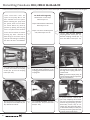
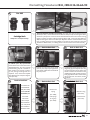
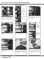
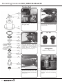
1
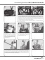
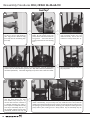
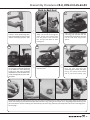
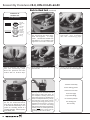
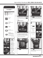
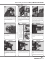
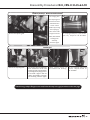
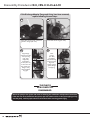
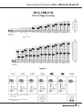
GRUNDFOS
CR SERVICE MANUAL
CR-H, CRN-H
32•45•64•90
Dismantling &
Reassembly
CONTENTS
Dismantling Procedures................................................... Page 2
When Should A Part Be Replaced ?...............................Page 12
Reassembly Procedures ................................................. Page 13
Setting The Coupling Height ..........................................Page 24
Order of Stage Assembly - CR-H, CRN-H 32.....................Page 27
Order of Stage Assembly - CR-H, CRN-H 45 ...............Page 28
Order of Stage Assembly - CR-H, CRN-H 64 ...............Page 29
Order of Stage Assembly - CR-H, CRN-H 90.....................Page 30
TORQUES
Position
Number
7a
Screw for Guard .......................................... 6 ft.-lbs./8 Nm
9
Coupling Screws ..................................... 63 ft.-lbs./85 Nm
26b
Allen Screw for Strap ............................ 11 ft.-lbs./15 Nm
28
Allen Screw Motor
Stool to Pump Head .............................. 46 ft.-lbs./62 Nm
28a
Allen Screw for Motor
1/2" x 13 UNC, 3-40 HP ........................ 30 ft.-lbs./40 Nm
5/8" x 11 UNC, 50-60 HP...................... 59 ft.-lbs./80 Nm
28g
Allen Screw for Foot/Base ................... 15 ft.-lbs./20 Nm
31
Allen Screw for Bottom
Stationary Bearing...................................... 6 ft.-lbs./8 Nm
35
Allen Screw for Discharge Flange...... 15 ft.-lbs./20 Nm
36
Staybolt Nut ..........................................74 ft.-lbs./100 Nm
48
Split Cone Nut ......................................... 52 ft.-lbs./70 Nm
56 c/e Allen Screw for Sleeve Flange
CR-H, CRN-H32, M12 ............................. 55 ft.-lbs./75 Nm
CR-H, CRN-H 45/64/90, M16 ............74 ft.-lbs./100 Nm
58a &
58d
Allen Screw Seal Carrier ....................... 46 ft.-lbs./62 Nm
67
Allen Screw for Shaft Bearing............. 23 ft.-lbs./31 Nm
113
Allen Set Screw for Shaft Seal ................. 6 ft.-lbs./8 Nm
Dismantling Procedures CR-H, CRN-H 32•45•64•90
In the instructions below, the numbers in parenthesis (7) indicate the position number of that part as it is shown on the Parts List and Kits diagram.
1
These instruc tions cover the
For shaft seal change only
repair of the pump after it has
Standard unit or a Cool Top®,
been isolated from the system.
follow steps 1 to 7.
Before removing the pump from
the system, make sure all valves
Pumps built with Back-to-Back seals,
are closed. Relieve any built-up
follow steps 1 to 10.
pressure by opening the vent plug
screw. The power source should be
Pumps built with Tandem/Quench
turned off and locked out before
seals, follow steps 25 to 39.
starting any work.
Removal of
field wiring to the motor may be
required. Color coding or numbering
Lo o s e n , b u t d o n o t r e m ov e ,
Coupling Guard Screws (Pos. 7a).
Remove Coupling Guards (Pos. 7)
from the Motor Stool (Pos. 1a).
the wires will aid in reinstallation.
2
3
4
Use an Allen wrench with an 8 mm tip
to loosen and remove the Coupling
Screws (Pos. 9) from the Coupling
Halves (Pos. 10a).
To remove the coupling halves, insert
a flat/slot blade screwdriver in the
coupling gap and twist to free the first
coupling half.
To free/remove the remaining coupling
half nearest the motor shaft, strike
the edge of the coupling half with a
rubber mallet.
Note: If you have multiple pumps, do
not interchange coupling components,
they are a matched set.
5
Remove the 8 mm socket Allen Screws
(Pos. 58a) from the Seal Retainer (Pos.
58). Remove the retainer.
2
6
Loosen, but do not remove, the 3 mm
Set Screws (Pos. 113) from the Shaft
Seal (Pos. 105).
7
Use two flat/slot blade screwdrivers
to pry the seal loose. Slide the seal
(Pos. 105) completely off the shaft
(Pos. 51). For seal change on Standard
and Cool Top pumps only, go to the
Reassembly section, step 54. For
STACK® (Pos. 80) replacement, Backto-Back Inboard Seal (Pos. 105b) and
Cool Top® Connecting Pipe (Pos. 149)
removal, continue with step 9.
Dismantling Procedures CR-H, CRN-H 32•45•64•90
8
Pos. 105
Cartridge Seals
Will lift out as a complete assembly.
9
To remove the motor stool (Pos. 1a) and motor: If needed, place a block under the Support
Bracket (Pos. 90c). Loosen and remove the Allen Screws (Pos. 28) connecting the motor
stool to the pump head. Leave the motor stool attached to the motor and/or bearing
flange to protect the motor shaft and bearing flange shaft. Loosen the Slide Rail (Pos.
90d) connecting the motor to the Base (Pos. 90), then slide the motor backward on the
base. If sliding provisions are not available on the base or when working on Cool-Top
and Back-to-Back models, use a lifting device to lift and remove the motor assembly
10
11
All models requiring full dismantling
for STACK® (Pos. 80) replacement:
Loosen but do not remove the 24 mm
Staybolt Nuts (Pos. 36). Then, proceed
to Dismantling, step 40. For Back-toBack inboard seal change, continue
by first placing blocking under the
staybolts. Then, remove the Staybolt
Nuts, Washers (Pos. 66a) and Support
Plate (Pos. 90c).
Remove the outermost Pump Head
(Pos. 2b). This may require light blows
with rubber mallet to the underside of
the pump head.
To remove the Outer Sleeve (Pos. 55a),
diagonally grip the Staybolts (Pos. 26).
Use your thumbs to press against the
sleeve to release the sleeve from the
middle pump head. If it does not move
freely, light blows with a rubber mallet
may be required. Once loose, remove
the sleeve.
13
14
15
Back-to-Back Seal
Back-to-Back Seal
Back-to-Back Seal
12
Back-to-Back Seal
Back-to-Back Seal
To remove the
Inboard Shaft
Seal (Pos. 105b)
Remove the
loosen, but do
Spring
Remove O-ring
not remove, the
(Pos. 108b),
(Pos. 107b),
two 3 mm
and Spring/
and Seal Driver
Set screws
O-ring Cup
(Pos. 111b).
(Pos. 113a) in
(Pos. 106b).
the Seal Driver
( Pos. 112). Slide
the seal driver
off of the shaft.
3
Dismantling Procedures CR-H, CRN-H 32•45•64•90
Back-to-Back Seal (continued)
16
18
17
Slide the
threaded seal
retainer off the
shaft. Next, slide
the Retaining
Washer
Remove the Rotating Seal Face
(Pos. 104b). Then, use adjustable
pliers or a 53 mm (2-1/8 in.) wrench
to remove the Threaded Seal Retainer
(Pos. 148).
19
(Pos. 59e) off
the shaft.
20
Using a small flat tip screwdriver, pry/
loosen the stationary seal from the
Connecting Pipe (Pos. 149). Slide the
seal off the shaft.
21
Loosen and
remove the
8 mm hex socket
Retainer Screws
(Pos. 58d).
Slide/remove the middle pump head
(Pos. 20).
22
Remove the Connec ting Pipe
(Pos. 149) and the innermost Pump
Head (Pos. 2).
4
Remove
the Connecting
Pipe Retainer
(Pos. 58c).
Remove the Spacing Ring (pos. 116).
23
Place the connecting pipe into one
of the pump heads. Use 00SV2128
and a rubber mallet to drive out the
Retainer Ring (Pos. 47h) and Bushings
(Pos. 47g).
24
Remove the O-rings (Pos. 109a and
109b). For reassembly of the seal and
connecting pipe, go to the Reassembly
section, step 17. To continue
disassembly, proceed to step 40.
Dismantling Procedures CR-H, CRN-H 32•45•64•90
Tandem Seal
25
Loosen the top
26
27
Coupling Guard
Screw (Pos. 7a),
but do not fully
remove. Loosen
and fully remove
the lower screw.
Tilt and slide
t h e Co u p l i n g
Remove system flush piping.
Guards (Pos. 7)
off of the system
Use an Allen wrench with an 8 mm tip
to loosen and remove the Coupling
Screws (Pos. 9) from the Coupling
Halves (Pos. 10a).
flush piping.
28
To remove the coupling halves, insert
a flat/slot blade screwdriver in the
coupling gap and twist to free the
first coupling half.
29
To free/remove the remaining
coupling half, strike the upper edge
of the coupling half with a rubber
mallet. Note: If you have multiple
pumps, do not interchange coupling
components, they are a matched set.
30
If the motor needs to be removed to
change the seals, remove the motor
to pump Bolts (Pos. 28a). Remove
motor off of Motor Stool (Pos. 1a).
31
32
33
Loosen, but do not remove, the
3 mm Set Screws (Pos. 113) from
the Tandem Shaft Seal (Pos. 105c).
Loosen and remove the 8 mm hex
socket Allen Screws (Pos. 58a) holding
the seal housing.
Use two flat/slot blade screwdrivers
to pry the seal loose. Slide the Seal
(Pos. 105c) completely off of the Shaft
(Pos. 51). Once removed, fully unscrew
the set screws (Pos. 113) and 105c
can be completely disassembled, see
exploded view on page 6.
5
Dismantling Procedures CR-H, CRN-H 32•45•64•90
Tandem Seal (continued)
34
35
112a
Seal Driver
Ring
113
Set
Screw
Remove the Tandem Seal Housing
O-ring (Pos. 109c).
Loosen, but do not remove, the 3 mm
Set Screws (Pos. 113) from the Shaft
Seal (Pos. 105).
77a
Seal
Housing
109c
O-ring for
Seal Housing
36
37
Pos. 105
102
Upper
O-ring
103
Stationary
Seal Face
The tapered face
should point
downward
through the
driver 111 and
press against the
O-ring 107).
104
Rotating
Seal Face
111
Floating
Seal Driver
Use two flat/slot blade screwdrivers
to pry the seal loose. Lift the seal
completely off the shaft. For seal
change only, go to the Reassembly
section, step 54. To continue
disassembly, proceed to step 38.
Cartridge Seals
107
O-ring
Will lift out as a complete assembly.
106
Cup for O-ring
and spring
108
Spring
38
39
112
Seal Driver
with Sleeve
110b
O-ring
Loosen and remove the 8 mm
hex socket Allen Screws (Pos. 28)
connecting the motor stool to Pump
Head (Pos. 2).
6
Loosen (but do not remove) the 24 mm
Staybolt Nuts (Pos. 36) and Washers
(Pos. 66a). Proceed to Dismantling,
step 40.
Dismantling Procedures CR-H, CRN-H 32•45•64•90
40
Loosen and remove all the Sleeve
Flange Nuts (Pos. 56e), Allen Screws
(Pos. 56c), and Washers (Pos. 56d)
from the Sleeve Flange (Pos. 55b).
43
41
42
Remove the plastic plugs from the
threaded jacking holes. Next, use two of
the sleeve flange allen screws and place
into the threaded holes of the sleeve
flange. Tightened diagonally, this will
force the cartridge assembly (Pos. 80a)
away from the Suction/Discharge Base
(Pos. 6). Warning: Do not allow the
cartridge assembly to fall.
To remove the cartridge assembly
from the Suction/Discharge Base,
grab the two top staybolts and slide
outward (some rocking movement
may be required). Warning: Cartridge
assemblies are heavy - a lifting device
may be required.
44
45
Cool-Top®
Cool-Top®
Move the cartridge assembly to a
workbench. Lay horizontal, then finish
removing the Staybolt Nuts (Pos. 36),
Washers (Pos. 66a), and Support Plate
(Pos. 90c). For Standard units, skip to
step 53. For Cool Top®, continue with
step 44.
Remove the outermost Pump Head
(Pos. 2b), Outer Sleeve (Pos. 55a) and
middle Pump Head (Pos. 2c) as a
complete assembly if it has not leaked,
then skip to step 48. If the assembly
has leaked, follow steps 45 to 47.
Remove the outermost pump head.
This may require light blows with
rubber mallet to the underside of the
pump head.
46
47
48
Cool-Top®
To remove the outer sleeve, diagonally
grip the Staybolts (Pos. 26). Using your
thumbs, press against the sleeve to
release the sleeve from the middle pump
head. If it does not move freely, light
blows with a rubber mallet might be
required. Once loose, slide the sleeve off.
Cool-Top®
Slide/remove the middle pump head
(Pos. 2c).
Cool-Top®
Remove the Spacing Ring (Pos. 116).
7
Dismantling Procedures CR-H, CRN-H 32•45•64•90
49
Cool-Top®
50
Cool-Top®
51
Cool-Top®
Loosen and
remove the 8
mm hex socket
Retainer Screws
(Pos. 58d).
Remove the
Connecting Pipe
Retainer
(Pos. 58c).
52
Cool-Top®
Remove the Connecting Pipe
(Pos. 149).
Place the connecting pipe into one of
the pump heads. Use 00SV2128 and a
rubber mallet to drive out the Retainer
Ring (Pos. 47h) and Bushings (Pos. 47g).
54
53
ALL UNITS
Remove the O-rings (Pos. 109a
and 109b). For reassembly of
the connecting pipe go to the
Reassembly section, step 18. To
continue disassembly, proceed to
step 53.
Remove Pump Head (Pos. 2) by
pushing away from sleeve (this may
require light tapping with a rubber
mallet to the underside of the pump
head to loosen). Once pump head
is loose, slide away from cartridge
assembly.
Remove the Stack (Pos. 80) from the
remainder of the assembly.
For STACK dismantling, go to step 59.
End of Cool Top specific instructions.
55
To remove outer sleeve (Pos. 55), grip staybolts diagonally. Using your thumbs, press
against sleeve to release the sleeve from the sleeve flange (light blows with a rubber
mallet may be required). Once the sleeve is loose, slide/remove it.
8
56
Using a small screwdriver, remove
Sleeve O-rings (Pos. 37) from the pump
head and the sleeve flange.
Dismantling Procedures CR-H, CRN-H 32•45•64•90
57
Remove the four STACK Compression
Spacers (Pos. 60).
58
To remove the Bottom Bearing (Pos. 6g), loosen and remove the 5 mm Hex Socket Allen
Screw (Pos. 31) and Washer (Pos. 32) from the Sleeve Flange (Pos. 55b). Using the Bearing
Puller (00SV0002) and M8 x 50 mm Allen Screw (00ID6595), insert the bearing puller
along with the allen screw at an angle until it passes through the bearing. Once the
bearing puller is under the bearing's lower edge, turn the 6 mm hex socket allen screw
until the bearing has been pryed out of the housing.
For STACK replacement, proceed to Reassembly, step 11. For STACK Dismantling,
continue with step 59.
59
Fit assembly/disassembly tool
(00SV0003) to Stack. The tool
consists of different size spacing
plates. Select the plate which fits
securely to the Stack Interface (Pos.
44). Place holding pin into the
disassembly hole.
60
Loosen the chamber straps, remove
6 mm hex socket Allen Screw
(Pos. 26b), Washer (Pos. 26c), and
Chamber Straps (Pos. 26a).
62
Loosen Split Cone Nut (Pos. 48) approximately two to three full turns with split cone
nut wrench (00SV0004). Flip tool over and give a sharp blow directly down against
the split cone nut. This will loosen the Split Cone (Pos. 49b) and allow the Impeller
(Pos. 49a) to be lifted off the shaft. Lift off Chambers (Pos. 4 & 4a). Repeat this process
until all impellers are removed from Shaft (Pos. 51).
61
Remove the Upper Chamber (Pos. 3).
63
Remove Base Interface (Pos. 44).
9
Dismantling Procedures CR-H, CRN-H 32•45•64•90
64
To remove the shaft from the
assembly/disassembly tool, remove
the holding pin from the shaft and
lift shaft out of tool.
After inspecting the parts, if further
disassembly is required, proceed to
the next steps.
66
Depending on wear, the Neck Ring
(Pos. 45), Retainer (Pos. 65), and Holder
(Pos. 45a) may need to be removed.
Using a flat bar, pry these components
out of the chambers and base
interface as a complete assembly.
69
Punch
To remove the Chamber Bearing
(Pos. 47), Bearing Sleeve (Pos. 47c),
and Bearing Lock Ring (Pos. 47d),
place chamber upward using the
punch (00SV0015). Drive the bearing
downward.
10
65
Remove bearing from shaft. Remove
6 mm hex socket Allen Screw (Pos. 67),
Locking Washer (Pos. 66b), Washer
(Pos. 66), and Journal Bearing (Pos.
47b). Loosening the allen screw may
require use of the holding pin as a
countering device so the shaft does
not spin.
67
If wear or damage is minor, the
neck ring may be replaced using a
screwdriver to twist and pry out the
retainer.
70
If the Impeller Wear Ring (Pos. 49c) is
worn and the split cone nut/impeller hub
threads are not damaged, the wear ring
may be removed using the appropriate
support tool,
•CR-H, CRN-H 32 00SV0043
•CR-H, CRN-H 45 00SV0044
•CR-H, CRN-H 64 00SV0045
•CR-H, CRN-H 90 00SV0046
along with the wear ring puller
(00SV0239) used to pry off the wear ring.
If the threads of the impeller hub are
damaged, a new impeller will be required.
68
Lift out the Neck ring (Pos. 45).
Dismantling Procedures CR-H, CRN-H 32•45•64•90
If the Discharge Adaptor Flange (12a) has leaked, the O-ring may need replacement.
To remove, follow the next steps after removing the system discharge piping.
71
Push the Flange Ring (Pos. 201) down,
use a screwdriver to remove the
Retaining Ring (Pos. 203), then remove
the flange ring.
72
73
Remove the Flange Allen Screws
(Pos. 35).
Remove the O-ring (Pos. 39b).
THE PUMP IS
NOW COMPLETELY
DISASSEMBLED.
11
Dismantling Procedures CR-H, CRN-H 32•45•64•90
When Should A Part Be Replaced?
Part
Position(s)
Pump Head
2
Suction/Discharge
6
Base
}
Minimum Operating Condition
Excessive pitting of these castings could cause leaks. Rusted castings should have all seating areas cleaned to ensure proper
seating of O-rings.
Chambers
3, 4a, 4
O-rings
37, 38, 38a, 100
Should be soft and pliable with no visible scars. Since they
are easily damaged and fairly inexpensive, it is recommended
they be replaced whenever the pump is disassembled.
Neck Ring
45
Should be free of visible wear on the inside edges.
Inside diameter for:
CR-H, CRN-H 32 = 66.2 mm
CR-H, CRN-H 45 = 73.9 mm
CR-H, CRN-H 64 = 86.3 mm
CR-H, CRN-H 90 = 93.8 mm
Bearing Ring
47a
The diameter size difference between the Bearing Ring (Pos. 47a) and the Bearing (47) fixed inside the intermediate chambers should be no greater than 0.4 mm.
Bushing and Bearings
6g, 47, 47b, 47c
Wear to the inner surface on the chamber bushings (Pos. 47c) fixed inside the intermediate chambers should
be no greater than 0.6 mm. The wear to the bottom
bearings, Pos. 6g and 47b, should be no greater than .4 mm.
Impellers
49 (a, d, e & i)
Should be free from physical markings except for the guide
vane welds. Any additional identations may result from:
(2) Improper coupling height - If the coupling is not set to the
proper height (see Reassembly procedures: Back-to-Back,
steps 43, 74 to 80; Standard & Cool Top, steps 74 to 80;
Tandem/Flush Seal, steps 56, 72, 73 78 to 80) the impellers are
not suspended as they should be, but instead they rub against
the chambers, either above or below, causing contact wear.
(3) Worn groove to Impeller Wear Ring (Pos. 49c) from system
sediments. Wear rings should be replaced, or impeller complete if
threaded area for split cone nut is damaged.
Shaft
51
Should show no signs of gouging or wear throughout its total length. If reusing the shaft, use a light grit emery cloth to smooth
away sharp edges made by the shaft seal set screws.
Stack Compression Spacer
60
Should always be replaced.
105 (a, b & c)
Should seal without leakage
Shaft Seal Cartridge Cpl.
Same as for impellers.
(1) Cavitation - the implosion of vapor "bubbles" within the impeller stack. Make sure the Net Positive Suction Head
Available for the pump meets the minimum Net Positive
Suction Head Required for the pump when runnning at the
required flow.
Refer to the Parts List and Kits section for a list of material numbers and spare part kits.
12
Reassembly Procedures CR-H, CRN-H 32•45•64•90
1
2
To reinstall the Neck Ring (Pos. 45),
the Neck Ring Retainer (Pos. 65), or
complete Neck Ring Assembly (Pos.
45a), place these components into
the Chamber (Pos. 4 or 4a) or Base
Interface (Pos. 44). Position the
appropriate neck ring punch
•CR-H, CRN-H 32 00SV0025 •CR-H, CRN-H 45 00SV0027
•CR-H, CRN-H 64 00SV0028
•CR-H, CRN-H 90 00SV0029
Punch
To reinstall the Chamber Bearing Ring
(Pos. 47), or Bearing Sleeve (Pos. 47c),
and Bearing Lock Ring (Pos. 47d or 47e),
place the chamber in a downward
position. Depending on the type of
Chamber used (Pos. 3, 4a, or 4), place
the appropriate components (Pos.
47 or 47c) and (Pos. 47d or 47e) onto
the chamber. Position the reduced
diameter end of the punch through
the components. Use a rubber mallet
to drive in place.
3
Before reusing the Shaft (Pos. 51), use an
emery tool to smooth away shaft seal set
screw marks and make sure the main shaft
area is not worn. If the Journal Bearing (Pos.
47b) was removed, replace the journal bearing. Add the Clamping Washer (Pos. 66), and
two Locking Washers (Pos. 66b). Loosely
thread the 6mm Allen Screw (Pos. 67) onto
the shaft. To ensure journal bearing and
clamp washer alignment, slide the Bottom
Bearing (Pos. 6g) over these items. Place the
holding pin through the shaft to prevent
it from spinning while the allen screw is
tightened to a torque of 23 ft.-lbs./31Nm.
Remove the hold pin and the bottom
bearing 6g after torque value is achieved.
6
After pressing on a new Wear Ring
(Pos. 49c), or if using a new Impeller
(Pos. 49d, e, or i), place the complete
impeller over the shaft and seat into the
interface assembly. Slide the Split Cone
(Pos. 49b) down the shaft and into the
recessed area of the impeller hub. Use
the split cone nut tool (00SV0004) in the
inverted direction and firmly drive
split cone into the impeller. While
performing this function, care must
be taken to avoid damaging the
threaded hub area of the impeller.
onto the components to be inserted
into the chamber or base interface.
Using a rubber mallet, drive these
components firmly in place.
4
Fit the shaft into the assembly/
disassembly fixture (00SV0003).
Make sure the holding pin is inserted
into the assembly hole. Refer to
the diagrams on pages 27-30 for
the appropriate staging sequence.
5
Fit the Base Interface Assembly
(Pos. 44 or 44a) onto the assembly/
disassembly fixture. Be sure to
use the appropriate spacing plate
that fits snugly to the bottom
of the base interface. Using the
incorrect spacing plate can lead to
rotation and end play* problems.
* End play is shaft travel (up and down) through
the chambers.
7
Place Gardolube (00SV9995) or
equivalent FDA approved non-toxic
lubricant on the threaded area of the
hub. Thread the Split Cone Nut
(Pos. 48) onto the impeller. Using
the split cone nut tool (00SV0004),
Adapter (00SV0403), and Torque
Wrench (00SV0269), torque the
split cone nut to 52 ft.-lbs./70 Nm.
13
Reassembly Procedures CR-H, CRN-H 32•45•64•90
9
8
10
Remove the holding pin from the
Refer to the diagrams on pages
assembly/dismantling fixture.
27-30 for the appropriate staging
Lift the STACK® (Pos. 80) out of
sequence for your particular
the fixture. Lay the stack on a flat
model pump.
chamber has been installed,
continue with step 9.
11
To install the Bottom Bearing (Pos. 6g)
into the Sleeve Flange (Pos. 55b), place
the bearing into the hole provided in
the flange. Ensure the recessed area
of the bearng is located where the
hole for the allen screw is machined
in the flange.
14
Use the appropriate sleeve flange O-ring
material for the application. Standard
units: EPDM or FKM (Pos.37). Exotic and/
or fluid with temperatures over 250° F,
use FXM or FFKM (Pos.37a). Place the
sleeve o-rings into the recessed groove
in the Pump Head (Pos.2, 2b & 2c) and
the sleeve flange. In Cool Top® equipped
pumps, the lower hot section of the pump
(pump head [Pos.2] and the sleeve flange)
should have FXM or FFKM o-rings. For all
material types: never use oil or grease
on the o-rings; lubricate the o-rings with
Rocol (00RM2924) or Dow Corning 111.
14
surface and check the rotation and
Once the last
Hook the Chamber Straps (Pos. 26a)
through the Base Interface (Pos. 44).
Position top end of straps into relieved
area of the Top Chamber (Pos. 3). Place
the Washer (Pos. 26c) and 6 mm hex
socket Allen Screws (Pos. 26b) loosely
threaded into the straps. Allen screws
must be pre-lubricated with Gardolube.
Torque evenly to 11 ft.-lbs./15 Nm.
end play*. Movement should be
free and without binding.
*End play is shaft travel (up and down)
through the chambers.
12
13
Use the Bearing Punch (00SV0015)
and a rubber mallet to gently drive the
bearing into place.
Place the Washer (Pos. 32) and 5 mm
hex socket Allen Screw (Pos. 31) into
the suction/discharge base. Tighten
down against the bearing to hold
in place. Torque to 6 ft.-lbs./8 Nm.
15
16
Place the STACK® Assembly (Pos. 80)
into the sleeve flange. Rotate straps
so they are centered between the
Staybolts (Pos. 26). Support blocks
(like 2x4 material) may need to be
used under the sleeve flange to
prevent toppling.
Place Sleeve
(Pos. 55) into the
sleeve flange.
Line up venting
sticker with
flat surface of
sleeve flange.
This will ensure
the lubrication
hole is pointed
downward when
assembled.
Press sleeve
firmly in place.
This may require
gentle taps with
a rubber mallet.
Reassembly Procedures CR-H, CRN-H 32•45•64•90
17
Replace the four PTFE Stack Compression Spacers (Pos. 60) into the Pump Head (Pos. 2) which will seat against the stack. Lubricate the
inner bore of the pump head, or all pump heads for Cool Top® or Back-to-Back seal equipped pumps, with Rocol (00RM 2924) or Dow
Corning 111. For Standard, Cool Top® and Tandem equipped pumps, position and lower the completed pump head over the Staybolts
(Pos. 26). Make sure the vent plug (Pos. 18) is located in line with the vent sticker and the flat surface of the sleeve flange. Use a rubber
mallet to firmly seat the pump head.
For Standard and Tandem equipped seal pumps, skip to reassembly step 46.
For Cool Top® units, continue with Reassembly steps 18 to 24.
For Back-to-Back units, skip to Reassembly steps 25 to 46 .
15
Reassembly Procedures CR-H, CRN-H 32•45•64•90
Cool-Top®
18
Use 00SV2128 and a rubber mallet
to drive in three new Bushings
(Pos. 47g) and the Retainer Ring
(Pos. 47h) into the Connecting Pipe
(Pos. 149).
19
Replace the O-rings (Pos. 109a &
109b). Do not roll the O-ring into
place; stretch and release them into
the grooves. Then lubricate the
O-rings with Rocol or Dow Corning
111.
Lower and seat the Retainer (Pos. 58c) for the connecting pipe. Lubricate the threads
of the 8 mm hex socket Retaining Screws (Pos. 58d) with Gardolube (00SV9995) or
Thread-Eze (96611372). Install and diagonally torque the screws to 46ft.-lbs./62Nm.
If the uppermost Pump Head
(Pos. 2b), upper Sleeve (Pos. 55a)
and middle Pump Head (Pos. 2c)
did not leak and were removed as
a complete assembly, then lower it
back in place as a complete assembly
and skip to reassembly step 46. If
the assembly leaked and was fully
dismantled, continue with step 24.
16
Slide the completed connecting
pipe assembly down over the
shaft and firmly seat it into the
lowermost Pump Head (Pos. 2).
22
21
23
20
Place the Spacing Ring (Pos. 116) onto
the pump head.
24
O-rings of EPDM or FKM should have already been installed into the pump heads as
noted in Reassembly, step 14. If they were not, install them now. Then, lower the
middle pump head and carefully press it over the connecting pipe O-ring and seat it on
the spacing ring. Install the upper sleeve, and firmly press it in place. Put the uppermost
pump head in place, making sure it is firmly seated. Skip to reassembly step 46.
Reassembly Procedures CR-H, CRN-H 32•45•64•90
Back-to-Back Seal
25
Use 00SV2128 and a rubber mallet
to drive in three new Bushings (Pos.
47g) and the Retainer Ring (Pos.47h)
into the Connecting Pipe (Pos. 149).
28
Lower the Retainer (Pos. 58c) over the
connecting pipe. Lubricate the threads
of the 8mm hex socket Retaining
Screws (Pos. 58d) with Gardolube
(00SV9995) or Thread-Eze (96611372).
Install and diagonally torque to 46ft.lbs./62Nm.
26
Replace the O-rings (Pos. 109a &
109b). Do not roll the O-ring into
place; stretch and release them
into the grooves. Then lubricate
the O-rings with Rocol or Dow
Corning 111.
29
Place the Spacing Ring (Pos. 116) onto
the pump head.
27
Place and fully seat the complete
connecting pipe assembly into the
lowermost Pump Head (Pos. 2), which
has the PTFE stack compression
spacers.
30
Lower the middle Pump Head
( Po s . 2 c ) o v e r a n d p a s t t h e
connecting pipe threads and upper
O-ring. The pump head should
rest on top of the spacing ring.
31
Assemble the stationary seal by placing the O-ring (Pos. 102) over the Retainer (Pos. 103a). Place the O-ring (Pos. 102a) into the retainer
recess. Lubricate/spray a 5% solution of soapy water onto the O-ring resting in the retainer recess. Align edges of the Stationary Seal
(Pos. 103) with the retainer and firmly press the stationary seal into O-ring. Stationary seal components can be seen in the diagram on
the next page.
17
Reassembly Procedures CR-H, CRN-H 32•45•64•90
Back-to-Back Seal (continued)
COMPONENTS OF
STATIONARY SEAL
32
33
Lubricate the inner surface of
the connecting pipe with Rocol,
Dow Corning 111, or soapy
water. Lubricate the threads with
Gardolube or an equivalent FDA
approved non-toxic lubricant.
Lower and press the completed
stationary seal assembly
into the connecting pipe.
"N" PUMPS AND MODEL B
Side View
Pos. 103
Upper Seal
Ring
Pos. 102a
O-Ring
Side View
Pos. 103a
Retainer
For Upper
Seal Ring
Pos. 102
O-Ring
34
35
Press the stationary seal assembly
into the connecting pipe.
Clean the polished seal face
surface with an alcohol wipe.
Place the Retaining Washer (Pos. 59a)
onto the seal.
37
38
36
Loosely thread the Securing Nut
(Pos. 148) onto the connecting pipe.
The order of assembly
for the rotating portion
Use special tool 00SV7902 to tighten
the nut. The underlined text for
steps 38 to 45 depends if the unit
is still attached horizontally in the
system or is standing vertical as a
cartridge assembly. If vertical, lower;
if horizontal, slide.
18
When reusing an existing shaft, first
clean any set screw marks off the shaft
with a light grit emery cloth. Next, lift
the complete assembly (lowermost
pump head, spacing ring, middle pump
head, and complete stationary seal) by
the lowermost pump head. Position
the Priming Vent Plug (Pos. 18) on the
lowermost pump head so it is pointing
upward or is in line with the venting
label and flat surface of the sleeve flange.
Carefully lower the assembly down the
shaft and staybolts. Firmly seat the
assembly in place onto the sleeve.
of the seal can be seen
on the next page.
To prevent leakage,
it is critical to position
the rotating seal
face correctly.
Reassembly Procedures CR-H, CRN-H 32•45•64•90
Back-to-Back Seal (continued)
COMPONENTS OF ROTATING SEAL
39
40
LOWER COMPONENTS OF
SEAL ASSEMBLY
Pos. 112
Seal Driver with set
screws, Pos. 113
Pos. 108
Spring
With the tapered edge facing
u p w a rd / o u t w a rd , s l i d e /l o w e r
the Rotating Seal Face (Pos. 104)
down onto the stationary seal face.
Pos. 112
Low er Seal D river
Pos. 108
Shaft Seal Spring
Note:
Upward, if vertical
Outward, if horizontal
Pos. 106
Cup for O-ring and
Spring
41
Slide/lower the Floating Seal Driver
(Pos. 111) until it fully engages the
rotating seal face. Ensure the taper of
the rotating seal protrudes through
driver.
42
Pos. 106
C up for Spring
Slide/lower the
Pos. 107
O-Ring
Cup (Pos. 106)
Pos. 107
O -R ing
over the O-ring.
Pos. 111
U pper Seal D river
Pos. 104
Low er Seal R ing
(Tapered end
pointing dow nw ard)
43
Lower the
Pos. 111
Floating Seal Driver
Pos. 104
Rotating Seal Face
(The tapered face should point
outward/upward through the
driver 111 and press against
the O-ring 107).
Slide/lower the
Driver (Pos. 112)
with set screws
(Pos. 113).
Driving tabs
should pass and
engage each
other. With the
shaft and the
seal drivers
pushed down/
inward as far as
possible, tighten
the 3mm Set
Screws
(Pos. 113) to
10ft.-lbs./13Nm.
Spring
Lubricate the inner surface of the
O-ring (Pos. 107) with Rocol, Dow
Corning 111, or soapy water. Slide the
O-ring down the shaft until it contacts
both the driver and the protruding
surface of rotating seal face.
44
Slide/lower and seat the upper Sleeve
(Pos. 55a) into the middle pump head.
(Pos. 108) until
it fits over the
cup.
45
Slide/lower and firmly seat the
uppermost/outermost Pump Head
(Pos. 2b) onto the upper sleeve.
Proceed to step 46.
19
Reassembly Procedures CR-H, CRN-H 32•45•64•90
46
Opposite the vent plug, place the Cartridge Support Foot (Pos. 90c)
over the staybolts. The angle should be facing downward toward the
sleeve flange. Place the Washers (Pos. 66a) over the staybolts opposite
the support foot. Lubricate the threads on all of the staybolts with
Gardolube or Thread-Eze. Loosely tighten the Staybolts Nuts (Pos. 36)
do not torque at this time, this will be done in step 52. The Cartridge
Assembly (Pos. 80a) is now ready to take back to where the Suction
Discharge Base (Pos. 6) is located.
47
If the old O-ring (Pos. 72a) was not removed earlier, remove now and clean the groove in
Suction/Discharge Base (Pos. 6). Next, in four equal spaced areas, place a liberal amount
of Dow Corning 111 or Rocol into the groove. Fit the new O-ring into the groove, ensuring
it is fully seated and does not move out of position.
49
Before installing the Screws (Pos. 56c), Washers (Pos. 56d), and Nuts (Pos. 56e) into the
Sleeve Flange (Pos. 55b) ensure the flange is fully seated; there should not be any gap
between the flange and the suction discharge base. If there is a gap, either the o-ring
from step 47 has moved out of place and is pinched, or the flange is not properly engaged
into the machined recess/register in the base (see diagram at the right). Repair before
proceeding. If properly seated, apply Gardolube or Thread-eze to the screws, then torque
diagonally as follows: CR-H 32: 55 ft.-lbs. / 75 Nm • CR-H 45/64/90: 74 ft.-lbs. / 100 Nm
20
48
Align the cartridge and slide it into the
suction/discharge base, making sure
that the O-ring from step 47 is still
in place. Also, make sure the sleeve
flange flat surface, venting label, and
vent plug are facing upward.
Reassembly Procedures CR-H, CRN-H 32•45•64•90
51
50
If the motor was removed during
disassembly, reattach the motor.
Lubricate the threads of the Motor
Bolts (Pos. 28a) and then tighten the
bolts diagonally to:
52
Slide the motor and Motor Stool (Pos.
1a) assembly down to the Pump Head
(Pos. 2). Slightly liftng the cartridge may
be required to allow the motor stool
register to fully seat to the pump head.
Lubricate the threads on the 8 mm
hex socket Retaining Screws (Pos.
28) with Gardolube or Thread-Eze.
Install and hand-tighten all four Allen
Screws connecting the motor stool to
pump head. If the holes do not line
up, grab and twist the cartridge by the
staybolts, then diagonally torque the
allen screws to 46 ft.-lbs./62 Nm.
53
54
30 ft.-lbs./41 Nm for 1/2" x 13 UNC, 3-40 HP
59 ft.-lbs./80 Nm for 5/8" x 11 UNC, 50-60 HP
55
Tighten the Slide Rail Screws
(Pos. 90d) connecting the motor to
the base
plate.
When reusing an existing shaft, if the
shaft has not already been cleaned,
first clean away any set screw marks
off of the shaft with a light grit emery
cloth. Then, wipe away dust before
proceeding to the next step.
56
57
Tandem Seal
Push the shaft all the way in, then
evenly tighten and torque the three
3 mm set screws to 6 ft.-lbs./8 Nm.
Torque the Staybolt Nuts diagonally to
74 ft.-lbs./100 Nm.
Tandem Seal
From the Seal Kit, install the desired
EPDM or FKM O-ring (Pos. 110b) into
the groove at the bottom of the seal
driver with sleeve (Pos. 112).
Lubricate the inner surface of the lower
O-ring of the Shaft Seal (Pos. 105) with
Rocol, Dow Corning 111, or soapy water.
Slide the seal down the shaft by pushing
against the drive collar of the seal. Seat
the seal firmly in place. For Tandem
Seal equipped pump only, continue
with step 56. All other pump types:
Standard, Cool top, and Back-to-Back
units, skip to step 74.
58
Tandem Seal
Slide the Spring (Pos. 108) over the
sleeve.
21
Reassembly Procedures CR-H, CRN-H 32•45•64•90
Tandem Seal
60
59
Fit the cup for O-ring and Spring (Pos.
106) onto the spring.
Complete 105c
Tandem Seal
Assembly
Exploded
View
61
Select the desired EPDM or FKM O-ring
(Pos. 107) and slide it down the seal
driver sleeve until it is seated into
the cup.
Fit the floating driver (Pos. 111)
onto the O-ring. Make sure the
tabs are facing downward and then
engage with the tags of lower driver.
62
112a
Seal Driver Ring
In the Exploded View,
113
Set Screw
the order of assembly
for the rotating portion
of the seal can be seen.
77a
Seal Housing
To prevent leakage,
it is critical to position
the rotating
109c
O-ring for Seal
Housing
Seal Face (Pos. 104)
102
Upper O-ring
correctly.
With the tapered face pointing
downward, install the Rotating Seal
(Pos. 104). Tapered face should pass
through the driver 111 and should
press against the O-ring (Pos. 107).
103
Stationary Seal Face
104
Rotating Seal Face
The tapered face
should point
downward
through the
driver 111 and
press against the
O-ring 107).
64
111
Floating Seal Driver
107
O-ring
106
Cup for O-ring
and spring
108
Spring
112
Seal Driver
with Sleeve
110b
O-ring
22
63
If it was not already done, remove the
Stationary Seal (Pos. 103) and O-ring
(Pos. 102). Use Punch, 00SV0015, and
a rubber mallet.
Place the desired EPDM or FKM
O-ring (Pos. 102) onto the new
Stationary Seal (Pos. 103).
Reassembly Procedures CR-H, CRN-H 32•45•64•90
Tandem Seal (continued)
66
65
Spray soapy water onto the o-ring
and seal the insert. Fully seat these
items into the Tandem Seal Housing
(Pos. 77a). Clean the polished surface
with an alcohol wipe/swab.
67
Place the rotating seal assembly
onto Punch 00SV0015. Before
lowering the tandem/flush seal
housing, make sure the tabs of the
drivers are positioned correct/engage
each other.
69
68
Tandem Seal
Hold this housing down. (If the set
screw holes are not fully accessible,
remove the housing and reposition
the driver tabs.) Install the Seal
Driver Ring (Pos. 112a). Turn the
3 mm set screws until they just
engage through the sleeve.
70
Tandem Seal
Apply Rocol or
Dow Corning
111 to the
groove in the
housing of the
Tandem Seal
(Pos. 105c).
Place the
Turn the Tandem/Flush Seal Assembly
(Pos. 105c) over and remove the
Punch, 00SV0015.
O-ring
(Pos. 109) into
the groove of
the tandem
Pushing against the drive collar, slide
the tandem seal assembly down the
shaft until it stops against the lower
shaft seal.
seal housing.
71
Tandem Seal
Lubricate the threads of the 8 mm
hex socket Retaining Screws (Pos. 58d)
with Gardolube or Thread-Eze. Install
and diagonally torque to 46 ft.-lbs./62
Nm.
72
Tandem Seal
Push down/inward on the shaft and
evenly tighten. Then, torque the three
3 mm set screws to 6 ft.-lbs./8 Nm.
73
Tandem Seal
Pull the shaft outward and place the
Adjust Fork/Spacing Tool, 985924,
between the housing and seal driver
ring.
Tandem Seal continues with step 78.
23
Reassembly Procedures CR-H, CRN-H 32•45•64•90
Standard, Cool Top®, & Back-to-Back Seal Units
74
Lower and seat the Retainer
(Pos. 58). Lubricate the threads of
the 8 mm hex socket Retaining
Screws (Pos. 58a) with Gardolube
or Thread-Eze. Install and diagonally
torque the screws to 46ft.-lbs./62Nm.
77
Push the shaft inward (for Back-to-Back
units, continue inward pressure as the
inboard seal spring tension may push the
shaft out). Evenly tighten, then torque the
three 3 mm set screws to 6 ft.-lbs./8Nm.
Standard, Cool Top®, & Back-to-Back Seal Units
To install the Coupling Halves (Pos.
10a), position the coupling half relief
area flushed with the top of the shaft
as shown in the diagram. Lubricate the
threads on the 8 mm hex socket Coupling
Screws (Pos. 9) with Gardolube or ThreadEze. Loosely thread the screws in place.
79
Torque the 8 mm hex socket coupling
screws to 63 ft.-lbs./85 Nm. This step
is the same for all pump types (in the
photo a tandem seal version is shown).
24
76
75
Correct
80
Make sure the gaps on both sides of
the coupling are even. Applies to all
pump types.
Pull the shaft outward and insert the
adjusting fork under the seal collar.
78
Tandem Seal Only
Place a second adjusting fork
on top of the seal collar. Install
the Coupling Halves (Pos. 10a).
Lubricate the threads on the
8 mm hex socket Coupling Screws
(Pos. 9) with Gardolube or Thread-Eze.
Loosely thread the screws in place.
Reassembly Procedures CR-H, CRN-H 32•45•64•90
Standard, Cool Top®, & Back-to-Back Seal Units
82
81
For storage, place
83
the adjusting fork
around one of the
seal holder allen
screws. Check
rotation by turning
the coupling by
hand. If the shaft
Remove the adjusting fork.
is tight or will not
rotate, disassemble
Fit Coupling Guard (Pos. 7) over screws
(Pos. 7a). Torque to 6 ft.-lbs./8Nm.
and begin the
assembly
procedure again.
Tandem Seal
85
84
Remove the adjusting forks
For storage, place the adjusting
forks around two of the seal
retaining screws. Check rotation
by turning the coupling by hand.
If the shaft is tight or will not
rotate, disassemble and begin
the assembly procedure again.
86
Install system piping to
the tandem seal housing.
87
Fit the coupling guard and
screws. Torque screws to
6 ft.-lbs./8Nm.
If the discharge adapter flange was removed, follow the steps in the gray boxed area on the next page.
25
Reassembly Procedures CR-H, CRN-H 32•45•64•90
If the Discharge Adaptor Flange and O-ring have been removed,
replace following the next steps:
89
90
Apply Dow Corning 111 or Rocol to
groove in Flange (Pos. 12a).
Place and seat O-ring (Pos. 39b).
91
92
Align flange
position to locate
1/4" Pipe Plug
(Pos. 23b).
Diagonally
torque Allen
Screws (Pos. 35)
to 15 ft.-lbs./20
Nm. Make sure
flange is fully
seated without
any gaps.
Place
Flange
(Pos. 201)
on adaptor.
Place Retaining
Ring (Pos. 203)
in groove.
Attach system
gasket, flange
and piping.
THE PUMP IS
NOW COMPLETELY
REASSEMBLED.
Return the pump to the system and install it following the Installation and Operation instructions.
If the unit was not removed from the system, open the isolation valves in the system piping to fully
vent the pump. Confirm proper electrical connections before restoring power supply.
26
Reassembly Procedures CR-H, CRN-H 32•45•64•90
CR-H, CRN-H 32
Order of Stage Assembly
Low NPSH
Combination
Replacement
Start for Low NPSH
order *
Low NPSH
Combination
Replacement
Legend
*Low NPSH units start with 2-1 and continue
to the 14 stage.
NOTE: Refer to Parts List for ALL position
descriptions.
27
Reassembly Procedures CR-H, CRN-H 32•45•64•90
CR-H, CRN-H 45
Order of Stage Assembly
Low NPSH
Combination
Replacement
Start for Low NPSH
order *
Low NPSH
Combination
Replacement
Legend
*Low NPSH units start with 2-1 and continue
to the 10 stage.
NOTE: Refer to Parts List for ALL position
descriptions.
28
Reassembly Procedures CR-H, CRN-H 32•45•64•90
CR-H, CRN-H 64
Order of Stage Assembly
Low NPSH
Combination
Replacement
Start for Low NPSH
order *
Low NPSH
Combination
Replacement
Legend
*Low NPSH units start with 2-1 and continue
to the 7-1 stage.
NOTE: Refer to Parts List for ALL position
descriptions.
29
Being responsible is our foundation
Thinking ahead makes it possible
Innovation is the essence
CR-H, CRN-H 90
Order of Stage Assembly
Low NPSH
Combination
Replacement
Start for Low NPSH
order *
Low NPSH
Combination
Replacement
Legend
*Low NPSH units start with 2-1 and continue
to the 6 stage.
NOTE: Refer to Parts List for ALL position
descriptions.
L-SM-DR-101 01/10
PRINTED IN USA
30
GRUNDFOS Pumps Corporation
17100 W. 118th Terrace
Olathe, Kansas 66062
Phone: 913.227.3400
Fax: 913.227.3500
www.grundfos.com
GRUNDFOS Canada, Inc.
2941 Brighton Road
Oakville, Ontario L6H 6C9 Canada
Phone: 905.829.9533
Fax: 905.829.9512
Bombas GRUNDFOS de Mexico S.A. de C.V.
Boulevard TLC No. 15
Parque Industrial Stiva Aeropuerto
Apodaca, N.L. Mexico 66600
Phone: 52.81.8144.4000
Fax: 52.81.8144.4010