1
FOREWORD
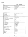
This service manual provides technical information on the 1980 models including its
features, differences from the 1979 models
and new service procedure.
Please read this manual thoroughly so that
you can have a good knowledge of the new
model and make best use of it in your sales
and after-service activities.
SERVICE DEPARTMENT
YAMAHA MOTOR CO,. LTD.
NOTE:
--~---
_
The Research and Engineering Departments
of Yamaha are continually striving to further
perfect all models. Improvements and
modifications are therefore inevitable.
In light of this fact, all specifications within
this manual are subject to change without
notice.
Particularly important information is distinguished in this manual by the following
notations:
NOTE:
A NOTE provides key information to make
procedures easier or cleaner.
CAUTION:
A CAUTION indicates special procedures
that must be followed to avoid change to the
machine.
WARNING:
A WARNING indicates special procedures
that must be followed to avoid injury to a
machine operator or person inspecting or repairing the machine.
·1980 ET250
CONTENTS
1. MODI·FICATIONS
A. ENGINE
8.
DRIVE
C. CHASSiS
,
D. ELECTRICAL.
2. SERVICE
A. NEW SERVICE PROCEDURE
B. MAINTENANCE INTERVALS
C. SPECiFiCATIONS
D. SPECIAL TOOLS
E.
WIRE ROUTING DIAGRAM
F.
WIRING DIAGRAM
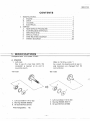
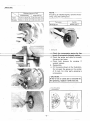
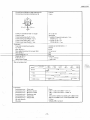
A. ENGINE
1. Left crank
Due to use of a new type clutch, the
crankshaft is tapered at its end to
mount the clutch.
..
...
,
,
,
,
3
4
6
7
7
10
12
17
19
20
(Refer to "8. Drive, clutch.")
As a result. the bearing and oil seal inside diameters are changed from 32
mmto 30 mm.
'79 model
'80 model
1. Left crank (8J2-11412-00l
2.' 8earing(93306-30617)
3. Oil seal (93102-30188)
1. Left crank (8F3-11412-00)
. 2. Bearing (93306-30605)
3. Oil seal (93102-32161)
Interchangeability:
,
No
-1
1980 ET250
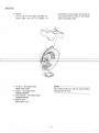
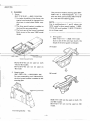
2. Starter
The air duct is no longer provided because there will be no problem of
overheating. Accordingly, the insert for
mounting of the air duct on the starter
case is no longer used.
1. Air duct ... No longer used
(8G5-15471-001
2. Screw ... No longer used
(98506-050081
3. Plain washer H' No longer used
(92906-05200)
4. Starter case
(8F3-15711-01 )
NOTE: - - - - - - - - - - - - , - - The 1979 model can also be used without
installing the air duct.
-2-
1980 ET250
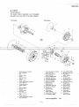
B. DRIVE
Primary sheave
For better clutch operation and increased
durability, the new clutch has been adopted.
'79 model
'80 model
2
1. Primary sheave cap complete
(8H7-17630-00l
2. Bolt
(90105-12009l
3. Washer
(90215-12084)
4. Washer
(90201-121911
5. Primary sliding sheave complete
(8F3-17620-00)
6. Compression spring
(90501-55451)
7. Nut
190179-28088)
8. Washer
(90208-28003)
9. Spring set
(820-17644-00)
10. Cam
(8G5-17623-00)
11. Primary fixed sheave complete
(8E3-17610-00)
15. Collar (90387-06697)
16. Bolt IBH9-17647-00l
17. Plate washer
(90201-06053)
1B. Cotter pin
(91402-25012)
19. Compression spring
(90501·55345)
20. Cam (BJ2-17623-00)
21. Hexagon bolt
(90101-06440\
22. Self locking nut
(95601-06100)
23. Plate washer
(90201-06727)
24. Plate washer
(90201-09728l
25. Plate washer
(90201-06750)
1. Primary fixed sheave complete
(8H9-17610-00)
2. Primary sliding sheave
18H9-17621-00l
3. Bushing (90389-39023)
4. Cap (8H9-17631-00l
5. 8ushing (90389-26022)
6. Bolt (97311-06025)
7. Boll(97311-06040)
B. Spring washer
(92902-06100)
9. Spider (8H9-17627-00)
10. Slide 18A7-17653-00)
11. Pin with hole
(90240-07066)
12. Plate washer
(90201-06589)
13. Weight (8 H9-17632-001
14. Collar(90387-096981
Interchangeability:
-3-
No
1980ET250
C. CHASSIS
1. Frame
(8H7-21910-00 --+ 8K3-21910-00)
o For better durability of the frame, the
engine hood material IS changed from
aluminum to steel plate (Black coating).
o The drive guard bracket is welded to
the hood for easy assembling.
o The front part of the frame is painted
black as part of the new 1980 model
design.
(The previous model's steering gate (8H723871-00 is interchangeable, as a set
with the drive guard bracket (8 F3-7731601 L with the new steering gate).
NOTE: - - - - - - - - - - - Due to modifications in 1, and 2. above, the
1979 model's drive guard bracket 1 (8G577315-00) and bracket 2 (8F3-77316-01)
are no longer used.
3. Drive guard
(8F3-77311-01 --+ 8G8-77311-00)
Due to use of the new type clutch, the
shape of the drive guard is changed.
'79 model
Attl
....Steel plate (blackl
Welded drive guard bracket
8K3-2191 0-00 can be used on both
79 and '80 models.
8H7-21910-00 can not be used on
'80 model.
2. Steering gate
(8H7 -23871-00 __ 8 K3-23871-00)
For easy assembling and maintenance,
the drive guard bracket is welded to the
steering gate.
'80 model
8G8-77311-00 can be used on both 79
and '80 models.
8F3-77311-01 can not be used on '80
model.
Interchangeability:
Yes
4
19aOET250
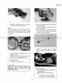
4. Throttle
To keep the throttle cable end, which is
held by the throttle lever, from contact-
ing the throttle grip, a collar is mounted
and the lever is properly curved.
Collar (90387 ·22726)
Lever (8G8-421:38-00
Lever (8J5-42138-00) and collar (9038,7-
Lever (8G8-42138-00) can not be used
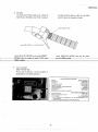
5. Tune-up label
(8K3-77743-00)
As an aid to service, a tune-up label is
attached to the intake silencer.
EI250 (BKal SPECIFIKATIONER
BENSIN
2. MOTOROLJA
3. TANDSTIFT
4. ELEKTRODEAVSTAND
5. TANDINSTALLNING
6. LAoFART (BRANSLEl JUSTERINGSSKRUV
7. TOMGANGSVARVTAL
8. BRANSLENIVA
9. KEDJEHUS OWEVOLYM OCH VISKOSITET
450 cc, GEAR OLJA
10. VARITORAVSTAND
11 VARIATOR SIDOFORSKJUTNING
1.
12.
-5
IS;RlJd~~~~~
MATTSPANNING
• FOR YTTERLIGARE INFORMATION SE l~
DENNA MODELL.
• SPECIFIKATIONER!<AN ANDRAS UTAN MEODELANOE.
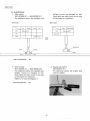
1980 ET250
D. ELECTRICAL
1. Main switch
(8F3-82508-20 ----j. 8J5-82508-21)
For additional safety, the headlight and
tailliqht circuits are changed so that
these lights are kept turned on as long
as the engine is in operation.
'79 model
'80 model
Yellow
Bille
ON
ON/LIGHT
LIGHT
Black/White
Black
Gray
Interchangeability:
No
3. Engine stop switch
(8E3-83976-01 )
For additional safety, the engine stop
switch is added.
2. Wire harness
(8H7-82590-20 -- 8K3-82590-20)
For additional safety, the headlight and
taillight circuits are changed so that
these lights are kept turned on as long
as the engine is in operation.
(Refer to "2-E Circuit Diagram.")
Interchangeability:
No
-6-
1980 ET250
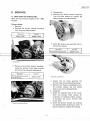
2. SERVICE
2. Disassembly
a. Separate the sliding sheave assembly
from the fixed sheave by rotating the
sliding sheave counterclockwise. .
A. NEW SERVICE PROCEDURE
(New service procedure applied to the 1980
ET250)
Primary shave
1. Removal
a. Remove the primary sheave mounting
bolt, using the sheave holder.
Tool name
Tool No.
Sheave holder
90890-01880
b. Install the sheave sub-assembly tool to
the primary sheave.
Tool name
Tool No.
Sheave sub-assembly tool
90890-01879
b. Remove the primary sheave assembly,
using the primary fixed sheave puller
bolt and primary sheave holding tool.
Tool name
Tool No.
Primary fixed sheave puller
bolt 1M18 P1.5)
90890-01881
1. Sheave sub-assembly tool
c. Loosen the six bolts securing the
primary sheave cap and sliding sheave.
d. Remove the sheave subassembly tool.
The primary sheave cap and sliding
sheave cap now be disassembled.
3. Inspection
a. Check the tapered ends of the crankshaft and primary fixed sheave for
scratches. If scratched unduly, replace.
If scratches are minor, burnish with
emery cloth.
b. Check the primary sheave cap bushing
and sliding sheave bushing for wear. If
beyond tolerance, replace the bushing.
1 Primary fixed sheave puller bolt
7
1980 ET250
.~
NOTE: - - - - - - - - - - - If bushing is installed tightly, remove the bushing using the bushing tool.
Bushing clearance, limit
Small bushing
Large bushing
Inside
0.25 mm (0.01 in)
0.25 mm (0.01 in)
Outside
0.25 mm (O.Ol in)
0.25 mm (0.01 in)
.'
Tool name
Bushing tool
Tool No.
90890-01877
1 Bushing tool
for free
Checkthtrspider and rollerfof'slllooth
movement and wear.
e. Check both sheaves for warping. If
warped, replace.
4. Reassembly
. a. Oil the points shown in the illustration.
Do not apply the grease on the portion
of X mark. For other parts. greasing is
unnecessary.
CAUTION: - - - - - ' - - - - - - . . ,
If the U -nut or cotter pin is removed for.
the greasing, replace it with ne\iV one.
... X Free from grease
... Greasing point
-8
1980 ET250
b. Install the component parts to the sliding sheave and the sheave cap.
e. Clean the tapered portions of crankshaft
and fixed sheave.
f. Fit the fixed sheave to.the tapered portion of crankshaft.
"
g. Apply engine oil to the threaded portion
of primary sheave bolt and its contact
surface with spring washer.
~._"
NOTE: - - - - - - - - - - - When installing the primary sheave cap to
the primary sliding sheave, be sure to align
the X mark on the sheave cap with that on
the spider.
h. Tighten the primary sheave mounting
bolt using primary sheave cap holding
tool.
c. Install the sheave subassembly tool and
tighten the cap.
d. Tighten the six primary sheave cap bolts
and remove the subassembly tool.
Tightening torque:
11 Nm (1.1 rn-kq. 8 ft-lb]
CAUTION: - - - - - - - - - . . ,
Make sure that the primary sheave cap
assembly slides in contact with the
fixed sheave boss.
Tightening torque:
First tightening the bolt to a torque of
A. then loosen it.
Retighten bolt to a final torque of
B.
A: 100 Nm (10 rn-ks. 72.5ft-lb)
B:60 Nm ( 6 rn-kq. 43.5 ft-lb)
-9..,..
1980 ET250
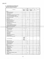
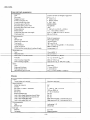
B. MAINTENANCE INTERVALS
[PERIODIC MAINTENANCE]
Every
20 hrs. or
400km
(250mi)
Check point
40 hrs. or
800 km
(500mi)
When
necessary
80 hrs or
1600km
(1000mi)
Seasonally
ENGINE:
a
a
a
a
a
a
Tightness of bolts and nuts
Bends. cracks and wear
Abnormal noise
Loose connection and breaks of fuel and pulse pipes
Loose connection and breaks of oil pipes
Loose connection and breaks of oil delivery pipe
a
a
a
a
a
a
a
.
a
Manual rope starter system
Carburetor
•
•
•
•
a
a
a
a
a
a
a
a
a
a
a
a
Fuel level
Operation of starter jet
a
a
Mixing adjuster (pilot screw)
Idling speed adjustment
a
Operation and adjustment of oil pump
Ignition timing
a
Cylinder compressions
Cylinder head/exhaust pipe decarbonize
a
Spark plug condition, gap and cleaning
Tightening of the cylinder head·.
a
a
Tightness of bolts and nuts
Wear on slide runners
a
a
a
a
a
a
a
a
a
a
a
a
a
Primary drive system
a
V-belt
Secondary drive system
Sheave distance
Sheave offset
Brake pad wear
Brake operation and adjustment
Guide wheel rubber
Wear of drive track wheel sprocket
Initial
100km
(60mi)
and
300 km
(200mi)
Drive track adjustment
Breaks in drive track
Bends in front and rear axles
Checking of lock washers
a
a
a
a
a
a
a
a
a
a
a
a
a
a
a
a
a
a
.
Drive chain adjustment
Drive chain oil level
I
BODY:
a
a
a
Tightness of bolts and nuts
Bends and cracks
Welded riveted. joints
a
Ski adjustment
a
Ski runner wear
.
a
Breaks in fuel tank
Cleaning of fuel tank
Fuel filter
a
a
Loose connection and breaks in fuel pipe
Breaks in oil tank
Oil filter
-10-
.
a
a
a
a
a
a
a
a
a
a
a
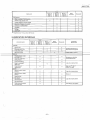
1980 ET250
Every
20 hrs. or
400km
(250 mil
Check point
40 hrs. or
800 km
(500mi)
80 hrs or
1600 km
(1DOOmi)
When
necessary
Seasonally
ELECTRICAL'
0
Wear. breakage of wire covering
0
0
Breaks in high-tension cord
0
0
Voltage regulator working voltage
Operation of engine stop switch
0
0
Operation of tether switch
0
0
Headlight
0
0
Taillight
0
0
Brake light
0
0
•• Retighten every 10 hours from the first use.
[LUBRICATION INTERVALS]
Every
lubrication point
20 hrs. or
400 km
(250mi)
40 hrs. or
BOOkm
(500 mil
80 hrs. or
1,600 km
(1.000mi)
When
necessary
Oil/Grease
Brand name
Seasonally
ENGINE:
Starter case
0
Oil pump control box
0
Pump drive cover
0
Oil.in.the.oiltank
0
Aercsheil grease #7 A or
Esso Beacon 325 grease
0,
< \YAMAL BF ? .cvcle oi
0
DRIVE:
Primary sheave weight
and roller pins
0
0
Secondary shaft and
sliding sheave
0
0
Front axle housing
0
0
Shaft 1 and shaft 2
(Slide rail)
0
Molybdenum disulfide
snowmobile grease
Light all-purpose grease
0
0
0
Gear oil API "GL-3"
SAE #75 or #80
Steering column lower
bearing
0
0
Light all-purpose grease
Steering column upper
bearing
0
0
Motor oil
Steering links
0
0
Ski column
0
0
Ski wear plate
0
0
Ski retaining pin
0
0
Brake wire end stopper
and brake lever
0
0
Drive chain oil
replacement
BODY:
-11-
Light all-purpose grease
Esso Beacon 325 grease
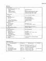
1980 ET250
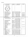
C. SPECIFICATIONS
NOTE:
General
(Compared with 1979 ET250)
Model:
Model (I.B.M. No.)
•
Frame 1.0. and starting number
I
* ... New specification
EngineLD. and starting number
ET250('80) (8K3)
• 8H7-054001
• 5246-054001
Dimension:
Overall length
Overall width {std]
Overall height (w/windshield)
• 2.435 mm
905 mm
1,040 mm
Engine
Description:
Engine type
Fan cooled, two stroke fi-port. single cylinder
Engine model
5246
246 crrr'
Displacement
Bore X stroke
Effective compression ratio
73 X 59mm
6.3: 1
Starting system
Recoil hand starter
Ignition system
C.O.I.
fWt=e oilinjection
LlfIfricaflon system
.
Cylinder head:
Combustion chamber volume (with spark plug)
32.1 crrr'
Compression chamber type
Dome
Head gasket thickness
0.5mm
+
squish
Cylinder:
Material
Bore size
Taper limit
Out of round limit
Cast iron sleeves aluminum cylinder
73 mm
0.05 mm (0.0020 in)
0.01 mm (0.0004 in)
Piston:
Piston skirt clearance
0.045
(Measuring point)
(10 mm from piston skirt end)
Piston over size
1st 73.25 mm
2nd 73.50 mm
3rd 73.75 mm
4th 74.00 mm
18 X 55 mm
Piston pin outside diameter X length
~
0.050 mm
Piston ring:
Piston ring design (Top)
Keystone
Piston ring design [Znd]
Keystone
Ring end gap (Installed) (Top)
Ring end gap (Installed) (Znd)
0.3~
0.3~
0.5 mm
0.5 mm
Small end bearing:
Type
Needle bearing
Big end bearing:
Type
Needle bearing
Crankshaft:
Crankshaft assembly width (A)
+0
56 -0.05 mm
Crankshaft deflection (0)
0,02 mm
-12-
1980 ET250
Connecting rod large end side clearance (e)
Connecting rod small end deflection (5)
O.5mm
2 mm
A
$<'~
40 mm
f--- -
,
-
40mm
S
Crank pin outside diameter X length
Crank pin type
Crank bearinq type (Left) X qtv
Crank bearing type (Right) X q'tv
Crank oil seal type (Left) X q'tv
Crank oil seal type (Ri9ht) X q'tv
24 X 55 mm
Solid shaft
#6306 C3 specta I treatment x 1 pc.
#6206 C3 X 1 pc.
FPJ30-72-8 x 1 pc.
FPJ30-48-8 X 1 pc.
*
*
Carburetor:
Type and manufacture/quantity
I.D. mark
Main jet (M.J.)
Slow adjusting screw (Air screw) (S.A.)
Slow jet (S,J)
Intermediate jet (I.J.l
Starter jet (St.J.)
Fuel level (F.L.)
Idling engine speed
CDX38-32 KEIHIN SEIKI X 1
8H700
#138
2.0 turns out
#50
#40
0.96 mm
+
1.5 ± 3.5 mm
1,300 r/min
Main jet setting chart:
~re
Altitude
Sea level
e
- 20
(-22°F)
(- 4
-30
D
•
~
Lubrication:
Autolube pump Autolube pump Autolube pump Autolube pump Autolube pump Autolubepump Oil tank capacity
Oil grade
<io-c
0"C
to-e
(14°F)
(32 OF)
(50 DFI
20 D e
(68°Fl
#130
#138
#130
#138
14QOm
20GOm or more
e
#138
mo-
'" 700m
~
0
QF)
#130
-#138_
--#125
-'-
#130
Color code
Minimum stroke
Maximum stroke
Reduction ratio
Output Min.
Output Max.
Green
0.20 ~ 0.26 mm (0.008 ~ 0.01 in)
1.85 ~ 2.05 mm (0.073 ~ 0.081 in)
1/40
13.5 cm 3/h/l ,300 r/min (0.46 oz/h/l ,300 r/min)
440 cm 3/h/6,500 r/min 114.9 oz/h/6,500 r/min)
2.2 liter
YAMALU 8E 2-cycle oil
-13-
1980 ET250
Drive and track suspension
Transmission:
Type
Drive ratio
v-bett
automatic centrifugal engagement
Secondary spring Part No.
3.5; 1 ~ 1 ; 1
3200 r(min
90501-55345
Red-Red
90508-40080
Secondary spring Color code
Not painted
Secondary spring pre-load (Twist)
160"
266 ± 2 mm (10.47 ± 0.08 in)
11 ± 1 mm 10.43 ± 0.04 in)
31.6 X 1.099 mm (1.24 X 43.3 in)
26 mm 11.02 in)
Engagement rpm
Primary spring Part No.
Primary spring Color code
Sheave distance
Sheave off-set
v-belt width and outer line length
V-bert wear limit
•
•
•
•
Track suspension:
Type
Slide rail suspension
Damper type
Oil and gas damper
Slide runner wear limit
Length on ground
10 mm 10.4 in)
381 mm(15in)
25 ~ 30 rnm/j 0 kg (0.98
650 mm 125.6 in)
Wheel sprocket material and number of teeth
Polyethylene l1T
Track width
Track deflection
~
1.18 in(22 lb]
Secondary drive:
Type
--rretrOCfI6 rirati 6
Chain (#40K-l)
~
",/'-
,"
Chain housing oil quantity
-2 mm 10.4 ~ ~08 in)
450 em' (15.21 oz]
Chain housing oil grade
Gear oil API "GL-3" SAE #75 or #80
Free play
10
+5
Brake:
Type
Disc brake
Brake pad thickness
7.3 mm 10.29 in)
1 mm 10.04 in)
0.2 ~ 1.0 mm (0.008
Brake pad wear limit
Gap between pad and disc
~
0.039 in)
Chassis
Frame:
Frame design and material
Aluminum and steel
Steering system:
Caster (ski column)
Camber
Ski length X width X thickness
Ski stance
Ski toe-out
Steering linkage type
Lock to lock angle (Steering column) Right
Lock to lock angle (Steering column) Left
Lock to lock angle (Ski) Right
Lock to lock angle (Ski) Left
25°
0"
1000 X 136 X 2.6 mm
750 mm 138.6 in)
~ 6 mm 10.24 in)
Tie-rod
•
o
55" 15'
55"15'
Right hand ski 24.9". Left hand ski 27.6°
Right hand ski 27.6", Left hand ski 24.9'
Front suspension:
Type
Leaf spring
Damper type
Oil damper
X 3
Fuel tank:
Capacity
22.7 liter
Fuel grade
Regular gasoline
-14-
1980 ET250
Electrical
Ignition system:
Type-flywheel magneto IC.D.1. Type)
Model/manufacturer
Voltage
F3T355/MITSUBISHI
12V
9.0n at 20°C (68°F) (White/Red~Black)
350f! at 20°C 168°F) (Brown-Black)
15.0n at 20°C (68°F) (Blue-Black)
Pulser coil resistance
Charging coil resistance
Ignition timing:
B.T.D.C.
1.2
± 0.1
mm 10.05
± 0.004 in)
Ignition coil:
Model: Manufacturer
Spark 9ap
.
Primary winding resistance
Secondary winding resistance
Diode (Yes or No)
F6T411/MITSUBISHI
9 mm (0.35 in)/300 r/min
11 mm 10.43 in)/3,000 r/min
LOn at 20°C (68° F)
5.9kn at 20°C (68°F)
No
Spark plug:
NGK B-8HS X 1 pc.
0.5 ~ 0.6 mm (0.020 ~ 0.024 in)
Type and quantity
Spark pluq gap
Spark plug cap:
Type
worse suppressor resistance
Rubber type with noise suppressor
5 kn at 20°C (68°F)
C.D.I. unit:
Model/manufacturer
8H4-20/MITSUBISHI
Lighting system:
Lighting output
12V-l00W
0.19f! at 20°C (68°F) (Yellow-Black)
Lighting coil resistance
Head light type
Bulb wattape/q'tv
Tail/brake light wattage
Semi shield
12V-45/40W X 1 pc.
12V-8W/23W
AC. regulator:
Model/manufacturer
TRIZ-24B HITACHI or S8516B TOSHIBA
13.8 ± 0.5V
Voltage
Tightening torque
Part to be tightened'
[Engine]
Spark plug
Cylinder head
Flywheel- magneto
Fand and flywheel magneto
Pully and flywheel magneto
Flywheel base
Thread size
M14P1.25
MB P1.25
M16
M6
M8
M6
P1.0
P1.0
Pl.25
Pl.0
-15-
Tightening torque
28 Nm (2.8 m-kg, 20 ft-Ib)
First: 20 Nm (2.0 m-kg, 14.5 ft-Ib)
Final: 25 Nm (2.5 m-kg, 18 ft-lb)
73 Nm (7.3 m-kg, 53 tt-lb)
10 Nm (1.0 m-kg, 7 ft-lb)
16 Nm (1.6 m-kg, 7.5 ft-lb)
7 Nm (0.7 m-kg, 5 ft-lbl
Remarks
Use LOCK- TITE
1980 ET250
Part to be tightened
Crankcase left and right
Tightening torque
Thread size
M6
Pl.0
Remarks
7 Nm 10.7 m-kg. 5 ft-Ib)
Tightening sequence
~-l
~<P~
®5
-
rd
1@
--
-
@2
~71 ~
T
Crankcase and engine bracket
Cylinder and ring nut
Pump drive cover and crankcase
Pump drive cover and crankcase
Starter case and crankcase
Cylinder head and air shroud
Crankcase and air shroud
Air shroud 1 and 2
Pump drive cover 1 and 2
1 ono ?
Startercase and duct
[Drive and track suspension]
* Primary sliding sheave and cap
*
Installation of primary sheave
Ml0Pl.25
M8 Pl.25
M8 Pl.25
M6 Pl.0
M6 Pl.0
M6 Pl.0
M6 P1.0
M6 P1.0
M6 Pl.0
" . pn.R
M5 PO.8
30
23
23
10
10
7
7
7
7
5
5
Nm
Nm
Nm
Nm
Nm
Nm
Nm
Nm
Nm
Nm
Nm
13.0 m-kg.
12.3 rn-kq.
12.3 m-kg.
11.0 m-kq.
11.0 m-kg.
10.7 rn-kq.
10.7 m-kg.
10.7 m-kg.
10.7 m-kg.
10.5 m-ko
10.5 rn-ko.
22 ft-lb)
16.5 ft-Ib)
16.5 ft-Ib)
7 ft-lbl
7 tt-lbl
5 ft-Ibl
5 tt-lb)
5 tt-tb)
5 tt-lb)
3.5 tt-lb!
3.5 ft-lb)
M6 Pl.0
UNF 1/2"
11 Nm 11.1 m-kg. 8 ft-lb]
Initial:l00 Nmll0m-kg. 72.5 ft-lb) Use motoroil
Use LOCK- TITE
Use LOCK-TlTE
Use
Use
Use
Use
LOCK-TITE
LOCK-TITE
LOCK-TITE
LOCK-TITE
Use LOCK-TITE
Loosen once and retighten:
Chaincase housing and frame
Front axle housing and frame
Front axle IR.H.)
Chain drive sprocket
Chain driven sprocket
Housing cap
Chain tensioner adjusting lock nut
P1.25
P1.25
P1.25
Pl.25
Pl.25
Pl.25
Pl.0
P1.0
P1.0
60 Nm 16.0 m-kg. 43.5 ft-lb)
25 Nm 12.5 m-kg. 18 tt-lb)
25 Nm 12.5 m-kq. 18 ft-lb)
80 Nm 18.0 m-kg. 58 ft-Ibl
40 Nm 14.0 m-kg. 29 ft-lb)
25 Nm 12.5 m-kg. 18 ft-Ibl
15 Nm 11.5 m-kq. 11 ft-tb)
33 Nm 13.3 m-kq. 24 ft-lb)
5 Nm 10.5 m-kg. 3.5 ft-Ibl
55 Nm 15.5 m-kg. 40 ft-Ibl
40 Nm 14.0 m-kg. 29 tt-lb)
80 Nm 18.0m-kg. 58 ft-lb)
25 Nm 12.5 m-kg. 18 tt-Ibl
25 Nm 12.5 m-kq. 18 ft-lb)
25 Nm 12.5 rn-kq. 18 ft-lb)
2.5 Nm 10.25 m-kg. 2 ft-tb]
6 Nm 10.6 m-kq. 4.5 ft-Ibl
4 Nm 10.4 m-kg. 3 ft-Ibl
Ml0 P1.25
M8 Pl.25
M8 Pl.25
Ml0 Pl.25
Ml0 Pl.25
Ml0Pl.25
Ml0Pl.25
M8 Pl.25
M8 Pl.25
M8 Pl.25
30 Nm 13.0 m-kg. 22 ft-Ib)
14 Nm 11.4 rn-kq, 10 ft-Ib)
20 Nm 12.0 m-kg. 14.5 tt-lb)
30 Nm 13.0 m-kg. 22 ft-Ibl
30 Nm 13.0 rn-kq. 22 tt-lb)
30 Nm 13.0 m-kq. 22 ft-lb]
30 Nm 13.0 m-kq. 22 tt-lb)
20 Nm 12.0 m-kg. 14.5 tt-lb)
14Nmll.4m-kg.l0ft-lbl.
14 Nm 11.4 m-kg. 10 tt-lb)
M8 Pl.25
M8 Pl.25
M20 Pl.0
M12Pl.25
M8 Pl.25
M8 Pl.25
Ml0 P1.25
-
Sprocket wheel and front axle
Shaft 1 and frame
Pivot arm 1 and sliding frame 1
Suspension wheel
Spring hook
Sliding frame 1
Rear guide wheel
Sliding runner 1
Sliding runner 2
Stopper
Ml0
Ml0
M12
M8
M8
M8
M6
M6
M6
[Chassisl
Engine mounting bolt (nut)
Ski runner
Steering column and gate
Steering. relay rod adjusting nut
Universal joint
Outside arm and ski column
Steering relay ass'v
Steering lower bracket
Steering column 1 and 2
Steering gate
-16-
Use cotter pin
Use LOCK-TITE
Use LOCK-TITE
1980 ET250
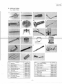
D. SPECIAL TOOLS
(For 1980 ET250)
No.
Description
.
Tool No.
Dial gauge
90890-03097
1-b
Dial gauge stand NO.2
90890-01195
1-c
Needle (56 mml
90890-03098
z-a
2-b
2-c
Flywheel puller bolt
Flywheel puller attachment
Flywheel puller screw
90890-011106
Drive handle
90890-01817
Flywheel puller body
90890.01848
4
5-a
5-b
Crankcase separation tool
90890-01135
Spacer (.p80 X 55 mm)
90B90-OJ 818
Crank installer bolt
90890-01275
Crank installer bolt adaptor
(M16! {for Rightl
90890-01280
-17-
Tool No.
Crank installer bolt adaptor
(M 121 (for Left!
90B90-01279
5-d
Crank installer pot
90890-01274
6
Rotor holding tool
90890-01235
7
Sheave holder
90890-01880
8
Primary fixed sheave puller (M 181
90890-01881
9
Sheave sub-assembly tool
90890-01879
10
Bushing tool
90890-01877
11
Sheave gauge
90890-01875
12
Pocket tester
90890-03104
5-c
90890-01804
2-e
Description
NO.
90890-01803
2-d
3
.
I
l-a
13
Electro tester
90890-03021
14
AC. Regulator checker
90890-03090
1980 ET250
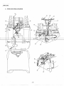
E. WIRE ROUTING DIAGRAM
@-
-18-
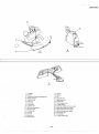
1980 ET250
160mm
o
B
c
1.
2.
3.
4.
5.
6.
7.
8.
9.
10.
1L
12.
13.
14.
15.
16.
To taillight
Fuel pipe
Through pipe inside the steering gate
Voltage regulator
Ground to body
To oil tank
To oil purnp
To carburetor
To ignition coil
Wire harness assembly
Ground to body
Fuel level pipe
Fuel cock
Grommet
Starter wire
Fuel cock wire
17. Oil pipe
1a. Oil filter
19. Clip
20. Left brake wire
21 Right brake wire
22. Throttle wire
23. Decompression wire
24. To brake caliper
25. Brake light switch lead wire coupler
26. Beam switch lead wire coupler
27. Tether switch lead wire coupler
28. Main switch lead wire coupler
29. Ground lead wire
30. To head light
31. Oil tank breather pipe
-19-
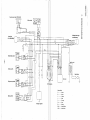
(0
OJ
a
m
-i
:n
~
:rl
2
G)
C
~L
»
G)
:rl
»
s:
y
L
y Gy ~
L
B/W
o
Brake light switch
,(,
y
a
P
I
i
y~~
Tether switch
B
(0
Y Gy 0
L
B
M-H
/1"
I
( p~
Spark plug
.AV)~
, -_ _
L
ceDI
I
aneta
Color Code
G
Beam switch
Voltage regulator
Green
B
Black
Y
Yeliow
L
o
Blue
Orange
Gy
Gray
Br
Brown
B/W
WjR
Black/White
White!Red
'"
ot
a