1
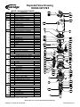
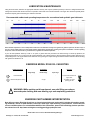
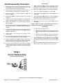
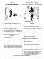
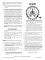
Service Manual
1000 Series Digger models
Example Part Number
1000
96
5
4
f
97
E
5
Model
Ratio
Shaft
Bail Boss
Motor
Supplier
Motor
Number
Cover
Input
This service manual is effective:
S/N: 89000 to current
date: 1-2010 to CURRENT
version:Smd100096-54f97e5_ab
NOTE: Individual customer specifications (spindle
mounting, sprocket pilot, brake assembly, etc.) may
vary from exploded drawing and standard part numbers shown. If applicable, refer to customer drawing
for details.
Exploded View Drawing
100096-54F97E5
Eskridge
ITEM
1
2
3
4
5
5A
5B
5C
5D
5E
5F
6
7
7A
7B
7C
7D
7E
7F
7G
7H
7J
7K
7L
8
8A
8B
8C
10
10A
10B
10C
11
11A
11B
11C
12
12A
12B
12C
12D
13
13A
13B
13C
13D
13E
13F
13G
14
15
15A
15B
15C
15D
15E
15F
16
MODEL 100096-54F97E5 DIGGER
QTY
1
1
1
1
(1)
1
3
3
6
6
3
1
(1)
1
3
3
6
6
3
6
6
6
3
1
1
1
1
2
1
1
1
3
1
1
1
1
1
6
12
3
20
20
4
4
6
1
1
*
1
1
1
1
DESCRIPTION
BASE-"F" FLANGLESS
OUTPUT SHAFT: 5-1/4" SQUARE
COVER (4 BOLT "E")
INPUT GEAR
CARRIER ASSEMBLY- PRIMARY
CARRIER
CLUSTER GEAR
PLANET SHAFT
BEARING (CAGE & ROLLER)
THRUST WASHER
ROLL PIN
SUN GEAR
CARRIER ASSEMBLY- SECONDARY
CARRIER
PLANET GEAR
PLANET SHAFT
BEARING CONE
BEARING CUP
RETAINING RING
RETAINING RING
WASHER
SHIM
ROLL PIN
PLATE - SEC CARRIER RETAINER
RING GEARS & SPACER
RING GEAR - PRIMARY
RING GEAR - SECONDARY
RING SPACER
THRUST WASHERS & BEARINGS
BEARING THRUST RACE - PRIMARY
BEARING - PRIMARY THRUST
BEARING THRUST RACE - INPUT
SEALS & O-RINGS
O-RING
O-RING
OUTPUT SHAFT SEAL
OUTPUT SHAFT BEARINGS
OUTER CONE
OUTER CUP
INNER CONE
INNER CUP
HARDWARE
SHCS (3/8-16 X 1) GR8
SHCS (1/2-13 X 1-1/2) GR8
FHS C.S. (3/8-24 X 1)GR8
HHCS (3/4-10 X 11.5) GR8
HARDWASHER (3/4 X 1.25 OD)
HHCS (3/4-10 X 1.75) GR8
LOCKWASHER (3/4 MED)
PIPE PLUG (3/4 NPT MAGNETIC)
MISCELLANEOUS
SEAL CARRIER
BAIL ASSEMBLY
SHIM
LOCK RING
SPLIT RING (L-SEGMENT)
RETAINING RING
MOTOR
PART NO.
60-004-3014
60-004-4222L
60-004-1564
60-004-1462
60-005-2043
60-004-1024
60-004-1182
60-004-1272
01-105-0510
60-004-1881
01-153-0150
60-004-1222
60-005-2083
60-004-1044
60-004-1232
60-004-1262
01-102-0210
01-103-0210
01-160-0490
01-160-0500
60-004-1291
60-004-1321
01-153-0150
60-004-1352
60-004-1213
60-004-1243
60-004-1253
01-112-0350
01-112-0340
01-112-0060
01-402-0670
01-402-0660
01-405-0810
01-102-0190
01-103-0190
01-102-0220
01-103-0220
01-150-1110
01-150-0570
01-150-1590
01-150-1720
01-166-0350
01-150-1890
01-166-0360
01-207-0100
60-004-1922
60-005-1622
60-004-1311
60-004-1472
60-004-1482
01-160-0510
01-304-0970
13F
13G
16
13D
13E
15B
14
14
3
15F
11B
10C
4
10A
5A
8A
7C
7D
7E
7G
7K
7B
7E
7D
7H
7J
7H
7F
6
10B
5C
5E
5D
5B
5F
5E
13B
8C
11B
13C
7L
7A
8B
15D
15E
15C
12C
12D
11B
14
1
14
11C
12B
12A
11A
15A
13A
2
X100096-54F97E5aa 05-12-10 ECN- HWP
Model D1000 service manual, SM 100096-54F97E5_AB Page Eskridge, Inc. Olathe, KS. 913-782-1238
www.eskridgeinc.com
Lubrication & Maintenance
Using the chart below, determine an appropriate lubricant viscosity. Use only EP (extreme pressure) or API GL-5 designated lubricants.
Change the lubricant after the first 50 hours of operation and at 500 hour intervals thereafter. The auger drive should be partially disassembled to inspect gears and bearings at 1000 hour intervals.
Recommended ambient and operating temperatures for conventional and synthetic gear lubricants
-50
-25
0
25
50
75
100
125
150
175
200
225
250 F
107
121 C
80W90 conventional
75W90 conventional
85W140 conventional
Min Ambient/operating temp
Max Operating temp
Max Ambient temp
75W90 synthetic
80W140 synthetic
-45
-32
-18
-4
10
24
38
52
66
79
93
Note: Ambient temperature is the air temperature measured in the immediate vicinity of the gearbox. A gearbox exposed to the direct rays of
the sun or other radiant heat sources will operate at higher temperatures and therefore must be given special consideration. The max operating
temp must not be exceeded under any circumstances, regardless of ambient temperature.
If your unit was specified “shaft up” or with a “-Z” option, a grease zerk was provided in the base housing. For shaft-up operation, the
output bearing will not run in oil and must be grease lubricated. Use a lithium based or general purpose bearing grease sparingly every
50 operating hours or at regular maintenance intervals. Over-greasing the output bearing should be avoided as it tends to fill the housing
with grease and thicken the oil
ESKRIDGE MODEL D1000 OIL CAPACITIES
Operating Position
Oil Capacity
Single stage
Horizontal Shaft
-
Vertical Shaft (Pinion Down)
!
Double stage
Oil Level
Triple stage
-
9.5 gal
To horizontal centerline of
auger drive
To midway on upper/
primary gear set
WARNING: While working on this equipment, use safe lifting procedures,
wear adequate clothing and wear hearing, eye and respiratory protection.
ESKRIDGE PART NUMBER INTERPRETATION
Note: All non custom Eskridge Geardrives are issued a descriptive part number which includes information regarding the Model, means of shaft retention, base style, shaft style, input mounting, input shaft size, overall ratio and
various available options. For a detailed breakdown of this information, please refer to Eskridge product specification sheets found at: http://www.eskridgeinc.com/diggers/diggerprodspecs.html
Model D1000 service manual, SM 100096-54F97E5_AB Page Eskridge, Inc. Olathe, KS. 913-782-1238
www.eskridgeinc.com
Unit Disassembly Procedure
Disassembly
1)
Rotate planet gears (5B) to check for abnormal noise or
roughness in bearings (5D) or planet shafts (5C). If further
inspection or replacement is required, proceed as follows.
2)
Drive roll pins (5F) completely into the planet shafts (5C).
3)
Press or drive planet shafts (5C) out of carrier (5A).
Remove the twenty hex-head capscrews (13D) and
flat washers (13E).
4)
Remove planet gears (5B) and thrust washers (5E) from the
carrier (5A).
4)
Separate bail (15B) from gearbox and remove from digger
assembly.
5)
Inspect the planet gear (5B) bearing bore, planet shaft (5C) and
rollers (5D). Check for spalling, bruising or other damage.
5)
Install two hex-head capscrews (13D) into cover (3) to retain
gearbox assembly together while removing motor fasteners.
6)
Replace any parts where abnormal wear is found.
6)
Remove motor (16) from cover (3) and remove temporary
fasteners (13D).
7)
Use 3/16 inch pin punch to remove roll pins (5F) from planet
shafts (5C).
7)
Remove cover (3), thrust bearings (10A, 10B & 10C), remove
input gear (4). Inspect o-ring (11B); discard if damaged or
deformed.
1)
Scribe a diagonal line across the outside of the unit from the
bail (15B) to the base (1) before disassembly to aid in the
proper positioning of pieces during reassembly.
2)
Remove magnetic drain plugs (14) and drain oil from unit.
The oil will drain out faster and more completely if warm.
3)
8)
9)
Lift Stage I planet carrier assembly (5) out of the unit. Remove
ring gear spacer (8C) and inspect o-ring (11B); discard if
damaged or deformed.
NOTE: If either the rollers or the planet shafts (pins) are
damaged, both components should be replaced.
Reassembly
1)
Remove Stage II sun gear (6) from secondary carrier
assembly (7).
10) Remove the three 3/8-24 flat head capscrews (13C) securing
the carrier retaining plate (7L) to the output shaft (2).
a)
Set planet washer (5E) on work table, place planet gear
(5B) onto washer and insert bearings (5D) into planet
bore.
b)
Place planet washer (5E) onto top of planet gear then
slide the gear into carrier (5A). (Oriented as shown.)
2)
Planet shafts (5C) should be installed with chamfered end of
3/16 inch hole toward outside diameter of the carrier (5A).
This will aid in alignment of holes while inserting roll pins
(5F).
3)
Drive a roll pin (5F) through the carrier hole and into the planet
shaft to retain the parts. Repeat for other planet gears.
11) Remove remaining ring gear (8B) and Stage II carrier assembly (7). Inspect gear to gear and gear to base o-ring(s) (11B),
discard and replace any damaged or deformed o-rings.
12) The unit is now separated into subassemblies. The area(s)
requiring repair should be identified by thorough inspection
of the individual components after they have been cleaned
and dried.
To install rollers in planet gear bore:
Stage I
Carrier Subassembly
(Items 5A, 5B, 5C, 5D, 5E, & 5F)
5C
5E
5D
5B
5F
5E
5A
Model D1000 service manual, SM100096-54F97E5_AB Page Eskridge, Inc. Olathe, KS. 913-782-1238
www.eskridgeinc.com
Base Subassembly
Stage II
Carrier Subassembly
(Items 1, 2, 11C, 12A, 12B, 12C, 12D, 14, 15A, 15C, 15D, & 15E)
(Items 7A, 7B, 7C, 7D, 7E, 7F, 7G, 7H, 7J & 7K)
7C
7D
7E
7G
7K
7B
7E
7D
7H
7J
7H
7F
15D
15E
15C
11B
14
1
12B
12A
11A
15A
14
7A
11C
Rotate planet gears (7B) to check for abnormal noise or
roughness in bearings (7D, 7E). If further inspection or
replacement is required, proceed as follows.
13A
2
Disassembly
1)
12C
12D
Disassembly
1) Remove the seal carrier retaining screws (13A) and seal carrier (15A) from unit. Inspect seal (11C) and o-ring (11A) for
signs of wear or damage and replace as necessary.
2)
Remove the lock ring (15D) using a heel bar or puller; if using
a heel bar, be sure not to pry against the cage of the inner
output shaft bearing (12C). Remove the split ring segments
(15E) and shims (15C).
2)
Removing retaining ring (7F), washer (7H) and shims (7J)
from planet shaft (7D).
3)
Press planet shafts (7C) out of carrier (7A).
4)
Remove planet gears (7B) and washer (7H) from carrier.
5)
Inspect the planet gear (7B), bearing cone (7D), bearing cup
(7E) and planet shaft (7C). Check for spalling, bruising or
other damage. Replace components as necessary; bearing
need to be replaced as a cup and cone set.
Caution: Since the output shaft is no longer retained, care
should be taken to avoid personal injury. Care should also be
taken not to damage it when it is pressed through base.
6)
Replace any parts where abnormal wear is found.
3)
Reassembly
1)
Rebuild Stage II planet carrier assembly in reverse order
using any needed new parts.
2)
Install bearing cones (7D) into planet gear bearing cups (7E).
Place washer (7H) onto interior carrier spot faced surface.
3)
Insert planet gear assembly into carrier (7A).
Slide planet shaft (7C) Into carrier planet assembly and align planet pin notch with roll pin in carrier.
4)
Place shims (7J) and washer (7H) onto planet shaft. Install
retaining ring (7F). Rotate plant gears by hand to test bearing
preload. Correct bearing preload on the planet gears requires
50-75 in-lbs rotating torque. If gear doesn’t rotate remove a
shim and test again until a smooth loaded rotation is developed. Repeat for remaining planet gears.
Base (1) should be set pinion side down, as shown, on a plate
or table. Press output shaft through the bottom of base by applying a load to top end (internal end) of shaft until it passes
through inner shaft bearing cone (12C).
Note: Removing the shaft from the base assembly damages
the shaft seal and the seal will need to be replaced.
4)
A gear puller may be used to remove the outer bearing cone
(12A) from the shaft (2). If reusing old bearing cone, do not
pull on or damage roller cage.
5)
Inspect inner and outer bearing cups (12A, 12B, 12C & 12D).
If cups are damaged, drive them out using a brass drift and
utilizing the bearing knock-out notches in the base (1)
Reassembly
1)
Clean all foreign material from magnetic oil plug (14) located
on the side of the base (1).
2)
Place base (1) (output side up, opposite shown) on the table.
3)
Apply a layer of lithium or general purpose bearing grease to
the roller contact surface of outer bearing cup (12A).
4)
Press outer bearing cone (12B) (large end down as shown)
onto the shaft until it seats against the shoulder.
Model D1000 service manual, SM100096-54F97E5_AB Page Eskridge, Inc. Olathe, KS. 913-782-1238
www.eskridgeinc.com
Note: Press bearing cone onto output shaft by pressing on inner race only. DO NOT press on roller cage, as it may damage
bearing.
5)
Place the shaft (2) with the bearing (12A) into the base (1).
6)
Flip this assembly, resting the base (1) on the end of the output shaft (2).
7)
Apply a layer of lithium or general purpose bearing grease
to the roller contact surface of the inner cup (12D). Press the
inner bearing cone (12C) (large end up as shown) onto the
shaft (2) until it is seated against inner bearing cup (12D).
8)
Without the shaft seal (11C) installed, the preload may result
in a rolling torque that varies between 50 to 300 in-lb. The
bearing preload should be tailored to your application; a lowspeed application may require a high pre-load, high-speed
applications usually benefit from low pre-load. Adding shims
(15C) will increase the pre-load on the bearing set. Determine your pre-load requirement and install shims to obtain
this pre-load. Install the Load-N-Lock™ segments (15E) over
the shims (15C) and into the groove in the shaft (2). Finally,
install the lock ring (15D) over the segments (15E).
9)
b) As seen from above, start with the top planet gear and
position it’s timing mark pointing straight down. Next, rotate the lower left planet gear counterclockwise as indicated in the timing diagram. Then rotate the lower right
planet gear clockwise as indicated.
Install o-ring (11A) onto seal carrier (15A). Lubricate inner lip
of new shaft seal (11B) and slide seal carrier assembly onto
the shaft (2). Install seal carrier fasteners (13A) and torque
to 30 ft-lbs.
c) Set the input gear (4) and the input thrust race (10C) into
the center of the primary planet carrier assembly.
All subassembly service or repairs should be complete
at this time. Continue to Unit Assembly to complete unit
buildup.
d) If compound primary ring gear (8A) was not removed
during disassembly, then skip to step 9. Otherwise, bolt
to the inside of the cover (3) with twelve bolts (13B). Use
a removable thread locking compound on the threads
of the bolts. Tighten to 110 ft.-lbs. dry or 80 ft.-lbs. lubricated.
Unit Assembly
1)
When all subassemblies are complete, the unit is ready to be
assembled.
2)
Install the Stage II carrier assembly onto the output shaft;
align the splines of the carrier (7A) with the splines of the
shaft (2) and slide the carrier onto the shaft.
3)
Install carrier retaining plate (7L) & secure using 3/8-24 Flathead capscrews (13C).
4)
Lubricate o-ring (11B) and install on the pilot of the
Stage II ring gear (8B).
Caution: Hold ring gear by outside or use lifting device to prevent injury.
5)
Install Stage II sun gear (6) into Stage II carrier assembly.
6)
Align gear teeth of ring gear (8B) with the gear teeth of the
planet gears (7B) and place on base. Align mounting holes
of ring gear with holes in base. Using the scribed line made
during disassembly for reference.
7)
Place Stage I carrier (5A) onto Stage II sun gear (6).
8)
Lubricate o-ring (11B) and install on the pilot of the
Stage I ring gear spacer (8B). Install spacer.
9)
Compound primary timing instructions:
a) The planet gears will now need to be timed. Refer to
the diagram. The planet gears each have a timing mark,
usually a round punch locate timing marks on planet
gear (5B).
9)
Install thrust washer (10A) onto primary carrier then install
thrust bearing (10B) and thrust washer (10A).
10) Lubricate o-ring (11B) and install on the pilot of the cover
(3).
11) Noting the scribed line made during disassembly, install the
cover (3). Install 2 fasteners (13D) to retain unit together.
12) Ensure the unit spins freely by using a splined shaft to drive
the input gear (4). If unit does not rotate freely for one revolution remove cover and verify primary planet gearing is timed
correctly.
13) Install motor (16) onto cover (3) and align motor shifting
mechanism with bail relief hole. Install motor fasteners.
14) Remove two temporally fasteners installed in step 11. Place
bail (15B) onto assembly and aligning holes in bail and cover
using scribed line made during disassembly as a reference.
Install and torque the 20 3/4-10 hex head capscrews (13D)
with flat washers (13E). The torque for the capscrews is
380 ft-lbs dry, 280 ft-lbs if fasteners are lubricated.
15) Fill the unit to the proper level, as specified, with GL5 EP
80/90 gear oil after it is sealed with the motor.
The digger is now ready to use.
Model D1000 service manual, SM100096-54F97E5_AB Page Eskridge, Inc. Olathe, KS. 913-782-1238
www.eskridgeinc.com
![E-CORE[イー・コア]直管形LEDベースライト モデルチェンジのお知らせ](http://vs1.manualzilla.com/store/data/006543989_3-984d60b7a35b5c906359937cb576f3e5-150x150.png)