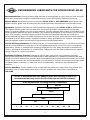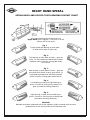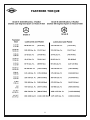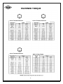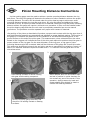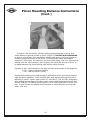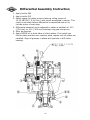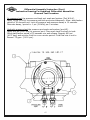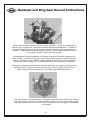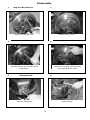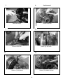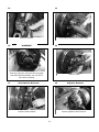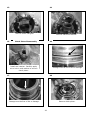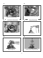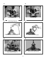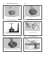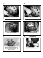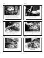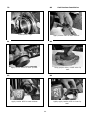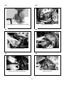
1
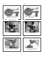
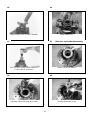
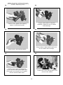
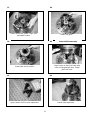
Service Manual
Axle
42R
Hydralock Differential
ASM-0182
February 2003
FOREWORD
This manual has been prepared to provide the customer and the maintenance personnel with
information and instructions on the maintenance and repair of the Spicer Off Highway Products.
Extreme care has been exercised in the design and selection of materials and manufacturing of these
units. The slight outlay in personal attention and cost required to provide regular and proper
lubrication and inspection at stated intervals, and such adjustments as may be indicated will be
reimbursed many times in low cost operation and trouble free service.
In order to become familiar with the various parts of the product, it’s principle of operation,
troubleshooting, and adjustments. It is urged that the mechanics study the instructions in this
manual carefully and use it as a reference when performing maintenance and repair operations.
Whenever repair or replacement of component parts is required, only Spicer Off Highway Products
approved parts as listed in the applicable parts manual should be used. Use of “will fit” or nonapproved parts may endanger proper operation and performance of the equipment. Spicer Off
Highway products does not warrant repair or replacement parts, nor failures resulting from the use
of parts which are not supplied or approved by Spicer Off Highway Products. Important: Always
furnish the distributor with the serial and model number when ordering parts.
CAUTION
To reduce the chance of personal injury and/or property damage, the following
instructions must be observed.
Proper service and repair are important to the safety of the service technician and the safe, reliable
operation of the machine. If replacement parts are required the part must be replaced with one of
the same part number or with an equivalent part. Do not use a replacement part of lesser quality.
The service procedures recommended in this manual are effective methods of performing service and
repair. Some of these procedures require the use of tools specifically designed for the purpose.
Accordingly, anyone who intends to use a replacement parts service procedure or tool, which is not
recommended by SOHPD, must first determine that neither his safety nor the safe operation of the
machine will be jeopardized by the replacement part, service procedure or tool selected.
It is important to note that this manual contains various ‘Cautions’ and ‘Notices’ that must be
carefully observed in order to reduce the risk of personal injury during service or repair, or the
possibility that improper service or repair may damage the unit or render it unsafe. It is also
important that these ‘Cautions’ and ‘Notices’ are not exhaustive, because it is impossible to warn of
all the possible hazardous consequences that might result from failure to following these instructions.
1
Table of Contents
2
CLEANING and INSPECTION
Cleaning
Inspection
Caution
Bearings
Clean all parts thoroughly using solvent
type cleaning fluid. It is recommended
that parts be immersed in cleaning fluid
and agitated slowly until parts are
thoroughly cleaned of all old lubricants
and foreign materials.
The importance of careful and thorough
inspection of all parts cannot be
overstressed. Replacement of all parts
showing indication of wear or stress will
eliminate costly and avoidable failures at
a later date.
Care should be exercised to avoid skin
rashes, fire hazards and inhalation of
vapors when using solvent type cleaners.
Carefully inspect all rollers, cages, and
cups for wear, chipping or nicks to
determine fitness of bearings for further
use. Do not replace a bearing without
replacing the mating cup or cone at the
same time. After inspection, dip bearings
in clean light oil and wrap in clean lintless
cloth or paper to protect them until
installed.
Bearings
Remove bearings from cleaning fluid and
strike larger side of cone flat against a
block of wood to dislodge solidified
particles of lubricant. Immerse again in
cleaning fluid to flush out particles.
Repeat above operation until bearings
are thoroughly clean. When drying
bearings, use moisture-free compressed
air, being careful to direct air stream
across bearings as to avoid spinning.
Bearings may be rotated slowly by hand
to facilitate the drying process.
Oil Seals, Gaskets and
Retaining Rings
Replacement of spring loaded oil seals,
gaskets, and snap rings is more
economical when unit is disassembled
than to risk premature overhaul to
replace these parts at a future time. Loss
of lubricant through a worn seal may
result in failure of other more expensive
parts of the assembly. Sealing member
should be handled carefully, particularly
when being installed. Cutting, scratching,
or curling under lip of seal seriously
impairs its efficiency. At reassembly,
lubricate lips of oil seals with
Multipurpose Lithium grease. “Grade 2”
(MS107C).
Housing
Clean interior and exterior of housings,
bearing caps, etc., thoroughly. Cast parts
may be cleaned in hot solution tanks with
mild alkali solutions, providing these
parts do not have ground or polished
surfaces. Parts should remain in solution
long enough to be thoroughly cleaned
and heated. This will aid the evaporation
of the cleaning solution and rinse water.
Parts cleaned in solution tanks must be
thoroughly rinsed with clean water to
remove all traces of alkali. Cast parts
may also be cleaned with steam cleaner.
Gears and Shafts
Caution
Care should be exercised to avoid skin
rashes and inhalation of vapors when
using alkali cleaners. Thoroughly dry all
parts cleaned immediately by using
moisture-free compressed air or soft
lintless absorbent wiping rags free of
abrasive materials such as metal filings,
contaminated oil or laping compound.
3
If magna-flux process is available, use
process to check parts. Examine teeth
and ground and polished surfaces of all
gears and shafts carefully for wear,
pitting, chipping, nicks, cracks, or
scoring. If gear teeth are cracked or
show spots where case hardening is worn
through, replace with new gear. Small
nicks may be removed with suitable
hone. Inspect shafts to make certain they
are not sprung, bent, or splines twisted,
and that shafts are true. Differential
pinions and side gears must be replaced
as sets. Differential ring gear and spiral
pinion must also be replaced as a set if
either is damaged.
CLEANING and INSPECTION (Cont.)
Housing and Covers
At Reassembly Apply Thread
Locking Compound Where Noted
Inspect housing, covers, planet spider,
and differential case to be certain they
are thoroughly cleaned and that mating
surfaces, bearing bores, etc., are free
from nicks or burrs. Check all parts
carefully for evidence of cracks or
condition which cause subsequent oil
leaks or failures.
Guidelines for application where to apply:
A. On bolts, capscrews, and studs
(anchor end).
B. On nuts, apply compound to the male
thread of the mating fastener.
C. Apply compound to coat the full length
and circumference of thread
engagement.
D. Remove excess compound from mating
parts after fastener installation.
Reassembly of Axle
The reassembly instructions describe the
procedure to be followed when
reassembling and installing components
of axle. Instructions covering reassembly
of opposite side is identical unless
otherwise noted.
Important: Class 8.8 and 10.9 and
12.9 fastening hardware has been used
in the production of he axle assemblies
covered in the manual. A table of proper
torque values for the fastener classes
above are provided within this manual.
The class of hardware may be
determined by the markings contained of
the head of each capscrew. Class 12.9
torque values needs to be used on all
sockethead capscrew used with this
assembly. Torque values specified in text
of this manual are for class 8.8, 10.9
hardware where presently used in
production. On all axles being
overhauled, bolts should be identified as
described above and torque value chart
consulted for correct torque.
4
RECOMMENDED LUBRICANTS FOR SPICER DRIVE AXLES
Recommendations: Extreme pressure gear lubricant is recommended for use in all drive-steer and rigid
drive axles except where explicitly stated differently by Spicer Off-Highway Products Engineering.
Mineral Based: Acceptable lubricants must meet API GL-5/MT or MIL-PRF2105E qualifications. The
highest viscosity grade must be used given the prevailing ambient temperatures from the chart below.
Synthetics: Synthetic lubricants are recommended providing they meet API GL-5/MT-1 qualifications.
The highest viscosity grade must be used given the prevailing ambient temperatures from the chart
below. In general synthetic oils have a lower pressure viscosity response than mineral oil lubricants as the
contact pressure between the gears increases. This produces a thickening of the mineral oil at the contact
point. This increase in viscosity helps to maintain lubricant film thickness reducing the possibility of
surface and spalling fatigue. Synthetic lubricants do not thicken as much under pressure unless specifically
formulated to do so. Before using a synthetic lubricant in heavy applications, the customer must check
with the lubricant supplier on the issue of high-pressure lubricant applications.
Normal Oil Change Intervals: Oil change intervals for mineral based lubricants in normal environmental
and duty cycle conditions is 1000 hours in all off-highway applications and 10,000 miles in on-highway
applications. Severe or sustained high operating temperature or very dusty atmospheric conditions will
result in accelerated deterioration or contamination. Judgement must be used to determine the required
change intervals for extreme conditions.
Extended Oil Change Interval: Extended oil service may result when using synthetic lubricants.
Appropriate change intervals must be determined for each application by measuring oxidation and wear
metals over time to determine a baseline. Wear metal analysis can provide useful information, but an axle
should not be removed from service based solely on this analysis. Vehicles, which are prone to high levels
of ingested water in the axle, or water as a result of condensation, should not use extended drain
intervals.
Friction Modifiers: Friction modifiers may be used with the lubricant to reduce Posi-Torq (limited slip)
differential noise or liquid cooled brake noise. If friction modifiers are used, follow instructions on
TSB 278E.
The use of aftermarket lubricant additives other than those specified is not
recommended and may reduce the life of the axle and void the warranty!
Viscosity Based on Prevailing Ambient Temperature
SAE 140
80W140 / 85W140
SAE90
80W90
75W90
75W
DEG.C.
F.
-40
-40
-30
-22
-20
-4
-10
14
0
32
10
50
5
20
68
30
86
40
104
50
122
LEFT HAND SPIRAL
SPIRAL BEVEL AND HYPOID TOOTH BEARING CONTACT CHART
CONVEX
SIDE – USE
THIS PAGE
All contact bearings shown below are on
Left Hand spiral ring gear – the drive is on the
convex side of the tooth.
Fig. 1
Typical preferred bearing on both sides
of tooth while under a light load.
Fig. 2
Toe bearing on both sides of tooth – gear set
noisy. To move bearing toward heel increase
backlash within limits by moving gear away
from pinion.
Fig. 3
Heel bearing on both sides of tooth – gear set
noisy and could result in early gear failure. To
move bearing toward toe decrease backlash
within limits by moving gear toward pinion.
Fig. 4
Low bearing on gear and high bearing on
pinion. Correct by pulling pinion away from
gear (increase mounting distance).
Fig. 5
High bearing on gear and low bearing on
pinion. Correct by moving pinion toward gear
(decrease mounting distance).
Backlash
Backlash should be measured with a dial indicator rigidly mounted with the stem
perpendicular to the tooth surface at the extreme heel.
6
RIGHT HAND SPIRAL
SPIRAL BEVEL AND HYPOID TOOTH BEARING CONTACT CHART
CONVEX
SIDE – USE
THIS PAGE
All contact bearings shown below are on
Right Hand spiral ring gear – the drive is on the
convex side of the tooth.
Fig. 1
Typical preferred bearing on both sides
of tooth while under a light load.
Fig. 2
Toe bearing on both sides of tooth – gear set
noisy. To move bearing toward heel increase
backlash within limits by moving gear away
from pinion.
Fig. 3
Heel bearing on both sides of tooth – gear set
noisy and could result in early gear failure. To
move bearing toward toe decrease backlash
within limits by moving gear toward pinion.
Fig. 4
Low bearing on gear and high bearing on
pinion. Correct by pulling pinion away from
gear (increase mounting distance).
Fig. 5
High bearing on gear and low bearing on
pinion. Correct by moving pinion toward gear
(decrease mounting distance).
Backlash
Backlash should be measured with a dial indicator rigidly mounted with the stem
perpendicular to the tooth surface at the extreme heel.
7
FASTENER TORQUE
8
FASTENER TORQUE
Coarse Threaded Fasteners
Coarse Threaded Fasteners
Coarse Threaded Fasteners
9
PINION STAKING
Staking of the pinion end to the inner pinion is required when the inner pinion bearing or the pinion
shaft and ring gear are being replaced.
If a staking groove is in the pinion shaft, use procedure shown in Figure “A” and a square end
staking tool.
If pinion has no staking groove use procedure in Figure “B” and a standard prick punch to up-set the
metal over the bearing inner race.
1/8”
FIGURE A
OPTIONAL CONSTRUCTION
(NO STAKING GROOVE)
FIGURE B
10
STAKE IN 6 PLACES
EXPLODED VIEW
11
DIFFERENTIAL ASSEMBLY DESCRIPTION
ITEM
No.
1
2
3
4
5
6
7
8
9
10
11
12
13
14
15
16
17
18
19
20
21
22
23
24
25
26
27
28
29
30
31
32
33
34
35
36
37
38
39
40
41
42
43
44
45
DESCRIPTION
Not Used In This Model
Adjusting Nut Lockwasher
Adjusting Nut Capscrew
Differential Adjusting Nut
Differential Bearing Cup
Differential Bearing Cone
Differential Case Seal
Carrier Cap Washer
Carrier Cap Capscrew
Case Capscrew
Case Washer
Plain Half Case
Side Thrust Washer
Side Gear
Pinion Gear Thrust Washer
Pinion Gear
Needle Roller Thrust Washer
Pinion Needle Rollers
Needle Roller Thrust Washer
Differential Cross
Clutch Side Gear
Side Thrust Washer
Ring Gear Capscrew
Ring Gear
Clutch Housing
Clutch Driver
Snap Ring Driver
Friction Plate
Reaction Plate
Clutch Plate
Piston Outer Seal
Piston Inner Seal
Piston Wave Seal
Flange Half Case
Case Washer
Case Capscrew
Case Plug
Piston Rings Rotary Seal
Gear Nut
Inner Pinion Bearing
Pinion Gear
Differential Carrier and Cap Assy
Differential Adjusting Nut
Not Used In This Model
Adjusting Nut Washer
ITEM
No.
46
47
48
49
50
51
52
53
54
55
56
57
57A
58
58A
59
60
61
62
63
64
64A
65
66
67
68
69
70
71
72
73
74
75
76
77
78
79
80
81
81A
81B
82
83
84
85
QTY
1
1
1
2
2
1
4
4
12
12
1
1
1
4
4
8
328
4
1
1
1
12
1
1
1
1
6
7
1
1
1
1
1
3
3
1
2
12
1
1
1
2
1
12
DESCRIPTION
Adjusting Nut Capscrew
Lip Seal Inner
Seal Retainer
Plug
Cap Screws - Seal Retainer
Lip Seal Outer
Nipple
O Ring Nipple
Back Up Ring Tank Port
Square Cut Seal Tank Port
Back Up Ring Pressure Port
Cap
Cap
Pressure Nipple
Nipple O-Ring
Seal Square Cut Pressure Port
Plug
Inner Pinion Bearing Cone
Inner Pinion Bearing Cup
Pinion Bearing Spacer Kit
Bearing Cage Shim - .007
Bearing Cage Shim - .010
Pinion Bearing Cage Assy
Outer Pinion Bearing Cup
Outer Pinion Bearing Cone
Pinion Seal
Not Used In This Model
Pinion Seal Retainer
Grease Fitting
Seal Retainer Lockwasher
Seal Retainer Capscrew
Seal Retainer Lockwasher
Seal Retainer Capscrew
Grease Seal
Thrust Washer
Not Used In This Model
V-Ring Seal
Not Used In This Model
Flange
O Ring
Spacer O Ring
Flange Nut
Differential Case Assy
Differential Body Assy
Drive Gear and Pinion Set
QTY
1
1
1
2
3
1
1
1
1
1
1
1
1
1
1
1
2
1
1
1
AR
AR
1
1
1
1
1
2
7
7
1
1
1
1
1
1
1
1
1
1
1
1
Pinion Bearing Rolling Torque Instructions
Install bearing cage and pinion shaft assembly in differential carrier
without bearing cage shims. Use (4) oil pinion seal retainer bolts with
flat washers to pull pinion shaft assembly fully into carrier assembly.
Make sure oil passages are aligned. Install (3) flat washers on each
bolt to prevent them from bottoming.
Temporarily install companion flange on end of pinion shaft without
installing pinion oil seal retainer. Install companion flange retaining tool on
companion flange and torque flange nut to 600 LBF-LB (850 Nm).
Remove companion flange retaining tool and use “inch-pound” torque
wrench to check bearing preload. If bearing preload is not between 13
and 23 LBF-IN (1-3 Nm) the flange will have to be removed and the
cage disassembled. Shims can then be added or removed as needed
to obtain proper reading. Add shims to increase preload, remove shims
to reduce preload. Reassemble unit and check again.
13
Pinion Mounting Distance Instructions
A pinion setting gauge must be used to achieve a precise mounting distance between the ring
and pinion. The use of the gauge will determine the amount of shims needed to achieve the proper
mounting distance. The shims will be placed under the pinion bearing cage to achieve an exact
mounting distance between the ring gear and pinion. By using the gauge and adding the proper
thickness of shims, an optimum tooth contact will be obtained. Setting the ring and pinion mounting
distance without the gauge will require a trial and error procedure. A shim must be installed under
the pinion bearing cage and then the unit must be completely assembled per service manual
instructions. The procedure must be repeated until proper tooth contact is obtained.
T
The position of the pinion as described will produce a proper tooth contact with the ring gear when it
and the differential assembly are assembled and adjusted to proper backlash setting. The function of
the gauge is to measure the distance from the centerline of the differential bearing bores to the
ground surface on the end of the pinion gear. This measurement, when subtracted from the value
etched on the ring gear will indicate the size of the shim pack required to position the pinion gear in
proper relation to the ring gear. On the outer diameter of the ring gear, a ring gear to pinion
mounting distance value will be etched. Add half the thickness of the gauge bar. Record this value.
This value may be different on each ring and pinion set due to manufacturing variations. Insert a 4”
base 5/32” diameter extension depth micrometer and 5”- 6” extension into the guide bore of the
micrometer arbor.
1
2
Paint bearing surfaces of carrier housing
with gear tooth marking compound.
Mount adapter discs on micrometer arbor
and set in position in carrier housing. Do
not contact any part of the carrier in this
operation. Apply pressure by hand and
rotate adapter discs slightly to obtain a
contact with bearing surfaces.
3
Remove checking gauge assembly and
check for full bearing contact on bearing
surfaces.
14
Pinion Mounting Distance Instructions
(Cont.)
4
If contact is full and proper, position checking gauge assembly in carrier and
check distance to ground surface on pinion (Figure 4). DO NOT APPLY PRESSURE
to arbor or micrometer. Turn micrometer carefully and evenly until tip of extension
contacts the ground surface of the pinion. In the assembly shown the distance
measures 5.159 inches, the reading on the micrometer being .159 inch. Subtract this
reading from the value etched on the ring gear, this equals the amount of shims to
be added between the pinion bearing cage and the carrier housing.
Example: 5.159 - Value etched on ring gear and half the thickness of the gauge bar.
5.129 – Initial micrometer reading.
.030 – Add this value in shims.
Remove bolts holding pinion bearing cage in differential carrier and remove bearing
cage and pinion assembly. Install required shim pack and reinstall cage and pinion
assembly in carrier. Tighten cage screws 177-199 LBF-FT (240-270 Nm) temporarily.
After adding required amount of shims, again mount checking gauge assembly and
recheck reading. The reading should now be .159 (5.159 inches) plus or minus .002
inch. In other words, the reading should be equal to value etched on the ring gear
within .004 inch.
15
Differential Assembly Instruction
1. Apply Loctite 262
2. Apply Loctite 515
3. Select spacer to obtain a pinion bearing rolling torque of
13-23 LBF/IN (1.5-2.6 Nm ) with pinion assembled in carrier. This
check to be made before differential is assembled and not to
include pinion oil seal drag.
4. Differential assembly to be adjusted to obtain a backlash of .010
(.254 mm) to .014 (.355 mm) between ring gear and pinion.
5. Shim as required
6. Apply MS266 oil to both sides of clutch plates. First install one
friction plate and then one reaction plate, repeat until all plates are
installed. Align all grooves in plates with grooves in diff clutch
housing.
16
Differential Assembly Instruction (Cont.)
Instruction Drawing For Hydralock Differential Assemblies.
Pressure Test Procedure.
Air pressure test the pressure and tank port seals and system (Port W & V).
Apply 12 psi (83 kPa) to pressure and tank ports simultaneously. Allow stabilization
period of 20 seconds min. Lock off pressure and measure decay in 10 seconds.
Alternate decay / period is .1 psi (.69 kPa) per 5 minutes.
Hydraulic pressure test the pressure port seals and system (port W).
Apply 600 psi (4137 kPa) to pressure port. Place open tank line back to tank.
Allow stabilization period of 20 seconds min and release. Reapply 600 psi
(4137 kpa) and monitor fluid for a one minute period. Fluid flow rate is not to
Exceed .75 gpm (2.83 l pm).
17
Backlash and Ring Gear Runout Instructions
Tighten bearing adjusting nuts to achieve “Zero Backlash”. Loosen the adjusting nut
opposite the ring gear until it no longer contacts the differential assembly. Tighten the
nut on the ring gear side until the ring gear contacts the pinion and zero backlash is
obtained. Tighten the other adjusting nut until snug. Mount a dial indicator as shown
in the photo, plunger contacting the gear tooth.
Set backlash by loosening adjuster on ring gear side then alternately tightening the
other adjuster. Gently rock ring gear back and forth while observing the dial indicator
reading. Compare the dial indicator reading against the specs found in the Assembly
Instructions section, page (16). Continue procedure until proper spec is obtained.
Once proper backlash has been obtained tighten adjusting nut opposite ring gear to set
bearing preload. Using only thumb and forefinger, move ring gear back and forth.
When ring gear becomes difficult to move bearing preload has been set.
Use dial indicator to check back face of ring gear. Rotate at least one full turn. Runout
must not exceed .005 [0,12mm] total indicator reading. If runout is excessive remove
assembly and check for burrs or dirt under mounting surface of ring gear. Reassemble
and recheck.
18
Disassembly
1
Ring Gear Bolt Removal
2
Loosen (4) ring gear nuts.
Remove the (4) nuts.
3
4
Carefully remove the (4) bolts with a
brass driver.
5
Rotate the ring gear until the empty
holes align with the pinion.
Fitting Removal
6
Remove fitting caps.
Loosen fittings.
19
7
8
Remove fittings.
Cap Removal
Loosen lock bolt.
9
10
Remove lock bolt.
Loosen (4) cap bolts.
11
12
Remove (4) cap bolts.
Loosen (3) retainer screws.
20
13
14
Remove screws.
15
Use rubber hammer to loosen caps.
“WARNING”
16
Once the caps are removed the ring gear
and differential assembly can roll out of
the carrier housing.
17
Remove caps.
Seal Retainer Removal
18
Remove seal retainer.
Adjuster Removal
Loosen adjusters and remove.
21
19
Differential Assembly Removal
20
Remove differential assembly from
housing.
21
Note: Empty holes must be aligned
with pinion centerline before removal.
Case Half Disassembly
22
Carefully remove piston rings. Note:
Edges of rings can cut fingers.
Remove bearing cup.
23
24
Remove bearing cup opposite side.
Remove differential case seal.
22
25
Ring Gear Removal
26
Remove all ring gear bolts with brass
driver.
Loosen and remove all ring gear nuts.
27
28
Use rubber hammer to remove ring gear.
Place wooden blocks under ring gear.
29
Flanged Case Half Removal
30
Remove flanged case half bolts.
Use rubber hammer to remove flanged
case half.
23
31
Friction and Reaction Plate
Removal
32
Remove reaction plates.
Note: Friction and reaction plates may fall
out when flanged case half is removed.
33
34
Remove friction discs.
Clutch Driver Removal
Remove snap ring.
36
35
Remove clutch driver.
Case Half Removal
Remove bolts.
24
37
38
Side Gears and Spider
Disassembly
Remove side thrust washer.
Be sure to mark case halves before
separating case halves.
39
40
Inspect cross and gears for wear.
Replace as needed.
Remove the cross and pinion
assembly. Mark the cross and diff
body section for easy alignment
during reassemble.
Remove differential side gear.
41
42
Remove thrust washers. Number each
washer as removed.
Remove differential pinion gears one at
a time and place with proper thrust
washer.
25
43
44
Remove clutch side gear.
45
Remove side thrust washer.
Clutch Piston Disassembly
46
Install seal retainer. Carefully apply
air to hole in seal retainer to remove
clutch piston.
Passage must be free of dirt or damage.
47
48
Passage must be free of dirt or damage.
Remove clutch piston.
26
49
50
Remove inner and outer piston seals.
Remove piston wave spring.
51
Seal Retainer Disassembly
52
Remove inner and outer lip seals.
Flange Disassembly
Loosen flange nut.
53
54
Remove flange nut.
Carefully remove flange with puller.
27
55
56
Remove spacer O ring.
57
Remove O ring.
Pinion Cage Removal
58
Remove bolts from seal retainer.
Remove pinion seal retainer.
59
60
Remove pinion cage assembly.
Install flange and flange nut.
28
61
Seal Retainer Disassembly
62
Remove thrust washer.
63
Remove grease seal.
Pinion Cage Disassembly
64
Remove pinion seal.
Place pinion inside of press. Press pinion,
inner and outer cones out of cage.
65
66
Remove inner and outer bearing cups.
Pinion Disassembly
Remove pinion bearing spacer.
29
67
68
Press inner bearing off of pinion.
Check for wear on pinion and bearing.
Replace as required.
30
Reassembly
1
Pinion Reassembly
2
Note: All parts must be lubricated prior to
reassembly, do not assemble dry.
Stake pinion and inner race four places
equally around diameter.
Press inner pinion bearing on pinion.
3
4
Pinion Cage Reassembly
Install pinion bearing spacer and .010
(.0254mm) shim (reuse old shim if
reusing gear set).
Press inner pinion bearing cone onto
pinion.
5
6
Press inner and outer bearing cups in
cage.
Place bearing cage on pinion, install
outer pinion bearing cone.
31
7
8
Check/adjust pinion bearing
rolling torque following the
procedure listed in the
Assembly Instructions section
pages ( 3 and 13).
Pinion mounting distance must
be set following the procedure
on pages (14 and 15).
Press bearing into cage assembly.
9
Seal Retainer Installation
10
Use correct driver to install the grease
seal and pinion seal (2) in the seal
retainer.
11
Install thrust washer into pinion seal
retainer.
Pinion Cage Installation
12
Apply Loctite #515 to bearing cage
shims and joining surfaces in a
continuous bead. Cover entire surface.
Install bearing cage shim.
32
13
14
Position pinion cage assembly in carrier
housing.
Remove flange nut and flange.
15
16
Apply Loctite #515 to pinion bearing
cage in a continuous bead across
entire surface.
Install pinion seal retainer.
17
18
Install seal retainer capscrews.
Apply Loctite #262 to seal retainer
capscrews.
33
19
20
Torque (7) capscrews to
177-199 LBF-FT (240-270 Nm).
21
Torque (1) capscrew to 74-81 LBF-FT
(100-110 Nm).
Flange Reassembly
22
Install “O” ring.
Install spacer “O” ring.
23
24
Grease seal seat journal of drive
flange with MS-107C.
Install V-Ring seal onto flange.
34
25
26
Apply Loctite #515 to pinion threads.
Install flange nut.
27
28
Side Gear and Spider Reassembly
Install side thrust washer.
Run nut down, then torque flange nut
to 600 LBF-LB (815 Nm).
29
30
Lubricate clutch side gear and install.
Grease differential cross.
35
31
Note: If new parts are not being used the cross
must be assembled using the numbering system as
directed in disassembly process.
32
Using a rubber band to facilitate
assembly, install one row of needle
roller bearings.
Position inner needle roller bearing
spacer on differential spider.
33
34
Using another rubber band install outer
row of needle roller bearings.
Install center roller bearing spacer.
36
35
Position pinion gear on needles as
shown. Remove first rubber band. Slide
pinion gear over second row of needles,
remove second rubber band.
Install outer roller bearing spacer and
pinion thrust washer.
36
37
38
Install differential spider. Align case
and spider marks.
Install side gear.
39
40
Case Half Reassembly
Align marks on plain half case with
mark on flanged half case. Install
plain half case.
Install side thrust washer.
41
42
Apply Loctite #262 to case capscrews.
Install case capscrews.
37
43
44
Torque to 74-81 LBF-FT (100-110 Nm).
Clutch Driver Reassembly
Install clutch driver. Note: The five
holes in the clutch housing.
45
46 Friction and Reaction Plate Reassembly
Install first friction plate.
Note: Align plate holes with holes in
clutch housing.
Install snap ring.
47
48
Install first reaction plate.
Note: Align reaction plate holes with holes
in friction plate.
Install all plates in order.
Note: See assembly instructions
page (16).
38
49
Clutch Piston Reassembly
50
Lubricate flange half case.
Install piston wave spring.
51
52
Install inner piston seal.
Install piston outer seal.
53
54
Use rubber hammer to install clutch
piston.
Lubricate seals.
39
55
Flanged Half Case Reassembly
56
Install bearing using press.
Align marks and install flange half
case onto clutch housing.
57
58
Apply Loctite #262 to capscrews.
Install capscrews.
59
60
Install bearing and seal.
Torque capscrews to 44-48 LBF-FT
(60-65 Nm)
40
61
Ring Gear Reassembly
62
Use rubber hammer to seat ring gear
flush. Align holes in ring gear and case.
Install ring gear.
63
64
“Note: Leave four bolts out for pinion clearance.”
Apply Loctite #262 to cap screws and
install. Leave (4) capscrews out.
Install nuts
65
66
Torque nuts 150-168 LBF-FT
(203-228 Nm).
Differential Assembly
Install diff body assembly into carrier.
“Note: Four holes rotated to the bottom.”
41
67
68
Install differential bearing cup.
Install differential adjusting nut.
69
70
Install cap and capscrews.
Tighten lightly do not torque.
71
72
Note: See Assembly Instructions for
backlash setting procedure and ring
gear runout checking procedure. See
pages (16 and 18).
Cap Installation
Apply Loctite #262 to capscrews.
42
73
74
Install caps and capscrews. Torque to
300-360 LBF-FT (407-488 Nm).
Recheck backlash, correct as needed.
Apply Loctite #262 to adjusting lock
capscrew and install.
75
76
Torque capscrew to 25-28 LBF-FT
(34-38 Nm).
Rotate empty ring gear holes to the
top.
77
78
Install capscrews and nuts.
Torque nuts 150-168 LBF-FT
(203-228 Nm).
43
79
80
Install piston rings.
Seal Retainer Installation
Apply Loctite #262 to seal retainer.
81
82
Apply Loctite #620 to outer lip seal.
Using proper driver, install outer lip
seal.
83
84
Apply Loctite #620 to seal retainer.
Lightly apply Loctite #620 to inner lip
seal.
44
85
86
Use proper driver to install inner lip seal.
Lubricate piston rings.
87
88
Install seal retainer guide.
Install seal retainer.
89
90
Apply Loctite #262 to capscrews.
Install capscrews.
45
91
92
Torque screws 10-20 LBF-IN
(1-2 Nm).
Fitting Installation
Install O Ring on fitting.
93
94
Repeat procedure for other fitting.
Install back up ring and then the square
cut seal on fitting.
95
96
Tighten fittings to 15 LBF-FT (20 Nm)
and install caps.
Install fittings.
46
Copyright 2013 Dana Holding Corporation
All content is subject to copyright by Dana and may not
be reproduced in whole or in part by any means,
electronic or otherwise, without prior written approval.
THIS INFORMATION IS NOT INTENDED FOR SALE OR
RESALE, AND THIS NOTICE MUST REMAIN ON ALL
COPIES.
For product inquiries or support,
visit www.dana.com or call 419-887-6445
For other service publications,
visit www.SpicerParts.com/literature.asp
For online service parts ordering,
visit www.SpicerParts.com/order.asp