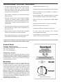
1
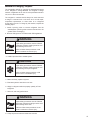
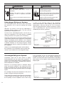
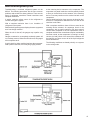
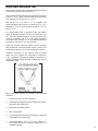
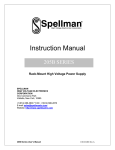
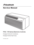
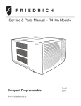
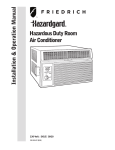
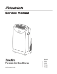
Service Manual
Model:
Room Air Conditioners
HG-ServMan (04-09)
SH15L30-C
SH15L30-D
SH20L30-C
SH20L30-D
TECHNICAL SUPPORT
CONTACT INFORMATION
FRIEDRICH AIR CONDITIONING CO.
Post Office Box 1540 · San Antonio, Texas 78295-1540
4200 N. Pan Am Expressway · San Antonio, Texas 78218-5212
(210) 357-4400 · FAX (210) 357-4490
www.friedrich.com
Printed in the U.S.A.
Table Of Contents
Important Safety Information ....................................................................................................................2-4
Introduction ..................................................................................................................................................4
Unit Identification .........................................................................................................................................5
Performance Specifications and Installation Data .......................................................................................6
Electrical Data ..............................................................................................................................................7
HazardGard Special Features ......................................................................................................................8
Control Panel ................................................................................................................................................8
Component Definitions .................................................................................................................................9
Component Testing ................................................................................................................................10-11
Sealed System Refrigeration Repairs .........................................................................................................12
Refrigerant Charging .............................................................................................................................12-15
Compressor Checks ..............................................................................................................................16-17
Compressor Replacement ..........................................................................................................................18
Routine Maintenance .............................................................................................................................19-20
Troubleshooting .....................................................................................................................................21-23
Wiring Diagram and Schematic ..................................................................................................................24
Warranty .....................................................................................................................................................25
1
IMPORTANT SAFETY INFORMATION
The information contained in this manual is intended for use by a qualified service technician who is familiar
with the safety procedures required for installation and repair, and who is equipped with the proper tools and
test instruments required to service this product.
Installation or repairs made by unqualified persons can result in subjecting the unqualified person making
such repairs as well as the persons being served by the equipment to hazards resulting in injury or electrical
shock which can be serious or even fatal.
Safety warnings have been placed throughout this manual to alert you to potential hazards that may be
encountered. If you install or perform service on equipment, it is your responsibility to read and obey these
warnings to guard against any bodily injury or property damage which may result to you or others.
Your safety and the safety of others are very important.
We have provided many important safety messages in this manual and on your appliance. Always read
and obey all safety messages.
This is a safety Alert symbol.
This symbol alerts you to potential hazards that can kill or hurt you and others.
All safety messages will follow the safety alert symbol with the word “WARNING”
or “CAUTION”. These words mean:
WARNING
You can be killed or seriously injured if you do not follow instructions.
CAUTION
You can receive minor or moderate injury if you do not follow instructions.
All safety messages will tell you what the potential hazard is, tell you how to reduce the chance of injury,
and tell you what will happen if the instructions are not followed.
NOTICE
A message to alert you of potential property damage will have the
word “NOTICE”. Potential property damage can occur if instructions
are not followed.
PERSONAL INJURY OR DEATH HAZARDS
ELECTRICAL HAZARDS:
2
•
Unplug and/or disconnect all electrical power to the unit before performing inspections,
maintenance, or service.
•
Make sure to follow proper lockout/tag out procedures.
•
Always work in the company of a qualified assistant if possible.
•
Capacitors, even when disconnected from the electrical power source, retain an electrical charge
potential capable of causing electric shock or electrocution.
•
Handle, discharge, and test capacitors according to safe, established, standards, and approved
procedures.
•
Extreme care, proper judgment, and safety procedures must be exercised if it becomes necessary
to test or troubleshoot equipment with the power on to the unit.
•
Do not spray or pour water on the return air grille, discharge air grille, evaporator coil, control panel,
and sleeve on the room side of the air conditioning unit while cleaning.
•
Electrical component malfunction caused by water could result in electric shock or other electrically
unsafe conditions when the power is restored and the unit is turned on, even after the exterior is dry.
•
Never operate the A/C unit with wet hands.
•
Use air conditioner on a single dedicated circuit within the specified amperage rating.
•
Use on a properly grounded outlet only.
•
Do not remove ground prong of plug.
•
Do not cut or modify the power supply cord.
•
Do not use extension cords with the unit.
•
Follow all safety precautions and use proper and adequate protective safety aids such as: gloves,
goggles, clothing, adequately insulated tools, and testing equipment etc.
•
Failure to follow proper safety procedures and/or these warnings can result in serious injury or death.
REFRIGERATION SYSTEM HAZARDS:
•
Use approved standard refrigerant recovering procedures and equipment to relieve pressure before
opening system for repair.
•
Do not allow liquid refrigerant to contact skin. Direct contact with liquid refrigerant can result in minor
to moderate injury.
•
Be extremely careful when using an oxy-acetylene torch. Direct contact with the torch’s flame or hot
surfaces can cause serious burns.
•
Make sure to protect personal and surrounding property with fire proof materials.
•
Have a fire extinguisher at hand while using a torch.
•
Provide adequate ventilation to vent off toxic fumes, and work with a qualified assistant whenever
possible.
•
Always use a pressure regulator when using dry nitrogen to test the sealed refrigeration system for
leaks, flushing etc.
•
Make sure to follow all safety precautions and to use proper protective safety aids such as: gloves,
safety glasses, clothing etc.
•
Failure to follow proper safety procedures and/or these warnings can result in serious injury or death.
MECHANICAL HAZARDS:
•
Extreme care, proper judgment and all safety procedures must be followed when testing,
troubleshooting, handling, or working around unit with moving and/or rotating parts.
•
Be careful when, handling and working around exposed edges and corners of sleeve, chassis, and
other unit components especially the sharp fins of the indoor and outdoor coils.
•
Use proper and adequate protective aids such as: gloves, clothing, safety glasses etc.
•
Failure to follow proper safety procedures and/or these warnings can result in serious injury or death.
3
PROPERTY DAMAGE HAZARDS
FIRE DAMAGE HAZARDS:
•
Read the Installation/Operation Manual for this air conditioning unit prior to operating.
•
Use air conditioner on a single dedicated circuit within the specified amperage rating.
•
Connect to a properly grounded outlet only.
•
Do not remove ground prong of plug.
•
Do not cut or modify the power supply cord.
•
Do not use extension cords with the unit.
•
Failure to follow these instructions can result in fire and minor to serious property damage.
WATER DAMAGE HAZARDS:
•
Improper installation maintenance, or servicing of the air conditioner unit, or not following the above
Safety Warnings can result in water damage to personal items or property.
•
Insure that the unit has a sufficient pitch to the outside to allow water to drain from the unit.
•
Do not drill holes in the bottom of the drain pan or the underside of the unit.
•
Failure to follow these instructions can result in result in damage to the unit and/or minor to serious
property damage.
INTRODUCTION
This service manual is designed to be used in conjunction with the installation manuals provided with each unit.
This service manual was written to assist the professional HVAC service technician to quickly and accurately
diagnose and repair any malfunctions of this product.
This manual, therefore, will deal with all subjects in a general nature. (i.e. All text will pertain to all models).
IMPORTANT: It will be necessary for you to accurately identify the unit you are
servicing, so you can be certain of a proper diagnosis and repair.
(See Unit Identification.)
4
Unit Identification
Model Number Code
S H 15 L 3 0 A
8th Digit – Engineering
Major change
1st Digit – Function
S = Straight Cool, Value Series
7th Digit – Options
0 = Straight Cool &
H = HazardGard
6th Digit – Voltage
3 = 230-208 Volts
3rd and 4th Digit - Approximate
BTU/HR (Cooling)
Heating BTU/Hr capacity listed in the
Specifi cation/Performance Data Section
5th Digit
Alphabetical Modifier
RAC Serial Number Identification Guide
Serial Number
Decade Manufactured
L=0
C=3 F=6 J=9
A=1
D=4 G=7
B=2
E=5
H=8
Year Manufactured
A=1
D=4 G=7 B=2
E=5
H=8
C=3 F=6 J=9
K=0
L
H
G
R
00001
Production Run Number
Product Line
R = RAC
Month Manufactured
A=Jan D=Apr G=Jul K=Oct
B=Feb E=May H=Aug L=Nov
C=Mar F=Jun J=Sept M=Dec
5
Specifications and PERFORMANCE DATA
Cooling Performance Data
EVAPORATOR AIR
TEMP. DEG. F
Discharge
Temp. Drop F.
Air
CONDENSER
TEMPERATURE
DEG. F
Discharge
Temp
Suction
Temp
Super
Heat
SubCooling
OPERATING
PRESSURES
ELECTRICAL RATINGS
Suction
Discharge
Amps Cool
Amps Heat
R-22 REF.
Voltage
Locked Rotor
Charge in OZ.
Amps
60 Hertz
Amps
SH15L30-C
54
26
206
129
61
16
98
76
258
8.2
-
43
28.5
208 / 230
15
SH15L30-D
54
26
206
129
61
16
98
76
258
8.2
-
43
28.5
208 / 230
15
SH20L30-C
46
34
125
196
52
8
28
75
271
10.1
-
52
39.0
208 / 230
15
SH20L30-D
46
34
125
196
52
8
28
75
271
10.1
-
52
39.0
208 / 230
15
Product Specifications
Cooling Capacity
Model
Electrical Characteristics (60 Hertz)
Energy
Efficiency
Ratio AHAM
Moisture
Removal
Air Direction
Controls
Room Side Air
Circulation
BTU/h
Volts Rated
Amps AHAM
Watts
EER
(Pints/Hr.)
CFM
SH15L30
15000/15000
230/208
7.9/8.7
1765/1765
8.5/8.5
4.0
8-way
375
SH20L30
19800/19500
230/208
10.0/10.97
2200/2167
9.0/9.0
5.7
8-way
375
Installation Information
Window Width
(Inches)
Thru-The-Wall
Finished Hole
(Inches)
Circuit Rating
Breaker or
T - D Fuse
Weight
(Lbs.)
Height
Width
Depth
Overall
Depth
Hood to
Louvers
Minimum
Extension
Into Room
Minimum
Extension
Outside
Min.
Max.
Height
Width
Volts - Amps
Net
Shipping
SH15L30
15 15/16
25 15/16
27 3/8
9 3/16
3 1/16
16 15/16
27 7/8
42
16 3/16
26 3/16
250V - 15A
140
152
SH20L30
17 15/16
25 15/16
27 3/8
9 3/16
3 1/16
16 15/16
27 7/8
42
16 3/16
26 3/16
250V - 15A
166
179
Model
Due to continuing engineering research and technology, specifications are subject to change without notice.
Manufactured under U.S. Design Patent DES 368, 306 decorative front; Utility Patent 5, 622, 058
MAXIMUM outdoor ambient operating temperature is 130°F (54°C).
MAXIMUM TEMPERATURE RATING FOR CLASS I, DIVISION 2, GROUPS A,B,C,D
OPERATING TEMPERATURE CODE T3B
6
BREAKER
FUSE
electrical DATA
WARNING
ELECTRIC SHOCK HAZARD
Turn off electric power before service or
installation.
All electrical connections and wiring MUST be
installed by a qualified electrician and conform to
the National Electrical Code and all local codes
which have jurisdiction.
Failure to do so can result in personal injury or
death.
NOTICE
FIRE HAZARD
Not following the above WARNING could result in fire or
electically unsafe conditions which could cause moderate
or serious property damage.
Read, understand and follow the above warning.
electrical REQUIREMENTS
ALL FIELD WIRING MUST MEET THE REQUIREMENTS OF THE NATIONAL ELECTRICAL CODE (ANSI/NFPA 70)
ARTICLE 501.
THE FIELD-PROVIDED CIRCUIT PROTECTION DEVICE (HACR CIRCUIT BREAKER OR TIME DELAY FUSE)
MUST NOT EXCEED THE AMPACITY INDICATED ON THE PRODUCT NAMEPLATE.
IMPORTANT: Before you begin the actual installation of your air conditioner, check local electrical codes and the
information below.
Your air conditioner must be connected to a power supply with the same A.C. voltage and frequency (hertz) as marked
on the data plate located on the chassis. Only alternating current (A.C.), no direct current (D.C.), can be used.
An overloaded circuit will invariably cause malfunction or failure of the air conditioner therefore, it is extremely important
that the electrical power is adequate. Consult your power company if in doubt.
Model Number
Connection Type
Circuit Rating
Time Delay Fuse
SH15
Junction Box
250V-15 Amp
SH20
Junction Box
250V-15 Amp
7
HAZARDGARD SPECIAL FEATURES
• Permanent Split-Capacitor, totally enclosed fan motor
to assure efficient operation even under adverse
electrical conditions. Motor has a special stainless
steel shaft to resist corrosion and a hermetically sealed
overload for arc-free operation.
• High capacity compressor with internal hermetically
sealed overload.
• Solid-state printed circuit board insulated against
corrosion on conductor paths. Contains transient
voltage suppressor to protect controls against transient
voltage spikes. Provides solid state switches for arcfree operation.
• Copper tubing/aluminum fin coils.
• Galvanized steel cabinet and base pan, all bonderized.
• Slide-out chassis for easy installation in window or
through–the–wall.
• Extra insulation inside, including completely insulated
plenum chamber for quieter, more efficient cooling.
• Entire unit test run in environmental chamber before
crating.
• Eight–way air flow control for uniform air circulation.
• Hot gas bypass low ambient control to permit operation
without freezing at outdoor ambient temperatures as
low as 45°F (7°C).
• Patented electronic control circuit.
• Environmentally sealed on-off switch and gold plated
contacts in thermostat for corrosion resistance.
• 15 amp circuit with time-delay
Accommodates direct wiring.
• Electrodeposited epoxy primer and alkyd enamel, both
oven-baked for an attractive, long-lasting finish.
• Long lasting 3/8” (10mm) thick air filter, germicidally
treated, easily removed for cleaning.
• Condensate drain with exclusive mosquito trap.
fuse
required.
Friedrich Air Conditioning quality has been proven by more than 25 years of successful experience from the Gulf
of Mexico to the searing sands of the Arabian desert.
Control Panel
Function Control (Power)
This switch is a double pole, single throw toggle switch.
ON - Turns everything on.
OFF - Turns everything off.
Temperature Control
The knob at the bottom is the thermostat which is a cross
ambient type used to maintain the desired comfort level.
The thermostat reacts only to a change in temperature at
the bulb location - turn the knob clockwise to set cooler,
counterclockwise for warmer.
Exclusive
Friedrich leads with the first UL Listed Room Air
Conditioners designed to cool living quarters and other
enclosures situated in hazardous locations where specific
volatile flammable liquids or gases are handled or used
with enclosed containers or systems. Friedrich Hazardgard
room air conditioners are designed to meet the National
Electrical Code, Article 500 requirements for Class I,
Division 2, Groups A, B, C, D Hazardous locations, and are
the only air conditioners UL Listed for this application. THIS
UNIT IS LISTED BY UNDERWRITERS LABORATORIES
FOR USE IN CLASS I, DIVISION 2,GROUPS A, B, C, D
HAZARDOUS LOCATIONS.
Operating Temperature Code: T3B.
8
COMPONENT DEFINITIONS
A. Mechanical components
Plenum assembly
Diffuser with directional louvers used to direct the conditioned airflow.
Blower wheel
Attaches to the indoor side of the fan motor shaft and is used for distributing unconditioned, room side air through
the heat exchanger and delivering conditioned air into the room.
Slinger fan blade
Attaches to the outdoor side of the fan motor shaft and is used to move outside air through the condenser coil, while
slinging condensate water out of the base pan and onto the condenser coil, thus lowering the temperature and
pressures within the coil.
B. Electrical components
Thermostat
Used to maintain the specified room side comfort level.
System switch
Used to regulate the operation of the fan motor and the compressor or to turn the unit off. For troubleshooting, refer
to the wiring diagrams and schematics in the back of this service manual.
Solid State Relay
Used to energize the compressor and fan motor. Each unit has 2, 50 amp, 208/230 volt relays.
Capacitor
Reduces line current and steadies the voltage supply, while greatly improving the torque characteristics of the fan
motor and compressor motor.
Fan Motor
Dual shafted fan motor operates the indoor blower wheel and the condenser fan blade simultaneously.
C. Hermetic components
Compressor
Motorized device used to compress refrigerant through the sealed system.
Low ambient bypass (hot gas bypass) valve
Used for low ambient cooling operation, the valve is connected between the discharge line at the compressor and
the suction process tube. It responds to suction pressure, whcih when reduced in the system, causes the valve to
open and bypass hot gas from the high pressure side to the low pressure side of the system. The valve is preset
to open when the suction pressure reaches 50 psig.
Capillary tube
A cylindrical meter device used to evenly distribute the flow of refrigerant to the heat exchangers (coils).
9
COMPONENT TESTING
FAN MOTOR
A 230 volt single phase permanent split capacitor motor
is used to drive the evaporator blower and condenser
fan. A running capacitor is wired across the start and run
terminals of the motor.
The motor is totally enclosed and is protected with a line
volt-age overload located internally of the motor. The
motor shaft is stainless steel to resist corrosion.
FAN MOTOR
ELECTRIC SHOCK HAZARD
Disconnect power to the unit before
servicing. Failure to follow this warning
could result in serious injury or death.
FAN MOTOR – TEST
1. Determine that the capacitor is good.
2. Perform continuity test on windings to determine if
open, shorted or okay.
SOLID STATE RELAY
Two 50 amp rated 208/230 volt solid state relays are used
to energize the compressor and fan motor. Terminals 3
and 4 are the 208/230 volt line side. Terminals 1 and 2
are load side contacts.
SOLID STATE
RELAY
Line side
Load
side
LED indicates
contacts closed
when lit
SYSTEM CONTROL SWITCH
This switch is double pole, single throw. Check for
continuity between terminals 2 and 3, and 5 and 6.
10
WARNING
ELECTRIC SHOCK HAZARD
Turn off electric power before servicing.
Discharge capacitor with a 20,000 Ohm 2 Watt
resistor before handling.
Failure to do so may result in personal injury,
or death.
Many motor capacitors are internally fused. Shorting the
terminals will blow the fuse, ruining the capacitor. A 20,000
ohm 2 watt resistor can be used to discharge capacitors
safely. Remove wires from capacitor and place resistor
across terminals. When checking a dual capacitor with
a capacitor analyzer or ohmmeter, both sides must be
tested.
WARNING
SWITCH, ON-OFF
CAPACITORS
Capacitor
Analyzer
Check
with
Capacitor
The capacitor analyzer will show whether the capacitor
is “open” or “shorted.” It will tell whether the capacitor
is within its micro farads rating and it will show whether
the capacitor is operating at the proper power-factor
percentage. The instrument will automatically discharge
the capacitor when the test switch is released.
Capacitor Connections
The starting winding of a motor can be damaged by a
shorted and grounded running capacitor. This damage
usually can be avoided by proper connection of the
running capacitor terminals.
From the supply line on a typical 230 volt circuit, a 115 volt
potential exists from the “R” terminal to ground through a
possible short in the capacitor. However, from the “S” or
start terminal, a much higher potential, possibly as high as
400 volts, exists because of the counter EMF generated
in the start winding. Therefore, the possibility of capacitor
failure is much greater when the identified terminal is
connected to the “S” or start terminal. The identified
terminal should always be connected to the supply line, or
“R” terminal, never to the “S” terminal.
When connected properly, a shorted or grounded running
capacitor will result in a direct short to ground from the “R”
terminal and will blow the line fuse. The motor protector will
protect the main winding from excessive temperature.
THERMOSTAT
A cross ambient thermostat is used to maintain the
desired comfort level. The thermostat reacts only to a
change in temperature at the bulb location. Important to
the successful operation of the unit is the position of the
sensing bulb in relation to the evaporator.
LOW AMBIENT BYPASS VALVE
WARNING
HIGH PRESSURE HAZARD
Sealed Refrigeration System contains
refrigerant and oil under high pressure.
Proper safety procedures must be followed,
and proper protective clothing must be
worn when working with refrigerants.
SENSING
BULB LOCATION
Failure to follow these procedures could
result in serious injury or death.
RANGE: Thermostat
(Part No. 618-225-02)
60° F ( ± 2° ) to 90° F( ± 4° )
WARNING
ELECTRIC SHOCK HAZARD
Disconnect power to the unit before
servicing. Failure to follow this warning
could result in serious injury or death.
TESTING THE THERMOSTAT
Remove the wires from the thermostat. Turn the
thermostat to its coldest position. Check to see if there is
continuity between the two terminals. Turn the thermostat
to its warmest position. Check continuity to see if the
thermostat contacts open.
Note: The temperature must be within the range listed to
check the thermostat. Refer to the troubleshooting section
in this manual for additional information on thermostat
testing.
The HazardGard unit is designed to operate at low outside
ambient temperatures. This is accomplished by the use
of a bypass valve installed in the refrigeration circuit.
The valve is connected between the discharge line at
the compressor and the suction process tube. The valve
responds to suction pressure which, when reduced in the
system, causes the valve to open and bypass hot gas
from the high pressure side to the low pressure side of
the system. The hot gas entering the compressor mixes
with the cool gas returned through the suction line, thus
increasing the suction pressure. The valve is preset to
open when the suction pressure reaches 50 psig. This
pressure setting cannot be altered. The system can be
operated at outdoor temperatures as low as 45°F before
the evaporator coil will begin to accumulate frost.
To determine if the valve operates, block the return air to
the evaporator coil. Turn on the unit and touch the tube
at the bypass valve outlet which connects to the suction
process tube. When the low side pressure reaches
approximately 50 psig, the valve will begin to open and
the tube will get hot. This method will determine if the
valve is responding to the suction pressure change.
LOW AMBIENT
BYPASS VALVE
11
SEALED REFRIGERATION SYSTEM REPAIRS
IMPORTANT
ANY SEALED SYSTEM REPAIRS TO COOL-ONLY MODELS REQUIRE THE INSTALLATION OF A LIQUID LINE DRIER.
ALSO, ANY SEALED SYSTEM REPAIRS TO HEAT PUMP MODELS REQUIRE THE INSTALLATION OF A SUCTION LINE DRIER.
EQUIPMENT REQUIRED:
1. Voltmeter
9.
2. Ammeter
10. Low Pressure Gauge - (30 - 150 lbs.)
3. Ohmmeter
11. Vacuum Gauge - (0 - 1000 microns)
4. E.P.A. Approved Refrigerant Recovery System
5. Vacuum Pump (capable of 200 microns or less
vacuum.)
6. Acetylene Welder
7. Electronic Halogen Leak Detector (G.E. Type H-6 or
equivalent.)
8. Accurate refrigerant charge measuring device such
as:
a. Balance Scales - 1/2 oz. accuracy
b. Charging Board - 1/2 oz. accuracy
WARNING
RISK OF ELECTRIC SHOCK
Unplug and/or disconnect all electrical power
to the unit before performing inspections,
maintenances or service.
Failure to do so could result in electric shock,
serious injury or death.
WARNING
HIGH PRESSURE HAZARD
Sealed Refrigeration System contains refrigerant
and oil under high pressure.
Proper safety procedures must be followed,
and proper protective clothing must be worn
when working with refrigerants.
Failure to follow these procedures could
result in serious injury or death.
Refrigerant Charging
NOTE: Because The HazardGard System Is A Sealed
System, Service Process Tubes Will Have To Be Installed.
First Install A Line Tap And Remove Refrigerant From
System. Make Necessary Sealed System Repairs And
Vacuum System. Crimp Process Tube Line And Solder End
Shut. Do Not Leave A Service Valve In The Sealed System.
12
High Pressure Gauge - (0 - 400 lbs.)
EQUIPMENT MUST BE CAPABLE OF:
1. Recovery CFC’s as low as 5%.
2. Evacuation from both the high side and low side of the
system simultaneously.
3. Introducing refrigerant charge into high side of the
system.
4. Accurately weighing the refrigerant charge actually
introduced into the system.
5. Facilities for flowing nitrogen through refrigeration tubing
during all brazing processes.
Proper refrigerant charge is essential to proper unit
operation. Operating a unit with an improper refrigerant
charge will result in reduced performance (capacity) and/or
efficiency. Accordingly, the use of proper charging methods
during servicing will insure that the unit is functioning as
designed and that its compressor will not be damaged.
Too much refrigerant (overcharge) in the system is just as bad
(if not worse) than not enough refrigerant (undercharge). They
both can be the source of certain compressor failures if they
remain uncorrected for any period of time. Quite often, other
problems (such as low air flow across evaporator, etc.) are
misdiagnosed as refrigerant charge problems. The refrigerant
circuit diagnosis chart will assist you in properly diagnosing
these systems.
An overcharged unit will at times return liquid refrigerant
(slugging) back to the suction side of the compressor eventually
causing a mechanical failure within the compressor. This
mechanical failure can manifest itself as valve failure, bearing
failure, and/or other mechanical failure. The specific type of
failure will be influenced by the amount of liquid being returned,
and the length of time the slugging continues.
Not enough refrigerant (undercharge) on the other hand, will
cause the temperature of the suction gas to increase to the point
where it does not provide sufficient cooling for the compressor
motor. When this occurs, the motor winding temperature will
increase causing the motor to overheat and possibly cycle open
the compressor overload protector. Continued overheating of
the motor windings and/or cycling of the overload will eventually
lead to compressor motor or overload failure.
Method Of Charging / Repairs
The acceptable method for charging the HazardGard system
is the Weighed in Charge Method. The weighed in charge
method is applicable to all units. It is the preferred method to
use, as it is the most accurate.
The weighed in method should always be used whenever
a charge is removed from a unit such as for a leak repair,
compressor replacement, or when there is no refrigerant
charge left in the unit. To charge by this method, requires the
following steps:
1. Install a piercing valve to remove refrigerant from the
sealedsystem. (Piercing valve must be removed from the
system before recharging.)
2. Recover Refrigerant in accordance with EPA regulations.
WARNING
BURN HAZARD
Proper safety procedures must be followed,
and proper protective clothing must be worn
when working with a torch.
Failure to follow these procedures could
result in moderate or serious injury.
3. Install a process tube to sealed system.
CAUTION
FREEZE HAZARD
Proper safety procedures must be followed,
and proper protective clothing must be worn
when working with liquid refrigerant.
Failure to follow these procedures could
result in minor to moderate injury.
4. Make necessary repairs to system.
5. Evacuate system to 300 microns or less.
6. Weigh in refrigerant with the property quantity of R-22
refrigerant.
7. Start unit, and verify performance.
WARNING
BURN HAZARD
Proper safety procedures must be followed,
and proper protective clothing must be worn
when working with a torch.
Failure to follow these procedures could
result in moderate or serious injury.
8. Crimp the process tube and solder the end shut.
13
WARNING
WARNING
ELECTRIC SHOCK HAZARD
Turn off electric power before service or
installation.
HIGH PRESSURE HAZARD
Sealed Refrigeration System contains refrigerant
and oil under high pressure.
Extreme care must be used, if it becomes
necessary to work on equipment with power
applied.
Proper safety procedures must be followed,
and proper protective clothing must be worn
when working with refrigerants.
Failure to do so could result in serious injury or
death.
Failure to follow these procedures could
result in serious injury or death.
Undercharged Refrigerant Systems
An undercharged system will result in poor performance
(low pressures, etc.) in both the heating and cooling
cycle.
Whenever you service a unit with an undercharge of
refrigerant, always suspect a leak. The leak must be
repaired before charging the unit.
A check of the amperage drawn by the compressor
motor should show a lower reading. (Check the Unit
Specification.) After the unit has run 10 to 15 minutes,
check the gauge pressures. Gauges connected to system
with an undercharge will have low head pressures and
substantially low suction pressures.
To check for an undercharged system, turn the unit on,
allow the compressor to run long enough to establish
working pressures in the system (15 to 20 minutes).
During the cooling cycle you can listen carefully at the exit
of the metering device into the evaporator; an intermittent
hissing and gurgling sound indicates a low refrigerant
charge. Intermittent frosting and thawing of the evaporator
is another indication of a low charge, however, frosting
and thawing can also be caused by insufficient air over
the evaporator.
Checks for an undercharged system can be made at
the compressor. If the compressor seems quieter than
normal, it is an indication of a low refrigerant charge.
Overcharged Refrigerant Systems
Compressor amps will be near normal or higher.
Noncondensables can also cause these symptoms. To
confirm, remove some of the charge, if conditions improve,
system may be overcharged. If conditions don’t improve,
Noncondensables are indicated.
Whenever an overcharged system is indicated, always
make sure that the problem is not caused by air flow
problems. Improper air flow over the evaporator coil may
indicate some of the same symptoms as an over charged
system.
An overcharge can cause the compressor to fail, since it
would be “slugged” with liquid refrigerant.
The charge for any system is critical. When the compressor
is noisy, suspect an overcharge, when you are sure that
the air quantity over the evaporator coil is correct. Icing
14
of the evaporator will not be encountered because the
refrigerant will boil later if at all. Gauges connected to
system will usually have higher head pressure (depending
upon amount of over charge). Suction pressure should be
slightly higher.
Restricted Refrigerant System
Troubleshooting a restricted refrigerant system can be
difficult. The following procedures are the more common
problems and solutions to these problems. There are two
types of refrigerant restrictions: Partial restrictions and
complete restrictions.
A partial restriction allows some of the refrigerant to
circulate through the system.
With a complete restriction there is no circulation of
refrigerant in the system.
Restricted refrigerant systems display the same symptoms
as a “low-charge condition.”
When the unit is shut off, the gauges may equalize very
slowly.
Gauges connected to a completely restricted system will
run in a deep vacuum. When the unit is shut off, the gauges
will not equalize at all.
A quick check for either condition begins at the evaporator.
With a partial restriction, there may be gurgling sounds
at the metering device entrance to the evaporator. The
evaporator in a partial restriction could be partially frosted
or have an ice ball close to the entrance of the metering
device. Frost may continue on the suction line back to the
compressor.
Often a partial restriction of any type can be found by feel,
as there is a temperature difference from one side of the
restriction to the other.
With a complete restriction, there will be no sound at the
metering device entrance. An amperage check of the
compressor with a partial restriction may show normal
current when compared to the unit specification. With a
complete restriction the current drawn may be considerably
less than normal, as the compressor is running in a deep
vacuum (no load.) Much of the area of the condenser will
be relatively cool since most or all of the liquid refrigerant
will be stored there.
The following conditions are based primarily on a system
in the cooling mode.
15
COMPRESSOR CHECKS
WARNING
WARNING
ELECTRIC SHOCK HAZARD
Turn off electric power before service or
installation. Extreme care must be used, if it
becomes necessary to work on equipment with
power applied.
BURN HAZARD
Certain unit components operate at
temperatures hot enough to cause burns.
Failure to do so could result in serious injury or
death.
Proper safety procedures must be followed,
and proper protective clothing must be
worn.
Locked Rotor Voltage (L.R.V.) Test
Locked rotor voltage (L.R.V.) is the actual voltage available
at the compressor under a stalled condition.
Single Phase Connections
Disconnect power from unit. Using a voltmeter, attach one
lead of the meter to the run “R” terminal on the compressor
and the other lead to the common “C” terminal of the compressor. Restore power to unit.
Determine L.R.V.
Start the compressor with the volt meter attached; then stop
the unit. Attempt to restart the compressor within a couple
of seconds and immediately read the voltage on the meter.
The compressor under these conditions will not start and will
usually kick out on overload within a few seconds since the
pressures in the system will not have had time to equalize.
Voltage should be at or above minimum voltage of 197 VAC,
as specified on the rating plate. If less than minimum, check
for cause of inadequate power supply; i.e., incorrect wire
size, loose electrical connections, etc.
Amperage (L.R.A.) Test
The running amperage of the compressor is the most important of these readings. A running amperage higher than that
indicated in the performance data indicates that a problem
exists mechanically or electrically.
Single Phase Running and L.R.A. Test
NOTE: Consult the specification and performance section
for running amperage. The L.R.A. can also be found on the
rating plate.
WARNING
ELECTRIC SHOCK HAZARD
Turn off electric power before service or
installation. Extreme care must be used, if it
becomes necessary to work on equipment with
power applied.
Failure to do so could result in serious injury or
death.
Select the proper amperage scale and clamp the meter
probe around the wire to the “C” terminal of the compressor.
Turn on the unit and read the running amperage on the meter. If the compressor does not start, the reading will indicate
the locked rotor amperage (L.R.A.).
16
External Overload
Failure to follow this warning could result
in moderate to serious injury.
The compressor is equipped with an external overload
which senses both motor amperage and winding temperature. High motor temperature or amperage heats the
overload causing it to open, breaking the common circuit
within the compressor.
Heat generated within the compressor shell, usually due
to recycling of the motor, is slow to dissipate. It may take
anywhere from a few minutes to several hours for the
overload to reset.
Checking the External Overload
With power off, remove the leads from compressor terminals. If the compressor is hot, allow the overload to cool
before starting check. Using an ohmmeter, test continuity
across the terminals of the external overload. If you do
not have continuity; this indicates that the over load is
open and must be replaced.
Single Phase Resistance Test
Remove the leads from the compressor terminals and set
the ohmmeter on the lowest scale (R x 1).
Touch the leads of the ohmmeter from terminals common
to start (“C” to “S”). Next, touch the leads of the ohmmeter
from terminals common to run (“C” to “R”).
Add values “C” to “S” and “C” to “R” together and
check resistance from start to run terminals (“S” to “R”).
Resistance “S” to “R” should equal the total of “C” to “S”
and “C” to “R.”
In a single phase PSC compressor motor, the highest
value will be from the start to the run connections (“S” to
“R”). The next highest resistance is from the start to the
common connections (“S” to “C”). The lowest resistance
is from the run to common. (“C” to “R”) Before replacing a
compressor, check to be sure it is defective.
Check the complete electrical system to the compressor
and compressor internal electrical system, check to be
certain that compressor is not out on internal overload.
Complete evaluation of the system must be made
when ever you suspect the compressor is defective.
If the compressor has been operating for sometime, a
careful examination must be made to determine why the
compressor failed.
Many compressor failures are caused by the following
conditions:
1.
Improper air flow over the evaporator.
2.
Overcharged refrigerant system causing liquid to be
returned to the compressor.
3.
Restricted refrigerant system.
4.
Lack of lubrication.
5.
Liquid refrigerant returning to compressor causing oil
to be washed out of bearings.
6.
Noncondensables such as air and moisture in
the system. Moisture is extremely destructive to a
refrigerant system.
17
COMPRESSOR REPLACEMENT
Recommended procedure for compressor
replacement
WARNING
RISK OF ELECTRIC SHOCK
Unplug and/or disconnect all electrical power
to the unit before performing inspections,
maintenances or service.
Failure to do so could result in electric shock,
serious injury or death.
1.
Be certain to perform all necessary electrical and
refrigeration tests to be sure the compressor is
actually defective before replacing.
WARNING
3.
After all refrigerant has been recovered, disconnect
suction and discharge lines from the compressor and
remove compressor. Be certain to have both suction
and discharge process tubes open to atmosphere.
4.
Carefully pour a small amount of oil from the suction
stub of the defective compressor into a clean
container.
5.
Using an acid test kit (one shot or conventional kit), test
the oil for acid content according to the instructions
with the kit.
6.
If any evidence of a burnout is found, no matter how
slight, the system will need to be cleaned up following
proper procedures.
7.
Install the replacement compressor.
WARNING
HIGH PRESSURE HAZARD
Sealed Refrigeration System contains refrigerant
and oil under high pressure.
EXPLOSION HAZARD
The use of nitrogen requires a pressure
regulator. Follow all safety procedures and
wear protective safety clothing etc.
Proper safety procedures must be followed,
and proper protective clothing must be worn
when working with refrigerants.
Failure to follow proper safety procedures
result in serious injury or death.
Failure to follow these procedures could
result in serious injury or death.
8.
2.
Recover all refrigerant from the system though
the process tubes. PROPER HANDLING OF
RECOVERED REFRIGERANT ACCORDING TO
EPA REGULATIONS IS REQUIRED. Do not use
gauge manifold for this purpose if there has been
a burnout. You will contaminate your manifold and
hoses. Use a Schrader valve adapter and copper
tubing for burnout failures.
Repeat Step 8 to insure no more leaks are present.
9.
WARNING
HIGH TEMPERATURES
Extreme care, proper judgment and all safety
procedures must be followed when testing,
troubleshooting, handling or working around
unit while in operation with high temperature
components. Wear protective safety aids
such as: gloves, clothing etc.
FREEZE HAZARD
Proper safety procedures must be followed,
and proper protective clothing must be worn
when working with liquid refrigerant.
Failure to follow these procedures could
result in minor to moderate injury.
NOTICE
18
Evacuate the system with a good vacuum pump capable
of a final vacuum of 300 microns or less. The system
should be evacuated through both liquid line and suction
line gauge ports. While the unit is being evacuated, seal
all openings on the defective compressor. Compressor
manufacturers will void warranties on units received not
properly sealed. Do not distort the manufacturers tube
connections.
CAUTION
Failure to do so could result in serious burn
injury.
FIRE HAZARD
The use of a torch requires extreme care and proper
judgment. Follow all safety recommended precautions
and protect surrounding areas with fire proof materials.
Have a fire extinguisher readily available. Failure to follow
this notice could result in moderate to serious property
damage.
Pressurize with a combination of R-22 and nitrogen
and leak test all connections with an electronic or
Halide leak detector. Recover refrigerant and repair
any leaks found.
10.
Recharge the system with the correct amount of
refrigerant. The proper refrigerant charge will be
found on the unit rating plate. The use of an accurate
measuring device, such as a charging cylinder,
electronic scales or similar device is necessary.
ROUTINE MAINTENANCE
WARNING
ELECTRIC SHOCK HAZARD
Turn off electric power before service or
installation.
Failure to do so may result in personal injury,
or death.
1.
Units are to be inspected and serviced by qualified service
personnel only. Use proper protection on surrounding
property. Failure to follow this notice could result in
moderate or serious property damage.
Clean the unit air intake filter at least every 300 to 350 hours of operation. Clean the filters with a mild detergent in
warm water and allow to dry thoroughly before reinstalling.
WARNING
2.
NOTICE
WARNING
EXCESSIVE WEIGHT HAZARD
Use two people to lift or carry the unit, and wear
proper protective clothing.
CUT/SEVER HAZARD
Be careful with the sharp edges and corners.
Wear protective clothing and gloves, etc.
Failure to do so may result in personal injury.
Failure to do so could result in serious injury.
The indoor coil (evaporator coil), the outdoor coil (condenser coil) and base pan should be inspected periodically
(yearly or bi-yearly) and cleaned of all debris (lint, dirt, leaves, paper, etc.). Clean the coils and base pan with a soft
brush and compressed air or vacuum. If using a pressure washer, be careful not to bend the aluminium fin pack.
Use a sweeping up and down motion in the direction of the vertical aluminum fin pack when pressure cleaning
coils. Cover all electrical components to protect them from water or spray. Allow the unit to dry thoroughly before
reinstalling it in the sleeve.
NOTICE
Do not use a caustic coil cleaning agent on coils or base
pan. Use a biodegradable cleaning agent and degreaser,
to prevent damage to the coil and/or base pan.
Inspect the indoor blower housing, evaporator blade, condenser fan blade, and condenser shroud periodically
(yearly or bi-yearly) and clean of all debris (lint, dirt, mold, fungus, etc.). Clean the blower housing area and blower
wheel with an antibacterial / antifungal cleaner. Use a biodegradable cleaning agent and degreaser on condenser
fan and condenser shroud. Use warm or cold water when rinsing these items. Allow all items to dry thoroughly
before reinstalling them.
WARNING
ELECTRIC SHOCK HAZARD
Turn off electric power before service or
installation.
Extreme care must be used, if it becomes
necessary to work on equipment with power
applied.
Failure to do so could result in serious injury or
death.
19
ROUTINE MAINTENANCE (Continued)
3.
Periodically (at least yearly or bi-yearly): inspect all control components, both electrical and mechanical, as well
as the power supply. Use proper testing instruments (voltmeter, ohmmeter, ammeter, wattmeter, etc.) to perform
electrical tests. Use an air conditioning or refrigeration thermometer to check room, outdoor and coil operating
temperatures. Use a sling psychrometer to measure wet bulb temperatures indoors and outdoors.
4.
Inspect the surrounding area (inside and outside) to ensure that the units’ clearances have not been compromised or altered.
NOTICE
Do not drill holes in the bottom of the drain pan or the
underside of the unit. Not following this notice could
result in damage to the unit or condensate water leaking
inappropriately which could cause water damage to
surrounding property.
5.
Inspect the sleeve and drain system periodically (at least yearly or bi-yearly) and clean of all obstructions and
debris. Clean both areas with an antibacterial and antifungal cleaner. Rinse both items thoroughly with water and
ensure that the drain outlets are operating correctly. Check the sealant around the sleeve and reseal areas as
needed.
6.
Clean the front cover when needed. Use a mild detergent. Wash and rinse with warm water. Allow it to dry
thoroughly before reinstalling it in the chassis.
Discharge Air Plenum
Slot
Tab
Return Air Grille
Slot
Tab
Latches
Return air grille
20
Latch
TROUBLESHOOTING
Problem
Unit does not run
Problem
Evaporator coil
freezes up
Problem
Compressor runs
continually. Does
not cycle off.
Problem
Thermostat
does not turn on
compressor
Problem
Thermostat
does not turn off
compressor
Possible Cause
Action
Power disconnected.
Check power source.
Branch circuit fuse blown or circuit
breaker tripped.
Replace fuse, reset breaker. If repeats, check fuse
or breaker size. Check for shorts in unit wiring and
components.
Loose or disconnected wiring at
switch.
Check wiring & connections. Connect per wiring
diagram.
Inoperative switch (On-Off).
Test for continuity, 3 and 2, 5 and 6. If bad,
replace.
Possible Cause
Action
Dirty filter.
Clean as recommended in Owner's Manual.
Restricted airflow.
Check for dirty or obstructed coil clean as
required.
Inoperative thermostat.
Test for shorted thermostat or stuck contacts.
Short of refrigerant.
De-ice coil and check for leak.
Partially restricted capillary.
De-ice coil. Check temperature differential
across coil. Touch-test coil return bends for same
temperature. Test for low running current.
Inoperative fan motor.
Test fan motor & replace if inoperative.
Possible Cause
Action
Excessive heat load.
Test cooling performance of unit. Unit undersized.
Restriction in line.
Check for partially iced coil. Check temperature
split across coil.
Refrigerant leak.
Check for presence of oil on silver soldered
connections. Check for partially iced coil. Check
split across coil. Check for low running amperage.
Thermostat contacts stuck.
Check operation of thermostat. Replace if contacts
remain closed.
Incorrect thermostat setting.
Set to correct setting.
Possible Cause
Action
Loss of charge in thermostat bulb.
Replace thermostat.
Thermostat contacts open.
Test for continuity at terminals 1 and 2. Replace if
defective.
Incorrect wiring or loose wires.
Connect per wiring diagram. Tighten loose wires.
System switch open.
Test for continuity at switch terminals 2 and 3.
Possible Cause
Action
Thermostat set at coldest point
Adjust.
Thermostat contacts stuck.
Disconnect power to the unit. Remove cover of
thermostat and check if contact is stuck, if so
replace thermostat.
Switch (On-Off) shorted.
Test switch for open contacts at terminals 2 and 3
with switch in “Off” position.
21
TROUBLESHOOTING
Problem
Compressor
attempts to
start, or runs for
short periods
only. Cycles on
overload.
Problem
Compressor does
not start - fan
motor runs.
Problem
Does not cool, or
cools only slightly.
22
Possible Cause
Action
Compressor attempts to start
before system pressures are
equalized.
Allow a minimum of 3 minutes to allow pressures
to equalize before attempting to start.
Low or fluctuating voltage.
Check voltage with unit operating. Check for
other appliances on the circuit. Unit should be on
separate circuit for proper voltage, and be fused
separately
Incorrect wiring
Connect per appropriate wiring diagram
Shorted or incorrect capacitor
Replace capacitor
Restricted or low air flow through
condenser coil
Check motor fan blade.
Compressor running abnormally
hot
Check for refrigerant restriction, blocked airflow,
loose wires at compressor terminals and fan
motor capacitor voltage.
Overload opens too soon.
Change compressor if all other corrections above
are normal.
Possible Cause
Action
Thermostat contacts not closing.
Check continuity of thermostat at coldest setting. If
compressor runs, replace thermostat.
Low voltage supply.
Check for nameplate voltage. Provide proper
voltage.
Switch (On-Off) inoperative.
Test for continuity.
Defective capacitor.
Test with analyzer, replace if needed.
Compressor internal overload
open.
Check voltage at compressor terminals. If voltage
is satisfactory, replace compressor.
Relay open.
Replace relay.
Open or shorted compressor
windings.
Check windings for continuity and resistance. If
open, replace compressor.
Possible Cause
Action
Thermostat open or inoperative.
Set to coldest position. Test thermostat and
replace if necessary.
Dirty air filter.
Clean as recommended in Owner’s Manual.
Dirty or plugged condenser or
evaporator coil.
Clean coils.
Poor air circulation in area being
cooled.
Adjust air louvers. Check application. Check for
dirty filter or evap coil. Check fan motor. Correct as
needed.
Low capacity - undercharge.
Check for leak and make necessary repairs.
Compressor not pumping properly.
Replace compressor.
TROUBLESHOOTING
Problem
Fan motor does
not run.
Problem
Switch (On-Off)
does not cut fan
motor off.
Problem
Noisy and/or
vibration.
Problem
Possible Cause
Defective switch (On-Off)
Check continuity across terminals 2 and 3.
Fan capacitor open.
Test with capacitor analyzer. Replace if bad.
Inoperative fan motor.
Check power and if okay, perform continuity test.
Replace if bad.
Incorrect wiring of fan circuit.
Connect per wiring diagram.
Relay open.
Replace relay.
Seized motor bearings.
Replace motor.
Bound fan blade or blower wheel.
Adjust for proper clearance.
Possible Cause
Defective (On-Off) switch or
defective relay.
Possible Cause
Problem
Replace switch or relay.
Action
Poor installation.
Fan blade striking chassis or
blower wheel housing.
Adjust fan blade or blower wheel clearance.
Compressor vibrating.
Check for deteriorated compressor grommets.
Replace as needed.
Loose cabinet parts, improperly
mounted components, tubing
rubbing.
Adjust and tighten as required.
Possible Cause
Action
Clean obstructed drain trough.
Condensation forming on bottom of Evaporator drain pan broken or cracked. Replace
base pan.
chassis seal gasket missing or defective.
Water dripping from discharge air
grilles.
Possible Cause
Extremely high humid conditions.
Excessive water
leaks outside.
Action
Refer to installation instructions for proper
installation.
Evaporator drain pan overflowing.
Water leaks into
room.
Action
Dirty evaporator coil, or extremely high humidity
conditions. Clean coil or check application.
Action
Install 01900-235 drain kit.
Water in center section of base pan Drain trough. Check level. Ensure 1/4” tilt toward
(compressor area).
rear.
Dirty condenser coil.
Clean with steam or detergent.
Fan blade and slinger ring
improperly positioned.
Adjust fan blade to 1/2” clearance from condenser
coil.
23
ELECTROMECHANICAL CONTROL
COOL ONLY MODELS:
SH15L30-C
SH15L30-D
SH20L30-C
SH20L30-D
24
Friedrich Air Conditioning Company
P.O. Box 1540
San Antonio, TX 78295
210.357.4400
www.friedrich.com
HAZARDGARD®
ROOM AIR CONDITIONERS
LIMITED WARRANTY
LIMITED ONE YEAR PARTS WARRANTY
1. Limited warranty – One year. Friedrich warrants that it will provide a replacement for any part of this HazardGard Room Air Conditioner found defective in material or workmanship for a period of one (1) year from the date of original purchase.
2. Limited warranty – One year. The Friedrich warranty also covers the cost of labor for repairing any compressor, condenser, evaporator or inter-connecting tubing found defective within the warranty period, providing the unit is returned to an authorized Friedrich
Repair Station located within the Continental United States.
The Friedrich warranty does not cover:
(1) Any charges for removal, transportation or reinstallation of the unit; (2) the cost of labor to replace parts other than those described above; and (3) does not apply to any HazardGard Room Air Conditioner that has been subject to (a) accident, misuse, flood,
fire, or neglect; (b) repairs or alterations outside of the Friedrich Authorized Dealer or Service Center so as to affect adversely its
performance and reliability; or (c) any repairs or servicing as a result of using parts not sold or approved by Friedrich.
LIMITATIONS: This warranty is a LIMITED warranty. Anything in the warranty notwithstanding, IMPLIED WARRANTIES FOR PARTICULAR PURPOSE AND MERCHANTABILITY SHALL BE LIMITED TO THE DURATION OF THE EXPRESS WARRANTY. MANUFACTURER EXPRESSLY DISCLAIMS AND EXCLUDES ANY LIABILITY FOR CONSEQUENTIAL OR INCIDENTAL DAMAGES FOR
BREACH OF ANY EXPRESSED OR IMPLIED WARRANTY.
Performance of Friedrich’s Warranty obligation is limited to one of the following methods:
1. Repair of the unit
2. A refund to the customer for the prorated value of the unit based upon the remaining warranty period of the unit.
3. Providing a replacement unit of equal value
The method of fulfillment of the warranty obligation is at the sole discretion of Friedrich Air Conditioning.
WARNING: - EXPLOSION HAZARD SUBSTITUTION OF COMPONENTS MAY IMPAIR SUITABILITY FOR CLASS 1, DIVISION 2.
25
TECHNICAL SUPPORT
CONTACT INFORMATION
FRIEDRICH AIR CONDITIONING CO.
Post Office Box 1540 · San Antonio, Texas 78295-1540
4200 N. Pan Am Expressway · San Antonio, Texas 78218-5212
(210) 357-4400 · FAX (210) 357-4490
www.friedrich.com
Printed in the U.S.A.
FRIEDRICH AIR CONDITIONING CO.
Post Office Box 1540 · San Antonio, Texas 78295-1540
4200 N. Pan Am Expressway · San Antonio, Texas 78218-5212
(210) 357-4400 · FAX (210) 357-4490
www.friedrich.com
Printed in the U.S.A.
HG-ServMan (04-09)