1
XG-MB70X
SERVICE MANUAL
SERVICE-ANLEITUNG
S04A7XG-MB70X
MULTIMEDIA-PROJECTOR
MULTIMEDIA-PROJEKTOR
MODEL
MODELL
XG-MB70X
In the interests of user-safety (Required by safety regulations in some countries) the set should be restored to its original condition and only parts identical to those specified should be used.
Im lnteresse der Benutzersicherheit (erforderliche Sicherheitsregeln in einigen Ländern) muß das Gerät in seinen
Originalzustand gebracht werden. Außerdem dürfen für die spezifizierten Bauteile nur identische Teile verwendet
werden.
SHARP CORPORATION
This document has been published to be used for
after sales service only.
The contents are subject to change without notice.
XG-MB70X
CONTENTS
Page
Page
• SPECIFICATIONS ............................................ 3
• IMPORTANT SERVICE SAFETY
NOTES (for USA) .............................................. 4
• NOTE TO SERVICE PERSONNEL .................. 6
• OPERATION MANUAL ................................... 10
• DIMENSIONS ................................................. 16
• REMOVING OF MAJOR PARTS .................... 17
• RESETTING THE TOTAL LAMP TIMER ........ 21
• THE OPTICAL UNIT OUTLINE ....................... 23
• ELECTRICAL ADJUSTMENT ......................... 25
• TROUBLE SHOOTING TABLE ....................... 33
• CHASSIS LAYOUT ......................................... 86
•
•
•
•
•
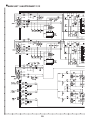
BLOCK DIAGRAM .......................................... 88
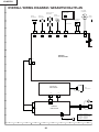
OVERALL WIRING DIAGRAM ....................... 90
WAVEFORMS ................................................. 92
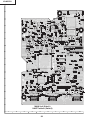
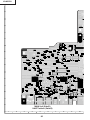
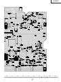
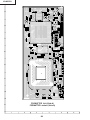
PRINTED WIRING BOARD ASSEMBLIES .... 93
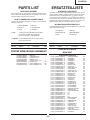
PARTS LIST
Ë ELECTRICAL PARTS ............................... 101
Ë CABINET AND MECHANICAL PARTS .... 116
Ë ACCESSORIES PARTS ........................... 120
Ë PACKING PARTS ..................................... 120
• PACKING OF THE SET ................................ 121
• SCHEMATIC DIAGRAM ........................ D1-D39
INHALT
Seite
Seite
• SPEZIFIKATIONEN ........................................ 47
• HINWEISE FÜR DAS
WARTUNGSPERSONAL ................................ 48
• BEDIENUNGSANLEITUNG ............................ 50
• ABMESSUNGEN ............................................ 56
• ENTFERNEN DER HAUPTTEILE .................. 57
• RÜCKSTELLEN DES
LAMPENBETRIEBSZEIT-TIMERS ................. 61
• BESCHREIBUNG DER OPTIK-EINHEIT ....... 63
• ELEKTRISCHE EINSTELLUNG ..................... 65
• FEHLERSUCHTABELLE ................................ 72
• CHASSIS-ANORDNUNG ............................... 86
•
•
•
•
•
•
BLOCKSCHALTBILD ...................................... 88
GESAMTSCHALTPLAN .................................. 90
BESCHREIBUNG DES SCHEMATISCHEN
WELLENFORMEN .......................................... 92
LEITERPLATTENEINHEITEN ........................ 93
ERSATZTEILLISTE
Ë ELEKTRISCHE BAUTEILE ....................... 101
Ë GEHÄUSE UND MECHANISCHE
BAUTEILE ................................................. 116
Ë ZUBEHÖRTEILE ....................................... 120
Ë VERPACKUNGSTEILE ............................. 120
• VERPACKEN DES GERÄTS ........................ 121
• SCHEMATISCHER SCHALTPLAN ........ D1-D39
2
XG-MB70X
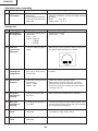
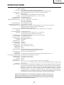
SPECIFICATIONS
Product type
Model
Video system
Display method
DMD panel
Lens
Projection lamp
Component input (INPUT 1/2)/
output (OUTPUT) signal
Multimedia Projector
XG-MB70X
NTSC3.58/NTSC4.43/PAL/PAL-M/PAL-N/PAL-60/SECAM/
DTV480I/DTV480P/DTV540P/DTV576I/DTV576P/DTV720P/DTV1035I/DTV1080I
Single Chip Digital Micromirror DeviceTM (DMDTM) by Texas Instruments
Panel size: 0.7"
No. of dots: 786,432 dots (1,024 [H] ✕ 768 [V])
1.5 ✕ electric zoom / focus lens, F2.0–2.5, f = 21.3–31.6 mm
275 W DC lamp
15-pin mini D-sub connector
Y: 1.0 Vp-p, sync negative, 75 Ω terminated
PB: 0.7 Vp-p, 75 Ω terminated
PR: 0.7 Vp-p, 75 Ω terminated
Horizontal resolution 750 TV lines (DTV720P)
Computer RGB input (INPUT 1/2)/ 15-pin mini D-sub connector
output (OUTPUT) signal RGB separate/sync on green type analog input: 0–0.7 Vp-p, positive, 75 Ω terminated
HORIZONTAL SYNC. SIGNAL: TTL level (positive/negative)
VERTICAL SYNC. SIGNAL: Same as above
Video input signal RCA connector: VIDEO, composite video, 1.0 Vp-p, sync negative, 75 Ω terminated
(INPUT 3) 4-pin mini DIN connector
S-video input signal Y (luminance signal): 1.0 Vp-p, sync negative, 75 Ω terminated
(INPUT 4) C (chrominance signal): Burst 0.286 Vp-p, 75 Ω terminated
Audio input signal ø3.5 mm minijack: AUDIO, 0.5 Vrms, more than 22 kΩ (stereo)
USB terminal 4-pin B-type USB female connector
RS-232C terminal 9-pin mini DIN connector
LAN terminal 8-pin RJ-45 modular connector
Pixel clock 12–108 MHz
Vertical frequency 43–85 Hz
Horizontal frequency 15–70 kHz
Audio output 2.0 W (monaural)
Speaker system 4.0 cm ✕ 2.85 cm oval ✕1 16 Ω
Rated voltage AC 100–240 V
Input current 3.9 A
Rated frequency 50/60 Hz
Power consumption 370 W (Standard mode)/320 W (Eco mode) with AC 100 V
350 W (Standard mode)/300 W (Eco mode) with AC 240 V
Power consumption (standby) 6 W (AC 100 V) – 8 W (AC 240 V)
Heat dissipation 1,390 BTU/hour (Standard mode)/1,200 BTU/hour (Eco mode) with AC 100 V
1,315 BTU/hour (Standard mode)/1,130 BTU/hour (Eco mode) with AC 240 V
Operating temperature 41°F to 104°F (+5°C to +40°C)
Storage temperature –4°F to 140°F (–20°C to +60°C)
Cabinet Plastic
I/R carrier frequency 38 kHz
Dimensions (approx.) 12 7/32" ✕ 3 33/64" ✕ 11 7/64" (310 (W) ✕ 89 (H) ✕ 282 (D) mm) (main body only)
12 7/32" ✕ 4 7/64" ✕ 11 5/16" (310 (W) ✕ 104 (H) ✕ 287 (D) mm) (including adjustment foot and projecting parts)
Weight (approx.) 9.1 lbs. (4.1 kg)
Replacement parts Lamp unit (Lamp/cage module) (AN-MB70LP), Remote control (RRMCGA313WJSA), Power cord for U.S.,
Canada, etc. (QACCDA010WJPZ), Power cord for Europe, except U.K. (QACCVA011WJPZ), Power cord for
U.K., Hong Kong and Singapore (QACCBA036WJPZ), Power cord for Australia, New Zealand and Oceania
(QACCLA018WJPZ), RGB cable (QCNWGA045WJPZ), USB cable (QCNWGA014WJPZ), Storage case
(GCASNA014WJSA), Lens cap (RCAPHA021WJSA), Projector manual and technical reference CD-ROM
(UDSKAA052WJZZ), “QUICK GUIDE” label (TLABZA717WJZZ), Operation manual (TINS-B416WJZZ)
As a part of policy of continuous improvement, SHARP reserves the right to make design and
specification changes for product improvement without prior notice. The performance specification figures indicated are nominal values of production units. There may be some deviations from
these values in individual units.
3
XG-MB70X
IMPORTANT SERVICE SAFETY NOTES (for USA)
Ë Service work should be performed only by qualified service technicians who are
thoroughly familiar with all safety checks and servicing guidelines as follows:
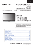
» Use an AC voltmeter with sensitivity of 5000 ohm per
volt., or higher, sensitivity to measure the AC voltage
drop across the resistor (See Diagram).
» All checks must be repeated with the AC plug
connection reversed. (If necessary, a non-polarized
adapter plug must be used only for the purpose of
completing these checks.)
Any reading of 0.3 volts RMS (this corresponds to 0.2
milliamp. AC.) or more is excessive and indicates a
potential shock hazard which must be corrected before
returning the unit to the owner.
WARNING
1. For continued safety, no modification of any circuit
should be attempted.
2. Disconnect AC power before servicing.
BEFORE RETURNING THE PROJECTOR:
(Fire & Shock Hazard)
Before returning the projector to the user, perform
the following safety checks:
1. Inspect lead wires are not pinched between the chassis
and other metal parts of the projector.
2. Inspect all protective devices such as non-metallic
control knobs, insulating materials, cabinet backs,
adjustment and compartment covers or shields,
isolation resistor-capacity networks, mechanical
insulators, etc.
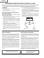
3. To be sure that no shock hazard exists, check for
current leakage in the following manner:
» Plug the AC cord directly into a 120-volt AC outlet, (Do
not use an isolation transformer for this test).
» Using two clip leads, connect a 1.5k ohm, 10 watt
resistor paralleled by a 0.15µF capacitor in parallel
between all exposed metal cabinet parts and earth
ground.
DVM
AC SCALE
1.5k ohm
10W
0.15 µF
TEST PROBE
TO EXPOSED
METAL PARTS
CONNECT TO
KNOWN EARTH
GROUND
12345678901234567890123456789012123456789012345678901234567890121234567890123456789012345678901212
12345678901234567890123456789012123456789012345678901234567890121234567890123456789012345678901212
12345678901234567890123456789012123456789012345678901234567890121234567890123456789012345678901212
SAFETY NOTICE
AVIS POUR LA SECURITE
Many electrical and mechanical parts in DMD™
Projector have special safety-related characteristics.
These characteristics are often not evident from visual
inspection, nor can protection afforded by them be
necessarily increased by using replacement components
rated for higher voltage, wattage, etc.
Replacement parts which have these special safety
characteristics are identified in this manual; electrical
components having such features are identified by “å”
and shaded areas in the Replacement Parts Lists and
Schematic Diagrams. For continued protection,
replacement parts must be identical to those used in
the original circuit. The use of a substitute replacement
parts which do not have the same safety characteristics
as the factory recommended replacement parts shown
in this service manual, may create shock, fire or other
hazards.
De nombreuses pièces, électriques et mécaniques, dans
les projecteur à DMD™ présentent des caractéristiques
spéciales relatives à la sécurité, qui ne sont souvent pas
évidentes à vue.
Le degré de protection ne peut pas être nécessairement
augmentée en utilisant des pièces de remplacement
étalonnées pour haute tension, puissance, etc.
Les pièces de remplacement qui présentent ces
caractéristiques sont identifiées dans ce manuel;
les pièces électriques qui présentent ces particularités
sont identifiées par la marque “å” et hachurées dans la
liste des pièces de remplacement et les diagrammes
schématiques. Pour assurer la protection, ces pièces
doivent être identiques à celles utilisées dans le circuit
d’origine. L’utilisation de pièces qui n’ont pas les mêmes
caractéristiques que les pièces recommandées par l’usine,
indiquées dans ce manuel, peut provoquer des
électrocutions, incendies ou autres accidents.
WARNING: The bimetallic component has the primary
conductive side exposed. Be very careful in
handling this component when the power is on.
AVERTISSEMENT: La composante bimétallique dispose du
conducteur primaire dénudé. Faire attention
lors de la manipulation de cette
composante sous tension.
12345678901234567890123456789012123456789012345678901234567890121234567890123456789012345678901212
12345678901234567890123456789012123456789012345678901234567890121234567890123456789012345678901212
12345678901234567890123456789012123456789012345678901234567890121234567890123456789012345678901212
4
XG-MB70X
PRECAUTIONS A PRENDRE LORS DE LA REPARATION
Ë
Ne peut effectuer la réparation qu' un technicien spécialisé qui s'est parfaitement
accoutumé à toute vérification de sécurité et aux conseils suivants.
AVERTISSEMENT
conduite électrique ou une prise de terre branchée à la
terre.
• Utiliser un voltmètre CA d'une sensibilité d'au moins
5000Ω/V pour mesurer la chute de tension en travers
de la résistance.
• Toucher avec la sonde d'essai les pièces métalliques
exposées qui présentent une voie de retour au châssis
(antenne, coffret métallique, tête des vis, arbres de
commande et des boutons, écusson, etc.) et mesurer la
chute de tension CA en-travers de la résistance. Toutes
les vérifications doivent être refaites après avoir inversé
la fiche du cordon d'alimentation. (Si nécessaire, une
prise d'adpatation non polarisée peut être utilisée dans
le but de terminer ces vérifications.)
Tous les courants mesurés ne doivent pas dépasser 0.5
mA.
Dans le cas contraire, il y a une possibilité de choc
électrique qui doit être supprimée avant de rendre le
récepteur au client.
1. N'entreprendre aucune modification de tout circuit.
C'est dangereux.
2. Débrancher le récepteur avant toute réparation.
PRECAUTION: POUR LA
PROTECTION CONTINUE CONTRE
LES RISQUES D'INCENDIE,
REMPLACER LE FUSIBLE
CÔTÉ LCD : F701 (6.3A, AC250V)
VERIFICATIONS CONTRE L'INCEN-DIE ET
LE CHOC ELECTRIQUE
Avant de rendre le récepteur à l'utilisateur, effectuer
les vérifications suivantes.
1. Inspecter tous les faisceaux de câbles pour s'assurer
que les fils ne soient pas pincés ou qu'un outil ne soit
pas placé entre le châssis et les autres pièces
métalliques du récepteur.
2. Inspecter tous les dispositifs de protection comme les
boutons de commande non-métalliques, les isolants, le
dos du coffret, les couvercles ou blindages de réglage
et de compartiment, les réseaux de résistance-capacité,
les isolateurs mécaniques, etc.
3. S'assurer qu'il n'y ait pas de danger d'électrocution en
vérifiant la fuite de courant, de la facon suivante:
• Brancher le cordon d'alimentation directem-ent à une
prise de courant de 110-240V. (Ne pas utiliser de
transformateur d'isolation pour cet essai).
• A l'aide de deux fils à pinces, brancher une résistance
de 1.5 kΩ 10 watts en parallèle avec un condensateur
de 0.15µF en série avec toutes les pièces métalliques
exposées du coffret et une terre connue comme une
DVM
ECHELLE CA
1.5k ohm
10W
0.15 µF
SONDE D'ESSAI
AUX PIECES
METALLIQUES
EXPOSEES
BRANCHER A UNE
TERRE CONNUE
12345678901234567890123456789012123456789012345678901234567890121234567890123456789012345678901212
12345678901234567890123456789012123456789012345678901234567890121234567890123456789012345678901212
12345678901234567890123456789012123456789012345678901234567890121234567890123456789012345678901212
AVIS POUR LA SECURITE
De nombreuses pièces, électriques et mécaniques, dans les téléviseur ACL présentent des caractéristiques spéciales
relatives à la sécurité, qui ne sont souvent pas évidentes à vue. Le degré de protection ne peut pas être nécessairement
augmentée en utilisant des pièces de remplacement étalonnées pour haute tension, puissance, etc.
Les pièces de remplacement qui présentent ces caractéristiques sont identifiées dans ce manuel; les pièces électriques
qui présentent ces particularités sont identifiées par la marque " å " et hachurées dans la liste des pièces de
remplacement et les diagrammes schématiques.
Pour assurer la protection, ces pièces doivent être identiques à celles utilisées dans le circuit d'origine. L'utilisation
de pièces qui n'ont pas les mêmes caractéristiques que les pièces recommandées par l'usine, indiquées dans ce
manuel, peut provoquer des électrocutions, incendies, radiations X ou autres accidents.
12345678901234567890123456789012123456789012345678901234567890121234567890123456789012345678901212
12345678901234567890123456789012123456789012345678901234567890121234567890123456789012345678901212
12345678901234567890123456789012123456789012345678901234567890121234567890123456789012345678901212
12345678901234567890123456789012123456789012345678901234567890121234567890123456789012345678901212
5
XG-MB70X
NOTE TO SERVICE
NOTE POUR LE PERSONNEL
PERSONNEL
D’ENTRETIEN
123456789012345678901234567890121234567890123456 123456789012345678901234567890121234567890123456
123456789012345678901234567890121234567890123456
123456789012345678901234567890121234567890123456
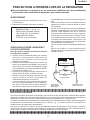
UV-RADIATION PRECAUTION
123456789012345678901234567890121234567890123456
123456789012345678901234567890121234567890123456
PRECAUTION POUR LES RADIATIONS UV
123456789012345678901234567890121234567890123456
123456789012345678901234567890121234567890123456
The light source, UHP lamp, in the LCD projector
emits small amounts of UV-Radiation.
La source de lumière, la lampe UHP, dans le projecteur
LCD émet de petites quantités de radiation UV.
AVOID DIRECT EYE AND SKIN EXPOSURE.
EVITEZ TOUTE EXPOSITION DIRECTE DES
YEUX ET DE LA PEAU.
To ensure safety please adhere to the following:
Pour votre sécurité, nous vous prions de respecter
les points suivants:
1. Toujours porter des lunettes de soleil lors d’un entretien
du projecteur
avec la lampe allumée
et le haut du coffret retiré.
1. Be sure to wear sun-glasses when servicing the
projector with the lamp
turned “on” and the top
enclosure removed.
2. Ne pas faire fonctionner la lampe à l’extérieur du boîtier
de lampe.
2. Do not operate the lamp outside of the lamp housing.
3. Ne pas faire fonctionner plus de 2 heures avec le coffret
retiré.
3. Do not operate for more than 2 hours with the enclosure
removed.
Précautions pour les radiations UV
et la lampe moyenne pression
UV-Radiation and Medium Pressure
Lamp Precautions
1. Toujours débrancher la fiche AC lors du remplacement
de la lampe.
2. Laisser l’unité refroidir pendant une heure avant de
procéder à l’entretien.
3. Ne remplacer qu’avec une lampe du même type. Type
AN-MB70LP, caractéristique 275W.
4. La lampe émet de petites quantités de radiation UVéviter tout contact direct avec les yeux.
5. La lampe moyenne pression implique un risque
d’explosion. Toujours suivre les instructions
d’installation décrites ci-dessous et manipuler la lampe
avec soin.
1. Be sure to disconnect the AC plug when replacing the
lamp.
2. Allow one hour for the unit to cool down before
servicing.
3. Replace only with same type lamp. Type AN-MB70LP
rated 275W.
4. The lamp emits small amounts of UV-Radiation, avoid
direct-eye contact.
5. The medium pressure lamp involves a risk of explosion.
Be sure to follow installation instructions described
below and handle the lamp with care.
6
XG-MB70X
123456789012345678901234567890121234567890123456
123456789012345678901234567890121234567890123456
123456789012345678901234567890121234567890123456
123456789012345678901234567890121234567890123456
123456789012345678901234567890121234567890123456
123456789012345678901234567890121234567890123456
UV-RADIATION PRECAUTION (Continued)
123456789012345678901234567890121234567890123456
123456789012345678901234567890121234567890123456
123456789012345678901234567890121234567890123456
PRECAUTION POUR LES RADIATIONS UV (Suite)
123456789012345678901234567890121234567890123456
123456789012345678901234567890121234567890123456
123456789012345678901234567890121234567890123456
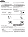
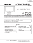
Lamp Replacement
Remplacement de la lampe
Note:
Remarque:
Since the lamp reaches a very high temperature during
units operation replacement of the lamp should be
done at least one hour after the power has been turned
off. (to allow the lamp to cool off.)
Installing the new lamp, make sure not to touch the
lamp (bulb) replace the lamp by holding its reflector
2.
[Use original replacement only.]
Comme la lampe devient très chaude pendant le
fonctionnement de l’unité, son remplacement ne doit
être effectué au moins une heure après avoir coupé
l’alimentation (pour permettre à la lampe de refroidir).
En installant la nouvelle lampe, s’assurer de ne pas
toucher la lampe (ampoule). Remplacer la lampe en
tenant son réflecteur 2.
[N’utiliser qu’un remplacement d’origine.]
1 Lampe
1 Lamp
2 Reflecteur
2 Reflector
DANGER ! –– Never turn the power on without the
lamp to avoid electric-shock or damage of the devices
since the stabilizer generates high voltages at its start.
DANGER ! –– Ne jamais mettre sous tension sans la
lampe pour éviter un choc électrique ou des
dommages des appareils car le stabilisateur génère
de hautes tensions à sa mise en route.
Since small amounts of UV-radiation are emitted
from an opening between the exhaust fans, it is recommended to place the cap of the optional lens on
the opening during servicing to avoid eye and skin
exposure.
Comme de petites quantités de radiation UV sont
émises par une ouverture entre les ventilateurs aspirants, il est recommandé de placer le capuchon de
l’optique optionnelle sur l’ouverture pendant l’entretien
pour éviter une exposition des yeux et la peau.
7
XG-MB70X
WARNING:
High brightness light source, do not stare into the beam of light, or view directly. Be especially
careful that children do not stare directly in to the beam of light.
WARNING:
TO REDUCE THE RISK OF FIRE OR ELECTRIC SHOCK, DO NOT EXPOSE THIS UNIT TO
MOISTURE OR WET LOCATIONS.
CAUTION
The lighting flash with arrowhead within a
triangle is intended to tell the user that
parts inside the product are risk of electric
shock to persons.
RISK OF ELECTRIC SHOCK.
DO NOT REMOVE SCREWS
EXCEPT SPECIFIED USER
SERVICE SCREW.
CAUTION: TO REDUCE THE RISK OF ELECTRIC SHOCK,
DO NOT REMOVE CABINET.
NO USER-SERVICEABLE PARTS EXCEPT LAMP UNIT.
REFER SERVICING TO QUALIFIED SERVICE
PERSONNEL.
The exclamation point within a triangle is
intended to tell the user that important
operating and servicing instructions are in
the manual with the projector.
CAUTION
(POWER Unit)
6.3A 250V
For continued
protection against a
risk of fire, replace
only with same type
6.3A, AC250V fuse.
(F701)
12345678901234567890123456789012123456789012345678901234567890121234567890123456789012345678901212
12345678901234567890123456789012123456789012345678901234567890121234567890123456789012345678901212
AVERTISSEMENT: Source lumineuse de grande intensité. Ne pas fixer le faisceau lumineux ou le regarder
directement. Veiller particulièrement à éviter que les enfants ne fixent directement le
faisceau lumineux.
AVERTISSEMENT: AFIN D’EVITER TOUT RISQUE D’INCENDIE OU D’ELECTROCUTION, NE PAS PLACER
CET APPAREIL DANS UN ENDROIT HUMIDE OU MOUILLE.
ATTENTION
L’éclair terminé d’une flèche à l’intérieur
d’un triangle indique à l’utilisateur que les
pi‘eces se trouvant dans l’appareil sont
susceptibles de provoquer une décharge
électrique.
RISQUE
D’ÉLECTROCUTION. NE
PASR ETIRER LES VIS Á
L’EXCEPTION DE LA VIS DE
REPARATION UTILISATEUR
SPECIFIEES
Le point d’exclamation à l’intérieur d’un
triangle indique à l’utilisateur que les
instructions de fonctionnement et
d’entretien sont détaillées dans les
documents fournis avec le projecteur.
ATTENTION: POUR EVITER TOUT RISQUE
D’ELECTROCUTION, NE PAS RETIRER LE CAPOT.
AUCUNE DES PIECES INTERIEURES N’EST REPARABLE
PAR L’UTILISATEUR, A L’EXCEPTION DE L’UNITE DE
LAMPE. POUR TOUTE REPARATION, S’ADRESSER A UN
TECHNICIEN D’ENTRETIEN QUALIFIE.
PRECAUTION
(Unité de PUTSSANCE)
Pour une protection
continue contre un
risques d’incendie, ne
remplacer qu’avec un
fusible 6.3A,AC250V
6.3A 250V du même type.
(F701)
8
XG-MB70X
Precautions for using lead-free solder
1 Employing lead-free solder
"PWBs" of this model employs lead-free solder. The LF symbol indicates lead-free solder, and is attached on the
PWBs and service manuals. The alphabetical character following LF shows the type of lead-free solder.
Example:
LFa
Indicates lead-free solder of tin, silver and copper.
2 Using lead-free wire solder
When fixing the PWB soldered with the lead-free solder, apply lead-free wire solder. Repairing with conventional
lead wire solder may cause damage or accident due to cracks.
As the melting point of lead-free solder (Sn-Ag-Cu) is higher than the lead wire solder by 40°C, we recommend you
to use a dedicated soldering bit, if you are not familiar with how to obtain lead-free wire solder or soldering bit,
contact our service station or service branch in your area.
3 Soldering
As the melting point of lead-free solder (Sn-Ag-Cu) is about 220°C which is higher than the conventional lead solder
by 40°C, and as it has poor solder wettability, you may be apt to keep the soldering bit in contact with the PWB for
extended period of time. However, since the land may be peeled off or the maximum heat-resistance temperature of
parts may be exceeded, remove the bit from the PWB as soon as you confirm the steady soldering condition.
Lead-free solder contains more tin, and the end of the soldering bit may be easily corroded. Make sure to turn on
and off the power of the bit as required.
If a different type of solder stays on the tip of the soldering bit, it is alloyed with lead-free solder. Clean the bit after
every use of it.
When the tip of the soldering bit is blackened during use, file it with steel wool or fine sandpaper.
Be careful when replacing parts with polarity indication on the PWB silk.
Lead-free wire solder for servicing
Part No.
ZHNDAi123250E
ZHNDAi126500E
ZHNDAi12801KE
★
J
J
J
Description
φ0.3mm
250g(1roll)
φ0.6mm
500g(1roll)
φ1.0mm
1kg(1roll)
9
Code
BL
BK
BM
XG-MB70X
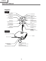
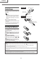
Operation Manual
Projector
Top View
ON button
For turning the power on.
Power indicator
STANDBY button
For putting the projector into
standby mode.
Lamp indicator
Temperature warning
indicator
Volume buttons
KEYSTONE button
For entering the Keystone
Correction mode.
For adjusting the speaker
sound level.
ZOOM/FOCUS button
ENTER button
For adjusting the projected
image size or adjusting the
focus.
For setting items selected
or adjusted on the menu.
AUTO SYNC button
INPUT buttons
For automatically
adjusting images when
connected to a computer.
For switching input mode
1, 2, 3 or 4.
AUTO FOCUS button
MENU button
For adjusting the focus
automatically.
For displaying adjustment
and setting screens.
Adjustment buttons
('/"/\/|)
For selecting menu items and
other settings.
Front View
Remote control sensor
Speaker
Auto focus sensor
Front adjustment foot
(on the bottom of
the projector)
HEIGHT ADJUST button
• Attaching the lens cap
Push the lens cap on until it clicks
into position.
• Removing the lens cap
Pull the lens cap directly outward.
10
XG-MB70X
About the Indicators on the Projector
Power indicator
Red on ... Normal (Standby)
Green on ... Normal (Power on)
Lamp indicator
Green on ... Normal
Green blinks ... The lamp is warming up or shutting down.
Red on ... The lamp has been shut down abnormally or
needs to be changed.
Temperature warning indicator
Off ... Normal
Red on ... The internal temperature is abnormally high.
When Attaching the “QUICK GUIDE” Label
Attaching the “QUICK GUIDE” Label (supplied) on the
projector will help you check the setup procedure.
Ensure to attach the “QUICK GUIDE” Label on the top
cabinet of the projector as shown in the drawing on the
right. Do not attach the “QUICK GUIDE” label anywhere
else to avoid blocking an air intake or exhaust vent.
11
“QUICK GUIDE”
Label
XG-MB70X
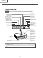
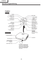
Projector (Rear View)
Terminals
Refer to “INPUT/OUTPUT Terminals and Connectable Main Equipment”
AUDIO OUTPUT terminal
INPUT 3 terminal
Audio output terminal of
equipment connected to the
AUDIO INPUT terminal.
Terminal for connecting
video equipment.
INPUT 4 terminal
Terminal for connecting
video equipment with an
S-video terminal.
OUTPUT (INPUT 1, 2) terminal
Shared computer RGB and component
signals output terminal for INPUT 1 and 2.
Terminal for connecting a monitor.
AUDIO INPUT 3, 4 terminal
Shared audio input terminal
for INPUT 3 and 4.
AUDIO INPUT 1, 2 terminal
Shared audio input terminal
for INPUT 1 and 2.
USB terminal
INPUT 2 terminal
RS-232C terminal
Terminal for computer RGB
and component signals.
Terminal for controlling
the projector using a computer.
INPUT 1 terminal
LAN terminal
Terminal for computer RGB
and component signals.
Terminal for controlling the
projector using a computer via
network.
Exhaust vent
The speed and pitch of
the cooling fan may
change during operation
in response to internal
temperature changes.
This is normal operation
and does not indicate a
malfunction.
Remote control sensor
Intake vent
Kensington Security
Standard connector
AC socket
Connect the supplied
Power cord.
Rear adjustment feet
Using the Kensington Lock
• This projector has a Kensington Security Standard connector for use with a Kensington MicroSaver Security
System. Refer to the information that came with the system for instructions on how to use it to secure the
projector.
12
XG-MB70X
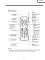
Remote Control
ON button
For turning the power on.
STANDBY button
AUTO FOCUS button
For putting the projector into
standby mode.
For adjusting the focus
automatically.
FOCUS buttons
For bringing the projected image
into focus.
ZOOM buttons
For adjusting the projected
image size.
IRIS button
For switching HIGH BRIGHTNESS
MODE or HIGH CONTRAST MODE .
KEYSTONE button
MENU button
For entering the Keystone
Correction mode.
For displaying adjustment and
setting screens.
MOUSE/Adjustment button
('/"/\/|)
L-CLICK/ENTER button
• For moving the computer cursor
when connecting the projector
USB terminal to the computer
with USB cable.
• For selecting menu items.
• For the Left click when
connecting the projector
USB terminal to the
computer with USB cable.
• For setting items selected
or adjusted on the menu.
R-CLICK/UNDO button
FREEZE button
• For the Right click when
connecting the projector USB
terminal to the computer with
USB cable.
• For undoing an operation or
returning to the previous display.
For freezing images.
ENLARGE (Enlarge/Reduce)
buttons
AV MUTE button
For temporarily displaying the
black screen and turning off the
sound.
For enlarging/reducing part of the
image.
Volume buttons
INPUT 1, 2, 3 and 4 buttons
For adjusting the speaker sound
level.
For switching to the respective
input modes.
PICTURE MODE button
For switching the picture mode.
RESIZE button
AUTO SYNC button
For switching the screen size
(NORMAL, BORDER, etc.).
For automatically adjusting images
when connected to a computer.
Note
• All the buttons on the remote control, except the MOUSE/Adjustment button, are made of luminous
material that is visible in the dark. Visibility will diminish over time. Exposure to light will recharge the
luminous buttons.
13
XG-MB70X
Front View
Remote control sensor
Usable Range
30°
The remote control can be used to control
the projector within the ranges shown in the
illustration.
30°
Remote control
signal transmitters
30°
Note
23’ (7 m)
Remote control
• The signal from the remote control can be
reflected off a screen for easy operation.
However, the effective distance of the signal may differ depending on the screen
material.
Rear View
Remote control sensor
30°
When using the remote control:
30°
• Ensure not to drop, expose to moisture or high
temperature.
• The remote control may malfunction under a
fluorescent lamp. In this case, move the projector away from the fluorescent lamp.
23’ (7 m)
30°
Remote control
signal transmitters
Remote control
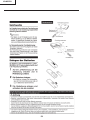
Inserting the Batteries
The batteries (two R-03 batteries (“AAA”
size, UM/SUM-4, HP-16 or similar)) are supplied in the package.
1
Press the mark on the cover and
slide it in the direction of the arrow.
2
Insert the batteries.
• Insert the batteries making sure the poand
larities correctly match the
marks inside the battery compartment.
3
Attach the cover and slide it until it clicks into place.
Incorrect use of the batteries may cause them to leak or explode. Please follow the precautions below.
Caution
• Insert the batteries making sure the polarities correctly match the
and
marks inside the battery compartment.
• Batteries of different types have different properties, therefore do not mix batteries of different types.
• Do not mix new and old batteries.
This may shorten the life of new batteries or may cause old batteries to leak.
• Remove the batteries from the remote control once they have run out, as leaving them in can cause them to leak.
Battery fluid from leaked batteries is harmful to skin, therefore ensure to first wipe them and then remove them
using a cloth.
• The batteries included with this projector may run down in a short period, depending on how they are kept.
Ensure to replace them as soon as possible with new batteries.
• Remove the batteries from the remote control if you will not be using the remote control for a long time.
14
XG-MB70X
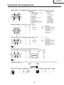
Connection Pin Assignments
INPUT 1/INPUT 2 and OUTPUT RGB Signal Terminal: 15-pin Mini D-sub female connector
RGB Input
11
15
1
6
5
10
1.
2.
3.
4.
5.
6.
7.
8.
9.
10.
11.
12.
13.
14.
15.
Component Input
Video input (red)
Video input (green/sync on green)
Video input (blue)
Not connected
Not connected
Earth (red)
Earth (green/sync on green)
Earth (blue)
Not connected
GND
Not connected
Bi-directional data
Horizontal sync signal: TTL level
Vertical sync signal: TTL level
Data clock
1.
2.
3.
4.
5.
6.
7.
8.
9.
10.
11.
12.
13.
14.
15.
PR (CR)
Y
PB (CB)
Not connected
Not connected
Earth (PR)
Earth (Y)
Earth (PB)
Not connected
Not connected
Not connected
Not connected
Not connected
Not connected
Not connected
RS-232C Terminal: 9-pin Mini DIN female connector
1
2
4
5
6
3
Pin No.
1
2
3
4
5
6
7
8
9
Signal
Name
I/O
RD
SD
Receive Data
Send Data
SG
Signal Ground
Reference
Not connected
Connected to internal circuit
Connected to internal circuit
Not connected
Connected to internal circuit
Not connected
Connected to Pin 8
Connected to Pin 7
Not connected
Input
Output
RS
CS
9
7
8
DIN-D-sub RS-232C adaptor: 9-pin D-sub male connector
1
6
5
Pin No.
1
2
3
4
5
6
7
8
9
9
Signal
Name
I/O
RD
SD
Receive Data
Send Data
SG
Signal Ground
Reference
Not connected
Connected to internal circuit
Connected to internal circuit
Not connected
Connected to internal circuit
Not connected
Connected to internal circuit
Connected to internal circuit
Not connected
Input
Output
RS
CS
Note
Pin 8 (CS) and Pin 7 (RS) are short circuited inside the projector.
RS-232C Cable recommended connection: 9-pin D-sub female connector
5
9
Pin No.
1
2
3
4
5
6
7
8
9
1
6
Signal
CD
RD
SD
ER
SG
DR
RS
CS
CI
Pin No.
1
2
3
4
5
6
7
8
9
Signal
CD
RD
SD
ER
SG
DR
RS
CS
CI
Note
Depending on the controlling device used, it may be necessary to connect Pin 4 and Pin 6 on the controlling
device (e.g. computer).
Computer
Pin No.
4
5
6
Projector
Pin No.
4
5
6
USB Terminal: 4-pin B-type USB female connector
4 3
Pin No.
1
2
3
4
Signal
VCC
USB–
USB+
SG
LAN Terminal : 8-pin RJ-45 modular connector
Name
USB power
USB data–
USB data+
GND
8...1
1 2
15
Pin No.
1
2
3
4
Signal
TX+
TX–
RX+
Pin No.
5
6
7
8
Signal
RX–
XG-MB70X
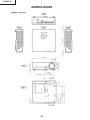
Side View
Top View
Side View
1/16
Rear View
9
/64 (3.25)
11 7/64 (282)
Units: inches(mm)
(1.5)
DIMENSIONS
12 7/32 (310)
2 3/16
(55.5)
3 33/64 (89)
/64 (5)
Front View
1 59/64
(48.5)
2 11/64 (55.05)
13
3 15/16 (99.95)
5 7/64 (129.5)
5 7/64 (129.5)
7
1 5/32 1 /32
(29.1) (30.9)
M4
M4
9
5/8
/16 (14)
(15.5)
1 3/4
1 7/32
(44.1) (30.9)
16
8 7/8 (225.3)
M4
8 9/32 (210.3)
M4
4 3/16 (106.3)
Bottom View
XG-MB70X
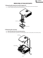
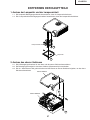
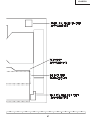
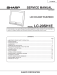
REMOVING OF MAJOR PARTS
1. Removing the lamp door and the lamp unit
1-1. Loosen the lamp door fixing screw, slide the lamp door in allow direction and lift off the lamp door.
1-2. Loosen 2 lamp unit fixing screws and lift off the lamp unit.
Lamp Unit
1-3
Lamp Door
1-2
2. Removing the top body
2-1. Remove 6 fixing screws for the top and bottom bodies.
2-2. Remove the fixing screw for the top body (terminal side).
2-3. Press and hold the areas (marked with *) and disengage the claws on the top body to remove the top body.
Top Body
2-2
Bottom Body
2-1
17
XG-MB70X
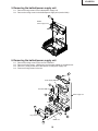
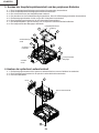
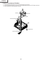
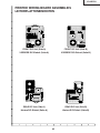
3. Removing the main PWB unit and the peripheral units
3-1.
3-2.
3-3.
3-4.
3-5.
3-6.
3-7.
3-8.
Remove 2 main PWB fixing screws (terminal side).
Remove 8 main PWB fixing screws.
Remove 14 connectors from the main PWB.
Pull out the switch bracket connector and remove 3 fixing screws.
Remove the fixing screw for the front R/C PWB.
Remove 2 fixing screws for the A/F holder unit.
Lift off the main PWB in an oblique direction from the optical mechanism unit side.
Remove the speaker holder ass’y.
Main PWB Unit
3-3
[RA]
[FC]
[FA]
[FB]
[TO]
Earth Lead Wire
3-2
3-4
[TF]
Switch Bracket Unit
[DD]
[SC5001]
[CW] [FD]
[AZ]
[AI] [SO]
3-5
[EA]
3-7
Front R/C PWB
3-1
3-8
3-6
Speaker
Holder
Ass’y
A/F Holder unit
4. Removing the optical mechanism unit
4-1. Remove the fixing screw for the optical mechanism unit from the bottom body.
4-2. Remove 5 fixing screws for the optical mechanism unit.
4-3. Remove the duct.
4-1
Duct
4-3
Optical Mechanism Unit
4-2
18
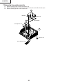
XG-MB70X
5. Removing the ballast/power supply unit
5-1. Remove 2 fixing screws for the ballast/power supply unit.
5-2. Remove the fixing screw for the ballast/power supply unit (terminal side).
5-1
Ballast/
Power supply Unit
5-2
6. Removing the ballast/power supply unit
6-1.
6-2.
6-3.
6-4.
Remove the fixing screw for the rear R/C PWB unit.
Remove 4 fixing screws, 4 WH bosses and the edge saddle for the ballast unit.
Remove 11 fixing screws and 5 WH bosses for the power supply unit.
Remove 4 fixing screws for the fan.
6-3
Power Supply PWB Unit
6-1
6-3
Rear R/C PWB Unit
6-3
Power Supply Unit
6-4
6-2
6-3
Fan
6-2
6-3
Edge saddle
6-3
Ballast Unit
6-2
19
XG-MB70X
7. Removing the peripheral units
7-1. Remove 4 fixing screws for the front adjuster unit.
7-2. Remove 8 bracket fixing screws and remove the bracket A, bracket B and earth plate.
7-3. Remove 2 fixing cap nuts for the adjuster unit.
7-2
Bracket A
Bracket B
Earth Plate
7-1
Front Adjuster Unit
7-3
Adjuster Unit
Front Adjuster Unit
20
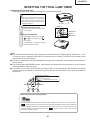
XG-MB70X
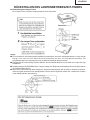
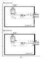
RESETTING THE TOTAL LAMP TIMER
● Resetting the total lamp timer
When replacing the lamp, reset the total lamp timer in the procedure below.
Info
• Make sure to reset the lamp timer only
when replacing the lamp. If you reset the
lamp timer and continue to use the same
lamp, this may cause the lamp to become
damaged or explode.
1
AC socket
ON button
Connect the power cord.
• Plug the power cord into the AC socket
of the projector.
ENTER button
2
" button
Reset the lamp timer.
MENU button
• While simultaneously holding down ",
and
on the projector, press
on
the projector.
• LAMP 0000H is displayed, indicating
that the lamp timer is reset.
Lamp
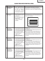
■ It is recommended that the lamp (sold separately) be replaced when the remaining lamp life becomes 5% or less,
or when you notice a significant deterioration in the picture and color quality. The lamp life (percentage) can be
checked with the on-screen display.
■ Purchase a replacement lamp of type AN-MB70LP from your place of purchase, nearest Sharp Projector Dealer or
Service Center.
■ The warning lights (ON/STANDBY button, lamp indicator and temperature warning indicator) on the projector
indicate problems inside the projector.
■ If a problem occurs, either the temperature warning indicator or the lamp indicator will illuminate red, and the
projector will enter the standby mode. After the projector has entered the standby mode, follow the procedures
given below.
Maintenance Indicators
Power indicator
Lamp indicator
Temperature warning indicator
About the temperature warning indicator
If the temperature inside the projector increases, due to blockage of the air vents, or the setting location,
will illuminate in the lower left corner of the picture.If the temperature keeps on rising, the lamp will
turn off and the temperature warning indicator will blink, the cooling fan will run for a further 90 seconds, and
then the projector will enter the standby mode. After
described on operation manual.
21
appears, ensure to perform the measures
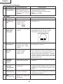
XG-MB70X
Maintenance indicator
Abnormal
Normal
Problem
Cause
• Blocked air intake
Temperature
warning
indicator
Off
• Relocate the projector to an area
with proper ventilation
The internal
• Take the projector to your nearest
Red on
temperature is
• Cooling fan breakSharp Authorized Projector Dealer
(Standby)
abnormally high.
down
or Service Center for repair.
• Internal circuit failure
• Clogged air intake
• Clean the exhaust and intake
vents.
The lamp does
not illuminate.
Lamp
indicator
Possible solution
Green on
Red on
Green blinks
when the lamp
is warming up
or shutting
down.
Red on
(Standby)
Time to change
the lamp.
The lamp does
not illuminate.
• The lamp is shut
down abnormally.
• Disconnect the power cord from
the AC outlet, and then connect it
again.
• Carefully replace the lamp.
• Remaining lamp life
becomes 5% or less. • Take the projector to your nearest
Sharp Authorized Projector Dealer
or Service Centerfor repair.
• Burnt-out lamp
• Lamp circuit failure • Please exercise care when
replacing the lamp.
Info
• If the temperature warning indicator illuminates and the projector enters the standby mode, check whether
any of the ventilation holes are blocked and then try turning the power back on. Wait until the projector has
cooled down completely before plugging in the power cord and turning the power back on.
(At least 10 minutes.)
• If the power is turned off for a brief moment due to power outage or some other cause while using the
projector, and the power supply recovers immediately after that, the lamp indicator will illuminate in red
and the lamp may not be lit. In this case, unplug the power cord from the AC outlet, replace the power
cord in the AC outlet and then turn the power on again.
• Do not unplug the power cord after the projector has entered the standby mode and while the cooling fan
is running. The cooling fan runs for about 90 seconds.
22
XG-MB70X
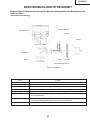
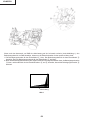
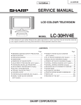
THE OPTICAL UNIT OUTLINE
Layout for proper setup of the optical components and parts (top view)
(Schematic diagram)
Reflection mirror
Projection lens
Color wheel
Lamp
Field lens
DMD
Rod
UV Filter
Illumination lenses 1
Illumination lenses 2
Item
Lamp
Color wheel
Rod
Illumination lenses
Reflection mirror
Field lens
DMD
Projection lens
Function
Light source. DC high-pressure mercury lamp.
Splits light from the light source into R, G, B and W through a color filter.
Assures uniform light ray.
Focus light from the rod on DMD.
Reflects light from the illumination lenses toward DMD.
Focuses light from the reflection mirror on DMD and then the light from DMD to
the projection lens.
Turns the internal micromirror ON/OFF at the rate of color component of each dot
of the input source to reflect light.
Enlarges light from DMD and projects it on a screen.
23
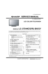
XG-MB70X
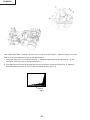
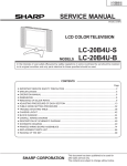
After replacing the DMD, if shading is present on the screen as shown in Figure 1, adjust the lighting area of the
DMD by turning the adjustment screws for the optical engine.
1. Loosen the fixing screw for the adjustment lever 1. Adjust the lighting area by adjustment lever 2 and
then tighten the fixing screw for the adjustment lever 1.
2. If the lightening area cannot be adjusted after the above procedure, loosen the fixing screw 3, adjust the
area with adjustment screws 4 and 5, and then tighten the fixing screw 3.
Shading
Fig. 1
24
XG-MB70X
ELECTRICAL ADJUSTMENT
No.
Adjusting point
Adjusting conditions
Adjusting procedure
1
EEPROM
initialization
1. Turn on the power (with the
lamp on) and warm up the
set for 15 minutes.
» Make the following settings.
Press S3563 to call the process mode and execute
"SS2" on SS menu.
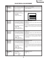
2
Adjustment of
CW index
1. Feed 64 STEP color bar
(XGA 60 Hz) to input 1.
2. Select the following group
and subject.
Group: DLP
Subject: Index Delay
1. Adjust the lamp patterns of RGB so that smooth
patterns appear without color blend and noise.
R
G
B
3
R Contrast
adjustment
(manual or
automatic)
1. Send white/black window
pattern signals with 91%
(0.64 Vpp)/0% of amplitude
level of XGA 60Hz to input
1.
2. Select the following group
and subjects.
Group : AD
Subject : R-Contrast
(Process GAMMA interlock)
1. Check the fixed value.
R-Bright: 63
2. Observe the chroma of 91% white window pattern
with CA100.
3. Increase the R-Contrast value on the screen with bit
dropouts. Adjust the value to +5 when bright red bit
dropouts occur on the black and the x value exceeds
30/100.
4
G Contrast
adjustment
(manual or
automatic)
1. Send white/black window
pattern signals with 91%
(0.64 Vpp)/0% of amplitude
level of XGA 60Hz to input
1.
2. Select the following group
and subjects.
Group : AD
Subject : G-Contrast
(Process GAMMA interlock)
1. Check the fixed value.
G-Bright : 63
2. Observe the chroma of 91% white window pattern
with CA100.
3. Increase the G-Contrast value on the screen with bit
dropouts. Adjust the value to +5 when bright green
bit dropouts occur on the black and the x value exceeds 30/100.
5
B Contrast
adjustment
(manual or
automatic)
1. Send white/black window
pattern signals with 91%
(0.64 Vpp)/0% of amplitude
level of XGA 60Hz to input
1.
2. Select the following group
and subjects.
Group : AD
Subject : B-Contrast
(Process GAMMA interlock)
1. Check the fixed value.
B-Bright: 63
2. Observe the chroma of 91% white window pattern
with CA100.
3. Increase the B-Contrast value on the screen with bit
dropouts. Adjust the value to +5 when bright blue bit
dropouts occur on the black and the x value exceeds
30/100.
6
DTV Bright/
Contrast adjustment
1. Select the following group
and subjects.
Group : DTV
Subject : Contrast
Bright
1. Check the fixed value.
Contrast : 4
Bright
: 40
25
XG-MB70X
No.
Adjusting point
Adjusting conditions
Adjusting procedure
7
DTV R Contrast
adjustment
(manual or
automatic)
1. Send white/black window
pattern signals with 100%
(0.7 Vpp)/0% of amplitude
level of 480P to input 1.
2. Select the following group
and subjects.
Group : AD2
Subject : R-Contrast2
(Process GAMMA interlock)
1. Check the fixed value.
R-Bright: 63
2. Observe the chroma of 100% white window pattern
with CA100.
3. Increase the R-Contrast2 value on the screen with
bit dropouts. Adjust the value to +5 when bright red
bit dropouts occur on the black and the x value exceeds 30/100.
8
DTV G Contrast
adjustment
(manual or
automatic)
1. Send white/black window
pattern signals with 100%
(0.7 Vpp)/0% of amplitude
level of 480P to input 1.
2. Select the following group
and subjects.
Group : AD2
Subject : G-Contrast2
(Process GAMMA interlock)
1. Check the fixed value.
G-Bright : 63
2. Observe the chroma of 100% white window pattern
with CA100.
3. Increase the G-Contrast2 value on the screen with
bit dropouts. Adjust the value to +5 when bright green
bit dropouts occur on the black and the x value exceeds 30/100.
9
DTV B Contrast
adjustment
(manual or
automatic)
1. Send white/black window
pattern signals with 100%
(0.7 Vpp)/0% of amplitude
level of 480P to input 1.
2. Select the following group
and subjects.
Group : AD2
Subject : B-Contrast2
(Process GAMMA interlock)
1. Check the fixed value.
B-Bright: 63
2. Observe the chroma of 100% white window pattern
with CA100.
3. Increase the B-Contrast2 value on the screen with
bit dropouts. Adjust the value to +5 when bright blue
bit dropouts occur on the black and the x value exceeds 30/100.
10
Adjustment of
DTV Tint
1. Select the following group 1. Check the fixed value.
and subject.
Tint
:5
Group : DTV
Subject : Tint
11
Adjustment of
DTV color saturation
1. Select the following group 1. Check the fixed value.
and subject.
Color
: 12
Group : DTV
Subject : Color
12
Adjustment of
DVD Bright /
Contrast
1. Select the following group 1. Check the fixed value.
and subject.
Contrast : 4
Group : DVD
Bright
: 40
Subject : Contrast
Bright
13
Adjustment of
DVD Tint
1. Select the following group 1. Check the fixed value.
and subject.
Tint
:5
Group : DVD
Subject : Tint
26
XG-MB70X
No.
Adjusting point
Adjusting conditions
Adjusting procedure
14
Adjustment of
1. Select the following group 1. Check the fixed value.
DVD color saturaand subject.
Color
: 12
tion
Group : DVD
Subject : Color
15
Video Bright /
Contrast adjustment
1. Select the following group
and subjects.
Group : VIDEO
Subject : Contrast
Bright
16
Adjustment of
VIDEO Tint
1. Select the following group 1. Check the fixed value.
and subject.
N-Tint
:5
Group : VIDEO
P-Tint
:5
Subject : N-Tint
S-Tint
:5
P-Tint
S-Tint
17
Adjustment of
VIDEO color
saturation
1. Select the following group 1. Check the fixed value.
and subject.
N-Color
:6
P-Color
:6
Group : VIDEO
S-Color
:6
Subject : N-Color
P-Color
S-Color
18
RGB white
balance adjustment
1. Send gray pattern signals
with 50% of amplitude level
of XGA60Hz.
2. Select the following group
and subjects.
Group : DLP
Subject : R-Contrast
B-Contrast
1. Adjust R-Contrast and B-Contrast so that the
following values for the chroma are obtained on
CL200 base:
x value: 290 ± 5
y value: 310 ± 5
19
sRGB white
balance adjustment
1. Send gray pattern signals
with 50% of amplitude level
of XGA60Hz.
2. Select the following group
and subjects.
Group : DLP
Subject : S-G-Contrast
S-B-Contrast
1. Adjust S-G-Contrast and S-B-Contrast so that the
following values for the chroma are obtained on
CL200 (6500K) base:
x value: 313 ± 5
y value: 329 ± 5
20
Auto keystone
initialization
1. Select the following group
and subjects.
Group : LINE
Subject : Calibration
1. Place the unit on the level surface, and adjust to 1
from 0.
2. Check that the K-Sensor value is 0 ± 3 and that
the keystone is caused by inclining the unit.
27
1. Check the fixed value.
Contrast : 4
Bright
: 40
XG-MB70X
Adjustment when assembling
No.
Adjusting point
21
Adjustment of
DLP voltage
Adjusting conditions
Adjusting procedure
1. Read voltage rank of DLP
description.
2. Set the switch corresponding to the rank which has
been read.
1. Carry out adjustment when DLP chip has been replaced or combination of chip and formatter has been
changed.
Rank:
B C D E
Setting value: 1 2 3 4
Checkpoints
No.
Adjusting point
Adjusting conditions
Adjusting procedure
22
Adjustment of
DLP Brightness
1. Select the following group
and subject.
Group : DLP
Subject : R-Bright
G-Bright
B-Bright
1. Check the fixed value.
Fixed value
: 32
23
RGB tone
reproduction
adjustment
1. Feed the SMPTE pattern
signal.
1. Make sure the 100% and 95% white as well as the
0% and 5% black gradations are visible.
24
White balance
checking and
readjustment
1. RGB Inputt, sRGB Input,
DTV Input, DVD Input,
VIDEO Input
Check that there is no deviation of white balance with
the monitor.
25
Off-timer performance
1. Select the following group 1. Select OFF from the process mode.
and subjects.
Make sure the off-timer starts with 5 minutes
Group : LAMP
onscreen and count one minute in one second.
Subject : OFF
And then indication is 0 minute, the power supply
of the set is cut off.
26
Thermistor
performance
checking
1. Heat the thermistor with a
hair dryer.
1. Make sure that the temperature is indicated.
27
Auto sync
performance
checking
1. Feed the phase check pattern signal.
1. In the VGA, SVGA, XGA and SXGA modes, make
sure the Clock, Phase, H-Pos and V-Pos settings
can be automatically adjusted.
28
USB operation
check
1. Connect to a PC with a
USB cable.
1. Check that advance/reverse operation on PC screen
is possible by using remote control.
29
LAN operation
check
1. Connect to a PC with a
LAN cable.
1. Check that communication is possible.
28
XG-MB70X
No.
Adjusting point
30
Delivery settings
Adjusting conditions
Adjusting procedure
1. Make the following settings.
Destination
Process
USA
China
Europe and
the Other
Contries
29
Remote control
adjustment
SS4
SS6
adjustment
Factory setting at 4
Factory setting at 6
SS3
Factory setting at 3
XG-MB70X
AF (autofocus) inspection
< Camera >
Required conditions:
1. Place the unit in front of the screen (size: 60-inch diagonal) at the distance of 1.8m. There is no light source such as
a fluorescent light or reflector in the background.
2. Focus is adjusted correctly.
3. RGB input of 256-gradation pattern.
Method:
1. Send AF inspection command ("_CMR 1").
2. Check that the response command is "OK".
< AF function >
Required conditions:
1. Place the unit in front of the screen (size: 60-inch diagonal) at the distance of 1.8m. There is no light source such as
a fluorescent light or reflector in the background.
Method:
1. Press the AF button. AF operation must end within 11 seconds.
2. Check that the difference from the just focus point is within ±15cm.
* The above time applies when the focus start position is not fixed.
After the camera inspection, AF operation must end within 6 seconds.
Calling and quitting the process mode with the control keys on this model.
∗ Although it is possible for the process OUT to exit using the process menu, the IN/OUT toggle command is also
available considering the existing specification.
1. Calling and quitting
With the menu not displayed, press the "ENTER", "ENTER", "VOL+", "VOL-", "ENTER", "ENTER" and "MENU"
keys on main unit.
2. Others
Press the S3563 process key (toggle) on the main PWB to call and quit the process menu.
Note: When adjusting in the process mode, set a signal with a vertical frequency of 60 Hz or no signal. (May not be
properly adjusted with other signals.)
Resetting the lamp timer for this model
1. Resetting procedure
In Stand-by, run this command to clear the operating time of the lamp to 0 and turn on the power.
Press and hold "DOWN", "ENTER", and "MENU", and then press the "ON" key of the set.
Forced disabling of the System-Lock of this model
1. Disabling procedure
With System-Lock input window onscreen, press the "MENU", "ENTER", "ENTER", "MENU", "ENTER", "ENTER"
and "MENU" keys, in this order, on the remote controller.
30
XG-MB70X
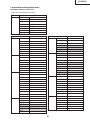
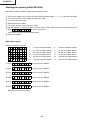
» Adjustment mode process menu
Adjustment mode process menu 1
* Adjust only the shaded items below.
First layer
Adjustment Process Menu
DTV
VERSION
DVD
SS
VIDEO
TEMP
AD
OPTION
AD2
LAMP
DLP
LINE
VIDEO1
Pedestal
EXIT
second layer
Contrast
Tint
Color
Sharpness
Bright
B-DRIVE
R-DRIVE
EXIT
DVD
Contrast
Tint
Color
Sharpness
Bright
B-DRIVE
R-DRIVE
EXIT
VIDEO
Contrast
N-Tint
P-Tint
S-Tint
N-Color
P-Color
S-Color
Sharpness
Bright
B-DRIVE
R-DRIVE
EXIT
AD
R-Bright
G-Bright
B-Bright
R-Contrast
G-Contrast
B-Contrast
EXIT
DTV
second layer
R-Bright2
G-Bright2
B-Bright2
R-Contrast2
G-Contrast2
B-Contrast2
EXIT
DLP
Index Delay
R-Bright
G-Bright
B-Bright
R-Contrast
G-Contrast
B-Contrast
SR-Cont
SG-Cont
SB-Cont
EXIT
VIDEO1
N-Contrast
P-Contrast
S-Contrast
Color
NT3.58Delay
NT4.43Delay
PAL Delay
SECAM Delay
EXIT
Pedestal R-Bright
G-Bright
B-Bright
R-Contrast
G-Contrast
B-Contrast
EXIT
Initial Value
AD2
4
5
12
2
40
41
41
4
5
12
3
40
41
41
4
5
5
5
6
6
6
3
40
41
41
63
63
63
155
155
155
31
Initial Value
63
63
63
155
155
155
10500
32
32
32
34
34
34
34
34
34
12
13
14
17
1
1
1
3
-10
-10
-10
15
15
15
XG-MB70X
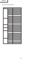
Adjustment mode process menu 2
second layer
VERSION Build
Boot Code
Config
RomCode
GUI
DLP
AF Unit
LAN
EXIT
SS
SS2
SS3 EU
SS4 US
SS5 JPN
SS6 CHIN
EXIT
TEMP
Temp1
Temp2
EXIT
OPTION Pixel Gamma
DLP Gamma
EXIT
LAMP
Current Time
History1
History2
History3
History4
TOTAL TIME
EXIT
LINE
OFF
LED CHECK
Calibration
K-Senser
EXIT
Initial Value
Parameter of sensor1
Parameter of sensor2
Standard RGB
4
Current time of use
One Earlier
Two Earlier
Three Earlier
Four Earlier
Total operating hours
32
XG-MB70X
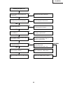
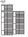
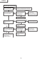
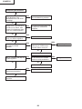
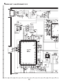
TROUBLESHOOTING TABLE
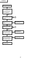
Checking the basic operation
Does the power LED light up or flash in
red or green?
NO
Go to "Checking the power supply system".
YES
Does the set function with its keys or the
remote controller?
NO
Go to "Checking the peripheral circuits of
the microprocessor".
YES
Does the cooling fan rotate, and the lamp
turn on?
NO
Go to "Checking the lamp light-up".
YES
Is the user menu displayed?
NO
Go to "Checking the peripheral circuits of
the formatter".
NO
Go to "Checking the RGB input".
YES
Does the analog RGB input function
normally?
YES
Does the component input function
normally?
NO
Go to "Checking the component".
YES
Does the VIDEO input function normally?
NO
Go to "Checking of VIDEO input ".
YES
Does the LAN function?
NO
Go to "Checking the LAN".
YES
Does the RS-232C function?
NO
Go to "Checking RS-232C".
YES
Does the autofocus function?
NO
Go to "Checking the autofocus".
YES
End.
33
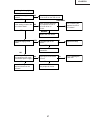
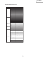
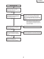
XG-MB70X
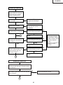
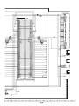
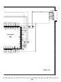
Checking the power supply system
Is 13V output to pins (9) and (11) of
P1707?
NO
Go to "Checking the power unit".
YES
Is 6V output to pins (1) and (3) of P1707? NO
Go to "Checking the power unit".
YES
Is the connector of P1708 fully inserted? NO
Is the voltage of 6V applied to both ends?
Replace the thermal fuse.
YES
NO
Check IC1776 and peripheral circuits.
Is B+5VAT output from IC1776?
YES
Is BU+3.3V output from IC1708?
NO
Check IC1708 and peripheral circuits.
YES
NO
Check IC1733 and peripheral circuits.
Is BU+2.5V output from IC1733?
YES
Go to "Checking the peripheral circuits of
the microprocessor".
34
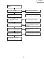
XG-MB70X
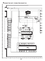
Checking the power unit
Is each connector of the power unit
fully inserted?
NO
Securely insert the connectors.
YES
Is the lamp door closed completely?
NO
Fix the lamp door with screws.
YES
Is the bimetal broken?
NO
Replace the bimetal switch or restore
by pressing the red button.
NO
Replace F701. If other parts are
damaged, replace them.
YES
Is AC voltage applied to both AC input
ends of DB701?
YES
Is DC voltage of approx. 6.25V output
to both ends of C726?
NO
Check D707 and the peripheral circuits
of IC702 on the primary side. If
defective, replace them.
YES
Is DC voltage of approx. 370V output to NO
the cathode of D701?
YES
Is the specified voltage output to each
output terminal of EA701?
NO
Replace the subunit or check the
primary side circuit.
Replace defective parts if any.
Check the secondary-side circuits of
T701. If defective, replace them.
YES
Check the PWB circuits on each output
side.
Replace the ballast power supply.
35
ABNORMAL
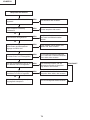
XG-MB70X
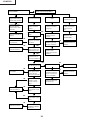
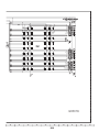
Checking the peripheral circuits of the
microprocessor
Are the voltages of approx. 3.3V and 2.5V
applied to both ends of C2030 and C2029
respectively?
NO
Go to "Checking the power supply
system".
YES
Are the oscillations of 133MHz and
64MHz output from pin (3) of X2001 and
pin (3) of X2002 respectively?
NO
Check the peripheral circuits of X2001
and X2002.
YES
Does each terminal of R2039, R2040,
R2042, R2048 and R2050 change?
NO
Check IC2201 and IC2202. IC2003 is
defective.
NO
Check IC2203. IC2201 is defective. The
I2C bus does not function normally.
NO
IC2201 is defective. The keys do not
function normally.
YES
Do pins (95) and (96) of IC2201 change?
YES
Do pins (74) to (77) and (89) to (94) of
IC2201 change when any key is
operated?
YES
When the power button is pressed, does
the voltage of pin (7) of IC2005 become
3.3V?
NO
IC2003 is defective.
YES
Do pulse-shaped waveforms appear at
pins (1), (2), (5) and (6) of IC2005?
NO
IC2005 is defective.
YES
Does the voltage of pins (2) and (6) of
IC2006 and pins (3) and (6) of IC2007
change?
NO
IC2006 or IC2007 is defective.
YES
Is the voltage of pin (9) of IC3560 5V?
NO
IC3560 is defective.
YES
Does the fan rotate?
Check the power supply circuit or fan
circuit on the main circuit.
NO
YES
Go to "Checking the lamp light-up".
36
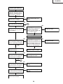
XG-MB70X
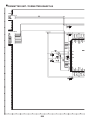
Checking the lamp light-up
Does each cooling fan
function?
NO
Check the power supply circuit
or fan circuit on the main circuit.
YES
Is the rotating sound of the
color wheel heard?
ABNORMAL
NO
YES
Check IC9102, 9003 and
the peripheral circuits of
the motor driver IC
IC9101.
Go to "Checking the
peripheral circuits of
the formatter".
NORMAL
Replace the color wheel.
Is the discharging sound
heard?
YES
Is the lamp tight in the
socket?
NO
Replace the lamp.
YES
Securely insert the
connectors.
NO
Is DC voltage of approx.
NO
370V applied to both ends
of the ballast power supply?
YES
Go to "Checking the
peripheral circuits of the
formatter".
Is pin (2) of P1707 at the
H level?
NO
Check IC1701, IC2003 and
their peripheral circuits.
37
YES
Go to "Checking the
power unit".
XG-MB70X
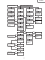
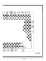
Checking the peripheral circuits
of the formatter
What is the screen problem?
The rainbow-like screen is
displayed. Each color (R,
G and B) does not match.
The screen is all black.
The problem remains
even after adjusting
"Process menu", "DLP"
and "Index".
Is the socket of
SC9001 connected
properly?
Thick and white
vertical lines (flash).
Other
Are contact terminals
of DMD, the formatter
board and CLGA
dirty?
Is the socket of
SC9001 connected
properly?
YES
YES
Does the color wheel
rotate?
IC9003 and IC9004 are
defective.
YES
Is the voltage of pin (3)
of IC9001 normal
(+2.5V)?
NO
NO
Check the main PWB
and power unit.
NO
Reinstall DMD, optical
mechanism, and
Formatter PWB.
YES
Is the proper voltage
supplied to the socket
of SC9001?
Is there a sine wave of
400MHz at pins (18)
and (20) of IC9001?
YES
NO
IC9001 or its
peripheral circuits are
defective.
YES
Is the voltage of the
positive polarity pin of
C9308 normal (+5V)?
IC9301 or its peripheral
circuits are defective.
YES
IC9003, IC9004,
IC9006 or their
peripheral circuits are
defective.
YES
IC9101, 9102, their
peripheral circuits or
color wheel is defective.
NO
NO
Does the fan rotate?
Does the lamp turn on?
NO
YES
YES
NO
When no signal is sent, is
a pulse signal of 180Hz
present on pin (2) of
P1705 on the main PWB?
Check the color wheel
sensor PWB.
Is the pulse-shaped
waveform supplied to
the pin (14) of P1707
on the main PWB?
YES
NO
NO
YES
Is the voltage of pin (9)
of IC9301 normal
(between +23 and
+26V)?
Check the ballast unit
and power unit.
YES
Is the voltage of pin
(13) of IC9301 normal
(-26V)?
IC9301 or its peripheral
circuits are defective.
YES
NO
Is the voltage of pin
(49) of IC9301 normal
(+7V)?
NO
IC9301 or its
peripheral circuits are
Check the fan circuits.
Is there a pulse signal
of 60MHz at TP9055
(DCLK_L)?
38
IC2003, 1701 or their
peripheral circuits are
defective.
XG-MB70X
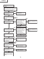
Checking the RGB input
Send RGB signals to INPUT1
or INPUT2. Use keys on the
main unit or remote control to
select INPUT1 or INPUT2.
NO
Are sync signals input to pins
(30) and (31) of IC3005?
YES
Are picture signals input to pins
(43), (48) and (54) of IC3005?
Go to "Checking the sync
signal".
YES
1
NO
NO
NO
Are picture signals input to
pins (2), (5), (11), (3), (6) and
(10) of IC3003?
YES
When toggling between INPUT1
and INPUT2 by using keys on
the main unit and remote
control, does the voltage of pin
(1) of IC3003 change?
Check Q3123, IC2003 and
peripheral circuits.
YES
Replace IC3003.
NO
Are picture signals input to pins
(1), (5) and (8) of IC4003, and
pins (1), (5) and (8) of IC4004?
YES
Check SC4003, SC4001 and
peripheral circuits.
YES
When toggling between INPUT1 NO
and INPUT2 by using keys on
the main unit and remote control,
does the voltage of pins (2), (4)
and (7) of IC4003, and pins (2),
(4) and (7) of IC4004 change?
YES
Replace IC4003 or IC4004.
NO
Check IC3106, 3107, 3108
and peripheral circuits.
Are picture signals input to pins (43),
(48) and (54), and sync signals input
to pins (30) and (31) of IC3005?
YES
1
NO
Are sync signals output from pins
(64), (65) and (66), and sine wave
output from pin (67) of IC3005?
YES
Are signals input to pins (56),
(58), (62) and (64) of SC2501?
Check IC3005 and peripheral
circuits.
NO
Check IC8001 and peripheral
circuits.
YES
Go to "Checking the peripheral
circuits of the formatter".
39
Check IC4009, IC2003 and
peripheral circuits.
XG-MB70X
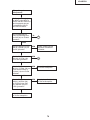
Checking the Component
Send component signals to
INPUT1 or INPUT2. Use
keys on the main unit or
remote control to select
INPUT1 or INPUT2.
YES
Is picture signal including
sync signal input to pin (46)
of IC3002?
YES
2
NO
Are picture signals input to
pins (8), (9) and (10) of
IC3101?
NO
Check IC4003, IC4004 and
peripheral circuits.
YES
Are picture signals output
from pins (35), (37) and
(39) of IC3101?
NO
1
YES
Are picture signals sent
from pins (76), (77) and
(78) of IC3101 to pins (17),
(18) and (19) of IC3103?
NO
Check IC3101 and
peripheral circuits.
NO
Check IC3103 and
peripheral circuits.
YES
Are picture signals sent
from pins (21), (22) and
(23) of IC3103 to pins (67),
(68) and (69) of IC3101?
YES
Check IC3101 and
peripheral circuits.
40
XG-MB70X
Checking of Video input
Send composite VIDEO
signals to INPUT3. Use keys
on the main unit or remote
control to select INPUT3.
Is picture signal input to pin
(1) of IC3103?
NO
Check the VIDEO-IN signal line
of Q3104 and soldering of
J3101.
YES
Check the peripheral circuits of
C3103 and color system
malfunctions.
YES
Is input signal SECAM?
NO
NO
Are picture signals input to
pins (39) and (41) of IC3103?
YES
Check IC3105 and peripheral
circuits.
YES
2
Are picture signals output
from pins (21), (22) and (23)
of IC3103?
Do pulse-shaped waveforms appear NO
at pins (15) and (16) of IC3105?
NO
Do pulse-shaped waveforms appear NO
at pins (13) and (14) of IC3103?
YES
YES
Check IC3103 and peripheral
circuits.
Are picture signals input to
pins (67), (68) and (68), and
output from pins (35), (37)
and (38) of IC3101?
NO
The I2C bus line does
not function normally.
Check IC2201, IC2003,
IC2005, IC2006, IC2007
and their peripheral
circuits.
Check if IC connected to
I2CBUS functions
normally.
Do pulse-shaped waveforms appear NO
at pins (55) and (56) of IC3101?
YES
Check IC3101 and peripheral
circuits.
YES
1
Checking of S-Video input
Send S terminal (Y and C) signals to INPUT4.
Use keys on the main unit or remote control to
select INPUT4.
Are picture signals output from pins (43) and
(44) of IC3103?
NO
Check the soldering of J3101.
YES
2
41
XG-MB70X
Checking of Sync signal
Are HV sync signals sent to
pins (1) and (6) of IC4010?
YES
NO
Check IC4008 and peripheral
circuits.
NO
IC4008 and IC4010 are
defective.
Are HV sync signals sent to
pins (22) and (23) of IC3002?
YES
Are sync signals sent to pins
(28) and (29) of IC3002?
NO
Is a clock of 27MHz sent to pin
(42) of IC3002?
Do signals of pins (21) and (22)
of IC3002 change?
YES
Check IC3002 and peripheral
circuits.
NO
IC3005 and peripheral circuits
are defective.
Are sync signals sent to pins
(65) and (64) of IC3005?
YES
Is the timing of vertical and
horizontal sync signals
correct?
Sync signal is normal.
NO
Is the signal generator (input
source) correct?
Check X3001 and
peripheral circuits.
YES
YES
YES
NO
YES
IC2003 and peripheral circuits
are defective.
NO
Set the signal source correctly.
42
NO
The I2C bus line does not
function normally.
Check IC2201, IC2003,
IC2005, IC2006, IC2007
and their peripheral
circuits.
Check if IC connected to
I2CBUS functions
normally.
XG-MB70X
Checking the autofocus
Is dust, dirt or damage present
on the auto focus sensor
cover?
NO
Remove the dust and dirt, or
replace.
YES
Are voltages of 3.3V, 1.5V and
2.8V applied to pin (4) of X5001,
pin (94) of IC5003 and pin (5) of
IC5008 respectively?
NO
Check the power supply circuit
and its peripheral circuits.
YES
NO
X5001 is defective.
Is a clock (49MHz) output from
pin (3) of X5001?
YES
Is a clock (12.27MHz) output
from pin (108) of X5003?
NO
YES
NO
Does the signal of pin (6) of
IC5004 change right after 3.3V
is applied?
Check IC5003.
YES
Check IC5004.
Is a clock sent to pin (93) of
IC5003?
NO
YES
Is the camera FPC properly
connected to the connector?
YES
The camera is defective.
When auto focus is performed,
does pin (121) of IC5003
change?
NO
Check IC5005 and IC5006.
YES
Check the motor drive circuit.
43
NO
Connect properly.
XG-MB70X
Checking the LAN
LAN communication is disabled even
though connecting the control PC with a
LAN cable. The LINK LED (green) does
not light up.
YES
Are the connection of connecting cable
and the settings of IP address, sub-net
address and default gateway correct?
NO
YES
Check the connecting cable and LAN settings. If the
LAN settings are unknown, contact the network
administrator.
If the network settings cannot be saved, replace
IC8003 (EEP ROM) as it may be defective.
Note: When IC8003 (EEP ROM) is replaced, the MAC
address returns to default. Refer to "Resetting
after replacing IC8003 (EEP ROM)" to reset.
NO
Are the network device (e.g. Hub)
between the control PC and XG-MB70X
and cable normal?
Repair defective parts in the network.
YES
When data is sent from the control PC, do
pins (30) and (31) of IC8201 (PHY
receiver) receive signals?
NO
Check the peripheral circuit of J8201 (RJ-45 jack
with built-in transformer).
YES
Check the PHY receiver IC8201 and the
peripheral circuits of the microprocessor
IC8001.
44
XG-MB70X
Checking RS-232C
Communication is disabled even though
connecting the control PC and projector
with a RS-232C cable.
YES
Is the connecting cable connected
correctly? (cross cable)
NO
Replace the connecting cable.
YES
NO
Does pin (8) of IC8002 receive a signal?
Check R8002 and the peripheral circuits of SC8001.
YES
NO
Check the peripheral circuits of IC8002.
Does pin (4) of IC8202 receive a signal?
YES
Do pin (3) of IC8202 output a signal?
NO
Check IC8202 and the peripheral circuits of the
microprocessor IC8001.
YES
NO
Does pin (106) of IC2201 receive a
signal?
Check the peripheral circuits of the microprocessor
IC8001 and IC2201.
YES
NO
Do pin (105) of IC2201 output a signal?
Check the peripheral circuits of the microprocessor
IC2003 and IC2201.
YES
Check the peripheral circuits of the
microprocessor IC8001.
45
XG-MB70X
Resetting after replacing IC8003 (EEP ROM)
MAC address returns to default. Follow the steps below to reset.
1 Open the top cabinet of the projector and confirm the MAC address (MAC: ************) of the seal on the PWB.
2 Connect the control PC and projector with a RS-232C cable.
3 Turn on the AC power supply.
4 EEP ROM returns to default.
5 Turn off the AC power supply and turn on again.
6 Set MAC address by using the RS-232C command. (Refer to "MAC address setting" for the setting procedure.)
7 Enter
and check the response.
Check that it is the same as the set MAC address.
8 Setting is completed.
MAC address setting
RS-232C commands to be used
*1
1st byte of the MAC address
*2
2nd byte of the MAC address
*3
3rd byte of the MAC address
*4
4th byte of the MAC address
*5
5th byte of the MAC address
*6
6th byte of the MAC address
*7
7th byte of the MAC address
*8
8th byte of the MAC address
*9
9th byte of the MAC address
*10
10th byte of the MAC address
*11
11th byte of the MAC address
*12
12th byte of the MAC address
1 Enter
and [*2], and press "ENTER".
Responds "OK".
2 Enter
and [*2], and press "ENTER".
Responds "OK".
3 Enter
and [*2], and press "ENTER".
Responds "OK".
4 Enter
and [*2], and press "ENTER".
Responds "OK".
5 Enter
and [*2], and press "ENTER".
Responds "OK".
6 Enter
and [*2], and press "ENTER".
MAC address setting is completed.
46
XG-MB70X
SPEZIFIKATIONEN
Produkttyp
Modell
Videosystem
Anzeigeverfahren
DMD-Panel
Objektiv
Projektionslampe
Eingangs(INPUT 1/2)-/
Ausgangs(OUTPUT)-signal-Komponente
Horizontale Auflösung
Computer-RGB-Eingangs (INPUT 1/2)-/
Ausgangs(OUTPUT)-signal
Video-Eingangssignal
(INPUT 3)
S-Video-Eingangssignal
(INPUT 4)
Audio-Eingangssignal
USB-Anschluss
RS-232C-Anschluss
LAN-Anschluss
Pixeltakt
Vertikale Frequenz
Horizontale Frequenz
Audio-Ausgang
Lautsprechersystem
Nennspannung
Eingangsstrom
Nennfrequenz
Leistungsaufnahme
Multimedia-Projektor
XG-MB70X
NTSC3.58/NTSC4.43/PAL/PAL-M/PAL-N/PAL-60/SECAM/
DTV480I/DTV480P/DTV540P/DTV576I/DTV576P/DTV720P/DTV1035I/DTV1080I
Single Chip Digital Micromirror DeviceTM (DMDTM) von Texas Instruments
Panel-Größe: 0,7"
Anzahl der Bildpunkte: 786.432 Bildpunkte (1.024 [H] ✕ 768 [V])
1,5 ✕ Elektronik-Zoom/Fokuslinse, F2,0 – 2,5, f = 21,3 – 31,6 mm
Gleichstromlampe 275 W
15-pol.-Mini-D-Sub-Anschluss
Y: 1,0 Vp-p, negatives Sync., 75 Ω terminiert
PB: 0,7 Vp-p, 75 Ω terminiert
PR: 0,7 Vp-p, 75 Ω terminiert
750 Fernsehzeilen (DTV 720P)
15-pol.-Mini-D-Sub-Anschluss
RGB getrennt/Sync. auf Grüπn-Typ analoger Eingang: 0-0,7 Vp-p, positiv, 75 Ω terminiert
HORIZONTALES SYNC.-SIGNAL: TTL-Pegel (positiv/negativ)
VERTIKALES SYNC.-SIGNAL: Wie oben
RCA-Anschluss: VIDEO, Verbund-Video, 1,0 Vp-p, negatives Sync., 75 Ω terminiert
4-pin-Mini-DIN-Anschluss
Y (Luminanzsignal): 1,0 Vp-p, negatives Sync., 75 Ω terminiert
C (Chrominanzsignal): Stoß 0,286 Vp-p, 75 Ω terminiert
ø3,5 mm-Ministecker: AUDIO, 0,5 Vrms, mehr als 22 kΩ (Stereo)
4-pol. USB-Mini B-Typ-Buchse
9-pol. Mini-DIN-Anschlus
8-pol. RJ-45-Modularanschluss
12-108 MHz
43-85 Hz
15-70 kHz
2,0 W (Mono)
4,0 cm ✕ 2,85 cm oval ✕ 1 16Ω
100-240 V Wechselstromspannung
3,9 A
50/60 Hz
370 W (Standard-Modus)/320 W (Eco-Modus) bei AC 100 V
350 W (Standard-Modus)/300 W (Eco-Modus) bei AC 240 V
6 W (bei AC 100 V)-8 W (bei AC 240 V)
Leistungsaufnahme
(Bereitschaft)
Wärmeableitung 1.390 BTU/Stunde (Standard-Modus)/1.200 BTU/stunde (Eco-Modues) bei AC 100 V
1.315 BTU/Stunde (Standard-Modus)/1.130 BTU/stunde (Eco-Modues) bei AC 240 V
Betriebstemperatur 41°F bis 104°F (+5°C bis +40°C)
Lagertemperatur –4°F bis 140°F (–20°C bis +60°C)
Gehäuse Kunststoff
I/R-Trägerfrequenz 38 kHz
Abmessungen (ca.) 12 7/32" ✕ 3 33/64" ✕ 11 7/64" (310 (B) ✕ 89 (H) ✕ 282 (T) mm) (nur Hauptgerät)
12 7/32" ✕ 4 7/64" ✕ 11 5/16" (310 (B) ✕ 104 (H) ✕ 287 (T) mm) (einschließlich Einstellfüße und Projektionsteile)
Gewicht (ca.) 9,1 lbs. (4,1 kg)
Replacement parts Lampeneinheit (Lampen-/Gehäusemodul) (AN-MB70LP), Fernbedienung (RRMCGA313WJSA), Netzkabel für
USA, Kanada usw. (QACCDA010WJPZ), Netzkabel für Europa, außer Großbritannien (QACCVA011WJPZ),
Netzkabel für Großbritannien, Hongkong und Singapur (QACCBA036WJPZ), Netzkabel für Australien,
Neuseeland und Ozeanien (QACCLA018WJPZ), RGB-Kabel (QCNWGA045WJPZ), USB-Kabel
(QCNWGA014WJPZ), Tragetasche (GCASNA014WJSA), Objektivkappe (RCAPHA021WJSA),
Projektorhandbuch- und Technische Referenz-CD-ROM (UDSKAA052WJZZ), "QUICK GUIDE
(Schnellanleitung)"-Aufkleber (TLABZA717WJZZ), Bedienungsanleitung (TiNS-B416WJZZ)
Bedingt durch fortlaufende technische Verbesserungen behält sich SHARP das Recht vor, das
Design und die Spezifikationen ohne vorherige Ankündigung ändern zu können. Die angegebenen
Leistungswerte stellen die Nennwerte einer in Serienherstellung produzierten Einheit dar. Geringe
Abweichungen bei einzelnen Geräten sind möglich.
47
XG-MB70X
HINWEISE FÜR DAS
WARTUNGSPERSONAL
123456789012345678901234567890121234567890123456
123456789012345678901234567890121234567890123456
123456789012345678901234567890121234567890123456
ACHTUNG: UV-STRAHLUNG
123456789012345678901234567890121234567890123456
123456789012345678901234567890121234567890123456
123456789012345678901234567890121234567890123456
Die Beleuchtungsquelle des LCD-Projektors, eine
UHP-Lampe, emittiert eine geringe Menge
UV-Strahlung.
DIREKTE BESTRAHLUNG AUF AUGEN
UND HAUT MUSS VERMIEDEN WERDEN.
Zur Gewährleistung der Sicherheit muß folgendes
beachtet werden:
Auswechseln der Lampe
Hinweis:
Da die Lampe während des Betriebs sehr heiß wird, sollte
die Lampe erst ausgewechselt werden, nachdem das
Gerät mindestens eine Stunde ausgeschaltet war, damit
die Lampe ausreichend abkühlen kann.
Beim Installieren der neuen Lampe muß darauf
geachtet werden, die Lampe selbst (Glaskolben)
nicht zu berühren. Vielmehr muß die Lampe am
Reflektor 2 gehalten werden.
[Es darf nur ein Original-Ersatzteil verwendet
werden.]
1 Lampe
1. Bei Arbeiten am Projektor bei eingeschalteter
Lampe und abgenommenem oberen Gehäuse muß
unbedingt eine Sonnenbrille getragen werden.
2 Reflektor
GEFAHR! — Niemals die Spannungsversorgung
einschalten, ohne daß eine Lampe vorhanden ist, um
elektrische Schläge und Schäden am Gerät zu
vermeiden, da der Stabilisator anfangs hohe
Spannungen erzeugt.
2. Die Lampe darf nicht außerhalb des
Lampengehäuses eingeschaltet werden.
Da eine geringe Menge UV-Strahlung an der Öffnung
zwischen den Lüftern austritt, wird empfohlen, während
der Wartungsarbeiten die Abdeckkappe des Zusatzobjektivs an dieser Öffnung anzubringen, um Augen
und Haut vor den UV-Strahlen zu schützen.
3. Betrieb für länger als 2 Stunden bei
abgenommenem Gehäuse ist nicht zulässig.
Zur Beachtung bei UV-Strahlung
und Mitteldruck-Lampen
1. Vor dem Auswechseln der Lampe muß der Netzstecker
gezogen werden.
2. Vor Durchführung von Wartungsarbeiten muß das
Gerät eine Stunde abkühlen.
3. Die Lampe darf nur gegen eine der gleichen Art
ausgewechselt werden. Typ AN-MB70LP, bemessen für
275W.
4. Die Lampe gibt eine geringe UV-Strahlung ab, daher
muß direkter Augenkontakt vermieden werden.
5. Die Mitteldruck-Lampe weist ein Explosionsrisiko auf.
Daher müssen die nachstehenden
Installationsanweisungen beachtet werden, und die
Lampe muß vorsichtig behandelt werden.
48
XG-MB70X
Vorsichtsmaßregeln für bleifreien Lötzinn
1 Verwendung von bleifreiem Lötzinn
Bei den Platinen für dieses Modells wird bleifreies Lot verwendet. Das Symbol LF kennzeichnet bleifreies Lot und
findet sich an den Platinen und in den Wartungshandbüchern. Der Buchstabe hinter LF bezieht sich auf die Art des
bleifreien Lots.
Beispiel:
LFa
Zeigt bleifreien Lötzinn aus Zinn, Silber und Kupfer an.
2 Bei Reparatur der mit bleifreiem Lötzinn gelöteten Platine immer bleifreien Lötzinn verwenden. Reparatur mit
herkömmlichem Lötzinn kann zu Schäden oder Unfällen aufgrund von Rissen führen.
Da der Schmelzpunkt bleifreien Lvtzinns (Sn-Ag-Cu) um 40°C höher als der von Bleidraht-Lötzinn ist, empfehlen
wir die Verwendung einer speziellen Lötspitze. Wenn Fragen über den Beschaffung leitfreien Lötzinns oder spezieller
Lötspitzen bestehen, wenden Sie sich an unsere Kundendienstvertretung in Ihrem Gebiet.
3 Löten
Da der Schmelzpunkt bleifreien Lötzinns (Sn-Ag-Cu) etwa 220°C beträgt, was um 40°C höher als der von bleihaltigem
Lötzinn ist, und außerdem schlechte Löt-Benetzbarkeit aufweist, kann es erforderlich werden, die Lötspitze längere
Zeit in Kontakt mit der Platine zu halten. Da die Lötlauge abfliessen kann oder der maximale Hitzewiderstand von
Teilen überschritten werden kann, die Lötspitze sofort von der Platine nehmen, sobald eine gute Lötung erzielt ist.
Bleifreier Lötzinn enth_lt mehr Zinn, und das Ende der Lötspitze kann leicht angegriffen werden. Immer sicherstellen,
dass der Lötkolben nur bei Bedarf eingeschaltet wird.
Wenn ein anderer Typ von Lötzinn an der Lötspitze haften bleibt, verschmilzt er mit dem bleifreien Lötzinn. Die
Lötspitze nach jeder Verwendung reinigen.
Wenn die Lötspitze bei der Verwendung geschwärzt wird, die Spitze mit Stahlwolle oder feinem Sandpapier
abschmirgeln.
Immer beim Austausch von Teilen vorsichtig sein, und die Polaritätsanzeige auf der Platinenbeschriftung beachten.
Bleifreier Lötzinn zur Wartung
Teile-Nr.
ZHNDAi123250E
ZHNDAi126500E
ZHNDAi12801KE
★
J
J
J
Beschreibung
φ0.3mm
250g(1roll)
φ0.6mm
500g(1roll)
φ1.0mm
1 Rolle
49
Code
BL
BK
BM
XG-MB70X
Bendienungsanleitung
50
XG-MB70X
51
XG-MB70X
52
XG-MB70X
53
XG-MB70X
54
XG-MB70X
Pin-Belegung
55
XG-MB70X
ABMESSUNGEN
56
XG-MB70X
ENTFERNEN DER HAUPTTEILE
1. Ausbau der Lampentür und der Lampeneinheit
1-1. Die Lampentür-Befestigungsschraube herausdrehen, dann die Lampentür abnehmen.
1-2. Die 2 Lampeneinheits-Befestigungsschrauben herausdrehen, dann die Lampeneinheit abheben.
Lampeneinheit
1-3
Lampentür
1-2
2. Ausbau des oberen Gehäuses
2-1. Die 6 Befestigungsschrauben für das obere und das untere Gehäuse herausdrehen.
2-2. Die Befestigungsschraube für das obere Gehäuse (Klemmenseite) herausdrehen.
2-3. Die mit * bezeichneten Teile gedrückt halten und die Klauen am oberen Gehäuse freigeben, um das obere
Gehäuse abzunehmen.
Oberes Gehäuse
2-2
Unteres Gehäuse
2-1
57
XG-MB70X
3. Ausbau der Hauptleiterplatteneinheit und der peripheren Einheiten
3-1.
3-2.
3-3.
3-4.
3-5.
3-6.
3-7.
3-8.
Die 2 Hauptleiterplatten-Befestigungsschrauben (Klemmenseite) herausdrehen.
Die 8 Hauptleiterplatten-Befestigungsschrauben herausdrehen.
Die 14 Anschlüsse aus der Hauptleiterplatte entfernen.
Den Anschluss an der Schalterhalterung herausziehen, dann die 3 Befestigungsschrauben herausdrehen.
Die Befestigungsschrauben für die vordere R/C-Leiterplatte herausdrehen.
Die 2 Befestigungsschrauben für die A/F-Haltereinheit herausdrehen.
Die Hauptleiterplatte in querer Richtung von der Optische Laufwerkeinheitseite abheben.
Die Lautsprecherhalter-Baugruppe abnehmen.
Hauptleiterplatteneinheit
3-3
Erdleitung
[RA]
[FC]
[FA]
[FB]
[TO]
3-2
3-4
[TF]
Schalterhalterungseinheit
[DD]
[SC5001]
[CW] [FD]
[AZ]
[AI] [SO]
3-5
[EA]
3-7
Vordere R/CLeiterplatte
3-1
3-8
3-6
LautsprecherhalterBaugruppe
A/F-Haltereinheit
4. Ausbau der optischen Laufwerkeinheit
4-1. Die Befestigungsschraube für die optische Laufwerkeinheit am unteren Gehäuse herausdrehen.
4-2. Die 5 Befestigungsschrauben für die optische Laufwerkeinheit herausdrehen.
4-3. Den Kanal abnehmen.
4-1
Kanal
4-3
Optische Laufwerkeinheit
4-2
58
XG-MB70X
5. Ausbau der Vorschaltgerät/Netzteil-Einheit
5-1. Die 2 Befestigungsschrauben für die Vorschaltgerät/Netzteil-Einheit herausdrehen.
5-2. Die Befestigungsschraube für die Vorschaltgerät/Netzteil-Einheit (Klemmenseite) herausdrehen.
5-1
Vorschaltgerät/
Netzteil-Einheit
5-2
6. Ausbau der Vorschaltgerät/Netzteil-Einheit
6-1.
6-2.
6-3.
6-4.
Die Befestigungsschraube für die hintere R/C-Leiterplatteneinheit herausdrehen.
Die 4 Befestigungsschrauben, 4 WH-Naben und den Randhalter für die Vorschaltgeräteeinheit entfernen.
Die 11 Befestigungsschrauben und 5 WH-Naben für das Netzteil entfernen.
Die 4 Befestigungsschrauben für das Gebläse herausdrehen.
6-3
StromversorgungsLeiterplatteneinheit
6-1
6-3
Hintere R/CLeiterplatteneinheit
6-3
Netzteil
6-4
6-2
6-3
Gebläse
6-2
6-3
Randhalter
6-3
Vorschaltgeräteeinheit
6-2
59
XG-MB70X
7. Ausbau der peripheren Einheiten
7-1. Die 4 Befestigungsschrauben für die vordere Einstellereinheit herausdrehen.
7-2. Die 8 Befestigungsschrauben herausdrehen, dann die Halterungen A und B sowie die Erdplatte abnehmen.
7-3. Die 2 Hutmutter für die Einstellereinheit entfernen.
7-2
Halterung A
Halterung B
Erdplatte
7-1
Vordere Einstellereinheit
7-3
Einstellereinheit
Vordere Einstellereinheit
60
XG-MB70X
RÜCKSTELLEN DES LAMPENBETRIEBSZEIT-TIMERS
● Rückstellung des Lampen-Timers
Den Lampen-Timer nach dem Lampenaustausch zur ü ckzustellen.
Lampe
■ Es wird empfohlen, die Lampe (separat erhältlich) auszutauschen, wenn die Lampenlebensdauer 5 % oder weniger
beträgt, oder wenn Sie eine deutliche Verschlechterung der Bild- und Farbqualität feststellen. Die
Lampenlebensdauer (Prozentsatz) kann auf der Bildschirmanzeige überprüft werden.
■ Erwerben Sie über einen Sharp-Projektor-Händler oder Kundendienstbetrieb in Ihrer Nähe eine Lampe des Typs
AN-MB70LP.
■ Die Warnanzeigen (ON/STANDBY-Taste, Lampen-Anzeige und Temperatur-Warnanzeige) auf dem Projektor weisen
auf Funktionsstörungen hin.
■ Wenn eine Funktionsstörung auftritt, beginnt die Temperatur-Warnanzeige oder die Lampen- Anzeige zu leuchten,
und der Projektor wechselt in den Standby-Modus. Fürhren Sie die folgenden Schritte aus, nachdem der Projektor
in den Standby-Modus gewechselt ist.
61
XG-MB70X
62
XG-MB70X
BESCHREIBUNG DER OPTIK-EINHEIT
Erläuterungen für das korrekte Setup der optischen Komponenten und Baugruppen (Ansicht von oben)
(Schematische Darstellung)
Reflektorspiegel
Projektionslinse
Farbrad
Lampe
Feldlinse
DMD
Stab
UV-Filter
Beleuchtungslinsen 1
Beleuchtungslinsen 2
Objekt
Lampe
Farbrad
Stab
Beleuchtungslinsen
Reflektorspiegel
Feldlinse
DMD
Projektionslinse
Funktion
Lichtquelle. Gleichstrom-Hochdruck-Quecksilberlampe
Teilt durch den Farbfilter das Licht aus der Lichtquelle in R, G, B und W auf.
Entwickelt einen gleichmäßigen Lichtstrahl.
Fokussieren das Licht aus dem Stab auf DMD.
Reflektiert das Licht aus den Beleuchtungslinsen gegen DMD.
Fokussiert das Licht aus dem Reflektorspiegel auf DMD und das Licht aus DMD
auf Projektionslinse.
Schaltet im Verhältnis von Farbkomponente jedes Bildpunktes der Eingangsquelle
den internen Mikrospiegel ein/aus, um das Licht zu reflektieren.
Vergrößert das Licht aus DMD und projiziert es auf eine Leinwand.
63
XG-MB70X
Wenn nach dem Austausch von DMD eine Abschattung auf der Leinwand erscheint (siehe Abbildung 1), den
Beleuchtungsbereich von DMD einstellen, indem man die Einstellschrauben für den optischen Motor dreht.
1. Die Befestigungsschraube für den Einstellhebel 1 lösen. Den Beleuchtungsbereich mit dem Einstellhebel 2
einstellen, dann die Befestigungsschraube für den Einstellhebel 1 anziehen.
2. Wenn der Beleuchtungsbereich nach dem obigen Verfahren nicht eingestellt werden kann, die Befestigungsschraube
3 lösen, und den Bereich mit den Einstellschrauben 4 und 5 einstellen; danach die Befestigungsschraube 3
anziehen.
Abschattung
Abb. 1
64
XG-MB70X
ELEKTRISCHE EINSTELLUNG
Nr. Einstellgegenstand
Einstellbedingungen
Einstellverfahren
1
EEPROM wird
initialisiert
1. D e n N e t z s c h a l t e r 1. Die folgenden Einstellungen vornehmen:
S3563 drücken, um den Bearbeitungsmodus
einschalten und das Gerät
aufzurufen und "SS2" am SS-Menü zu aktivieren.
für ca. 15 Minuten
vorwärmen lassen.
(Sicherstellen, daß die
Kontrollampe aufleuchtet.)
2
Einstellung von
CW index
1. Dem Eingang 1 das 64- 1. Die Lampenmuster von RGB einstellen, sodass
STEP-Farbbalken zuführen.
gleichmäßige Muster ohne Farbmischung und
(XGA 60 Hz)
Rauschen erscheinen.
2. Die nachfolgende Gruppe
bzw. die Position wählen.
Gruppe: DLP
Position: Index Delay
R
anwählen.
G
B
3
R-Kontrasteinstellung
(manuell oder
automatisch)
1. Dem Eingang 1 das Weiß/ 1. Den Einstellwert überprüfen.
Schwarz-FenstermusterR-Bright: 63
signal mit 91% (0,64 Vss)/ 2. Die Farbart des 91%-Weiß-Fenstermusters mit
0% des Amplitudenpegels
CA100 beobachten.
von XGA 60 Hz zuführen.
3. Den R-Contrast-Wert auf dem Bildschirm mit
2. Die folgenden Gruppen und
fehlenden Bits erhöhen. Wenn die fehlenden
Positionen wählen:
hellroten Bits am Schwarz auftreten und der xGruppe: AD
Wert 30/1000 überschreitet, den Wert auf +5
Position: R-Contrast
einstellen.
(GAMMA-Synchronisationsablauf)
4
G-Kontrasteinstellung
(manuell oder
automatisch)
1. Dem Eingang 1 das Weiß/ 1. Den Einstellwert überprüfen.
Schwarz-FenstermusterG-Bright: 63
signal mit 91% (0,64 Vss)/ 2. Die Farbart des 91%-Weiß-Fenstermusters mit
0% des Amplitudenpegels
CA100 beobachten.
von XGA 60 Hz zuführen.
3. Den G-Contrast-Wert auf dem Bildschirm mit
2. Die folgenden Gruppen und
fehlenden Bits erhöhen. Wenn die fehlenden
Positionen wählen:
hellgrünen Bits am Schwarz auftreten und der xGruppe: AD
Wert 30/1000 überschreitet, den Wert auf +5
Position: G-Contrast
einstellen.
(GAMMA-Synchronisationsablauf)
5
B-Kontrasteinstellung
(manuell oder
automatisch)
1. Dem Eingang 1 das Weiß/ 1. Den Einstellwert überprüfen.
Schwarz-FenstermusterB-Bright: 63
signal mit 91% (0,64 Vss)/ 2. Die Farbart des 91%-Weiß-Fenstermusters mit
0% des Amplitudenpegels
CA100 beobachten.
von XGA 60 Hz zuführen.
3. Den B-Contrast-Wert auf dem Bildschirm mit
2. Die folgenden Gruppen und
fehlenden Bits erhöhen. Wenn die fehlenden
Positionen wählen:
hellblauen Bits am Schwarz auftreten und der xGruppe: AD
Wert 30/1000 überschreitet, den Wert auf +5
Position: B-Contrast
einstellen.
(GAMMA-Synchronisationsablauf)
65
XG-MB70X
Nr. Einstellgegenstand
Einstellbedingungen
Einstellverfahren
6
Einstellung des
DTV-Helligkeit /Kontrastes
1. Die folgenden Gruppen und 1. Den Einstellwert überprüfen.
Positionen wählen:
Contrast : 4
Gruppe: DTV
Bright
: 40
Position: Contrast
Bright
7
DTV RKontrasteinstellung
(manuell oder
automatisch)
1. Dem Eingang 1 das Weiß/ 1. Den Einstellwert überprüfen.
R-Bright: 63
Schwarz-Fenstermustersignal mit 100% (0,7 Vss)/0% 2. Die Farbart des 91%-Weiß-Fenstermusters mit
CA100 beobachten.
des Amplitudenpegels von
480P zuführen.
3. Den R-Contrast2-Wert auf dem Bildschirm mit
2. Die folgenden Gruppen und
fehlenden Bits erhöhen. Wenn die fehlenden
Positionen wählen:
hellroten Bits am Schwarz auftreten und der xGruppe: AD2
Wert 30/1000 überschreitet, den Wert auf +5
Position: R-Contrast2
einstellen.
8
DTV GKontrasteinstellung
(manuell oder
automatisch)
1. Dem Eingang 1 das Weiß/ 1. Den Einstellwert überprüfen.
Schwarz-FenstermusterG-Bright: 63
signal mit 100% (0,7 Vss)/0% 2. Die Farbart des 91%-Weiß-Fenstermusters mit
des Amplitudenpegels von
CA100 beobachten.
480P zuführen.
3. Den G-Contrast2-Wert auf dem Bildschirm mit
2. Die folgenden Gruppen und
fehlenden Bits erhöhen. Wenn die fehlenden
Positionen wählen:
hellgrünen Bits am Schwarz auftreten und der xGruppe: AD2
Wert 30/1000 überschreitet, den Wert auf +5
Position: G-Contrast2
einstellen.
9
DTV BKontrasteinstellung
(manuell oder
automatisch)
1. Dem Eingang 1 das Weiß/ 1. Den Einstellwert überprüfen.
Schwarz-FenstermusterB-Bright: 63
signal mit 100% (0,7 Vss)/0% 2. Die Farbart des 91%-Weiß-Fenstermusters mit
des Amplitudenpegels von
CA100 beobachten.
480P zuführen.
3. Den B-Contrast2-Wert auf dem Bildschirm mit
2. Die folgenden Gruppen und
fehlenden Bits erhöhen. Wenn die fehlenden
Positionen wählen:
hellblauen Bits am Schwarz auftreten und der xGruppe: AD2
Wert 30/1000 überschreitet, den Wert auf +5
Position: B-Contrast2
einstellen.
10
DTV-farbtonEinstellung
1. Die folgenden Gruppen und 1. Den Festwert überprüfen.
Positionen wählen:
Tint: 5
Gruppe: DTV
Position: Tint
11
DTVfarbsättigungsEinstellung
1. Die folgenden Gruppen und 1. Den Festwert überprüfen.
Positionen wählen:
Color : 12
Gruppe: DTV
Position: Color
12
DVD-Helligkeit /Kontrasteinstellung
1. Die folgenden Gruppen und 1. Den Festwert überprüfen.
Positionen wählen:
Contrast : 4
Gruppe: DVD
Bright
: 40
Position: Contrast
Bright
13
DVD-farbtonEinstellung
1. Die folgenden Gruppen und 1. Den Festwert überprüfen.
Positionen wählen:
Tint: 5
Gruppe: DVD
Position: Tint
66
XG-MB70X
Nr. Einstellgegenstand
Einstellbedingungen
Einstellverfahren
14
DVDfarbsättigungsEinstellung
1. Die folgenden Gruppen und 1. Den Festwert überprüfen.
Positionen wählen:
Color : 12
Gruppe: DVD
Position: Color
15
Video-Helligkeit /- 1. Die folgenden Gruppen und 1. Den Festwert überprüfen.
KontrastPositionen wählen:
Contrast : 4
einstellung
Gruppe: VIDEO
Bright
: 40
Position: Contrast
Bright
16
Video-farbtonEinstellung
1. Die folgenden Gruppen und 1. Den Festwert überprüfen.
Positionen wählen:
N-Tint: 5
Gruppe: VIDEO
P-Tint: 5
Position: N-Tint
S-Tint: 5
P-Tint
S-Tint
17
VideofarbsättigungsEinstellung
1. Die folgenden Gruppen und 1. Den Festwert überprüfen.
Positionen wählen:
N-Color: 6
Gruppe: DTV
P-Color: 6
S-Color: 6
Position: N-Color
P-Color
S-Color
18
RGBWeißbalanceEinstellung
1. Das Graumustersignal mit 1. R-Contrast und B-Contrast einstellen, sodass die
50% des Amplitudenpegels
folgenden Werte für die Farbart audgrund CL200
von XGA 60 Hz zuführen.
erhalten werden:
2. Die folgenden Gruppen und
x-Wert: 290 ± 5
Positionen wählen:
y-Wert: 310 ± 5
Gruppe: DLP
Position: R-Contrast
B-Contrast
19
sRGBWeißbalanceEinstellung
1. Das Graumustersignal mit 1. S-G-Contrast und S-B-Contrast einstellen, sodass
50% des Amplitudenpegels
die folgenden Werte für die Farbart aufgrund
von XGA 60 Hz zuführen.
CL200 (6500K) erhalten werden:
2. Die folgenden Gruppen und
x-Wert: 313 ± 5
Positionen wählen:
y-Wert: 329 ± 5
Gruppe: DLP
Position: S-G-Contrast
S-B-Contrast
20
Automatische
KeystoneInitialisierung
1. Die folgenden Gruppen und 1. Das Gerät auf eine ebene Unterlage stellen und
Positionen wählen:
den Wert von 0 auf 1 einstellen.
Gruppe: LINE
2. Überprüfen, dass der K-Sensor-Wert 0 ± 3 beträgt
Position: Calibration
und dass Keystone durch Neigen des Geräts
verursacht wird.
67
XG-MB70X
Einstellung bei der Montage
Nr. Einstellgegenstand
21
Einstellung der
DLP-Spannung
Einstellbedingungen
Einstellverfahren
1. Den Spannungsbereich der 1. Die Einstellung durchführen, wenn der DLP-Chip
DLP-Beschreibung lesen.
ausgewechselt oder die Chip-/
2. Den Schalter gemäß dem
Formatiererkombination verändert wurde.
abgelesenen Bereich
Reihe:
B C D E
einstellen.
Einstellwert: 1 2 3 4
Prüfpunkte
Nr. Einstellgegenstand
Einstellbedingungen
Einstellverfahren
22
Helligkeitseinstellung für
DLP.
1. Die folgenden Gruppen und 1. Den Einstellwert überprüfen.
Positionen wählen:
Einstellwert : 32
Gruppe: DLP
Position: R-Bright
G-Bright
B-Bright
23
Einstellung der
RGB-Farbtonwiedergabe
1. Das SMPTE-Testbildsignal 1. Sich vergewissern, daß die 100- und 95%zuführen.
Abstufungen für Weiß sowie die 0- und 5%Abstufungen für Schwarz sichtbar sind.
24
Überprüfen des
Weißabgleichs
1. R G B - E i n g a b e , s R G B Eingabe , DTV-Eingabe ,
DVD-Eingabe, VIDEOEingabe
25
Funktion des
AusschaltTimers
1. Die folgenden Gruppen und 1. Im Prozeßmodus die Position OFF wählen.
Sich vergewissern, daß der Ausschalt-Timer mit
Positionen wählen:
einem am Bildschirm angezeigten Wert von 5
Gruppe: LAMP
Minuten beginnt; danach eine Minute in 1-SekundenPosition: OFF
Intervallen abzählen. Wenn 0 Minuten angezeigt
werden, muß die Stromversorgung zum Gerät
unterbrochen werden.
26
ThermistorLeistungsprüfung
1. Den Thermistor mit einem 1. Sich vergewissern, daß die angegebene Temperatur
Haartrockner erwärmen.
erreicht ist.
27
Überprüfung der
Auto-SyncLeistungswerte.
1. Ein Phasenprüfmuster-Sig- 1. Im VGA-, SVGA-, XGA und SXGA-Modus sich
nal zuführen.
vergewissern, daß die Werte für den Clock, Phase,
H-POS und V-POS automatisch eingestellt werden
können.
28
USBBetriebsprüfung
1. Mit einem USB-Kabel an 1. Überprüfen, dass der Fortschaltbetrieb (vor-/
einen PC anschließen.
rückwärts) auf dem PC-Bildschirm mit Hilfe der
Fernbedienung möglich ist.
29
LANBetriebsprüfung
1. Das Gerät mit einem LAN- 1. Überprüfen, dass eine Kommunikation möglich ist.
Kabel an einen PC
anschließen.
68
Sich vergewissern, daß am Monitor keine Abweichung
des Weißabgleichs sichtbar ist.
XG-MB70X
Nr. Einstellgegenstand
30
Einstellbedingungen
Einstellverfahren
AusgabeEinstellwerte
1. Die folgenden Einstellung vornehmen:
Ziel
ProzeßEinstellung der
USA
China
Europa und
Andere Staat
Einstellung
SS4
SS6
Fernbedienung
Werkseinstellung bei 4
Werkseinstellung bei 6
SS3
Werkseinstellung bei 3
Prüfung des AF (Autofokus)
<Kamera>
Erforderliche Bedingungen:
1. Das Gerät vor der Leinwand von 60 Zoll im Abstand von 1,8 m aufstellen. Im Hintergrund ist keine Lichtquelle (z.B.
Leuchtstofflampe) oder kein Reflektor vorhanden.
2. Präzise Scharfeinstellung.
3. RGB-Eingang des 256-Abstufungsmusters.
Verfahren:
1. Den AF-Prüfbefehl ("_CMR 1") übertragen.
2. Sicherstellen, dass der Antwortbefehl "OK" entspricht.
<AF-Funktion>
Erforderliche Bedingungen:
1. Das Gerät vor der Leinwand von 60 Zoll im Abstand von 1,8 m aufstellen. Im Hintergrund ist keine Lichtquelle (z.B.
Leuchtstofflampe) oder kein Reflektor vorhanden.
Verfahren:
1. Die AF-Taste drücken. Innerhalb von 11 Sekunden muss sich der AF-Betrieb abschließen.
2. Sicherstellen, dass die Abweichung vom genauen Fokuspunkt innerhalb von ±15 cm liegt.
* Die obige Zeit gilt dafür, wenn die Fokus-Startstellung unbestimmt ist.
Nach der Kameraprüfung muss sich der AF-Betrieb innerhalb von 6 Sekunden abschließen.
1. Aktivieren und Deaktivieren des Prozeßmodus unter Verwendung der Steuertasten dieses
Modells.
∗ Für den Prozess OUT ist es möglich, unter dem Prozessmenü zu verlassen, jedoch ist auch der IN/OUTUmschaltbefehl mit Rücksicht auf die vorhandene Spezifikation verfügbar.
1. Aktivieren und Deaktivieren
Bei nicht angezeigtem Menü die Tasten "ENTER", "ENTER", "VOL+", "VOL-", "ENTER", "ENTER" und "MENU"
auf dem Hauptgerät drücken.
2. Andere Modelle
Die Prozeßtaste S3563 (Kippschalter) an der Hauptleiterplatte drücken, um das Prozeßmenü zu aktivieren bzw.
zu deaktivieren.
Hinweis: Im Prozessmodus ist eine Einstellung mit einem Signal, dessen vertikale Frequenz 60 Hz beträgt, oder
unter keinen Signal vorzunehmen. (Kann mit anderen Signalen nicht richtig eingestellt werden.)
2. Rückstellung des Lampen-Timers an diesem Modell
1. Vorgehensweise bei der Rückstellung
Im Standbymodus diesen Befehl ausführen, um die Betriebszeit der Lampe auf 0 zurückzusetzen, und die
Stromversorgung einschalten.
Die Tasten "DOWN", "ENTER" und "MENU" gedrückt halten, und die "ON" betätigen.
3. Erzwungenes Deaktivieren der Diebstahlschutz-Funktion an diesem Modell
1. Vorgehensweise beim Deaktivieren
Während das Diebstahlschutz-Eingabemenü am Bildschirm angezeigt wird, an der Fernbedienungseinheit in der
angegebenen Reihenfolge die Tasten "MENU", "ENTER", "ENTER", "MENU", "ENTER", "ENTER" und MENU"
drücken.
69
XG-MB70X
» Prozeßmenü
Prozeßmenü 1
* Nur die schattierten Punkte in den folgenden Tabellen einstellen.
1. Schicht
DTV
DVD
VIDEO
AD
AD2
DLP
VIDEO1
Pedestal
2. Schicht
Contrast
Tint
Color
Sharpness
Bright
B-DRIVE
R-DRIVE
EXIT
DVD
Contrast
Tint
Color
Sharpness
Bright
B-DRIVE
R-DRIVE
EXIT
VIDEO
Contrast
N-Tint
P-Tint
S-Tint
N-Color
P-Color
S-Color
Sharpness
Bright
B-DRIVE
R-DRIVE
EXIT
AD
R-Bright
G-Bright
B-Bright
R-Contrast
G-Contrast
B-Contrast
EXIT
DTV
Prozeßmenü
VERSION
SS
TEMP
OPTION
LAMP
LINE
EXIT
2. Schicht
R-Bright2
G-Bright2
B-Bright2
R-Contrast2
G-Contrast2
B-Contrast2
EXIT
DLP
Index Delay
R-Bright
G-Bright
B-Bright
R-Contrast
G-Contrast
B-Contrast
SR-Cont
SG-Cont
SB-Cont
EXIT
VIDEO1
N-Contrast
P-Contrast
S-Contrast
Color
NT3.58Delay
NT4.43Delay
PAL Delay
SECAM Delay
EXIT
Pedestal R-Bright
G-Bright
B-Bright
R-Contrast
G-Contrast
B-Contrast
EXIT
Voreinstellung
AD2
4
5
12
2
40
41
41
4
5
12
3
40
41
41
4
5
5
5
6
6
6
3
40
41
41
63
63
63
155
155
155
70
Voreinstellung
63
63
63
155
155
155
10500
32
32
32
34
34
34
34
34
34
12
13
14
17
1
1
1
3
-10
-10
-10
15
15
15
XG-MB70X
Adjustment mode process menu 2
2. Schicht
VERSION Build
Boot Code
Config
RomCode
GUI
DLP
AF Unit
LAN
EXIT
SS
SS2
SS3 EU
SS4 US
SS5 JPN
SS6 CHIN
EXIT
TEMP
Temp1
Temp2
EXIT
OPTION Pixel Gamma
DLP Gamma
EXIT
LAMP
Current Time
History1
History2
History3
History4
TOTAL TIME
EXIT
LINE
OFF
LED CHECK
Calibration
K-Senser
EXIT
Voreinstellung
Parameter of sensor1
Parameter of sensor2
Standard RGB
4
Current time of use
One Earlier
Two Earlier
Three Earlier
Four Earlier
Total operating hours
71
XG-MB70X
FEHLERSUCHTABELLE
Überprüfung der grund-legenden
Funktionen
Ist die POWER LED eingeschaltet, oder
blinkt sie rot oder grün?
NEIN
Mit dem Abschnitt "Überprüfung des
Stromversorgungssystems" fortfahren.
JA
Kann das Gerät mit der Einschalttaste oder NEIN
über die Fernbedienungseinheit
eingeschaltet werden?
JA
Mit dem Abschnitt "Überprüfung der
peripheren Schaltkreise des
Mikroprozessors" fortfahren.
NEIN
Mit dem Abschnitt "Überprüfung der
Lampenfunktion" fortfahren.
NEIN
Mit dem Abschnitt "Überprüfung der peripheren
Schaltkreise des Formatters" fortfahren.
NEIN
Mit dem Abschnitt "Überprüfung des RGBEingangs" fortfahren.
NEIN
Mit dem Abschnitt "Überprüfung der
Komponente" fortfahren.
NEIN
Mit dem Abschnitt "Überprüfung des
VIDEO-Eingangs" fortfahren.
NEIN
Mit dem Abschnitt "Überprüfung des LAN"
fortfahren.
NEIN
Mit dem Abschnitt "Überprüfung von RS232C" fortfahren.
NEIN
Mit dem Abschnitt "Überprüfung des
Autofokus" fortfahren.
Läuft das Kühlgebläse und leuchtet die
Lampe?
JA
Wird das Benutzermenü angezeigt?
JA
Funktioniert der Analog-RGB-Eingang
normal?
JA
Funktioniert der Komponenten-Eingang
normal?
JA
Funktioniert der VIDEO-Eingang?
JA
Funktioniert das LAN?
JA
Funktioniert RS-232C?
JA
Funktioniert der Autofokus?
JA
Ende.
72
XG-MB70X
Überprüfung des Stromversorgungssystems
NEIN
Mit dem Abschnitt "Überprüfung des
Netzteils" fortfahren.
Wird 6 V dem Stift (1) bzw. (3) von P1707 NEIN
zugeführt?
Mit dem Abschnitt "Überprüfung des
Netzteils" fortfahren.
Wird 13 V dem Stift (9) bzw. (11) von
P1707 zugeführt?
JA
JA
Ist der Anschluss von P1708 fest
eingesetzt? Liegt 6 V an den beiden
Enden an?
NEIN
Die Temperatursicherung ersetzen.
JA
NEIN
IC1776 und die peripheren Schaltkreise
überprüfen.
NEIN
IC1708 und die peripheren Schaltkreise
überprüfen.
NEIN
IC1732 und die peripheren Schaltkreise
überprüfen.
Wird B+5VAT aus IC1776 zugeführt?
JA
Wird BU+3.3V aus IC1708 zugeführt?
JA
Wird BU+2.5V aus IC1733 zugeführt?
JA
Mit dem Abschnitt "Überprüfung der
peripheren Schaltkreise des
Mikroprozessors" fortfahren.
73
XG-MB70X
Überprüfen des Netzteils
Sind die Anschlüsse des Netzteils fest
eingesetzt?
NEIN
Den Anschluss fest einsetzen.
JA
Ist die Lampentür vollständig
geschlossen?
NEIN
Fix the lamp door with screws.
JA
Ist das Bimetall durchgebrannt?
NEIN
Den Bimetall-Schalter ersetzen oder die
rote Taste zum Wiederherstellen
drücken.
JA
Liegt eine Wechselspannung an den
beiden Enden des WechselstromEingangs von DB701 an?
NEIN
F701 ersetzen. Wenn andere Teile
defekt sind, diese ersetzen.
JA
Wird eine Gleichspannung von ca. 6,25 V NEIN
den beiden Enden von C726 zugeführt?
D707 und die peripheren Schaltkreise
von IC702 an der Primärseite überprüfen.
Wenn defekt, diese ersetzen.
JA
Wird eine Gleichspannung von ca. 370
V der Kathode von D701 zugeführt?
NEIN
Die Untereinheit ersetzen, oder den
Primärseiten-Schaltkreis überprüfen.
Ggf. defekte Teile ersetzen.
NEIN
Die Sekundärseiten-Schaltkreise von T701
überprüfen. Wenn defekt, diese ersetzen.
JA
Wird eine angegebene Spannung den
Anschlüssen von EA701 zugeführt?
JA
Die Leiterplattenschaltungen an jeder
Ausgangsseite überprüfen.
Den Vorschaltgeräte-Netzteil ersetzen.
74
FEHLERHAFT
XG-MB70X
Überprüfung der peripheren Schaltkreise
des Mikroprozessors
Liegen ca. 3,3 V und ca. 2,5 V an den
beiden Enden von C2030 bzw. C2029 an?
NEIN
Mit dem Abschnitt "Überprüfung des
Stromversorgungssystems" fortfahren.
JA
Werden die Oszillationen von 133 Hz und
64 Hz aus dem Stift (3) von X2001 bzw.
X2202 zugeführt?
NEIN
Die peripheren Schaltkreise von X2001
und X2002 überprüfen.
JA
Ändern sich die Anschlüsse von R2039,
R2040, R2042, R2048 und R2050?
NEIN
IC2201 und IC2202 überprüfen. IC2003
ist defekt.
NEIN
IC2203 überprüfen. IC2201 ist defekt. Der
I2C-Bus funktioniert nicht normal.
JA
Ändern sich die Stifte (95) und (96) von
IC2201?
JA
Ändern sich die Stifte (74) bis (77) und
(89) bis (94) von IC2201 beim
Tastendruck?
NEIN
IC2201 ist defekt. Die Tasten
funktionieren nicht normal.
JA
Erreicht die Spannung des Stiftes (7) von
IC2005 3,3 V, wenn die Netztaste
gedrückt wird?
NEIN
IC2003 ist defekt.
JA
Erscheint eine impulsförmige Wellenform auf
dem Stift (1), (2), (5) bzw. (6) von IC2005?
NEIN
IC2005 ist defekt.
JA
Ändert sich die Spannung des Stiftes (2)
bzw. (6) von IC2006 sowie des Stiftes (3)
bzw. (6) von IC2007?
NEIN
IC2006 oder IC2007 ist defekt.
JA
Beträgt die Spannung des Stiftes (9) von
IC3560 5 V?
NEIN
IC3560 ist defekt.
JA
Läuft das Gebläse?
NEIN
JA
Mit dem Abschnitt "Überprüfung der
Lampenfunktion" fortfahren.
75
Den Stromversorgungskreis oder
Gebläse-Schaltkreis am Hauptschaltkreis
Überprüfen.
XG-MB70X
Überprüfung der Lampenfunktion
Laufen die Kühlgebläse?
NEIN
Den Stromversorgungskreis oder GebläseSchaltkreis am Hauptschaltkreis überprüfen.
JA
Wird das Betriebsgeräusch
des Farbrades gehört?
FEHLERHAFT
NEIN
JA
IC9102, 9003 und die
peripheren Schaltkreise
des Motortreiber-IC
IC9101 überprüfen.
Mit dem Abschnitt
"Überprüfung der
peripheren Schaltkreise
des Formatters" fortfahren.
NORMAL
Das Farbrad auswechseln.
Wird das
Entladungsgeräusch
gehört?
JA
Ist die Lampenfassung
locker?
NEIN
Die Lamp auswechseln.
JA
Die Anschlüsse fest
einsetzen.
NEIN
Liegt eine Gleichspannung
NEIN
von ca. 370 V an den beiden
Enden des VorschaltgeräteNetzteils an?
JA
Mit dem Abschnitt
"Überprüfung der peripheren
Schaltkreise des
Formatters" fortfahren.
Liegt der Stift (2) von
P1707 auf H-Pegel?
NEIN
IC1701, IC2003 und die
peripheren Schaltkreise
überprüfen.
76
JA
Mit dem Abschnitt
"Überprüfung des
Netzteils" fortfahren.
XG-MB70X
Überprüfung der peripheren
Schaltkreise des Formatters
Was ist die Störung des Bildschirms?
Regenbogenfarbener
Bildschirm. Falsche RGBFarbeinstellung.
Schwarzer Bildschirm.
Auch nach der Einstellung
von "Prozess-Menü",
"DLP" und "INDEX" wird
die Störung nicht beseitigt.
Ist die Buchse von
SC9001 richtig
angeschlossen?
Dicke und weiße
vertikale Linien
(blinken).
Ander.
JA
JA
JA
Dreht sich das
Farbrad?
IC9003 und 9004 sind
defekt.
Die Hauptleiterplatte und
das Netzteil überprüfen.
NEIN
Liegt eine Sinuswelle
von 400 MHz an dem
Stift (18) bzw. (20) von
IC9001?
JA
NEIN
NEIN
Leuchtet die Lampe?
JA
JA
NEIN
Wird eine impulsförmige
Wellenform dem Stift
(14) von P1707 auf dem
Hauptleiterplatte
zugeführt?
JA
NEIN
IC9301 oder die
peripheren Schaltkreise
sind defekt.
JA
Ist die Spannung des
Stiftes (9) von IC9301
normal (+23 bis +26
V)?
Die
Vorschaltgeräteeinheit
und das Netzteil
überprüfen.
JA
Ist die Spannung des
Stiftes (13) von IC9301
normal (-26 V)?
JA
NEIN
Den GebläseSchaltkreis überprüfen.
Läuft das Gebläse?
Liegt bei keinem Signal
ein Impulssignal von 180
Hz am Stift (2) von P1705
auf der Hauptleiterplatte?
NEIN
IC9001 oder die
peripheren
Schaltkreise sind
defekt.
IC9003, 9004, 9006
oder die peripheren
Schaltkreise sind
defekt.
IC9101, 9102, die
peripheren Schaltkreise
oder das Farbrad ist
defekt.
Die FarbradsensorLeiterplatte überprüfen.
NEIN
JA
JA
NEIN
DMD, das optische
Laufwerk und die
Formatter-Leiterplatte
erneut montieren.
JA
Wird eine richtige
Spannung der Buchse
von SC9001 zugeführt?
Ist die Spannung des
pluspolige Stiftes von
C9308 normal (+5 V)?
IC9301 oder die
peripheren Schaltkreise
sind defekt.
JA
Ist die Spannung des
Stiftes (3) von IC9001
normal (+2.5 V)?
NEIN
NEIN
Ist die Spannung des
Stiftes (49) von IC9301
normal (-7V)?
NEIN
IC9301 oder die
peripheren Schaltkreise
sind defekt. defective.
Sind die Kontaktklemmen von DMD,
Formatterplatine und
CLGA verschmutzt?
Ist die Buchse von
SC9001 richtig
angeschlossen?
Is there a pulse signal
of 60MHz at TP9055
(DCLK_L)?
77
IC2003, 1701 oder die
peripheren
Schaltkreise sind
defekt.
XG-MB70X
Überprüfung des RGBEingangs
Die RGB-Signale an INPUT1 oder
INPUT2 senden. Mit den Tasten auf dem
Hauptgerät oder der Fernbedienung
INPUT1 oder INPUT2 wählen.
NEIN
Mit dem Abschnitt
"Überprüfung des
Synchronsignals" fortfahren.
Wird ein Synchronsignal an
den Stift (30) bzw. (31) von
IC3005 gesendet?
JA
JA
Wird ein Bildsignal an den Stift
(43), (48) bzw. (54) von IC3005
gesendet?
NEIN
1
NEIN
NEIN
Wird ein Bildsignal an den Stift
(2), (5), (11), (3), (6) bzw. (10)
von IC3003 gesendet?
JA
Ändert sich die Spannung des
Stiftes (1) von IC3003, wenn
man mit den Tasten auf dem
Hauptgerät oder der
Fernbedienung zwischen
INPUT1 und INPUT2 schaltet?
Q3123, IC2003 oder die
peripheren Schaltkreise sind
defekt.
JA
IC3303 ersetzen.
Wird ein Bildsignal an den Stift
(1), (5) bzw. (8) von IC4003
sowie von IC4004 gesendet?
JA
NEIN Ändert sich die Spannung des
NEIN
Stiftes (2), (4) bzw. (7) von
IC4003 sowie von IC4004, wenn
man mit den Tasten auf dem
Hauptgerät oder der
Fernbedienung zwischen
INPUT1 und INPUT2 schaltet?
SC4003, SC4001 oder die
peripheren Schaltkreise sind
defekt.
JA
JA
IC4003 oder IC4004 ersetzen.
NEIN
Wird ein Bildsignal an den Stift (43),
(48) bzw. (54) von IC3005 oder ein
Synchronsignal an den Stift (30)
bzw. (31) gesendet?
IC3106, 3107, 3108 oder die
peripheren Schaltkreise sind
defekt.
JA
1
Wird ein Synchronsignal aus dem
Stift (64), (65) bzw. (66) oder eine NEIN
Sinuswelle aus dem Stift (67) von
IC3005 gesendet?
Die peripheren Schaltkreise
von IC3005 überprüfen.
JA
Wird ein Signal an den Stift
(56), (58), (62) bzw. (64) von
SC2501 gesendet?
NEIN
Die peripheren Schaltkreise
von IC8001 überprüfen.
JA
Mit dem Abschnitt
"Überprüfung der peripheren
Schaltkreise des Formatters"
fortfahren.
78
IC4009, IC2003 oder die
peripheren Schaltkreise sind
defekt.
XG-MB70X
Überprüfung der
Komponente
Die Komponentensignale
an INPUT1 oder INPUT2
senden. Mit den Tasten auf
dem Hauptgerät oder der
Fernbedienung INPUT1
oder INPUT2 wählen.
JA
Wird ein Bildsignal mit
einem Synchronsignal an
den Stift (46) von IC3002
gesendet?
JA
2
NEIN
Wird ein Bildsignal an den
Stift (8), (9) bzw. (10) von
IC3101 gesendet?
NEIN
IC4003, IC4004 oder die
peripheren Schaltkreise
sind defekt.
JA
Wird ein Bildsignal aus dem NEIN
Stift (35), (37) bzw. (39)
von IC3101 gesendet?
1
JA
Wird ein Bildsignal aus den NEIN
Stift (76), (77) bzw. (78) von
IC3101 an den Stift (17),
(18) bzw. (19) von IC3103
gesendet?
Die peripheren Schaltkreise
von IC3101 überprüfen.
JA
Wird ein Bildsignal aus den
Stift (21), (22) bzw. (23)
von IC3103 an den Stift
(67), (68) bzw. (69) von
IC3101 gesendet?
NEIN
Die peripheren Schaltkreise
von IC3103 überprüfen.
JA
Die peripheren Schaltkreise
von IC3101 überprüfen.
79
XG-MB70X
Überprüfung des VIDEOEingangs.
Die Composite-VIDEOSignale an INPUT3 senden.
Mit den Tasten auf dem
Hauptgerät oder der
Fernbedienung INPUT3
wählen.
Wird ein Bildsignal an den
Stift (1) von IC3103
gesendet?
JA
NEIN
Die VIDEO-IN-Signalleitung von
Q3104 und die Lötung von
J3101 überprüfen.
Entspricht das
Eingangssignal SECAM?
NEIN
JA
Die peripheren Schaltkreise von
C3103 und die Fehlfunktion des
Farbsystems überprüfen.
Wird ein Bildsignal an den
Stift (39) bzw. (41) von
IC3103 gesendet?
NEIN
JA
2
Wird ein Bildsignal aus dem
Stift (21), (22) bzw. (23) von
IC3103 gesendet?
NEIN
JA
Wird ein Bildsignal aus den
Stift (67), (68) bzw. (69) von NEIN
IC3101 an den Stift (35), (37)
bzw. (38) von IC3101
gesendet?
JA
NEIN
Erscheint eine impulsförmige
Wellenform auf dem Stift (15) bzw.
(16) von IC3105?
JA
Die peripheren Schaltkreise von
IC3105 überprüfen.
NEIN
Erscheint eine impulsförmige
Wellenform auf dem Stift (13) bzw.
(14) von IC3103?
JA
Die peripheren Schaltkreise von
IC3103 überprüfen.
Erscheint eine impulsförmige
Wellenform auf dem Stift (55) bzw.
(56) von IC3101?
Die I2C-Busleitung
funktioniert nicht normal.
IC2201, IC2003,
IC2005, IC2006, IC2007
und die peripheren
Schaltkreise überprüfen.
Den an I2CBUS
angeschlossenen
Schaltkreis überprüfen.
NEIN
JA
Die peripheren Schaltkreise von
IC3101 überprüfen.
1
Überprüfung von S-VIDEO-Eingangs.
Die S-Anschluss (Y, C)-Signale an INPUT4
senden. Mit den Tasten auf dem Hauptgerät
oder der Fernbedienung INPUT4 wählen.
Wird ein Bildsignal an den Stift (43) bzw. (44)
von IC3103 gesendet?
NEIN
Die Lötung von J3101 überprüfen.
JA
2
80
XG-MB70X
Überprüfung des
Synchronsignal
NEIN
Die peripheren Schaltkreise
von C4008 überprüfen.
Liegt ein HV-Synchronsignal am
Stift (1) bzw. (6) von IC4010?
JA
NEIN
IC4008 und IC4010 sind
defekt.
Liegt ein HV-Synchronsignal am
Stift (22) bzw. (23) von IC3002?
JA
Wird ein Synchronsignal an
den Stift (28) bzw. (29) von
IC3002 gesendet?
NEIN
Wird ein Takt von 27 MHz dem NEIN
Stift (42) von IC3002
zugeführt?
JA
JA
Ändert sich das Signal des
Stiftes (21) bzw. (22) von
IC3002?
JA
Die peripheren Schaltkreise
von IC3002 überprüfen.
Wird ein Synchronsignal an
den Stift (65) bzw. (64) von
IC3005 gesendet?
NEIN
Die peripheren Schaltkreise
von IC3005 sind defekt.
JA
Ist das Timing der vertikalen
und horizontalen
Synchronsignale richtig?
JA
Die Synchronsignale sind
normal.
NEIN
Ist der Signalgeber
(Eingangsquelle) richtig?
Die peripheren
Schaltkreise von X3001
überprüfen.
JA
Die peripheren Schaltkreise
von IC2003 sind defekt.
NEIN
Die Signalquelle richtig
einstellen.
81
NEIN
Die I2C-Busleitung
funktioniert nicht normal.
IC2201, IC2003, IC2005,
IC2006, IC2007 und die
peripheren Schaltkreise
überprüfen. Den an
I2CBUS angeschlossenen
Schaltkreis überprüfen.
XG-MB70X
Überprüfung des Autofokus
Legt sich Schmutz und Staub
auf die Abdeckung des
Autofokussensors, oder ist sie
beschädigt?
NEIN
Schmutz und Staub entfernen,
oder die Abdeckung ersetzen.
NEIN
Den Stromversorgungskreis und
die peripheren Schaltkreise
überprüfen.
JA
Werden 3,3 V, 1,5 V und 2,8 V
dem Stift (4) von X5001, dem
Stift (94) von IC5003 bzw. dem
Stift (5) von IC5008 zugeführt?
JA
NEIN
X5001 ist defekt.
Wird ein Takt (49 MHz) aus dem
Stift (3) von X5001 zugeführt?
JA
Wird ein Takt (12,27 MHz) dem
Stift (108) von IC5003
zugeführt?
NEIN
JA
NEIN
Ändert sich das Signal des
Stiftes (6) von IC5004 sofort
nach der Zufuhr von 3,3 V?
IC5003 überprüfen.
JA
IC5004 überprüfen.
Wird ein Takt dem Stift (93) von
IC5003 zugeführt?
NEIN
JA
Ist die Kamera-FPC mit dem
Anschluss richtig verbunden?
JA
Die Kamera ist defekt.
Ändert sich der Stift (121) von
IC5003 beim Autofokus?
NEIN
IC5005 und IC5006 überprüfen.
JA
Den Motorantriebskreis
überprüfen.
82
NEIN
Richtig anschließen.
XG-MB70X
Überprüfung des LAN
Auch beim Anschluss an den Steuer-PC
mit einem LAN-Kabel ist die LANKommunikation nicht möglich. Die LINK
LED (grün) leuchtet nicht.
JA
Sind die Verbindung des
Anschlusskabels und die Einstellungen
von IP-Adresse, Subnet-Adresse und
Standard-Gateway richtig?
NEIN
JA
Das Anschlusskabel und die LAN-Einstellungen
überprüfen. Bei unbekannten LAN-Einstellungen
wenden Sie sich an den Netzwerkadministrator.
Wenn die Netzwerkeinstellungen nicht gespeichert
werden, kann IC8003 (EEP ROM) defekt sein. Diese
ersetzen.
Hinweis: Wenn IC8003 (EEP ROM) ersetzt wird, kehrt
die MAC-Adresse zur Standardeinstellung
zurück. Erneute Einstellung finden sie unter
"Erneute Einstellung nach dem Ersetzen von
IC8003 (EEP ROM)".
NEIN
Sind das Netzwerkgerät (z.B. Hub)
zwischen Steuer-PC und XG-MB70X
und das Kabel normal?
Defekte Teile im Netzwerk reparieren.
JA
Empfangen die Stifte (30) und (31) von
IC8201 (PHY-Empfänger) ein Signal,
wenn Daten vom Steuer-PC übertragen
werden?
NEIN
Die peripheren Schaltkreise von J8201 (RJ-45Buchse mit eingebautem Transformator) überprüfen.
JA
Den PHY-Empfänger IC8201 und die
peripheren Schaltkreise des
Mikroprozessors IC8001 überprüfen.
83
XG-MB70X
Überprüfung von RS-232C
Eine Kommunikation ist nicht möglich,
selbst wenn der Steuer-PC und der
Projektor mit einem RS-232C-Kabel
verbunden werden.
JA
st das Anschlusskabel richtig
angeschlossen? (Crosskabel)
NEIN
Das Anschlusskabel ersetzen.
JA
NEIN
Empfängt der Stift (8) von IC8002 ein
Signal?
R8002 und die peripheren Schaltkreise von SC8001
überprüfen.
JA
NEIN
Empfängt der Stift (4) von IC8202 ein
Signal?
Die peripheren Schaltkreise von IC8002 überprüfen.
JA
Sendet der Stift (3) von IC8202 ein
Signal?
NEIN
IC8202 und die peripheren Schaltkreise des
Mikroprozessors IC8001 überprüfen.
JA
NEIN
Empfängt der Stift (106) von IC2201 ein
Signal?
IC2201und die peripheren Schaltkreise des
Mikroprozessors IC8001 überprüfen.
JA
NEIN
Sendet der Stift (105) von IC2201 ein
Signal?
IC2201 und die peripheren Schaltkreise des
Mikroprozessors IC2003 überprüfen.
JA
Die peripheren Schaltkreise des
Mikroprozessors IC8001 überprüfen.
84
XG-MB70X
Erneute Einstellung nach dem Ersetzen von IC8003 (EEP ROM)
Da die MAC-Adresse zur Standardeinstellung zurückkehrt, die untenstehenden Schritt zur erneuten Einstellung
durchführen.
1 Das obere Gehäuse des Projektors öffnen, und die MAC-Adresse (MAC: ************) des Aufklebers an der
Leiterplatte prüfen.
2 Den Steuer-PC mit RS-232C an den Projektor anschließen.
3 Die Stromversorgung einschalten.
4 Die EEP ROM wird initialisiert.
5 Die Stromversorgung aus- und wieder einschalten.
6 Mit den RS-232C-Befehlen die MAC-Adresse einstellen (Einstellverfahren finden Sie unter "Einstellung der
MAC-Adresse").
7
eingeben und die Antwort überprüfen.
Sicherstellen, dass sie die gleiche ist wie die eingestellte MAC-Adresse.
8 Die Einstellung ist beendet.
Einstellung der MAC-Adresse
Verwendete RS-232C-Befehle
1
*1
1. Byte der MAC-Adresse
*2
2. Byte der MAC-Adresse
*3
3. Byte der MAC-Adresse
*4
4. Byte der MAC-Adresse
*5
5. Byte der MAC-Adresse
*6
6. Byte der MAC-Adresse
*7
7. Byte der MAC-Adresse
*8
8. Byte der MAC-Adresse
*9
9. Byte der MAC-Adresse
*10
10. Byte der MAC-Adresse
*11
11. Byte der MAC-Adresse
*12
12. Byte der MAC-Adresse
eingeben und "ENTER" drücken.
Antwortet "OK".
2
eingeben und "ENTER" drücken.
Antwortet "OK".
3
eingeben und "ENTER" drücken.
Antwortet "OK".
4
eingeben und "ENTER" drücken.
Antwortet "OK".
5
eingeben und "ENTER" drücken.
Antwortet "OK".
6
eingeben und "ENTER" drücken.
Die Einstellung der MAC-Adresse ist beendet.
85
XG-MB70X
CHASSIS LAYOUT / CHASSIS-ANORDNUNG
H
G
F
E
D
C
B
A
1
2
3
4
5
6
86
7
8
9
10
XG-MB70X
10
11
12
13
14
15
87
16
17
18
19
XG-MB70X
BLOCK DIAGRAM / BLOCKSCHALTBILD
H
DCLK
DHS
DVS
BU2 ~ BU
GY2 ~ GY
RV2 ~ BV
ACTDAT
POWERGO
RESET
MAIN_UNIT
COMY,COMC
IC3105
X2001
TC90A69F
IC3103
(B+5VA)
VIDEO
VIDEO
G
IC2003
VHSYNC, VVSYNC
TB1274AF
S-C
OSC
(133MHz)
RST_SYS
(B+5VA)
IC3002
S-Y
Y,CB,CR
SYNCG
S-VIDEO
X3001
SYNC. SEPA
TE8200PF
PC H,PCV
X2002
PW
OSC
(64MHz)
(BU+3.3V)
(BU+2.5V)
27MHz
(B+3.3VA)
IC3101
SCP
CXA2101Q
(B+5VAT)
ADR,ADG,
ADB
BLK
IC3106/7/8
ADC
MST9883
IC4003
FSAV330
(B+5VAT)
LEVEL SHIFT
SCL5A,SDA5A
RGB_SEL
IC3554
IC2005
PCON
SCL3_EEP,
SDA3_EEP
SCL5,SDA5
X2201
EEPROM
LAN_EN
VR
MUX2
LV4053AT
1/3,2/3
MUX3
LV4053AT
3/3
PWM
IC3501
IC3
SDRAM
IC
IC8004
SH
M
L
FLASH
(B+3.3VAT)
(B+1.5VAT)
(B+3.3VA)
Mo
L
IC8005
IC8001
PIC16F819
Z(+)
I(+),I(-)
TXD0,RXD0
IC4005
IC4005
L/R
SCL3,SDA3
VAO_VOL
MF(+),MF(-),
MZ(+),MZ(-)
Z(-)
SPOFF
IC3557/
IC3558
(B+5VA)
IC4007
AUDIO
-OUT
LENZ_POW
DAC
M62393FP
MUTE
VOL
IC3555
ECOFAN
(B+5VA)
FANLOCK
I(+),I(-)
HTEMP
BA3530FS
CW_
(B+5VAT)
FAN_POW
SPOFF
D
M62320FP
IC2203
LEVEL SHIFT
BU+3.3V
3ST-BUFF
LED
IC3560
OSC
(48MHz)
IC2006
VAO/FAO
VIDEO/RGB
D-Sub15
RGB_OUT
IC4006
HO,VO
(BU+3.3V)
(B+5VAT)
(B+5VAT)
RO,GO,BO
LAMP_LIT
OPERATION
KEY
TE7782
2G66
M62320FP
E
IC2201
USBDP,USBDN
EL8302IU
/AHCT08
OUT_DIS
RGB_IN2
D-Sub15
IC4004
PC_L/R
IC1701
IC2007
GRI,GGI,GBI
RGB
AUDIO-IN
LAMP_POW
PC/DVD_SEL
IC3003
IC4010
VIDEO_L/R
FLASH
(BU+3.3V)
(B+3.3VA)
EL8302IU
/AHCT08
VIDEO
AUDIO-IN
IC2202
SCL3,SDA3
D-Sub15
RGB_IN1
MUX
F
PCON
VREF
IC3005
PFC-ON/OFF
YI,PBI,PRI
RGB_MUX
SCL_D
SDA_D
D_LIGHT
ASIC_READY
H,V
(B+9V)
(+5VAT)
IC3502
C
IC8201
IC3503
AUDIO_IN
Vol. Control
BA3530FS
MIX
(B+3.3VAT)
Tilt Sensor
(B+10V)
(B+5VA)
PHY
S3501
Power Amp
B+13V
Q4003
IC8002
TH3501
BU+3.3V
BU+2.5V
B+5VAT
RS232C
Driv/Receiv
Temp Sensor_1
B+12VDMD
B+9V
B+10V
B+3.3VAT
B+1.5VAT
(B+3.3VAT)
LAN_EN
PCON
B+3.3V A
B+3.3VD
B+2.5VD
B+3.3VA
B+5VA
B+9V
B
B+2.8V
B+1.5VAF
2W
16Ω
USB
LAN
RS232C
POWER
FAN
ECO/LPS
PFC-ON/OFF
LAMP_EN_POW
LENZ_POW
B+3.3VL
Temp Sensor_2
LAMP_LIT
EA
B+13V
B+6V
A
1
2
3
4
5
6
88
7
8
9
10
EX
F
XG-MB70X
DCLK
DHS
DVS
BU2 ~ BU9
GY2 ~ GY9
RV2 ~ BV9
ACTDATA
POWERGOOD
RESETZ
FORMATTER UNIT
IC9001
IC9006
PLL
TCDCR83D
RDRAM
K4R271TB
X9001
OSC
(60MHz)
IC9004
IC9003
X9002
OSC
FLASH
(BU+3.3V)
DDP1000
(100MHz)
(B+3.3VD)
(B+2.5VD)
IC9301
DAD1000
(B+12VDMD)
(B+3.3VD)
DMD
LAMPEN
LAMP_POW
Y
IC1701
IC9101
LAMP_EN_POW
Motor Driver
LAMP_LIT
ON
LED
(B+12VDMD)
(B+5VA)
Photo
Sensor
IC3560
M62320FP
Color
Wheel
CW_BRAKE
(B+5VAT)
IC5005
X5001
OSC
(49.0909MHz
)
IC5006
FLASH
SRAM
(B+3.3VA)
(B+3.3VA)
AF(+),AF(-),
AZ(+),AZ(-)
IC5004
4 Wired BUS
IC5003
FPGA
IC3557/
IC3558
CMOS
CAMERA
(B+2.8V)
F(-)
Z(-)
(B+3.3VA)
(B+1.5VAF)
F(+)
Z(+)
+),I(-)
CONFIG
ROM
IC3559
4
Motor Driver
LB1831M
005
SDRAM
LENZ
M
(B+3.3VL)
IC3561
04
2
IRIS
M
Motor Driver
LB1638M
FLASH
LAMP
BALLAST UNIT
IC3505
ECO/LPS
FANLOCK
ECOFAN
AT)
HTEMP
B+13V
Y
FAN_POW
(B+3.3VL)
LAMP_EN_POW
DC-DC
LAMP_LIT
LVS
3
FRONT R/C UNIT
BI-METAL
(B+5VAT)
(HOT)
(COLD)
REG X 4
THERMAL
FUSE
(LAMP)
3
(HOT)
(COLD)
REAR R/C UNIT
POWER UNIT
DC-DC
(B+5VAT)
AN
POWER
FAN
EXHAUST
FAN1
PFC
EXHAUST
FAN2
LAMP FAN
B+6V
B+13V
LINE FILTER
PFC-ON/OFF
10
11
12
13
14
15
89
16
17
18
19
XG-MB70X
OVERALL WIRING DIAGRAM / GESAMTSCHALTPLAN
COLOR WHEEL
H
CFILWA080WJ01
PHOTO SENSOR UNIT
RUNTKA091WJZZ
ZOOM/FOCUS MOTOR
RMOTBA005WJZZ
LAMP FAN
SPEAKER
IRIS MOTOR
RSP-ZA085WJQZ
RMOTBA006WJZZ
CW
NFANSA017WJZZ
THERMAL
P1101
ZOOM
MOTOR
QCNW-D0
CMOS CAMERA UNIT
IRIS
MOTOR
RUNTKA090WJZZ
FOCUS
MOTOR
QCNW-C720WJQZ
G
P3503
P3551
P3552
P1704
P1705
SO
AI
AZ
FD
CW
SC5001
SC2502
DD
P1708
TF
F
MAIN UNIT
DUNTKC612WEF0
E
P1707
EA
D
C
BALLAST UNIT
RDENCA088WJZZ
LAMP
CLMPFA017WEF0
CN2
B
CN1
BC
EA701
POWER UNIT
RDENCA082WJZZ
EA702
QACCDA010WJPZ A3KVMB70XU
QACCVA011WJPZ A3KVMB70XE/XD
QACCBA036WJPZ A3KVMB70XH/XK/XM
QACCLA018WJPZ A3KVMB70XX
QACCJA010WJPZ A3KVMB70XJ
A
AC CORD
1
2
3
4
5
6
90
7
8
9
10
XG-MB70X
EEL
WJ01
THERMAL FUSE
QCNW-D074WJZZ
502
FRONT R/C UNIT
DUNTKC615WEF0
FORMATTER UNIT
DUNTKC613WEF0
D
RA
P1501
P1708
SC9001
TF
SC2501
TO
P3501
THERMAL SENSOR
QCNW-B114WJZZ
FB
P1702
EXHAUST FAN2
NFANRA034WJZZ
FA
P1701
EXHAUST FAN1
NFANRA023WJZZ
FC
P1703
POWER FAN
RA
P3502
LAMP
CLMPFA017WEF0
BI-METAL ASSY
QCNW-C671WJPZ
P1551
RB
REAR R/C UNIT
DUNTKC681WEF0
KVMB70XU
KVMB70XE/XD
KVMB70XH/XK/XM
VMB70XX
VMB70XJ
10
11
12
13
14
15
91
16
17
18
19
XG-MB70X
WAVEFORMS / WELLENFORMEN
1 IC3101 (28) pin
(VS-OUT)
H : 4m sec/div
V : 1V/div
2 IC3101 (29) pin
(HS-OUT)
H : 20µ sec/div
V : 1V/div
3 IC3101 (31) pin
(SCP-IN)
H : 20µ sec/div
V : 1V/div
4 IC3101 (35) pin
(R-OUT)
H : 20µ sec/div
V : 500mV/div
5 IC3101 (37) pin
(G-OUT)
H : 10µ sec/div
V : 500mV/div
6 IC3101 (39) pin
(B-OUT)
H : 10µ sec/div
V : 500mV/div
7 IC3103 (43) pin
(C2-IN)
H : 10µ sec/div
V : 500mV/div
8 IC3103 (44) pin
(CVBS/Y2-IN)
H : 10µ sec/div
V : 500mV/div
9 IC3105 (7) pin
(YCIN)
H : 10µ sec/div
V : 200mV/div
0 IC3105 (19) pin
(FSC)
H : 100µ sec/div
V : 200mV/div
q IC3103 (41) pin
(COMB-Y)
H : 10µ sec/div
V : 200mV/div
w IC3103 (39) pin
(COMB-C)
H : 10µ sec/div
V : 200mV/div
e SC2501 (62) pin
(DCLK)
H : 10n sec/div
V : 200m V/div
r SC2501 (58) pin
(DHS)
H : 10µ sec/div
V : 1V/div
t SC2501 (64) pin
(DVS)
H : 4m sec/div
V : 1V/div
y P1707 (14) pin
(LAMP_EN_POW)
H : 2m sec/div
V : 2V/div
u P1705 (2) pin
(CWINDEX)
H : 2m sec/div
V : 1V/div
i IC9101 (16) pin
(OSC)
H : 100n sec/div
V : 2V/div
o SC2502 (1) pin
(CWY1)
H : 400µ sec/div
V : 5V/div
p SC2502 (4) pin
(CWCTR)
H : 200µ sec/div
V : 5V/div
92
XG-MB70X
H
PRINTED WIRING BOARD ASSEMBLIES
LEITERPLATTENEINHEITEN
G
F
FRONT R/C Unit (Side A)
VORDERE R/C-Einheit (Seite-A)
FRONT R/C Unit (Side B)
VORDERE R/C-Einheit (Seite-B)
REAR R/C Unit (Side A)
Hintere R/C-Einheit (Seite-A)
REAR R/C Unit (Side B)
Hintere R/C-Einheit (Seite-B)
E
D
C
B
A
1
2
3
4
93
5
6
XG-MB70X
H
G
F
E
D
C
B
A
MAIN Unit (Side-A)
HAUPT-einheit (Seite-A)
1
2
3
4
5
6
94
7
8
9
10
XG-MB70X
10
11
12
13
14
15
95
16
17
18
19
XG-MB70X
H
G
F
E
D
C
B
A
MAIN Unit (Side-B)
HAUPT-einheit (Seite-B)
1
2
3
4
5
6
96
7
8
9
10
XG-MB70X
10
11
12
13
14
15
97
16
17
18
19
XG-MB70X
H
G
F
E
D
C
B
FORMATTER Unit (Side-A)
FORMATTER -einheit (Seite-A)
A
1
2
3
4
98
5
6
XG-MB70X
H
G
F
E
D
C
B
FORMATTER Unit (Side-B)
FORMATTER -einheit (Seite-B)
A
1
2
3
4
99
5
6
XG-MB70X
H
G
F
E
D
C
B
A
POWER BALLAS Unit (Side A)
NETZTEeinheit (Seite-A)
1
2
POWER BALLAST Unit (Side B)
NETZTEeinheit (Seite-B)
3
4
100
5
6
XG-MB70X
Ref. No.
Part No.
★
Description
PARTS LIST
Code
Ref. No.
★
Part No.
Description
Code
ERSATZTEILLISTE
PARTS REPLACEMENT
AUSTAUSCH VON TEILEN
Parts marked with "å" are important for maintaining the safety of
the set. Be sure to replace these parts with specified ones for maintaining the safety and performance of the set.
Ersatzteile, die besondere Sicherheitseigenschften haben, sind in
dieser Anleitung markiert. Elektrische Komponenten mit solchen
Eigenshaften sind in den Ersatzteil durch "å" gekenn-zeichnet.
Der Gebrauch von Ersatzteilen, die nicht deselben Sicherheitseigenschaften haben wie die vom Hersteller empfohlenen ud in der
Bedienungsanleitung angegebenen, können zur Ursache von
Blitzeinschlägen, Bränden und anderen Gefahren werden.
HOW TO ORDER REPLACEMENT PARTS
To have your order filled promptly and correctly, please furnish the
following informations.
1. MODEL NUMBER
in USA:
WIE MAN ERSATSTEILE BESTELLT
2. REF. NO.
3. PART NO.
4. DESCRIPTION
5. CODE
6. QUANTITY
Damit Ihre Bestellung promt und korrekt ausgeführt wird, geben Sie
bitte folgende Informationen.
1. MODELL NR.
3. ERSATZTEIL NR.
5. KODE
Contact your nearest SHARP Parts Distributor.
For location of SHARP Parts Distributor,
Please call Toll-Free; 1-800-BE-SHARP
2. REF. NR.
4. BESCHREIBUNG
6. QUANTITÄT
in CANADA: Contact SHARP Electronics of Canada Limited
Phone (416) 890-2100.
★ MARK: SPARE PARTS-DELIVERY SECTION
Ref. No.
Part No.
★
Description
★ MARKIERUNG : ERSATZTEILE-LIEFERUNG
Code
Ref. No.
J
J
J
MAIN Unit
FORMATTER Unit
FRONT R/C Unit
REAR R/C Unit
POWER SUPPLY Unit
BALLAST Unit
CMOS CAMERA Unit
PHOTO SENSOR Unit
Description
Code
DUNTKC612WEF0
PRINTED WIRING BOARD ASSEMBLIES
DUNTKC612WEF0
DUNTKC613WEF0
DUNTKC615WEF0
DUNTKC681WEF0
RDENCA082WJZZ
RDENCA088WJZZ
RUNTKA090WJZZ
RUNTKA091WJZZ
★
Part No.
MAIN UNIT
INTEGRATED CIRCUITS
—
—
—
—
—
CE
BS
AZ
IC1701
IC1702
IC1703
IC1704
IC1705
IC1706
IC1707
IC1708
IC1731
IC1732
IC1733
IC1734
IC1770
IC1771
IC1772
IC1773
IC1774
IC1775
IC1776
IC1777
IC1778
IC1779
IC2001
IC2002
IC2003
IC2005
IC2006
IC2007
IC2201
IC2202
IC2203
IC2501
IC3001
IC3002
IC3003
IC3005
IC3101
IC3102
IC3103
IC3104
IC3105
101
VHiAHCT08PW-1Y
VHiPQ20WZ11-1Y
VHiPQ20WZ11-1Y
VHiPQ20WZ11-1Y
VHiPQ20WZ11-1Y
VHiPQ20WZ11-1Y
VHiBD5245G+-1Y
VHiPQ3DZ13U-1Y
VHiMP1410ES-1Y
VHiPST3646N-1Y
VHiPQ070XZ1-1Y
VHiMP1410ES-1Y
VHiBD5245G+-1Y
VHiPQ12DZ1U-1Y
VHiPQ050DZ1-1Y
VHiBD5242G+-1Y
VHiPQ3DZ13U-1Y
VHiPQ3DZ13U-1Y
VHiPQ050DZ1-1Y
VHiPQ015EZ1-1Y
VHiPQ015EZ1-1Y
VHiPQ1X281M-1Y
VHiPST600iM-1Y
VHiSNAHC14H-1Y
VHiPW164B10-1Q
VHiSN2G66CT-1Y
VSHN1K03FU+-1Y
VSHN1K03FU+-1Y
VHiTE7782++-1Q
RH-iXB213WJZZQ
VHiBR24L64F-1Y
VHiTL712CPW-1Y
VHiMM3033D+-1Y
VHiTE8200PF-1Q
VHiFSAV330T-1Y
VHiMST9883+-1Q
VHiCXA2101Q-1Q
VHiSNT1G08C-1Y
VHiTB1274AF1EQ
VHiSN2G04CT-1Y
VHiTC90A69F-1Y
J
J
J
J
J
J
J
J
J
J
J
J
J
J
J
J
J
J
J
J
J
J
J
J
J
J
J
J
J
J
J
J
J
J
J
J
J
J
J
J
J
SN74AHCT08PW
PQ20WZ1U
PQ20WZ1U
PQ20WZ1U
PQ20WZ1U
PQ20WZ1U
BD5245G-TR
PQ3DZ13U
MP1410ES-LF-Z
PST3646NR
PQ070XZ01ZP
MP1410ES-LF-Z
BD5245G-TR
PQ12DZ1U
PQ050DZ01Z
BD5242G-TR
PQ3DZ13U
PQ3DZ13U
PQ050DZ01Z
PQ015EZ01ZP
PQ015EZ01ZP
PQ1X281M2ZP
IC-PST600IMT
SN74AHC2G14HDC
PW164B-10TK
SN74AHC2G66HDC
IC
IC
IC
IC
BR24L64F-WE2
TL712CPWR
MM3033DURE
TE8200PF
FSAV330MTCX
MST9883-110
CXA2101AQ-TL
SN74AHCT1G08DC
TB1274AF
SN74AHC2G04HDC
TC90A69F
AD
AF
AF
AF
AF
AF
AD
AG
AP
AE
AF
AP
AD
AG
AE
AE
AG
AG
AE
AG
AG
AF
AE
AE
BU
AE
AD
AD
BB
AV
AK
AK
AD
BB
AN
AY
BE
AD
AX
AE
AT
XG-MB70X
Ref. No.
Part No.
★
Description
Code
DUNTKC612WEF0
MAIN UNIT (Continued)
IC3106
IC3107
IC3108
IC3109
IC3110
IC3501
IC3502
IC3503
IC3504
IC3505
IC3554
IC3555
IC3556
IC3557
IC3558
IC3559
IC3560
IC3561
IC4001
IC4002
IC4003
IC4004
IC4005
IC4006
IC4007
IC4008
IC4009
IC4010
IC4011
IC5003
IC5004
IC5005
IC5006
IC5008
IC8001
IC8002
IC8003
IC8004
IC8005
IC8006
IC8008
IC8201
IC8202
IC8203
IC8204
S3501
VHi7SB3157P-1Y
VHi7SB3157P-1Y
VHi7SB3157P-1Y
VHiSNT1G32C-1Y
VHiSN2G32CT-1Y
RH-iXA966WJZZY
VHiBA3530FS-1Y
VHiDA7056AT-1Y
VHiPQ20WZ11-1Y
VHiTC7SH08U-1Y
VHiM62320FP-1Y
VHiM62393FP-1Y
VHiPQ1L333M-1Y
VHiSN2G32CT-1Y
VHiSN2G32CT-1Y
VHiLB1831M/-1Y
VHiM62320FP-1Y
VHiLB1638M/-1Y
RH-iXB191WJZZS
RH-iXB191WJZZS
VHiEL8302iU-1Y
VHiEL8302iU-1Y
VHiLV4053AT-1Y
VHiNC7WZ125-1Y
VHiBA3530FS-1Y
VHiAHCT08PW-1Y
VHiSN2G32CT-1Y
VHiSN2G32CT-1Y
VHiSNT1G00C-1Y
RH-iXB126WJZZQ
RH-iXB127WJZZQ
RH-iXB130WJZZQ
RH-iXB129WJZZY
VHiTC7SH08U-1Y
VHiHD7618BG-1Q
VHiiSL83220-1Y
VHiM24C16W6-1Y
RH-iXB045WJZZQ
RH-iXB076WJZZQ
VHiBD5227G+-1Y
VHiSN1G125C-1Y
VHiRTL8201C-1Q
VHiLV4053AT-1Y
VHiSNT1G08C-1Y
VHiLV4053AT-1Y
VHiMXA2500E-1Y
Q1701
Q1702
Q1703
Q1704
Q1705
Q1706
Q1707
Q1708
Q1709
Q1710
Q1711
Q2001
Q2501
Q3001
Q3002
Q3101
Q3102
Q3103
Q3104
Q3105
Q3106
Q3107
Q3108
Q3111
VSRTQ035P02-1Y
VS2SC3928AR-1Y
VS2SC3928AR-1Y
VS2SA1530AR-1Y
VSDTC114EE/-1Y
VS2SC3928AR-1Y
VSDTA114EE/-1Y
VSDTA114EE/-1Y
VSDTA114EE/-1Y
VSDTA114EE/-1Y
VSDTA114EE/-1Y
VSRN4904///-1Y
VS2SA1530AR-1Y
VSHN2C01FU/-1Y
VS2SC3928AR-1Y
VS2SC3928AR-1Y
VS2SC3928AR-1Y
VS2SC3928AR-1Y
VS2SC3928AR-1Y
VS2SC3928AR-1Y
VS2SA1530AR-1Y
VS2SA1530AR-1Y
VS2SC3928AR-1Y
VSiMZ1A////-1Y
J
J
J
J
J
J
J
J
J
J
J
J
J
J
J
J
J
J
J
J
J
J
J
J
J
J
J
J
J
J
J
J
J
J
J
J
J
J
J
J
J
J
J
J
J
J
NC7SB3157P6X
NC7SB3157P6X
NC7SB3157P6X
SN74AHCT1G32DC
SN74AHC2G32HDC
PIC16LF819-I/S
BA3530FS-E1
TDA7056AT/N2
PQ20WZ1U
TC7SH08FU
M62320FP
M62393FP
PQ1L333M2SP
SN74AHC2G32HDC
SN74AHC2G32HDC
LB1831M
M62320FP
LB1638M-TE-R
IC
IC
IC
IC
SN74LV4053APWR
NC7WZ125
BA3530FS-E1
SN74AHCT08PW
SN74AHC2G32HDC
SN74AHC2G32HDC
SN74AHCT1G00DC
IC
IC
IC
IC
TC7SH08FU
IC
IC
M24C16-WMN6T
IC
K4S641632H-UC7
BD5227G-TR
SN74AHC1G125DC
IC
SN74LV4053APWR
SN74AHCT1G08DC
SN74LV4053APWR
MXA2500EL-T/R
AE
AE
AE
AD
AE
AZ
AM
AM
AF
AF
AH
AK
AD
AE
AE
AL
AH
AE
AL
AL
AT
AT
AE
AD
AM
AD
AE
AE
AD
BM
AV
AX
AT
AF
BK
AQ
AG
BB
BB
AD
AD
BC
AE
AD
AE
AY
RTQ035P02
2SC3928AR
2SC3928AR
2SA1530AR
DTC114EE
2SC3928AR
DTA114EE
DTA114EE
DTA114EE
DTA114EE
DTA114EE
RN4904
2SA1530AR
HN2C01FU
2SC3928AR
2SC3928AR
2SC3928AR
2SC3928AR
2SC3928AR
2SC3928AR
2SA1530AR
2SA1530AR
2SC3928AR
iMZ1A
Part No.
★
Q3114
Q3116
Q3117
Q3119
Q3121
Q3122
Q3123
Q3501
Q3502
Q3503
Q3504
Q3551
Q3552
Q3553
Q4001
Q4002
Q4003
Q4004
Q4005
Q4006
Q4007
Q8001
Q8201
VSiMZ1A////-1Y
VSHN1B04FU/-1Y
VSHN1B04FU/-1Y
VSiMZ1A////-1Y
VS2SA1530AR-1Y
VS2SA1530AR-1Y
VSDTC114EE/-1Y
VSDTC114EE/-1Y
VS2SC3928AR-1Y
VSDTC114EE/-1Y
VSDTC114EE/-1Y
VSRN1704///-1Y
VSDTC114EE/-1Y
VSRN1704///-1Y
VSHN2C01FU/-1Y
VSHN2C01FU/-1Y
VS2SC3928AR-1Y
VSDTC114EE/-1Y
VS2SA1530AR-1Y
VSDTC114EE/-1Y
VSHN2C01FU/-1Y
VSDTC114EE/-1Y
VSDTC114EE/-1Y
J
J
J
J
J
J
J
J
J
J
J
J
J
J
J
J
J
J
J
J
J
J
J
D1702
D1703
D1704
D1705
D1706
D1707
D1708
D1709
D1710
D1711
D1712
D1713
D1731
D1732
D1733
D1734
D1735
D1736
D1737
D1738
D1739
D1771
D1772
D1773
D1774
D2201
D2202
D2203
D2204
D2501
D2502
D3101
D3102
D3103
D3501
D3502
D3503
D3504
D3505
D3551
D3552
D3553
D3554
D3555
D3556
D3557
D3558
D3559
D3560
D4001
D4002
VHDDAN202K/-1Y
VHDHSU119//-1Y
VHDHSU119//-1Y
VHDHSU119//-1Y
VHDHSU119//-1Y
VHDHSU119//-1Y
VHDHSU119//-1Y
VHDHSU119//-1Y
VHDHSU119//-1Y
VHDHSU119//-1Y
VHDHSU119//-1Y
VHDDAN202K/-1Y
VHDSFPA73//2EY
VHDHSU119//-1Y
VHDSFPA73//2EY
RH-EX1234CEZZY
RH-EX1234CEZZY
RH-EX1234CEZZY
RH-EX1247CEZZY
RH-EX1247CEZZY
RH-EX1247CEZZY
VHDHSU119//-1Y
VHDHSU119//-1Y
VHDHSU119//-1Y
VHDHSU119//-1Y
RH-EX1234CEZZY
RH-EX1234CEZZY
RH-EX1234CEZZY
RH-EX1234CEZZY
RH-EX1234CEZZY
RH-EX1234CEZZY
RH-EX1265CEZZY
RH-EX1247CEZZY
RH-EX1247CEZZY
RH-EX1265CEZZY
RH-EX1234CEZZY
RH-EX1234CEZZY
RH-EX1265CEZZY
VHDHSU119//-1Y
VHDHSU119//-1Y
RH-PX0210TAZZY
RH-PX0210TAZZY
RH-EX1234CEZZY
RH-EX1234CEZZY
RH-EX1234CEZZY
RH-EX1234CEZZY
RH-PX0196TAZZY
RH-EX1234CEZZY
RH-EX1234CEZZY
RH-EX1247CEZZY
RH-EX1247CEZZY
Description
iMZ1A
HN1B04FU
HN1B04FU
iMZ1A
2SA1530AR
2SA1530AR
DTC114EE
DTC114EE
2SC3928AR
DTC114EE
DTC114EE
RN1704
DTC114EE
RN1704
HN2C01FU
HN2C01FU
2SC3928AR
DTC114EE
2SA1530AR
DTC114EE
HN2C01FU
DTC114EE
DTC114EE
Code
AC
AC
AC
AC
AB
AB
AB
AB
AB
AB
AB
AC
AB
AC
AC
AC
AB
AB
AB
AB
AC
AB
AB
DIODES AND THERMISTER
TRANSISTORS
J
J
J
J
J
J
J
J
J
J
J
J
J
J
J
J
J
J
J
J
J
J
J
J
Ref. No.
AD
AB
AB
AB
AB
AB
AB
AB
AB
AB
AB
AB
AB
AC
AB
AB
AB
AB
AB
AB
AB
AB
AB
AC
102
J
J
J
J
J
J
J
J
J
J
J
J
J
J
J
J
J
J
J
J
J
J
J
J
J
J
J
J
J
J
J
J
J
J
J
J
J
J
J
J
J
J
J
J
J
J
J
J
J
J
J
DAN202K
HSU119
HSU119
HSU119
HSU119
HSU119
HSU119
HSU119
HSU119
HSU119
HSU119
DAN202K
SFPA73
HSU119
SFPA73
Zener Diode, 3.6V
Zener Diode, 3.6V
Zener Diode, 3.6V
Zener Diode, 5.6V
Zener Diode, 5.6V
Zener Diode, 5.6V
HSU119
HSU119
HSU119
HSU119
Zener Diode, 3.6V
Zener Diode, 3.6V
Zener Diode, 3.6V
Zener Diode, 3.6V
Zener Diode, 3.6V
Zener Diode, 3.6V
Zener Diode, 10V
Zener Diode, 5.6V
Zener Diode, 5.6V
Zener Diode, 10V
Zener Diode, 3.6V
Zener Diode, 3.6V
Zener Diode, 10V
HSU119
HSU119
PX0210TA
PX0210TA
Zener Diode, 3.6V
Zener Diode, 3.6V
Zener Diode, 3.6V
Zener Diode, 3.6V
PX0196TA
Zener Diode, 3.6V
Zener Diode, 3.6V
Zener Diode, 5.6V
Zener Diode, 5.6V
AB
AB
AB
AB
AB
AB
AB
AB
AB
AB
AB
AB
AD
AB
AD
AE
AE
AE
AB
AB
AB
AB
AB
AB
AB
AE
AE
AE
AE
AE
AE
AB
AB
AB
AB
AE
AE
AB
AB
AB
AC
AC
AE
AE
AE
AE
AC
AE
AE
AB
AB
XG-MB70X
Ref. No.
★
Part No.
Description
Code
DUNTKC612WEF0
Ref. No.
RH-EX1247CEZZY
RH-EX1247CEZZY
RH-EX1247CEZZY
RH-EX1247CEZZY
VHDHSU119//-1Y
VHDHSU119//-1Y
VHDKDS226//-1Y
VHDKDS226//-1Y
VHDKDS226//-1Y
VHDKDS226//-1Y
RH-EX1247CEZZY
RH-EX1247CEZZY
VHDKDS226//-1Y
VHDKDS226//-1Y
RH-EX1247CEZZY
RH-EX1247CEZZY
VHDKDS226//-1Y
VHDKDS226//-1Y
VHDKDS226//-1Y
RH-EX1247CEZZY
RH-EX1247CEZZY
VHDHSU119//-1Y
VHDHSU119//-1Y
RH-EX1247CEZZY
RH-EX1247CEZZY
RH-EX1247CEZZY
RH-EX1247CEZZY
RH-EX1271CEZZY
RH-EX1271CEZZY
RH-EX1271CEZZY
RH-EX1271CEZZY
RH-EX1247CEZZY
VHDMA157A//-1Y
VHDKDS184//-1Y
VHDMA157A//-1Y
VHDMA157A//-1Y
VHDMA157A//-1Y
RH-HXA001WJZZ
J
J
J
J
J
J
J
J
J
J
J
J
J
J
J
J
J
J
J
J
J
J
J
J
J
J
J
J
J
J
J
J
J
J
J
J
J
J
X2001
X2002
X2201
X3001
X3101
X5001
X8001
X8002
X8201
RCRUAA013WJZZY J
RCRUAA049WJZZY J
RCRUAA050WJZZY J
RCRMCA016WJZZY J
RCRSAA025WJZZ J
RCRUAA051WJZZY J
RCRSZA031WJZZY J
RCRSCA084WJZZY J
RCRSCA082WJZZY J
FL3101
FL3103
FL3104
FL4001
FL4002
FL4003
FL4004
FL4005
FL4006
FL4007
FL4008
FL4009
L1731
L1733
L3101
L3102
L3103
L3104
L3105
L3106
RFiLNA006WJZZY
RCiLFA034WJZZY
RCiLF0306CEZZY
RFiLN0003TAZZY
RFiLN0003TAZZY
RFiLN0003TAZZY
RFiLN0003TAZZY
RFiLN0003TAZZY
RFiLN0003TAZZY
RFiLN0003TAZZY
RFiLN0003TAZZY
RFiLN0003TAZZY
RCiLPA213WJZZY
RCiLPA214WJZZY
VPCKM220J2R1NY
VPCKM4R7JR88NY
VPCKM4R7JR88NY
VPCKM220J2R1NY
VPCKM220J2R1NY
VPCKM220J2R1NY
Zener Diode, 5.6V
Zener Diode, 5.6V
Zener Diode, 5.6V
Zener Diode, 5.6V
HSU119
HSU119
KDS226
KDS226
KDS226
KDS226
Zener Diode, 5.6V
Zener Diode, 5.6V
KDS226
KDS226
Zener Diode, 5.6V
Zener Diode, 5.6V
KDS226
KDS226
KDS226
Zener Diode, 5.6V
Zener Diode, 5.6V
HSU119
HSU119
Zener Diode, 5.6V
Zener Diode, 5.6V
Zener Diode, 5.6V
Zener Diode, 5.6V
Zener Diode, 12V
Zener Diode, 12V
Zener Diode, 12V
Zener Diode, 12V
Zener Diode, 5.6V
MA157A
KDS184
MA157A
MA157A
MA157A
Thermister
AB
AB
AB
AB
AB
AB
AB
AB
AB
AB
AB
AB
AB
AB
AB
AB
AB
AB
AB
AB
AB
AB
AB
AB
AB
AB
AB
AB
AB
AB
AB
AB
AC
AB
AC
AC
AC
AD
AP
AP
AN
AD
AF
AN
AQ
AL
AL
COILS
J
J
J
J
J
J
J
J
J
J
J
J
J
J
J
J
J
J
J
J
Filter
Coil
Coil
Filter
Filter
Filter
Filter
Filter
Filter
Filter
Filter
Filter
Coil
Coil
Peaking 22µH
Peaking 4.7µH
Peaking 4.7µH
Peaking 22µH
Peaking 22µH
Peaking 22µH
Description
VPCKM220J2R1NY J Peaking 22µH
C1701
C1702
C1703
C1704
C1705
C1706
C1707
C1708
C1709
C1710
C1711
C1712
C1713
C1714
C1715
C1716
C1717
C1718
C1719
C1720
C1721
C1722
C1723
C1724
C1725
C1726
C1731
C1732
C1733
C1735
C1736
C1737
C1738
C1739
C1740
C1741
C1742
C1743
C1744
C1750
C1751
C1752
C1754
C1755
C1756
C1757
C1758
C1761
C1770
C1775
C1776
C1777
C1778
C1779
C1780
C1783
C1784
C1785
C1786
C1787
C1788
C1789
C1790
C1791
C1792
C1794
C1795
C1796
C1797
C1798
C1799
C2001
VCKYCY1EF104ZY J
VCKYCY1EF104ZY J
VCEAPF1AW336MY J
VCEAPF1CW107MY J
VCKYCY1HB102KY J
VCKYCY1EF104ZY J
VCEAPF1EW336MY J
VCEAPF1EW336MY J
VCEAPF1EW336MY J
VCEAPF1EW336MY J
VCEAPF1EW336MY J
VCKYCY1EF104ZY J
VCKYCY1EF104ZY J
VCKYCY1EF104ZY J
VCKYCY1EF104ZY J
VCEAPF1EW226MY J
VCEAPF1EW226MY J
VCEAPF1EW226MY J
VCEAPF1EW226MY J
VCKYCY1EF104ZY J
VCKYCY1EF104ZY J
VCKYCY1EF104ZY J
VCKYCY1EF104ZY J
VCKYCY1CB683KY J
VCEAPF1EW336MY J
VCEAPF1CW106MY J
RC-KZA070WJZZY J
VCKYTV1CB105KY J
VCKYCY1HB103KY J
VCKYCY1HB332KY J
VCAAPD1AJ686MY J
VCKYCY1EF104ZY J
RC-KZA041WJZZY J
VCKYCY1EF104ZY J
RC-KZA041WJZZY J
VCEAPF0JW476MY J
VCKYCY1EF104ZY J
VCKYCY1EF104ZY J
VCEAPF0JW226MY J
RC-KZA070WJZZY J
VCKYTV1CB105KY J
VCKYCY1EF104ZY J
VCKYCY1HB152KY J
VCAAPD1AJ686MY J
VCKYCY1EF104ZY J
RC-KZA041WJZZY J
RC-KZA041WJZZY J
VCKYCY1EF104ZY J
VCKYCY1AB105KY J
VCEAPF1EW336MY J
VCKYCY1EF104ZY J
VCEAPF1EW336MY J
VCEAPF1AW336MY J
VCKYCY1EF104ZY J
VCEAPF1CW106MY J
VCEAPF1CW107MY J
VCEAPF1AW336MY J
VCEAPF1AW336MY J
VCEAPF1CW107MY J
VCEAPF1AW336MY J
VCEAPF1CW107MY J
VCCCCY1HH151JY J
VCCCCY1HH101JY J
VCEAPF1CW107MY J
VCEAPF1AW336MY J
VCEAPF1AW336MY J
VCEAPF1CW106MY J
VCEAPF1AW336MY J
VCKYCY1EF104ZY J
VCAAPD1AJ686MY J
VCAAPD1AJ686MY J
VCKYCY1EF104ZY J
Code
AB
CAPACITORS
PACKAGED CIRCUITS
Crystal, 133MHz
Crystal, 64MHz
Crystal, 48MHz
Crystal, 27MHz
Crystal, 16.2MHz
Crystal, 49.0909MHz
Crystal, 1.8432MHz
Crystal, 24.576MHz
Crystal, 25MHz
★
L3107
MAIN UNIT (Continued)
D4003
D4004
D4005
D4006
D4007
D4008
D4009
D4010
D4011
D4012
D4013
D4014
D4015
D4016
D4017
D4018
D4019
D4020
D4021
D4022
D4023
D4024
D4025
D4026
D4027
D4028
D4029
D8001
D8002
D8003
D8004
D8201
D8202
D8203
D8204
D8205
D8206
TH3501
Part No.
AD
AE
AH
AD
AD
AD
AD
AD
AD
AD
AD
AD
AG
AG
AB
AB
AB
AB
AB
AB
103
0.1
0.1
33
100
1000p
0.1
33
33
33
33
33
0.1
0.1
0.1
0.1
22
22
22
22
0.1
0.1
0.1
0.1
0.068
33
10
22
1
0.01
3300p
68
0.1
10
0.1
10
47
0.1
0.1
22
22
1
0.1
1500p
68
0.1
10
10
0.1
1
33
0.1
33
33
0.1
10
100
33
33
100
33
100
150p
100p
100
33
33
10
33
0.1
68
68
0.1
25V
25V
10V
16V
50V
25V
25V
25V
25V
25V
25V
25V
25V
25V
25V
25V
25V
25V
25V
25V
25V
25V
25V
16V
25V
16V
6.3V
16V
50V
50V
10V
25V
10V
25V
10V
6.3V
25V
25V
6.3V
6.3V
16V
25V
50V
10V
25V
10V
10V
25V
10V
25V
25V
25V
10V
25V
16V
16V
10V
10V
16V
10V
16V
50V
50V
16V
10V
10V
16V
10V
25V
10V
10V
25V
Ceramic
Ceramic
Electrolytic
Electrolytic
Ceramic
Ceramic
Electrolytic
Electrolytic
Electrolytic
Electrolytic
Electrolytic
Ceramic
Ceramic
Ceramic
Ceramic
Electrolytic
Electrolytic
Electrolytic
Electrolytic
Ceramic
Ceramic
Ceramic
Ceramic
Ceramic
Electrolytic
Electrolytic
Ceramic
Ceramic
Ceramic
Ceramic
Electrolytic
Ceramic
Ceramic
Ceramic
Ceramic
Electrolytic
Ceramic
Ceramic
Electrolytic
Ceramic
Ceramic
Ceramic
Ceramic
Electrolytic
Ceramic
Ceramic
Ceramic
Ceramic
Ceramic
Electrolytic
Ceramic
Electrolytic
Electrolytic
Ceramic
Electrolytic
Electrolytic
Electrolytic
Electrolytic
Electrolytic
Electrolytic
Electrolytic
Ceramic
Ceramic
Electrolytic
Electrolytic
Electrolytic
Electrolytic
Electrolytic
Ceramic
Electrolytic
Electrolytic
Ceramic
AA
AA
AC
AC
AA
AA
AD
AD
AD
AD
AD
AA
AA
AA
AA
AD
AD
AD
AD
AA
AA
AA
AA
AC
AD
AB
AD
AC
AA
AA
AE
AA
AC
AA
AC
AB
AA
AA
AB
AD
AC
AA
AA
AE
AA
AC
AC
AA
AB
AD
AA
AD
AC
AA
AB
AC
AC
AC
AC
AC
AC
AA
AA
AC
AC
AC
AB
AC
AA
AE
AE
AA
XG-MB70X
Ref. No.
Part No.
★
Description
Code
Ref. No.
AA
AA
AA
AA
AA
AA
AA
AA
AA
AA
AA
AA
AA
AA
AA
AA
AA
AA
AA
AA
AA
AA
AA
AA
AA
AA
AE
AE
AA
AA
AA
AA
AB
AB
AA
AA
AA
AA
AA
AA
AA
AA
AA
AA
AA
AA
AA
AB
AB
AA
AA
AA
AA
AA
AA
AB
AA
AA
AA
AA
AA
AA
AB
AB
AA
AB
AB
AB
AB
AB
AA
C3016
C3017
C3018
C3019
C3020
C3021
C3022
C3023
C3024
C3025
C3026
C3027
C3028
C3029
C3030
C3031
C3032
C3034
C3036
C3037
C3038
C3039
C3040
C3042
C3043
C3044
C3045
C3101
C3102
C3103
C3104
C3105
C3106
C3107
C3109
C3110
C3111
C3112
C3113
C3114
C3115
C3116
C3117
C3118
C3119
C3120
C3121
C3122
C3124
C3125
C3126
C3127
C3128
C3129
C3130
C3131
C3132
C3133
C3134
C3135
C3136
C3137
C3138
C3139
C3140
C3142
C3143
C3144
C3145
C3146
C3147
C3148
C3149
C3150
C3151
DUNTKC612WEF0
MAIN UNIT (Continued)
C2002
C2003
C2004
C2005
C2006
C2007
C2008
C2009
C2010
C2012
C2013
C2014
C2015
C2016
C2017
C2018
C2019
C2020
C2021
C2022
C2023
C2024
C2025
C2026
C2027
C2028
C2029
C2030
C2031
C2032
C2033
C2034
C2035
C2036
C2037
C2038
C2201
C2202
C2203
C2204
C2205
C2206
C2207
C2208
C2209
C2210
C2211
C2212
C2213
C2214
C2215
C2216
C2218
C2219
C2501
C2502
C3001
C3002
C3003
C3004
C3005
C3006
C3007
C3008
C3009
C3010
C3011
C3012
C3013
C3014
C3015
VCKYCY1EF104ZY J
VCKYCY1EF104ZY J
VCKYCY1EF104ZY J
VCKYCY1EF104ZY J
VCKYCY1EF104ZY J
VCKYCY1EF104ZY J
VCKYCY1EF104ZY J
VCKYCY1EF104ZY J
VCKYCY1EF104ZY J
VCKYCY1EF104ZY J
VCKYCY1EF104ZY J
VCKYCY1EF104ZY J
VCKYCY1EF104ZY J
VCKYCY1EF104ZY J
VCKYCY1EF104ZY J
VCKYCY1EF104ZY J
VCKYCY1EF104ZY J
VCKYCY1EF104ZY J
VCKYCY1EF104ZY J
VCKYCY1EF104ZY J
VCKYCY1EF104ZY J
VCKYCY1EF104ZY J
VCKYCY1EF104ZY J
VCKYCY1EF104ZY J
VCKYCY1EF104ZY J
VCKYCY1EF104ZY J
VCAAPD0JJ476MY J
VCAAPD0JJ476MY J
VCKYCY1EF104ZY J
VCKYCY1EF104ZY J
VCKYCY1EF104ZY J
VCKYCY1EF104ZY J
VCEAPF1CW106MY J
VCEAPF1CW106MY J
VCCCCY1HH5R0CY J
VCCCCY1HH100DY J
VCKYCY1EF104ZY J
VCKYCY1EF104ZY J
VCKYCY1EF104ZY J
VCKYCY1EF104ZY J
VCKYCY1EF104ZY J
VCKYCY1EF104ZY J
VCKYCY1EF104ZY J
VCKYCY1EF104ZY J
VCCCCY1HH100DY J
VCKYCY1EF104ZY J
VCKYCY1EF104ZY J
VCEAPF1CW106MY J
VCEAPF1CW106MY J
VCKYCY1EF104ZY J
VCKYCY1EF104ZY J
VCKYCY1EF104ZY J
VCKYCY1EF104ZY J
VCKYCY1EF104ZY J
VCKYCY1EF104ZY J
VCEAPF1CW106MY J
VCKYCY1EF104ZY J
VCCCCY1HH470JY J
VCKYCY1HB103KY J
VCKYCY1EF104ZY J
VCKYCY1HB103KY J
VCKYCY1EB473KY J
VCEAPF0JW226MY J
VCKYCY1AB105KY J
VCCCCY1HH470JY J
VCKYCY1AB105KY J
VCKYCY1AB105KY J
VCEAPF0JW226MY J
VCKYCY1AB105KY J
VCEAPF1CW106MY J
VCCCCY1HH330JY J
0.1
0.1
0.1
0.1
0.1
0.1
0.1
0.1
0.1
0.1
0.1
0.1
0.1
0.1
0.1
0.1
0.1
0.1
0.1
0.1
0.1
0.1
0.1
0.1
0.1
0.1
47
47
0.1
0.1
0.1
0.1
10
10
5p
10p
0.1
0.1
0.1
0.1
0.1
0.1
0.1
0.1
10p
0.1
0.1
10
10
0.1
0.1
0.1
0.1
0.1
0.1
10
0.1
47p
0.01
0.1
0.01
0.047
22
1
47p
1
1
22
1
10
33p
25V
25V
25V
25V
25V
25V
25V
25V
25V
25V
25V
25V
25V
25V
25V
25V
25V
25V
25V
25V
25V
25V
25V
25V
25V
25V
6.3V
6.3V
25V
25V
25V
25V
16V
16V
50V
50V
25V
25V
25V
25V
25V
25V
25V
25V
50V
25V
25V
16V
16V
25V
25V
25V
25V
25V
25V
16V
25V
50V
50V
25V
50V
25V
6.3V
10V
50V
10V
10V
6.3V
10V
16V
50V
Ceramic
Ceramic
Ceramic
Ceramic
Ceramic
Ceramic
Ceramic
Ceramic
Ceramic
Ceramic
Ceramic
Ceramic
Ceramic
Ceramic
Ceramic
Ceramic
Ceramic
Ceramic
Ceramic
Ceramic
Ceramic
Ceramic
Ceramic
Ceramic
Ceramic
Ceramic
Electrolytic
Electrolytic
Ceramic
Ceramic
Ceramic
Ceramic
Electrolytic
Electrolytic
Ceramic
Ceramic
Ceramic
Ceramic
Ceramic
Ceramic
Ceramic
Ceramic
Ceramic
Ceramic
Ceramic
Ceramic
Ceramic
Electrolytic
Electrolytic
Ceramic
Ceramic
Ceramic
Ceramic
Ceramic
Ceramic
Electrolytic
Ceramic
Ceramic
Ceramic
Ceramic
Ceramic
Ceramic
Electrolytic
Ceramic
Ceramic
Ceramic
Ceramic
Electrolytic
Ceramic
Electrolytic
Ceramic
104
Part No.
★
VCCCCY1HH330JY J
VCCCCY1HH470JY J
VCKYCY1EB473KY J
VCKYCY1EB473KY J
VCKYCY1EB473KY J
VCKYCY1HB102KY J
VCKYCY1EF104ZY J
VCKYCY1EF104ZY J
VCKYCY1EF104ZY J
VCKYCY1EF104ZY J
VCKYCY1EF104ZY J
VCKYCY1EF104ZY J
VCKYCY1EF104ZY J
VCKYCY1EF104ZY J
RC-KZA070WJZZY J
VCKYCY1EF104ZY J
VCKYCY1EF104ZY J
VCKYCY1EF104ZY J
VCKYCY1EF104ZY J
VCKYCY1EF104ZY J
VCKYCY1EF104ZY J
VCKYCY1EF104ZY J
RC-KZA070WJZZY J
RC-KZA070WJZZY J
VCKYCY1EF104ZY J
VCEAPF0JW226MY J
VCEAPF1CW106MY J
VCKYCY1AB105KY J
VCKYCY1AB105KY J
VCKYCY1EF104ZY J
VCKYCY1AB105KY J
VCKYCY1AB105KY J
VCKYCY1AB105KY J
VCKYCY1EF104ZY J
VCKYCY1EF104ZY J
VCKYCY1EF104ZY J
VCKYCY1EF104ZY J
VCEAPF1CW106MY J
VCKYCY1EF104ZY J
VCKYCY1EF104ZY J
VCKYCY1EF104ZY J
VCKYCY1EF104ZY J
VCKYCY1EF104ZY J
VCKYCY1EF104ZY J
VCKYCY1EF104ZY J
VCKYCY1EF104ZY J
VCKYCY1EF104ZY J
VCKYCY1EF104ZY J
VCKYCY1EF104ZY J
VCKYCY1EF104ZY J
VCEAPF1CW106MY J
VCKYCY1CF474ZY J
RC-KZA048WJZZY J
VCKYCY1CF474ZY J
VCKYCY1CF474ZY J
VCKYCY1HB222KY J
VCCCCY1HH100DY J
VCCCCY1HH100DY J
VCCCCY1HH270JY J
VCEAPF1CW106MY J
VCKYCY1EF104ZY J
VCEAPF1HW105MY J
VCKYCY1EF104ZY J
VCKYCY1EF104ZY J
VCKYCY1EF104ZY J
VCKYCY1HB103KY J
VCKYCY1EF104ZY J
VCKYCY1EF104ZY J
VCEAPF1HW474MY J
VCEAPF1HW225MY J
VCEAPF1CW106MY J
VCKYCY1EF104ZY J
VCKYCY1HB103KY J
VCKYCY1HB222KY J
VCCCCY1HH9R0DY J
Description
33p
47p
0.047
0.047
0.047
1000p
0.1
0.1
0.1
0.1
0.1
0.1
0.1
0.1
22
0.1
0.1
0.1
0.1
0.1
0.1
0.1
22
22
0.1
22
10
1
1
0.1
1
1
1
0.1
0.1
0.1
0.1
10
0.1
0.1
0.1
0.1
0.1
0.1
0.1
0.1
0.1
0.1
0.1
0.1
10
0.47
10
0.47
0.47
2200p
10p
10p
27p
10
0.1
1
0.1
0.1
0.1
0.01
0.1
0.1
0.47
2.2
10
0.1
0.01
2200p
9p
50V
50V
25V
25V
25V
50V
25V
25V
25V
25V
25V
25V
25V
25V
6.3V
25V
25V
25V
25V
25V
25V
25V
6.3V
6.3V
25V
6.3V
16V
10V
10V
25V
10V
10V
10V
25V
25V
25V
25V
16V
25V
25V
25V
25V
25V
25V
25V
25V
25V
25V
25V
25V
16V
16V
25V
16V
16V
50V
50V
50V
50V
16V
25V
50V
25V
25V
25V
50V
25V
25V
50V
50V
16V
25V
50V
50V
50V
Ceramic
Ceramic
Ceramic
Ceramic
Ceramic
Ceramic
Ceramic
Ceramic
Ceramic
Ceramic
Ceramic
Ceramic
Ceramic
Ceramic
Ceramic
Ceramic
Ceramic
Ceramic
Ceramic
Ceramic
Ceramic
Ceramic
Ceramic
Ceramic
Ceramic
Electrolytic
Electrolytic
Ceramic
Ceramic
Ceramic
Ceramic
Ceramic
Ceramic
Ceramic
Ceramic
Ceramic
Ceramic
Electrolytic
Ceramic
Ceramic
Ceramic
Ceramic
Ceramic
Ceramic
Ceramic
Ceramic
Ceramic
Ceramic
Ceramic
Ceramic
Electrolytic
Ceramic
Ceramic
Ceramic
Ceramic
Ceramic
Ceramic
Ceramic
Ceramic
Electrolytic
Ceramic
Electrolytic
Ceramic
Ceramic
Ceramic
Ceramic
Ceramic
Ceramic
Electrolytic
Electrolytic
Electrolytic
Ceramic
Ceramic
Ceramic
Ceramic
Code
AA
AA
AA
AA
AA
AA
AA
AA
AA
AA
AA
AA
AA
AA
AD
AA
AA
AA
AA
AA
AA
AA
AD
AD
AA
AB
AB
AB
AB
AA
AB
AB
AB
AA
AA
AA
AA
AB
AA
AA
AA
AA
AA
AA
AA
AA
AA
AA
AA
AA
AB
AB
AD
AB
AB
AA
AA
AA
AA
AB
AA
AB
AA
AA
AA
AA
AA
AA
AC
AB
AB
AA
AA
AA
AA
XG-MB70X
Ref. No.
Part No.
★
Description
Code
Ref. No.
AA
AA
AA
AA
AC
AA
AA
AC
AA
AA
AB
AA
AA
AA
AB
AA
AB
AA
AA
AA
AC
AA
AA
AA
AB
AA
AB
AA
AA
AA
AB
AA
AA
AB
AA
AA
AA
AB
AA
AA
AB
AA
AC
AB
AB
AB
AB
AA
AC
AA
AB
AB
AC
AA
AA
AA
AB
AC
AA
AB
AD
AA
AA
AA
AA
AA
AA
AA
AA
AA
AA
C3557
C3558
C3560
C3561
C3562
C3563
C3564
C3565
C3566
C3567
C3568
C3569
C3570
C3571
C3572
C3573
C4001
C4002
C4003
C4004
C4005
C4006
C4007
C4008
C4009
C4010
C4011
C4012
C4013
C4014
C4015
C4016
C4017
C4018
C4019
C4020
C4021
C4022
C4023
C4024
C4025
C4026
C4027
C4028
C4029
C4030
C4031
C4032
C4033
C4034
C4035
C4036
C4037
C4038
C4039
C5001
C5006
C5007
C5008
C5009
C5010
C5011
C5012
C5013
C5014
C5015
C5016
C5017
C5018
C5019
C5020
C5021
C8001
C8002
C8003
DUNTKC612WEF0
MAIN UNIT (Continued)
C3152
C3153
C3154
C3155
C3157
C3158
C3159
C3160
C3161
C3163
C3164
C3165
C3166
C3167
C3168
C3169
C3172
C3173
C3174
C3175
C3177
C3178
C3179
C3180
C3181
C3182
C3183
C3184
C3185
C3187
C3188
C3189
C3190
C3191
C3192
C3193
C3194
C3195
C3196
C3501
C3502
C3504
C3505
C3506
C3507
C3508
C3509
C3510
C3511
C3512
C3513
C3514
C3515
C3516
C3517
C3518
C3520
C3521
C3522
C3523
C3524
C3525
C3526
C3527
C3528
C3551
C3552
C3553
C3554
C3555
C3556
VCKYCY1EF104ZY J
VCKYCY1EF104ZY J
VCKYCY1EF104ZY J
VCKYCY1EF104ZY J
VCEAPF1CW107MY J
VCKYCY1EF104ZY J
VCKYCY1HB103KY J
RC-KZA041WJZZY J
VCCCCY1HH470JY J
VCKYCY1EF104ZY J
VCEAPF0JW476MY J
VCKYCY1EF104ZY J
VCKYCY1EF104ZY J
VCKYCY1EF104ZY J
VCEAPF1EW475MY J
VCKYCY1EF104ZY J
VCEAPF0JW476MY J
VCKYCY1EF104ZY J
VCKYCY1EF104ZY J
VCKYCY1EF104ZY J
RC-KZA041WJZZY J
VCKYCY1HB103KY J
VCKYCY1EF104ZY J
VCKYCY1HB103KY J
VCEAPF0JW476MY J
VCKYCY1EF104ZY J
VCCCCY1HH681JY J
VCKYCY1HB103KY J
VCKYCY1EF104ZY J
VCKYCY1HB103KY J
VCEAPF0JW476MY J
VCKYCY1HB103KY J
VCKYCY1EF104ZY J
VCEAPF1CW106MY J
VCKYCY1HB103KY J
VCKYCY1HB103KY J
VCKYCY1HB103KY J
VCEAPF0JW226MY J
VCKYCY1EF104ZY J
VCKYCY1EF104ZY J
VCEAPF1HW105MY J
VCKYCY1EF104ZY J
VCEAPF0JW107MY J
VCKYCY1AB105KY J
VCKYCY1AB105KY J
VCKYCY1AB105KY J
VCKYCY1AB105KY J
VCKYCY1HB222KY J
VCEAPF0JW107MY J
VCKYCY1EF104ZY J
VCKYCY1AB105KY J
VCKYCY1AB105KY J
RC-KZA041WJZZY J
VCKYCY1EF104ZY J
VCKYCY1EF104ZY J
VCKYCY1EF104ZY J
VCKYCY1AB105KY J
VCEAPF1CW107MY J
VCKYCY1EF104ZY J
VCEAPF1CW106MY J
VCEAPF1EW336MY J
VCKYCY1HB103KY J
VCKYCY1EF104ZY J
VCKYCY1EF104ZY J
VCKYCY1HB103KY J
VCCCCY1HH101JY J
VCCCCY1HH101JY J
VCCCCY1HH101JY J
VCCCCY1HH101JY J
VCCCCY1HH101JY J
VCCCCY1HH101JY J
0.1
0.1
0.1
0.1
100
0.1
0.01
10
47p
0.1
47
0.1
0.1
0.1
4.7
0.1
47
0.1
0.1
0.1
10
0.01
0.1
0.01
47
0.1
680p
0.01
0.1
0.01
47
0.01
0.1
10
0.01
0.01
0.01
22
0.1
0.1
1
0.1
100
1
1
1
1
2200p
100
0.1
1
1
10
0.1
0.1
0.1
1
100
0.1
10
33
0.01
0.1
0.1
0.01
100p
100p
100p
100p
100p
100p
25V
25V
25V
25V
16V
25V
50V
10V
50V
25V
6.3V
25V
25V
25V
25V
25V
6.3V
25V
25V
25V
10V
50V
25V
50V
6.3V
25V
50V
50V
25V
50V
6.3V
50V
25V
16V
50V
50V
50V
6.3V
25V
25V
50V
25V
6.3V
10V
10V
10V
10V
50V
6.3V
25V
10V
10V
10V
25V
25V
25V
10V
16V
25V
16V
25V
50V
25V
25V
50V
50V
50V
50V
50V
50V
50V
Ceramic
Ceramic
Ceramic
Ceramic
Electrolytic
Ceramic
Ceramic
Ceramic
Ceramic
Ceramic
Electrolytic
Ceramic
Ceramic
Ceramic
Electrolytic
Ceramic
Electrolytic
Ceramic
Ceramic
Ceramic
Ceramic
Ceramic
Ceramic
Ceramic
Electrolytic
Ceramic
Ceramic
Ceramic
Ceramic
Ceramic
Electrolytic
Ceramic
Ceramic
Electrolytic
Ceramic
Ceramic
Ceramic
Electrolytic
Ceramic
Ceramic
Electrolytic
Ceramic
Electrolytic
Ceramic
Ceramic
Ceramic
Ceramic
Ceramic
Electrolytic
Ceramic
Ceramic
Ceramic
Ceramic
Ceramic
Ceramic
Ceramic
Ceramic
Electrolytic
Ceramic
Electrolytic
Electrolytic
Ceramic
Ceramic
Ceramic
Ceramic
Ceramic
Ceramic
Ceramic
Ceramic
Ceramic
Ceramic
105
Part No.
★
VCCCCY1HH101JY J
VCCCCY1HH101JY J
VCKYCY1EF104ZY J
VCKYCY1EF104ZY J
VCKYCY1EF104ZY J
VCEAPF1CW106MY J
VCEAPF0JW107MY J
VCKYCY1HB103KY J
VCKYCY1EF104ZY J
VCKYCY1HB103KY J
VCKYCY1HB103KY J
VCKYCY1HB103KY J
VCKYCY1HB103KY J
VCKYCY1HB103KY J
VCKYCY1HB103KY J
VCKYCY1HB103KY J
VCCCCY1HH101JY J
VCCCCY1HH101JY J
VCCCCY1HH101JY J
VCCCCY1HH101JY J
VCCCCY1HH101JY J
VCCCCY1HH101JY J
VCEAPF0JW227MY J
VCEAPF0JW227MY J
VCEAPF0JW227MY J
VCKYCY1EF104ZY J
VCKYCY1EF104ZY J
VCEAPF1CW106MY J
VCEAPF1CW106MY J
VCEAPF1CW106MY J
VCEAPF1CW106MY J
VCEAPF1CW106MY J
VCEAPF1CW106MY J
VCEAPF1HW105MY J
VCEAPF1HW105MY J
VCEAPF1CW106MY J
VCKYCY1EF104ZY J
VCEAPF1HW105MY J
VCEAPF1HW105MY J
VCKYCY1EF104ZY J
VCKYCY1EF104ZY J
VCEAPF1CW106MY J
VCKYCY1EF104ZY J
VCEAPF1CW106MY J
VCEAPF1HW105MY J
VCKYCY1EF104ZY J
VCEAPF0JW107MY J
VCEAPF1CW106MY J
VCEAPF1CW106MY J
VCKYCY1EF104ZY J
VCEAPF1HW105MY J
VCKYCY1EF104ZY J
VCKYCY1EF104ZY J
VCKYCY1AB105KY J
VCEAPF1CW107MY J
VCKYCY1EF104ZY J
VCKYCY1EF104ZY J
VCKYCY1EF104ZY J
VCKYCY1EF104ZY J
VCKYCY1EF104ZY J
VCKYCY1EF104ZY J
VCKYCY1EF104ZY J
VCKYCY1EF104ZY J
VCKYCY1EF104ZY J
VCKYCY1EF104ZY J
VCKYCY1EF104ZY J
VCKYCY1EF104ZY J
VCKYCY1EF104ZY J
VCKYCY1EF104ZY J
VCKYCY1EF104ZY J
VCKYCY1HB102KY J
VCKYCY1HB102KY J
VCKYCY1EF104ZY J
VCKYCY1EF104ZY J
VCKYCY1EF104ZY J
Description
100p
100p
0.1
0.1
0.1
10
100
0.01
0.1
0.01
0.01
0.01
0.01
0.01
0.01
0.01
100p
100p
100p
100p
100p
100p
220
220
220
0.1
0.1
10
10
10
10
10
10
1
1
10
0.1
1
1
0.1
0.1
10
0.1
10
1
0.1
100
10
10
0.1
1
0.1
0.1
1
100
0.1
0.1
0.1
0.1
0.1
0.1
0.1
0.1
0.1
0.1
0.1
0.1
0.1
0.1
0.1
1000p
1000p
0.1
0.1
0.1
50V
50V
25V
25V
25V
16V
6.3V
50V
25V
50V
50V
50V
50V
50V
50V
50V
50V
50V
50V
50V
50V
50V
6.3V
6.3V
6.3V
25V
25V
16V
16V
16V
16V
16V
16V
50V
50V
16V
25V
50V
50V
25V
25V
16V
25V
16V
50V
25V
6.3V
16V
16V
25V
50V
25V
25V
10V
16V
25V
25V
25V
25V
25V
25V
25V
25V
25V
25V
25V
25V
25V
25V
25V
50V
50V
25V
25V
25V
Ceramic
Ceramic
Ceramic
Ceramic
Ceramic
Electrolytic
Electrolytic
Ceramic
Ceramic
Ceramic
Ceramic
Ceramic
Ceramic
Ceramic
Ceramic
Ceramic
Ceramic
Ceramic
Ceramic
Ceramic
Ceramic
Ceramic
Electrolytic
Electrolytic
Electrolytic
Ceramic
Ceramic
Electrolytic
Electrolytic
Electrolytic
Electrolytic
Electrolytic
Electrolytic
Electrolytic
Electrolytic
Electrolytic
Ceramic
Electrolytic
Electrolytic
Ceramic
Ceramic
Electrolytic
Ceramic
Electrolytic
Electrolytic
Ceramic
Electrolytic
Electrolytic
Electrolytic
Ceramic
Electrolytic
Ceramic
Ceramic
Ceramic
Electrolytic
Ceramic
Ceramic
Ceramic
Ceramic
Ceramic
Ceramic
Ceramic
Ceramic
Ceramic
Ceramic
Ceramic
Ceramic
Ceramic
Ceramic
Ceramic
Ceramic
Ceramic
Ceramic
Ceramic
Ceramic
Code
AA
AA
AA
AA
AA
AB
AC
AA
AA
AA
AA
AA
AA
AA
AA
AA
AA
AA
AA
AA
AA
AA
AD
AD
AD
AA
AA
AB
AB
AB
AB
AB
AB
AB
AB
AB
AA
AB
AB
AA
AA
AB
AA
AB
AB
AA
AC
AB
AB
AA
AB
AA
AA
AB
AC
AA
AA
AA
AA
AA
AA
AA
AA
AA
AA
AA
AA
AA
AA
AA
AA
AA
AA
AA
AA
XG-MB70X
Ref. No.
★
Part No.
Description
Code
DUNTKC612WEF0
MAIN UNIT (Continued)
C8004
C8005
C8006
C8007
C8008
C8009
C8010
C8011
C8012
C8013
C8014
C8015
C8016
C8017
C8018
C8019
C8020
C8021
C8022
C8023
C8024
C8025
C8026
C8027
C8028
C8029
C8030
C8031
C8032
C8033
C8034
C8038
C8039
C8040
C8041
C8201
C8202
C8203
C8204
C8205
C8206
C8207
C8208
C8209
C8210
C8211
C8212
C8213
C8214
C8215
C8216
C8217
C8218
C8219
C8220
C8221
VCKYCY1EF104ZY J
VCKYCY1EF104ZY J
VCKYCY1EF104ZY J
VCKYCY1EF104ZY J
VCKYCY1EF104ZY J
VCKYCY1EF104ZY J
VCKYCY1EF104ZY J
VCKYCY1EF104ZY J
VCKYCY1EF104ZY J
VCKYCY1EF104ZY J
VCKYCY1EF104ZY J
VCKYCY1EF104ZY J
VCKYCY1CB104KY J
VCKYCY1EF104ZY J
VCKYCY1EF104ZY J
VCKYCY1EF104ZY J
VCKYCY1EF104ZY J
VCKYCY1EF104ZY J
VCKYCY1EF104ZY J
VCKYCY1EF104ZY J
VCKYCY1EF104ZY J
VCKYCY1EF104ZY J
VCKYCY1EF104ZY J
VCKYCY1EF104ZY J
VCKYCY1EF104ZY J
VCKYCY1EF104ZY J
VCKYCY1EF104ZY J
VCKYCY1HB102KY J
VCKYCY1HB102KY J
VCCCCY1HH150JY J
VCCCCY1HH150JY J
VCKYCY1EF104ZY J
VCKYCY1EF104ZY J
VCKYCY1CB104KY J
VCKYCY1EF104ZY J
VCKYCY1EF104ZY J
VCKYCY1EF104ZY J
VCKYCY1EF104ZY J
VCKYCY1EF104ZY J
VCKYCY1EF104ZY J
VCKYCY1EF104ZY J
VCKYCY1EF104ZY J
VCEAPF0JW226MY J
VCKYCY1EF104ZY J
VCKYCY1EF104ZY J
VCKYCY1EF104ZY J
VCKYCY1EF104ZY J
VCEAPF0JW227MY J
VCEAPF0JW227MY J
VCKYCY1EF104ZY J
VCKYCY1EF104ZY J
VCKYCY1EF104ZY J
VCKYCY1EF104ZY J
VCCCCY1HH9R0DY J
VCCCCY1HH9R0DY J
VCKYCY1EF104ZY J
R1701
R1702
R1703
R1704
R1705
R1706
R1707
R1708
R1709
R1710
R1711
R1712
R1713
VRS-CY1JF102JY
VRS-CY1JF103JY
VRS-CY1JF103JY
VRS-CY1JF103JY
VRS-CY1JF100JY
VRS-CY1JF103JY
VRS-CJ1JF100JY
VRS-CJ1JF100JY
VRS-CY1JF224JY
VRS-CY1JF103JY
VRS-CY1JF472JY
VRS-CY1JF103JY
VRS-CY1JF102JY
0.1
0.1
0.1
0.1
0.1
0.1
0.1
0.1
0.1
0.1
0.1
0.1
0.1
0.1
0.1
0.1
0.1
0.1
0.1
0.1
0.1
0.1
0.1
0.1
0.1
0.1
0.1
1000p
1000p
15p
15p
0.1
0.1
0.1
0.1
0.1
0.1
0.1
0.1
0.1
0.1
0.1
22
0.1
0.1
0.1
0.1
220
220
0.1
0.1
0.1
0.1
9p
9p
0.1
25V
25V
25V
25V
25V
25V
25V
25V
25V
25V
25V
25V
16V
25V
25V
25V
25V
25V
25V
25V
25V
25V
25V
25V
25V
25V
25V
50V
50V
50V
50V
25V
25V
16V
25V
25V
25V
25V
25V
25V
25V
25V
6.3V
25V
25V
25V
25V
6.3V
6.3V
25V
25V
25V
25V
50V
50V
25V
Ceramic
Ceramic
Ceramic
Ceramic
Ceramic
Ceramic
Ceramic
Ceramic
Ceramic
Ceramic
Ceramic
Ceramic
Ceramic
Ceramic
Ceramic
Ceramic
Ceramic
Ceramic
Ceramic
Ceramic
Ceramic
Ceramic
Ceramic
Ceramic
Ceramic
Ceramic
Ceramic
Ceramic
Ceramic
Ceramic
Ceramic
Ceramic
Ceramic
Ceramic
Ceramic
Ceramic
Ceramic
Ceramic
Ceramic
Ceramic
Ceramic
Ceramic
Electrolytic
Ceramic
Ceramic
Ceramic
Ceramic
Electrolytic
Electrolytic
Ceramic
Ceramic
Ceramic
Ceramic
Ceramic
Ceramic
Ceramic
AA
AA
AA
AA
AA
AA
AA
AA
AA
AA
AA
AA
AB
AA
AA
AA
AA
AA
AA
AA
AA
AA
AA
AA
AA
AA
AA
AA
AA
AA
AA
AA
AA
AB
AA
AA
AA
AA
AA
AA
AA
AA
AB
AA
AA
AA
AA
AD
AD
AA
AA
AA
AA
AA
AA
AA
Metal Oxide
Metal Oxide
Metal Oxide
Metal Oxide
Metal Oxide
Metal Oxide
Metal Oxide
Metal Oxide
Metal Oxide
Metal Oxide
Metal Oxide
Metal Oxide
Metal Oxide
AA
AA
AA
AA
AA
AA
AA
AA
AA
AA
AA
AA
AA
RESISTORS
J
J
J
J
J
J
J
J
J
J
J
J
J
1k
10k
10k
10k
10
10k
10
10
220k
10k
4.7k
10k
1k
1/16W
1/16W
1/16W
1/16W
1/16W
1/16W
1/16W
1/16W
1/16W
1/16W
1/16W
1/16W
1/16W
106
Ref. No.
Part No.
★
R1714
R1715
R1716
R1717
R1718
R1719
R1720
R1721
R1722
R1723
R1724
R1725
R1726
R1728
R1729
R1730
R1731
R1732
R1733
R1734
R1735
R1736
R1737
R1738
R1739
R1740
R1741
R1742
R1743
R1744
R1745
R1746
R1747
R1748
R1749
R1750
R1751
R1752
R1753
R1754
R1755
R1756
R1757
R1758
R1759
R1760
R1761
R1762
R1763
R1764
R1765
R1766
R1767
R1768
R1770
R1771
R1772
R1773
R1776
R1777
R1778
R1779
R1781
R1782
R1783
R1784
R1786
R1787
R1788
R1790
R1791
R1792
R1794
R1796
R1798
VRS-TX2HF2R2JY
VRS-CY1JF104JY
VRS-CH1JF103JY
VRS-TX2HF2R2JY
VRS-TX2HF2R2JY
VRS-TX2HF2R2JY
VRS-TX2HF2R2JY
VRS-CY1JF102JY
VRS-CY1JF102JY
VRS-CY1JF102JY
VRS-CY1JF102JY
VRS-CY1JF103FY
VRS-CY1JF103FY
VRS-CY1JF103FY
VRS-CY1JF683FY
VRS-CY1JF224JY
VRS-CY1JF113FY
VRS-CY1JF103FY
VRS-TX2HF1R5JY
VRS-CY1JF000JY
VRS-CY1JF472JY
VRS-CY1JF101JY
VRS-CY1JF103JY
VRS-CY1JF102FY
VRS-CY1JF102FY
VRS-TX2HF1R5JY
VRS-CY1JF103JY
VRS-CY1JF103FY
VRS-CY1JF124JY
VRS-CY1JF273FY
VRS-CY1JF133FY
VRS-CY1JF000JY
VRS-CY1JF103JY
VRS-CY1JF101JY
VRS-TX2HF1R0JY
VRS-TX2HF1R0JY
VRS-TX2HF1R0JY
VRS-TX2HF2R2JY
VRS-CY1JF154JY
VRS-CY1JF362FY
VRS-CY1JF392FY
VRS-CY1JF562FY
VRS-CY1JF392FY
VRS-CY1JF474JY
VRS-CY1JF563JY
VRS-CY1JF823JY
VRS-CY1JF683JY
VRS-CY1JF273FY
VRS-CY1JF113FY
VRS-CY1JF273FY
VRS-CY1JF123FY
VRS-CY1JF183FY
VRS-CY1JF752FY
VRS-CY1JF183FY
VRS-CY1JF273FY
VRS-CY1JF103JY
VRS-TX2HF1R0JY
VRS-TX2HF1R0JY
VRS-TX2HF1R0JY
VRS-TX2HF1R0JY
VRS-CY1JF473JY
VRS-TX2HF1R0JY
VRS-CY1JF392JY
VRS-CY1JF103JY
VRS-CY1JF103JY
VRS-CY1JF683FY
VRS-CY1JF103JY
VRS-TX2HF1R0JY
VRS-TX2HF1R0JY
VRS-CY1JF103JY
VRS-CY1JF103JY
VRS-TX2HF1R0JY
VRS-CJ1JF103JY
VRS-CJ1JF103JY
VRS-CY1JF000JY
J
J
J
J
J
J
J
J
J
J
J
J
J
J
J
J
J
J
J
J
J
J
J
J
J
J
J
J
J
J
J
J
J
J
J
J
J
J
J
J
J
J
J
J
J
J
J
J
J
J
J
J
J
J
J
J
J
J
J
J
J
J
J
J
J
J
J
J
J
J
J
J
J
J
J
Description
2.2
100k
10k
2.2
2.2
2.2
2.2
1k
1k
1k
1k
10k
10k
10k
68k
220k
11k
10k
1.5
0
4.7k
100
10k
1k
1k
1.5
10k
10k
120k
27k
13k
0
10k
100
1
1
1
2.2
150k
3.6k
3.9k
5.6k
3.9k
470k
56k
82k
68k
27k
11k
27k
12k
18k
7.5k
18k
27k
10k
1
1
1
1
47k
1
3.9k
10k
10k
68k
10k
1
1
10k
10k
1
10k
10k
0
1/2W
1/16W
1/16W
1/2W
1/2W
1/2W
1/2W
1/16W
1/16W
1/16W
1/16W
1/16W
1/16W
1/16W
1/16W
1/16W
1/16W
1/16W
1/2W
1/16W
1/16W
1/16W
1/16W
1/16W
1/16W
1/2W
1/16W
1/16W
1/16W
1/16W
1/16W
1/16W
1/16W
1/16W
1/2W
1/2W
1/2W
1/2W
1/16W
1/16W
1/16W
1/16W
1/16W
1/16W
1/16W
1/16W
1/16W
1/16W
1/16W
1/16W
1/16W
1/16W
1/16W
1/16W
1/16W
1/16W
1/2W
1/2W
1/2W
1/2W
1/16W
1/2W
1/16W
1/16W
1/16W
1/16W
1/16W
1/2W
1/2W
1/16W
1/16W
1/2W
1/16W
1/16W
1/16W
Metal Oxide
Metal Oxide
Metal Oxide
Metal Oxide
Metal Oxide
Metal Oxide
Metal Oxide
Metal Oxide
Metal Oxide
Metal Oxide
Metal Oxide
Metal Oxide
Metal Oxide
Metal Oxide
Metal Oxide
Metal Oxide
Metal Oxide
Metal Oxide
Metal Oxide
Metal Oxide
Metal Oxide
Metal Oxide
Metal Oxide
Metal Oxide
Metal Oxide
Metal Oxide
Metal Oxide
Metal Oxide
Metal Oxide
Metal Oxide
Metal Oxide
Metal Oxide
Metal Oxide
Metal Oxide
Metal Oxide
Metal Oxide
Metal Oxide
Metal Oxide
Metal Oxide
Metal Oxide
Metal Oxide
Metal Oxide
Metal Oxide
Metal Oxide
Metal Oxide
Metal Oxide
Metal Oxide
Metal Oxide
Metal Oxide
Metal Oxide
Metal Oxide
Metal Oxide
Metal Oxide
Metal Oxide
Metal Oxide
Metal Oxide
Metal Oxide
Metal Oxide
Metal Oxide
Metal Oxide
Metal Oxide
Metal Oxide
Metal Oxide
Metal Oxide
Metal Oxide
Metal Oxide
Metal Oxide
Metal Oxide
Metal Oxide
Metal Oxide
Metal Oxide
Metal Oxide
Metal Oxide
Metal Oxide
Metal Oxide
Code
AB
AA
AA
AB
AB
AB
AB
AA
AA
AA
AA
AA
AA
AA
AA
AA
AA
AA
AB
AA
AA
AA
AA
AA
AA
AB
AA
AA
AA
AA
AA
AA
AA
AA
AB
AB
AB
AB
AA
AA
AA
AA
AA
AA
AA
AA
AA
AA
AA
AA
AA
AA
AA
AA
AA
AA
AB
AB
AB
AB
AA
AB
AA
AA
AA
AA
AA
AB
AB
AA
AA
AB
AA
AA
AA
XG-MB70X
Ref. No.
Part No.
★
Description
Code
DUNTKC612WEF0
R2223
R2224
R2225
R2226
R2227
R2229
R2230
R2231
R2234
R2235
R2236
R2237
R2238
R2501
R2502
R2503
R2504
R2505
R2506
R2507
R2508
R2509
R2510
R2511
R2512
R2700
R2701
R2702
R2703
R2704
R2705
R2706
R2707
R2708
R2709
R2711
R2712
R2713
R3001
R3002
R3003
R3004
R3005
R3007
R3009
R3015
R3016
R3017
R3021
R3025
R3026
R3027
R3029
R3032
R3033
R3034
R3037
R3038
R3039
R3040
R3041
R3043
R3045
R3046
R3047
R3048
R3049
R3050
R3053
R3054
R3055
R3063
R3064
R3065
R3101
R3102
MAIN UNIT (Continued)
R1799
R2001
R2002
R2003
R2004
R2005
R2006
R2007
R2008
R2009
R2011
R2012
R2017
R2018
R2019
R2020
R2021
R2022
R2023
R2026
R2028
R2029
R2030
R2032
R2033
R2034
R2035
R2036
R2037
R2038
R2039
R2040
R2041
R2042
R2043
R2044
R2045
R2046
R2048
R2049
R2050
R2051
R2052
R2053
R2054
R2055
R2056
R2057
R2058
R2059
R2060
R2063
R2072
R2203
R2204
R2205
R2207
R2208
R2209
R2210
R2211
R2212
R2213
R2215
R2216
R2217
R2218
R2219
R2220
R2221
R2222
VRS-CY1JF000JY
VRS-CJ1JF101JY
VRS-CY1JF332JY
VRS-CY1JF000JY
VRS-CY1JF000JY
VRS-CY1JF101JY
VRS-CY1JF000JY
VRS-CY1JF000JY
VRS-CY1JF000JY
VRS-CY1JF000JY
VRS-CJ1JF101JY
VRS-CY1JF332JY
VRS-CY1JF000JY
VRS-CY1JF101JY
VRS-CY1JF000JY
VRS-CY1JF000JY
VRS-CY1JF000JY
VRS-CY1JF000JY
VRS-CY1JF000JY
VRS-CY1JF102JY
VRS-CY1JF000JY
VRS-CY1JF222JY
VRS-CH1JF220JY
VRS-CY1JF103JY
VRS-CH1JF220JY
VRS-CH1JF220JY
VRS-CJ1JF270JY
VRS-CH1JF220JY
VRS-CH1JF220JY
VRS-CH1JF470JY
VRS-CH1JF220JY
VRS-CH1JF220JY
VRS-CH1JF470JY
VRS-CH1JF220JY
VRS-CY1JF220JY
VRS-CH1JF470JY
VRS-CY1JF220JY
VRS-CY1JF000JY
VRS-CH1JF220JY
VRS-CH1JF470JY
VRS-CH1JF220JY
VRS-CY1JF000JY
VRS-CH1JF470JY
VRS-CH1JF470JY
VRS-CH1JF220JY
VRS-CY1JF102JY
VRS-CJ1JF472JY
VRS-CY1JF103JY
VRS-CY1JF103JY
VRS-CY1JF680JY
VRS-CY1JF680JY
VRS-CJ1JF000JY
VRS-CY1JF000JY
VRS-CH1JF101JY
VRS-CY1JF101JY
VRS-CY1JF101JY
VRS-CY1JF103JY
VRS-CH1JF101JY
VRS-CJ1JF102JY
VRS-CJ1JF102JY
VRS-CH1JF101JY
VRS-CH1JF101JY
VRS-CY1JF103JY
VRS-CY1JF000JY
VRS-CH1JF101JY
VRS-CH1JF101JY
VRS-CH1JF101JY
VRS-CY1JF103JY
VRS-CJ1JF270JY
VRS-CY1JF152JY
VRS-CY1JF100JY
J
J
J
J
J
J
J
J
J
J
J
J
J
J
J
J
J
J
J
J
J
J
J
J
J
J
J
J
J
J
J
J
J
J
J
J
J
J
J
J
J
J
J
J
J
J
J
J
J
J
J
J
J
J
J
J
J
J
J
J
J
J
J
J
J
J
J
J
J
J
J
0
100
3.3k
0
0
100
0
0
0
0
100
3.3k
0
100
0
0
0
0
0
1k
0
2.2k
22
10k
22
22
27
22
22
47
22
22
47
22
22
47
22
0
22
47
22
0
47
47
22
1k
4.7k
10k
10k
68
68
0
0
100
100
100
10k
100
1k
1k
100
100
10k
0
100
100
100
10k
27
1.5k
10
1/16W
1/16W
1/16W
1/16W
1/16W
1/16W
1/16W
1/16W
1/16W
1/16W
1/16W
1/16W
1/16W
1/16W
1/16W
1/16W
1/16W
1/16W
1/16W
1/16W
1/16W
1/16W
1/16W
1/16W
1/16W
1/16W
1/16W
1/16W
1/16W
1/16W
1/16W
1/16W
1/16W
1/16W
1/16W
1/16W
1/16W
1/16W
1/16W
1/16W
1/16W
1/16W
1/16W
1/16W
1/16W
1/16W
1/16W
1/16W
1/16W
1/16W
1/16W
1/16W
1/16W
1/16W
1/16W
1/16W
1/16W
1/16W
1/16W
1/16W
1/16W
1/16W
1/16W
1/16W
1/16W
1/16W
1/16W
1/16W
1/16W
1/16W
1/16W
Metal Oxide
Metal Oxide
Metal Oxide
Metal Oxide
Metal Oxide
Metal Oxide
Metal Oxide
Metal Oxide
Metal Oxide
Metal Oxide
Metal Oxide
Metal Oxide
Metal Oxide
Metal Oxide
Metal Oxide
Metal Oxide
Metal Oxide
Metal Oxide
Metal Oxide
Metal Oxide
Metal Oxide
Metal Oxide
Metal Oxide
Metal Oxide
Metal Oxide
Metal Oxide
Metal Oxide
Metal Oxide
Metal Oxide
Metal Oxide
Metal Oxide
Metal Oxide
Metal Oxide
Metal Oxide
Metal Oxide
Metal Oxide
Metal Oxide
Metal Oxide
Metal Oxide
Metal Oxide
Metal Oxide
Metal Oxide
Metal Oxide
Metal Oxide
Metal Oxide
Metal Oxide
Metal Oxide
Metal Oxide
Metal Oxide
Metal Oxide
Metal Oxide
Metal Oxide
Metal Oxide
Metal Oxide
Metal Oxide
Metal Oxide
Metal Oxide
Metal Oxide
Metal Oxide
Metal Oxide
Metal Oxide
Metal Oxide
Metal Oxide
Metal Oxide
Metal Oxide
Metal Oxide
Metal Oxide
Metal Oxide
Metal Oxide
Metal Oxide
Metal Oxide
Ref. No.
AA
AA
AA
AA
AA
AA
AA
AA
AA
AA
AA
AA
AA
AA
AA
AA
AA
AA
AA
AA
AA
AA
AA
AA
AA
AA
AA
AA
AA
AA
AA
AA
AA
AA
AA
AA
AA
AA
AA
AA
AA
AA
AA
AA
AA
AA
AA
AA
AA
AA
AA
AA
AA
AA
AA
AA
AA
AA
AA
AA
AA
AA
AA
AA
AA
AA
AA
AA
AA
AA
AA
107
Part No.
VRS-CY1JF101JY
VRS-CY1JF101JY
VRS-CY1JF101JY
VRS-CH1JF101JY
VRS-CH1JF101JY
VRS-CJ1JF101JY
VRS-CJ1JF101JY
VRS-CJ1JF472JY
VRS-CJ1JF000JY
VRS-CY1JF332JY
VRS-CY1JF332JY
VRS-CY1JF222JY
VRS-CJ1JF472JY
VRS-CY1JF000JY
VRS-CY1JF000JY
VRS-CY1JF000JY
VRS-CY1JF000JY
VRS-CY1JF000JY
VRS-CY1JF000JY
VRS-CY1JF103JY
VRS-CY1JF473FY
VRS-CY1JF473FY
VRN-CY1JF273DY
VRS-CY1JF223JY
VRS-CY1JF822JY
VRS-CY1JF000JY
VRS-CY1JF103JY
VRS-CY1JF103JY
VRS-CH1JF103JY
VRS-CY1JF132FY
VRS-TX2HF1R0JY
VRS-CY1JF104JY
VRS-CY1JF102JY
VRS-CY1JF103JY
VRS-CY1JF104JY
VRS-CY1JF124JY
VRS-CY1JF562JY
VRS-CY1JF562JY
VRS-CY1JF102JY
VRS-CY1JF000JY
VRS-CY1JF101JY
VRS-CY1JF000JY
VRS-CJ1JF472JY
VRS-TW2ED2R2JY
VRS-CY1JF101JY
VRS-CH1JF100JY
VRS-CY1JF000JY
VRS-CY1JF113FY
VRS-CY1JF000JY
VRS-CY1JF102JY
VRS-CJ1JF101JY
VRS-CY1JF000JY
VRS-CJ1JF101JY
VRS-CH1JF101JY
VRS-CH1JF101JY
VRS-CY1JF000JY
VRS-CH1JF101JY
VRS-CH1JF101JY
VRS-CH1JF101JY
VRS-CH1JF101JY
VRS-CH1JF101JY
VRS-CJ1JF101JY
VRS-CY1JF104JY
VRS-CY1JF102JY
VRS-CY1JF102JY
VRS-CY1JF102JY
VRS-CY1JF103JY
VRS-CY1JF470JY
VRS-CY1JF470JY
VRS-CY1JF103JY
VRS-CY1JF103JY
VRS-CY1JF000JY
VRS-CY1JF470JY
VRS-CY1JF102JY
VRS-TW2ED750JY
VRS-TW2ED750JY
★
J
J
J
J
J
J
J
J
J
J
J
J
J
J
J
J
J
J
J
J
J
J
J
J
J
J
J
J
J
J
J
J
J
J
J
J
J
J
J
J
J
J
J
J
J
J
J
J
J
J
J
J
J
J
J
J
J
J
J
J
J
J
J
J
J
J
J
J
J
J
J
J
J
J
J
J
Description
100
100
100
100
100
100
100
4.7k
0
3.3k
3.3k
2.2k
4.7k
0
0
0
0
0
0
10k
47k
47k
27k
22k
8.2k
0
10k
10k
10k
1.3k
1
100k
1k
10k
100k
120k
5.6k
5.6k
1k
0
100
0
4.7k
2.2
100
10
0
11k
0
1k
100
0
100
100
100
0
100
100
100
100
100
100
100k
1k
1k
1k
10k
47
47
10k
10k
0
47
1k
75
75
1/16W
1/16W
1/16W
1/16W
1/16W
1/16W
1/16W
1/16W
1/16W
1/16W
1/16W
1/16W
1/16W
1/16W
1/16W
1/16W
1/16W
1/16W
1/16W
1/16W
1/16W
1/16W
1/16W
1/16W
1/16W
1/16W
1/16W
1/16W
1/16W
1/16W
1/2W
1/16W
1/16W
1/16W
1/16W
1/16W
1/16W
1/16W
1/16W
1/16W
1/16W
1/16W
1/16W
1/4W
1/16W
1/16W
1/16W
1/16W
1/16W
1/16W
1/16W
1/16W
1/16W
1/16W
1/16W
1/16W
1/16W
1/16W
1/16W
1/16W
1/16W
1/16W
1/16W
1/16W
1/16W
1/16W
1/16W
1/16W
1/16W
1/16W
1/16W
1/16W
1/16W
1/16W
1/4W
1/4W
Metal Oxide
Metal Oxide
Metal Oxide
Metal Oxide
Metal Oxide
Metal Oxide
Metal Oxide
Metal Oxide
Metal Oxide
Metal Oxide
Metal Oxide
Metal Oxide
Metal Oxide
Metal Oxide
Metal Oxide
Metal Oxide
Metal Oxide
Metal Oxide
Metal Oxide
Metal Oxide
Metal Oxide
Metal Oxide
Metal Film
Metal Oxide
Metal Oxide
Metal Oxide
Metal Oxide
Metal Oxide
Metal Oxide
Metal Oxide
Metal Oxide
Metal Oxide
Metal Oxide
Metal Oxide
Metal Oxide
Metal Oxide
Metal Oxide
Metal Oxide
Metal Oxide
Metal Oxide
Metal Oxide
Metal Oxide
Metal Oxide
Metal Oxide
Metal Oxide
Metal Oxide
Metal Oxide
Metal Oxide
Metal Oxide
Metal Oxide
Metal Oxide
Metal Oxide
Metal Oxide
Metal Oxide
Metal Oxide
Metal Oxide
Metal Oxide
Metal Oxide
Metal Oxide
Metal Oxide
Metal Oxide
Metal Oxide
Metal Oxide
Metal Oxide
Metal Oxide
Metal Oxide
Metal Oxide
Metal Oxide
Metal Oxide
Metal Oxide
Metal Oxide
Metal Oxide
Metal Oxide
Metal Oxide
Metal Oxide
Metal Oxide
Code
AA
AA
AA
AA
AA
AA
AA
AA
AA
AA
AA
AA
AA
AA
AA
AA
AA
AA
AA
AA
AA
AA
AB
AA
AA
AA
AA
AA
AA
AA
AB
AA
AA
AA
AA
AA
AA
AA
AA
AA
AA
AA
AA
AA
AA
AA
AA
AA
AA
AA
AA
AA
AA
AA
AA
AA
AA
AA
AA
AA
AA
AA
AA
AA
AA
AA
AA
AA
AA
AA
AA
AA
AA
AA
AA
AA
XG-MB70X
Ref. No.
Part No.
★
Description
Code
Ref. No.
Part No.
★
AA
AA
AA
AA
AA
AA
AA
AA
AA
AA
AA
AA
AA
AA
AA
AA
AA
AA
AA
AA
AA
AA
AA
AA
AA
AA
AA
AA
AA
AA
AA
AA
AA
AA
AA
AA
AA
AA
AA
AA
AA
AA
AA
AA
AA
AA
AA
AA
AA
AA
AA
AA
AA
AA
AA
AA
AA
AA
AA
AA
AA
AA
AA
AA
AA
AA
AA
AA
AA
AA
AA
R3180
R3181
R3182
R3183
R3184
R3185
R3186
R3187
R3188
R3189
R3190
R3501
R3502
R3503
R3504
R3505
R3506
R3507
R3508
R3509
R3510
R3511
R3513
R3514
R3515
R3516
R3517
R3518
R3519
R3520
R3522
R3524
R3525
R3526
R3527
R3528
R3529
R3530
R3531
R3532
R3534
R3536
R3537
R3538
R3539
R3551
R3553
R3554
R3555
R3556
R3557
R3558
R3559
R3560
R3561
R3562
R3563
R3564
R3565
R3566
R3567
R3568
R3569
R3570
R3571
R3572
R3573
R3574
R3575
R3576
R3577
R3578
R3579
R3580
R3581
VRS-CY1JF102JY
VRS-CY1JF222JY
VRS-CY1JF102JY
VRS-CY1JF102JY
VRS-CY1JF100JY
VRS-CY1JF100JY
VRS-CY1JF222JY
VRS-CY1JF222JY
VRS-CY1JF101JY
VRS-CY1JF101JY
VRS-CY1JF101JY
VRS-TX2HF8R2JY
VRS-CY1JF102JY
VRS-CY1JF101JY
VRS-CY1JF101JY
VRS-CY1JF103JY
VRS-CY1JF154JY
VRS-CY1JF154JY
VRS-CJ1JF101JY
VRS-CY1JF103JY
VRS-CY1JF104JY
VRS-CY1JF104JY
VRS-CY1JF472JY
VRS-CY1JF473JY
VRS-CY1JF473JY
VRS-CY1JF562JY
VRS-CY1JF103JY
VRS-CY1JF102JY
VRS-CY1JF103JY
VRS-CY1JF103JY
VRS-CY1JF103JY
VRS-CY1JF223JY
VRS-CY1JF103JY
VRN-CY1JF472DY
VRS-CY1JF184FY
VRS-CY1JF103JY
VRS-CY1JF392JY
VRS-CY1JF103JY
VRS-CJ1JF472JY
VRS-CE3AF3R3JY
VRS-CE3AF2R2JY
VRS-CY1JF184FY
VRN-CY1JF472DY
VRS-CY1JF562JY
VRS-CY1JF102JY
VRS-CJ1JF472JY
VRS-CJ1JF472JY
VRS-CH1JF101JY
VRS-CH1JF101JY
VRS-CY1JF000JY
VRS-CY1JF000JY
VRS-CY1JF101JY
VRS-CH1JF103JY
VRS-CH1JF103JY
VRS-CJ1JF101JY
VRS-CY1JF101JY
VRS-CY1JF101JY
VRS-CY1JF101JY
VRS-CY1JF101JY
VRS-CY1JF101JY
VRS-CY1JF101JY
VRS-CY1JF101JY
VRS-CJ1JF101JY
VRS-CY1JF101JY
VRS-CY1JF101JY
VRS-CY1JF101JY
VRS-CY1JF101JY
VRS-CY1JF101JY
VRS-CY1JF102JY
VRS-TX2HF1R0JY
VRS-TV1JD471JY
VRS-CY1JF101JY
VRS-TV1JD681JY
VRS-CY1JF000JY
VRS-CY1JF101JY
J
J
J
J
J
J
J
J
J
J
J
J
J
J
J
J
J
J
J
J
J
J
J
J
J
J
J
J
J
J
J
J
J
J
J
J
J
J
J
J
J
J
J
J
J
J
J
J
J
J
J
J
J
J
J
J
J
J
J
J
J
J
J
J
J
J
J
J
J
J
J
J
J
J
J
DUNTKC612WEF0
MAIN UNIT (Continued)
R3103
R3104
R3105
R3106
R3107
R3108
R3109
R3110
R3111
R3112
R3113
R3114
R3115
R3116
R3117
R3118
R3119
R3120
R3121
R3122
R3123
R3124
R3125
R3126
R3127
R3128
R3129
R3131
R3132
R3133
R3134
R3135
R3136
R3137
R3138
R3140
R3141
R3142
R3144
R3147
R3148
R3149
R3150
R3151
R3152
R3153
R3154
R3155
R3156
R3157
R3158
R3159
R3160
R3161
R3162
R3163
R3164
R3165
R3166
R3167
R3168
R3169
R3170
R3171
R3172
R3174
R3175
R3176
R3177
R3178
R3179
VRS-CY1JF471JY
VRS-TW2ED750JY
VRS-CY1JF473FY
VRS-CY1JF000JY
VRS-CY1JF000JY
VRS-CY1JF000JY
VRS-CJ1JF101JY
VRS-CY1JF101JY
VRS-CY1JF101JY
VRS-CY1JF101JY
VRS-CY1JF470JY
VRS-CY1JF223FY
VRS-CY1JF102JY
VRS-CY1JF102JY
VRS-CY1JF101JY
VRS-CY1JF223JY
VRS-CY1JF223JY
VRS-CY1JF102JY
VRS-CY1JF101JY
VRS-CY1JF102JY
VRS-CY1JF101JY
VRS-CY1JF222JY
VRS-CY1JF102JY
VRS-CJ1JF472JY
VRS-CJ1JF103JY
VRS-CY1JF103JY
VRS-CY1JF472JY
VRS-CY1JF335JY
VRS-CY1JF472JY
VRS-CY1JF560JY
VRS-CY1JF682JY
VRS-CY1JF103JY
VRS-CY1JF103JY
VRS-CY1JF102JY
VRS-CY1JF101JY
VRS-CY1JF681JY
VRS-CY1JF273FY
VRS-CY1JF392JY
VRS-CY1JF103JY
VRS-CY1JF101JY
VRS-CY1JF561JY
VRS-CY1JF000JY
VRS-CY1JF102JY
VRS-CY1JF103JY
VRS-CY1JF101JY
VRS-CY1JF471JY
VRS-CY1JF222JY
VRS-CY1JF471JY
VRS-CY1JF101JY
VRS-CY1JF561JY
VRS-CY1JF471JY
VRS-CY1JF102JY
VRS-CY1JF471JY
VRS-CY1JF101JY
VRS-CY1JF821FY
VRS-CY1JF471FY
VRS-CY1JF102JY
VRS-CY1JF102JY
VRS-CY1JF152JY
VRS-CY1JF471FY
VRS-CY1JF222JY
VRS-CY1JF471JY
VRS-CY1JF101JY
VRS-CY1JF561JY
VRS-CY1JF302JY
VRS-CY1JF392JY
VRS-CY1JF222JY
VRS-CY1JF102JY
VRS-CY1JF331JY
VRS-CY1JF471JY
VRS-CY1JF391JY
J
J
J
J
J
J
J
J
J
J
J
J
J
J
J
J
J
J
J
J
J
J
J
J
J
J
J
J
J
J
J
J
J
J
J
J
J
J
J
J
J
J
J
J
J
J
J
J
J
J
J
J
J
J
J
J
J
J
J
J
J
J
J
J
J
J
J
J
J
J
J
470 1/16W
75 1/4W
47k 1/16W
0
1/16W
0
1/16W
0
1/16W
100 1/16W
100 1/16W
100 1/16W
100 1/16W
47 1/16W
22k 1/16W
1k 1/16W
1k 1/16W
100 1/16W
22k 1/16W
22k 1/16W
1k 1/16W
100 1/16W
1k 1/16W
100 1/16W
2.2k 1/16W
1k 1/16W
4.7k 1/16W
10k 1/16W
10k 1/16W
4.7k 1/16W
3.3M 1/16W
4.7k 1/16W
56 1/16W
6.8k 1/16W
10k 1/16W
10k 1/16W
1k 1/16W
100 1/16W
680 1/16W
27k 1/16W
3.9k 1/16W
10k 1/16W
100 1/16W
560 1/16W
0
1/16W
1k 1/16W
10k 1/16W
100 1/16W
470 1/16W
2.2k 1/16W
470 1/16W
100 1/16W
560 1/16W
470 1/16W
1k 1/16W
470 1/16W
100 1/16W
820 1/16W
470 1/16W
1k 1/16W
1k 1/16W
1.5k 1/16W
470 1/16W
2.2k 1/16W
470 1/16W
100 1/16W
560 1/16W
3k 1/16W
3.9k 1/16W
2.2k 1/16W
1k 1/16W
330 1/16W
470 1/16W
390 1/16W
Metal Oxide
Metal Oxide
Metal Oxide
Metal Oxide
Metal Oxide
Metal Oxide
Metal Oxide
Metal Oxide
Metal Oxide
Metal Oxide
Metal Oxide
Metal Oxide
Metal Oxide
Metal Oxide
Metal Oxide
Metal Oxide
Metal Oxide
Metal Oxide
Metal Oxide
Metal Oxide
Metal Oxide
Metal Oxide
Metal Oxide
Metal Oxide
Metal Oxide
Metal Oxide
Metal Oxide
Metal Oxide
Metal Oxide
Metal Oxide
Metal Oxide
Metal Oxide
Metal Oxide
Metal Oxide
Metal Oxide
Metal Oxide
Metal Oxide
Metal Oxide
Metal Oxide
Metal Oxide
Metal Oxide
Metal Oxide
Metal Oxide
Metal Oxide
Metal Oxide
Metal Oxide
Metal Oxide
Metal Oxide
Metal Oxide
Metal Oxide
Metal Oxide
Metal Oxide
Metal Oxide
Metal Oxide
Metal Oxide
Metal Oxide
Metal Oxide
Metal Oxide
Metal Oxide
Metal Oxide
Metal Oxide
Metal Oxide
Metal Oxide
Metal Oxide
Metal Oxide
Metal Oxide
Metal Oxide
Metal Oxide
Metal Oxide
Metal Oxide
Metal Oxide
108
Description
1k
2.2k
1k
1k
10
10
2.2k
2.2k
100
100
100
8.2
1k
100
100
10k
150k
150k
100
10k
100k
100k
4.7k
47k
47k
5.6k
10k
1k
10k
10k
10k
22k
10k
4.7k
180k
10k
3.9k
10k
4.7k
3.3
2.2
180k
4.7k
5.6k
1k
4.7k
4.7k
100
100
0
0
100
10k
10k
100
100
100
100
100
100
100
100
100
100
100
100
100
100
1k
1
470
100
680
0
100
1/16W
1/16W
1/16W
1/16W
1/16W
1/16W
1/16W
1/16W
1/16W
1/16W
1/16W
1/2W
1/16W
1/16W
1/16W
1/16W
1/16W
1/16W
1/16W
1/16W
1/16W
1/16W
1/16W
1/16W
1/16W
1/16W
1/16W
1/16W
1/16W
1/16W
1/16W
1/16W
1/16W
1/16W
1/16W
1/16W
1/16W
1/16W
1/16W
1W
1W
1/16W
1/16W
1/16W
1/16W
1/16W
1/16W
1/16W
1/16W
1/16W
1/16W
1/16W
1/16W
1/16W
1/16W
1/16W
1/16W
1/16W
1/16W
1/16W
1/16W
1/16W
1/16W
1/16W
1/16W
1/16W
1/16W
1/16W
1/16W
1/2W
1/10W
1/16W
1/10W
1/16W
1/16W
Metal Oxide
Metal Oxide
Metal Oxide
Metal Oxide
Metal Oxide
Metal Oxide
Metal Oxide
Metal Oxide
Metal Oxide
Metal Oxide
Metal Oxide
Metal Oxide
Metal Oxide
Metal Oxide
Metal Oxide
Metal Oxide
Metal Oxide
Metal Oxide
Metal Oxide
Metal Oxide
Metal Oxide
Metal Oxide
Metal Oxide
Metal Oxide
Metal Oxide
Metal Oxide
Metal Oxide
Metal Oxide
Metal Oxide
Metal Oxide
Metal Oxide
Metal Oxide
Metal Oxide
Metal Film
Metal Oxide
Metal Oxide
Metal Oxide
Metal Oxide
Metal Oxide
Metal Oxide
Metal Oxide
Metal Oxide
Metal Film
Metal Oxide
Metal Oxide
Metal Oxide
Metal Oxide
Metal Oxide
Metal Oxide
Metal Oxide
Metal Oxide
Metal Oxide
Metal Oxide
Metal Oxide
Metal Oxide
Metal Oxide
Metal Oxide
Metal Oxide
Metal Oxide
Metal Oxide
Metal Oxide
Metal Oxide
Metal Oxide
Metal Oxide
Metal Oxide
Metal Oxide
Metal Oxide
Metal Oxide
Metal Oxide
Metal Oxide
Metal Oxide
Metal Oxide
Metal Oxide
Metal Oxide
Metal Oxide
Code
AA
AA
AA
AA
AA
AA
AA
AA
AA
AA
AA
AB
AA
AA
AA
AA
AA
AA
AA
AA
AA
AA
AA
AA
AA
AA
AA
AA
AA
AA
AA
AA
AA
AA
AA
AA
AA
AA
AA
AC
AC
AA
AA
AA
AA
AA
AA
AA
AA
AA
AA
AA
AA
AA
AA
AA
AA
AA
AA
AA
AA
AA
AA
AA
AA
AA
AA
AA
AA
AB
AA
AA
AA
AA
AA
XG-MB70X
Ref. No.
Part No.
★
Description
Code
Ref. No.
AA
AA
AA
AA
AA
AA
AA
AA
AA
AA
AA
AA
AA
AA
AA
AA
AA
AA
AA
AA
AA
AA
AA
AA
AA
AA
AA
AA
AA
AA
AA
AA
AA
AA
AA
AA
AA
AA
AA
AA
AA
AA
AA
AA
AA
AA
AA
AA
AA
AA
AA
AA
AA
AA
AA
AA
AA
AA
AA
AA
AA
AA
AA
AA
AA
AA
AA
AA
AA
AA
AA
R4056
R4057
R4058
R4059
R4060
R4061
R4062
R4063
R4064
R4065
R4066
R4067
R4068
R4069
R4070
R4071
R4072
R4073
R4074
R4075
R4076
R4077
R4078
R4079
R4080
R4081
R4082
R4083
R4084
R4085
R4086
R4087
R4088
R4089
R4090
R4091
R4092
R4093
R4094
R4095
R5001
R5002
R5003
R5004
R5005
R5006
R5007
R5008
R5009
R5010
R5011
R5012
R5013
R5014
R5015
R5016
R5017
R5018
R5019
R5020
R5021
R5022
R5023
R5024
R5025
R5026
R5027
R5029
R5030
R5031
R5033
R5034
R5035
R5036
R5037
DUNTKC612WEF0
MAIN UNIT (Continued)
R3582
R3583
R3584
R3585
R3586
R3587
R3589
R3590
R3591
R3592
R3593
R3594
R3595
R3596
R3598
R3599
R3600
R3601
R3602
R4004
R4005
R4006
R4007
R4008
R4009
R4010
R4011
R4012
R4013
R4014
R4015
R4016
R4017
R4018
R4019
R4020
R4021
R4022
R4023
R4024
R4025
R4026
R4027
R4028
R4029
R4030
R4031
R4032
R4033
R4034
R4035
R4036
R4037
R4038
R4039
R4040
R4041
R4042
R4043
R4044
R4045
R4046
R4047
R4048
R4049
R4050
R4051
R4052
R4053
R4054
R4055
VRS-CY1JF000JY
VRS-CJ1JF101JY
VRS-CY1JF102JY
VRS-CY1JF000JY
VRS-CY1JF101JY
VRS-TV1JD471JY
VRS-CY1JF101JY
VRS-CY1JF000JY
VRS-TV1JD681JY
VRS-CY1JF102JY
VRS-CY1JF101JY
VRS-CY1JF101JY
VRS-CY1JF101JY
VRS-CY1JF102JY
VRS-CY1JF101JY
VRS-CY1JF101JY
VRS-TV1JD681JY
VRS-CY1JF000JY
VRS-CY1JF000JY
VRS-CY1JF104JY
VRS-CY1JF104JY
VRS-TW2ED750JY
VRS-TW2ED750JY
VRS-CY1JF104JY
VRS-TW2ED750JY
VRS-TW2ED750JY
VRS-TW2ED750JY
VRS-TW2ED750JY
VRS-CY1JF102JY
VRS-CY1JF102JY
VRS-CY1JF103JY
VRS-CY1JF103JY
VRS-CY1JF473JY
VRS-CH1JF101JY
VRS-CY1JF473JY
VRS-CH1JF101JY
VRS-CY1JF102JY
VRS-CY1JF102JY
VRS-CY1JF224JY
VRS-CY1JF224JY
VRS-CY1JF224JY
VRS-CY1JF224JY
VRS-CY1JF393JY
VRS-CY1JF393JY
VRS-CY1JF103JY
VRS-CY1JF103JY
VRS-CY1JF393JY
VRS-CY1JF393JY
VRS-CY1JF103JY
VRS-CY1JF103JY
VRS-CY1JF393JY
VRS-CY1JF393JY
VRS-CY1JF103JY
VRS-CY1JF103JY
VRS-CJ1JF104JY
VRS-CJ1JF104JY
VRS-CJ1JF104JY
VRS-CJ1JF104JY
VRS-CY1JF470JY
VRS-CY1JF470JY
VRS-CY1JF470JY
VRS-CY1JF470JY
VRS-CY1JF103JY
VRS-CY1JF470JY
VRS-CY1JF103JY
VRS-CY1JF470JY
VRS-CY1JF103JY
VRS-CY1JF103JY
VRS-CY1JF472JY
VRS-CY1JF472JY
VRS-CY1JF472JY
J
J
J
J
J
J
J
J
J
J
J
J
J
J
J
J
J
J
J
J
J
J
J
J
J
J
J
J
J
J
J
J
J
J
J
J
J
J
J
J
J
J
J
J
J
J
J
J
J
J
J
J
J
J
J
J
J
J
J
J
J
J
J
J
J
J
J
J
J
J
J
0
100
1k
0
100
470
100
0
680
1k
100
100
100
1k
100
100
680
0
0
100k
100k
75
75
100k
75
75
75
75
1k
1k
10k
10k
47k
100
47k
100
1k
1k
220k
220k
220k
220k
39k
39k
10k
10k
39k
39k
10k
10k
39k
39k
10k
10k
100k
100k
100k
100k
47
47
47
47
10k
47
10k
47
10k
10k
4.7k
4.7k
4.7k
1/16W
1/16W
1/16W
1/16W
1/16W
1/10W
1/16W
1/16W
1/10W
1/16W
1/16W
1/16W
1/16W
1/16W
1/16W
1/16W
1/10W
1/16W
1/16W
1/16W
1/16W
1/4W
1/4W
1/16W
1/4W
1/4W
1/4W
1/4W
1/16W
1/16W
1/16W
1/16W
1/16W
1/16W
1/16W
1/16W
1/16W
1/16W
1/16W
1/16W
1/16W
1/16W
1/16W
1/16W
1/16W
1/16W
1/16W
1/16W
1/16W
1/16W
1/16W
1/16W
1/16W
1/16W
1/16W
1/16W
1/16W
1/16W
1/16W
1/16W
1/16W
1/16W
1/16W
1/16W
1/16W
1/16W
1/16W
1/16W
1/16W
1/16W
1/16W
Metal Oxide
Metal Oxide
Metal Oxide
Metal Oxide
Metal Oxide
Metal Oxide
Metal Oxide
Metal Oxide
Metal Oxide
Metal Oxide
Metal Oxide
Metal Oxide
Metal Oxide
Metal Oxide
Metal Oxide
Metal Oxide
Metal Oxide
Metal Oxide
Metal Oxide
Metal Oxide
Metal Oxide
Metal Oxide
Metal Oxide
Metal Oxide
Metal Oxide
Metal Oxide
Metal Oxide
Metal Oxide
Metal Oxide
Metal Oxide
Metal Oxide
Metal Oxide
Metal Oxide
Metal Oxide
Metal Oxide
Metal Oxide
Metal Oxide
Metal Oxide
Metal Oxide
Metal Oxide
Metal Oxide
Metal Oxide
Metal Oxide
Metal Oxide
Metal Oxide
Metal Oxide
Metal Oxide
Metal Oxide
Metal Oxide
Metal Oxide
Metal Oxide
Metal Oxide
Metal Oxide
Metal Oxide
Metal Oxide
Metal Oxide
Metal Oxide
Metal Oxide
Metal Oxide
Metal Oxide
Metal Oxide
Metal Oxide
Metal Oxide
Metal Oxide
Metal Oxide
Metal Oxide
Metal Oxide
Metal Oxide
Metal Oxide
Metal Oxide
Metal Oxide
109
Part No.
VRS-CY1JF472JY
VRS-CY1JF102FY
VRS-CY1JF102FY
VRS-CY1JF102FY
VRS-CY1JF102FY
VRS-CY1JF102FY
VRS-CY1JF102FY
VRS-CY1JF102FY
VRS-CY1JF102FY
VRS-CY1JF102FY
VRS-CY1JF102FY
VRS-CY1JF102FY
VRS-CY1JF102FY
VRS-CY1JF101JY
VRS-CY1JF101JY
VRS-CY1JF101JY
VRS-TW2ED750JY
VRS-TW2ED750JY
VRS-TW2ED750JY
VRS-CJ1JF101JY
VRS-CY1JF102JY
VRS-CY1JF224JY
VRS-CY1JF224JY
VRS-CY1JF102JY
VRS-CY1JF102JY
VRS-CY1JF154JY
VRS-CJ1JF102JY
VRS-CY1JF154JY
VRS-CJ1JF102JY
VRS-CY1JF681JY
VRS-CY1JF681JY
VRS-CY1JF102JY
VRS-CY1JF104JY
VRS-CJ1JF473JY
VRS-CY1JF472JY
VRS-CY1JF103JY
VRS-CY1JF103JY
VRS-CY1JF562JY
VRS-CY1JF472JY
VRS-CY1JF472JY
VRS-CY1JF100JY
VRS-CY1JF100JY
VRS-CJ1JF100JY
VRS-CH1JF100JY
VRS-CJ1JF100JY
VRS-CY1JF102JY
VRS-CY1JF562JY
VRS-CY1JF562JY
VRS-CJ1JF101JY
VRS-CH1JF100JY
VRS-CY1JF472JY
VRS-CY1JF102JY
VRS-CY1JF000JY
VRS-CY1JF102JY
VRS-CY1JF102JY
VRS-CY1JF332JY
VRS-CY1JF103JY
VRS-CY1JF103JY
VRS-CY1JF000JY
VRS-CY1JF100JY
VRS-CY1JF000JY
VRS-CY1JF103JY
VRS-CY1JF103JY
VRS-CY1JF103JY
VRS-CY1JF103JY
VRS-CY1JF103JY
VRS-CY1JF000JY
VRS-CY1JF103JY
VRS-CY1JF103JY
VRS-CY1JF000JY
VRS-CJ1JF102JY
VRS-CY1JF102JY
VRS-CJ1JF221JY
VRS-CY1JF103JY
VRS-CH1JF102JY
★
J
J
J
J
J
J
J
J
J
J
J
J
J
J
J
J
J
J
J
J
J
J
J
J
J
J
J
J
J
J
J
J
J
J
J
J
J
J
J
J
J
J
J
J
J
J
J
J
J
J
J
J
J
J
J
J
J
J
J
J
J
J
J
J
J
J
J
J
J
J
J
J
J
J
J
Description
4.7k
1k
1k
1k
1k
1k
1k
1k
1k
1k
1k
1k
1k
100
100
100
75
75
75
100
1k
220k
220k
1k
1k
150k
1k
150k
1k
680
680
1k
100k
47k
4.7k
10k
10k
5.6k
4.7k
4.7k
10
10
10
10
10
1k
5.6k
5.6k
100
10
4.7k
1k
0
1k
1k
3.3k
10k
10k
0
10
0
10k
10k
10k
10k
10k
0
10k
10k
0
1k
1k
220
10k
1k
1/16W
1/16W
1/16W
1/16W
1/16W
1/16W
1/16W
1/16W
1/16W
1/16W
1/16W
1/16W
1/16W
1/16W
1/16W
1/16W
1/4W
1/4W
1/4W
1/16W
1/16W
1/16W
1/16W
1/16W
1/16W
1/16W
1/16W
1/16W
1/16W
1/16W
1/16W
1/16W
1/16W
1/16W
1/16W
1/16W
1/16W
1/16W
1/16W
1/16W
1/16W
1/16W
1/16W
1/16W
1/16W
1/16W
1/16W
1/16W
1/16W
1/16W
1/16W
1/16W
1/16W
1/16W
1/16W
1/16W
1/16W
1/16W
1/16W
1/16W
1/16W
1/16W
1/16W
1/16W
1/16W
1/16W
1/16W
1/16W
1/16W
1/16W
1/16W
1/16W
1/16W
1/16W
1/16W
Metal Oxide
Metal Oxide
Metal Oxide
Metal Oxide
Metal Oxide
Metal Oxide
Metal Oxide
Metal Oxide
Metal Oxide
Metal Oxide
Metal Oxide
Metal Oxide
Metal Oxide
Metal Oxide
Metal Oxide
Metal Oxide
Metal Oxide
Metal Oxide
Metal Oxide
Metal Oxide
Metal Oxide
Metal Oxide
Metal Oxide
Metal Oxide
Metal Oxide
Metal Oxide
Metal Oxide
Metal Oxide
Metal Oxide
Metal Oxide
Metal Oxide
Metal Oxide
Metal Oxide
Metal Oxide
Metal Oxide
Metal Oxide
Metal Oxide
Metal Oxide
Metal Oxide
Metal Oxide
Metal Oxide
Metal Oxide
Metal Oxide
Metal Oxide
Metal Oxide
Metal Oxide
Metal Oxide
Metal Oxide
Metal Oxide
Metal Oxide
Metal Oxide
Metal Oxide
Metal Oxide
Metal Oxide
Metal Oxide
Metal Oxide
Metal Oxide
Metal Oxide
Metal Oxide
Metal Oxide
Metal Oxide
Metal Oxide
Metal Oxide
Metal Oxide
Metal Oxide
Metal Oxide
Metal Oxide
Metal Oxide
Metal Oxide
Metal Oxide
Metal Oxide
Metal Oxide
Metal Oxide
Metal Oxide
Metal Oxide
Code
AA
AA
AA
AA
AA
AA
AA
AA
AA
AA
AA
AA
AA
AA
AA
AA
AA
AA
AA
AA
AA
AA
AA
AA
AA
AA
AA
AA
AA
AA
AA
AA
AA
AB
AA
AA
AA
AA
AA
AA
AA
AA
AA
AA
AA
AA
AA
AA
AA
AA
AA
AA
AA
AA
AA
AA
AA
AA
AA
AA
AA
AA
AA
AA
AA
AA
AA
AA
AA
AA
AA
AA
AA
AA
AA
XG-MB70X
Ref. No.
Part No.
★
Description
Code
DUNTKC612WEF0
MAIN UNIT (Continued)
R5038
R5039
R8001
R8002
R8004
R8005
R8006
R8007
R8008
R8009
R8010
R8011
R8012
R8013
R8015
R8016
R8018
R8021
R8023
R8024
R8026
R8027
R8028
R8030
R8031
R8032
R8033
R8034
R8035
R8036
R8037
R8038
R8039
R8040
R8041
R8042
R8043
R8044
R8045
R8046
R8047
R8048
R8050
R8051
R8052
R8053
R8054
R8055
R8056
R8057
R8059
R8068
R8070
R8201
R8202
R8203
R8204
R8205
R8206
R8209
R8210
R8211
R8212
R8213
R8214
R8218
R8219
R8220
R8221
R8222
R8226
VRS-CJ1JF472JY
VRS-CY1JF472JY
VRS-CY1JF000JY
VRS-CJ1JF101JY
VRS-CY1JF103JY
VRS-CY1JF100JY
VRS-CJ1JF101JY
VRS-CJ1JF472JY
VRS-CY1JF472JY
VRS-CY1JF472JY
VRS-CY1JF472JY
VRS-CY1JF472JY
VRS-CY1JF102JY
VRS-CY1JF103JY
VRS-CY1JF000JY
VRS-CY1JF332JY
VRS-CY1JF332JY
VRS-CY1JF000JY
VRS-CY1JF000JY
VRS-CY1JF332JY
VRS-CY1JF472JY
VRS-CY1JF472JY
VRS-CY1JF100JY
VRS-CJ1JF101JY
VRS-CY1JF393JY
VRS-CY1JF472JY
VRS-CY1JF101JY
VRS-CY1JF101JY
VRS-CY1JF332JY
VRS-CY1JF000JY
VRS-CY1JF000JY
VRS-CY1JF103JY
VRS-CY1JF000JY
VRS-CY1JF000JY
VRS-CY1JF000JY
VRS-CY1JF103JY
VRS-CY1JF103JY
VRS-CY1JF000JY
VRS-CH1JF393JY
VRS-CY1JF393JY
VRS-CH1JF393JY
VRS-CH1JF393JY
VRS-CH1JF393JY
VRS-CH1JF393JY
VRS-CH1JF393JY
VRS-CH1JF393JY
VRS-CH1JF393JY
VRS-CH1JF393JY
VRS-CY1JF393JY
VRS-CJ1JF472JY
VRS-CJ1JF473JY
VRS-CY1JF103JY
VRS-CY1JF393JY
VRS-CY1JF103JY
VRS-CJ1JF472JY
VRS-CY1JF102JY
VRS-CY1JF103JY
VRS-CY1JF102JY
VRS-CY1JF103JY
VRS-CY1JF510FY
VRS-CY1JF510FY
VRS-CY1JF510FY
VRS-CY1JF510FY
VRS-CY1JF000JY
VRS-CY1JF000JY
VRS-CY1JF000JY
VRS-CY1JF000JY
VRS-CY1JF000JY
VRS-CY1JF512JY
VRS-CY1JF000JY
VRS-CY1JF512JY
J
J
J
J
J
J
J
J
J
J
J
J
J
J
J
J
J
J
J
J
J
J
J
J
J
J
J
J
J
J
J
J
J
J
J
J
J
J
J
J
J
J
J
J
J
J
J
J
J
J
J
J
J
J
J
J
J
J
J
J
J
J
J
J
J
J
J
J
J
J
J
4.7k
4.7k
0
100
10k
10
100
4.7k
4.7k
4.7k
4.7k
4.7k
1k
10k
0
3.3k
3.3k
0
0
3.3k
4.7k
4.7k
10
100
39k
4.7k
100
100
3.3k
0
0
10k
0
0
0
10k
10k
0
39k
39k
39k
39k
39k
39k
39k
39k
39k
39k
39k
4.7k
47k
10k
39k
10k
4.7k
1k
10k
1k
10k
51
51
51
51
0
0
0
0
0
5.1k
0
5.1k
1/16W
1/16W
1/16W
1/16W
1/16W
1/16W
1/16W
1/16W
1/16W
1/16W
1/16W
1/16W
1/16W
1/16W
1/16W
1/16W
1/16W
1/16W
1/16W
1/16W
1/16W
1/16W
1/16W
1/16W
1/16W
1/16W
1/16W
1/16W
1/16W
1/16W
1/16W
1/16W
1/16W
1/16W
1/16W
1/16W
1/16W
1/16W
1/16W
1/16W
1/16W
1/16W
1/16W
1/16W
1/16W
1/16W
1/16W
1/16W
1/16W
1/16W
1/16W
1/16W
1/16W
1/16W
1/16W
1/16W
1/16W
1/16W
1/16W
1/16W
1/16W
1/16W
1/16W
1/16W
1/16W
1/16W
1/16W
1/16W
1/16W
1/16W
1/16W
Metal Oxide
Metal Oxide
Metal Oxide
Metal Oxide
Metal Oxide
Metal Oxide
Metal Oxide
Metal Oxide
Metal Oxide
Metal Oxide
Metal Oxide
Metal Oxide
Metal Oxide
Metal Oxide
Metal Oxide
Metal Oxide
Metal Oxide
Metal Oxide
Metal Oxide
Metal Oxide
Metal Oxide
Metal Oxide
Metal Oxide
Metal Oxide
Metal Oxide
Metal Oxide
Metal Oxide
Metal Oxide
Metal Oxide
Metal Oxide
Metal Oxide
Metal Oxide
Metal Oxide
Metal Oxide
Metal Oxide
Metal Oxide
Metal Oxide
Metal Oxide
Metal Oxide
Metal Oxide
Metal Oxide
Metal Oxide
Metal Oxide
Metal Oxide
Metal Oxide
Metal Oxide
Metal Oxide
Metal Oxide
Metal Oxide
Metal Oxide
Metal Oxide
Metal Oxide
Metal Oxide
Metal Oxide
Metal Oxide
Metal Oxide
Metal Oxide
Metal Oxide
Metal Oxide
Metal Oxide
Metal Oxide
Metal Oxide
Metal Oxide
Metal Oxide
Metal Oxide
Metal Oxide
Metal Oxide
Metal Oxide
Metal Oxide
Metal Oxide
Metal Oxide
AA
AA
AA
AA
AA
AA
AA
AA
AA
AA
AA
AA
AA
AA
AA
AA
AA
AA
AA
AA
AA
AA
AA
AA
AA
AA
AA
AA
AA
AA
AA
AA
AA
AA
AA
AA
AA
AA
AA
AA
AA
AA
AA
AA
AA
AA
AA
AA
AA
AA
AB
AA
AA
AA
AA
AA
AA
AA
AA
AA
AA
AA
AA
AA
AA
AA
AA
AA
AA
AA
AA
Ref. No.
Part No.
★
R8227
R8228
R8229
R8230
R8231
R8233
R8234
R8235
R8236
R8237
R8238
R8239
R8241
R8244
R8245
R8246
VRS-CY1JF512JY
VRS-CY1JF512JY
VRS-CY1JF512JY
VRS-CY1JF202FY
VRS-CY1JF512JY
VRS-CY1JF221JY
VRS-CY1JF101JY
VRS-CY1JF512JY
VRS-CH1JF512JY
VRS-CY1JF152JY
VRS-CY1JF512JY
VRS-CY1JF512JY
VRS-CY1JF000JY
VRS-CY1JF000JY
VRS-CY1JF000JY
VRS-CY1JF000JY
J
J
J
J
J
J
J
J
J
J
J
J
J
J
J
J
S3551
S3552
S3553
S3554
S3555
S3556
S3557
S3558
S3559
S3560
S3561
S3562
S3563
S8001
S8201
S8202
QSW-KA016WJZZY
QSW-KA016WJZZY
QSW-KA016WJZZY
QSW-KA016WJZZY
QSW-KA016WJZZY
QSW-K0108CEZZY
QSW-K0108CEZZY
QSW-K0108CEZZY
QSW-K0108CEZZY
QSW-KA016WJZZY
QSW-KA016WJZZY
QSW-K0108CEZZY
QSW-K0099TAZZY
QSW-S0203TAZZY
QSW-S0203TAZZY
QSW-S0203TAZZY
FB1701
FB1702
FB1703
FB1704
FB1705
FB1706
FB1707
FB1708
FB1710
FB1711
FB1712
FB1713
FB1714
FB1715
FB1716
FB1717
FB1718
FB1719
FB1720
FB1731
FB1733
FB2002
FB2004
FB2005
FB2006
FB2201
FB2202
FB2203
FB2204
FB2501
FB2502
FB2503
FB2504
FB3001
FB3003
FB3004
FB3005
FB3006
FB3101
RBLN-0207TAZZY
RBLN-0207TAZZY
RBLN-0061TAZZY
RBLN-0061TAZZY
RBLN-0061TAZZY
RBLN-0252TAZZY
RBLN-0061TAZZY
RBLN-0061TAZZY
RBLN-0252TAZZY
RBLN-0061TAZZY
RBLN-0252TAZZY
RBLN-0061TAZZY
RBLN-0252TAZZY
RBLN-0061TAZZY
RBLN-0252TAZZY
RBLN-0061TAZZY
RBLN-0207TAZZY
RBLN-0207TAZZY
RBLN-0061TAZZY
RBLN-0250TAZZY
RBLN-0250TAZZY
RBLN-0061TAZZY
RBLN-0061TAZZY
RBLN-0210TAZZY
RBLN-0210TAZZY
RBLN-0061TAZZY
RBLN-0252TAZZY
RBLN-1037CEZZY
RBLN-1037CEZZY
RBLN-0252TAZZY
RBLN-0252TAZZY
RBLN-0252TAZZY
RBLN-0252TAZZY
RBLN-0061TAZZY
RBLN-0252TAZZY
RBLN-0252TAZZY
RBLN-0061TAZZY
RBLN-1037CEZZY
RBLN-1037CEZZY
Description
5.1k
5.1k
5.1k
2k
5.1k
220
100
5.1k
5.1k
1.5k
5.1k
5.1k
0
0
0
0
1/16W
1/16W
1/16W
1/16W
1/16W
1/16W
1/16W
1/16W
1/16W
1/16W
1/16W
1/16W
1/16W
1/16W
1/16W
1/16W
Metal Oxide
Metal Oxide
Metal Oxide
Metal Oxide
Metal Oxide
Metal Oxide
Metal Oxide
Metal Oxide
Metal Oxide
Metal Oxide
Metal Oxide
Metal Oxide
Metal Oxide
Metal Oxide
Metal Oxide
Metal Oxide
Code
AA
AA
AA
AA
AA
AA
AA
AA
AB
AA
AA
AA
AA
AA
AA
AA
SWITCHES
J
J
J
J
J
J
J
J
J
J
J
J
J
J
J
J
Switch, AUTO SYNC
Switch, KEYSTONE
Switch, ZOOM/FOCUS
Switch, POWER
Switch, STANDBY
Switch, LEFT
Switch, UP
Switch, ENTER
Switch, DOWN
Switch, MENU
Switch, AUTO FOCUS
Switch, RIGHT
SERVICESwitch
Slide Switch
Slide Switch, AF
Slide Switch, PW
AD
AD
AD
AD
AD
AD
AD
AD
AD
AD
AD
AD
AC
AD
AD
AD
MISCELLANEOUS PARTS
110
J
J
J
J
J
J
J
J
J
J
J
J
J
J
J
J
J
J
J
J
J
J
J
J
J
J
J
J
J
J
J
J
J
J
J
J
J
J
J
Ferrite Bead
Ferrite Bead
Ferrite Bead
Ferrite Bead
Ferrite Bead
Ferrite Bead
Ferrite Bead
Ferrite Bead
Ferrite Bead
Ferrite Bead
Ferrite Bead
Ferrite Bead
Ferrite Bead
Ferrite Bead
Ferrite Bead
Ferrite Bead
Ferrite Bead
Ferrite Bead
Ferrite Bead
Ferrite Bead
Ferrite Bead
Ferrite Bead
Ferrite Bead
Ferrite Bead
Ferrite Bead
Ferrite Bead
Ferrite Bead
Ferrite Bead
Ferrite Bead
Ferrite Bead
Ferrite Bead
Ferrite Bead
Ferrite Bead
Ferrite Bead
Ferrite Bead
Ferrite Bead
Ferrite Bead
Ferrite Bead
Ferrite Bead
AB
AB
AD
AD
AD
AA
AD
AD
AA
AD
AA
AD
AA
AD
AA
AD
AB
AB
AD
AC
AC
AD
AD
AB
AB
AD
AA
AB
AB
AA
AA
AA
AA
AD
AA
AA
AD
AB
AB
XG-MB70X
Ref. No.
Part No.
★
Description
Code
Ref. No.
★
Part No.
Description
DUNTKC612WEF0
DUNTKC613WEF0
MAIN UNIT (Continued)
FORMATTER UNIT
FB3102 RBLN-1037CEZZY J
FB3103 RBLN-1037CEZZY J
FB3501 RBLN-0252TAZZY J
FB3502 RBLN-0252TAZZY J
FB3503 RBLN-0061TAZZY J
FB3504 RBLN-0061TAZZY J
FB3505 RBLN-0061TAZZY J
FB3506 RBLN-0061TAZZY J
FB3508 RBLN-0061TAZZY J
FB3510 RBLN-1037CEZZY J
FB3511 RBLN-1037CEZZY J
FB3512 RBLN-0252TAZZY J
FB4002 RBLN-1037CEZZY J
FB4003 RBLN-1037CEZZY J
FB4006 RBLN-1037CEZZY J
FB4007 RBLN-1037CEZZY J
FB4008 RBLN-0252TAZZY J
FB4009 RBLN-1037CEZZY J
FB4010 RBLN-1037CEZZY J
FB4011 RBLN-0252TAZZY J
FB4012 RBLN-1037CEZZY J
FB4013 RBLN-1037CEZZY J
FB4014 RBLN-0252TAZZY J
FB4015 RBLN-1037CEZZY J
FB4016 RBLN-1037CEZZY J
FB4017 RBLN-1037CEZZY J
FB4019 RBLN-1037CEZZY J
FB4020 RBLN-1037CEZZY J
FB4021 RBLN-1037CEZZY J
FB4024 RBLN-1037CEZZY J
FB4025 RBLN-1037CEZZY J
FB5001 RBLN-0061TAZZY J
FB8001 RBLN-1037CEZZY J
FB8002 RBLN-1037CEZZY J
FB8003 RBLN-0061TAZZY J
FB8201 RBLN-0061TAZZY J
FB8202 RBLN-0061TAZZY J
FB8203 RBLN-0210TAZZY J
FB8204 RBLN-0210TAZZY J
FB8205 RBLN-0061TAZZY J
J2201 QSOCZA074WJZZ J
J3101 QJAKZ1053CEZZ
J
J4001 QJAKAA001WJZZ J
J4002 QJAKAA001WJZZ J
J4003 QJAKAA001WJZZ J
J8201 QJAKZA023WJZZ J
P1701 QPLGN0176FJZZY J
P1702 QPLGN0175FJZZY J
P1703 QPLGN0464TAZZY J
P1704 QPLGN0364TAZZY J
P1705 QPLGN0363TAZZY J
P1707 QPLGN0429FJZZ
J
P1708 QPLGN0174FJZZY J
P2501 QPLGN0664TAZZY J
P3501 QPLGN0363TAZZY J
P3502 QPLGN0664TAZZY J
P3503 QPLGN0264TAZZY J
P3551 QPLGN0364TAZZY J
P3552 QPLGN0464TAZZY J
SC4001 QSOCNA230WJZZ J
SC4002 QSOCNA229WJZZ J
SC4003 QSOCNA230WJZZ J
SC5001 QSOCNA345WJZZY J
SC8001 QSOCD0902CEZZ J
SC2501 QCNCW0031CEZZY J
SC2502 QCNCW0040CEZZY J
PSLDMA441WJFW J
Ferrite Bead
Ferrite Bead
Ferrite Bead
Ferrite Bead
Ferrite Bead
Ferrite Bead
Ferrite Bead
Ferrite Bead
Ferrite Bead
Ferrite Bead
Ferrite Bead
Ferrite Bead
Ferrite Bead
Ferrite Bead
Ferrite Bead
Ferrite Bead
Ferrite Bead
Ferrite Bead
Ferrite Bead
Ferrite Bead
Ferrite Bead
Ferrite Bead
Ferrite Bead
Ferrite Bead
Ferrite Bead
Ferrite Bead
Ferrite Bead
Ferrite Bead
Ferrite Bead
Ferrite Bead
Ferrite Bead
Ferrite Bead
Ferrite Bead
Ferrite Bead
Ferrite Bead
Ferrite Bead
Ferrite Bead
Ferrite Bead
Ferrite Bead
Ferrite Bead
Socket, 6Pin
Jack, 3Pin
Audio In Video Jack
Audio In RGB Jack
Audio Out Jack
Jack, 14Pin
Plug, 4Pin(FA)
Plug, 3Pin(FB)
Plug, 4Pin(FC)
Plug, 3Pin(FD)
Plug, 3Pin(CW)
Plug, 16Pin(EA)
Plug, 2Pin(TF)
Plug, 6Pin
Plug, 3Pin(TO)
Plug, 6Pin(RA)
Plug, 2Pin(SO)
Plug, 3Pin(AI)
Plug, 4Pin(AZ)
Plug, 17Pin(INPUT2)
Plug, 17Pin(OUTPUT)
Plug, 17Pin(INPUT1)
Lead Wire Relay, 25Pin
DIN Jack Socket, 12Pin
FFC, 120Pin
FFC, 4Pin
Shield
Code
INTEGRATED CIRCUITS
AB
AB
AA
AA
AD
AD
AD
AD
AD
AB
AB
AA
AB
AB
AB
AB
AA
AB
AB
AA
AB
AB
AA
AB
AB
AB
AB
AB
AB
AB
AB
AD
AB
AB
AD
AD
AD
AB
AB
AD
AD
AG
AD
AD
AD
AS
AD
AC
AC
AC
AC
AD
AC
AD
AC
AD
AC
AC
AC
AH
AH
AH
AL
AL
AM
AB
AM
IC9001
IC9003
IC9004
IC9006
IC9101
IC9102
IC9301
IC9503
VHiTCDCR83D-1Y
RH-iXA089WJN2Q
RH-iXB212WJN1Q
VHiK4R271F8-1Q
VHiA8904SLB-1Y
VHiSNT1G14C-1Y
RH-iXA384WJN1Q
VHiPQ018EZ5-1Y
J
J
J
J
J
J
J
J
CDCR83DBQR
IC
IC
K4R271669F-TCS
A8904SLB
SN74AHCT1G14DC
2503253-003
PQ018EZ5MZP
AR
BZ
AV
BG
BE
AD
BR
AF
TRANSISTORS
Q9101 VSDTC114EE/-1Y
J DTC114EE
AB
DIODES AND LED'S
D9008
D9102
D9103
D9104
D9105
D9301
D9302
D9303
VHDSFPA73//2EY
VHDBAT54SWT-1Y
VHDBAT54SWT-1Y
VHDBAT54SWT-1Y
VHDBAT54SWT-1Y
VHDSFPB76//2EY
VHDSFPB76//2EY
RH-EX1008GEZZY
J
J
J
J
J
J
J
J
SFPA73
BAT54SWT
BAT54SWT
BAT54SWT
BAT54SWT
SFPB76
SFPB76
Zener Diode
X9001
X9002
RCRUAA041WJZZY J Crystal
RCRUAA042WJZZY J Crystal
L9301
L9302
RCiLP0325TAZZY
RCiLP0325TAZZY
C9001
C9002
C9003
C9004
C9006
C9007
C9008
C9009
C9010
C9011
C9013
C9015
C9016
C9019
C9021
C9022
C9023
C9024
C9025
C9026
C9027
C9028
C9029
C9030
C9032
C9034
C9035
C9036
C9038
C9041
C9042
C9043
C9044
C9045
C9050
C9053
C9055
C9057
C9059
VCEAPF1CW106MY J
VCKYCY1EF104ZY J
VCKYCY1EF104ZY J
VCKYCY1EF104ZY J
VCKYCY1EF104ZY J
VCKYCY1EF104ZY J
VCCCCY1HH680JY J
VCKYCY1EF104ZY J
VCCCCY1HH680JY J
VCKYCY1EF104ZY J
VCKYCY1EF104ZY J
VCKYCY1AB154KY J
VCKYCY1AB154KY J
VCSNDE0GP107MY J
VCKYCY1EF104ZY J
VCEAPF1CW106MY J
VCKYCY1CB104KY J
VCCCCY1HH680JY J
VCKYCY1EF104ZY J
VCCCCY1HH680JY J
VCKYCY1EF104ZY J
VCEAPF1HW105MY J
VCKYCY1CB104KY J
VCCCCY1HH4R0CY J
VCKYCY1CB104KY J
VCKYCY1CB104KY J
VCKYCY1EF104ZY J
VCKYCY1EF104ZY J
VCKYCY1CB104KY J
VCKYCY1CB104KY J
VCKYCY1EF104ZY J
VCKYCY1CB104KY J
VCKYCY1EF104ZY J
VCKYCY1CB104KY J
VCKYCY1EF104ZY J
VCKYCY1CB104KY J
VCKYCY1EF104ZY J
VCKYCY1CB104KY J
VCKYCY1CB104KY J
AD
AC
AC
AC
AC
AD
AD
AD
PACKAGED CIRCUITS
AN
AM
COIL AND TRANSFORMERS
J Coil
J Coil
AD
AD
CAPACITORS
111
10
0.1
0.1
0.1
0.1
0.1
68p
0.1
68p
0.1
0.1
0.15
0.15
100
0.1
10
0.1
68p
0.1
68p
0.1
1
0.1
4p
0.1
0.1
0.1
0.1
0.1
0.1
0.1
0.1
0.1
0.1
0.1
0.1
0.1
0.1
0.1
16V
25V
25V
25V
25V
25V
50V
25V
50V
25V
25V
10V
10V
4V
25V
16V
16V
50V
25V
50V
25V
50V
16V
50V
16V
16V
25V
25V
16V
16V
25V
16V
25V
16V
25V
16V
25V
16V
16V
Electrolytic
Ceramic
Ceramic
Ceramic
Ceramic
Ceramic
Ceramic
Ceramic
Ceramic
Ceramic
Ceramic
Ceramic
Ceramic
Ceramic
Electrolytic
Ceramic
Ceramic
Ceramic
Ceramic
Ceramic
Electrolytic
Ceramic
Ceramic
Ceramic
Ceramic
Ceramic
Ceramic
Ceramic
Ceramic
Ceramic
Ceramic
Ceramic
Ceramic
Ceramic
Ceramic
Ceramic
Ceramic
Ceramic
AB
AA
AA
AA
AA
AA
AA
AA
AA
AA
AA
AB
AB
AF
AA
AB
AB
AA
AA
AA
AA
AB
AB
AA
AB
AB
AA
AA
AB
AB
AA
AB
AA
AB
AA
AB
AA
AB
AB
XG-MB70X
Ref. No.
Part No.
★
Description
Code
DUNTKC613WEF0
FORMATTER (Continued)
C9061
C9062
C9063
C9065
C9067
C9069
C9071
C9072
C9073
C9102
C9103
C9104
C9105
C9106
C9107
C9108
C9109
C9110
C9111
C9112
C9113
C9115
C9116
C9117
C9118
C9302
C9303
C9305
C9306
C9307
C9308
C9309
C9310
C9311
C9314
C9315
C9316
C9317
C9319
C9320
C9321
C9503
C9504
C9505
C9510
C9511
C9513
C9514
C9515
C9516
C9517
C9519
C9520
C9521
C9522
C9523
C9524
C9525
C9528
C9529
C9530
C9531
C9532
C9533
C9535
C9536
C9537
C9538
C9542
C9544
C9545
C9546
VCKYCY1CB104KY J
VCKYCY1CB104KY J
VCSNDE0GP107MY J
VCEASH0JN476MY J
VCAAPC1AJ106MY J
VCSNDE0GP107MY J
VCKYCY1EF104ZY J
VCKYCY1EF104ZY J
VCKYCY1EF104ZY J
VCKYCY1EF104ZY J
VCKYCY1EF104ZY J
VCKYCY1EF104ZY J
VCAAPC1CJ396MY J
VCKYCY1EF104ZY J
VCKYCY1HB152KY J
VCKYCY1HB152KY J
VCKYCY1HB272KY J
VCEAPF1HW105MY J
VCKYCY1EF104ZY J
VCKYCY1HF224ZY J
VCKYCY1HB103KY J
VCKYCY1AB334KY J
VCKYCY1HB102KY J
VCKYCY1HB102KY J
VCKYCY1HB102KY J
VCKYCY1EF104ZY J
VCKYCY1EF104ZY J
VCKYCY1EF104ZY J
VCKYCY1HF104ZY J
VCKYCY1HF104ZY J
VCEAPF1HW105MY J
VCKYCY1EF104ZY J
VCKYCY1HF104ZY J
VCKYCY1HF104ZY J
VCEAPF1CW106MY J
VCKYCY1EF104ZY J
RC-KZ0046TAZZY J
RC-KZ0046TAZZY J
RC-KZA048WJZZY J
RC-KZ0070TAZZY J
VCKYCY1HF224ZY J
VCKYCY1EF104ZY J
VCKYCY1HB102KY J
VCKYCY1EF104ZY J
VCKYCY1EF104ZY J
VCKYCY1EF104ZY J
VCKYCY1EF104ZY J
VCKYCY1EF104ZY J
VCKYCY1EF104ZY J
VCKYCY1EF104ZY J
VCKYCY1EF104ZY J
VCKYCY1EF104ZY J
VCKYCY1EF104ZY J
VCKYCY1EF104ZY J
VCKYCY1EF104ZY J
VCEAPF1CW106MY J
VCKYCY1EF104ZY J
VCKYCY1EF104ZY J
VCKYCY1EF104ZY J
VCKYCY1EF104ZY J
VCKYCY1EF104ZY J
VCKYCY1EF104ZY J
VCKYCY1EF104ZY J
VCKYCY1EF104ZY J
VCKYCY1EF104ZY J
VCKYCY1EF104ZY J
VCKYCY1EF104ZY J
VCKYCY1EF104ZY J
VCKYCY1EF104ZY J
VCKYCY1EF104ZY J
VCKYCY1EF104ZY J
VCKYCY1EF104ZY J
0.1
0.1
100
47
10
100
0.1
0.1
0.1
0.1
0.1
0.1
39
0.1
1500p
1500p
2700p
1
0.1
0.22
0.01
0.33
1000p
1000p
1000p
0.1
0.1
0.1
0.1
0.1
1
0.1
0.1
0.1
10
0.1
4.7
4.7
10
4.7
0.22
0.1
1000p
0.1
0.1
0.1
0.1
0.1
0.1
0.1
0.1
0.1
0.1
0.1
0.1
10
0.1
0.1
0.1
0.1
0.1
0.1
0.1
0.1
0.1
0.1
0.1
0.1
0.1
0.1
0.1
0.1
16V
16V
4V
6.3V
10V
4V
25V
25V
25V
25V
25V
25V
16V
25V
50V
50V
50V
50V
25V
50V
50V
10V
50V
50V
50V
25V
25V
25V
50V
50V
50V
25V
50V
50V
16V
25V
35V
35V
25V
16V
50V
25V
50V
25V
25V
25V
25V
25V
25V
25V
25V
25V
25V
25V
25V
16V
25V
25V
25V
25V
25V
25V
25V
25V
25V
25V
25V
25V
25V
25V
25V
25V
Ceramic
Ceramic
Electrolytic
Electrolytic
Ceramic
Ceramic
Ceramic
Ceramic
Ceramic
Ceramic
Electrolytic
Ceramic
Ceramic
Ceramic
Ceramic
Electrolytic
Ceramic
Ceramic
Ceramic
Ceramic
Ceramic
Ceramic
Ceramic
Ceramic
Ceramic
Ceramic
Ceramic
Ceramic
Electrolytic
Ceramic
Ceramic
Ceramic
Electrolytic
Ceramic
Ceramic
Ceramic
Ceramic
Ceramic
Ceramic
Ceramic
Ceramic
Ceramic
Ceramic
Ceramic
Ceramic
Ceramic
Ceramic
Ceramic
Ceramic
Ceramic
Ceramic
Ceramic
Ceramic
Electrolytic
Ceramic
Ceramic
Ceramic
Ceramic
Ceramic
Ceramic
Ceramic
Ceramic
Ceramic
Ceramic
Ceramic
Ceramic
Ceramic
Ceramic
Ceramic
Ceramic
AB
AB
AF
AC
AE
AF
AA
AA
AA
AA
AA
AA
AG
AA
AA
AA
AA
AB
AA
AA
AA
AB
AA
AA
AA
AA
AA
AA
AA
AA
AB
AA
AA
AA
AB
AA
AD
AD
AD
AD
AA
AA
AA
AA
AA
AA
AA
AA
AA
AA
AA
AA
AA
AA
AA
AB
AA
AA
AA
AA
AA
AA
AA
AA
AA
AA
AA
AA
AA
AA
AA
AA
Ref. No.
★
Part No.
C9547
C9548
C9549
C9550
C9551
C9552
C9553
C9554
C9555
C9558
C9564
C9565
VCKYCY1EF104ZY J
VCKYCY1EF104ZY J
VCKYCY1EF104ZY J
VCKYCY1EF104ZY J
VCKYCY1EF104ZY J
VCKYCY1EF104ZY J
VCKYCY1EF104ZY J
VCKYCY1EF104ZY J
VCKYCY1EF104ZY J
VCEAPF0GW227MY J
VCKYCY1EF104ZY J
VCKYCY1EF104ZY J
R9001
R9002
R9003
R9005
R9006
R9007
R9008
R9010
R9011
R9135
R9136
R9138
R9140
R9141
R9144
R9146
R9147
R9148
R9149
R9150
R9151
R9152
R9201
VRS-CY1JF000JY
VRS-CJ1JF220JY
VRS-CY1JF103JY
VRS-CY1JF103JY
VRS-CY1JF111FY
VRS-CY1JF111FY
VRS-CY1JF103JY
VRS-CY1JF560FY
VRS-CY1JF560FY
VRS-CY1JF103JY
VRS-CY1JF390FY
VRS-CY1JF220FY
VRS-CH1JF102JY
VRS-CY1JF000JY
VRS-CY1JF000JY
VRS-CY1JF000JY
VRS-CY1JF155JY
VRS-TW2ED151JY
VRS-TW2ED151JY
VRS-TW2ED151JY
VRS-CY1JF104JY
VRS-CY1JF683JY
VRK-CD1JJ390FY
Description
0.1
0.1
0.1
0.1
0.1
0.1
0.1
0.1
0.1
220
0.1
0.1
25V
25V
25V
25V
25V
25V
25V
25V
25V
4V
25V
25V
Ceramic
Ceramic
Ceramic
Ceramic
Ceramic
Ceramic
Ceramic
Ceramic
Ceramic
Electrolytic
Ceramic
Ceramic
Code
AA
AA
AA
AA
AA
AA
AA
AA
AA
AD
AA
AA
RESISTORS
112
J
J
J
J
J
J
J
J
J
J
J
J
J
J
J
J
J
J
J
J
J
J
J
R9202 VRK-CD1JJ390FY
J
R9203 VRK-CD1JJ390FY
J
R9204
R9205
R9206
R9207
R9301
VRS-CY1JF390FY
VRS-CY1JF390FY
VRS-CY1JF390FY
VRS-CY1JF390FY
VRK-CD1JJ220JY
J
J
J
J
J
R9302 VRK-CD1JJ220JY
J
R9303 VRS-CH1JF220JY
R9304 VRK-CD1JJ220JY
J
J
R9305 VRK-CD1JJ220JY
J
R9306 VRK-CD1JJ220JY
J
R9307 VRK-CD1JJ220JY
J
R9308 VRK-CD1JJ220JY
J
R9309 VRK-CD1JJ220JY
J
R9315
R9316
R9319
R9502
R9503
R9506
R9507
R9508
R9509
R9510
R9512
R9518
R9522
J
J
J
J
J
J
J
J
J
J
J
J
J
VRS-CJ1JF102JY
VRS-CY1JF000JY
VRS-CY1JF103JY
VRS-CY1JF222JY
VRS-CY1JF102JY
VRS-CY1JF240FY
VRS-CY1JF103JY
VRS-CJ1JF102JY
VRS-CY1JF102JY
VRS-CY1JF240FY
VRS-CY1JF222JY
VRS-CY1JF240FY
VRS-CJ1JF103JY
0
1/16W Metal Oxide
22 1/16W Metal Oxide
10k 1/16W Metal Oxide
10k 1/16W Metal Oxide
110 1/16W Metal Oxide
110 1/16W Metal Oxide
10k 1/16W Metal Oxide
56 1/16W Metal Oxide
56 1/16W Metal Oxide
10k 1/16W Metal Oxide
39 1/16W Metal Oxide
22 1/16W Metal Oxide
1k 1/16W Metal Oxide
0
1/16W Metal Oxide
0
1/16W Metal Oxide
0
1/16W Metal Oxide
1.5M 1/16W Metal Oxide
150 1/4W
Metal Oxide
150 1/4W
Metal Oxide
150 1/4W
Metal Oxide
100k 1/16W Metal Oxide
68k 1/16W Metal Oxide
39 1/16W
Metal Composition
39 1/16W
Metal Composition
39 1/16W
Metal Composition
39 1/16W Metal Oxide
39 1/16W Metal Oxide
39 1/16W Metal Oxide
39 1/16W Metal Oxide
22 1/16W
Metal Composition
22 1/16W
Metal Composition
22 1/16W Metal Oxide
22 1/16W
Metal Composition
22 1/16W
Metal Composition
22 1/16W
Metal Composition
22 1/16W
Metal Composition
22 1/16W
Metal Composition
22 1/16W
Metal Composition
1k 1/16W Metal Oxide
0
1/16W Metal Oxide
10k 1/16W Metal Oxide
2.2k 1/16W Metal Oxide
1k 1/16W Metal Oxide
24 1/16W Metal Oxide
10k 1/16W Metal Oxide
1k 1/16W Metal Oxide
1k 1/16W Metal Oxide
24 1/16W Metal Oxide
2.2k 1/16W Metal Oxide
24 1/16W Metal Oxide
10k 1/16W Metal Oxide
AA
AA
AA
AA
AA
AA
AA
AA
AA
AA
AA
AA
AA
AA
AA
AA
AA
AA
AA
AA
AA
AA
AC
AC
AC
AA
AA
AA
AA
AC
AC
AA
AC
AC
AC
AC
AC
AC
AA
AA
AA
AA
AA
AA
AA
AA
AA
AA
AA
AA
AA
XG-MB70X
Ref. No.
★
Part No.
Description
Code
Ref. No.
★
Part No.
Description
DUNTKC613WEF0
DUNTKC615WEF0
FORMATTER (Continued)
FRONT R/C UNIT
R9532
R9542
R9554
R9559
R9560
R9562
R9565
R9567
R9569
R9574
R9575
R9592
R9594
R9595
R9596
R9597
VRS-CY1JF102JY
VRS-CY1JF111FY
VRS-CY1JF102JY
VRS-CY1JF470JY
VRS-CY1JF102JY
VRS-CY1JF330FY
VRS-CY1JF103JY
VRS-CY1JF121FY
VRS-CY1JF102JY
VRS-CY1JF222JY
VRS-CY1JF222JY
VRS-CY1JF103JY
VRS-CH1JF101JY
VRS-CH1JF101JY
VRS-CJ1JF101JY
VRS-CJ1JF101JY
J
J
J
J
J
J
J
J
J
J
J
J
J
J
J
J
1k
110
1k
47
1k
33
10k
120
1k
2.2k
2.2k
10k
100
100
100
100
1/16W
1/16W
1/16W
1/16W
1/16W
1/16W
1/16W
1/16W
1/16W
1/16W
1/16W
1/16W
1/16W
1/16W
1/16W
1/16W
S9001
S9002
QSW-S0203TAZZY J Slide Switch
QSW-S0203TAZZY J Slide Switch
Metal Oxide
Metal Oxide
Metal Oxide
Metal Oxide
Metal Oxide
Metal Oxide
Metal Oxide
Metal Oxide
Metal Oxide
Metal Oxide
Metal Oxide
Metal Oxide
Metal Oxide
Metal Oxide
Metal Oxide
Metal Oxide
Code
CAPACITORS
AA
AA
AA
AA
AA
AA
AA
AA
AA
AA
AA
AA
AA
AA
AA
AA
C1501 VCKYCY1EF104ZY J 0.1
C1502 VCEAPF1CW107MY J 100
25V
16V
Ceramic
Electrolytic
AA
AC
RESISTORS
R1501 VRS-CY1JF471JY
R1502 VRS-TX2HF220JY
J 470 1/16W Metal Oxide
J 22 1/2W
Metal Oxide
AA
AB
MISCELLANEOUS PART
P1501 QPLGN0565FJZZY J Plug, 3Pin(RC)
RMC1501 RRMCUA027WJZZ J R/C Receiver
SLD1501 PSLDC0002SEFN J Shield
AD
AK
AC
SWITCHES
AD
AD
MISCELLANEOUS PART
FB9001 RBLN-0210TAZZY
FB9004 RBLN-0210TAZZY
FB9007 RBLN-0209TAZZY
FB9008 RBLN-0209TAZZY
FB9009 RBLN-0209TAZZY
FB9101 RBLN-0210TAZZY
FB9102 RBLN-0095CEZZY
FB9502 RBLN-0210TAZZY
FB9507 RBLN-0210TAZZY
SC9001 QCNCM0039CEZZY
LANGTA160WJFW
LX-BZA057WJFN
J
J
J
J
J
J
J
J
J
J
J
J
Ferrite Bead
Ferrite Bead
Ferrite Bead
Ferrite Bead
Ferrite Bead
Ferrite Bead
Ferrite Bead
Ferrite Bead
Ferrite Bead
Socket, 120Pin
Angle, x2
Screw, x2
AB
AB
AB
AB
AB
AB
AD
AB
AB
AM
AC
AB
DUNTKC681WEF0
REAR R/C UNIT
CAPACITORS
C1551 VCKYCY1EF104ZY J 0.1
C1552 VCEAPF1CW107MY J 100
25V
16V
Ceramic
Electrolytic
AA
AC
RESISTORS
R1551 VRS-CY1JF471JY
R1552 VRS-TX2HF220JY
J 470 1/16W Metal Oxide
J 22 1/2W
Metal Oxide
AA
AB
MISCELLANEOUS PART
P1551 QPLGN0565FJZZY J Plug, 3Pin(RC)
RMC1551 RRMCUA027WJZZ J R/C Receiver
SLD1551 PSLDC0002SEFN J Shield
113
AD
AK
AC
XG-MB70X
Ref. No.
★
Part No.
Description
Code
RDENCA082WJZZ
Ref. No.
å C740
C741
9FJ0C51001310
9FJ0C01502595
å R701
R702
R703
R704
R705
R709
R710
R712
R714
R717
R718
R719
R721
R722
R723
R727
R728
R729
R730
R731
R732
R733
R734
R735
R736
R737
R738
R739
R743
R744
R745
R747
R748
R749
R750
R751
R752
R753
9FJ0R11002115
9FJ0R70001104
9FJ0R92001385
9FJ0R92001385
9FJ0R92001385
9FJ0R22001570
9FJ0R92203975
9FJ0R94202035
9FJ0R17070491
9FJ0R92001385
9FJ0R92001385
9FJ0R92001385
9FJ0R92001385
9FJ0R92001385
9FJ0R92001385
9FJ0R92204075
9FJ0R92203865
9FJ0R17071451
9FJ0R92203845
9FJ0R92001465
9FJ0R92204055
9FJ0R92001465
9FJ0R17070611
9FJ0R92001475
9FJ0R92001475
9FJ0R92203985
9FJ0R92204095
9FJ0R22001560
9FJ0R94202035
9FJ0R92204075
9FJ0R93202695
9FJ0R92001485
9FJ0R89201915
9FJ0R93210065
9FJ0R93202705
9FJ0R93202715
9FJ0R93202705
9FJ0R92203975
POWER/ SUPPLY UNIT
INTEGRATED CIRCUITS
IC702
IC703
IC704
9FJ0F09001160
9FJ0F01102565
9FJ0Q04001035
å Q701
Q702
Q703
Q704
Q705
Q707
9FJ0Q11001940
9FJ0Q09001021
9FJ0Q09001535
9FJ0Q02000151
9FJ0Q09001021
9FJ0Q00000221
J TOP243Y
J MM1431ATT
J XN04A88
AQ
AD
AD
TRANSISTORS
J
J
J
J
J
J
FQA24N50
RN1201T
RN1227TPE4
2SC2120YT
RN1201T
2SA1020YT
AU
AC
AC
AC
AC
AE
DIODES
D701 9FJ0D24001240
D702 9FJ0D01001465
D703 9FJ0D01010135
D704 9FJ0D01001115
D705 9FJ0D01001115
å D706 9FJ0D23010022
å D707 9FJ0D24001070
D708 9FJ0D20010065
D709 9FJ0D20010065
D710 9FJ0D00001005
å DB701 9FJ0D14001010
ZD701 9FJ0D31110085
ZD702 9FJ0D31110105
ZD703 9FJ0D31181695
ZD704 9FJ0D31181695
ZD705 9FJ0D31181695
å TNR701 9FJ0F20001280
J
J
J
J
J
J
J
J
J
J
J
J
J
J
J
J
J
SF10L60U
AK04
EG01CV0
AG01ZV0
AG01ZV0
FMX12S
FMB26L
1SS181TE85R
1SS181TE85R
1SS119T
D10XB60H
Zener Diode, 7.5V
Zener Diode, 20V
Zener Diode, 24V
Zener Diode, 24V
Zener Diode, 24V
Varistor
AM
AD
AD
AD
AD
AH
AK
AB
AB
AB
AM
AB
AC
AC
AC
AC
AD
PACKAGED CIRCUITS
å PC701 9FJ0F10001825
å PC702 9FJ0F10001825
å PC703 9FJ0F10001825
J Photo Coupler, PS2581AL1A
J Photo Coupler, PS2581AL1A
J Photo Coupler, PS2581AL1A
AD
AD
AD
COILS AND TRANSFORMERS
å L701
å L702
å L703
å L704
å T701
9FJ0L05001550
9FJ0L05001550
9FJ0L08001870
9FJ0L08002260
9FJ0L00002420
å C701
å C702
å C703
å C704
C706
C707
C708
C709
C718
C719
C720
C721
C722
C723
C724
C725
C726
C727
C728
C729
C730
C731
å C732
C733
C734
C738
9FJ0C34001783
9FJ0C51001183
9FJ0C51001183
9FJ0C34001693
9FJ0C32401010
9FJ0C32410040
9FJ0C50003455
9FJ0C02801733
9FJ0C01502595
9FJ0C50004775
9FJ0C01502595
9FJ0C01510495
9FJ0C50010035
9FJ0C50010035
9FJ0C01102095
9FJ0C01302295
9FJ0C01102095
9FJ0C50004405
9FJ0C50004405
9FJ0C50004405
9FJ0C50002910
9FJ0C51001183
9FJ0C50003635
9FJ0C50004405
9FJ0C50004405
9FJ0C50003455
J
J
J
J
J
Transfoermer, TC19T4825R0T
Transfoermer, TC19T4825R0T
Coil, AFP10-46-100
Coil, THNW23-06251A
Inverter Transformer, '000242
AM
AM
AH
AV
AL
CAPACITORS
J
J
J
J
J
J
J
J
J
J
J
J
J
J
J
J
J
J
J
J
J
J
J
J
J
J
0.47
2200p
2200p
0.1
0.47
2.2
470p
330
47
1
47
22
470p
470p
1000
680
1000
0.1
0.1
0.1
4700p
2200p
100p
0.1
0.1
470p
AC250V M.Polyester
AC250V Ceramic
AC250V Ceramic
AC250V M.Polyester
400V M.Polyester
400V M.Polyester
1kV Ceramic
400V Electrolytic
50V Electrolytic
50V Ceramic
50V Electrolytic
50V Electrolytic
500V Ceramic
500V Ceramic
10V Electrolytic
25V Electrolytic
10V Electrolytic
50V Ceramic
50V Ceramic
50V Ceramic
500V Ceramic
AC250V Ceramic
1kV Ceramic
50V Ceramic
50V Ceramic
1kV Ceramic
AF
AD
AD
AD
AK
AN
AK
AU
AC
AC
AC
AB
AC
AC
AE
AD
AE
AB
AB
AB
AE
AD
AD
AB
AB
AK
★
Part No.
Description
J 1000p AC250V Ceramic
J 47
50V Electrolytic
Code
AD
AC
RESISTORS
J
J
J
J
J
J
J
J
J
J
J
J
J
J
J
J
J
J
J
J
J
J
J
J
J
J
J
J
J
J
J
J
J
J
J
J
J
J
390k
5.1
470k
470k
470k
0.1
100k
10
10
470k
470k
470k
470k
470k
470k
1M
6.8k
100k
22k
1k
270
1k
33
10k
10k
10k
470
4.7
10
1M
270
5.6k
0.22
47
10
330
10
100k
1W
5W
1/8W
1/8W
1/8W
5W
1/8W
1/2W
2W
1/8W
1/8W
1/8W
1/8W
1/8W
1/8W
1/8W
1/8W
2W
1/8W
1/8W
1/8W
1/8W
2W
1/8W
1/8W
1/8W
1/8W
5W
1/2W
1/8W
1/4W
1/8W
1W
1/4W
1/4W
1/4W
1/2W
1/8W
Special
AC
Thermal Fuse AG
AB
AB
AB
Cement
AE
AB
AB
Metal Oxide AC
AB
AB
AB
AB
AB
AB
AB
AB
Metal Oxide AC
AB
AB
AB
AB
Metal Oxide AB
AB
AB
AB
AB
Cement
AE
AB
AB
AB
AB
Metal Film
AC
AB
AB
AB
AB
AB
MISCELLANEOUS PARTS
B701
9FJ0L08001805
B702
9FJ0L08002275
RB703 9FJ0L08002250
RB704 9FJ0L08002250
RB701 9FJ0L08002250
RB702 9FJ0L08002250
SUB
9FJ8A00012250
å RL701 9FJ0H11501390
å F701
9FJ0E02101040
å THP701 9FJ0E03010060
å INLET 9FJ0G10005060
BA
9FJ0I10008940
BM
9FJ0I10008950
EA
9FJ0I10008960
BC
9FJ0I10008970
FG
9FJ0O01110015
9FJ0M41001270
9FJ0O00002940
9FJ0A11010900
9FJ0O00003280
9FJ0O00002940
9FJ0O00002940
9FJ0O00003310
9FJ0A20001530
9FJ0B00001160
9FJ0O00102010
9FJ0N00002170
9FJ0N00002180
9FJ0A11901790
9FJ0G20003180
9FJ0G20003200
114
J
J
J
J
J
J
J
J
J
J
J
J
J
J
J
J
J
J
J
J
J
J
J
J
J
J
J
J
J
J
J
Inductor, B01AT1F
Bead Inductor, BL01RN1A1F2A
Ferrite Bead, B20F38
Ferrite Bead, B20F38
Ferrite Bead, B20F38
Ferrite Bead, B20F38
Sub PWB Unit
Relay
Fuse, T6.3AH/AC250V
Thermal Fuse
Inlet
PFC Harness
SW Harness
Output Harness
Ballast Harness
Erath Terminal
DC Fan
Heat Sinc for IC702
Heat dissipation sheet for Q701
Radiator for D701
Heat Sink for D706
Heat Sink for D707
Radiator 2
Silicon Glass Tube
Silicon Gum
Inlet Angle
Case
Cover
Insulator
PWB Spacer
Edge Suddle
AC
AC
AD
AD
AD
AD
AY
AM
AF
AG
AH
AG
AN
AQ
AL
AC
AW
AF
AH
AK
AF
AF
AM
AH
BG
AF
AU
AS
AL
AC
AD
XG-MB70X
Ref. No.
Part No.
★
Description
Code
RDENCA082WJZZ
POWER/ SUPPLY UNIT(Continued)
9FJ0G20003190
9FJ0S97403300
9FJ0S89000180
9FJ0S09703060
9FJ0S99403100
9FJ0S99403080
9FJ0S03703060
9FJ0S08303080
9FJ0S07703080
J
J
J
J
J
J
J
J
J
Locking Card Spacer
Screw, Fan
Screw
Screw
Screw
Screw
Screw
Screw
AD
AD
AC
AB
AB
AB
AB
AC
AB
115
Ref. No.
Part No.
★
Description
Code
XG-MB70X
Ref. No.
Part No.
★
Description
Code
CABINET AND MECHANICAL PARTS
1
1-1
1-2
1-3
1-4
1-5
Not Available
DBDYTA072WJF0
GCOVAA947WJKA
GCOVAA948WJSA
PFiLDA015WJZZ
XEBSN30P12000
J
J
J
J
J
Top Body Ass'y Unit
Top Body Ass'y
Lens Upper Cover
R/C Cover Front
R/C Filter
Screew, x2
—
BB
AF
AE
AD
AA
2
2-1
2-1-1
2-1-2
2-1-3
2-1-4
2-1-5
2-1-6
Not Available
DBDYUA092WJF0
Not Available
LANGFA025WJFW
LX-NZ3120CEFW
LX-NZ3122CEFW
LX-NZ3144CEFW
Not Available
J
J
J
J
J
-
Bottom Body Ass'y Unit
Bottom Body Ass'y
Bottom Body
Kensington Angle
Nut M5_R
Nut M5_L
Nut (for Lamp Door)
Teflon Tape
—
BA
—
AC
AB
AC
AC
—
2-2
2-2-1
2-2-2
2-2-3
2-2-4
2-2-5
CDORUA023WJF0
Not Available
LX-BZ1009CEFN
MSPRC0023SEFW
XRESJ30-06000
Not Available
J
J
J
J
-
Lamp Door Ass'y
Lamp Door Ass'y
Screw
Spring
E-Ring
Teflon Tape
AR
—
AE
AB
AA
—
2-3
2-4
2-5
2-6
2-7
2-8
2-9
2-10
2-11
2-12
2-13
2-14
2-15
2-16
2-17
GCOVAA299WJSA
GLEGPA029WJKA
GLEGPA030WJSA
GLEGPA031WJSA
LANGFA113WJFW
LANGFA114WJFW
LHLDZA416WJKZ
LX-BZA067WJFN
LX-HZ3105CEFN
LX-NZ3095CEFN
LX-NZ3123CEF9
LX-NZA003WJFW
PSPAH0648CE00
QEARPA134WJFW
XEBSN30P12000
J
J
J
J
J
J
J
J
J
J
J
J
J
J
J
R/C Cover
Adjuster (Front)
Adjuster (R_R)
Adjuster (R_L)
Bracket A
Bracket B
Adjuster Holder
Screw, x4
Screw x2
Cap Nut R (M5)
Cap Nut L (M5)
Nut, x4
Ajuster Spacer, x2
Earth Plate
Screw, x6
AD
BA
AK
AK
AE
AF
AF
AB
AB
AB
AD
AD
AB
AL
AA
3
3-1
3-1-1
3-1-2
3-2
3-3
3-4
3-5
Not Available
DBFL-A017WJF0
Not Available
Not Available
LANGSA006WJFW
RSP-ZA085WJQZ
XEBSN20P06000
PSPAHA464WJZZ
J
J
J
J
J
Speaker Holder Ass'y
Speaker Holder Ass'y
Speaker Holder
Teflon Tape
Speaker Bracket, x2
Speaker
Screw, x2 (Speaker Bracket)
Speaker Holder Sheet
—
AK
—
—
AD
AP
AA
AE
4
Refer to the OPTICAL MECHANISM PARTS
23
23-1
23-2
23-3
DUNTKC612WEF0
LX-BZ3266CEFN
PCOVUA044WJ00
PSLDMA441WJFW
J
J
J
MAIN Unit
Screw, x4
Light Shield
Terminal Shield
—
AB
AE
AM
25
26
27
28
29
30
31
32
33
35
36
37
40
41
45
46
DUNTKC615WEF0
DUNTKC681WEF0
RDENCA082WJZZ
RDENCA088WJZZ
RUNTKA090WJZZ
JBTN-A328WJKA
LANGKA329WJFW
LANGKA357WJFW
LHLDWA032WJZZ
LHLDZA409WJKZ
LHLDZA410WJKZ
LX-BZA085WJF7
PCAPHA021WJSA
PDUC-A056WJKZ
PSHEPA232WJZZ
PSLDCA019WJFW
J
J
J
J
J
J
J
J
J
J
J
J
J
FRONT R/C Unit
REAR R/C Unit
POWER SUPPLY Unit
BALLAST Unit
CMOS CAMERA Unit
Adjuster Button
Switch Bracket
L-Socket Angle
EDG Saddle
A/F Holder A
A/F Holder B
Screw, x4
Lens Cap
Duct
Power SLD Sheet
CCD Shield
—
—
—
CE
BS
AH
AF
AC
AD
AF
AE
AB
AL
AH
AG
AD
116
Ref. No.
47
50
51
52
53
54
57
60
61
62
Part No.
PSLDMA442WJFW
PZETKA098WJKZ
PZETKA110WJKZ
QCNW-C667WJPZ
QCNW-C671WJPZ
QCNW-C939WJPZ
XBBSN30P08000
XBPSN40P08JS0
XEBSN30P12000
XEBSN30P08000
★
J
J
J
J
J
J
J
J
J
J
Description
Ballast Shield
Ballast Insulator
R/C Insulator
Connecting Wire
Power SW Wire (PA)
Connecting Wire
Screw, x6
Screw
Screw, x20
Screw
Code
AP
AS
AC
AH
AZ
AC
AA
AC
AA
AA
XG-MB70X
CABINET AND MECHANICAL PARTS
H
1
G
Z
1-1
1-3 1-4
37
1-2
23-1
F
1-5
E D
G F
H
23-3
23-2
37
23
58
37
23-1
37
a Q
51
V
41
R
32
N
M Y L
O
E
b
26
D
A
P
52
E
K
61
V
A
J
X
I
61
P
28
4
D
46 29
36
27
40
J
33
a
53
B
24
61
61
47
35
54
I
2-1-4
C
C
45
2-10
2-17
2-1-2
2-8
61
2-1-1
31
57
50 C
B
2-17
2-13 2-3
61
2-10
57 37
2-7
62
Z
X
2-12
b
2-1-3
61
K
2-1-5
2-11
B
2-16
2-17
2-1-6
2-14
3
2-14
3-4
2-11
2-9
25
30
2-1
3-4
2-15
2-4
2-2
2-2-4
3-1-2
3-2
2-5
2-6
3-2
3-1
2-15
2-2-5
L
3-3
3-5
3-1-2
60
A
2-2-1
2
3-1-2
61
2-2-3
3-1-1
2-2-2
1
2
3
4
117
5
6
XG-MB70X
Ref. No.
Part No.
★
Description
Code
OPTICAL MECHANISM PARTS
4
4-1
CCHSKA016WJ01
LCHSKA016WJFW
J Optical mechanism Ass'y
J Frame
EC
BP
4-2-1
4-2-2
4-2-3
4-2-4
LX-EZA018WJFN
PCOVPA024WJSA
PLNS-A046WJZZ
RMOTBA005WJZZ
J
J
J
J
Screw, x4
Focus Ring
Projection Lens
Focus/ Zoom Motor
AC
AY
CT
BS
4-3
4-4
4-5
4-6
4-7
4-8
4-9
4-10
4-11
4-12
4-13
4-14
4-15
4-16
4-17
4-18
4-19
4-20
4-21
4-22
4-23
4-24
4-25
4-26
4-27
4-28
4-29
4-30
4-31
4-32
4-33
4-34
4-35
4-36
4-37
4-38
4-39
4-40
4-41
4-42
4-43
4-44
4-45
4-46
4-47
4-48
4-49
4-50
4-51
4-52
4-53
4-54
4-55
4-56
4-57
4-58
4-59
4-60
4-61
4-62
4-63
4-64
4-65
CFiLWA080WJ01
LANGKA291WJFW
LANGKA404WJFW
LANGKA407WJFW
LANGKA408WJFW
LHLDZA389WJFW
LHLDZA517WJFW
LHLDZA518WJFW
LX-AZA001WJ00
LX-BZA090WJF9
LX-EZA019WJFN
LX-WZA026WJFN
MSPRCA057WJZZ
MSPRPA041WJFW
NFANRA034WJZZ
NFANRA035WJZZ
NFANSA017WJZZ
PCOVMA018WJFW
PCOVZA038WJFW
PCOVZA039WJFW
PCOVZA040WJKZ
PCOVZA044WJFW
PCOVZA049WJKZ
PCOVZA050WJFW
PDUC-A050WJKZ
PDUC-A051WJKZ
PDUC-A055WJKZ
CFiLWA078WJ01
PLNS-A047WJZZ
CLNS-A048WJ01
CLNS-A051WJ01
CMiR-A053WJZZ
PSLDHA031WJFW
PSLDPA022WJFW
PSLDPA027WJFW
PSLDPA028WJFW
PSLDPA029WJFW
PSPAGA245WJZZ
PSPAGA246WJZZ
PSPAZA511WJZZ
PSPAZA584WJZZ
PSPAZA589WJZZ
PSPAZA590WJZZ
PSPAZA603WJZZ
PSPAZA612WJZZ
RH-HXA005WJZZ
QCNW-C720WJQZ
QCNW-D074WJZZ
CMOTBA006WJ01
RUNTKA091WJZZ
XASSN20P06000
XBPSN20P04J00
XBPSN20P06J00
XBPSN25P04JS0
XBPSN25P10JS0
XBPSN30P06000
XBPSN30P35JS0
XEBSN20P04000
XEBSN30P08000
XSBSN14P03000
XSBSN20P04000
XSPSN17P02500
XSPSN20P02000
J
J
J
J
J
J
J
J
J
J
J
J
J
J
J
J
J
J
J
J
J
J
J
J
J
J
J
J
J
J
J
J
J
J
J
J
J
J
J
J
J
J
J
J
J
J
J
J
J
J
J
J
J
J
J
J
J
J
J
J
J
J
J
Color Wheel
CD
C/W Angle
AM
Sensor Bracket
AH
Hold Plate
AX
Frame Plate
AX
LH Holder
AQ
Mirror Holder C
AX
FL Holder
BB
Screw, x4
AC
Screw, x8
AX
Screw, x3
AD
Washer, Mirror Holder
AX
Spring
BA
FL Spring
AT
Exhaust Fan 2
BG
Exhaust Fan 1
BG
Lamp Fan
BG
Dust Cover B
AK
Frame Cover L
AR
C/W Cover
AR
Lamp House
BG
Frame Plate
AM
Exhaust Fan Sheet
AV
Spring, lamp Duct B
AK
Exhaust Duct
BB
Lamp Duct B
AQ
Lamp EX Duct
AR
UV Mirror Ass'y
BD
Field Lens
BK
Relay Lens Ass'y
BQ
Rod Ass'y
BU
Mirror Ass'y
BF
Heat Shield for Lamp House AK
Flame,AP
AK
FL Blind
AV
DMD Aperture
AR
Blind A
AR
Dumper Gum
BC
Spacer, x8
AY
Ring Bush, x3
AP
FL Packing D
AS
FL Packing C
AK
Dust Cover
AW
Blind Seel, x2
AF
Fan Tape
AG
Thermal Sensor
AK
Photo Sensor cable
AM
Thermal Fuse
AR
Aperture Ass'y
BL
Photo Sensor Unit
AZ
Screw
AD
Screw, x6
AD
Screw, x2
AD
Screw
AD
Screw, x7
AD
Screw, x3
AA
Screw, x2
AD
Screw, x2
AB
Screw, x2
AA
Screw, x3
AD
Screw, x2
AD
Screw, x2
AD
Screw, x2
AC
118
Ref. No.
Part No.
★
Description
Code
4-66
4-67
4-68
XSPSN20P04000
XSSSN20P07000
XWHUW40-03000
J Screw, x18
J Screw, x2
J C/W Washer
AC
AD
AK
5
24
34
38
39
42
43
44
48
49
55
56
58
59
AN-MB70LP
DUNTKC613WEF0
LHLDZA384WJFW
MSPRPA039WJFW
NSFTZA101WJFW
PRDARA124WJFW
PRDARA125WJFW
PSHEGA031WJKZ
PSPAZ0445CEZZ
PSPAZA479WJZZ
QSOCZA081WJZZ
RDMDPA014WJZZQ
XBPSN30P08JS0
XBPSN30P12JS0
J
J
J
J
J
J
J
J
J
J
J
J
—
—
AM
AL
AE
AY
AL
AF
AC
AL
BA
EK
AB
AB
Lamp Unit, Option
FORMATTER Unit
Backer Plate
Stud Spring
Shaft, x2
Heat Sink
Stud
Thermal Pad
Spacer, x2
Kapton Insulator
Socket for C-Spring
DMD 0.7 XGA
Screw, x2
Screw, x2
XG-MB70X
Part No.
★
Description
Code
Ref. No.
OPTICS
MECHANISM
PARTS
Ref. No.
★
Part No.
Description
Code
H
39 48
4-25
58
59
4-12
4-41
G
4-12
G
43
4-48
F
34
4-61
4-41
48
49
4-18
39
H
38
4-29
4-27
56
55
4-58
4-17
24
4-58
F
42
44
4-46
4-66
4-23
d
4-66
4-22
4-24
4-66
U
4-50
T
Q
4-5
4-58
E
S
4-21
4-35
4-43
4-55
4-60
W
4-44
4-45
4-11
4-38
4-10
4-31
4-16
4-53
5
4-37
f
4-66
D
4-62
4-34
4-8
4-56
4-66
4-66
4-54
4
O
4-49
4-14
4-36
4-33
4-63
4-32
4-57
4-52
4-39
4-42
4-67
4-65
4-65
U
4-68
4-3
C
4-6
4-15
4-9
4-30
R 4-66
4-54
T
4-40
4-7
W
4-54
4-20
f
S
4-28
4-4
d
4-26
Y
N
4-57
4-2-3
4-1
4-19
4-64
B
M
4-51
4-2-1
4-59
4-13
4-47
4-2-4
4-2-2
4-2-1
A
1
2
3
4
119
5
6
XG-MB70X
Ref. No.
Part No.
★
Description
Code
Ref. No.
Part No.
★
Description
Code
PACKING PARTS
(NOT REPLACEMENT ITEM)
SUPPLIED ACCESSORIES
RRMCGA313WJSA J Remote Control
BA
QACCDA010WJPZ J Power Cord for U.S.,
AR
Canada, etc.
QACCVA011WJPZ J Power Cord for Europe,
AT
except U.K.
QACCBA036WJPZ J Power Cord for U.K.,
AX
Hong Kong and Singapore
QACCLA018WJPZ J Power Cord for Australia,
AU
New Zealand and Oceania
QCNWGA045WJPZ J RGB Cable
AU
QCNWGA014WJPZ J USB Cable
AQ
GCASNA014WJSA J Storage Case
AZ
UDSKAA052WJZZ J Projector Manual and
AN
Technical Reference CD-ROM
TLABZA717WJZZ
J QUICK GUIDE Label
AF
TiNS-B416WJZZ
J Operation Manual
AL
SSAKA0160CEZZ
J Polystylene Bag
AB
SSAKAA037WJZZ J Polystylene Bag
AB
TLABV0003SEZZ
J MO Name Label
AB
TLABVA333WJZZ
J Bar Code Label
AB
TLABZA255WJZZ
J ER Sticker (for U.S. and
AE
Canada)
TLABZA734WJZZ
J MAC Adres Label
AZ
TGAN-A019WJZZ
J SECL Warranty (for Canada) AF
TGAN-A232WJZZ
J SEC ER Infomat (for U.S.) AC
TGAN-A233WJZZ
J SECL ER Infomat (for Canada) AC
TGAN-A325WJZZ
J SEC Warranty (for U.S.)
AB
TCAUZA143WJZZ J System Lock Caution Label AA
SPAKCB522WJZZ
SPAKFA577WJZZ
SPAKPA360WJZZ
SPAKXA533WJZZ
-
Packing Case
Access Case
Polystylene Cover
Buffer Material
—
—
—
—
SERVICE JIGS
(Use For Servicing)
QCNW-5869CEZZ
QCNW-C516WJQZ
QCNWKA002WJZZ
QCNWKA005WJZZ
QCNWKA006WJZZ
QCNWKA007WJZZ
120
J Extension Cable 120pin,
Main-Formatter
J Extension Cable 3pin,
Main-Fan
J Extension Cable 3pin
Main-Fan
J Extension Cable 4pin
Main-Fan
J Extension Cable 4pin
Main-Fan
J Extension Cable 16pin
Main-Power
CL
AG
AS
AX
AX
BL
XG-MB70X
Part No.
★
Description
Ref. No.
Part No.
★
Description
PACKING
OF THE
SETCode
/ VERPACKEN
DES
GERÄTS
Ref. No.
Power Cord
for U.S., Canada, etc.
(QACCDA010WJPZ)
for Europe, except U.K.
(QACCVA011WJPZ)
for U.K., Hong Kong and
Singapore
(QACCBA036WJPZ)
for Australia, New Zealand
and Oceania
(QACCLA018WJPZ)
Polystylene Bag
(SSAKA0160CEZZ)
Code
Operation Manual
(TiNSB416WJZZ)
CD-ROM
(UDSKAA052WJZZ)
USB Cable
(QCNWGA014WJPZ)
RGB Cable
(QCNWGA045WJPZ)
Batteries
Storage Case
(GCASNA014WJSA)
Remote Control
(RRMCGA313WJSA)
Access Case
(SPAKFA577WJZZ)
Polystylene Cover
(SPAKPA360WJZZ)
Buffer Material
(SPAKXA533WJZZ)
Packing Case
(SPAKCB522WJZZ)
121
SCHEMATIC DIAGRAM
SCHEMATISCHER SCHALTPLAN
MODEL
MODELL
XG-MB70X
CONTENTS
Page
DESCRIPTION OF SCHEMATIC DIAGRAM …………………………………………………… D2
MAIN Unit …………………………………………………………………………………… D3 〜 D26
FORMATTER UNIT …………………………………………………………………………D27 〜 D36
POWER UNIT ………………………………………………………………………………D37 〜 D38
R/C FRONT UNIT ………………………………………………………………………………… D39
R/C REAR UNIT …………………………………………………………………………………… D39
D1
DESCRIPTION OF
SCHEMATIC DIAGRAM
BESCHREIBUNG DES
SCHEMATISCHEN SCHALTPLANS
VOLTAGE MEASUREMENT CONDITION:
SPANNUNGSMESSUNGEN:
1. Voltages at test points are measured at the
supply voltage of AC 220V. Signals are fed by a color
bar signal generator for servicing purpose and the
above voltages are measured with a 20k ohm/V tester.
1. Spannungen an den Prüfpunkten werden bei einer
Netzspannung von 220V gemessen, Signale werden
für die Wartung mit einem Farbbalken-Signal generator
zugeführ t, und Spannungen werden mit einem
Meßinstrument (20 kΩ/V) ermittelt.
WAVEFORM MEASUREMENT CONDITION:
1. Waveforms at test points are observed at the supply
voltage of AC 220V. Signals are fed by a color bar
signal generator for servicing purpose.
INDICATION OF RESISTOR & CAPACITOR:
RESISTOR
1. The unit of resistance “Ω” is omitted.
(K=kΩ=1000 Ω, M=MΩ).
2. All resistors are ± 5%, unless otherwise noted.
(J= ± 5%, F= ± 1%, D= ± 0.5%)
3. All resistors are 1/10W, unless otherwise noted.
4. All resistors are Carbon type, unless otherwise noted.
W : Cement
C : Solid
S : Oxide Film
T : Special
N : Metal Coating
CAPACITOR
1. All capacitors are µF, unless otherwise noted.
(P=pF=µµF).
2. All capacitors are 50V, unless otherwise noted.
3. All capacitors are Ceramic type, unless otherwise
noted.
(ML): Mylar
(TA): Tantalum
(PF): Polypro Film
(ST): Styrol
CAUTION:
This circuit diagram is original one, therefore there may be a
slight difference from yours.
SAFETY NOTES:
1.DISCONNECT THE AC PLUG FROM THE AC
OUTLET BEFORE REPLACING PARTS.
2.SEMICONDUCTOR HEAT SINKS SHOULD BE
REGARDED AS POTENTIAL SHOCK HAZARDS
WHEN THE CHASSIS IS OPERATING.
IMPORTANT SAFETY NOTICE:
PARTS MARKED WITH “å” (
) ARE
IMPORTANT FOR MAINTAINING THE SAFETY OF
THE SET. BE SURE TO REPLACE THESE PARTS
WITH SPECIFIED ONES FOR MAINTAINING THE
SAFETY AND PERFORMANCE OF THE SET.
SIGNALFORMMESSUNGEN:
1. Die Wellenformen an den Testpunkten werden bei einer
Netzspannung von 220V verfolgt. Signale werden für
die Wartung mit einem Farbbalken-Signal generator
zugeführt.
BEZEICHNUNG DES WIDERSTANDS UND
KONDENSATORS:
WIDERSTAND
1. Die Widerstandseinheit “Ω” wird weggelassen.
(K=kΩ=1000 Ω, M=MΩ)
2. Alle Widerstände haben ± 5%, sofern nicht anders
angegeben.(J= ± 5%, F= ± 1%, D= ± 0.5%)
3. Alle Widerstände haben 1/10W, sofern nicht anders
angegeben.
4. Alle Widerstände sind Kohletyp, sofern nicht anders
angegeben.
W : Cement
C : Solid
S : Oxide Film
T : Special
N : Metal Coating
KONDENSATOR
1. Die Kapazitätseinheit ist µF, sofern nicht anders
angegeben. (P=pF=µµF).
2. Alle Kondensatoren haben 50V, sofern nicht anders
angegeben.
3. Alle Kondensatoren sind Keramiktyp, sofern nicht
anders angegeben.
(ML): Mylar
(TA): Tantal
(PF): Polyprofilm
(ST): Styrol
ACHTUNG:
Bei diesem Schaltplan handelt es sich um den ursprünglichen.
Esönnen daher geringfügige Unterschiede zu dem lhrem bestehen.
SICHERHEITSANMERKUNGEN:
1. VOR DEM AUSWECHSELN VON TEILEN MUSS UNBEDINGT
NETZSTECKER AUS DER NETZSTECKDOSE GEZOGEN WERDEN.
2. DIE WARMEABLEITER DER HALBLEITER SOLLTEN BEIM
BETRIEB DES CHASSIS ALS MÖGLICHE URSACHEN VON
GEFÄHRLICHEN ELEKTRISCHEN SCHLÄGEN BETRACHTET
WERDEN.
WICHTIGE SICHERHEITSANMERKUNGEN:
MIT “å”(
)BEZEICHNETEN TEILE SIND
BESONDERS WICHTIG FÜR DIE AUFRECHTERHALTUNG
DER SICHERHEIT . BEIM WECHDIESER TEILE SOLLTEN
DIE VORGESCHRIEBENEN TEILE IMMER VERWENDET
WERDEN, UM SOWOHL DIE SICHERHEIT ALS AUCH DIE
LEISTUNG DES GERÄTES AUFRECHTZUERHALTEN.
D2
ËMAIN UNIT / HAUPTEINHEIT-1/12
H
G
F
E
D
C
B
A
1
2
3
4
5
6
D3
7
8
9
10
10
11
12
13
14
15
D4
16
17
18
19
ËMAIN UNIT / HAUPTEINHEIT-2/12
H
G
F
E
D
C
B
A
1
2
3
4
5
6
D5
7
8
9
10
10
11
12
13
14
15
D6
16
17
18
19
ËMAIN UNIT / HAUPTEINHEIT-3/12
H
G
F
E
D
C
B
A
1
2
3
4
5
6
D7
7
8
9
10
10
11
12
13
14
15
D8
16
17
18
19
ËMAIN UNIT / HAUPTEINHEIT-4/12
H
G
F
E
D
C
B
A
1
2
3
4
5
6
D9
7
8
9
10
10
11
12
13
14
15
D10
16
17
18
19
ËMAIN UNIT / HAUPTEINHEIT-5/12
H
G
F
E
D
C
B
A
1
2
3
4
5
6
D11
7
8
9
10
10
11
12
13
14
15
D12
16
17
18
19
ËMAIN UNIT / HAUPTEINHEIT-6/12
H
G
F
E
D
C
B
A
1
2
3
4
5
6
D13
7
8
9
10
10
11
12
13
14
15
D14
16
17
18
19
ËMAIN UNIT / HAUPTEINHEIT-7/12
H
G
F
E
D
C
B
A
1
2
3
4
5
6
D15
7
8
9
10
10
11
12
13
14
15
D16
16
17
18
19
ËMAIN UNIT / HAUPTEINHEIT-8/12
H
G
F
E
D
C
B
A
1
2
3
4
5
6
D17
7
8
9
10
10
11
12
13
14
15
D18
16
17
18
19
ËMAIN UNIT / HAUPTEINHEIT-9/12
H
G
F
E
D
C
B
A
1
2
3
4
5
6
D19
7
8
9
10
10
11
12
13
14
15
D20
16
17
18
19
ËMAIN UNIT / HAUPTEINHEIT-10/12
H
G
F
E
D
C
B
A
1
2
3
4
5
6
D21
7
8
9
10
10
11
12
13
14
15
D22
16
17
18
19
ËMAIN UNIT / HAUPTEINHEIT-11/12
H
G
F
E
D
C
B
A
1
2
3
4
5
6
D23
7
8
9
10
10
11
12
13
14
15
D24
16
17
18
19
ËMAIN UNIT / HAUPTEINHEIT-12/12
H
G
F
E
D
C
B
A
1
2
3
4
5
6
D25
7
8
9
10
10
11
12
13
14
15
D26
16
17
18
19
ËFORMATTER UNIT / FORMATTER-EINHEIT-1/5
H
G
F
E
D
C
B
A
1
2
3
4
5
6
D27
7
8
9
10
10
11
12
13
14
15
D28
16
17
18
19
ËFORMATTER UNIT / FORMATTER-EINHEIT-2/5
H
G
F
E
D
C
B
A
1
2
3
4
5
6
D29
7
8
9
10
10
11
12
13
14
15
D30
16
17
18
19
ËFORMATTER UNIT / FORMATTER-EINHEIT-3/5
H
G
F
E
D
C
B
A
1
2
3
4
5
6
D31
7
8
9
10
10
11
12
13
14
15
D32
16
17
18
19
ËFORMATTER UNIT / FORMATTER-EINHEIT-4/5
H
G
F
E
D
C
B
A
1
2
3
4
5
6
D33
7
8
9
10
10
11
12
13
14
15
D34
16
17
18
19
ËFORMATTER UNIT / FORMATTER-EINHEIT-5/5
H
G
F
E
D
C
B
A
1
2
3
4
5
6
D35
7
8
9
10
10
11
12
13
14
15
D36
16
17
18
19
ËPOWER UNIT / NETZTEILEINHEIT
H
G
F
E
D
C
B
A
1
2
3
4
5
6
D37
7
8
9
10
10
11
12
13
14
15
D38
16
17
18
19
ËR/C FRONT UNIT
H
G
F
E
ËR/C REAR UNIT
D
C
B
A
1
2
3
4
D39
5
6
XG-MB70X
COPYRIGHT © 2004 BY SHARP CORPORATION
ALL RIGHTS RESERVED.
No part of this publication may be reproduced,
stored in a retrieval system, or transmitted in
any form or by any means, electronic, mechanical,
photocopying, recording, or otherwise, without
prior written permission of the publisher.
TQ1813-S
Oct. 2004 Printed in Japan
Design and Production Information
Design
: JAPAN
Production : NSEC
MY. DS
SHARP CORPORATION
AV Systems Group
Quality & Reliability Control Center
Yaita, Tochigi 329-2193, Japan