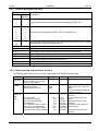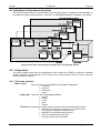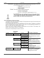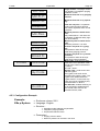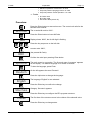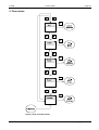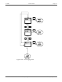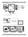
1
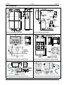
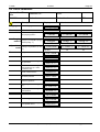
User's manual Pressurized enclosure system F 850S Software version 2.05 - manual rev.1 F 850S Table of contents Page 2 ° Contents 1 1.1 1.2 2 GENERAL ........................................................................................................................................................3 General safety guidelines .............................................................................................................................3 Safety Guidelines for explosion proofed devices .........................................................................................4 INTRODUCTION: PRESSURIZED ENCLOSURE SYSTEM F 850S .............................................................5 2.1 Explosion protection: pressurized enclosure................................................................................................5 2.2 Pressurized enclosure system according EN50016, second release (5/1996) ...........................................5 2.3 Pressurized enclosure system F 850S .........................................................................................................5 2.3.1 Mode pressurization using leakage compensation ...............................................................................5 2.3.2 Mode pressurization using Continuous flow..........................................................................................6 2.3.3 F 850S -Application using „Containment Systems“...............................................................................7 2.4 Peripherals....................................................................................................................................................7 2.4.1 Operating panels ...................................................................................................................................7 2.4.2 Disconnector unit SR852 and SR853 ...................................................................................................7 3 INSTALLATION AND CONNECTION.............................................................................................................8 3.1 Mounting .......................................................................................................................................................8 3.1.1 Control unit FS 850S .............................................................................................................................8 3.1.2 Solenoid valves .....................................................................................................................................8 3.1.3 Operating panels BT 8xx.x ....................................................................................................................8 3.1.4 Disconnector unit SR 852......................................................................................................................8 3.2 Connecting and Commissioning...................................................................................................................9 3.2.1 Terminal description FS 850S .............................................................................................................10 3.2.2 Commissioning and parameter defaults..............................................................................................10 3.2.3 Reset ...................................................................................................................................................11 3.2.4 Purging process...................................................................................................................................11 3.3 Maintenance ...............................................................................................................................................11 3.4 Repairs........................................................................................................................................................11 4 OPERATION ..................................................................................................................................................12 4.1 Display ........................................................................................................................................................12 4.2 Keyboard.....................................................................................................................................................12 4.3 How to enter and leave the bypass mode ..................................................................................................13 4.4 Indications during normal operation ...........................................................................................................14 4.5 Configuration ..............................................................................................................................................14 4.5.1 The menu structure .............................................................................................................................14 4.5.2 Description of the menu items.............................................................................................................15 4.5.3 Configuration Example ........................................................................................................................16 4.6 Alarm and malfunction indications..............................................................................................................19 5 FLOW CHARTS.............................................................................................................................................20 6 APPENDIX .....................................................................................................................................................25 6.1 6.2 6.3 6.4 6.5 Tables .........................................................................................................................................................25 Technical Details ........................................................................................................................................25 Block diagrams ...........................................................................................................................................26 Dimensions .................................................................................................................................................27 List of Parameters.......................................................................................................................................28 Gönnheimer Elektronic GmbH phone: +49 (6321) 49919-0; fax: -41 Email: [email protected] F 850S Safety Guidelines Page 3 1 General The symbols WARNING, CAUTION, NOTE This symbol warns of a serious hazard. Failure to observe this warning may result in death or the destruction of property. This symbol warns of a possible failure. Failure to observe this caution may result in the total failure of the device or the system or plant to which it is connected. This symbol highlights important information. 1.1 General safety guidelines To ensure safe and reliable operation, the notes and warnings contained in this manual must be observed. Caution, this device uses mains voltage! Failure to observe these warnings may result in serious personal injury or damage to property. The commissioning of this device may only be carried out by technically qualified personnel who must observe local safety regulations. Gönnheimer Elektronic GmbH phone: +49 (6321) 49919-0; fax: -41 Email: [email protected] F 850S 2 Introduction: Pressurized enclosure system F 850S Page 4 1.2 Safety Guidelines for explosion proofed devices Application and Standards This instruction manual applies to explosion protected control panels of type of protection types below. This apparatus is only to be used as defined and meets requirements of EN 60 079 particularly EN60 079-14 "electrical apparatus for potentiality explosive atmospheres". It can be used in hazardous locations which are hazardous due to gases and vapours according to the explosion group and temperature class as stipulated on the type label. When installing and operating the explosion protected distribution and control panels the respective nationally valid regulations and requirements are to be observed. General Instructions Work on electrical installations and apparatus in operation is generally forbidden in hazardous locations, with the exception of intrinsically safe circuits. In special cases work can be done on nonintrinsically safe circuits, on the condition that during the duration of such work no explosive atmosphere exists. Only explosion protected certified measuring instruments may be used to ensure that the apparatus is voltage-free. Grounding and short circuiting may only be carried out, if there is no explosion hazard at the grounding or short circuit connection. The control panel has to have a back-up fuse as stipulated. The mains connection must have a sufficient short circuit current to ensure safe breaking of the fuse. To achieve an impeccable and safety device operation, please take care for adept transportation, storage and mounting, as well as accurate service and maintenance. Operation of this device should only be implemented by authorised persons and in strict accordance with local safety standards. The electrical data on the type label and if applicable, the "special conditions" of the test certificate DMT 99 ATEX E 003 is to be observed. ! For outdoor installation it is recommended to protect the explosion protected distribution and control panel against direct climatic influence, e.g. with a protective roof. The maximum ambient temperature is 40°C, if not stipulated otherwise. Terminal compartment in Increased Safety When closing, it is to be ensured that the gaskets of the terminal compartment remain effective, thus maintaining degree of protection IP 54 to DIN 40 050. Unused entries are to be closed off by impactproof stopping plugs, which are secured against self-loosening and turning. Maintenance Work The gaskets of EEx e- enclosures are to be checked for damages and replaced, if required. Terminals, especially in the EEx e chamber are to be tightened. Possible changes in colour point to increased temperature. Cable glands, stopping plugs and flanges are to be tested for tightness and secure fitting. Intrinsically Safe Circuits Erection instructions in the testing certificates of intrinsically safe apparatus are to be observed. The electrical safety values stipulated on the type label must not be exceeded in the intrinsically safe circuit. When interconnecting intrinsically safe circuits it is to be tested, whether a voltage and/or current addition occurs. The intrinsic safety of interconnected circuits is to be ensured. (EN 60079-14, section 12) Gönnheimer Elektronic GmbH phone: +49 (6321) 49919-0; fax: -41 Email: [email protected] F 850S 2 Introduction: Pressurized enclosure system F 850S Page 5 2 Introduction: Pressurized enclosure system F 850S 2.1 Explosion protection: pressurized enclosure The use of pressurized enclosures allows the operation of ‘non explosion protected’ devices in hazardous areas inside zone 1 and zone 2. The protection type ‘pressurisation’ is based on the principle of maintaining a constant pressure using air or a protective gas to prevent an explosive mixture forming near the device inside the pressurized enclosure. Before start-up, the pressurized enclosure must be purged with air or protective gas to remove any explosive mixture that may be inside the enclosure. 2.2 Pressurized enclosure system according EN50016, second release (5/1996) According EN50016 second release from May 1996 is only those pressurized enclosure system allowed, which is safety examined according EN 954-1. The FS 850 S reaches the category 3 according EN 954-1 [4] (single fault evaluation). That means that a single arbitrary fault can occur without losing the safety functionality. 2.3 Pressurized enclosure system F 850S The pressurized enclosure system F 850S contains at least the control unit FS 850S and a solenoid valve. Each can be mounted in- or outside the enclosure. Furthermore several remote controls (operation panels) are available to improve ease of operation. It is also possible to connect intrinsically safe sensors to the control unit FS 850S. The pressurized enclosure system F 850S operates in two different modes: Pressurization using leakage compensation and Pressurization using continuous flow of protective gas. 2.3.1 Mode pressurization using leakage compensation After purging, the control unit FS 850S holds the pressure inside the enclosure at a minimum of 0,8 mbar. Two different solenoid vale techniques are available: digital working solenoid valve (DSV) technique or proportional working solenoid valve (PSV) technique. a) Digital solenoid valve technique While purging, the DSV is activated and a large amount of purge medium flows inside the enclosure through a nozzle with a large cross-section. After purging, the control unit turns off the DSV. The leakage compensation is made by a bypass choke, with a very small adjustable crosssection (diameter 0,3 ...1 mm), inside the valve. The protective medium that flows into the enclosure now is adequate to maintain a pressure of at least 0,8 mbar. The pressure is monitored by the control unit FS 850S. The maximum and minimum pressure of the enclosure is programmable. For purging, a traditional and a new integrating method are available: 1. Using the traditional method the purge quantity is a product of a pre-set minimum of flow rate and time. The flow rate depends on the size of the internal nozzle (diameter 1 ...6 mm) of the valve and can be specified by matched charts. The common rule of purging must be considered: let in minus leakage loss is bigger than flow minimum. This purging method is called as time based purging method. 2. In contrast to the traditional one the integrating purging method measures the real volume flow through the enclosure outlet and adds it up to get the real purge volume. Also, the flow rate is monitored, depending on the size of the plate orifice of the control unit. If the flow rate sinks below its minimum, it will be ignored and it will not contribute to volume integration. Therefore we achieve a safe and economical purging method. See also Figure_1. Gönnheimer Elektronic GmbH phone: +49 (6321) 49919-0; fax: -41 Email: [email protected] F 850S 2 Introduction: Pressurized enclosure system F 850S Page 6 Pressure inside the enclosure will be observed by each purging method. The digital solenoid valve technique has a considerable disadvantage: during purging process and normal operation, a constant rate of protective gas is needed. For safety reasons the rate must be larger than leakage rate of the enclosure. Wasting protective gas causes high costs in many applications. Figure 1: Consumption of protective gas b) Proportional solenoid valve technique Using proportional solenoid valve technique prevents unnecessary wasting protective gas. The internal proportional working sensory equipment and a proportional valve as actuator are combined to a pressure feedback control system. The benefits of pressure feedback control are: 1. Considerable less consumption of protective gas - additional costs for proportional valve will be amortised soon 2. Increased service reliability achieved by constant pressure inside enclosure - increasing leakage caused by e.g. ageing of the enclosure will be balanced and sudden failure is prevented 3. Almost no flow noise and only a small protective gas consumption using a solid enclosure Another advantage using a proportional solenoid valve is; that pressure control is also used during purging. A set-point pressure will be achieved in the enclosure, while the flow volume, that leaves the enclosure, will be recorded and integrated through time, until the required purge volume is achieved. Advantages of this method are: 1. A definite pressure while purging - pressure sensitive parts of the enclosure, like membrane switch panels or windows, will not be overloaded. 2. Purge volume accuracy is achieved by integration of the purge medium flow volume at the outlet. Wasting purge medium is no more a topic of today. 2.3.2 Mode pressurization using Continuous flow The control unit FS 850S incorporates the operation mode „continuous flow“. This operation mode is necessary, for example if an analyser produces an explosive atmosphere inside the enclosure (containment system). The operation mode continuous flow flushes the enclosure permanently. After the (pre-) purging procedure (purging process) a set-point flow rate is adjusted during normal operation. The monitored flow rate minimum is adjustable. The continuous flow operation mode can be realised using 2 digital solenoid valves as well as using one proportional solenoid valve. Gönnheimer Elektronic GmbH phone: +49 (6321) 49919-0; fax: -41 Email: [email protected] F 850S 2 Introduction: Pressurized enclosure system F 850S Page 7 2.3.3 F 850S -Application using „Containment Systems“ „Containment Systems“ are defined as parts of a device within a pressurized enclosure, which could emit combustible gas (or occasionally an explosive environment: zone 1, explosive mixture) from within the enclosure. In order to receive an EEx p-System including a „Containment System“, which is failsafe according EN 50016, with the attribute 'no emission', the following conditions must be met: 1. The flammable substance inside the containment system is in the gas or vapour phase when operating between the specified temperature limits 2. The minimum pressure specified for pressurized enclosure is at least 50 Pa higher than the maximum pressure specified for the containment system 3. An automatic safety device initiates, if the pressure difference falls below 50 Pa. This automatic safety device can be activated by a difference pressure switch, looped into the external alarm loop (terminal 4/10 on FS 850S). If an alarm occurs on this loop, the control device FS 850S will turn off the ignition-capable device immediately. After alarm cancelling the control device FS 850S starts operation automatically with the purging procedure. The external alarm loop is made by a normal closed connection method. 2.4 Peripherals 2.4.1 Operating panels For the control unit FS 850S several operating and visualising panels are available. These panels consist of the explosion protection class 'intrinsically safe' and are considerably advantageous, particularly when the control unit is mounted inside the enclosure. 1. Common operating panels: BT 854.1 and BT 855.1 with • On/Off-Switch • Key-operated switch for bypass • LED-indicator for READY and ON The connection to the control unit consists of 6 wires. 2. Intelligent operating panel type BT 851 This operation panel indicates operation and malfunction reports as plain text. The 4 membrane switches offer total command of the control unit. Status, momentary pressure, flow rate as well as remaining purge time are always available. The connection to the control unit consists of only 3 wires. 2.4.2 Disconnector unit SR852 and SR853 According to EN 50016 all non- intrinsically safe connections of the ignition capable apparatus must be disconnect, if the protection gas pressure falls below the safety limit. In many applications more than the two connector terminals on the control unit FS 850S are needed. In these cases the disconnector unit SR 852, with 8 respectively 16 galvanically separated connectors, is considerable helpful. The S853 provides a switching power of 250V , 16 A. Gönnheimer Elektronic GmbH phone: +49 (6321) 49919-0; fax: -41 Email: [email protected] F 850S 3 Installation Page 8 3 Installation and connection This Chapter contains important steps for mounting, connecting and starting. 3.1 Mounting 3.1.1 Control unit FS 850S The control unit FS 850S can be placed inside a hazardous area. The location (inside or outside the enclosure) as well as the position is almost arbitrary. Only intake and outlet of the control unit should be lined up on a horizontal axis. See also Figure 12 in the Appendix. The control unit has 4 holes on the rear plate for mounting, although fixing only with the screw connection of intake or outlet is sufficient. The solenoid valve(s) and the control unit (respectively pressure monitor) should be mounted on the enclosure as far away from each other as possible (E.g. space diagonal arrangement), to achieve a total purging. Observe local safety guidelines and the regulative DIN EN 60079-14. 3.1.2 Solenoid valves The solenoid valves can be mounted inside or outside the enclosure. For mounting position see manufacturer's guide. 3.1.3 Operating panels BT 8xx.x ° Operating panel BT 851.0 The Operating panel BT 851.0 is mounted, without rear plate, directly on the enclosure. For mounting and bushing of the wire, several holes must be made. For location and drill size see Figure 13: Dimensions and template BT 851in appendix. ° Operating panel BT 851.5 The operating panel BT 851.5 has housing with environment protection IP 65. It can be located anywhere in hazardous area zone 1. For location and drill size see Figure 13: Dimensions and template in appendix. ° Operating panel BT 814.x The operating manual BT 814.x consists only of 2 LEDs and an ON/OFF-switch, directly fixed on the enclosure. The BT 814.1 has an additional key-operated switch for bypass. For location and drill size see Figure 14: Dimensions BT 855, template BT 854 in appendix. ° Operating panel BT 815.x The operating panel BT 815.5 has housing with environment protection IP 65. It can be located anywhere in hazardous area zone 1. For location and drill size see Figure 14: Dimensions BT 855, template BT 854 in appendix. 3.1.4 Disconnector unit SR 852 The disconnector unit SR 852 can be mounted and operated in hazardous area zone 1. It represents an Ex-e terminal box. Gönnheimer Elektronic GmbH phone: +49 (6321) 49919-0; fax: -41 Email: [email protected] F 850S 3 Installation Page 9 3.2 Connecting and Commissioning After mounting, connect the 'intrinsically safe' peripherals to terminal 1-10, and the power supply, valves and ignition-capable apparatus to increased safety terminals of the control unit. LINE VOLTAGE ! Extreme caution is advised when handling this device. High electrical discharge is possible and can be fatal. Please note the following Standard of Compliance: DMT 99 ATEX E 003 and the regulative DIN EN 60079-14. Do not exceed terminal safety limits of each terminal. See limits in technical details or declarations of conformity. Figure 2: Blockdiagram FS850S If the BT854.1 or BT855.1 operator panel is being used, the bypass function can be activated via an external key switch. In this case set the bypass code to 9999 to prevent a secondary bypass function by bypass code directly from the control unit. The key switch is to be connected to terminals 4 and 5 of the control unit. If external operation panels BT 81x or additional pressure monitor are not used, it is possible to connect terminal 4 and 6 of the control unit FS 850S to a shorting bridge, to enable an automatic switch after purging process. In this case, the On/Off-function of the far left button on the control unit FS 850S is non- operational. Gönnheimer Elektronic GmbH phone: +49 (6321) 49919-0; fax: -41 Email: [email protected] F 850S 3 Installation Page 10 3.2.1 Terminal description FS 850S Terminal FS850S BT 85x Description SR 852 1 2 3 4 5 6 7 8 9 4 10 11,12 13,14 15,16 17,18 19,20 21,22 23,24 25,26 1 2 3 Terminals exclusively for connecting the operating panel BT 851 4 5 6 7 8 9 Terminals of operating panel BT 813, BT 814 and BT 815 External alarm loop (intrinsically safe), opening circuit alarms EEx p-System and switching off ignition-capable device. Working current circuit 1 Working current circuit 2 Line voltage, either neutral conductor at AC or minus pole at DC Line voltage, either outer conductor at AC or plus pole at DC Terminals for proportional solenoid valve Terminals for additional digital solenoid valve 2 Terminals for digital solenoid valve 1 Terminals for solenoid valve fuse inside FS 850S + + ,+,+,- 3.2.2 Commissioning and parameter defaults The following parameters are pre-set after connecting the FS850S to mains supply: Structure Codes Pressure and flow Parameter Display Text Mode: leakage compensation Purging method: time based Type of valve: digital Main menu (M-Code) Bypass (By-Code) On/Off-Code (On/Off-C.) 0001 0002 0000 The setting 0000 disables the coding (not in the case of M code) The setting 9999 switches off bypass by coding 10 [min] time based purging method selected 500 [l] integ. purging method se1 [l/s] lected 0,5 [l/s] time based purging meth. 2,0 [l/s] selected 0,8 [mbar] operation mode continuous 15 [mbar] flow selected 10 [mbar] 2 [mbar] proportional solenoid valve selected Purging time 00-10-00 Purging volume Min. flow while purging Min. flow while operating Flow set-point Min. pressure inside enclosure Max. press. inside enclosure Set-point press. while purging Set-point press. while operating Gönnheimer Elektronic GmbH 500.0 1.0 0.5 2.0 0.8 15.0 10.0 2.0 phone: +49 (6321) 49919-0; fax: -41 Comment Email: [email protected] F 850S 3 Installation Page 11 3.2.3 Reset Press red bottom (ENTER-Button)* while switching on the control unit FS 850S to reset all parameters to the values in table above. *: used only on control unit FS 850S. RESET 3.2.4 Purging process The control unit FS 850S starts the purging process immediately after start up, providing the programmed minimal pressure (minimum 0.8 mbar) is present. Parallel to pressure monitoring, the flow rate will be watched, to get a safe purging process. If the purging flow rate passes its minimum (e.g. temporary shut at the outlet), then the purging process will be interrupted and the control unit continues purging, after the disturbance is gone. But if purging pressure exceeds the min or max limits then the purging process will be terminated and the control unit will start a new purging process automatically after achieving purging condition. The table below shows the minimum flow rate in accordance of the used plate orifice. Plate orifice in control unit Minimum flow rate 0,07 liter /sec. ∅ = 4 mm ∅ = 6 mm 0,15 liter/sec. ∅ = 10 mm 0,35 liter/sec. ∅ = 14 mm 0,85 liter/sec. ∅ = 18 mm 1,25 liter/sec. 3.3 Maintenance Depending upon purity of the assigned purging air the inlet and outlet opening of the FS850S must regularly on impurities (e.g. oil, dust, etc) or corrosion to be examined. In case of serious impurities the operator should weigh the possibility of a punctual appropriate cleaning by Gönnheimer Elektronic GmbH in relation to a spontaneous loss of the controller. 3.4 Repairs Repairs of the controller as well as the accessories may be made only by the Gönnheimer Elektronic GmbH. Gönnheimer Elektronic GmbH phone: +49 (6321) 49919-0; fax: -41 Email: [email protected] F 850S 4 Operation Page 12 4 Operation The user has total control of the purging system F 850S by the use of 4 keys on the control unit FS 850S respectively by using the external operating panel BT 851. Operation on control unit FS 850S panel BT 851 is equal. Using the other operating panels only a restricted operation is possible. 4.1 Display The built-in display indicates operation modes, present pressure or flow rate data, as well as malfunction. 4.2 Keyboard The four multi-functional keys have different meanings and functions depend on the present operation mode. Key Ein/Aus „Shift right“button BYPASS Mode Function normal operation Toggles the ignition-capable device on and off, if purging system state is ready running menu Shift cursor one position right. normal operation Activates Bypass. Fire certificate required ! „Up“-button running menu INFO /P/Q/T normal operation „Down“-button MENU „Enter“-button running menu normal operation running menu Gönnheimer Elektronic GmbH Get menu next item Changes indication of the display: present pressure, flow rate, remaining purge time respectively purge volume and present state of the purging system Get previous menu item Executes main menu Initiates and confirms parameter input phone: +49 (6321) 49919-0; fax: -41 Email: [email protected] F 850S 4 Operation Page 13 4.3 How to enter and leave the bypass mode Utilise bypass only, if it is sure that no explosive atmosphere is inside the cabinet! Fire certificate required ! The bypass mode is denied, if it is possible that a explosive atmosphere can arise inside the EEx p- housing ! The origin state is normal operation, the EEx p housing can be purged, unpurged or while purging. The steps shown below are according to the control device FS850 not to the operation panel BI851.x. If you have a operation panel BT81x.1 use the key switch instead. By-CODE 0002 The bypass code is needed The ex works Bypass code is ‘0002’. Enter is right code using the arrow keys and confirm with the ENTER- key. Bypass Or On The bypass mode is now active. If the control unit is set to “automatic on” the display shows “bypass” and “On” alternately and the relay contacts (Ter. 11,12 and 13,14) are closed. Now you can toggle the relay contacts by pressing the “right-“ button. Remark: if the E/A- code is unequal to zero, you must enter them each time you want to change the relay contacts state. Leave the bypass mode in the same way as enter. Gönnheimer Elektronic GmbH phone: +49 (6321) 49919-0; fax: -41 Email: [email protected] F 850S 4 Operation Page 14 4.4 Indications during normal operation The info-indication shows the present state of the purging system. In addition to this indication, it is possible to select current pressure-, flow rate-, or remaining purge time- indication. See below: Figure 3 Flow chart: state of purging system and corresponding display 4.5 Configuration You must configure and enter the parameters of the control unit FS850S to achieve a desired mode of operation. All parameters of the control unit are structured in form of a menu. See also the flow charts in chapter 5. 4.5.1 The menu structure Main menu Language Structure Gönnheimer Elektronic GmbH The main menu is sub-divided into 4 separate categories: • • • • Language Structure Parameters Codes These are the 5 languages available: • • • • • German English French Dutch Spanish Selecting a purging system structure with the following alternatives: • • • • • Operation mode leakage compensation or continuous flow Using digital or proportional solenoid valves Integration or time based purging method Using an additional pressure monitor Using the disconnector unit SR852 phone: +49 (6321) 49919-0; fax: -41 Email: [email protected] F 850S 4 Operation Parameters This category contains the necessary parameters depending on the structure defined above. Examples for parameters are: • • • • Codes Page 15 Purging time Minimum flow while purging process Minimum pressure Maximum pressure The control unit has 3 different code words: • M-Code: to enter main menu • By-Code: to activate Bypass • E/A-Code: to switch ignition-capable apparatus on or off The FS850S does not working during running main menu. - That means the solenoid valves and the ignition capable device inside the cabinet are switched off. 4.5.2 Description of the menu items The display of the control unit has only 8 digits. For this purpose the names of the structures and parameters are often abbreviations. In the following table below are some explanations of the menu items. The table as a reference guide for programming the desired system structure and to set the appropriate parameters correctly. The menu items are roughly sorted by class. Please note that the viewable conditions of parameters are not included. The category ‘Language’ is also excluded, because of it's simplicity. See also the corresponding flow charts in section 5. Hierachy 1.Level Structure 2.Level 3.Level Valves P-Valve D-Valve Integra. Integ. Y Integ. N. Cont.Flow C. Flow Y. C. Flow N. Param. Gönnheimer Elektronic GmbH Pur. Time ............................... phone: +49 (6321) 49919-0; fax: -41 Description, Explanation Selecting 'valves’ on level 2 means that a proportional solenoid valve or a digital solenoid valve is available on level 3 Integration purging method, Yes Configures integration purging method. Integration Purging method, No Selects time based purging method. Continuous Flow, Yes Activates the operation mode ‘continuous flow'. Continuous Flow, No Activates the operation mode ‘leakage compensation’. Purge time - Enter a fixed purge time in h/min/sec. The purge time only appears, if the time based purging method is chosen. Email: [email protected] F 850S 4 Operation Codes Page 16 Pur. Vol. ................................ Min.Fl. P. ................................ Min.Fl .O. ................................ Minimum flow rate during operating Rated Fl. ................................ Min.Pres. ................................ Max.Pres. ................................ R. Pre. Pu. ................................ Rated Pr. ................................ M-Code ................................ By-Code ............................... On/Off-C. ................................ Flow rate set-point - In operation mode ‘continuous flow’ this flow rate will be regulated, while normal operation. Minimum pressure inside enclosure Only values above ≥ 0.8 mbar can be entered. (Additional safety regulativ to EN 50016) Maximum pressure inside enclosure Maximum pressure ≤ 18 mbar Pressure set-point during purging, This pressure value will be regulated during purging process. Pressure set-point during normal operation, This pressure value will be regulated during normal operation. Menu code - Code word to enter main menu out of operation mode. The M-code could not switched of by setting M-Code =„0000“ . Bypass code - Code word to activate the bypass. The bypass code word can be switched off by setting „0000“. The bypass code „9999“ blocks the bypass function. In that case a bypass can only be activated by keyoperated switch on BT 81x. On/ Off code, enables switching on or off the ignition-capable device. The On/Off code word can be switched off with „0000“. Purge volume - The purge volume only appears, if integration purging method is chosen. Minimum flow rate during purging process 4.5.3 Configuration Example ExampleEEx p-System ⇒ Enclosure volume: 500 l ⇒ Language : English ⇒ Structure : • Operation mode: leakage compensation • Integration purging method • Proportional solenoid valve ⇒ Parameters • Purging volume: 2500 l • Minimum pressure of enclosure: 0.8 mbar Gönnheimer Elektronic GmbH phone: +49 (6321) 49919-0; fax: -41 Email: [email protected] F 850S 4 Operation Page 17 • Maximum pressure of enclosure: 12 mbar • Set-point pressure purging process: 10 mbar • Set-point pressure normal operation: 1.5 mbar ⇒ Codes • M- Code: 0001 • By-Code: 0002 • E/A-Code: 0000 (switch off) Procedure: Press the Enter-button to start main menu. The control unit calls for the M-code to be entered. M-Code The ex works M-code is ‘0001’. Press the Enter-button to insert M-Code. _000 Display shows ‘0000’, the far left digit is flashing. Press the key sequence on the left side to enter code ‘0001’, 0001 (the present M-Code). Confirm the code input pressing Enter-button Sprache The main menu is now active. The first sub menu ‘Language’ appears on the display. The default language of ex works is German. To alter the language, press Enter. Deutsch On the left appears the word ‘Deutsch’ Press the Up-button to change the language. English The language ‘English’ is now selected. Press the Enter-key to confirm the change. Structure Category ‘Structure’ appears. Press the Enter-key to configure the EEx p-system structure. Valves The first item of the structure menu is the choice of the solenoid valve. Press the Enter-key to change state. Gönnheimer Elektronic GmbH phone: +49 (6321) 49919-0; fax: -41 Email: [email protected] F 850S 4 Operation D-Valve Page 18 The present state is digital solenoid valve. Change the state by pressing Up-key - P-Valve The new state is now ’Proportional solenoid valve’. Confirm the change by pressing Enter-key. Cont.Flow This item is the operational mode 'continuos flow' or 'leakage compensation'. The ex works state is already 'leakage compensation' therefore: skip this item by pressing the Up- key. Param. The structure menu is now finished. The main menu continues automatically with the pre-selected parameters. Start the parameter category by pressing the Enter- key. Pur. Vol. The first menu item ‘Purging volume’ appears. Press the Enter- key to enter the desired volume ‘2500 l’. _00500 l Expecting a pre-set purging volume of 500 l, the input sequence is as follows: 00_500 l 002500 l Confirm the input by pressing the Enter- key. Min Fl. P. The minimum flow while purging can be increased for special applications. In this case leave the default Min.Pres The desired minimum pressure of 0.8 mbar is already adjusted ex works. Continue skipping this menu item by pressing the Up- key or view by pressing the Enter- key. Now enter the desired value of the maximum pressure. Modify the present parameter as shown above. Max.Pres. 012.0mbar The desired maximum pressure is 12.0 mbar. R. Pre. Pu The desired set-point pressure during the purging process of 10.0 mbar is already adjusted ex works. Continue passing this menu item by pressing the up- key. Gönnheimer Elektronic GmbH phone: +49 (6321) 49919-0; fax: -41 Email: [email protected] F 850S 4 Operation Page 19 Rated Pre. The desired set-point pressure during normal operation must be adjusted. Modify the present parameter to 1.5 mbar as shown above. Codes The parameter category is now finished. The main menu continuous automatically with the sub menu codes. M-Code Modify M-Code to ‘0001’ as shown above. Please note: the M-Code cannot be set to ‘0000’. By-Code Modify By-Code to ‘0002’ as shown above. On/Off-C. Set the On/Off-Code to switch the ignition-capable apparatus on or off to ‘0000’. This code word is from now on disabled. End The main menu settings are now complete. After pressing the Enter- key, the purging system is in operation state. 4.6 Alarm and malfunction indications Alarm Ext.Alar Error message Error E. Error P. Error F. Error C. Gönnheimer Elektronic GmbH Cause Actions The external alarm occurred, i.e. the Fix shorting bridge to terminal 4 external alarm loop is broken. If the and 10 of the control unit FS external alarm loop is not used, dis- 850S. able the external alarm loop by a shorting bridge. Cause Remedy EEPROM Read Error Stored configuration data is incomplete or corrupt. Pressure sensor Error The integrated pressure sensors do Turn FS 850S off. Turn FS 850S not work properly on. If the error message occurs again, flow sensor Error then return the control unit FS The integrated flow sensors do not 850S to Gönnheimer Elektronic. work properly Hardware - fault phone: +49 (6321) 49919-0; fax: -41 Email: [email protected] F 850S 5 Flow charts Page 20 5 Flow charts Figure 4 Flow chart main menu Gönnheimer Elektronic GmbH phone: +49 (6321) 49919-0; fax: -41 Email: [email protected] F 850S 5 Flow charts Page 21 Figure 5 Flow chart language menu Gönnheimer Elektronic GmbH Tel.:(06321) 1 20 31 - 1 20 32 Fax.:(06321) 1 69 73 F 850S 5 Flow charts Page 22 Figure 6 Flow chart structure category Gönnheimer Elektronic GmbH phone: +49 (6321) 49919-0; fax: -41 Email: [email protected] F 850S 5 Flow charts Page 23 Figure 7 Flow chart parameter category Gönnheimer Elektronic GmbH phone: +49 (6321) 49919-0; fax: -41 Email: [email protected] F 850S 5 Flow charts Page 24 Figure 8 Flow chart code category Gönnheimer Elektronic GmbH phone: +49 (6321) 49919-0; fax: -41 Email: [email protected] F 850S 6 Annex Page 25 6 Appendix 6.1 Tables plate orifice size Plate orifice Pressure [bar] [105Pa] 1,5 2 2,5 3 3,5 4 4,5 The right diameter of the plate orifice depends upon the desired volume flow rate on the enclosure outlet and the built in nozzle of the solenoid valve. Flow rates into enclosure depend upon primary pressure and nozzle diameter. Flow rate is about [m3/h] 0,5 ... 1,1 1,1 ... 2,7 2,5 ... 6,5 6 ... 11 9 ... 15 [mm] 4 6 10 14 18 Flow rate [l/s] ρ Air = 1,293 kg/m3 Nozzle diameter [mm] 0,3 0,5 0,7 1 0,0275 0,076 0,149 0,304 0,0338 0,094 0,184 0,374 0,0391 0,109 0,213 0,433 0,0438 0,0121 0,238 0,484 0,048 0,133 0,261 0,53 0,0518 0,144 0,282 0,573 0,0554 0,154 0,301 0,612 1,5 0,693 0,838 0,968 1,063 1,195 1,28 1,367 2 1,208 1,48 1,708 1,908 2,087 2,252 2,404 3 2,676 3,27 3,759 4,186 4,569 4,917 5,239 4 4,653 5,651 6,471 7,177 7,804 8,37 8,883 5 7,06 8,511 9,685 10,682 11,554 12,33 13,032 6 9,796 11,098 13,199 14,445 15,511 16,441 17,263 6.2 Technical Details Control unit FS 850S General Housing Electrical specifications Mounting Ex-protection class Environment protection Dimensions Material Power consumption Main voltage Working circuits Terminal 11, 12, 13, 14 Control circuits Terminal 1..10 Pneumatic Mounting EEx p Configuration Pressure range Flow rate range Position Environment temperature Parameter input Storage Gönnheimer Elektronic GmbH inside hazardous area E Ex e m [ib] IIC T6 IP 65 (Remark: without outlet drill) H x W x D: 220 mm x 120 mm x 90 mm Aluminium, lacquered / Ral 7035 About 2.5 VA (without peripherals) 24VDC, 24VAC, 110VAC, 120VAC, 220VAC, 230VAC 48 ...62 Hz AC: U ≤ 250VAC, I ≤ 5A at cos ϕ > 0,7 DC: U ≤ 30 VDC, I ≤ 5 A, P ≤ 150 W Ex protection class: intrinsically safe E Ex ib IIC see declaration of conformity for further details DMT 99 ATEX E 003 0 ... 18 mbar 3 0,5.. 15 m /h, dependent upon plate orifice size position independent, only intake and outlet of the control unit should be lined up on a horizontal axis. -10°C ...+50°C at T6 -10°C ...+60°C at T4 LC-Display, menu guided Different languages : German, English, French, Dutch, Spanish by EEPROM double saved with CRC Tel.:(06321) 1 20 31 - 1 20 32 Fax.:(06321) 1 69 73 F 850S 6 Annex Page 26 6.3 Block diagrams Figure 9 Electrical block diagram Figure 10 Pneumatic block diagram Gönnheimer Elektronic GmbH phone: +49 (6321) 49919-0; fax: -41 Email: [email protected] F 850S 6 Annex Page 27 6.4 Dimensions Figure 11: Dimensions FS 850S Figure 12: Mounting examples Figure 13: Dimensions and template BT 851 Figure 14: Dimensions BT 855, template BT 854 Figure 15: Dimensions digital solenoid valve Gönnheimer Elektronic GmbH Figure 16: Dimensions proportional solenoid valve phone: +49 (6321) 49919-0; fax: -41 Email: [email protected] F 850S 6 Annex Page 28 6.5 List of Parameters System identification Installation no.: Date: FS 850S. . Production no.: Solenoid valve Inputs Description Language F850S language Display Value/ state Language Structure Valve Solenoid valve type used with this purging system? Valves P-Valve D-Valve Integ. Y. Integ. N. C. Flow Y. C. Flow N, Tick box Purging Time based purging method method (Integ N.) or integration purging method (Integ. Y.) N.) Cont. Flow Tick box Purge time Pur. Time Purge volume Codes Integra. Tick box Operational Continuous flow (C. flow Y.) or mode leakage compensation (C. flow Parameters Pur. Vol. Minimum flow rate during purging procedure Min. Fl. P. Minimum flow rate during normal operation by op. mode continuous flow Set-point flow rate by operation mode continuous flow Min.Fl. O. Pressure monitor, minimum pressure Min. Pres. Pressure monitor, maximum pressure Max. Pres Set-point pressure during purging R. Pre. Pu. Set-point pressure during normal operation Rated Pr. Code for main menu M-Code Code for bypass By-Code Code to enable switching ignition-capable device On/Off-C. Gönnheimer Elektronic GmbH BT 8 Rated Fl. phone: +49 (6321) 49919-0; fax: -41 Email: [email protected] ' ) * + , ( - * 1 ! 6 + . / . "4 . 7 $0123 5 67-(( 8 ; < " & 9 : ) * 0 ! ! & , " 8 2'10 '??-= 3 A * + BB # $ %# ? + &= > / = ?-@?@ * * = 8 CD3 %% ?? )221 " ? & 3 A * . 8 12 2'-.'??) D 8 12 2'6.'??1 D 8 12 2'?.'??- D 8 12 2)2.'??- D 8 12 2)0.'?07 D 8 ?1- '. '??6 3 '2 B 2'72@2'7' 2'72@2'7' 2'72@2'7' 2'72@2'7' 2'72@2'7' '@( ?(@1@?6 6@( ?6 7@- ?6 ?@7 00 3 " B B ! HIJ E F G F 3 3 G F GF = * '' * ?-@?@ $ * * ') 5 * . ! " # $% & !' ( ))( *+, ,= ! > . ( */01 /02 -,/01 "$3 0 $ '??? / $ ! " # $ %# % & ' ( '( + '- K% A B$B + ! ?? + '1 '1 ' / I 8 22( $0123 '1 ) * / $0123 / 8 122'6.'??1 B $30123= $012 * C 01'= % C ?0 )7)(- + / 8 122'6.'??1 H ?1- ' H3 * / J 8 3 J ( '1 ( ! '1 )(2= ))2= ')2= ''2= )- D + 3 L M )1( D '0 )- D 3B012 )1@)6 D ! )'@)) )(@)- % ! '?@)2 A ''@') B '(@'- + L B M M M )12 D 1+ 2=7 L B % B M M M 3 3 (2 D 1+ '12 9 BB = . ! " # $ %# % & ) ( '=? ( 1= 6= '2 ) L2 B2 %2 <2 0=6' D 0=6' D 0=6' D 0=6' D " 1' + '2 + )2 + 6 + ''2 9 )) 9 -- 9 '( 9 '2 '2 '2 '2 + ' 2 & & & & ) N& ) N& ) N& ) N& '2 (71 D -1O 6 62O 1 '6 A 8 CD3 %% ?? )221 " '' '7 3 / = ! " # $ %# % & ( (