1
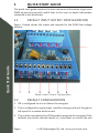
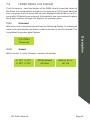
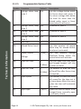
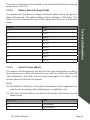
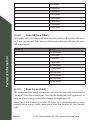
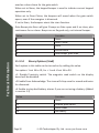
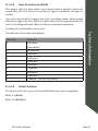
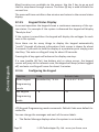
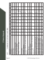
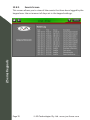
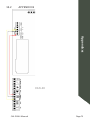
ZLM4 User Manual
J VA T E CH N O LO G I E S
www.jva-fence.com
CONTENTS
1
Quick Start Guide. . . . . . . . . . . . . . . . . 6
1.1
Default Input Output Configuration . . . . . . 1.2
Default Configuration. . . . . . . . . . . . . 1.3
Wiring up your ZLM4 . . . . . . . . . . . . . .
1.4Jumpers . . . . . . . . . . . . . . . . . . . .
1.5
Frequently Used LCD Keypad Commands . . . . 6
6
7
8
9
2Introduction. . . . . . . . . . . . . . . . . . . . 10
3
Features and Benefits . . . . . . . . . . . . 14
3.1
More Features . . . . . . . . . . . . . . . . 16
4Constraints . . . . . . . . . . . . . . . . . . . . 17
5Specifications. . . . . . . . . . . . . . . . . . . 18
6
Equipment Requirements/Options. . . . 20
6.1Requirements. . . . . . . . . . . . . . . . .20
6.2Options. . . . . . . . . . . . . . . . . . . .20
Contents
7Description. . . . . . . . . . . . . . . . . . . . . 21
7.1
Front Panel Status Lights. . . . . . . . . . .21
7.2
Status Light Codes . . . . . . . . . . . . . .22
7.3
Front Panel LCD Display . . . . . . . . . . . 23
7.3.1Disarmed . . . . . . . . . . . . . . . . . . .23
7.3.2Armed . . . . . . . . . . . . . . . . . . . . 23
7.3.3Alarms . . . . . . . . . . . . . . . . . . . .24
7.4
Keypad (Optional). . . . . . . . . . . . . . .24
7.5
Internal Beeper/Keypad Beeper . . . . . . . . 24
7.6
Arm input and magnetic key fob. . . . . . . . 24
7.7
Gate Input (control input 2). . . . . . . . . .25
7.8
Group Simultaneous Pulse Feature . . . . . . 25
7.9
Standby Battery . . . . . . . . . . . . . . . 25
8
Controlling your ZLM4 . . . . . . . . . . . 26
8.1
8.2
Control Arbitration. . . . . . . . . . . . . .26
Magnetic proximity switch . . . . . . . . . . .26
Page 2
© JVA Technologies Pty. Ltd. www.jva-fence.com
9Installation . . . . . . . . . . . . . . . . . . . . 32
9.1
9.3
9.4
Installation Steps . . . . . . . . . . . . . . 32
Fence Terminals. . . . . . . . . . . . . . . .34
Control, Power and IO Terminals. . . . . . . 35
10
Wiring Diagrams . . . . . . . . . . . . . . . . . 38
10.1
10.2
10.3
10.4
Standalone fence configurations . . . . . . .38
Low Voltage Zoning System. . . . . . . . . . 40
Keypad Bus Wiring. . . . . . . . . . . . . . .41
Example group wiring diagram. . . . . . . . .41
11
Technical Information. . . . . . . . . . . . . 42
11.1
11.2
11.2.1
11.2.2
11.2.3
11.2.4
11.2.5
11.3
11.3.1
11.3.2
LCD Error Messages. . . . . . . . . . . . . 42
Programming Options . . . . . . . . . . . . .42
Enter Programming Mode . . . . . . . . . . .42
To exit programming mode . . . . . . . . . . .42
Changing the installer PIN. . . . . . . . . . 43
Changing an Option. . . . . . . . . . . . . .43
Programmable Options Table . . . . . . . . . 44
Programming Options in Detail. . . . . . . . .46
Zone 1 Fence Voltage Alarm Level (01xx#). . . 46
Zone 2 Fence Voltage Alarm Level (02xx#). . . 46
JVA ZLM4 Manual
Contents
8.3
PC Control. . . . . . . . . . . . . . . . . .27
8.4
Web Server . . . . . . . . . . . . . . . . . .27
8.5Keypad . . . . . . . . . . . . . . . . . . . .27
8.6
Controlling the ZLM4 using the Keypad . . . .27
8.6.1
Keypad Versions. . . . . . . . . . . . . . . 27
8.6.2
Keypad Status Display. . . . . . . . . . . . .28
8.6.3
Arming/Disarming Using the Keypad . . . . . . 28
8.6.4
When an Alarm Occurs . . . . . . . . . . . . 29
8.6.5
To Silence an Alarm. . . . . . . . . . . . . .29
8.6.6
To Clear Alarm Memory . . . . . . . . . . . .29
8.6.7
Changing the PIN Number . . . . . . . . . . .29
8.6.8
Standby Battery . . . . . . . . . . . . . . . 30
8.6.9
Internal Beeper/Keypad Beeper . . . . . . . . 30
8.6.10
ZLM4 Relevant Keypad Codes . . . . . . . . .30
Page 3
Contents
11.3.3
11.3.4
11.3.5
11.3.6
11.3.7
11.3.8
11.3.9
11.3.10
11.3.11
11.3.12
11.3.13
11.3.14
11.3.15
11.3.16
11.3.17
Zone 3 Fence Voltage Alarm Level (03xx#). . . 46
Zone 4 Fence Voltage Alarm Level (04xx#). . . 46
Missed Pulse Count (06xx#). . . . . . . . . .46
Battery Alarm Voltage (07x#). . . . . . . . .47
Siren On Time (08x#) . . . . . . . . . . . . . 47
Siren Off Time (09x#) . . . . . . . . . . . . .48
Siren Cycles (10x#). . . . . . . . . . . . . .48
Input Type (11x#) . . . . . . . . . . . . . . .49
Input 2 Function (12x#). . . . . . . . . . . .49
Gate Delay (13x#). . . . . . . . . . . . . . .49
Chime mode (14x#) . . . . . . . . . . . . . . 49
Binary Options (16x#). . . . . . . . . . . . .50
Auto Re-Arm time (20x#). . . . . . . . . . . .51
Relay Functions. . . . . . . . . . . . . . . .51
Group Mode (26x#) . . . . . . . . . . . . . .53
12
Z-Series Keypads. . . . . . . . . . . . . . . . . 55
12.1
PTE0210 LCD Keypad . . . . . . . . . . . . .55
12.2
PTE0230 Touch Keypad . . . . . . . . . . . .56
12.3
LCD Keypad Operation. . . . . . . . . . . . .57
12.3.1
Wiring up your Z-Series LCD Keypad . . . . . .57
12.3.2
Keypad status LEDs. . . . . . . . . . . . . .57
12.3.3
Arming/Disarming Using the Keypad . . . . . . 57
12.3.4Menus . . . . . . . . . . . . . . . . . . . . 57
12.3.5
Keypad Status Display. . . . . . . . . . . . .58
12.3.6
Configuring the Keypad . . . . . . . . . . . .58
12.4
To Exit Keypad Programming. . . . . . . . . .60
12.5
Connecting Multiple Keypads . . . . . . . . . 60
12.6
Keypad Configuration Notes. . . . . . . . . .61
12.7
Summary Of Keypad Functions. . . . . . . . .62
12.8
Touch Keypad Operation. . . . . . . . . . . .64
12.8.1Screens . . . . . . . . . . . . . . . . . . . 64
12.8.2
Home Screen . . . . . . . . . . . . . . . . .64
12.8.3
Alarm Screen. . . . . . . . . . . . . . . . .65
12.8.4
Settings Screen . . . . . . . . . . . . . . . 66
12.8.5
Events Screen . . . . . . . . . . . . . . . . 70
Page 4
© JVA Technologies Pty. Ltd. www.jva-fence.com
12.8.6
12.8.7
Zones and Zone Details Screen . . . . . . . .71
Program Devices Screen. . . . . . . . . . . .72
13Appendices . . . . . . . . . . . . . . . . . . . . . 74
13.1
13.2
Appendix A. . . . . . . . . . . . . . . . . . 74
Appendix B . . . . . . . . . . . . . . . . . .75
Contents
JVA ZLM4 Manual
Page 5
1
QUICK START GUIDE
This quick start guide contains the bare minimum information to get your
ZLM4 up and running with useful links to the more in depth information
contained in this document.
1.1
DEFAULT INPUT OUTPUT CONFIGURATION
Quick Start Guide
Figure 1 below shows the inputs and outputs for the ZLM4 low voltage
monitor.
Default Input Output Configuration
1.2
DEFAULT CONFIGURATION
1. IN1 is configured to arm or disarm the energiser
2. This is configured as a gate input, used for raising an alarm if the gate is
left open for a minute while armed.
3. This is where you attach the LCD keypad to program the energiser if the
defaults are not the desired values, or, if you want to control the unit
Page 6
© JVA Technologies Pty. Ltd. www.jva-fence.com
from a different location.
4. This output is configured as a Siren, turning on for fence alarms for a
pre configured length of time.
5. This output is configured as a Strobe. This will turn on for alarms and
remain on even after the alarm has been resolved. This is to notify you
that there has been an issue with the fence. This can be cleared by
disarming and rearming the fence, or, if you have an LCD keypad, by
typing in the clear alarm command.
7. These are the relay outputs. By default, relay 3 is set to switch for a
loop 1 fence alarm, relay 4 is set to switch for a loop 2 fence alarm,
relay 5 is set to switch for a loop 3 fence alarm and finally relay 6 is set
to switch for a loop 4 fence alarm.
1.3
WIRING UP YOUR ZLM4
This is covered under “10 Wiring Diagrams” on page 38. After the ZLM4
has been wired up you can begin to protect your perimeter.
JVA ZLM4 Manual
Quick Start Guide
6. This is the 16V AC input. Alternatively a 24Vdc 1.5A supply can be used
instead. The correct connection is +24V to the right AC pin and GND to
the left AC pin. Due to the stored energy in a 24Vdc plug-pack an AC Fail
may take up to 5 minutes to be reported.
Page 7
1.4
JUMPERS
Jumpers quickly allow you to turn on and off different features, or reset the
device to defaults. These are explained in the table below.
JUMPER
J3
FUNCTION
DC Only
PURPOSE
If you are not using 16Vac (12V
battery power only) place a jumper over both pins.
J4
Factory default.
If the energiser needs to be defaulted to factory settings, remove
all power (AC and battery) and remove the J4 jumper. Reapply the
mains and the battery power. Reapply the J4 jumper after it has
completed powering up and the
Energiser will be reset to default
settings.
If you want to disable the onboard
beeper simply place the jumper
over both pins. By default it is only
placed over 1 pin.
Jumper Off to return
programmable options to factory defaults on power up.
Quick Start Guide
J8
Page 8
Inhibits the onboard
beeper
© JVA Technologies Pty. Ltd. www.jva-fence.com
1.5
FREQUENTLY USED LCD KEYPAD COMMANDS
For a full list of all keypad commands please see “8.6.10 ZLM4 Relevant
Keypad Codes” on page 30.
NOTE: The default user PIN is 1234, and the default installer PIN is 012345.
Key Sequence
[User PIN][#]
[User PIN][#]
[Installer PIN][*] [0] [#]
[*] [#]
[User PIN][*][1][0][#]
groups)
Arm Zone x, where x is any zone
[User PIN][*][1][x][#]
number up to 15
Disarm all Zones
Disarm Zone x, Where x is any
[User PIN][*][2][0][#]
[User PIN][*][2][x][#]
zone number up to 15
Clear Alarm memory
[*] [1] [#]
JVA ZLM4 Manual
Quick Start Guide
Function
Arm/Disarm
Silence an alarm
Start Programming the ZLM4
Exit Programming
Arm All Zones (Multi-zone
Page 9
2
INTRODUCTION
Thank you for purchasing a JVA security Low voltage monitor. The growing
use of non-lethal electric security fences around the world is indicative of
the confidence security professionals are placing in this form of perimeter
security. The reason for this popularity is simple – monitored electric security fences are effective, economical, simple to install and they offer more
D’s of security than any other perimeter system:
DEMARCATION - The JVA electric fence around your property shows you
mean business.
DEFLECTION - Intruders are deflected to softer targets.
DETERRENCE - When used in conjunction with a Z-Series HV energiser, the
safe, powerful JVA shock is a strong deterrent to intruders.
DELAY - The barrier will help delay an intruder, giving you more time to
react.
DETECTION - The JVA’s voltage monitor warns you of any tampering with
the fence.
Introduction
DEPENDABLE - 60 seconds a minute, 60 minutes an hour, 24 hours a day,
365 days a year, your JVA electric security fence is monitored by an alert,
sober, electronic watchman.
The ZLM4 is a 4 zone low voltage electric fence monitor. The ZLM4 may
be used by itself or in conjunction with a number of high voltage security
electric fence energisers. The ZLM4 monitors up to 4 loops of fence wire,
each up to several hundred meters long, to detect someone tampering
with the fence by cutting or shorting the wires. When used in conjunction with a high voltage electric fence energiser the ZLM4 is wired to the
non energised earth wires on the fence. In this way the ZML4 can be used
to split one high voltage zone into up to 4 low voltage monitored zones
for improved targeting of the response to potential security breaches. The
ZLM4 is compatible with the JVA Z-Series energisers. It may be connected
via a Keypad bus network with other Z-Series devices to enable the whole
group to be controlled via one keypad, or linked to a PC running Perimeter
Patrol.
The ZLM4 monitors a low voltage loop using intrinsically safe, isolated ELV
DC. It employs a continuity check for detecting open circuits, DC voltage
level sensing to detect a short to ground and pulse voltage sensing to detect a short to a line powered by a high voltage fence energiser. The adPage 10
© JVA Technologies Pty. Ltd. www.jva-fence.com
vanced features of this device allow the performance to be tuned to the
fence and to the particular requirements of the site. This is done by adjusting the devices programmable options. The ZLM4 will report an alarm
on seeing a low voltage loop cut (open circuit), shorted to ground (short),
when high voltage from an electric fence energiser wire is shorted to the
monitored low voltage loop or when two low voltage loops short to one
another (cross couple).
Designed and manufactured to meet the most stringent international safety standards , the JVA ZLM4 is in a class of its own when it comes to features and benefits at an affordable price.
Introduction
JVA ZLM4 Manual
Page 11
Introduction
Page 12
© JVA Technologies Pty. Ltd. www.jva-fence.com
Introduction
JVA ZLM4 Manual
Page 13
3
FEATURES AND BENEFITS
Australian designed and
High reliability and great service
manufactured
Programmable options
Customise the low voltage
monitor to unique fence
Wall-mountable, robust
conditions
Ease of installation and repair
Features and Benefits
enclosure with easily detachable
PCB chassis.
Inbuilt LCD voltage display and
See fence conditions at a glance
status lights
Internal 7Ah 12V rechargeable
Ensure continued operation of
battery
you security fence in the event
Optional LCD keypad
of a mains power failure
Ease of control and Display of
Optional PC and internet
fence voltages
Integration with Security
connections
Information Management
Optional Touch keypad
systems
Touch keypad with fluid, familiar
user interface for even
easier fence control,
monitoring and
programming of your
security low voltage
monitor.
Page 14
© JVA Technologies Pty. Ltd. www.jva-fence.com
Switched +12V outputs for Siren
Local audible and visual
and Strobe
indication alerting user
Four “Form C” Relays with dry
to breach of security.
Can be switched based on alarm
contacts or switched
triggers or input states.
voltage Output
Enclosed fence terminals
Tamper resistant and prevents
voltage terminals
JVA ZLM4 Manual
Features and Benefits
accidental contact with the low
Page 15
3.1
MORE FEATURES
• Monitors for continuity using safe 50V DC pulses.
• Can be used to split a single security electric fence zone into up-to 4
low voltage zones
• Built in charger and space for a 12V 7.2aH backup battery
• Alarms for fence short (Low Voltage wire connected to ground), Open
circuit (if the low voltage wire has been cut), cross couple (if two low
voltage sectors are touching) and High voltage short (if the low voltage
wire is touching a High voltage wire).
• Internal Beeper
• AC fail, Low Battery and Bad Battery Detection
• Large number of keypad programmable options
• Two Control Inputs can be configurable as NO (Normally Open) or NC
(Normally Closed) contacts
Features and Benefits
• Able to be integrated into third party access control and security information management systems at a variety of levels
• Enables the construction of systems from economical Key switch operation to complex PC controlled applications
• Runs from 16Vac or 12V DC external source
• Fence connections are fully isolated from power and IO as per relevant
parts of ICE60335.2.76
Page 16
© JVA Technologies Pty. Ltd. www.jva-fence.com
4
CONSTRAINTS
• Any energiser used with the ZLM4 must comply with IEC60335.2.76
electrical safety standard
• Energisers with a negative voltage are not suitable
• The energiser output pulse energy must not exceed 18 Joules
• The maximum series resistance of the fence wire loop which can be
accurately monitored is 5000 Ohms
• Not all versions of the PAE212, PAE224 or PAE218 GSM module recognise the ZLM4. For compatibility please check with your distributor or
JVA
• Perimeter Patrol version 5.2.2 or later is required to operate with a
ZLM4
JVA ZLM4 Manual
Constraints
• The JVA LCD keypad (PTE0210) requires version 2.12 or later firmware
to operate with a ZLM4, the keypad firmware can be viewed by at power up or by pressing *9# on the keypad.
Page 17
5
SPECIFICATIONS
The specifications table below outlines the power consumption of the
ZLM4 and the acceptable voltage and current ranges for different inputs
and outputs.
Internal battery charger float
14.2Vdc
voltage
Internal battery charger
1200mA
charging current
Power consumption of ZLM4
130mA at 12.5 Vdc
(Note 1)
Maximum AC input voltage
19Vac
Specifications
when internal battery
charger is supplying 580mA
Battery backup time (without
24 Hours
keypad)
Maximum voltage on “In1”,
5Vdc
“SW2” and “Gate” inputs
(Note 2)
Maximum power provided
35Watts (2.5A at 13.5V)
to “Siren” and “Strobe”
outputs (Note 3)
Maximum Energiser Joules
18J
(Note 4)
Maximum loop impedance
Maximum loop capacitance
5000 Ohm
1.0uF - Approximately 5km of wire.
to ground
Minimum loop resistance to
1000 Ohm
ground
NOTE 1: This is the power consumption when none of the powered outputs
Page 18
© JVA Technologies Pty. Ltd. www.jva-fence.com
are active and the keypad is not connected. The rated power consumption
may be lower depending on relay configuration and alarm states.
NOTE 2: The control inputs as supplied with 5V from a “weak pull up”
circuit so that they can be controlled using dry contacts from a relay or
switch. A device with “open collector” outputs may be used. They can also
be driven from a 5V switched output, so long as the driving circuit actively
pulls down to ground when off.
NOTE 3: This is the limit for the combination of the loads on both the “Siren” and “Strobe” outputs.
JVA ZLM4 Manual
Specifications
NOTE 4: This is the maximum rating of the energiser if the ZLM4 is used
on the same fence as a high voltage electric fence energiser. Beyond this
rating the ZLM4 loop circuit protection MOV’s may fail if high voltage wires
are shorted to the ZLM4 loop wires.
Page 19
6
EQUIPMENT REQUIREMENTS/OPTIONS
6.1
REQUIREMENTS
• 12V rechargeable backup battery or external 12V source
• 16Vac or 24Vdc power adaptor if using internal rechargeable battery
6.2
OPTIONS
• 12V Siren and strobe light
• LCD Keypad (PTE0210). Note 1,2
• Windows PC
• Windows XP or later
Equipment Requirements/Options
• PAE223 or PAE100 serial adaptor AND USB to serial adaptor or PAE212 TCP/IP adaptor
• Perimeter Patrol PC application
Notes:
1. While the Keypad is not essential for normal operation, it is required to
adjust the programmable options.
2. Up to 3 Keypads may be connected in parallel on a ZLM4, each Keypad
must have a unique keypad address.
For more information please see www.jva-fence.com.au
Page 20
© JVA Technologies Pty. Ltd. www.jva-fence.com
DESCRIPTION
7.1
FRONT PANEL STATUS LIGHTS
Description
7
The status LED’s on the front of the ZLM4 allow the user to quickly ascertain the current status of the unit and if any action needs to be taken. Below is a brief description of each LED (top to bottom) and the information
it conveys.
JVA ZLM4 Manual
Page 21
Power
On whenever the unit has
Armed
Fence
Gate
Status
power
On when the unit is armed (pulsing)
Red when there is a fence alarm
On when there is a gate alarm
Then number of times the status Light flashes
indicates the status of the energiser. See
the table under Status Light Codes below
Description
7.2
STATUS LIGHT CODES
Status Light
Interpretation
Corrective Action
number of flashes
1
2
Not Used
Mains supply fail
Restore mains
3
Low battery, bad
power
Charge or replace
4
battery
PCB service fault
battery
Return to repair
service centre
Page 22
© JVA Technologies Pty. Ltd. www.jva-fence.com
7.3
FRONT PANEL LCD DISPLAY
The 16 character , two-line display of the ZLM4 clearly shows the status of
the fence it is connected to at a glance. If you have an LCD keypad attached
your can press the # to freeze the current displayed information. It will resume after 10 pules have occurred. Alternatively you can continue to press
the # key to iterate through the displays at your own pace.
7.3.1
Disarmed
When the unit is disarmed you will see the following display. In a disarmed
state it can also display any alarms it detected when it was last armed. This
is explained in greater detail below.
7.3.2
Description
JVA ZLM4
Disarmed
Armed
When armed, it cycles through a number of displays .
1: 35V 2: 37V
2: 40V 4: 35V
JVA ZLM4 Manual
ZLM4 Armed
All clear
Battery 14.5V
AC On
Page 23
7.3.3
Alarms
When a fence alarm occurs additional screens will be added to both the
Armed and disarmed state screen rotations. Below Zone 1 has been shorted to ground, zone 2 has been cut and is now open circuit, zone 3 has
been shorted to a HV wire (only occurs when paired with another Z-Series
energiser) and zone 4 has been shorted to another low voltage zone. Additionally the gate has been left open and the battery is either not present
or is no longer holding charge.
Description
7.4
Alarm: Zone 1
Gnd Short
Alarm: Zone 2
Fence Cut
Alarm: Zone 3
HV Short
Alarm: Zone 4
X Couple
ALARM
Gate
ALARM
Bad/No Battery
KEYPAD (OPTIONAL)
A keypad (either Touch or LCD) can be used to remotely monitor and control the ZLM4. It is also used to set the programmable options. For more on
programming the device see “11.2 Programming Options” on page 42.
7.5
INTERNAL BEEPER/KEYPAD BEEPER
Depending on the chime setting, the internal beeper and keypad beeper
will sound when there is a fence alarm, a gate alarm, a door chime or a
general alarm.
7.6
ARM INPUT AND MAGNETIC KEY FOB
The JVA Z-Series energiser can be armed (to energise the fence) by closing
a contact wired into the arm input. Additionally you can arm and disarm
the ZLM4 via a magnetic key fob by swiping it over the sensitive region.
Page 24
© JVA Technologies Pty. Ltd. www.jva-fence.com
7.7
GATE INPUT (CONTROL INPUT 2)
The gate input may be wired to a gate switch to trigger an alarm when a
gate is opened for longer than the period set in the programmable options.
7.8
GROUP SIMULTANEOUS PULSE FEATURE
In some installations it may be preferable to provide the ability to link multiple units into a group. When linked, the individual Z-Series energisers become a Group. As many as fifteen energisers can be grouped. Individual
units in a Group have simultaneous high voltage output pulses and act as
if they are one energiser with multiple outputs. This is designed so that no
possible combination of individual outputs can be dangerous.
STANDBY BATTERY
Should there be a loss of mains power, the Power Light on the keypad will
go off and the status LED on the front panel will flash twice. If the loss of
power is prolonged, the battery may discharge power and become ineffective. The Power Light will start to flash indicating a battery low power
problem. If the battery is fully depleted, the unit will not pulse. If the standby battery requires replacement, the Power Light will flash and the Status
Light will flash three times.
JVA ZLM4 Manual
Description
7.9
Page 25
8
CONTROLLING YOUR ZLM4
• Your JVA ZLM4 security low voltage monitor has been designed for
ease of operation. The ZLM4 may be armed and disarmed using any
of the following:
• JVA permanent magnet key ring fob.
• Key switch or remote switch connected to the control input (IN1)
• Remote control radio receiver connected to IN1
• Z-Series Keypad (LCD or Touch)
• JVA Webserver *not all versions
• JVA GSM module *not all versions
• Windows PC running JVA Perimeter Patrol
• Low level interface (wired to control inputs and relay outputs) from a
third part security alarm panel or Physical Security Information System
(PSIM)
Controlling your ZLM4
Note: More than 1 method may be used in the one installation.
8.1
CONTROL ARBITRATION
If an installation contains two ways to control the ZLM4, then the most recent control signal will determine the Armed/Disarmed state. For example
if the ZLM4 is armed via the keypad and then disarmed at the control input
(IN1) it will disarm.
The higher level control methods such as the Webserver, GSM and PC
control software may override the Control input and Keypads methods,
depending on the options used. If you need to make sure that fence is disarmed (for maintenance) then using the Key switch or keypad alone may
not guarantee that the fence will remain disarmed.
8.2
MAGNETIC PROXIMITY SWITCH
The ZLM4 may be controlled using the JVA permanent magnet key ring fob.
To operate, the fob must be held against the control zone marked on the
front label. The energiser will beep and toggle from armed to disarmed or
vice versa after the fob is swiped slowly over the sensitive area. The magnetic proximity receiver should be disabled in the programmable options
if it is not being used.
Page 26
© JVA Technologies Pty. Ltd. www.jva-fence.com
8.3
PC CONTROL
A standard Windows PC may be used to control and monitor a group of ZSeries energisers. Ask your JVA installer for a demonstration of Perimeter
Patrol ™ software.
8.4
WEB SERVER
Note: The ZLM4 is not supported by older versions of the webserver.
8.5
KEYPAD
The ZLM4 and other devices connected on the same keypad bus can be
controlled via a keypad. For more information see “8.6 Controlling the
ZLM4 using the Keypad” on page 27.
8.6
CONTROLLING THE ZLM4 USING THE KEYPAD
The low voltage monitor can be installed in a convenient location close to
the fence, while the keypad can be positioned in an easily accessible place.
The systems status information, e.g. mains power, energiser on/off, fence
voltages, fence alarm, auxiliary alarm, etc., are displayed on the keypad. If
a keypad is connected, magnetic key fob and control input terminal may
not be operational as they may have been disconnected by the installer.
8.6.1
Controlling your ZLM4
Another alternative to remotely controlling JVA Z-Series energisers is to
use the PAE225 Webserver. When suitable configured this allows the energiser to be controlled and monitored via a web browser from any internet
connected device anywhere in the world.
Keypad Versions
The current version keypad is a PTE0210 with code version 2.00. Older versions have limitations. The keypad version can be seen by pressing *9#.
PTE0200 Shows “ALPHA KEYPAD Revision 7.0”
• Cannot show Zone (fence) voltages
• Shows only Zone alarms 1-8
• Does not show Gate alarms
PTE0210 Shows “PTE0210” and the code version.
• Can show fence voltages
• Will respond to *68# to analyse the “group”.
JVA ZLM4 Manual
Page 27
• Version 1.21 and below
• Older version, can be upgraded to V2.00 firmware.
• Cannot detect or operate with the ZLM4.
• Version 2.20 and higher
• ZLM4 is supported, zones are displayed.
PTE0230 Touch screen keypad
• Provides the most advanced monitoring and control of all Z-Series devices
• All functions are available
• Refer to the inbuilt help, the rest of this chapter refers to the simpler
LCD keypads above.
Controlling your ZLM4
8.6.2
Keypad Status Display
In normal operation the keypad shows a continuous summary of the system status. For example if the system is disarmed the keypad will display
“Ready to Arm”. If the system is armed then the keypad will display the
voltages for each zone in the system. Since there can be many things to
display the keypad automatically “scrolls” through all relevant information.
Each screen is show for about 2 seconds. If you wish to hold the display at
a particular point simply press the [#] key. The auto scrolling will stop for
about 20 seconds. Pressing the [#] key again will advance the display one
step. If a new trouble (AC fail, low battery etc) or alarm occurs, the keypad
screen will jump to the relevant zone, the keypad will beep (unless toggled
off) and auto scrolling will cease for about 3 minutes.
8.6.3
Arming/Disarming Using the Keypad
• Enter your PIN number (four digits long) and push the # key. (Default
is 1234).
• Make sure the red ARM light comes on.
• The keypad will beep twice to confirm that the system is armed.
• The fence will power up and if all is well (no faults) the system will be
ready to deter and detect.
• If there is a fault on the fence and it cannot achieve full voltage, the
LCD screen will indicate that there is a fault.
Page 28
© JVA Technologies Pty. Ltd. www.jva-fence.com
• To disarm the system, enter your PIN and press #.
8.6.4
When an Alarm Occurs
If the system is armed and the fence is tampered with, the Fence Light
will flash and then remain on. A siren or strobe connected to the unit will
turn on. If the energiser is connected to an alarm system for monitoring,
an alarm signal will be sent to the alarm company monitoring the alarm
system. An alarm will also sound if the gate input is opened and the entry/
exit delay time has elapsed.
To Silence an Alarm
• Enter your PIN (default is 1234) and press #. This will silence the alarm
but not disarm the system; the Armed Light will still be on. The system will be ready for the next alarm. (Note that the following functions
have an effect on alarm timing: Siren On time, Siren Off time, Siren
Cycles, Auto Re-arm time).
• The siren and strobe are ready to respond again if triggered.
• To disarm the system, enter your PIN and press # again. This will also
clear the fence alarm light.
• Alternatively, disarming using the magnetic key fob or input switch will
reset the alarm.
Controlling your ZLM4
8.6.5
• If you silence an alarm and the problem is still present when the unit
is rearmed, the siren will sound again after the programmed off time
has elapsed.
8.6.6
To Clear Alarm Memory
After an alarm occurs, pressing *1#, will clear the alarm memory. If the
problem still exists the unit will alarm again.
8.6.7
Changing the PIN Number
• Enter the old PIN (default is 1234) and press *0#. This enters User Programming mode.
• Enter your new PIN (must be 4 digits) and then #. (Repeat to confirm
PIN.)
• Press *# to exit User Programming mode.
• Make sure your new PIN works by using it to arm the energiser.
JVA ZLM4 Manual
Page 29
8.6.8
Standby Battery
Should there be a loss of mains power, the Power light on the keypad will
go off. The status LED on the ZLM4 front panel will flash twice and the Keypad will show Trouble – AC Fail.
If the loss of power is prolonged, the battery may become discharged and
become ineffective. The Power light on the keypad will start to flash indicating that the battery charge is low. The status LED on the ZLM4 front
panel will flash three times and the Keypad will show TROUBLE: LOW BAT
If the standby battery requires replacement, the Status LED on the Energiser will flash 3 times even after the mains power has been restored.
8.6.9
Internal Beeper/Keypad Beeper
Depending on the Chime Mode setting, the internal beeper and keypad
beeper will sound when there is a fence alarm, a gate alarm, a general
alarm or a door chime. On flat battery the keypad will always beep 4 times
before the energiser automatically enters low power mode to preserve the
battery. On AC Fail it will not beep.
Controlling your ZLM4
Note: The Internal beeper also beeps at Power up.
8.6.10
ZLM4 Relevant Keypad Codes
The default user pin is 1234. The default installer pin is 012345.
Function
Arm/Disarm
Silence an alarm (Single zone
Key Sequence
[User PIN][#]
[User PIN][#]
system only)
Start Programming the Z-Series en- [Installer PIN][*] [0] [#]
ergiser
Start Programming the
[Installer PIN][*] [0] [1] [#]
Keypad
Exit Programming (any
[*] [#]
mode)
Change a User PIN
Change the Installer PIN
[User PIN][*][0][#][New PIN]#
[0] [0] [New Installer PIN][#]
Page 30
© JVA Technologies Pty. Ltd. www.jva-fence.com
Key Sequence
[User PIN][*][1][0][#]
groups)
Arm Zone 1 (Master)
Arm HV Zone x, where x is
[User PIN][*][1][1][#]
[User PIN][*][1][x][#]
any zone number up to 15
Disarm All Zones
Disarm HV Zone 1 or Master
Disarm HV Zone x, where x is
[User PIN][*][2][0][#]
[User PIN][*][2][1][#]
[User PIN][*][2][x][#]
any zone number up to 15
(Note 1)
Arm Gate circuits only
Keypad Audible Feedback
[User PIN][*][4][#]
[*] [5] [1] [#]
Toggle
Keypad Chimes Toggle On
[*] [5] [3] [#]
Off
Keypad Error Tones Toggle
[*] [5] [4] [#]
On/Off
Keypad Alarm Tones Toggle
[*] [5] [5] [#]
On/Off
Backlight Toggle On/Off
Display Keypad Model
Analyse Group
Reset and Display firmware
[*] [8] [#]
[*] [9] [#]
[*][6][8][#]
[User PIN][*][6][8][#]
version number
Reset and return to factory
[Installer PIN][*] [6] [8] [#]
defaults
Siren test
Battery test
Clear Alarm memory
[*] [6] [3] [#]
[*] [6] [4] [#]
[*] [1] [#]
JVA ZLM4 Manual
Controlling your ZLM4
Function
Arm All Zones (Multi-zone
Page 31
9
INSTALLATION
It is recommended that all installations are performed by qualified technicians.
9.1
INSTALLATION STEPS
1. Read the entire ZLM4 and Energiser manuals first! If an energiser is being used in conjunction with the ZLM4 read that entire manual as well.
2. Design and build the fence. (Beyond the scope of this manual.) Ask your
distributor for help if required.
3. Decide where the energiser, ZLM4 and Keypad are to be mounted. If on
an external wall it should be housed within a weatherproof equipment
box, shaded from direct sun.
4. Remove the lid of the ZLM4 using a 5mm Hex key.
5. Remove the ZLM4 PCB chassis from the housing by removing the two
screws at the top corners.
6. Mount the housing by using 4 screws through the rear of the box. The
box must be mounted to a wall in such a way that all of the 4 holes in
the rear of the case are against the mounting surface.
Installation
7. Replace the PCB chassis.
8. If using a keypad, remove the rear housing of the keypad and fix it to
the wall.
9. Wire the low voltage cables to the PCB terminals.
10.Wire the fence zone cables to the PCB terminals.
11.Set the Jumpers as required
12.Fit the battery leads to the battery. The Error LED should be blinking
twice to show mains fail.
13.Replace the front cover (lid).
14.Turn AC power on.
15.Arm the ZLM4 and Switch on the Energiser if used. The LCD display will
now show the zone voltages.
16.Find and remove any faults on the fence
17.Test that a short in any zone puts the ZLM4 into alarm and shows the
Page 32
© JVA Technologies Pty. Ltd. www.jva-fence.com
correct Zone
9.2 Jumper Configuration
The ZLM4 is equipped with three jumpers, two of which (J3 and J4) operate
in an identical fashion to those on the Z14. The third jumper, J8 will suppress the beeper on the ZLM4 when fitted.
These are located in the top left corner of the PCB.
Jumper
J3
Function
Inhibit Mains fail
Purpose
J3 is fitted to inhibit
error.
Mains fail errors if the
the energiser on DC
only (as in solar power
J4
Factory default
systems).
If the energiser
jumper
needs to be defaulted
Installation
intention is to operate
to factory settings,
remove all power (AC
and battery) and
remove the J4 jumper
Reapply the mains
and the battery power.
Reapply the J4 jumper
and the Energiser
will be reset to default
settings.
JVA ZLM4 Manual
Page 33
Jumper
Function
Purpose
J8
Inhibit internal
Fitted to inhibit the
beeper
internal beeper,
irrespective of any
option setting.
Installation
9.3
FENCE TERMINALS
Description of fence terminals (Left to Right)
Loop 1
Loop 2
Loop 3
Loop 4
Ground
Page 34
Connect to zone 1 fence wires
Connect to zone 2 fence wires
Connect to zone 3 fence wires
Connect to zone 4 fence wires
Connect to main fence earth
stakes.
© JVA Technologies Pty. Ltd. www.jva-fence.com
9.4
CONTROL, POWER AND IO TERMINALS
Installation
JVA ZLM4 Manual
Page 35
Label
IN1
Type
2 Way
Description
Energiser control input (dry contact). Defaults
to normally open.
Can be used for a remote switch or a radio
receiver. The receiver may be powered from
the keypad +12V terminal.
Gate
2 Way
Energiser control input, defaults to normally
open low power but may also be assigned to
gate input. When the unit is armed and the gate
Keypad
3 Way
is opened, it will trigger the gate alarm.
Supplies power and data line for an external
keypad. The +12V source on these terminals is
Installation
Siren
2 Way
protected with 1A self resetting fuse.
Switched 12 volt output. Low side switched.
35W max (including strobe). A buffer relay
should be used when connecting these outputs
Strobe
2 Way
to an alarm panel.
Switched 12 volt output. Low side switched.
35W max (including siren). A buffer relay
should be used when connecting these outputs
AC IN
3 Way
to an alarm panel.
16Vac power input. Fused via F3 3A self
resetting fuse.
The Earth terminal may be required to be
connected to mains earth in some countries,
consult your local wiring guidelines.
Page 36
© JVA Technologies Pty. Ltd. www.jva-fence.com
Label
Type
Description
Relay 3
3 Way
May be set to any of 16 alarm conditions.
3 Way
Defaults to zone 1 alarm.
May be set to any of 16 alarm conditions.
3 Way
Defaults to zone 2 alarm.
May be set to any of 16 alarm conditions.
3 Way
Defaults to zone 3 alarm.
May be set to any of 16 alarm conditions.
Relay 4
Relay 5
Relay 6
Defaults to zone 4 alarm.
Installation
JVA ZLM4 Manual
Page 37
10
WIRING DIAGRAMS
10.1
STANDALONE FENCE CONFIGURATIONS
The ZLM4 may be used to monitor a loop of wire on or under a perimeter
fence.
Wiring Diagrams
• Bare conductors on insulators as per high voltage electric fence, but
powered by the ZLM4 low voltage monitor for sensitive environments
such as public areas.
• Insulated wire woven through balustrade or chainmesh fencing. The
alarm is given if the insulated wire is cut or shorted to earthed metal.
Page 38
© JVA Technologies Pty. Ltd. www.jva-fence.com
• Insulated wire buried underground. The alarm is given if the insulated
wire is cut or shorted to earth.
NOTE: This is a suggested configuration only and has yet to be tested.
Wiring Diagrams
JVA ZLM4 Manual
Page 39
10.2
LOW VOLTAGE ZONING SYSTEM
Wiring Diagrams
A ZLM4 can be combined with a JVA Z-Series energisers which provides
the main deterrence. The ZLM4 provides fence monitoring by splitting the
earth wires into four distinct zones. Below Shows only how Loop 1 might
be configured for the first zone of an electric fence. This would have to
be repeated for the following three zones. In this configuration, the ZLM4
must be configured as a slave and the Z-Series energiser as the master. As
noted previously under “4 Constraints” on page 17, the Z-Series energiser must not exceed 18 Joules. The amount of Z-Series devices that can
be connected together in a group is limited by the ID numbers when using
the keypad bus. This limitation is removed if using TCP/IP.
Page 40
© JVA Technologies Pty. Ltd. www.jva-fence.com
10.3
KEYPAD BUS WIRING
See “13.1 Appendix A” on page 74 for the diagram
• Set the Group ID of the Z18 to Master (2601#)
• Set the Group ID of the ZLM4 to Slave 1 (2602#)
The Group ID of the ZLM4 must be 1 value higher than the Group ID of the
Z-Series Energiser driving it.
A ZLM4 by itself does not require the Group ID to be configured as it is factory set to Stand-Alone mode.
EXAMPLE GROUP WIRING DIAGRAM
Z28 and two ZLM4 connected to Perimeter Patrol through a PAE223 (USB
Interface)
Wiring Diagrams
10.4
• Set the Group ID of the Z28 to Master (2601#)
• Set the Group ID of the first ZLM4 to Slave 2 (2603#)
• Set the Group ID of the first ZLM4 to Slave 3 (2604#)
JVA ZLM4 Manual
Page 41
11
TECHNICAL INFORMATION
11.1
LCD ERROR MESSAGES
The ZLM4 has the ability to display error messages. At start up if any of the
Power On Self Tests (POST) fail an error message will be displayed after the
version number. If these are “non-fatal” the ZLM4 will continue through
start-up and be ready to run.
After any “fatal” error the LCD will now show a number which will aid in
fault finding.
LCD Error Message
“Fatal” errors
Er-11
Er-16
Technical Information
Er-17
Self test errors
11.2
Meaning
These will stop the unit
Memory CRC error
Slave Energiser cannot see the Master Energiser
via Keypad Bus
Isolated processor not responding
Use keypad sequence 2# to show
PROGRAMMING OPTIONS
Like the Z-Series of security energisers, the ZLM4 has non-volatile memory
in which programming options (or setup parameters) can be stored. These
are factory pre-set (defaults), but can be field programmed using a keypad.
NOTE: The default installer PIN is 012345.
11.2.1
Enter Programming Mode
To enter programming mode, enter the 6 digit installer PIN followed by *0#
keys. The keypad will beep twice to indicate that the command was accepted. If the PIN was incorrect the keypad will beep 3 times. The LCD on the
ZLM4 will now show the first programming option and its current setting.
Pressing the # key will cycle through all the options on the LCD.
NOTE: Not all numbers are used.
11.2.2
To exit programming mode
To exit programming mode press *#. If left unattended the ZLM4 will time
out and auto exit after approximately 5 minutes.
Page 42
© JVA Technologies Pty. Ltd. www.jva-fence.com
11.2.3
Changing the installer PIN
The installer PIN may only be changed while in programming mode.
To enter a new installer pin, press 00 followed by the new 6 digit PIN, then
the # key. If you cannot remember your installer or user PIN, return the
ZLM4 memory to default. To do this, remove power (AC off and disconnect
the battery), open the ZLM4 enclosure, remove jumper J4 and reconnect
the battery for about 10 seconds. Do not forget to re-fit J4.
This will return all options to the factory set defaults.
Changing an Option
The options have possible values in the range of 0 to 99, some are limited
to lower maximum values.
To change an option value, first check the option number (see table below)
and then the table of values for that option. On the Keypad, press the option number followed by the required value.
For example, to change option 1 to the maximum press 0140#, the keypad
will beep twice to indicate that the command was successful. The Energiser LCD will immediately show the updated value.
As the keypad bus is common to a group of Z-Series Energisers and ZLM4s,
one keypad could be used to program all connected units at the same
time. A Group containing Z-Series Energisers and ZLM4’s MUST NOT get
programmed this way as the ZLM4 contains different Option values to the
Z-Series Energisers. Each ZLM4/Energiser will need to be isolated from the
Group Wiring and programmed individually.
JVA ZLM4 Manual
Technical Information
11.2.4
Page 43
11.2.5
Programmable Options Table
Option Function
Default
01
Voltage alarm level 20V
zone 1
02
05
06
Voltage alarm level
zone 2
Voltage alarm level
zone 3
Voltage alarm level
zone 4
Not Used
Missed Pulse Count
07
Battery Alarm
03
Technical Information
04
Voltage
08
Siren On Time
09
Siren Off Time
10
Siren Cycles
11
Input type
Page 44
20V
Description
Sets the voltage below which
the fence alarm will occur. If
the return voltage falls below
this level for more than the
Missed pulse count a fence
alarm (zone 1) will occur.
As above for zone 2
20V
As above for zone 3
20V
As above for zone 4
0
3
Sets the number of pulses
which may be missed before
the alarm is activated
2 (10V) Sets the battery voltage
threshold below which the
general alarm will activate
4
Sets the time that the siren
(and keypad beeper) will stay
(3 Mins)
on after an alarm
4
The amount of time the siren
will be off for after the on time
(10 Min)
has expired
3
The number of times the siren
will sound for the time set in
on time above After this many
cycles the siren will automatically mute
0 (N/O) Allows the control inputs to be
changed from normally open
to normally closed.
© JVA Technologies Pty. Ltd. www.jva-fence.com
Default
0
13
Gate Delay
14
Chime Mode
15
16
Not Used
Binary Options
2 (1 Min) Gate switch open time till
alarm
2 (siren) Allows the keypad and internal
beeper function to be altered
0
0
Miscellaneous options
17
18
19
20
Not Used
Not Used
Not Used
Auto Rearm Time
0
0
0
0
21
Relay 1
8
22
Relay 2
9
23
Relay 3
0
24
Relay 4
1
25
Relay 5
2
26
Group ID
0
27
Relay 6
3
JVA ZLM4 Manual
Description
Gate switch
Sets the time which must
elapse after an alarm has
timed out (completed the siren cycles) before the unit will
automatically re-arm ready for
the next alarm event.
Used to assign an alarm function to relay 1 (Siren)
Used to assign an alarm function to relay 2 (Strobe)
Used to assign an alarm function to relay 3 (Zone 1 alarm)
Used to assign an alarm function to relay 4 (Zone 2 alarm)
Used to assign an alarm function to relay 5 (Zone 3 alarm)
If used as part of a group, this
sets the device ID
Used to assign an alarm function to relay 6 (Zone 4 alarm)
Technical Information
Option Function
12
Input 2 Function
Page 45
11.3
PROGRAMMING OPTIONS IN DETAIL
11.3.1
Zone 1 Fence Voltage Alarm Level (01xx#)
Sets the voltage below which the zone alarm will occur. If the fence voltage
measured at the return “R” loop terminal falls below this level for more
than the Missed pulse count a fence alarm (zone 1) will occur. The value is
set directly, not via a table.
For example to set a threshold of 25V enter: 0 1 2 5 #
Setting this option to 0 effectively turns off fence voltage monitoring.
Technical Information
Warning: Setting this level to higher than the normal running voltage of the
fence will result in continuous fence alarms.
Value (x)
Minimum
0
Default
20
Maximum
40
11.3.2
Alarm Level
0.0 V
20 V
40 V
Zone 2 Fence Voltage Alarm Level (02xx#)
As above for zone 1.
11.3.3
Zone 3 Fence Voltage Alarm Level (03xx#)
As above for zone 1.
11.3.4
Zone 4 Fence Voltage Alarm Level (04xx#)
As above for zone 1.
11.3.5
Missed Pulse Count (06xx#)
This option enables the pulse count to be varied from the default (3). This
is the number of bad or missing pulses that are counted before the alarm
occurs.
NOTE: The lower this option is set the more likely you are to get false
alarms.
Page 46
© JVA Technologies Pty. Ltd. www.jva-fence.com
The value is set directly. For example to set a threshold of 2 bad or missing
pulses enter: 0 6 0 2 #.
11.3.6
Battery Alarm Voltage (07x#)
This option sets the battery voltage threshold below which the general
alarm will activate. The default Battery Alarm Voltage is 10.0 Volts. This
alarm can be set to activate one of the relays, and is part of the General
alarm.
11.3.7
Alarm
9.0 V
9.5 V
10.0 V
10.5 V
11.0 V
11.5 V
12.0 V
12.5 V
13.0 V
13.5 V
Technical Information
Value
0
1
2
3
4
5
6
7
8
9
Siren On Time (08x#)
This option sets the duration of time that the siren will remain on after a
fence alarm occurs. After this time the siren will turn off for the Siren Off
Time indicated in the table. The siren will sound again if the alarm is still
present after this off time has passed.
NOTE:
18.The default is 3 Minutes. This may be the subject of local regulations to
stop an alarm causing undue disturbance to neighbours, etc.
19.The Siren On Time will be cut short if the battery falls below the low
battery level
Value (x)
0
1
JVA ZLM4 Manual
Time
10 Seconds
30 Seconds
Page 47
2
3
4
5
6
7
8
9
11.3.8
1 Minute
2 Minutes
3 Minutes
4 Minutes
5 Minutes
6 Minutes
7 Minutes
8 Minutes
Siren Off Time (09x#)
Technical Information
This option sets the amount of time the siren will be off for after the Siren
On Time has expired. If an alarm is still present after this off time the siren
will sound again.
Value (x)
0
1
2
3
4
5
6
7
8
9
11.3.9
Time
10 Seconds
1 Minute
2 Minute
5 Minutes
10 Minutes
20 Minutes
30 Minutes
40 Minutes
50 Minutes
60 Minutes
Siren Cycles (10x#)
This option sets the maximum number of times the siren will sound for the
“on time” if the alarm continues. This may be limited by local regulations to
stop an alarm causing undue disturbance to neighbours etc.
Note: This is the maximum number of cycles for 1 continuous alarm, intermittent alarm events could cause more than this number of siren soundings.
Page 48
© JVA Technologies Pty. Ltd. www.jva-fence.com
The value is set directly. For example to 2 siren cycles enter: 1 0 2 #.
The default is 3, minimum is 1 and the maximum is 9.
11.3.10
Input Type (11x#)
The control inputs can be inverted.
Unless an input is used for a Gate switch, in which case it is always NC.
11.3.11
Input type
NO Normally open
NC Normally Closed
Input 2 Function (12x#)
This input cannot be configured to anything other than a ‘Gate’ input at
this time.
11.3.12
Gate Delay (13x#)
The gate switch must remain open for longer than the Gate Entry/Exit Delay before the Gate Alarm is triggered. If the switch closes within this time,
the Gate timer is reset to the Gate Entry/Exit Delay value.
Value (x)
0
1
2
3
4
5
6
7
8
9
11.3.13
Technical Information
Value (x)
0
1
Time
0 Seconds (immediate)
30 Seconds
1 Minute
2 Minutes
3 Minutes
4 Minutes
5 Minutes
6 Minutes
7 Minutes
8 Minutes
Chime mode (14x#)
This option allows the ZLM4 internal beeper and the keypad beeper to be
JVA ZLM4 Manual
Page 49
used as a door chime for the gate switch.
When set to None, the keypad beeper is used to indicate correct keypad
operation only.
When set to Door Chime, the beepers will sound when the gate switch
opens, even if the energiser is disarmed.
If set to Siren, the beepers mimic the siren function.
Gate Beeps plus Siren will give 2 beeps on Gate open and 4 on close, plus
continuous for an alarm. Beeps are on Keypad only, not internal beeper.
Technical Information
Value
0
1
2
3
4
11.3.14
Function
None
Door Chime
Siren
Fence Alarm
Gate beeps plus Siren
Binary Options (16x#)
Each option in this table can be turned on by adding the value.
For option+ 1 set 16 to 01, for + 1 and +2 set 16 to 03.
+1: Disable Proximity switch. The magnetic reed switch on the display
board will be disabled.
+2 Enable Siren Acknowledge. The siren will chirp once for armed and twice
for disarmed.
+4 Enable to stop bad battery alarms if you are not using a battery (Added
in version 1.2)
Value
0
+1
+2
+4
Page 50
Function
None
Disable prox switch
Siren codes
No battery
© JVA Technologies Pty. Ltd. www.jva-fence.com
11.3.15
Auto Re-Arm time (20x#)
This option sets the time which must elapse before another alarm will
sound after the first alarm has timed out (gone completely through its
cycles).
If an event occurs which triggers the siren, any other events which would
otherwise trigger the siren (such as a gate alarm) will be ignored while the
siren is sounding and until after the Auto re-arm time has passed.
A setting of 9 will disable auto re-arm.
Value (x)
0
Function
0 Seconds
1
2
3
4
5
6
7
8
9
(immediate)
30 Seconds
1 Minutes
2 Minutes
3 Minutes
4 Minutes
5 Minutes
6 Minutes
7 Minutes
Disabled – Do not auto rearm
11.3.16
Technical Information
The default is 0 Seconds (Immediate).
Relay Functions
All relays can be set to any of the available functions (user assignable).
Relay 1 is (21x#)
Relay 2 is (22x#) etc
JVA ZLM4 Manual
Page 51
NOTE: Relay 6 is (27x#)
Defaults for the ZLM4
• Relay 1 – Siren (8)
• Relay 2 – Strobe (9)
• Relay 3 – Zone 1 Alarm (0)
• Relay 4 – Zone 2 (1)
• Relay 5 – Zone 3 (2)
• Relay 6 – Zone 4 (3)
Technical Information
Note: The siren and strobe switched 12V outputs can be used to drive external buffer relays.
Value (x)
0
1
2
3
4
5
6
7
8
9
10
11
12
13
14
15
Page 52
Mode
Zone 1 alarm
Zone 2 alarm
Zone 3 alarm
Zone 4 alarm
Armed
Un-used
Any Zone alarm
General
Siren
Strobe
AC Fail
Low / Bad Battery
Un-used
Un-used
Gate Alarm
Siren caused by Gate Alarm
© JVA Technologies Pty. Ltd. www.jva-fence.com
Function
Logic for alarm state (opposite of normal state)
Zone x Alarm The ZLM4 is Armed AND Any zone alarm occurs, these include:
20.The loop return Voltage has fallen below the Fence
Voltage Alarm Level (Low Voltage)
21. High voltage has been detected (shorted to high voltage wires) for more Energiser pulses than the Missed
Pulse Count setting.
General
AC Fail OR Tamper OR Low Battery OR Gate Alarm OR Internal Error. Latched for internal errors only.
Siren
Fence Alarm OR Gate Alarm OR Tamper. This will time out
after the Siren Time Out time. This function is latched.
Strobe
As per Siren but does not time out, will remain on until
both channels are switched off. This function is latched.
AC Fail
Alarm on AC Fail. Note Jumper J3 must be removed for this
feature to be enabled.
Alarm on low or bad battery
Battery
11.3.17
Technical Information
Armed
Not latched.
The ZLM4 is Armed
Group Mode (26x#)
A group must have only 1 master. The other Energisers/Monitors in the
group are slaves.
The correct procedure is:
Connect the keypad to each Energiser/ZLM4 in turn, programming each
Option as required before linking the Keypad bus into a group.
The ZLM4 should only be a group master if there are no Z energisers in the
group. I.e. the group is made up of one or more ZLM4’s only.
If a PAE212 TCP/IP adaptor is used, it is the group master. All other devices
should be set to slaves. All energisers must be synchronised, therefore
non-synchronised agricultural energiser must never be used in a system
with a ZLM4. This allows the ZLM4 pulses to be synchronised with other
ZML4s or Z-Series Energiser.
JVA ZLM4 Manual
Page 53
Technical Information
Value (x)
0
1
2
3
4
5
6
7
8
9
10
11
12
13
14
15
Page 54
Mode
No Group
Master
Slave 1
Slave 2
Slave 3
Slave 4
Slave 5
Slave 6
Slave 7
Slave 8
Slave 9
Slave 10
Slave 11
Slave 12
Slave 13
Slave 14
© JVA Technologies Pty. Ltd. www.jva-fence.com
12
Z-SERIES KEYPADS
There are 2 different keypads that can connect to the keypad bus of a ZSeries device:
• PTE0210 LCD keypad
• PTE0230 Touch Keypad
Both devices can be used to control, program and monitor the devices on
your fence.
12.1
PTE0210 LCD KEYPAD
Z-Series Keypads
The PTE0210 is an easy to use, durable and economical LCD keypad that
can be used to control and program all Z-Series devices. It displays fence
information such as fence voltages, battery voltages and any alarms if and
when they occur. The onboard beeper alerts the user to any issues and
instantly shows the relevant information that the user needs to see.
JVA ZLM4 Manual
Page 55
Z-Series Keypads
12.2
PTE0230 TOUCH KEYPAD
JVA’s most advanced keypad features include:
• Touch screen with clean user interface designed for ease of use
• Quickly arm or disarm the entire site or granularly via the Zones screen
• Emails on alarm
• View all active and latched alarms in the alarms screen
• Program all Z-Series devices through an intuitive system, without having to remember or refer to a manual for key sequences. With the new
MK2 protocol, these devices can be all programmed together without
having to isolate each device individually
• Quiet mode: set a time where the Keypad won’t brighten the screen or
set off loud sirens unless it is critical such that you might enjoy a restful
nights sleep.
• Optional Quick access panic button
• The ability to monitor and log all user actions
• Can be used to maintain a log on a Perimeter Patrol managed system
Page 56
© JVA Technologies Pty. Ltd. www.jva-fence.com
in case the PC goes down or the TCP/IP connection from the PAE212 to
the PC is lost. Note for all information to be captured each sub group
will require PTE0230 Touch Keypad
12.3
LCD KEYPAD OPERATION
12.3.1
Wiring up your Z-Series LCD Keypad
A diagram that shows how to wire up a Z-Series LCD keypad can be found
in”13.2 Appendix B” on page 75
Remove the rear of the LCD keypad to expose the wiring terminals shown
in the diagram above.
Keypad status LEDs
The LCD keypad has two LEDs, Power and Arm, which act as follows:
• Power: On with Mains power, flashes on low battery.
• Arm: On When the energiser is armed (pulsing), flashes when in Low
Power Mode.
12.3.3
Arming/Disarming Using the Keypad
Function
Arm
Disarm
Code
[User PIN] #
[User PIN] #
Default Code
1234 #
1234#
Z-Series Keypads
12.3.2
LCD Keypad arm/disarm codes. Default code uses the default User pin
Enter your [User PIN] and push the # key. Make sure the red ARM light
comes on and the keypad beeps twice to confirm that the system is armed.
The fence will power up and if all is well (no faults) the system will be ready
to deter and detect.
To disarm the system, enter your [User PIN] and press #.
Note: If there is an alarm sounding you will need to enter your [User PIN]
twice, once to silence the alarm and once more to disarm.
12.3.4
Menus
The Z-Series keypad has an optional menu driven interface. The main menu
is accessed by pressing the Menu key (bottom right). You will be asked to
enter your PIN, and then press #.
JVA ZLM4 Manual
Page 57
Most functions are available via the menus. Use the 2 key to go up and
the 8 to step down through a menu. The Enter (#) key is used to select the
current line.
The menu will time out after a few minutes and return to the normal status
display.
12.3.5
Keypad Status Display
In normal operation the keypad shows a continuous summary of the system status. For example if the system is disarmed the keypad will display
“Ready to Arm”.
If the system is armed then the keypad will display the voltages for each
zone in the system.
Since there can be many things to display the keypad automatically
“scrolls” through all relevant information. Each screen is shown for about
2 seconds. If you wish to hold the display at a particular point simply press
the # key. The auto scrolling will stop for about 20 seconds.
Z-Series Keypads
Pressing the # key again will advance the display one step.
If a new trouble (AC fail, low battery etc) or alarm occurs, the keypad
screen will jump to the relevant zone, the keypad will beep (unless toggled
off) and auto scrolling will cease for about 3 minutes.
12.3.6
Configuring the Keypad
Function
Enter Keypad
Code
[Installer Pin] * 0 1 #
Default Code
012345*01#
*#
*#
Programming
mode
Exit Keypad
Programming
mode
LCD Keypad Programming mode commands. Default Code uses default Installer Pin
You can change the messages and each of the zone labels.
• The Dealer Message displays when the system is on standby.
Page 58
© JVA Technologies Pty. Ltd. www.jva-fence.com
• Zone Labels displays after the # key is pressed during alarm memory
or faults.
• The programmable Service Message is displayed during AC failure,
communication failure, or low battery.
[1]
[2] Character up
[3] not used
Emergency not
used
[4] Cursor left
[5] Next Message
[6] Cursor right
Fire not used
[7]
[8]
down
[*]
[0] Last Message
Character [9]
Bypass not used
Keys used for changing messages
To activate the keypad programming mode, enter the [Installer PIN] *, 0, 1,
#. Information may be entered into the keypad in the form of letters (upper
and lower case), numbers (0 - 9), and 22 special symbols. All characters are
displayed in the order: upper and lower case letters, numbers, and special
symbols. The [Space] character precedes the letter A.
Z-Series Keypads
[#] Enter/Exit
Panic not used
To enter a Label, use the [2] key to scroll through the characters until you
reach the desired character. If you scroll past the desired character, the [8]
key may be used to scroll backwards. Note: The space character is before
the A character (When A is displayed, press [8] to get a space).
When the desired character is displayed, press the [6] key to move the cursor to the next character position. The [4] key moves the cursor to the left.
NOTE:
22.If you move to the next message using [5] instead of the [#] key you will
lose any changes you made!
23.To change the keypad address, scroll through the messages until the
keypad displays: “Keypad address __” then change the value by pressing [2] (up) or [8] (down). Submit the change by pressing [#].
The message order is:
• SERVICE MESSAGE (Displayed under “System Trouble”)
JVA ZLM4 Manual
Page 59
• DEALER MESSAGE (Displayed under the standby message: “Ready to
Arm”)
• ZONE NAMES
• BAUD RATE (should be left at 2400)
• KEYPAD ADDRESS (should be left at 1)
12.4
TO EXIT KEYPAD PROGRAMMING
When you have finished programming, press * #.
NOTE: The keypad will also exit the programming mode if you do not press
any key within a five minute period.
To return the Keypad to default settings press the emergency button
during power up.
12.5
CONNECTING MULTIPLE KEYPADS
Z-Series Keypads
Function
Re-analyse the group
Code
[User Pin] * 6 8 #
Default Code
1234*68#
Up to three keypads may be used to remotely monitor and control Z-Series
devices.
To operate correctly, each keypad must be configured to use a unique keypad address. This is best achieved by connecting one keypad (at a time)
to the master Z-Series device and updating the keypad address. Once all
keypads have a different address, all can be connected to the system. A
recommendation is that one keypad is kept at address 1.
The Z-Series device now needs to be introduced to all of these keypads. This
is achieved by resetting the Z-Series device using the keypad (configured to
address 1), by pressing [User PIN] * 6 8 #. Alternately the power can also
be removed to reset the Z-Series device. After a reset, the Z-Series device
will determine what keypads are connected, and only these addresses will
be used in the future. This prevents un-authorised keypads being added to
the system once it is running.
NOTE: If the security system is to use Perimeter Patrol, keypad address 2
should not be used by a keypad because that is the default keypad address
that Perimeter Patrol uses.
Page 60
© JVA Technologies Pty. Ltd. www.jva-fence.com
12.6
KEYPAD CONFIGURATION NOTES
Zone 1 (the master) must be connected to the group. If it is not connected
to the other Z-Series devices in the group, it will not send its data to the
keypad; Data such as voltages and alarm information which the keypad displays. If Zone 1 is not connected, the keypad will report a communications
failure with all the zones.
NOTE:
1. When re-analysing a group ensure all Z-Series device are disarmed; if
they are not this function will not work properly.
2. If the group ID has recently been changed you may need to reset, [User
Pin] * 6 8 # before the new ID’s will be properly reported to the keypad.
JVA ZLM4 Manual
Z-Series Keypads
A Slave Z-Series device that is disconnected from the group will only talk to
a keypad if it has a keypad address of 1. When adding or removing a Z-Series device to or from the group, or if you have changed a device ID, be sure
to re-analyse the group using the key sequence [User PIN] * 6 8 #. Zone 1
(the master) must be connected to the group for this operation to work.
Page 61
Page 62
© JVA Technologies Pty. Ltd.
2
2
3
3
5
1
1
*
*
*
2
2
2
2
2
2
1
1
1
Arm All Zones
Arm Zone 1 (Master)
Arm Zone X Where X is Any Zone Number
up to 15
Disarm All Zones
Disarm Zone 1 (Master)
Disarm Zone X, Where X is Any Zone Number up to 15
Switch to Low Power Mode (All Zones)
Switch to High Power Mode (All Zones)
Change Keypad Messages to English
Change Keypad Messages to Spanish
Keypad Audible feedback On/Off
3
3
1
2
1
3
3
3
3
3
3
4
4
#
#
#
4
4
4
4
4
4
Key2 Key3 Key4
2
3
4
2
3
4
1
2
3
#
2
3
4
1
1
1
Key1
1
1
0
*
1
SUMMARY OF KEYPAD FUNCTIONS
Command
Arm/Disarm
Silence Alarm
Enter Programming Mode
Exit Programming Mode
Change a User PIN, 4 Digits
12.7
Z-Series Keypads
*
*
*
*
*
*
*
*
*
4
4
2
2
2
1
1
1
0
1
2
0
1
X
0
1
X
#
#
Key9 Key10
#
#
#
#
#
[New #
PIN]
#
#
#
Key5 Key6 Key7 Key8
#
#
4
5
*
0
1
9
6
6
1
1
0
*
*
*
*
*
2
9
3
4
#
3
4
#
#
8
3
3
#
#
#
#
4
#
#
4
*
5
6
*
8
6
#
*
*
*
*
keypad Alarm Beeper (Chime) On/Off
Keypad Error Tones (On/Off)
Backlight Mode On/Off
Display Keypad Model
Re-analyse the Group
Reset and Display Firmware Version Number
Reset and Return to Factory Defaults
Power Boost
Siren Test
Battery Test
Clear alarm memory
5
5
8
9
6
2
Key1 Key2 Key3 Key4 Key5 Key6 Key7 Key8
Command
Z-Series Keypads
JVA ZLM4 Manual
Page 63
8
#
Key9 Key10
12.8
TOUCH KEYPAD OPERATION
12.8.1
Screens
The PTE0230 Touch Keypad consists of the following screens:
• Home
• Alarms
• Settings
• Events
• Zones
• Zone Details
• Program Devices
12.8.2
Home Screen
Z-Series Keypads
This is the first screen you are presented with when the ZKeypad Application starts. This screen acts as a gateway to all the other screens in the
Application.
Page 64
© JVA Technologies Pty. Ltd. www.jva-fence.com
Key
1. Home button – pressing this at any time returns you to the home screen
2. Back button – Pressing this will show the previous screen
3. Site state/alarm screen button – if the keypad is in alarm, launches the
Alarm screen, otherwise it shows site information
4. Help button – launches the keypad help documentation
6. Alarms Screen Button – Launches the Alarms Screen, this will only appear when there are active alarms
7. Settings screen button – launches the Settings screen
8. Events screen button – launches the Events screen
9. Zones screen button – launches the Zone Details screen
10.Site disarm button – disarms the site, privileges permitting
Z-Series Keypads
5. Login/logout button – provides pin entry dialog if a user is not logged
in. Or if a user is logged in allows them to logout. The above screenshot
shows that the installer is logged in
11.Site high power button – puts the site into high power mode, privileges
permitting
12.Site low power button – puts the site into low power mode, privileges
permitting
13.Panic Button - Pressing this will send the panic command out, activating the sirens.
12.8.3
Alarm Screen
This screen can be accessed by clicking the header bar (where it currently
states “Ready to Arm – Maintenance required” in the image below) when
the keypad is in alarm or by clicking the dedicated alarms screen button.
From within the screen the alarms can be dismissed by clicking the Clear all
button. Note these will only clear latched alarms that have been resolved.
JVA ZLM4 Manual
Page 65
Z-Series Keypads
12.8.4
Settings Screen
This screen allows the user to adjust preferences such as the screen brightness, zone names and other application preferences.
Page 66
© JVA Technologies Pty. Ltd. www.jva-fence.com
Z-Series Keypads
Key
1. Display – Contains brightness settings
2. Sound – keyclick and alarm volume settings
3. System – date and time and Wi-Fi settings
4. Email – for configuring email notifications for alarms
5. Keypad – change user pin, automatic logout time, and event log settings
6. Site – home screen customisation and site configuration settings – installer only
7. Zones – allows zones to be renamed, to be more memorable – installer
only
8. Developer settings – this contains diagnostic information – installer
only
JVA ZLM4 Manual
Page 67
Display
• Manual Brightness - if checked will enable the Brightness slider allowing you to select the application brightness manually. If unchecked the
brightness will be set automatically.
• Screen Dims – This option sets the idle time required before the screen
dims.
Sound
• Keyclick volume – slider that adjusts the click volume that plays when
a button is pressed.
• Siren volume – slider that adjusts the siren volume that plays when an
alarm is detected.
• Siren mutes – option that allows you to adjust how long the siren will
play for before being disabled.
System
Z-Series Keypads
• Set date and time – This option sets the systems date and time
• Wi-Fi settings – This option launches the Wi-Fi Settings such that the
tablet can connect to a local Wi-Fi network.
• Email
• These settings allow the tablet to be configured to email up to two
email addresses when a fence alarm occurs. This can be configured
such that only certain alarms will cause an email to be sent.
Keypad
• Automatically logout – setting for the amount of time that needs to
expire before automatic logout.
• User Pin – This setting allows you to change the pin required for logging
on as a user.
• Delete events – this option adjusts how many days worth of events are
stored and displayed in the events screen. If a Micro SD card has been
inserted the device will backup all events to this but will only display
the amount of days worth of events selected here.
• Show all events – This option toggles whether or not the event log
shows all system events or just the important ones.
Page 68
© JVA Technologies Pty. Ltd. www.jva-fence.com
• Quiet Hours - This setting when enabled allows the user to specify a
time frame where only the most critical of alarms sound the onboard
speaker and brighten the screen. In this way the user can have a good
nights sleep and deal with any maintenance issues the following morning.
Site - Installer Only
• Installer details - by editing this text field you can adjust what is displayed on the home screen under the JVA logo.
• Clear site - this clears all the devices that are currently in the site.
• Save Site – This allows the current sites configuration to be saved to
the sd card.
• Load Site – This setting allows a site’s settings to be loaded into the
keypad without having to configure the site manually.
• Auto-build zones - by checking this any devices that are added to the
site are automatically detected and displayed by the keypad.
Z-Series Keypads
• Site Name – This setting allows the Site name to be set. This name is
used when emails are sent and for the file name when the site is saved.
• Program devices – This launches the program devices screen which is
explained in further detail below.
• Keypad id - this is where the keypad id is set.
• Baud rate - this is where the baud rate is set.
• Installer pin - This setting allows you to change the pin required for logging on as an installer.
Zones
• This shows all the zones in the site that have been detected by the keypad. By clicking on each zone they can be renamed to something more
intuitive to the user.
JVA ZLM4 Manual
Page 69
12.8.5
Events Screen
Z-Series Keypads
This screen allows you to view all the events that have been logged by the
keypad over the set amount of days set in the keypad settings.
Page 70
© JVA Technologies Pty. Ltd. www.jva-fence.com
12.8.6
Zones and Zone Details Screen
The zones screen (left) displays the zones that are currently in the site and
by selecting one you can find further information about the zone in the
zone details screen (Right). In the zone details screen you can set the currently selected zone to high or low power as well as the ability to disarm it.
Z-Series Keypads
JVA ZLM4 Manual
Page 71
12.8.7
Program Devices Screen
Z-Series Keypads
This screen is opened via the Program Devices button in the Site settings.
This Screen allows an installer to configure each energiser quickly without
having to slowly enter key combinations whilst referring to a manual. If the
site energisers are all running the MK2 protocol, you can program each device without having to connect to them individually. To start Programming,
choose a device from the list to the left. The Keypad will automatically
enter programming mode for that device and read its current programmed
settings. These settings will appear on the list to the right. At this point you
can begin to edit the settings, upon changing them, their colour will change
to red indicating that you have yet to program these to the Z-Series device.
To do this, press the program button. After programming the device you
may wish to save the currently set up programming options to save time
next time. To save the configuration press ‘Save to SD Card’ give the file an
appropriate name and press save. You can load this configuration back at
any time by pressing the ‘Load from SD Card button’.
Screenshot above showing when a device is first selected from the left list
Page 72
© JVA Technologies Pty. Ltd. www.jva-fence.com
Z-Series Keypads
Screenshot above showing changed values turning to red
Screenshot above showing a device that has been successfully programmed
JVA ZLM4 Manual
Page 73
APPENDICES
13.1
APPENDIX A
Appendices
13
Page 74
© JVA Technologies Pty. Ltd. www.jva-fence.com
13.2
APPENDIX B
Appendices
DEALER
JVA ZLM4 Manual
Page 75
www.jva-fence.com