1
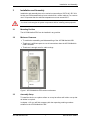
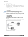
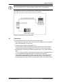
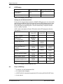
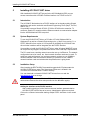
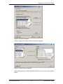
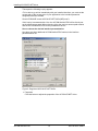
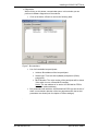
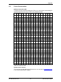
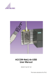
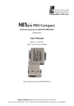
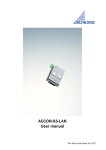
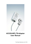
ACCON-NetLink-PRO
User Manual
22-06-07, from FW 1.40
The best solutions for PLC
Copyright
© 1995 - 2007 by
DELTALOGIC Automatisierungstechnik GmbH
Stuttgarter Strasse 3
73525 Schwaebisch Gmuend
Germany
Phone sale:
+49-(0)7171-916-120
Phone support: +49-(0)7171-916-112
Fax sale:
Fax support:
+49-(0)7171-916-220
+49-(0)7171-916-212
E-Mail sale:
[email protected]
E-Mail support: [email protected]
Web site: http://www.deltalogic.de
All rights reserved. No part of this work is allowed to be copied, reproduced,
conferred, processed and stored into electronic media or translated into any other
language without a written permission of the author.
Last update 2007-06-22. All technical changes reserved.
S7-200®, S7-300®, S7-400®, HMI®, STEP® and SIMATIC® are registered trademarks
of Siemens AG, ACCON® and DELTALOGIC® are registered trademarks of
DELTALOGIC Automatisierungstechnik GmbH.
ACCON-NetLink-PRO
2
DELTALOGIC GmbH
Table of Contents
1
Table of Contents
1
Table of Contents............................................................................................. 3
2
Safety Instructions........................................................................................... 5
3
4
5
6
7
8
9
2.1
In General ............................................................................................... 5
2.2
Access Control ........................................................................................ 6
2.3
User Note ................................................................................................ 6
2.4
Appropriate Use ...................................................................................... 6
2.5
Avoid inappropriate Use .......................................................................... 6
Installation and Assembly............................................................................... 7
3.1
Mounting Position.................................................................................... 7
3.2
Minimum Clearance................................................................................. 7
3.3
Assembly Setup ...................................................................................... 7
System Overview ............................................................................................. 8
4.1
Use and Functional Characteristics ......................................................... 8
4.2
Connections ............................................................................................ 9
4.3
LED-Display .......................................................................................... 10
4.4
Scope of Delivery .................................................................................. 10
4.5
Accessory.............................................................................................. 11
4.6
Firmware update ................................................................................... 11
Installing ACCON-S7-NET driver .................................................................. 12
5.1
Introduction ........................................................................................... 12
5.2
System Requirements ........................................................................... 12
5.3
Installation Setup................................................................................... 12
Interface parametrization .............................................................................. 16
6.1
Create station........................................................................................ 16
6.2
Bus settings........................................................................................... 19
6.3
Driver options ........................................................................................ 25
TCP/IP parametrization.................................................................................. 26
7.1
Notices and error messages.................................................................. 26
7.2
Parametrization via a separate configuration tool .................................. 31
7.3
Web interface ........................................................................................ 31
RFC 1006 (S7 TCP/IP) .................................................................................... 39
8.1
Configuration of the RFC1006 option .................................................... 40
8.2
Using RFC1006 with ACCON-AGLink ................................................... 44
8.3
Using RFC1006 with WinCC v 6.0......................................................... 45
Troubleshooting............................................................................................. 48
10 Appendix ........................................................................................................ 51
10.1 Connector Pin Assignment .................................................................... 51
ACCON-NetLink-PRO
3
DELTALOGIC GmbH
Table of Contents
10.2 Technical Data ...................................................................................... 52
10.3 Further Documentation.......................................................................... 53
11 Table of Figures ............................................................................................. 54
12 Table of Charts............................................................................................... 56
13 Index ............................................................................................................... 57
ACCON-NetLink-PRO
4
DELTALOGIC GmbH
Safety Instructions
2
Safety Instructions
Please follow the indicated safety instructions for your own safety and others. They
are showing possible dangers and providing an indication of how to avoid them.
The manual in hand uses the following pictograms:
Hints and further information
Calls attention to dangers and sources of error
A general or specific danger
2.1
In General
The ACCON-NetLink-PRO is intended to be used in a complete system.
In individual cases the operator of a machinery is obligated to follow the safety
regulations and the accident prevention regulation.
When projecting you have to follow the safety regulations and the accident
prevention regulation as the case arises.
According to EN 60204 / IEC 204 emergency stops have to remain active in all
machinery modes. Avoid undefined system restarts.
Errors appearing in the machinery which can cause damage to persons or material
have to be intercepted by additional external mechanisms. In case of an error those
mechanisms e.g. electro-magnetic safety switches, mechanic lockings,etc. (look EN
954-1, risk analysis)have to guarantee for a save operating status.
Do not execute or initiate security relevant functions via an operator terminal.
ACCON-NetLink-PRO
5
DELTALOGIC GmbH
Safety Instructions
2.2
Access Control
As the assemblies are an open operational equipment they have to be installed in
electrical operating areas, cabinets or cases only. It is important that they only can
be entered with a tool or a key by authorized or instructed staff.
Only authorized staff may have access to the assembly!
2.3
User Note
This guide is for planners, operators and mechanics who are using the
ACCON-NetLink-PRO.
This guide shows an operator the handling of the ACCON-NetLink-PRO and
explains signaling functions. It also provides all necessary data for assembling.
The ACCON-NetLink-PRO is intended for the exclusively use with a Siemens
S7-300/S7-400 automation device.
The ACCON-NetLink-PRO is intended to be used in a complete system. For this
reason it is important that planners, users and mechanics are following standards,
safety regulations and accident prevention regulations for the respective case of
operation. The operator of the automation system is obligated to meet the abovementioned regulations.
When projecting you have to follow the safety regulations and the accident
prevention regulation as the case arises.
2.4
Appropriate Use
As already mentioned in the manual use the ACCON-NetLink-PRO as a
communication system only.
2.5
Avoid inappropriate Use
Do not control security related functions via the ACCON-NetLink-PRO only.
Uncontrolled restarts are to be ruled out.!
ACCON-NetLink-PRO
6
DELTALOGIC GmbH
Installation and Assembly
3
Installation and Assembly
Installation and assembly have to be carried out according to VDE 0100 / IEC 364.
As they are IP30 assemblies they have to be build in a control cabinet. For a secure
use it is important that the ambient temperature must not exceed 60 ºC.
You have to de-energize all system components before installing new equipment.
3.1
Mounting Position
The ACCON-NetLink-PRO can be installed in any position.
3.2
Minimum Clearance
• To enable the assembling and disassembling of the ACCON-NetLink-USB
• That there is sufficient space to use all connections when the ACCON-NetLinkUSB is installed
• That there is enough room for cable routings
Figure 1: ACCON-NetLink-PRO minimum clearance
3.3
Assembly Setup
To install the device on a plane surface or on top hat rails a wall holder or a top hat
rail holder is required.
In chapter »4.5« you will find accessory with the respecting ordering numbers
suitable for the ACCON-NetLink-PRO.
ACCON-NetLink-PRO
7
DELTALOGIC GmbH
System Overview
4
System Overview
4.1
Use and Functional Characteristics
The ACCON-NetLink-Pro is a communication adaptor between a TCP/IP net and a
PPI, MPI or Profibus. Up to 7 TCP/IP connections and up to 12 PPI, MPI-/Profibus
connections at the same time are supported. These connections can be configured
independently from each other.
The following points are detected automatically:
• 10 MBit/s or 100 MBit/s
• Bus speed (9,6 KBit/s up to 12 MBit/s)
• Bus parameters
The ACCON-NetLink-PRO can either be sourced by a voltage feed of a bus
interface of an automation system or by an external voltage feed.
A 1.2 m connection lead connects the ACCON-NetLink-PRO to the automated
system. As the connecting plug is actively conducted there are no spur lines which
could interfere the bus.
By the use of drivers it is possible to utilize the ACCON-NetLink-PRO as a
• Programming adaptor
• Communication adaptor
By using the RFC 1006 interface it is possible to use software from third-party
companies. This option can be used with S7-300/400 (look for chapter »8 RFC 1006
(S7 TCP/IP)«).
The ACCON-NetLink-PRO is connected to the PC via a switch or hub. The supplied
patch cable is used to establish a connection via a hub/switch.
Figure 2: Connection via hub or switch
ACCON-NetLink-PRO
8
DELTALOGIC GmbH
System Overview
The communication with S7-200 controllers via RFC 1006 is not supported.
It is possible to use the ACCON-NetLink-PRO directly with a Network Interface Card
(NIC). But you have to use a cross-over cable (not supplied).
Figure 3: Connection via corss-over cable
4.2
Connections
The ACCON-NetLink-PRO has the following connection types:
• RJ45 bushing to connect the device to usual hubs or switches using a standard
patch cable (Straight or Cross-Over).
• Voltage supply bushing for feeding DC 24 V.
This can also be used if the utilized automation system does not have a bus
connection with a sufficient voltage feed. Please look for the correct polarity.
• Bus plug with a PG bushing, selectable terminator and a 1.2 m long connection
lead.
The 1.2 m long connection lead is decoupled by the active bus plug thus there is
no spur line and breakdowns with higher baud rates can be avoided.
It is possible to attach additional users on the PG bushing. When the ACCONNetLink-PRO is attached at the end or at the beginning of a bus segment a
terminator has to be inserted (ON). If not the switch must be in the OFF position.
ACCON-NetLink-PRO
9
DELTALOGIC GmbH
System Overview
4.3
LED-Display
Link LED GREEN
Active LED YELLOW
No connection
to Ethernet
OFF
OFF
Ethernet activity
ON
BLINKING
Table 1: LED Display, RJ45 bushing
Starting the ACCON-NetLink-PRO
During the first seconds after the start the POWER LED lights green, the Active LED
and the Connect LED red. After 5 seconds the Connect LED changes to green. After
that the Power LED is blinking green. After the start activity has finished only the
Power LED lights permanently green. Thus the start activity is complete and the
device is ready to operate.
If RFC 1006 is activated the Power LED and the Active LED light green after the
start activity.
Power LED
Ready to operate
GREEN
Searching for
TCP configuration
BLINKING
GREEN
Active LED
Connect LED
GRÜN
BLINKING
GREEN
Device is logged on the bus
GREEN
GREEN
Active connection to a
controller
GREEN
GREEN
GREEN
Data exchange with a
controller
GREEN
GREEN
BLINKING
GREEN
BLINKING
GREEN
BLINKING RED
BLINKING
RED
Store firmware update
GREEN
RED
RED
Bus-sided exception error
GREEN
PC-sided exception error
GREEN
Trying to log on bus
Transmit firmware update
BLINKING
RED
BLINKING RED
Table 2: LED Display, ACCON-NetLink-PRO
4.4
Scope of Delivery
• A ready for use ACCON-NetLink-PRO
• A 3 m patch cable (Straight)
• A DELTALOGIC Automatisierungstechnik-CD including ACCON-S7-NET driver
• A user manual
ACCON-NetLink-PRO
10
DELTALOGIC GmbH
System Overview
4.5
Accessory
Top hat rail holder Item-No. 13012-HS
The top hat rail holder is required for mounting the ACCON-NetLink-PRO on DIN
rails. No additional tool kits are required to separate the ACCON-NetLink-PRO from
a top hat rail holder. To install the ACCON-NetLink-PRO on plane surfaces it is
possible to channel the top hat rail holder into a wall holder by unscrewing the top
hat rail adaptor.
Plug-in power supply unit 13012-24VDC
Input: AC 100-240 V / 50-60 Hz,
Output: DC 24 V / 330 mA
4.6
Firmware update
To use this manual with an ACCON-NetLink-PRO at least firmware 1.40 is required.
You can find actual drivers and firmware versions on our web site at
www.deltalogic.de in the section Download/ACCON-NetLink or on the supplied
DELTALOGIC Automatisierungstechnik-CD.
ACCON-NetLink-PRO
11
DELTALOGIC GmbH
Installing ACCON-S7-NET driver
5
Installing ACCON-S7-NET driver
With installed ACCON-S7-NET drivers for the ACCON-NetLink-PRO you can
access controllers with a PPI,MPI-/Profibus interface via TCP/IP from a PC.
5.1
Introduction
The ACCON-S7-Net latches into a PG/PC interface of an already existing Simatic
application and can be used with most Simatic Engineering-Tools (Step7, ProTool,
WinCC, etc.).
It is possible to access Simatic S7-200, S7-300 or S7-400 series controller. To
connect a Simatic S7 controller with the Ethernet network a communication adaptor
like the ACCON-NetLink-PRO is required.
5.2
System Requirements
To use the ACCON-S7-NET driver on PG side a PC with Windows 2000 or
Windows XP as well as a Simatic-Engineering tool e.g. Step7 from version 5.1 or
STEP7-Micro/Win from version 4.0 is required. By installing the ACCON-S7-Net
driver further interfaces will be integrated into the PG/PC interface.
It is possible to install the ACCON-S7-NET driver under Windows 98/ME/NT but we
do not provide any support. And please take notice of the used Step7 requirements.
The PCs must have a working network connection set up via Ethernet. The network
configuration has to be known, too. Usual network interface cards can be used. To
achieve a good performance in a local area network you have to use 100Mbit/s
network interface cards and switches. Naturally it is possible to use 10Mbit/s
network interface cards and switches but the performance is going down.
5.3
Installation Setup
After inserting the DELTALOGIC Automatisierungstechnik-CD please start the
ACCON-S7-NET driver setup. The SetupAcconS7Net.exe is located in the
»CD-drive:\ACCON-NetLink\S7-Treiber« directory.
You can download our latest ACCON-S7-NET drivers from our web site
www.deltalogic.de at no charge.
When installing drivers under Windows 2000 or Windows XP you need to log on as
administrator because the driver setup enrolls into the Windows registry.
Adding the interface to the PG/PC interface
After installing the driver for the first time the new interface parameterization
ACCON-S7-NET NLPRO has to be set up. Administrator rights are required.
Click on the »Select« button after starting »adjust PG/PC interface« in the control
panel.
ACCON-NetLink-PRO
12
DELTALOGIC GmbH
Installing ACCON-S7-NET Driver
Figure 4: Set PG/PC Interface
Then the dialog field »Install / Remove Interfaces« appears
Figure 5: Install / Remove Interfaces
After choosing the entry »ACCON-S7-NET NLPRO« on the left click on the »install«
button.
ACCON-NetLink-PRO
13
DELTALOGIC GmbH
Installing ACCON-S7-NET driver
Thereupon the following inquiry appears:
»To be able to go online immediately with your installed interface, you must set the
access path of the access point of your application to the interface parameter
assignment that was created.
Should S7ONLINE access ACCON-S7-NET NLPro(MPI) now?«
If this inquiry is answered with »Yes« the ACCON-NetLink-PRO will be directly set
as the actual access path. When choosing »No« the previous access path remains
and the ACCON-NetLink-PRO will be just added to the list.
How to choose the desired interface parametrization
Now there are three additional ACCON-NetLink-PRO entries in the interface
parametrization list.
Figure 6: Registered ACCON-S7-NET NLPro
• Properties:
Click this button to adjust the properties of the ACCON-S7-NET driver.
ACCON-NetLink-PRO
14
DELTALOGIC GmbH
Installing ACCON-S7-NET Driver
• Diagnostics:
When clicking on this button a new window opens. In this window you can
perform a hardware diagnostics of the modules.
§
Click on the button »Read« to receive the following data:
Figure 7: Bus members
§
§
List of all reachable bus participants
•
Address: Bus address of the bus participant
•
Station type: There are active (Master) and passive (Slave)
participants.
•
MLFB Number: The order number of the participant will be shown
if the switch is set to »Detect MLFB number«
Notice: The own address of an active ACCON-NetLink-PRO is
shown as »station address«.
Bus parameters with which the ACCON-NetLink-PRO logs into the bus. If
there is no automatic detection of the bus parameters then the set bus
parameters are shown (look for chapter »6.2 Bus settings«).
.
ACCON-NetLink-PRO
15
DELTALOGIC GmbH
Interface parametrization
6
Interface parametrization
When choosing the ACCON-NetLink-PRO in the »Adjust PG/PC interface« window
you can specify the access path by the »Properties« button.
The access path’s attributes of the ACCON-NetLink-PRO are split into the following
three parts:
• Local Connection (TCP/IP)
Here you can adjust via which ACCON-NetLink-PRO address the desired
connection to the automation system should be established. Furthermore the
ACCON-NetLink-PRO can be parametrized via this window.
• Bus Settings:
Here you can configure with which bus configuration (e.g. station address, baud
rate) the ACCON-NetLink-PRO is reporting to the bus system.
• Options:
Here you can change the ACCON-S7-Net driver’s language and readout the
driver’s version information.
Figure 8: Settings ACCON-S7-Net
6.1
Create station
To access an ACCON-NetLink-PRO via the ACCON-S7-NET driver you have to
create a station. This station is just virtual and will not be stored in the
ACCON-NetLink-PRO. This is for a better assignment if there are several ACCONNetLink-PROs used.
Via the button »New« you will get to an input dialog. There you have to enter a
reachable IP address of an ACCON-NetLink-PRO and a user-defined name.
ACCON-NetLink-PRO
16
DELTALOGIC GmbH
Interface parametrization
Figure 9: Create station
When using more than one ACCON-NetLink-PRO behind a router, you have to set
the »internet remote maintenance« function for each station. Every station must
have its own port address. Furthermore the router must support NAPT (Network
Address Port Translation) respectively PAT (Port Address Translation) For more
information look for chapter »7 TCP/IP parametrization«.
By clicking »OK« the station will be stored and can be used from now on.
It is more comfortable to search in the local network for already existing ACCONNetLink-PRO. To do this click on the »Search ACCON-NetLink-PRO« button. This
function can be used in a physical network segment only.
Figure 10: Connected ACCON-NetLink-PRO in local network
When chosen the desired ACCON-NetLink-PRO click on the button »Close + Get«.
Then the following dialog appears again:
ACCON-NetLink-PRO
17
DELTALOGIC GmbH
Interface parametrization
Figure 11: Station
This can be saved by the »OK« and is from now on available.
If you want another name as the one stored in the ACCON-NetLink-PRO you can
delete it (instead of »MyName« you can choose e.g. »Thomas«).
Figure 12: Properties, local connection
The driver-sided settings are complete now.
It may be possible that the ACCON-NetLink-PRO must be adjusted to the conditions
of the network.
It is possible to configure the ACCON-NetLink-PRO via the web interface (look for
chapter »7.3«) or the tool »NETLink PRO Konfiguration« (look for chapter »7.2«).
ACCON-NetLink-PRO
18
DELTALOGIC GmbH
Interface parametrization
6.2
Bus settings
The ACCON-NetLink-PRO can be used with three different bus systems, PPI, MPI
and Profibus.
From a user's view the bus systems only differ in the selectable transfer rates. As
well as in the additional options for Profibus.
The ACCON-NetLink-PRO can be used without indicating bus-specific information.
Through the autobaud function the ACCON-NetLink-PRO determines the bus
parameters independently. This enables that the ACCON-NetLink-PRO can be used
with different automation systems with different transfer rates. You can do this
without switching the ACCON-S7-NET driver.
This autobaud function is only supported when in the participating automation
system the function »Cyclic distribution of the bus parameters« is enabled.
There are older Siemens PLCs which do not support the autobaud function on MPI.
This function is not available for S7-200 systems.
If you want another name as the one stored in the ACCON-NetLink-PRO you can
delete it (instead of »MyName« you can choose e.g. »Thomas«).
MPI Configuration
The station address is the most important setting in connection with the bus
configuration. It is the address which should the ACCON-NetLink-PRO have when
going online. The station address' value can be in the range of »0« to »126« if the
chosen address is less or equal the highest node address (HSA).
Example: HSA = 31
For the station address you can indicate any value in the range of »0« to »31«
unless this address does not already exist on the bus.
You can parametrize the timeout of the ACCON-S7-NET driver in the station-related
settings. If there is no response to a driver request within the set timeout a
communication error will be sent to the Simatic application. When shortening the
timeout you will neither get a reduction of the transmission time nor an increase of
the data throughput, etc. .
You have to adjust the transfer rate as well as the HSA of the automation system to
be communicated with in the network-related settings.
ACCON-NetLink-PRO
19
DELTALOGIC GmbH
Interface parametrization
Figure 13: Autobaud function activated, MPI
To ease the configuration you can use the function »Automatic reconnaissance of
the net-related parameters«. Because of this the initialization of a connection lasts a
bit longer as online parameters have to be determined.
»Automatic reconnaissance of the net-related parameters« (autobaud function) can
not be used when in the utilized PLC the function »Cyclical bus parameter
spreading« is not activated or supported, e.g.
- S7-200
- Older Siemens S7 PLCs
- ACCON-NetLink-PRO is the only master on the bus
It is possible that the autobaud function does not work reliably when using a slower
transfer rate (e.g. 19,2 Kbit/s) or with global data communication.
Profibus configuration
In principle it is the same as with the MPI configuration. But you have to remember
that the net-related parameters are more voluminous.
With Profibus you have the additional parameter fields »bus profile« and »bus
parameters«.
ACCON-NetLink-PRO
20
DELTALOGIC GmbH
Interface parametrization
Figure 14: Autobaud function deactivated, Profibus
Profile:
Generally, in Profibus there are the profiles »DP«, »Standard« and »User-defined«.
You have to choose the profile which is used in the automation system.
Bus parameters:
Unlike the MPI bus profile the bus parameters with Profibus are not constant and
change with the type and number of the used Profibus participants.
You should always set the Profibus parameters which are used in the automation
system.
Figure 15: Bus parameters
To avoid these partly complex steps it is advantageous to use the autobaud
function. This function determines the bus parameters automatically.
ACCON-NetLink-PRO
21
DELTALOGIC GmbH
Interface parametrization
Figure 16: Autobaud function activated, Profibus
»Automatic reconnaissance of the net-related parameters« (autobaud function) can
not be used when in the utilized PLC the function »Cyclical bus parameter
spreading« is not activated or supported, e.g.
- S7-200
- Older Siemens S7 PLCs
- ACCON-NetLink-PRO is the only master on the bus
ACCON-NetLink-PRO
22
DELTALOGIC GmbH
Interface parametrization
The following screenshot shows the switch for the »cyclic distribution of the bus
parameters«. The switch is located in the hardware configuration of any Profibus
interface.
Figure 17: Profibus, bus parameters
PPI configuration
The station address is the most important setting in connection with the bus
configuration. It is the address which the ACCON-NetLink-PRO has when going
online. The station address' value can be in the range of »0« to »126« if the chosen
address is less or equal the highest node address (HSA). The address must not be
on the bus.
The timeout value shows how long the communication drivers should try to establish
a communication.
Using network-related settings the transfer rate and the highest node address have
to meet that of the automation system which is responded to.
Normally, the baud rate cannot be determined on PPI busses, automatically!
ACCON-NetLink-PRO
23
DELTALOGIC GmbH
Interface parametrization
Figure 18: »Use bus parameters from ACCON-NetLink S7« deactivated
For further information about Advanced PPI please look for the manual of your
S7-200 programming software.
The automatic detection of net-related parameters is not possible with S7-200
controls.
You have to activate Advanced PPI when communicating with an EM 277.
The PPI communication is supported from version 2.5 of the ACCON-S7-NET
driver. You need at least firmware version 1.40.
You will find actual drivers and firmwares on our web site at www.deltalogic.de in the
section download/ACCON-NetLink.
ACCON-NetLink-PRO
24
DELTALOGIC GmbH
Interface parametrization
6.3
Driver options
You can change the language of the driver's output and help texts in the options of
the ACCON-S7-NET driver. And the versions of the used driver data can be read
out, too.
Figure 19: Language settings
Switching the language
You can choose between German and English.
After you have switched languages call the settings window again to accept the
changes.
Versions
The names and versions of all driver data are indicated here.
If problems occur you can quickly check if the correct versions are installed by
indicating the driver data.
You will find actual drivers and firmwares on our web site at www.deltalogic.de in the
section download/ACCON-NetLink.
ACCON-NetLink-PRO
25
DELTALOGIC GmbH
TCP/IP parametrization
7
TCP/IP parametrization
There are three ways to make the TCP/IP parametrization in the ACCON-NetLinkPRO.
• Parametrization via »Set PG/PC Interface«
• Parametrization via the tool »NETLink PRO Konfiguration«
(look for chapter »7.2«)
• Parametrization via the web interface of the ACCON-NetLink-PRO
(look for chapter »7.3«)
The ACCON-NetLink-PRO has the IP address 192.168.4.49 in the condition as
supplied to the customer.
7.1
Notices and error messages
When configuring the ACCON-NetLink-PRO via the ACCON-S7-NET driver you
have to remember the following things:
• If the ACCON-NetLink is active on the bus at the same time as the desired
parametrization (e.g. if a module or a variable table is being watched) no change
will be made. The following message appears:
»The ACCON-NetLink-PRO cannot be parametrized now.«
• Via a password the ACCON-NetLink-PRO can be protected against
unauthorized parametrization. If you want to parametrize it using an invalid
password you will receive the following message:
»Wrong Password«
The used standard values before firmware 1.40
User name: ACCON-NetLink-PRO
Password: (empty)
The used standard values from firmware 1.40
User name: ACCON-NetLink-PRO
Password: admin
• The message »ACCON-NetLink-PRO parameters written successfully « appears
when the password and the parametrization period are kept in mind during the
parametrization.
ACCON-NetLink-PRO
26
DELTALOGIC GmbH
TCP/IP parametrization
The reboot period depends on the DHCP (Dynamic Host Configuration Protocol)
timeout. This period may take approximately 20 seconds plus the adjusted DHCP
timeout.
Setting TCP/IP parameters
To change the TCP/IP parameters just choose the desired station and call it via the
»Change« button.
Figure 20: Chosen station
Via the button »Parametrize ACCON-NetLink-PRO...« you will get to an input mask
which is filled with read out parameters of the ACCON-NetLink-PRO.
Figure 21: Settings ACCON-NetLink-PRO
ACCON-NetLink-PRO
27
DELTALOGIC GmbH
TCP/IP parametrization
If there is no ACCON-NetLink-PRO reachable by using the station's indicated
IP address the following message appears:
Figure 22: ACCON-NetLink-Pro does not respond
Two possible reasons:
• There is no ACCON-NetLink-PRO in connection with the indicated IP address
(e.g. the device is off-state or still booting).
• The IP configuration of the used PC does not match the IP configuration of the
indicated ACCON-NetLink-PRO (e.g. different network addresses).
As you can see in the parametrization mask it is possible to assign IP parameters
via DHCP (Dynamic Host Configuration Protocol) next to the static IP address
assignment.
Static TCP/IP-Configuration
If the ACCON-NetLink-PRO is used in a network without a DHCP server or the
device shall be used in a DHCP server but is designated to operate with a static IP
address you have to enter the desired IP parameters in the »Static Parameters«
input masks.
In this case do not tick the »Assign IP addresses automatically (DHCP)« function.
When selecting »Save in ACCON-NetLink-PRO« the parameters are saved in the
ACCON-NetLink-PRO.
Using DHCP
DHCP has the problem that after each switch-on the DHCP server is assigning
another IP address to the parametrized ACCON-NetLink-PRO.
The DHCP system administrator can take measures against this when doing the
following: He has to assign a fix IP-address to the ACCON-NetLink-PRO's MAC
address on the DHCP server. This requires additional work for the system
administrator.
If the ACCON-NetLink-PRO should receive its IP parameters automatically via the
DHCP server you have to activate the »Assign IP addresses automatically (DHCP)«
function.
In addition the »DHCP Timeout in S« function is enabled. Does the ACCONNetLink-PRO not receive parameters from a DHCP server within the time set it will
use static parameters. This secures that the device is reachable an re-configurable.
As most of the DHCP servers need 12 to 20 seconds to assign valid parameters,
inputs lesser than 30 seconds will be replaced by a standard value of 30 seconds.
By clicking on the »Store in NetLink-Pro« button the parameters will be stored in the
ACCON-NetLink-PRO.
ACCON-NetLink-PRO
28
DELTALOGIC GmbH
TCP/IP parametrization
Additional Features
When choosing the »ACCON-NetLink-PRO Properties« button you are in the
»ACCON-NetLink-PRO Settings« with the following options:
• Name:
Here you can give the ACCON-NetLink-PRO a proper name which eases its
identification in the searching window. This name is stored in the device.
It is advantageous to name the devices in connection to its site
(e.g. conveyor HG1), users (e.g. John Q. Public) or miscellaneous.
• Change Password:
Here you can set a new password or change an already existing one.
When using a password you can only change the ACCON-NetLink-PRO's
configuration with it. Parametrization via drivers and web interface is protected
by this password.
The used standard values before firmware 1.40
User name: ACCON-NetLink-PRO
Password: (empty)
The used standard values from firmware 1.40
User name: ACCON-NetLink-PRO
Password: admin
Figure 23: Change password
• Active Web Interface
If activated you can watch the ACCON-NetLink-PRO's parametrization via all
standard browsers e.g Internet Explorer, Opera, Mozilla Firefox and as the case
may be change it. But the respective password is required.
For more information about the web interface please look for chapter »7.3«.
To store parameters in the ACCON-NetLink-PRO click on »Store in NetLink-Pro«
button.
Using the ACCON-NetLink-PRO for Remote Maintenance
When using the ACCON-NetLink-PRO for remote maintenance the network
administrators of both locations have to be consulted.
There are different ways to realize a remote maintenance via a WAN (Wide Area
Network). Here are a few suggestions:
ACCON-NetLink-PRO
29
DELTALOGIC GmbH
TCP/IP parametrization
Assigning an own and public IP address
which is directly connected to the net:
Advantages
Disadvantages
-realized very fast
-only a few addresses world-wide
available
-Administrator does note have to engage -additional network with a direct WAN is
required
-not secure
Utilization behind a router using NAT:
Advantages
Disadvantages
-integrable into an already existing
infrastructure
-network administrators have to
parametrize routers and firewalls
between the involved communication
partners
-not visible/usable for everyone when the
administrator is taking measures
Figure 24: More than one ACCON-NetLink-PRO behind a router
When using more than one ACCON-NetLink-PRO behind a router you have to mark
the function »Internet teleservice« and to every station there must be a port address
assigned to. Furthermore the router must support NAPT (Network Address and Port
Address Translation) respectively PAT (Port Address Translation).
ACCON-NetLink-PRO
30
DELTALOGIC GmbH
TCP/IP parametrization
Using a dial-up router (ISDN):
Advantages
Disadvantages
-easy to realize if a telephone extension
is available
-telephone charges causing additional
costs
-loose of performance due to low
bandwidth
A little help when using TCP/IP
Basic problems when using TCP/IP and the most frequent sources of error are
discussed in chapter »9 Troubleshooting«.
7.2
Parametrization via a separate configuration tool
If there is no Siemens PG/PC interface on the parametrization PC you can
parametrize the ACCON-NetLink-PRO via the integrated web interface
(chapter »7.3«) or the separate configuration tool.
After the installation of the ACCON-S7-NET driver you can start the tool via
»Start/Programs/DELTALOGIC/NETLink-S7-NET/NETLink PRO Konfiguration«.
After starting the program the network will be searched for ACCON-NetLink-PROs.
The result is shown in the following window:
Figure 25: »NETLink PRO Konfiguration«
When choosing any ACCON-NetLink-PRO from the list you can parametrize it by
clicking on »Parametrieren« (parametrize). It is the same way as described in
chapter »7.1«.
The ACCON-NetLink-PRO has the IP address 192.168.4.49 in the condition as
supplied to customer.
7.3
Web interface
If not deactivated by the user the web interface of the ACCON-NetLink-PRO can be
opened with every standard browser (e.g. Internet Explorer, Mozilla Firefox, Opera,
etc.). The web interface should provide the user with information and support him
when doing configuration tasks.
ACCON-NetLink-PRO
31
DELTALOGIC GmbH
TCP/IP parametrization
Welcome page
You can call the ACCON-NetLink-PRO's welcome page when entering »http://<ipaddress».
The used standard values before firmware 1.40
User name: ACCON-NetLink-PRO
Password: (empty)
The used standard values from firmware 1.40
User name: ACCON-NetLink-PRO
Password: admin
Figure 26: Web interface of the ACCON-NetLink-PRO
From this site you get to the status site, configuration site and to the web site of the
DELTALOGIC Automatisierungstechnik GmbH.
Status site
From the status site reachable via a link on the welcome page you gain information
about the ACCON-NetLink-PRO but you cannot reconfigure it.
ACCON-NetLink-PRO
32
DELTALOGIC GmbH
TCP/IP parametrization
Figure 27: ACCON-NetLink-PRO status
ACCON-NetLink-PRO
33
DELTALOGIC GmbH
TCP/IP parametrization
This site provides general (e.g. firmware version, number of possible connections,
etc.) as well as special (baud rate, active participants, DHCP status, etc.)
information which eases the search for errors.
Device-specific parameters:
Product name
ACCON-NetLink-PRO
Firmware name
ACCON-NetLink-PRO
Firmware version
e.g. V1.00
Serial number
e.g. T00000062
MAC address
e.g. 00:06:71:19:00:3E
Bus-specific parameters:
Station address
When the ACCON-NetLink-PRO is active on the bus, the own
station address is indicated.
Bus parameters
When the ACCON-NetLink-PRO is active on the bus, the bus
parameter set is shown broken down.
Max. possible bus
connections
Number of highest possible and simultaneous bus connections
(at the moment 12).
List of active
stations
When the ACCON-NetLink-PRO is active on the bus a list of
the active stations is output. The own address is marked red.
Sum of used bus
connections
When the ACCON-NetLink-PRO has opened at least one bus
connection then the number of open connections is shown
here.
TCP/IP-specific parameters:
IP address
The actual IP address of the ACCON-NetLink-PRO is
shown (e.g. 192.168.4.54).
Subnet mask
The actual subnet mask of the ACCON-NetLink-PRO
is shown (e.g. 255.255.255.0).
Gateway
The actual standard gateway of the ACCON-NetLinkPRO is shown (e.g. 192.168.4.33).
DHCP status
Shows if DHCP is activated or not.
If on it shows if DHCP was successful or if the
parametrized default IP address is used..
Device Name
If so the free-selectable name of the ACCONNetLink-PRO is shown.
Max. possible bus
connections
Number of the maximum possible and simultaneous
IP connections (at the moment 7).
Communication port
Port number of the TCP/IP communication port
(standard 7777)
Sum of used
TCP connections
The number of open TCP connections is shown if the
ACCON-NetLink-PRO has at least one open RFC or
TCP connection.
ACCON-NetLink-PRO
34
DELTALOGIC GmbH
TCP/IP parametrization
Configuration site
From the configuration site reachable via a link on the welcome page you can
configure the ACCON-NetLink-PRO. Before you can open this site you have to enter
the correct device name (ACCON-NetLink-PRO) and the password.
Figure 28: Name and password
Take notice of case sensitivity.
The used standard values before firmware 1.40
User name: ACCON-NetLink-PRO
Password: (empty)
The used standard values from firmware 1.40
User name: ACCON-NetLink-PRO
Password: admin
ACCON-NetLink-PRO
35
DELTALOGIC GmbH
TCP/IP parametrization
Figure 29: ACCON-NetLink-PRO configuration
ACCON-NetLink-PRO
36
DELTALOGIC GmbH
TCP/IP parametrization
If entered all data successfully you can access all parameters. They are not
write-protected and configurable via the ACCON-S7-Net's driver interface.
Static IP address
Used when DHCP is switched-off or DHCP timeout
expires.
Static Subnet Mask
Used when DHCP is switched-off or DHCP timeout
expires.
Static Gateway
Used when DHCP is switched-off or DHCP timeout
expires
Device Name
Alpha-numeric name with a maximum length of 20.
DHCP Status
ON or OFF
DHCP Timeout
30 to 65500 Seconds
Web Status
Web Interface ON or OFF
New Password
Password with a eight-digit maximum
Retype new Password
Retype Password with a eight-digit maximum
Table 3: ACCON-NetLink-PRO parameters
RFC 1006 specific parameters
RFC 1006 status
Shows if RFC 1006 has been activated or
not (ON or OFF).
When activated (ON) further parameters
are visible.
Bus autobaud ON/OFF
Shows if the bus parameters of the bus
system should be detected automatically
(ON). Or if the stored bus parameters
should be used to go online (OFF).
Own station address
Indicates the own station address. The
ACCON-NetLink-PRO uses this address to
participate on the bus cycle.
Stored bus parameters
If autobaud is OFF the stored bus
parameters are shown here. The ACCONNetLink-PRO uses these to go online when
RFC 1006 is activated.
Rack/Slot mode
Shows if the R/S-Mode (ON) or the
Addressed-Mode (OFF) is used.
Fixed target address for R/S mode
If R/S mode is activated all incoming RFC
1006 requests are forwarded to the here
parametrized bus address.
Max. possible IP connections (RFC)
Number of maximum possible and
simultaneous IP connections for the RFC
1006 communication.
Sum of the used RFC connections
The number of open RFC connections is
shown here when the ACCON-NetLinkPRO has opened at least one TCP or
RFC1006 connection.
Table 4: RFC 1006 specific parameters
ACCON-NetLink-PRO
37
DELTALOGIC GmbH
TCP/IP parametrization
You can undo the already made changes by clicking the »Cancel« button.
When clicking on the »OK« button the entries are tested for correctness. If
necessary a false entry with an appropriate solution is shown.
If all entries are correct the changes which will be stored in the ACCON-NetLinkPRO are shown.
After saving new parameters the ACCON-NetLink-PRO restarts to activate the new
configuration.
If desired the ACCON-NetLink-PRO can be restarted remotely. Just click on
»System Reset«.
The restart period depends on the DHCP (Dynamic Host Control Protocol) timeout.
But it takes at least 20 seconds plus the adjusted DHCP timeout.
Security site
The security site is reachable via the link »ACCON-NetLink-PRO Security«. From
this site rudimental TCP security settings can be carried out. But before you can
open this site you have to enter the correct device name (ACCON-NetLink-PRO)
and the password (standard password »admin«). Via the button »factory defaults«
you can reset the ACCON-NetLink-PRO.
The used standard values before firmware 1.40
User name: ACCON-NetLink-PRO
Password: (empty)
The used standard values from firmware 1.40
User name: ACCON-NetLink-PRO
Password: admin
ACCON-NetLink-PRO
38
DELTALOGIC GmbH
RFC 1006 (S7 TCP/ IP)
8
RFC 1006 (S7 TCP/IP)
As an additional function the ACCON-NetLink-PRO has implemented the RFC
1006-Protocol (also known as S7-TCP/IP or as ISO on top of TCP). This function
can be activated via the ACCON-NetLink-PRO's web interface.
As many visualization system manufacturers have implemented this protocol to
realize a connection to Simatic controllers via Ethernet-CPs from Siemens (e.g.
CP343 or CP443), the ACCON-NetLink-PRO with RFC1006 is a low-cost alternative
to communicate with these visualization systems.
Figure 30: RFC 1006 options
The following software packages incl. RFC 1006 support have been tested in
conjunction with the ACCON-NetLink-PRO:
• WinCC V6.0 (Siemens AG)
• ZenOn V6.2 (COPA-DATA)
• PROCON-Win V3.2 (GTI Control)
• S7-OPC-Server V3.1 and higher (Systeme Helmholz GmbH)
• AGLink V4.0 (DELTALOGIC Automatisierungstechnik GmbH)
• INAT-OPC-Server (INAT GmbH)
• WinCE 5.0 Terminal TP21AS (Sütron Electronic GmbH)
The communication with S7-200 controllers via RFC 1006 is not supported.
ACCON-NetLink-PRO
39
DELTALOGIC GmbH
RFC 1006 (S7 TCP/ IP)
8.1
Configuration of the RFC1006 option
RFC1006 is configured via the web interface. When activated you have to
parametrize the following options.
After saving the configuration and restarting the ACCON-NetLink-PRO, the settings
are shown clearly on the status site of the web interface.
Autobaud
By using the option »Bus autobaud ON/OFF« you can preset if the ACCON-NetLinkPRO is searching for bus parameters when logging on the bus. Then you can
choose if the NetLink should go online with the found or the stored bus parameters.
Possible inputs are »ON« or »OFF«.
Own station address
The »own station address« option indicates the bus address with which the
ACCON-NetLink-PRO will log on to the bus.
The value for the station address must have any value in the range of »0« to »126«
The only precondition is, that the selected address is not larger than the HSA
(highest station address) and is not already being used for another device on the
same bus.
Store specified bus parameters
If the »Bus autobaud ON/OFF« option has been deactivated (OFF), the parameter
fields of the sub item »Stored bus parameters« must be configured carefully.
When parametrizing, please note that all parameters for Profibus are
interdependent. That is, if a parameter, e.g. the baud rate, is changed, all the other
parameters usually also change.
For MPI, on the other hand, all parameters besides the baud rate are fix. This
means that if an MPI connection increases from e.g. 187.5 kBit/s to 12000 kBit/s, all
other parameters remain unchanged.
The following parameters must be taken into account:
• Baud Rate:
The required baud rate is entered in Kbps. E.g. »187.5« or »12000«. The
possible values are: 9,6; 19,2; 45,45; 93,75; 187,5; 500; 1500; 3000; 6000 and
12000.
• HSA
The highest station address is entered here. For MPI generally »31« and for
Profibus »126«. However you do not have to use the standard values.
• TSlot_Init
This value is always »415« for MPI – regardless of which baud rate. For Profibus
the appropriate value should be read from the Profibus project.
• Ttr
This value is always »9984« for MPI – regardless of which baud rate. For
Profibus the appropriate value should be read from the Profibus project.
• Max. Tsdr
This value is always »400« for MPI – regardless of which baud rate. For Profibus
the appropriate value should be read from the Profibus project.
• Min. Tsdr
This value is always »20« for MPI – regardless of which baud rate. For Profibus
the appropriate value should be read from the Profibus project.
ACCON-NetLink-PRO
40
DELTALOGIC GmbH
RFC 1006 (S7 TCP/ IP)
• Tset
This value is always »12« for MPI – regardless of which baud rate. For Profibus
the appropriate value should be read from the Profibus project.
• Tqui
This value is always »0« for MPI – regardless of which baud rate. For Profibus
the appropriate value should be read from the Profibus project.
• Gap
This value is always »5« for MPI – regardless of which baud rate. For Profibus
the appropriate value should be read from the Profibus project.
• Retry
This value is always »2« for MPI – regardless of which baud rate. For Profibus
the appropriate value should be read from the Profibus project.
Please note that under unfavourable circumstances an incorrectly parametrized
ACCON-NetLink-PRO can interfere the bus to the extent that a regular bus
operation is no longer possible.
For this reason, the autobaud function is provided to ensure that the correct
parameters are used. But the PLC must support this function!
Wrong bus parameters can interfere the bus, considerably!
Addressing
RFC1006 connections are virtual point-to-point connections, that means,
connections from the PC to the programmable controller (possible branching within
the programmable controller is managed by the PLC => Routing).
Because the ACCON NetLink-PRO is a point-to-multipoint communications adaptor
(»PC to ACCON NetLink-PRO« on the one hand and »ACCON NetLink-PRO to
many bus stations« on the other), it was necessary to implement different
addressing methods to permit all communication variations. You have to differ
between two addressing methods.
ACCON-NetLink-PRO
41
DELTALOGIC GmbH
RFC 1006 (S7 TCP/ IP)
Addressed Mode
Figure 31: Addressed mode
The addressed mode is suitable if different PLCs are to be accessed on the same
MPI/Profibus via RFC1006.
If this mode is used, the following setting must be parametrized on the configuration
page of the web interface:
• »Rack/slot mode« must be deactivated (OFF), then the Addressed Mode
is active
Now the destination address has to be entered in the RFC1006 driver of the
Windows application (e.g. WinCC, see Section 7.2.1) instead of the rack and slot. In
chapter »8.2« and »8.3« you will find examples for ACCON-AGLink and WinCC.
Please note that the rack and slot together fill only one byte which is divided as
follows:
• Rack fills the upper three bits (11100000 bin for Rack 7, Slot 0)
• Slot fills the lower five bits (00011111 bin for Rack 0, Slot 31)
If you now want to communicate with destination address 2, the following has to be
entered:
Rack 0, Slot 2.
If you want to communicate with destination address 49 the following has to be set:
Rack 1, Slot 17.
You will find in chapter »10.3« a table where you can gather the already converted
values for rack and slot from.
There are also parametrization tools that do not provide fields with names like rack
and slot. These tools normally have a parametrization field with a name such as
Remote TSAP that is usually two bytes long and in hex format. This field, in which
only the lower byte is of interest, is parametrized as follows:
ACCON-NetLink-PRO
42
DELTALOGIC GmbH
RFC 1006 (S7 TCP/ IP)
If you want to communicate with destination address 2, the following has to be
entered:
Remote TSAP 0202hex.
If you want to communicate with destination address 49 the following has to be set:
Remote TSAP 0231hex.
You will find in chapter »10.3« a table where you can gather the already converted
values for rack and slot from.
You can use the formula »Rack * 32 + Slot = Address«.
In chapter »7.2« the addresses mode is explained with the help of a WinCC
example.
Rack/Slot Mode
Figure 32: Rack/Slot mode
In rack/slot mode, it is possible to access several PLCs which are on the same rack
via a bus address.
This is achieved by just communicating directly with one pre-parametrized station.
This station routes the data packets not intended for it to the required rack/slot.
This makes it possible, for example, to communicate in S7-400 systems with more
than one PLC on a rack (Multicomputing) without having to attach further PLCs to
the bus.
To use this function, it is necessary to parameterize the following on the
configuration page of the web interface:
• »Rack/slot mode« must be enabled (ON)
• For »Fix destination address for R/S mode«, the address of the required
communication partner must be entered.
ACCON-NetLink-PRO
43
DELTALOGIC GmbH
RFC 1006 (S7 TCP/ IP)
8.2
Using RFC1006 with ACCON-AGLink
Figure 33: RFC 1006 with ACCON-AGLink
Using the addressed mode it is possible to access several PLCs which are on the
MPI-/ Profibus bus.
Figure 34: AGLink 4.0 configuration
ACCON-NetLink-PRO
44
DELTALOGIC GmbH
RFC 1006 (S7 TCP/ IP)
This configuration can be used for the following software packages:
• ACCON AGLink Version 3.x und 4.0
• DELTALOGIC S7/S5 OPC-Server
• SPS-Analyzer Autospy
• ACCON-S7-Power Tools
• ACCON-S7-EasyLog
8.3
Using RFC1006 with WinCC v 6.0
The basic parametrization of RFC1006 connections in visualization systems is
explained here. E.g. using WinCC V6.0 of the Siemens AG.
To parametrize a RFC 1006 connection in WinCC you have to create a new TCP/IP
connection in the »SIMATIC S7 PROTOCOL SUITE«. This connection is called
»NetLink_PRO«.
Figure 35: RFC 1006 with WinCC v 6.0
By clicking on »settings« you will get to a mask where you have to enter the IP
address of the ACCON-NetLink-PRO as well as the Rack/Slot address of the target.
In this case the ACCON-NetLink-PRO has the IP address 192.168.4.38. The target
PLC with which should be communicated has the Profibus address 49. The
addressed mode is used so you can take the values for Rack and Slot from the
address conversion table in chapter »10.3«.
ACCON-NetLink-PRO
45
DELTALOGIC GmbH
RFC 1006 (S7 TCP/ IP)
Figure 36: TCP/IP connection parameters
If you are using several PLCs in one Rack (Multicomputing) you can access every
single PLC. Therefore you must use the Rack/Slot mode (look for chapter Rack/Slot
mode). You have to indicate the corresponding rack and slot number for the
respecting PLC.
This recently configured connection must get a variable. This is done by a right click
to open the context menu of the new connection and selecting »New variable…«.
Figure 37: Variable properties
In the properties window of the variable, which was named
»MB0_over_NETLink_PRO«, we can now select the type of variable by clicking on
the »Select« button.
Flagbyte 0 is configured here.
ACCON-NetLink-PRO
46
DELTALOGIC GmbH
RFC 1006 (S7 TCP/ IP)
Figure 38: Flagbyte 0 configured
The following screenshot shows that »NETLink_PRO« connection has now a
variable named »MB0_over_NETLink_PRO«.
Figure 39: Connection »NetLink_PRO«
If this variable is now included in the initial screen of the WinCC project, for
example, a connection will be established to the PLC with address 49 via the
ACCON NetLink-PRO to read or write flagbyte 0 from this address.
Of course, further variables of different types can be created and used according to
the same scheme.
It is also possible to create additional TCP/IP connections in order to communicate
not only with the PLC with bus address 49 but also with other PLCs.
ACCON-NetLink-PRO
47
DELTALOGIC GmbH
Troubleshooting
9
Troubleshooting
Q: I do not know my PC's IP address.
A: Use the prompt and enter the command »ipconfig« to gain information about your
Ethernet interface.
Figure 40: ipconfig
Q: My PC has a firewall which ports do I have to release?
A: The ACCON-S7-Net driver communicates with the ACCON-NetLink-PRO via
TCP/IP port 7777. The UDP ports 25342 and 25343 are used when searching for
ACCON-NetLink-PRO devices. To have the ACCON-S7-Net driver's basic
functions please release at least port 7777.
Q: The configuration tool as well as the web interface asks for a password. But I did
not enter one.
A: From firmware version 1.40 the ACCON-NetLink-PRO must have a password. If
no password is set, the standard password is »admin«.
Q: There are no dialog settings in the Simatic Manager.
A: When you installed the ACCON-S7-NET driver for the first time you have to add it
to the PG/PC interfaces, too.
Make sure that you have administrator rights when installing the driver. After an
successful installation you have to reboot your system.
Look for chapter »5.3« page 12-14. Simatic Manager Version 5.1 is minimum!
Q: It is not possible to go online when the adaptor is put on the Profibus
A: If possible use the autobaud function.
If not desired or possible you have to check the Profibus’ timing parameters in
the STEP7 project planning. Via the »Bus Parameters« button you can enlist the
read off values into the extended bus parameter settings. If you still cannot go
online you have to increase the »TRT« (Target Rotation Time) parameter in the
ACCON-NetLink-PRO as well as on the PLC. Look for chapter »8.3« page 40/41.
Q: The program Starter experiences difficulties when accessing a Micromaster
drive.
A: Increase breakdown monitoring to 200 ms and application monitoring to 5000 ms.
ACCON-NetLink-PRO
48
DELTALOGIC GmbH
Troubleshooting
Q: Every time I am executing a certain function it fails and the red Active-LED is
blinking.
A: An exception error in the communication between your PC and the ACCONNetLink-PRO has occurred. Please contact our support and tell them how to
trigger this error. We will try to solve the problem as soon as possible.
Q: Every time I am executing a certain function it fails and the red Connect-LED is
blinking.
A: An exceptional error in the communication between the ACCON-NetLink-PRO
and the automation system has occurred. Please contact our support and tell
them how to trigger this error. We will try to solve the problem as soon as
possible.
Q: Sometimes MPI or Profibus connections with high baud rates are getting
disconnected although the ACCON-NetLink-PRO is put on the PLC and no other
users are connected.
A: Be sure that the bus is correctly terminated.
Even though the ACCON-NetLink-PRO is the only device connected to the bus in
addition to the PLC. You have to insert the final resistor. Above all high baud
rates can be interfered.
Q: If I set the ACCON-NetLink-PRO to autobaud in the PG/PC interface and try to
go online, the active LED lights up briefly before a message appears telling me
that the bus parameters cannot be determined.
A: Please deactivate the autobaud functionality in the NETLink-S7-NET driver
(PG/PC interface) and set the correct baud rate and the correct profile.
Q: In the web interface, I enabled the RFC functionality and would like the ACCONNetLink-PRO to go onto the bus using autobaud.
Unfortunately, the active LED just flashes but no communication is possible via
my visualization system.
A: Please deactivate the autobaud functionality in the web interface of the ACCONNetLink-PRO and set the correct baud rate with the corresponding bus
parameters.
Q: I have read that the ACCON-NetLink-PRO can communicate with up to seven
PCs at the same time. But I can’t manage to query a status of my automation
system from more than six PCs at once.
A: A total of seven TCP connections are available that can be used at the same
time. However, please note that only up to six connections can be used at once
per type of connection (NETLink-S7-NET or RFC1006 connections are possible).
The purpose of this is to keep one connection channel free for the other protocol.
Q: I am using the rack/slot mode of the RFC1006 interface and have specified
address 2 for my existing PLC in the web interface in »Fix destination address for
R/S mode«.
Although ACCON-NetLink-PRO online is active (active LED lights up), my
visualization system tells me that no connection can be established.
A: Make sure you have assigned the correct values to rack and slot in the
parametrization. Look for chapter »8.1« page 43.
ACCON-NetLink-PRO
49
DELTALOGIC GmbH
Troubleshooting
Q: I would like to use addressed mode of the RFC1006 interface (rack/slot mode =
OFF) because of that way I can access several PLCs on the same bus.
Unfortunately, I am not sure how to parameterize the fields rack and slot in the
visualization used.
A: If addressed mode is used, a combination of rack and slot specifies the
destination address of the automation system. Look for chapter »8.1« page 42.
Q: If I mix RFC1006 connections and connections via the STEP7 driver, the
connection sometimes breaks off or error messages appear saying that it is not
possible to establish a connection.
A: For communication with S7-300 modules it may be necessary to parameterize
the communication resources.
The user can influence the allocation of existing »Connection Resources« under
object properties of the PLC in the hardware configuration.
Q: Once the configured Profibus slaves have been added on my PLC,
communication between ACCON-NetLink-PRO and STEP7 becomes markedly
slower.
A: The user can influence the allocation of »Scan Cycle Load from Communication
[%]« under object properties of the PLC in the hardware configuration. The
default value is 20 %.
ACCON-NetLink-PRO
50
DELTALOGIC GmbH
Appendix
10
Appendix
10.1
Connector Pin Assignment
MPI/Profibus Interface Assignment
Connection
Signal
Meaning
1
-
unused
2
GND
Mass (looped through)
3
RxD / TxD-P
Received Data-P /
Transmission Data-P
4
-
unused
5
DGND
Mass for bus scheduling
(looped through)
6
DVCC
DC 5 V for bus scheduling
(looped through)
7
VCC
DC 24 V (looped through)
8
RxD / TxD-N Received Data-N /
Transmission Data-N
9
-
unused
Table 5: MPI/Profibus Interface Assignment
Ethernet Interface assignment (Host-Interface)
Connection
Signal
Meaning
1
TX+
Sending Data
2
TX-
Sending Data
3
RX+
Receiving Data
4
-
unused
5
-
unused
6
RX-
Receiving Data
7
-
unused
8
-
unused
Table 6: Ethernet Interface assignment (Host-Interface)
The ACCON-NetLink-PRO is provided with a 5 m category 5 screened patch
cable.(straight).
According to IEEE802 the length between two ethernet stations must not exceed
100 m.
For distances greater than 100 m it is advisable to use hubs/switches.
Voltage Bushing
If you use an external voltage supply please look for the correct polarity and follow
technical data.
ACCON-NetLink-PRO
51
DELTALOGIC GmbH
Appendix
10.2
Technical Data
Dimensions in mm (LxWxH)
102 x 54 x 30
Weight
ca. 180 g
Operating Voltage
DC 24 V ±25 %,
Power Input
150 mA
Ethernet Interface
10 Base-T / 100 Base-TX
Ethernet Connection
RJ45 bushing
Ethernet Transmission Rate
10MBit/s and 100 MBit/s
MPI/Profibus Interface
RS485, separated potentially
MPI/Profibus Transmission Rate
9,6 kBit/s;
45,45 kBit/s;
187,5 kBit/s;
1,5 MBit/s;
6 MBit/s;
MPI/Profibus Connection
SUB-D-Plug, 9-pole
with PG-Interface and a
terminating resistor
MPI/Profibus Protocols
FDL-Protocol for
MPI and Profibus
Display
3 LEDs, two bicolored, for general
system information
Degree of Protection
IP 30
Operating Temperature
0°C ... 60°C
Storing and Transporting
Temperature
-20° C to +90°C
Relative Humidity Operating
5% to 85% at 30°C (no dew)
Relative Humidity Storage
5% to 93% at 40°C (no dew)
19,2 kBit/s
93,75 kBit/s
500 kBit/s
3 MBit/s
12 MBit/s
Table 7: The ACCON-NetLink-PRO's technical data
ACCON-NetLink-PRO
52
DELTALOGIC GmbH
Appendix
10.3
Further Documentation
Address conversion table
This table provides a parametrization aid. With it you can find the correct setting for
rack/slot respectively for remote TSAP in the addressed mode.
Busadr.
Rack
Slot
TSAP
Busadr.
Rack
Slot
TSAP
Busadr.
Rack
Slot
TSAP
Busadr.
Rack
Slot
TSAP
0
0
0
0200
32
1
0
0220
64
2
0
0240
96
3
0
0260
1
0
1
0201
33
1
1
0221
65
2
1
0241
97
3
1
0261
2
0
2
0202
34
1
2
0222
66
2
2
0242
98
3
2
0262
3
0
3
0203
35
1
3
0223
67
2
3
0243
99
3
3
0263
4
0
4
0204
36
1
4
0224
68
2
4
0244
100
3
4
0264
5
0
5
0205
37
1
5
0225
69
2
5
0245
101
3
5
0265
6
0
6
0206
38
1
6
0226
70
2
6
0246
102
3
6
0266
7
0
7
0207
39
1
7
0227
71
2
7
0247
103
3
7
0267
8
0
8
0208
40
1
8
0228
72
2
8
0248
104
3
8
0268
9
0
9
0209
41
1
9
0229
73
2
9
0249
105
3
9
0269
10
0
10
020A
42
1
10
022A
74
2
10
024A
106
3
10
026A
11
0
11
020B
43
1
11
022B
75
2
11
024B
107
3
11
026B
12
0
12
020C
44
1
12
022C
76
2
12
024C
108
3
12
026C
13
0
13
020D
45
1
13
022D
77
2
13
024D
109
3
13
026D
14
0
14
020E
46
1
14
022E
78
2
14
024E
110
3
14
026E
15
0
15
020F
47
1
15
022F
79
2
15
024F
111
3
15
026F
16
0
16
0210
48
1
16
0230
80
2
16
0250
112
3
16
0270
17
0
17
0211
49
1
17
0231
81
2
17
0251
113
3
17
0271
18
0
18
0212
50
1
18
0232
82
2
18
0252
114
3
18
0272
19
0
19
0213
51
1
19
0233
83
2
19
0253
115
3
19
0273
20
0
20
0214
52
1
20
0234
84
2
20
0254
116
3
20
0274
21
0
21
0215
53
1
21
0235
85
2
21
0255
117
3
21
0275
22
0
22
0216
54
1
22
0236
86
2
22
0256
118
3
22
0276
23
0
23
0217
55
1
23
0237
87
2
23
0257
119
3
23
0277
24
0
24
0218
56
1
24
0238
88
2
24
0258
120
3
24
0278
25
0
25
0219
57
1
25
0239
89
2
25
0259
121
3
25
0279
26
0
26
021A
58
1
26
023A
90
2
26
025A
122
3
26
027A
27
0
27
021B
59
1
27
023B
91
2
27
025B
123
3
27
027B
28
0
28
021C
60
1
28
023C
92
2
28
025C
124
3
28
027C
29
0
29
021E
61
1
29
023D
93
2
29
025D
125
3
29
027D
30
0
30
021F
62
1
30
023E
94
2
30
025E
126
3
30
027E
31
0
31
0220
63
1
31
023F
95
2
31
025F
Table 8: Conversion table
Updates on the internet
You can find up to date drivers and firmwares on our web site at www.deltalogic.de
in the section download/S7-Adaptor.
ACCON-NetLink-PRO
53
DELTALOGIC GmbH
Table of Figures
11
Table of Figures
Figure 1: ACCON-NetLink-PRO minimum clearance................................................ 7
Figure 2: Connection via hub or switch..................................................................... 8
Figure 3: Connection via corss-over cable................................................................ 9
Figure 4: Set PG/PC Interface................................................................................ 13
Figure 5: Install / Remove Interfaces ...................................................................... 13
Figure 6: Registered ACCON-S7-NET NLPro ........................................................ 14
Figure 7: Bus members .......................................................................................... 15
Figure 8: Settings ACCON-S7-Net ......................................................................... 16
Figure 9: Create station.......................................................................................... 17
Figure 10: Connected ACCON-NetLink-PRO in local network ................................ 17
Figure 11: Station................................................................................................... 18
Figure 12: Properties, local connection................................................................... 18
Figure 13: Autobaud function activated, MPI .......................................................... 20
Figure 14: Autobaud function deactivated, Profibus................................................ 21
Figure 15: Bus parameters ..................................................................................... 21
Figure 17: Autobaud function activated, Profibus ................................................... 22
Figure 18: Profibus, bus parameters ...................................................................... 23
Figure 19: »Use bus parameters from ACCON-NetLink S7« deactivated ............... 24
Figure 20: Language settings ................................................................................. 25
Figure 21: Chosen station ...................................................................................... 27
Figure 22: Settings ACCON-NetLink-PRO ............................................................. 27
Figure 23: ACCON-NetLink-Pro does not respond ................................................. 28
Figure 24: Change password ................................................................................. 29
Figure 25: More than one ACCON-NetLink-PRO behind a router........................... 30
Figure 26: »NETLink PRO Konfiguration« .............................................................. 31
Figure 27: Web interface of the ACCON-NetLink-PRO........................................... 32
Figure 28: ACCON-NetLink-PRO status................................................................. 33
Figure 29: Name and password.............................................................................. 35
Figure 30: ACCON-NetLink-PRO configuration ...................................................... 36
Figure 31: RFC 1006 options ................................................................................. 39
Figure 32: Addressed mode ................................................................................... 42
Figure 33: Rack/Slot mode ..................................................................................... 43
Figure 34: RFC 1006 with ACCON-AGLink ............................................................ 44
Figure 35: AGLink 4.0 configuration ....................................................................... 44
Figure 36: RFC 1006 with WinCC v 6.0.................................................................. 45
Figure 37: TCP/IP connection parameters.............................................................. 46
Figure 38: Variable properties ................................................................................ 46
ACCON-NetLink-PRO
54
DELTALOGIC GmbH
Table of Figures
Figure 39: Marker byte 0 configured....................................................................... 47
Figure 40: Connection »NetLink_PRO«.................................................................. 47
Figure 41: ipconfig.................................................................................................. 48
ACCON-NetLink-PRO
55
DELTALOGIC GmbH
Table of Charts
12
Table of Charts
Table 1: LED Display, RJ45 bushing ...................................................................... 10
Table 2: LED Display, ACCON-NetLink-PRO ......................................................... 10
Table 3: ACCON-NetLink-PRO parameters ........................................................... 37
Table 4: RFC 1006 specific parameters ................................................................. 37
Table 5: MPI/Profibus Interface Assignment........................................................... 51
Table 6: Ethernet Interface assignment (Host-Interface) ........................................ 51
Table 7: The ACCON-NetLink-PRO's technical data .............................................. 52
Table 8: Conversion table....................................................................................... 53
ACCON-NetLink-PRO
56
DELTALOGIC GmbH
Index
13
Index
Accessory ............................. 11
Profibus configuration ............ 20
Assembly ................................ 7
Remote Maintenance ............ 29
configuration site ................... 35
RFC 1006 .......................... 8, 39
Connections ............................ 9
Safety Instructions ................... 5
DHCP Use ............................ 28
Scope of Delivery .................. 10
Installation............................... 7
Status site.............................. 32
Installation Setup................... 12
System Requirements ........... 12
LED-Display .......................... 10
TCP/IP parameters................ 27
Mounting Position.................... 7
TCP/IP-Configuration ............ 28
MPI Configuration ................. 19
Technical Data ...................... 52
PPI configuration................... 23
ACCON-NetLink-PRO
57
DELTALOGIC GmbH