1
:
SuperBlade®
User’s Manual
Revison 1.1c
i
SuperBlade User’s Manual
The information in this User’s Manual has been carefully reviewed and is believed to be accurate. The
vendor assumes no responsibility for any inaccuracies that may be contained in this document, makes no
commitment to update or to keep current the information in this manual, or to notify any person or
organization of the updates. Please Note: For the most up-to-date version of this manual, please see
our web site at www.supermicro.com.
Super Micro Computer, Inc. ("Supermicro") reserves the right to make changes to the product described
in this manual at any time and without notice. This product, including software and documentation, is the
property of Supermicro and/or its licensors, and is supplied only under a license. Any use or reproduction
of this product is not allowed, except as expressly permitted by the terms of said license.
IN NO EVENT WILL SUPERMICRO BE LIABLE FOR DIRECT, INDIRECT, SPECIAL, INCIDENTAL,
SPECULATIVE OR CONSEQUENTIAL DAMAGES ARISING FROM THE USE OR INABILITY TO USE
THIS PRODUCT OR DOCUMENTATION, EVEN IF ADVISED OF THE POSSIBILITY OF SUCH
DAMAGES. IN PARTICULAR, SUPERMICRO SHALL NOT HAVE LIABILITY FOR ANY HARDWARE,
SOFTWARE, OR DATA STORED OR USED WITH THE PRODUCT, INCLUDING THE COSTS OF
REPAIRING, REPLACING, INTEGRATING, INSTALLING OR RECOVERING SUCH HARDWARE,
SOFTWARE, OR DATA.
Any disputes arising between manufacturer and customer shall be governed by the laws of Santa Clara
County in the State of California, USA. The State of California, County of Santa Clara shall be the
exclusive venue for the resolution of any such disputes. Super Micro's total liability for all claims will not
exceed the price paid for the hardware product.
FCC Statement: This equipment has been tested and found to comply with the limits for a Class A digital
device pursuant to Part 15 of the FCC Rules. These limits are designed to provide reasonable protection
against harmful interference when the equipment is operated in a commercial environment. This
equipment generates, uses, and can radiate radio frequency energy and, if not installed and used in
accordance with the manufacturer’s instruction manual, may cause harmful interference with radio
communications. Operation of this equipment in a residential area is likely to cause harmful interference,
in which case you will be required to correct the interference at your own expense.
California Best Management Practices Regulations for Perchlorate Materials: This Perchlorate warning
applies only to products containing CR (Manganese Dioxide) Lithium coin cells. Perchlorate
Material-special handling may apply. See www.dtsc.ca.gov/hazardouswaste/perchlorate for further
details.
WARNING: HANDLING OF LEAD SOLDER MATERIALS USED IN THIS
PRODUCT MAY EXPOSE YOU TO LEAD, A CHEMICAL KNOWN TO THE
STATE OF CALIFORNIA TO CAUSE BIRTH DEFECTS AND OTHER
REPRODUCTIVE HARM.
Manual Revison 1.1c
Release Date: October 8, 2014
Unless you request and receive written permission from Super Micro Computer, Inc., you may not copy
any part of this document.
Information in this document is subject to change without notice. Other products and companies referred
to herein are trademarks or registered trademarks of their respective companies or mark holders.
Copyright © 2014 by Super Micro Computer, Inc.
All rights reserved.
Printed in the United States of America
ii
:
Preface
About this Manual
This manual is written for professional system integrators, Information Technology
professionals, service personnel and technicians. It provides information for the
installation and use of Supermicro's SuperBlade system. Installation and maintenance
should be performed by experienced professionals only.
Manual Organization
Chapter 1: Introduction
The first chapter provides a checklist of the main components included with the blade
system and describes the main features of the mainboard and enclosure. A quick start
procedure is also provided for your use.
Chapter 2: System Safety
You should familiarize yourself with this chapter for a general overview of safety
precautions that should be followed when installing and servicing the SuperBlade.
Chapter 3: Setup and Installation
Refer here for details on installing the SuperBlade system into a rack.
Chapter 4: System Modules
This chapter covers modules in the SuperBlade system. It also covers the CMM module
and configuring double-wide bays.
Chapter 5: Power Supply Modules
This chapter covers the system power supplies and their installation.
Appendix A: System Specifications
This appendix provides a summary of system specifications.
iii
SuperBlade User’s Manual
iv
Table of Contents
Chapter 1 Introduction....................................................................... 1-1
1-1 Overview ............................................................................................. 1-1
1-2 Quick Start Setup .............................................................................. 1-1
1-3 SuperBlade Solution Systems......................................................... 1-2
DataCenterBlade .................................................................................... 1-2
OfficeBlade ............................................................................................. 1-3
Twin Blades............................................................................................. 1-3
Software Mode Selection ........................................................................ 1-3
1-4 Product Checklist of Typical Components..................................... 1-4
1-5 Blade Enclosure Features ............................................................... 1-5
Power...................................................................................................... 1-9
Middle Plane ........................................................................................... 1-9
LEDs ....................................................................................................... 1-9
Enclosure Cooling................................................................................... 1-9
1-6 Power Supply Features .................................................................. 1-10
Power Supply Modules ......................................................................... 1-10
Power Cord ........................................................................................ 1-10
Power Supply Failure ......................................................................... 1-11
1-7 Special Design Features ................................................................ 1-11
Operating System Support.................................................................... 1-11
Remote Management ........................................................................... 1-11
Computing Density/Power .................................................................... 1-11
High-Efficiency Power Supplies ............................................................ 1-11
1-8 Returning Merchandise for Service .............................................. 1-12
1-9 Contacting Supermicro ................................................................... 1-13
Chapter 2 Standardized Warning Statements ..................... 2-1
2-1 About Standardized Warning Statements ...................................... 2-1
Warning Definition................................................................................... 2-1
Installation Instructions ........................................................................... 2-3
Circuit Breaker ........................................................................................ 2-4
Power Disconnection Warning ................................................................ 2-5
Equipment Installation............................................................................. 2-6
Restricted Area ....................................................................................... 2-7
Battery Handling ..................................................................................... 2-9
v
SuperBlade User’s Manual
Redundant Power Supplies .................................................................. 2-10
Backplane Voltage ................................................................................ 2-11
Comply with Local and National Electrical Codes................................. 2-12
Product Disposal................................................................................... 2-13
Hot Swap Fan Warning ......................................................................... 2-14
Power Cable and AC Adapter .............................................................. 2-15
Chapter 3 Setup and Installation ................................................. 3-1
3-1 Overview ............................................................................................. 3-1
3-2 Unpacking the System ..................................................................... 3-1
Choosing a Setup Location..................................................................... 3-1
Rack Precautions.................................................................................... 3-2
Server Precautions ................................................................................. 3-2
Rack Mounting Considerations ............................................................... 3-2
Ambient Operating Temperature .......................................................... 3-2
Reduced Airflow ................................................................................... 3-2
Mechanical Loading ............................................................................. 3-2
Circuit Overloading............................................................................... 3-3
Reliable Ground ................................................................................... 3-3
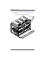
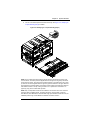
Installing the System Into a Rack............................................................ 3-3
Rack Mounting Hardware ....................................................................... 3-3
Installation ............................................................................................... 3-4
Chapter 4 System Modules ............................................................. 4-1
4-1 Chassis Management Module......................................................... 4-2
Module Redundancy ............................................................................... 4-4
Master/Slave Modules.......................................................................... 4-4
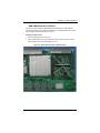
SBM-CMM-001 or SBM-CMM-003 Module Installation .......................... 4-4
BMB-CMM-002 Module Installation ........................................................ 4-5
Configuring the CMM .............................................................................. 4-7
CMM Functions..................................................................................... 4-10
Local KVM.......................................................................................... 4-10
Remote KVM over IP ......................................................................... 4-10
Remote Storage (Virtual Media)......................................................... 4-10
Serial Over LAN (SOL)....................................................................... 4-11
Monitoring Functions.......................................................................... 4-11
Power Consumption Management..................................................... 4-11
CMM Switches and Buttons.................................................................. 4-12
USB Switch ........................................................................................ 4-12
Reset Button ...................................................................................... 4-12
Firmware ............................................................................................... 4-12
vi
Table of Contents
Web-based Management Utility ............................................................ 4-13
Supported Browsers........................................................................... 4-13
Network Connection/Login ................................................................. 4-13
Address Defaults................................................................................ 4-13
Home Page ........................................................................................ 4-14
4-2 Double-Wide and Triple-Wide Modules ....................................... 4-15
Setting up a Double-Wide Bay.............................................................. 4-15
Setting up a Triple Wide Bay................................................................. 4-24
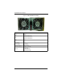
Chapter 5 Power Supply Modules .............................................. 5-1
5-1 Power Supply Modules..................................................................... 5-1
Power Supply Failure.............................................................................. 5-5
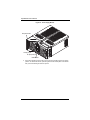
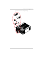
Installing a Power Supply........................................................................ 5-5
Removing a Power Supply...................................................................... 5-5
5-2 Redundant Power Supplies ............................................................. 5-7
5-3 Power Supply Fans ........................................................................... 5-8
5-4 Power Components .......................................................................... 5-9
Power Cord ............................................................................................. 5-9
Power Cord Tie and Clamp................................................................... 5-10
Appendix A System Specifications ...........................................A-1
A-1 Enclosure Specifications..................................................................A-1
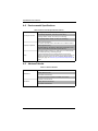
A-2 Environmental Specifications ..........................................................A-2
A-3 Address Defaults...............................................................................A-2
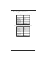
A-4 Power Supply Power Calculations .................................................A-3
vii
SuperBlade User’s Manual
Notes
viii
List of Figures
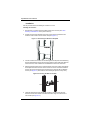
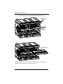
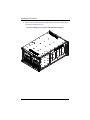
Figure 3-1. Positioning the Enclosure Template ............................................... 3-4
Figure 3-2. Securing the Rails to the Rack ....................................................... 3-4
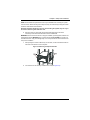
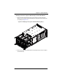
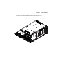
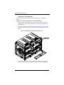
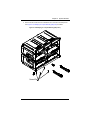
Figure 3-3. Attaching the Optional Handles ...................................................... 3-5
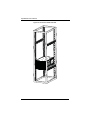
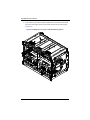
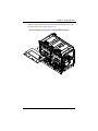
Figure 3-4. Enclosure Installed into Rack ......................................................... 3-6
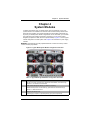
Figure 4-1. Typical Blade System Module Configuration: Rear View ............... 4-1
Figure 4-2. Chassis Management Module ........................................................ 4-3
Figure 4-3. Stand-off Screw Holes on Module Board........................................ 4-5
Figure 4-4. Mini-CMM Mounted on Module Board ............................................ 4-6
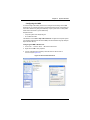
Figure 4-5. Choose Internal Protocol ................................................................ 4-7
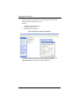
Figure 4-6. Manually Configure the IP Address ................................................ 4-8
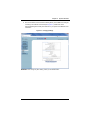
Figure 4-7. Changing Settings .......................................................................... 4-9
Figure 4-8. USB Switch on Rear of CMM ....................................................... 4-12
Figure 4-9. Home Page................................................................................... 4-14
Figure 4-10. Horizontal Spacers for Single Bays ............................................ 4-16
Figure 4-11. Modifying for a Double-Wide Module Bay (Steps 1 & 2) ............ 4-17
Figure 4-12. Modifying for a Double-Wide Module Bay (Steps 3 & 4) ............ 4-18
Figure 4-13. Modifying for an Upper Left Double-Wide Bay (Step 1).............. 4-19
Figure 4-14. Modifying for an Upper Left Double-Wide Bay (Step 3).............. 4-20
Figure 4-15. Modifying for an Upper Left Double-Wide Bay (Step 4).............. 4-21
Figure 4-16. Modifying for an Upper Left Double-Wide Bay (Step 5).............. 4-22
Figure 4-17. Modifying for an Upper Left Double-Wide Bay (Step 6).............. 4-23
Figure 4-18. Modifying for a Triple Wide Bay (Step 1 & 2).............................. 4-24
Figure 4-19. Modifying for a Triple Wide Bay (Step 3 & 4).............................. 4-25
Figure 4-20. Modifying for a Triple Wide Bay (Step 5) .................................... 4-26
Figure 4-21. Modifying for a Triple Wide Bay (Step 6) .................................... 4-27
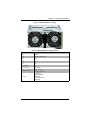
Figure 5-1. PWS-1K62-BR Power Supply......................................................... 5-2
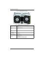
Figure 5-2. PWS-2K53-BR Power Supply......................................................... 5-3
Figure 5-3. PWS-3K01-BR Power Supply......................................................... 5-4
Figure 5-4. Power Supply Module..................................................................... 5-6
Figure 5-5. Blade Status Screen ....................................................................... 5-7
Figure 5-6. Power Components ........................................................................ 5-9
Figure 5-7. Power Cord Tie and Clamp Parts ................................................. 5-10
Figure 5-8. Power Cord Tie and Clamp Assembly.......................................... 5-11
ix
SuperBlade User’s Manual
Notes
x
:
List of Tables
Table 1-1. SuperBlade Enclosures ................................................................... 1-5
Table 1-2. Number of Network Modules that May Be Installed
in each Enclosure.............................................................................................. 1-8
Table 4-1. Typical Blade System Module Configuration: Rear View................. 4-1
Table 4-2. CMM Module Interface..................................................................... 4-3
Table 4-3. CMM Module Features .................................................................... 4-3
Table 4-4. CMM Reset Settings ...................................................................... 4-12
Table 4-5. Address Defaults............................................................................ 4-14
Table 4-6. Home Page Controls...................................................................... 4-15
Table 5-1. PWS-1K62-BR Power Supply Features........................................... 5-2
Table 5-2. PWS-2K53-BR Power Supply Features........................................... 5-3
Table 5-3. PWS-3K01-BR Power Supply Features........................................... 5-4
Table 5-4. Power Components ......................................................................... 5-9
Table A-1. Enclosure Specification Features ....................................................A-1
Table A-2. Environmental Specification Features .............................................A-2
Table A-3. Address Defaults .............................................................................A-2
Table A-4. Power Supply: Power Calculations (PWS-3K01-BR) ......................A-3
Table A-5. Power Supply: Power Calculations (PWS-2K53-BR) ......................A-3
Table A-6. Power Supply: Power Calculations (PWS-1K62-BR) ......................A-4
xi
SuperBlade User’s Manual
Notes
xii
Chapter 1: Introduction
Chapter 1
Introduction
1-1
Overview
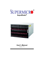
The SuperBlade is a compact self-contained server that connects to a pre-cabled
enclosure that provides power, cooling, management and networking functions. One
enclosure can hold up to either ten or fourteen blade units, depending upon the blade
enclosure used.
In this manual, “blade system” refers to the entire system (including the enclosure and
blades units), “blade” or “blade unit” refers to a single blade module and “blade
enclosure” is the unit that the blades, power supplies and modules are housed in.
Each blade unit is optimized to fit into either a specific ten-blade or fourteen-blade
enclosure.
Please refer to our web site for information on operating systems that have been
certified for use with the SuperBlade (www.supermicro.com/products/superblade/).
1-2
Quick Start Setup
This section covers how to quickly get your new SuperBlade system up and running.
Follow the procedure below to quickly setup your SuperBlade system.
1. Unpack the components of your SuperBlade system and check the packing list for
damaged or missing components.
2. Select a setup location for your system. See "Choosing a Setup Location" on
page 3-1 for details.
3. Setup any double-wide or triple-wide bays if you require any for double-wide or
triple-wide modules in your system. See Section 4-2: Double-Wide and Triple-Wide
Modules on page 4-15 for details.
4. Mount the SuperBlade chassis in your server rack. See "Installing the System Into a
Rack" on page 3-3 for details.
5. Install the power supply modules into the rear of the SuperBlade chasssis. See
"Installing a Power Supply" on page 5-5 for details.
6. Install the CMM module and any InfiniBand or Ethernet modules into the rear of the
SuperBlade chassis.
a. For the CMM module, see "SBM-CMM-001 or SBM-CMM-003 Module Installation" on page 4-4 for details.
b. For the InfiniBand and Ethernet modules, see "SBM-CMM-001 or
SBM-CMM-003 Module Installation" on page 4-4 and the SuperBlade Network
Modules User’s Manual on your system’s CD-ROM.
1-1
SuperBlade User’s Manual
c.
Attach keyboard, mouse and video connections to your CMM module. See
"Local KVM" on page 4-10 for details.
d. Attach network connections for your InfiniBand or Ethernet modules. See the
SuperBlade Network Modules User’s Manual on your system’s CD-ROM for
details.
7. Setup your blade modules for use by doing the following:
a. Open the module case lids of each blade module. See your purchased blade’s
user’s manual on you system’s CD-ROM for details.
b. Install memory into each module. See the the user’s manual for your purchased
blade module from your system’s CD-ROM for details.
c.
Close the module case lids when you have installed your memory for each
blade module. See the the user’s manual for your purchased blade module from
your system’s CD-ROM for details.
d. Install the hard disk drives into each module. See the the user’s manual for your
purchased blade module from your system’s CD-ROM for details.
e. Install your blade modules into your SuperBlade chassis. See the the user’s
manual for your purchased blade module from your system’s CD-ROM for
details.
8. Connect the power cords for your SuperBlade system’s power supply and plug them
into your power source ONLY after you have installed and secured all system
components.
9. Power up your SuperBlade system. Check to be sure all components are operating
right and are not showing any fault LEDs or alarms in their operation.
10. Install your selected operating system for each blade module. See the the user’s
manual for your purchased blade module from your system’s CD-ROM for details.
11. Download a BIOS update for each of your blade modules from the Supermicro
website.
1-3
SuperBlade Solution Systems
DatacenterBlade®, OfficeBlade® and TwinBlade® are three SuperBlade system
product packages that use many of the same blades, modules and components as the
standard SuperBlade system.
DataCenterBlade
The DatacenterBlade system is a blade and enclosure that is configured for data center
and HPC applications. It has a performance and density optimized to achieve 1008
processing cores and 8TB memory, 252 2.5" SAS/SATA/SSD HDD storage per 42U
standard rack. See http://www.supermicro.com/products/SuperBlade/officeblade/ for the
latest details on the Supermicro DatacenterBlade system.
1-2
Chapter 1: Introduction
OfficeBlade
The OfficeBlade system is a blade and enclosure optimized for small-medium business
and personal HPC applications. With acoustically enhanced thermal and cooling
technologies, the OfficeBlade system can operate at or below 50dB with 10 DP server
blades. The OfficeBlade system is best used with Supermicro’s CSE-RACK1U mini-rack
cabinet. See http://www.supermicro.com/products/SuperBlade/officeblade/ for the latest
details on the Supermicro OfficeBlade system.
Some examples of blades that are suitable for use in Office Blade mode are:
•
SBI-7125C-S3
•
SBI-7125C-S3E
•
SBI-7125C-T3
For Office Blade Mode, it is recommended that no more than two 80W Intel Xeon 5400/
5200 series CPUs with 1333 FSB support be used in each blade module.
Twin Blades
Some blade modules for the SuperBlade system contain two (twin) nodes that allow the
blade module to function as effectively two server systems. This allows an enclosure
with these “twin” blades to function with a maximum compute capacity, density and
efficiency of up to 2880 cores, 15TB memory and 240 2.5" SATA HDD or SSD drives in
a 42U rack. See http://www.supermicro.com/products/SuperBlade/TwinBlade/ for the
latest details on the Supermicro TwinBlade system.
NOTE: Due to high power demands, a full enclosure of Twin-node blade modules in an
enclosure requires that you install four PWS-2K53-BR 2500W power modules or higher to
power them.
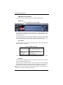
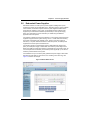
Software Mode Selection
Using the Web-based Management Utility, you can specify your SuperBlade system to
use a different mode for quieter operation and lower fan speed. This is done by selecting
a mode in the CMM OPERATION MODE section of the CMM STATUS screen. This screen
allows you to specify your system to run in either Office Blade Mode (for quieter
operation) or Enterprise Mode (for normal operation). See Section 4-1: Chassis
Management Module on page 4-2 for further details.
1-3
SuperBlade User’s Manual
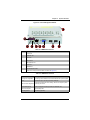
1-4
Product Checklist of Typical Components
•
Blade Enclosure (x1): SBE-710E/Q, SBE-710Q-R90, SBE-720E, SBE-720D-R75 or
SBE-720D-D50 (10-blade series); SBE-714D/E (14-blade series)
•
Blade Unit (minimum of 2, 10 or 14 maximum): See the the Supermicro website
(http://www.supermicro.com/products/superblade/) for a complete list of blades that
can be mounted in your system.
•
Power Supplies (x2): PWS-1K62-BR, PWS-2K01-BR or PWS-2K53-BR,
PWS-3K01-BR
•
CMM Module (x1): SBM-CMM-001 (Not compatible with 720E chassis enclosure),
SBM-CMM-002 (Mini-CMM) and SBM-CMM-003
•
KVM Cable (x1): CBL-0218L
•
Dummy Blade Units: MCP-650-00004-0N (10-blade enclosure) or
MCP-650-00005-0N (14-blade enclosure)
•
Dummy Power Supplies: MCP-650-00001-0N
•
Dummy CMM Modules: MCP-650-00002-0N
•
Dummy GbE Switches: MCP-650-00003-0N
Optional components include:
•
InfiniBand® Switch Module: SBM-IBS-001 or SBM-IBS-Q3618M,
SBM-IBS-Q3616M or SBM-IBS-F3616M (“M” models support BMB-CMM-002
Mini-CMM module)
•
InfiniBand Pass-through Module: SBM-IBP-D14
•
Blade IPMI Add-on Card: AOC-SIMBL
•
Mezzanine Cards (required for operation with the InfiniBand Switch): AOC-IBH-002,
AOC-IBH-XDS, AOC-IBH-XDD, XOC-IBH-XQS and/or AOC-IBH-XQD
•
AOC-XEH-iN2 Add-on Card (required for operation with the 10-Gbps Ethernet
Pass-Through or 10-Gbps Ethernet Switch Modules)
•
Ethernet Switches: SBM-GEM-001 (1-Gbps), SBM-GEM-005 (for SBE-720 series
enclosures and with AOC-GEH-iP2 add-on card), SBM-GEM-X2C+ (1/10-Gbps),
SBM-XEM-X10SM (10-Gbps), SBM-XEM-F8X4SM or SBM-GEM-X3S+
•
Ethernet Pass Through Modules: SBM-GEM-002 (1-Gbps), SBM-GEP-T20
(1-Gbps) or SBM-XEM-002M (10-Gbps)
•
Extra CMM Module for redundancy: SBM-CMM-001, BMB-CMM-002,
SBM-CMM-003
Additional modules will periodically become available. Please refer to http://
www.supermicro.com/products/superblade for the most current list of modules available
for the SuperBlade.
Blade systems install into standard racks. Up to six 7U blade systems may be installed
into a 19" industry standard 42U rack.
1-4
Chapter 1: Introduction
1-5
Blade Enclosure Features
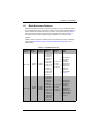
Supermicro's blade enclosures are designed to house from 10 to 14 blade units. Each
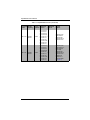
accommodates either two or more power supplies. The enclosure mid-plane allows the
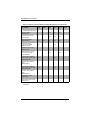
blade units to share certain functions such as power, cooling and networking. Table 1-1
below describes the various enclosures, their components and modules. Table 1-2
shows the number of each module that may be installed in the various enclosure
models.
Please check the Supermicro website for the latest module and enclosure installation
information at http://www.supermicro.com/servers/blade/networking/matrix.cfm for
further details.
Table 1-1. SuperBlade Enclosures
Blade
Enclosure
Module
Model
Capacity
SBE-710E
SBE-710Q
10-blade
Modules
10-blade
Modules
Power
Intel Blade
Supply Options
Options
1620W
2500W
SBI-7127RG-E
SBI-7127R-S6
SBI-7127R-SH
SBI-7126TG
SBI-7126T-S6
SBI-7126T-SH
SBI-7126T-T1E
SBI-7126T-T1L
SBI-7125B-T1
SBI-7125W-S6
SBI-7125C-S3E
SBI-7125C-S3
SBI-7125C-T3
1620W
2500W
3000W
SBI-7127RG-E
SBI-7126T-S6
SBI-7126T-SH
SBI-7127RG
SBI-7126TG
SBI-7126T-S6
SBI-7126T-SH
SBI-7126T-T1E
SBI-7126T-T1L
SBI-7125B-T1
SBI-7125W-S6
SBI-7125C-S3E
SBI-7125C-S3
SBI-7125C-T3
1-5
AMD Blade
Options
Module
Options
SBM-CMM-001 or
BMB-CMM-002
(Mini-CMM)
SBA-7142G-T4 SBM-GEM-001,
SBM-GEM-002 or
SBA-7141A-T
SBM-GEM-X2C+
SBA-7141M-T
SBM-GEM-X3S+
SBA-7121M-T1
SBM-IBS-001
SBM-IBP-D14
SBM-XEM-002M
(See Note 2)
SBM-GEM-X3S+
SBM-CMM-003 or
BMB-CMM-002
(Mini-CMM)
SBA-7142G-T4
SBM-GEM-001,
SBA-7141A-T
SBM-GEM-002 or
SBA-7141M-T SBM-GEM-X2C+
SBA-7121M-T1 SBM-IBS-Q3616 or
SBM-IBS-Q3616M
SBM-XEM-X10SM
(See Note 1)
SuperBlade User’s Manual
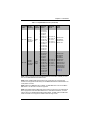
Table 1-1. SuperBlade Enclosures (Continued)
Enclosure Blade
Module
Model
Capacity
SBE-714D
SBE-714E
14-blade
Modules
14-blade
Modules
Power
Intel Blade
Supply
Options Options
AMD Blade
Options
Module
Options
1620W
SBI-7427R-S3
SBI-7427R-T3
SBI-7427R-SH
SBI-7427R-S2L
SBI-7426T-S3
NA
SBI-7426T-T3
SBI-7426T-SH
SBI-7425C-S3E
SBI-7425C-S3
SBI-7425C-T3
SBM-GEM-X3S+
SBM-CMM-001
SBM-GEM-001,
SBM-GEM-002 or
SBM-GEM-X2C+
1620W
SBI-7427R-S3
SBI-7427R-T3
SBI-7427R-SH
SBI-7427R-S2L
SBI-7426T-S3
NA
SBI-7426T-T3
SBI-7426T-SH
SBI-7425C-S3E
SBI-7425C-S3
SBI-7425C-T3
SBM-GEM-X3S+
SBM-CMM-001 or
BMB-CMM-002
(Mini-CMM)
SBM-GEM-001,
SBM-GEM-002 or
SBM-GEM-X2C+
SBM-IBS-001
SBM-IBP-D14
SBM-XEM-002M
(See Note 2)
1-6
Chapter 1: Introduction
Table 1-1. SuperBlade Enclosures (Continued)
Blade
Enclosure
Module
Model
Capacity
SBE-720D
SBE-720E
10-blade
Modules
20 nodes for
TwinBlade
10-blade
Modules
20 nodes for
TwinBlade
Power
Intel Blade
Supply Options
Options
AMD Blade
Options
Module
Options
2500W
(x2)
SBI-7227R-T2
SBI-7127R-S6
SBI-7127-SH
SBI-7126TG
SBI-7226T-T2
SBI-7126T-S6
SBI-7126T-SH
SBI-7126T-T1E
SBI-7126T-T1L
SBI-7125B-T1
SBI-7125W-S6
SBI-7125C-S3E
SBI-7125C-S3
SBI-7125C-T3
SBA-7222G-T2
SBA-7142G-T4
SBA-7141A-T
SBA-7141M-T
SBA-7121M-T1
SBM-GEM-X3S+
SBM-CMM-003
SBM-GEM-X2C+
SBM-GEP-T20
2500W
(x4) or
3000W
SBI-7227R-T2
SBI-7127R-S6
SBI-7127-SH
SBI-7127RG
SBI-7126TG
SBI-7226T-T2
SBI-7126T-S6
SBI-7126T-SH
SBI-7126T-T1E
SBI-7126T-T1L
SBI-7125B-T1
SBI-7125W-S6
SBI-7125C-S3E
SBI-7125C-S3
SBI-7125C-T3
SBM-GEM-X3S+
BMB-CMM-002
(Mini-CMM) or
SBM-CMM-003
SBA-7222G-T2 SBM-GEM-X2C+
SBA-7142G-T4 SBM-GEP-T20
SBA-7141A-T
SBM-IBS-Q3616 or
SBA-7141M-T SBM-IBS-Q3616M
SBA-7121M-T1 SBM-IBS-Q3618 or
SBM-IBS-Q3618M
SBM-XEM-X10SM
(See Note 1)
(See Note 3)
NOTE 1: When supporting the dual InfiniBand QDR and 10-Gb switch modules you must
also use the BMB-CMM-002 Mini-CMM module.
NOTE 2: One InfiniBand DDR switch/pass-through module and one 10-Gb pass-thru
module can be supported simultaneously with the BMB-CMM-002 Mini-CMM installed in the
10-Gb pass-thru module.
NOTE 3: When the SBM-GEP-T20 is installed, one SBM-GEM-X2C+ and one InfiniBand
QDR switch or 10-Gb switch can also be supported.
NOTE 4: The SBE-720E and SBE-720D series enclosures support only one CMM module.
When equipped with redundant QDR IB switches or 10 Gb Ethernet switches, one of the
switches must have a BMB-CMM-002 Mini-CMM installed. The SBE-720E and SBE-720D
series enclosures do not support the InfiniBand Pass-Through module.
1-7
SuperBlade User’s Manual
Table 1-2. Number of Network Modules that May Be Installed in each Enclosure
Name (SKU)
SBE
-720E
SBE
-720D
SBE
-710E
SBE
-710Q
SBE
-714E
SBE
-714D
Max. CMM Modules supported
1
1
2
2
2
1
1G Ethernet Switch
(SBM-GEM-001)
1 or 2
1 or 2
1 or 2
1
1G Ethernet Pass-Through
(SBM-GEM-002)
1 or 2
1 or 2
1 or 2
1
1 or 2
1 or 2
1 or 2
1
1/10G Ethernet Switch
(SBM-GEM-X2C+)
1 or 2
10G Ethernet Switch
w/ option for Mini-CMM
(SBM-XEM-X10SM)
1 or 2
1G Ethernet Pass-Through
(SBM-GEP-T20)
1
1 or 2
1 or 2
2
10G Ethernet Pass-Through
w/ option for Mini-CMM
(SBM-XEM-002M )
1 or 2
1 or 2
QDR 16UL/20DL InfiniBand
Switch w/ option for Mini-CMM
(SBM-IBS-Q3616M)
1 or 2
1 or 2
QDR 16UL/20DL InfiniBand
Switch
(SBM-IBS-Q3616)
1
1
QDR 18UL/18DL InfiniBand
Switch w/ option for Mini-CMM
(SBM-IBS-Q3618M)
1 or 2
1 or 2
QDR 18UL/18DL InfiniBand
Switch
(SBM-IBS-Q3618)
1
1
DDR InfiniBand Switch
(SBM-IBS-001)
1
1
DDR InfiniBand Pass-Through
(SBM-IBP-D14)
1
1
The following sections provide a general outline of the main features for all blade server
enclosures.
1-8
Chapter 1: Introduction
Power
The typical blade enclosure features a 3000W, 2500W, 2000W, 1620W or 1400W power
system composed of two active power supply modules. An alternate configuration (and
required for a full 10 or 14-blade system) features a total of four power supply modules
for redundancy. This power redundancy feature allows you to replace a failed power
module while the backup module takes over to keep the system running. You must have
either two or four power supply modules installed in the blade enclosure (four is
recommended in a full system).
The Chassis Management Module assumes the worst case (maximum) power for any
model of blade prior to applying power. If the power supplies cannot supply that amount
of power, given the current load on the power supplies, then the CMM will not allow that
unit to power up. After a blade is powered up, the blade’s BIOS calculates the actual
power load required by the blade based upon the installed devices and informs the
CMM of its requirements. The CMM then adjust the remaining power for additional
blades based upon the actual power used by the blades that are powered on.
Middle Plane
The middle plane connects the various capabilities of the blades, such as the Gigabit
(GbE) switch(es) to Network Interface Controller(s), the Chassis Management Module
(CMM) to the USB devices and the InfiniBand Switch to the Host Channel Adapters.
These devices all connect to the middle plane through high density connectors that
provide both signals and power. This type of configuration reduces the amount of
system cabling and simplifies the task of setting up the system. It provides an alternative
signals route to support redundant power, CMM, network and IPMI functions.
NOTE: Signaling information can NOT be physically routed from one blade to another.
LEDs
Two LEDs are located at the right top of the enclosure above the last or right most blade.
The left LED provides Power Status information and the right LED is the Fault LED.
Enclosure Cooling
The cooling for the entire blade system is provided by the fans in the power supply
modules. For example, the 2500W and 2000W power supply modules have four fans
per module, whereas the 1600W and 1400W power supply modules have two fans per
module. If a power supply fails, its fans will continue to operate to provide continuous
cooling. For this reason, a failed power supply should remain installed in the enclosure
until a replacement unit is ready.
NOTE: You must install dummy power supplies (MCP-650-00001-0N) in any open power
supply slots in order to prevent air flow leaks that would reduce cooling efficiency in the
blade system’s enclosure.
1-9
SuperBlade User’s Manual
For overheat problems, check that there are no obstructions (such as poorly routed
cables), check that all fans are operating normally and make sure the ambient room
temperature is not too warm (refer to Section A-2: Environmental Specifications on
page A-2 for the maximum operating temperature). You can also use either of the blade
management software utilities to increase the fan speed and maximize system cooling.
In the event of a power overload, you will have to add additional power supply modules
to take up the load. Otherwise, you will not be able to power up all the blade modules.
The blade BIOS plus CMM firmware calculates the load to determine if the power
supplies can adequately handle the total system configuration.
1-6
Power Supply Features
The SuperBlade enclosure comes standard with one CMM module and either two or
four power supplies. Information on the power supplies is summarized below. See
Section 4-1: Chassis Management Module on page 4-2 for details on the CMM module
and Chapter 5 for details on the power supplies.
If you install only two power supplies in the enclosure, they should be installed in the
lower rather than the upper power bays. The reason for this counter-intuitive installation
is that the power supplies in the lower bays provide increased airflow across the
memory modules within each blade module.
Power Supply Modules
Each power supply module has its own power cord. Four modules are required when
the full complement of blade units are installed into an enclosure. An LED on the back of
a power supply will be red when AC power is present and green when the power is on.
Supermicro's high-efficiency blade system power supplies deliver continuous redundant
power up to 94% peak efficiency. Each power supply module includes a management
module that monitors the power supplies and the power enclosure.
Power Cord
Each 3000W, 2500W or 2000W power supply module has a C-20 type socket
(IEC-60320-C20) for AC power and the power cord must have a C-19 type connector
(IEC-60320-C19) to connect to the power supply. Each 1620W power supply module
has a C-14 type socket (IEC-60320-C14) for AC power and the power cord must have a
C-13 type connector (IEC-60320-C13) to connect to the power supply.
WARNING: Please note that ONLY the recommended power cord or an equivalent 14
Gauge power cord should be used for the 1620W/1400W power supply. Typical C13/C14
cords are only 16 Gauge wiring and pose a fire hazard if they are used.
A plastic locking clip partially covering the socket was designed to prevent the power
supply module from being removed with the power cord still connected.
Refer to Appendix A for power/amperage calculation tables.Refer to the supermicro web
site for further details on power cords.
1-10
Chapter 1: Introduction
Power Supply Failure
If a power supply or a fan in a power supply fails, the system management software will
notify you of the situation. In either case, you will need to replace the power supply
module with another identical one. Please note that if a power supply fails, its fans will
continue to operate to provide system cooling. For this reason, a failed power supply
should remain installed in the enclosure until a replacement unit is ready.
See Chapter 5 for the procedure on replacing power supplies.
1-7
Special Design Features
Supermicro's SuperBlade offers special design features, some of which no other blade
server can duplicate. These features give you extraordinary flexibility in configuring a
blade system for your own particular needs.
Operating System Support
Both Microsoft Windows, VMWare and Linux operating systems are supported by the
SuperBlade. Furthermore, you may have different operating systems running on
different blade units within the same blade enclosure.
Remote Management
The Chassis Management Module (CMM) can manage the whole enclosure and any
individual blade module by switching around to it.
Using an optional SIMBL add-on card provides separate IPMI controls for any blade
module that has one installed in it. If your application needs to manage individual blade
units at the same time, just add a SIMBL add-on card to each blade module.
NOTE: Some Blade modules already have onboard BMC.
Computing Density/Power
Dual and quad core processors are supported in the blade module systems. Each
SuperBlade mainboard supports two or four processors and up to 256 GB of main
memory. This translates to a maximum potential of up to 40 processors and 2560 GB of
memory per 7U enclosure or 240 processors and 15 TB of memory for a full 42U rack.
High-Efficiency Power Supplies
A reliable source of power is critical in server systems and even more so in a blade
system, where up to fourteen systems (blades) share the same power source.
SuperBlade power supplies have been designed to operate at up to 94% peak efficiency
and provide redundancy. Using high-efficiency power supplies results in a measurable
reduction in wasted energy consumption and generated heat.
1-11
SuperBlade User’s Manual
1-8
Returning Merchandise for Service
A receipt or copy of your invoice marked with the date of purchase is required before
any warranty service will be rendered. You can obtain service by calling your vendor for
a Returned Merchandise Authorization (RMA) number. When returning to the
manufacturer, the RMA number should be prominately displayed on the outside of the
shipping carton, and mailed prepaid or hand-carried. Shipping and handling charges will
be applied for all orders that must be mailed when service is complete.
This warranty only covers normal consumer use and does not cover damages incurred
in shipping or from failure due to the alteration, misuse, abuse or improper maintenance
of products.
During the warranty period, contact your distributor first for any product problems.
For faster service, RMA authorizations may be requested online at:
http://www. supermicro.com/support/rma/
1-12
Chapter 1: Introduction
1-9
Contacting Supermicro
Headquarters
Address:
Super Micro Computer, Inc.
980 Rock Ave.
San Jose, CA 95131 U.S.A.
Tel:
Fax:
+1 (408) 503-8000
+1 (408) 503-8008
[email protected] (General Information)
Email:
[email protected] (Technical Support)
Website:
www.supermicro.com
Europe
Address:
Super Micro Computer B.V.
Het Sterrenbeeld 28, 5215 ML
‘s-Hertogenbosch, The Netherlands
Tel:
+31 (0) 73-6400390
Fax:
+31 (0) 73-6416525
[email protected] (General Information)
Email:
[email protected] (Technical Support)
[email protected] (Customer Support)
Asia-Pacific
Address:
Super Micro Computer, Inc.
3F, No. 150, Jian 1st Rd.
Zhonghe Dist., New Taipei City 23511
Taiwan (R.O.C)
Tel:
+886-(2) 8226-3990
Fax:
+886-(2) 8226-3992
Website:
www.supermicro.com.tw
Technical Support:
Email:
[email protected]
1-13
SuperBlade User’s Manual
1-14
Chapter 2: Standardized Warning Statements
Chapter 2
Standardized Warning Statements
2-1
About Standardized Warning Statements
The following statements are industry standard warnings, provided to warn the user of
situations which have the potential for bodily injury. Should you have questions or
experience difficulty, contact Supermicro's Technical Support department for assistance.
Only certified technicians should attempt to install or configure components.
Read this appendix in its entirety before installing or configuring components in the
Supermicro chassis
These warnings may also be found on our web site at http://
www.supermicro.com/about/policies/safety_information.cfm.
Warning Definition
Warning!
This warning symbol means danger. You are in a situation that could cause
bodily injury. Before you work on any equipment, be aware of the hazards
involved with electrical circuitry and be familiar with standard practices for preventing
accidents.
警告の定義
この警告サインは危険を意味します。
人身事故につながる可能性がありますので、いずれの機器でも動作させる前に、
電気回路に含まれる危険性に注意して、標準的な事故防止策に精通して下さい。
此警告符号代表危险。
您正处于可能受到严重伤害的工作环境中。在您使用设备开始工作之前,必须充分意识到
触电的危险,并熟练掌握防止事故发生的标准工作程序。请根据每项警告结尾的声明号码
找到此设备的安全性警告说明的翻译文本。
此警告符號代表危險。
您正處於可能身體可能會受損傷的工作環境中。在您使用任何設備之前,請注意觸電的危
險,並且要熟悉預防事故發生的標準工作程序。請依照每一注意事項後的號碼找到相關的
翻譯說明內容。
2-1
SBI-7127RG3 GPU Blade Module User’s Manual
Warnung
WICHTIGE SICHERHEITSHINWEISE
Dieses Warnsymbol bedeutet Gefahr. Sie befinden sich in einer Situation, die zu
Verletzungen führen kann. Machen Sie sich vor der Arbeit mit Geräten mit den Gefahren
elektrischer Schaltungen und den üblichen Verfahren zur Vorbeugung vor Unfällen
vertraut. Suchen Sie mit der am Ende jeder Warnung angegebenen
Anweisungsnummer nach der jeweiligen Übersetzung in den übersetzten
Sicherheitshinweisen, die zusammen mit diesem Gerät ausgeliefert wurden.
BEWAHREN SIE DIESE HINWEISE GUT AUF.
INSTRUCCIONES IMPORTANTES DE SEGURIDAD
Este símbolo de aviso indica peligro. Existe riesgo para su integridad física. Antes de
manipular cualquier equipo, considere los riesgos de la corriente eléctrica y
familiarícese con los procedimientos estándar de prevención de accidentes. Al final de
cada advertencia encontrará el número que le ayudará a encontrar el texto traducido en
el apartado de traducciones que acompaña a este dispositivo.
GUARDE ESTAS INSTRUCCIONES.
IMPORTANTES INFORMATIONS DE SÉCURITÉ
Ce symbole d'avertissement indique un danger. Vous vous trouvez dans une situation
pouvant entraîner des blessures ou des dommages corporels. Avant de travailler sur un
équipement, soyez conscient des dangers liés aux circuits électriques et
familiarisez-vous avec les procédures couramment utilisées pour éviter les accidents.
Pour prendre connaissance des traductions des avertissements figurant dans les
consignes de sécurité traduites qui accompagnent cet appareil, référez-vous au numéro
de l'instruction situé à la fin de chaque avertissement.
CONSERVEZ CES INFORMATIONS.
תקנון הצהרות אזהרה
על מנת להזהיר את המשתמש מפני חבלה,הצהרות הבאות הן אזהרות על פי תקני התעשייה
יש ליצור קשר עם מחלקת תמיכה, במידה ויש שאלות או היתקלות בבעיה כלשהי.פיזית אפשרית
. טכנאים מוסמכים בלבד רשאים להתקין או להגדיר את הרכיבים.טכנית של סופרמיקרו
.יש לקרוא את הנספח במלואו לפני התקנת או הגדרת הרכיבים במארזי סופרמיקרו
. ﺗﺤﺬﯾﺮ!ھﺬا اﻟﺮﻣﺰ ﯾﻌﻨﻲ ﺧﻄﺮ اﻧﻚ ﻓﻲ ﺣﺎﻟﺔ ﯾﻤﻜﻦ أن ﺗﺘﺴﺒﺐ ﻓﻲ اﺻﺎﺑﺔ ﺟﺴﺪﯾﺔ
ﻛﻦ ﻋﻠﻰ ﻋﻠﻢ ﺑﺎﻟﻤﺨﺎطﺮ اﻟﻨﺎﺟﻤﺔ ﻋﻦ اﻟﺪواﺋﺮ،ﻗﺒﻞ أن ﺗﻌﻤﻞ ﻋﻠﻰ أي ﻣﻌﺪات
اﻟﻜﮭﺮﺑﺎﺋﯿﺔ
وﻛﻦ ﻋﻠﻰ دراﯾﺔ ﺑﺎﻟﻤﻤﺎرﺳﺎت اﻟﻮﻗﺎﺋﯿﺔ ﻟﻤﻨﻊ وﻗﻮع أي ﺣﻮادث
اﺳﺘﺨﺪم رﻗﻢ اﻟﺒﯿﺎن اﻟﻤﻨﺼﻮص ﻓﻲ ﻧﮭﺎﯾﺔ ﻛﻞ ﺗﺤﺬﯾﺮ ﻟﻠﻌﺜﻮر ﺗﺮﺟﻤﺘﮭﺎ
안전을 위한 주의사항
2-2
Chapter 2: Standardized Warning Statements
경고 !
이 경고 기호는 위험이 있음을 알려 줍니다 . 작업자의 신체에 부상을 야기 할 수 있는
상태에 있게 됩니다 . 모든 장비에 대한 작업을 수행하기 전에 전기회로와 관련된 위험
요소들을 확인하시고 사전에 사고를 방지할 수 있도록 표준 작업절차를 준수해 주시기
바랍니다 .
해당 번역문을 찾기 위해 각 경고의 마지막 부분에 제공된 경고문 번호를 참조하십시오
BELANGRIJKE VEILIGHEIDSINSTRUCTIES
Dit waarschuwings symbool betekent gevaar. U verkeert in een situatie die lichamelijk
letsel kan veroorzaken. Voordat u aan enige apparatuur gaat werken, dient u zich
bewust te zijn van de bij een elektrische installatie betrokken risico's en dient u op de
hoogte te zijn van de standaard procedures om ongelukken te voorkomen. Gebruik de
nummers aan het eind van elke waarschuwing om deze te herleiden naar de
desbetreffende locatie.
BEWAAR DEZE INSTRUCTIES
Installation Instructions
Warning!
Read the installation instructions before connecting the system to the power
source.
設置手順書
システムを電源に接続する前に、設置手順書をお読み下さい。
警告
将此系统连接电源前 , 请先阅读安装说明。
警告
將系統與電源連接前,請先閱讀安裝說明。
Warnung
Vor dem Anschließen des Systems an die Stromquelle die Installationsanweisungen
lesen.
¡Advertencia!
Lea las instrucciones de instalación antes de conectar el sistema a la red de
alimentación.
Attention
Avant de brancher le système sur la source d'alimentation, consulter les directives
d'installation.
2-3
SBI-7127RG3 GPU Blade Module User’s Manual
.יש לקרוא את הוראות התקנה לפני חיבור המערכת למקור מתח
اﻗﺮ إرﺷﺎدات اﻟﺘﺮﻛﯿﺐ ﻗﺒﻞ ﺗﻮﺻﯿﻞ اﻟﻨﻈﺎم إﻟﻰ ﻣﺼﺪر ﻟﻠﻄﺎﻗﺔ
시스템을 전원에 연결하기 전에 설치 안내를 읽어주십시오 .
Waarschuwing
Raadpleeg de installatie-instructies voordat u het systeem op de voedingsbron aansluit.
Circuit Breaker
Warning!
This product relies on the building's installation for short-circuit (overcurrent)
protection. Ensure that the protective device is rated not greater than: 250 V,
20 A.
サーキット・ブレーカー
この製品は、短絡(過電流)保護装置がある建物での設置を前提としています。
保護装置の定格が 250 V、20 A を超えないことを確認下さい。
警告
此产品的短路 ( 过载电流 ) 保护由建筑物的供电系统提供 , 确保短路保护设备的额定电流
不大于 250V,20A。
警告
此產品的短路 ( 過載電流 ) 保護由建築物的供電系統提供 , 確保短路保護設備的額定電
流不大於 250V,20A。
Warnung
Dieses Produkt ist darauf angewiesen, dass im Gebäude ein Kurzschluss- bzw.
Überstromschutz installiert ist. Stellen Sie sicher, dass der Nennwert der
Schutzvorrichtung nicht mehr als: 250 V, 20 A beträgt.
¡Advertencia!
Este equipo utiliza el sistema de protección contra cortocircuitos (o sobrecorrientes) del
edificio. Asegúrese de que el dispositivo de protección no sea superior a: 250 V, 20 A.
Attention
Pour ce qui est de la protection contre les courts-circuits (surtension), ce produit dépend
de l'installation électrique du local. Vérifiez que le courant nominal du dispositif de
protection n'est pas supérieur à :250 V, 20 A.
יש לוודא כי.מוצר זה מסתמך על הגנה המותקנת במבנים למניעת קצר חשמלי
250 V, 20 A-המכשיר המגן מפני הקצר החשמלי הוא לא יותר מ
2-4
Chapter 2: Standardized Warning Statements
ھﺬا اﻟﻤﻨﺘﺞ ﯾﻌﺘﻤﺪ ﻋﻠﻰ ﻣﻌﺪات اﻟﺤﻤﺎﯾﺔ ﻣﻦ اﻟﺪواﺋﺮاﻟﻘﺼﯿﺮة اﻟﺘﻲ ﺗﻢ ﺗﺜﺒﯿﺘﮭﺎ ﻓﻲ
اﻟﻤﺒﻨﻰ
20A, 250V :ﺗﺄﻛﺪ ﻣﻦ أن ﺗﻘﯿﯿﻢ اﻟﺠﮭﺎز اﻟﻮﻗﺎﺋﻲ ﻟﯿﺲ أﻛﺜﺮ ﻣﻦ
경고 !
이 제품은 전원의 단락 ( 과전류 ) 방지에 대해서 전적으로 건물의 관련 설비에 의존합니
다 . 보호장치의 정격이 반드시 250V( 볼트 ), 20A( 암페어 ) 를 초과하지 않도록 해야
합니다 .
Waarschuwing
Dit product is afhankelijk van de kortsluitbeveiliging (overspanning) van uw electrische
installatie. Controleer of het beveiligde aparaat niet groter gedimensioneerd is dan
220V, 20A.
Power Disconnection Warning
Warning!
The system must be disconnected from all sources of power and the power
cord removed from the power supply module(s) before accessing the chassis
interior to install or remove system components.
電源切断の警告
システムコンポーネントの取り付けまたは取り外しのために、シャーシー内部にアクセ
スするには、
システムの電源はすべてのソースから切断され、電源コードは電源モジュールから取り
外す必要があります。
警告
在你打开机箱并安装或移除内部器件前 , 必须将系统完全断电 , 并移除电源线。
警告
在您打開機殼安裝或移除內部元件前,必須將系統完全斷電,並移除電源線。
Warnung
Das System muss von allen Quellen der Energie und vom Netzanschlusskabel getrennt
sein, das von den Spg.Versorgungsteilmodulen entfernt wird, bevor es auf den
Chassisinnenraum zurückgreift, um Systemsbestandteile anzubringen oder zu
entfernen.
2-5
SBI-7127RG3 GPU Blade Module User’s Manual
¡Advertencia!
El sistema debe ser disconnected de todas las fuentes de energía y del cable eléctrico
quitado de los módulos de fuente de alimentación antes de tener acceso el interior del
chasis para instalar o para quitar componentes de sistema.
Attention
Le système doit être débranché de toutes les sources de puissance ainsi que de son
cordon d'alimentation secteur avant d'accéder à l'intérieur du chassis pour installer ou
enlever des composants de systéme.
אזהרה מפני ניתוק חשמלי
!אזהרה
יש לנתק את המערכת מכל מקורות החשמל ויש להסיר את כבל החשמלי מהספק
.לפני גישה לחלק הפנימי של המארז לצורך התקנת או הסרת רכיבים
ﯾﺠﺐ ﻓﺼﻞ اﻟﻨﻈﺎم ﻣﻦ ﺟﻤﯿﻊ ﻣﺼﺎدر اﻟﻄﺎﻗﺔ وإزاﻟﺔ ﺳﻠﻚ اﻟﻜﮭﺮﺑﺎء ﻣﻦ وﺣﺪة اﻣﺪاد
اﻟﻄﺎﻗﺔ ﻗﺒﻞ
اﻟﻮﺻﻮل إﻟﻰ اﻟﻤﻨﺎطﻖ اﻟﺪاﺧﻠﯿﺔ ﻟﻠﮭﯿﻜﻞ ﻟﺘﺜﺒﯿﺖ أو إزاﻟﺔ ﻣﻜﻮﻧﺎت اﻟﺠﮭﺎز
경고 !
시스템에 부품들을 장착하거나 제거하기 위해서는 섀시 내부에 접근하기 전에 반드시
전원 공급장치로부터 연결되어있는 모든 전원과 전기코드를 분리해주어야 합니다 .
Waarschuwing
Voordat u toegang neemt tot het binnenwerk van de behuizing voor het installeren of
verwijderen van systeem onderdelen, dient u alle spanningsbronnen en alle
stroomkabels aangesloten op de voeding(en) van de behuizing te verwijderen.
Equipment Installation
Warning!
Only trained and qualified personnel should be allowed to install, replace, or
service this equipment.
機器の設置
トレーニングを受け認定された人だけがこの装置の設置、交換、またはサービスを許
可されています。
警告
只有经过培训且具有资格的人员才能进行此设备的安装、更换和维修。
警告
只有經過受訓且具資格人員才可安裝、更換與維修此設備。
2-6
Chapter 2: Standardized Warning Statements
Warnung
Das Installieren, Ersetzen oder Bedienen dieser Ausrüstung sollte nur geschultem,
qualifiziertem Personal gestattet werden.
¡Advertencia!
Solamente el personal calificado debe instalar, reemplazar o utilizar este equipo.
Attention
Il est vivement recommandé de confier l'installation, le remplacement et la maintenance
de ces équipements à des personnels qualifiés et expérimentés.
!אזהרה
. להחליף את הציוד או לתת שירות עבור הציוד,צוות מוסמך בלבד רשאי להתקין
ﯾﺠﺐ أن ﯾﺴﻤﺢ ﻓﻘﻂ ﻟﻠﻤﻮظﻔﯿﻦ اﻟﻤﺆھﻠﯿﻦ واﻟﻤﺪرﺑﯿﻦ ﻟﺘﺮﻛﯿﺐ واﺳﺘﺒﺪال أو ﺧﺪﻣﺔ ھﺬا اﻟﺠﮭﺎز
경고 !
훈련을 받고 공인된 기술자만이 이 장비의 설치 , 교체 또는 서비스를 수행할 수 있습니
다.
Waarschuwing
Deze apparatuur mag alleen worden geïnstalleerd, vervangen of hersteld door
geschoold en gekwalificeerd personeel.
Restricted Area
Warning!
This unit is intended for installation in restricted access areas. A restricted
access area can be accessed only through the use of a special tool, lock and
key, or other means of security. (This warning does not apply to workstations).
アクセス制限区域
このユニットは、アクセス制限区域に設置されることを想定しています。
アクセス制限区域は、特別なツール、鍵と錠前、その他のセキュリティの手段を用い
てのみ出入りが可能です。
警告
此部件应安装在限制进出的场所,限制进出的场所指只能通过使用特殊工具、锁和钥匙或
其它安全手段进出的场所。
警告
此裝置僅限安裝於進出管制區域,進出管制區域係指僅能以特殊工具、鎖頭及鑰匙或其
他安全方式才能進入的區域。
2-7
SBI-7127RG3 GPU Blade Module User’s Manual
Warnung
Diese Einheit ist zur Installation in Bereichen mit beschränktem Zutritt vorgesehen. Der
Zutritt zu derartigen Bereichen ist nur mit einem Spezialwerkzeug, Schloss und
Schlüssel oder einer sonstigen Sicherheitsvorkehrung möglich.
¡Advertencia!
Esta unidad ha sido diseñada para instalación en áreas de acceso restringido. Sólo
puede obtenerse acceso a una de estas áreas mediante la utilización de una
herramienta especial, cerradura con llave u otro medio de seguridad.
Attention
Cet appareil doit être installée dans des zones d'accès réservés. L'accès à une zone
d'accès réservé n'est possible qu'en utilisant un outil spécial, un mécanisme de
verrouillage et une clé, ou tout autre moyen de sécurité.
אזור עם גישה מוגבלת
!אזהרה
הגישה ניתנת בעזרת.יש להתקין את היחידה באזורים שיש בהם הגבלת גישה
.(' מנעול וכד,כלי אבטחה בלבד )מפתח
. ﺗﻢ ﺗﺨﺼﯿﺺ ھﺬه اﻟﻮﺣﺪة ﻟﺘﺮﻛﯿﺒﮭﺎ ﻓﻲ ﻣﻨﺎطﻖ ﻣﺤﻈﻮرة
،ﯾﻤﻜﻦ اﻟﻮﺻﻮل إﻟﻰ ﻣﻨﻄﻘﺔ ﻣﺤﻈﻮرة ﻓﻘﻂ ﻣﻦ ﺧﻼل اﺳﺘﺨﺪام أداة ﺧﺎﺻﺔ
ﻗﻔﻞ وﻣﻔﺘﺎح أو أي وﺳﯿﻠﺔ أﺧﺮى ﻟﻼﻷﻣﺎن
경고 !
이 장치는 접근이 제한된 구역에 설치하도록 되어있습니다 . 특수도구 , 잠금 장치 및 키
, 또는 기타 보안 수단을 통해서만 접근 제한 구역에 들어갈 수 있습니다 .
Waarschuwing
Dit apparaat is bedoeld voor installatie in gebieden met een beperkte toegang. Toegang
tot dergelijke gebieden kunnen alleen verkregen worden door gebruik te maken van
speciaal gereedschap, slot en sleutel of andere veiligheidsmaatregelen.
2-8
Chapter 2: Standardized Warning Statements
Battery Handling
Warning!
There is the danger of explosion if the battery is replaced incorrectly. Replace
the battery only with the same or equivalent type recommended by the
manufacturer. Dispose of used batteries according to the manufacturer's instructions.
電池の取り扱い
電池交換が正しく行われなかった場合、破裂の危険性があります。交換する電池は
メーカーが推奨する型、または同等のものを使用下さい。使用済電池は製造元の指示
に従って処分して下さい。
警告
电池更换不当会有爆炸危险。请只使用同类电池或制造商推荐的功能相当的电池更换原有
电池。请按制造商的说明处理废旧电池。
警告
電池更換不當會有爆炸危險。請使用製造商建議之相同或功能相當的電池更換原有電
池。請按照製造商的說明指示處理廢棄舊電池。
Warnung
Bei Einsetzen einer falschen Batterie besteht Explosionsgefahr. Ersetzen Sie die
Batterie nur durch den gleichen oder vom Hersteller empfohlenen Batterietyp.
Entsorgen Sie die benutzten Batterien nach den Anweisungen des Herstellers.
Attention
Danger d'explosion si la pile n'est pas remplacée correctement. Ne la remplacer que par
une pile de type semblable ou équivalent, recommandée par le fabricant. Jeter les piles
usagées conformément aux instructions du fabricant.
¡Advertencia!
Existe peligro de explosión si la batería se reemplaza de manera incorrecta.
Reemplazar la batería exclusivamente con el mismo tipo o el equivalente recomendado
por el fabricante. Desechar las baterías gastadas según las instrucciones del fabricante.
!אזהרה
יש להחליף.קיימת סכנת פיצוץ של הסוללה במידה והוחלפה בדרך לא תקינה
.את הסוללה בסוג התואם מחברת יצרן מומלצת
.סילוק הסוללות המשומשות יש לבצע לפי הוראות היצרן
ھﻨﺎك ﺧﻄﺮ ﻣﻦ اﻧﻔﺠﺎر ﻓﻲ ﺣﺎﻟﺔ اﺳﺘﺒﺪال اﻟﺒﻄﺎرﯾﺔ ﺑﻄﺮﯾﻘﺔ ﻏﯿﺮ ﺻﺤﯿﺤﺔ ﻓﻌﻠﯿﻚ
اﺳﺘﺒﺪال اﻟﺒﻄﺎرﯾﺔ
ﻓﻘﻂ ﺑﻨﻔﺲ اﻟﻨﻮع أو ﻣﺎ ﯾﻌﺎدﻟﮭﺎ ﻛﻤﺎ أوﺻﺖ ﺑﮫ اﻟﺸﺮﻛﺔ اﻟﻤﺼﻨﻌﺔ
ﺗﺨﻠﺺ ﻣﻦ اﻟﺒﻄﺎرﯾﺎت اﻟﻤﺴﺘﻌﻤﻠﺔ وﻓﻘﺎ ﻟﺘﻌﻠﯿﻤﺎت اﻟﺸﺮﻛﺔ اﻟﺼﺎﻧﻌﺔ
경고 !
2-9
SBI-7127RG3 GPU Blade Module User’s Manual
배터리가 올바르게 교체되지 않으면 폭발의 위험이 있습니다 . 기존 배터리와 동일하거
나 제조사에서 권장하는 동등한 종류의 배터리로만 교체해야 합니다 . 제조사의 안내에
따라 사용된 배터리를 처리하여 주십시오 .
Waarschuwing
Er is ontploffingsgevaar indien de batterij verkeerd vervangen wordt. Vervang de batterij
slechts met hetzelfde of een equivalent type die door de fabrikant aanbevolen wordt.
Gebruikte batterijen dienen overeenkomstig fabrieksvoorschriften afgevoerd te worden.
Redundant Power Supplies
Warning!
This unit might have more than one power supply connection. All connections
must be removed to de-energize the unit.
冗長電源装置
このユニットは複数の電源装置が接続されている場合があります。
ユニットの電源を切るためには、すべての接続を取り外さなければなりません。
警告
此部件连接的电源可能不止一个,必须将所有电源断开才能停止给该部件供电。
警告
此裝置連接的電源可能不只一個,必須切斷所有電源才能停止對該裝置的供電。
Warnung
Dieses Gerät kann mehr als eine Stromzufuhr haben. Um sicherzustellen, dass der
Einheit kein trom zugeführt wird, müssen alle Verbindungen entfernt werden.
¡Advertencia!
Puede que esta unidad tenga más de una conexión para fuentes de alimentación. Para
cortar por completo el suministro de energía, deben desconectarse todas las
conexiones.
Attention
Cette unité peut avoir plus d'une connexion d'alimentation. Pour supprimer toute tension
et tout courant électrique de l'unité, toutes les connexions d'alimentation doivent être
débranchées.
אם קיים יותר מספק אחד
!אזהרה
יש להסיר את כל החיבורים על מנת לרוקן.ליחדה יש יותר מחיבור אחד של ספק
.את היחידה
2-10
Chapter 2: Standardized Warning Statements
.ﻗﺪ ﯾﻜﻮن ﻟﮭﺬا اﻟﺠﮭﺎز ﻋﺪة اﺗﺼﺎﻻت ﺑﻮﺣﺪات اﻣﺪاد اﻟﻄﺎﻗﺔ
ﯾﺠﺐ إزاﻟﺔ ﻛﺎﻓﺔ اﻻﺗﺼﺎﻻت ﻟﻌﺰل اﻟﻮﺣﺪة ﻋﻦ اﻟﻜﮭﺮﺑﺎء
경고 !
이 장치에는 한 개 이상의 전원 공급 단자가 연결되어 있을 수 있습니다 . 이 장치에 전
원을 차단하기 위해서는 모든 연결 단자를 제거해야만 합니다 .
Waarschuwing
Deze eenheid kan meer dan één stroomtoevoeraansluiting bevatten. Alle aansluitingen
dienen verwijderd te worden om het apparaat stroomloos te maken
Backplane Voltage
Warning!
Hazardous voltage or energy is present on the backplane when the system is
operating. Use caution when servicing.
バックプレーンの電圧
システムの稼働中は危険な電圧または電力が、バックプレーン上にかかっています。
修理する際には注意ください。
警告
当系统正在进行时,背板上有很危险的电压或能量,进行维修时务必小心。
警告
當系統正在進行時,背板上有危險的電壓或能量,進行維修時務必小心。
Warnung
Wenn das System in Betrieb ist, treten auf der Rückwandplatine gefährliche
Spannungen oder Energien auf. Vorsicht bei der Wartung.
¡Advertencia!
Cuando el sistema está en funcionamiento, el voltaje del plano trasero es peligroso.
Tenga cuidado cuando lo revise.
Attention
Lorsque le système est en fonctionnement, des tensions électriques circulent sur le fond
de panier. Prendre des précautions lors de la maintenance.
מתח בפנל האחורי
!אזהרה
יש להיזהר במהלך.קיימת סכנת מתח בפנל האחורי בזמן תפעול המערכת
.העבודה
2-11
SBI-7127RG3 GPU Blade Module User’s Manual
ھﻨﺎك ﺧﻄﺮ ﻣﻦ اﻟﺘﯿﺎر اﻟﻜﮭﺮﺑﺎﺋﻲ أواﻟﻄﺎﻗﺔ اﻟﻤﻮﺟﻮدة ﻋﻠﻰ اﻟﻠﻮﺣﺔ
ﻋﻨﺪﻣﺎ ﯾﻜﻮن اﻟﻨﻈﺎم ﯾﻌﻤﻞ ﻛﻦ ﺣﺬرا ﻋﻨﺪ ﺧﺪﻣﺔ ھﺬا اﻟﺠﮭﺎز
경고 !
시스템이 동작 중일 때 후면판 (Backplane) 에는 위험한 전압이나 에너지가 발생 합니
다 . 서비스 작업 시 주의하십시오 .
Waarschuwing
Een gevaarlijke spanning of energie is aanwezig op de backplane wanneer het systeem
in gebruik is. Voorzichtigheid is geboden tijdens het onderhoud.
Comply with Local and National Electrical Codes
Warning!
Installation of the equipment must comply with local and national electrical
codes.
地方および国の電気規格に準拠
機器の取り付けはその地方および国の電気規格に準拠する必要があります。
警告
设备安装必须符合本地与本国电气法规。
警告
設備安裝必須符合本地與本國電氣法規。
Warnung
Die Installation der Geräte muss den Sicherheitsstandards entsprechen.
¡Advertencia!
La instalacion del equipo debe cumplir con las normas de electricidad locales y
nacionales.
Attention
L'équipement doit être installé conformément aux normes électriques nationales et
locales.
תיאום חוקי החשמל הארצי
!אזהרה
.התקנת הציוד חייבת להיות תואמת לחוקי החשמל המקומיים והארציים
ﺗﺮﻛﯿﺐ اﻟﻤﻌﺪات اﻟﻜﮭﺮﺑﺎﺋﯿﺔ ﯾﺠﺐ أن ﯾﻤﺘﺜﻞ ﻟﻠﻘﻮاﻧﯿﻦ اﻟﻤﺤﻠﯿﺔ واﻟﻮطﻨﯿﺔ اﻟﻤﺘﻌﻠﻘﺔ
ﺑﺎﻟﻜﮭﺮﺑﺎء
2-12
Chapter 2: Standardized Warning Statements
경고 !
현 지역 및 국가의 전기 규정에 따라 장비를 설치해야 합니다 .
Waarschuwing
Bij installatie van de apparatuur moet worden voldaan aan de lokale en nationale
elektriciteitsvoorschriften.
Product Disposal
Warning!
Ultimate disposal of this product should be handled according to all national
laws and regulations.
製品の廃棄
この製品を廃棄処分する場合、国の関係する全ての法律・条例に従い処理する必要が
あります。
警告
本产品的废弃处理应根据所有国家的法律和规章进行。
警告
本產品的廢棄處理應根據所有國家的法律和規章進行。
Warnung
Die Entsorgung dieses Produkts sollte gemäß allen Bestimmungen und Gesetzen des
Landes erfolgen.
¡Advertencia!
Al deshacerse por completo de este producto debe seguir todas las leyes y reglamentos
nacionales.
Attention
La mise au rebut ou le recyclage de ce produit sont généralement soumis à des lois et/
ou directives de respect de l'environnement. Renseignez-vous auprès de l'organisme
compétent.
סילוק המוצר
!אזהרה
.סילוק סופי של מוצר זה חייב להיות בהתאם להנחיות וחוקי המדינה
ﻋﻨﺪ اﻟﺘﺨﻠﺺ اﻟﻨﮭﺎﺋﻲ ﻣﻦ ھﺬا اﻟﻤﻨﺘﺞ ﯾﻨﺒﻐﻲ اﻟﺘﻌﺎﻣﻞ ﻣﻌﮫ وﻓﻘﺎ ﻟﺠﻤﯿﻊ اﻟﻘﻮاﻧﯿﻦ واﻟﻠﻮاﺋﺢ اﻟﻮطﻨﯿﺔ
2-13
SBI-7127RG3 GPU Blade Module User’s Manual
경고 !
이 제품은 해당 국가의 관련 법규 및 규정에 따라 폐기되어야 합니다 .
Waarschuwing
De uiteindelijke verwijdering van dit product dient te geschieden in overeenstemming
met alle nationale wetten en reglementen.
Hot Swap Fan Warning
Warning!
The fans might still be turning when you remove the fan assembly from the
chassis. Keep fingers, screwdrivers, and other objects away from the
openings in the fan assembly's housing.
ファン・ホットスワップの警告
シャーシから冷却ファン装置を取り外した際、ファンがまだ回転している可能性があ
ります。ファンの開口部に、指、ドライバー、およびその他のものを近づけないで下
さい。
警告
当您从机架移除风扇装置,风扇可能仍在转动。小心不要将手指、螺丝起子和其他物品太
靠近风扇
警告
當您從機架移除風扇裝置,風扇可能仍在轉動。小心不要將手指、螺絲起子和其他物品
太靠近風扇。
Warnung
Die Lüfter drehen sich u. U. noch, wenn die Lüfterbaugruppe aus dem Chassis
genommen wird. Halten Sie Finger, Schraubendreher und andere Gegenstände von
den Öffnungen des Lüftergehäuses entfernt.
¡Advertencia!
Los ventiladores podran dar vuelta cuando usted quite ell montaje del ventilador del
chasis. Mandtenga los dedos, los destornilladores y todos los objetos lejos de las
aberturas del ventilador
Attention
Il est possible que les ventilateurs soient toujours en rotation lorsque vous retirerez le
bloc ventilateur du châssis. Prenez garde à ce que doigts, tournevis et autres objets
soient éloignés du logement du bloc ventilateur.
!אזהרה
יש. יתכן והמאווררים עדיין עובדים,כאשר מסירים את חלקי המאוורר מהמארז
להרחיק למרחק בטוח את האצבעות וכלי עבודה שונים מהפתחים בתוך המאוורר
2-14
Chapter 2: Standardized Warning Statements
ﻣﻦ اﻟﻤﻤﻜﻦ أن اﻟﻤﺮاوح ﻻ ﺗﺰال ﺗﺪورﻋﻨﺪ إزاﻟﺔ ﻛﺘﻠﺔ اﻟﻤﺮوﺣﺔ ﻣﻦ اﻟﮭﯿﻜﻞ ﯾﺠﺐ إﺑﻘﺎء
اﻷﺻﺎﺑﻊ وﻣﻔﻜﺎت اﻟﺒﺮاﻏﻲ
.وﻏﯿﺮھﺎ ﻣﻦ اﻷﺷﯿﺎء ﺑﻌﯿﺪا ﻋﻦ اﻟﻔﺘﺤﺎت ﻓﻲ ﻛﺘﻠﺔ اﻟﻤﺮوﺣﺔ
경고 !
섀시로부터 팬 조립품을 제거할 때 팬은 여전히 회전하고 있을 수 있습니다 . 팬 조림품
외관의 열려있는 부분들로부터 손가락 및 스크류드라이버 , 다른 물체들이 가까이 하지
않도록 배치해 주십시오 .
Waarschuwing
Het is mogelijk dat de ventilator nog draait tijdens het verwijderen van het
ventilatorsamenstel uit het chassis. Houd uw vingers, schroevendraaiers en eventuele
andere voorwerpen uit de buurt van de openingen in de ventilatorbehuizing.
Power Cable and AC Adapter
Warning!
When installing the product, use the provided or designated connection
cables, power cables and AC adaptors. Using any other cables and adaptors
could cause a malfunction or a fire. Electrical Appliance and Material Safety Law
prohibits the use of UL or CSA -certified cables (that have UL/CSA shown on the code)
for any other electrical devices than products designated by Supermicro only.
電源コードと AC アダプター
製品を設置する場合、提供または指定された接続ケーブル、電源コードと AC アダプ
ターを使用下さい。他のケーブルやアダプタを使用すると故障や火災の原因になるこ
とがあります。電気用品安全法は、UL または CSA 認定のケーブル (UL/CSE マークが
コードに表記 ) を Supermicro が指定する製品以外に使用することを禁止しています。
警告
安装此产品时,请使用本身提供的或指定的连接线,电源线和电源适配器.使用其它线材或
适配器可能会引起故障或火灾。除了 Supermicro 所指定的产品 , 电气用品和材料安全法
律规定禁止使用未经 UL 或 CSA 认证的线材。( 线材上会显示 UL/CSA 符号 )。
警告
安裝此產品時 , 請使用本身提供的或指定的連接線 , 電源線和電源適配器 . 使用其它線
材或適配器可能會引起故障或火災。除了 Supermicro 所指定的產品 , 電氣用品和材料安
全法律規定禁止使用未經 UL 或 CSA 認證的線材。( 線材上會顯示 UL/CSA 符號 )。
2-15
SBI-7127RG3 GPU Blade Module User’s Manual
Warnung
Bei der Installation des Produkts, die zur Verfügung gestellten oder benannt
Anschlusskabel, Stromkabel und Netzteile. Verwendung anderer Kabel und Adapter
kann zu einer Fehlfunktion oder ein Brand entstehen. Elektrische Geräte und Material
Safety Law verbietet die Verwendung von UL-oder CSA-zertifizierte Kabel, UL oder
CSA auf der Code für alle anderen elektrischen Geräte als Produkte von Supermicro
nur bezeichnet gezeigt haben.
¡Advertencia!
Al instalar el producto, utilice los cables de conexión previstos o designados, los cables
y adaptadores de CA. La utilización de otros cables y adaptadores podría ocasionar un
mal funcionamiento o un incendio. Aparatos Eléctricos y la Ley de Seguridad del
Material prohíbe el uso de UL o CSA cables certificados que tienen UL o CSA se
muestra en el código de otros dispositivos eléctricos que los productos designados por
Supermicro solamente.
Attention
Lors de l'installation du produit, utilisez les bables de connection fournis ou désigné.
L'utilisation d'autres cables et adaptateurs peut provoquer un dysfonctionnement ou un
incendie. Appareils électroménagers et de loi sur la sécurité Matériel interdit l'utilisation
de UL ou CSA câbles certifiés qui ont UL ou CSA indiqué sur le code pour tous les
autres appareils électriques que les produits désignés par Supermicro seulement.
AC
חשמליים ומתאמי
!אזהרה
אשרAC ספקים ומתאמים, יש להשתמש בכבלים,כאשר מתקינים את המוצר
שימוש בכל כבל או מתאם אחר יכול לגרום לתקלה או.נועדו וסופקו לשם כך
קיים איסור, על פי חוקי שימוש במכשירי חשמל וחוקי בטיחות.קצר חשמלי
)כשאר מופיע עליהם קוד שלCSA - או בUL -להשתמש בכבלים המוסמכים ב
.( עבור כל מוצר חשמלי אחר שלא צוין על ידי סופרקמיקרו בלבדUL/CSA
واﻟﻜﺎﺑﻼت اﻟﻜﮭﺮﺑﺎﺋﯿﺔ،ﻋﻨﺪ ﺗﺮﻛﯿﺐ اﻟﺠﮭﺎز ﯾﺠﺐ اﺳﺘﺨﺪام ﻛﺎﺑﻼت اﻟﺘﻮﺻﯿﻞ
وﻣﺤﻮﻻت اﻟﺘﯿﺎر اﻟﻤﺘﺮدد
. أن اﺳﺘﺨﺪام أي ﻛﺎﺑﻼت وﻣﺤﻮﻻت أﺧﺮى ﯾﺘﺴﺒﺐ ﻓﻲ ﺣﺪوث ﻋﻄﻞ أو ﺣﺮﯾﻖ. اﻟﺘﻲ
ﺗﻢ ﺗﻮﻓﯿﺮھﺎ ﻟﻚ ﻣﻊ اﻟﻤﻨﺘﺞ
UL أوCSA اﻷﺟﮭﺰة اﻟﻜﮭﺮﺑﺎﺋﯿﺔ وﻣﻮاد ﻗﺎﻧﻮن اﻟﺴﻼﻣﺔ ﯾﺤﻈﺮ اﺳﺘﺨﺪام اﻟﻜﺎﺑﻼت
ﻣﻌﺘﻤﺪة ﻣﻦ ﻗﺒﻞ
Supermicro ﻷي أﺟﮭﺰة ﻛﮭﺮﺑﺎﺋﯿﺔ أﺧﺮى ﻏﯿﺮ اﻟﻤﻨﺘﺠﺎت اﻟﻤﻌﯿﻨﺔ ﻣﻦ ﻗﺒﻞ
(UL/CSA )اﻟﺘﻲ ﺗﺤﻤﻞ ﻋﻼﻣﺔ
2-16
Chapter 2: Standardized Warning Statements
경고 !
제품을 설치할 때에는 제공되거나 지정된 연결케이블과 전원케이블 , AC 어댑터를 사용
해야 합니다 . 그 밖의 다른 케이블들이나 어댑터들은 고장 또는 화재의 원인이 될 수 있
습니다 . 전기용품안전법 (Electrical Appliance and Material Safety Law) 은 슈퍼마
이크로에서 지정한 제품들 외에는 그 밖의 다른 전기 장치들을 위한 UL 또는 CSA 에서
인증한 케이블 ( 전선 위에 UL/CSA 가 표시 ) 들의 사용을 금지합니다 .
Waarschuwing
Bij het installeren van het product, gebruik de meegeleverde of aangewezen kabels,
stroomkabels en adapters. Het gebruik van andere kabels en adapters kan leiden tot
een storing of een brand. Elektrisch apparaat en veiligheidsinformatiebladen wet
verbiedt het gebruik van UL of CSA gecertificeerde kabels die UL of CSA die op de code
voor andere elektrische apparaten dan de producten die door Supermicro alleen.
2-17
SBI-7127RG3 GPU Blade Module User’s Manual
2-18
Chapter 3: Setup and Installation
Chapter 3
Setup and Installation
3-1
Overview
This chapter provides a quick setup procedure for your SuperBlade. Following these
steps in the order given should enable you to have the system operational within a
minimum amount of time. This quick setup assumes that the processor(s) and memory
have already been installed. If not, please turn to Chapter 4 for details on installing
specific components.
3-2
Unpacking the System
You should inspect the box the SuperBlade was shipped in and note if it was damaged
in any way. If the server itself shows damage you should file a damage claim with the
carrier who delivered it.
Decide on a suitable location for the rack unit that will hold the SuperBlade. It should be
situated in a clean, dust-free area that is well ventilated. Avoid areas where heat,
electrical noise and electromagnetic fields are generated. You will also need it placed
near a grounded power outlet. Read the "Rack Precautions" and "Server Precautions" in
the next section.
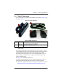
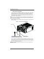
The box the SuperBlade was shipped in should include two sets of rail assemblies, two
handles and the mounting screws you will need to install the system into the rack.
Follow the steps in the order given to complete the installation process in a minimum
amount of time. Please read this section in its entirety before you begin the
installation procedure outlined in the sections that follow.
Choosing a Setup Location
The following are important considerations for choosing a setup location:
•
Leave enough clearance in front of the rack to enable you to remove the blade units
(~25 inches).
•
Leave approximately 30 inches of clearance behind or to the rear of the rack to
allow for sufficient airflow and ease in servicing, as well as clearance for electrical
power connections.
•
This product is intended for installation only in a Restricted Access Location
(dedicated equipment rooms, service closets and the like). This is because the
SuperBlade enclosure does not provide any physical security measures.
•
This product is not suitable for use with visual display work place devices according
to §2 of the German Ordinance for Work with Visual Display Units.
WARNING: Please read the following important Warnings and Precautions!
3-1
SuperBlade User’s Manual
Rack Precautions
The following are important precautions concerning rack setup:
•
The enclosure unit is heavy and requires at least two people to lift it.
•
Ensure that the leveling jacks on the bottom of the rack are fully extended to the
floor with the full weight of the rack resting on them.
•
In single rack installation, stabilizers should be attached to the rack.
•
In multiple rack installations the racks frames should be grounded to the same earth
ground as the electrical source for the power supplies by means of a grounding
strap.
Server Precautions
The following are important precautions concerning server setup:
•
Review the electrical and general safety precautions in Chapter 2.
•
Determine the placement of each component in the rack before you install the rails.
•
Install the heaviest server components on the bottom of the rack first, and then work
up.
•
Use a regulating uninterrupted power supply (UPS) to protect the server from power
surges, voltage spikes and to keep your system operating in case of a power failure.
•
Allow the hot plug hard drives and power supply units to cool before touching them.
•
Always keep the rack's front door and all panels and components on the servers
closed when not servicing to maintain proper cooling.
Rack Mounting Considerations
Below are listed important considerations for rack mounting.
Ambient Operating Temperature
If installed in a closed or multi-unit rack assembly, the ambient operating temperature of
the rack environment may be greater than the ambient temperature of the room.
Therefore, consideration should be given to installing the equipment in an environment
compatible with the manufacturer’s maximum rated ambient temperature. Refer to
Appendix E for operating temperature specifications.
Reduced Airflow
Equipment should be mounted into a rack so that the amount of airflow required for safe
operation is not compromised.
Mechanical Loading
Equipment should be mounted into a rack so that a hazardous condition does not arise
due to uneven mechanical loading.
3-2
Chapter 3: Setup and Installation
Circuit Overloading
Consideration should be given to the connection of the equipment to the power supply
circuitry and the effect that any possible overloading of circuits might have on
over-current protection and power supply wiring. Appropriate consideration of
equipment nameplate ratings should be used when addressing this concern. See the
power calculation tables in Appendix A.
Reliable Ground
A reliable ground must be maintained at all times. To ensure this, the rack itself should
be grounded. Particular attention should be given to power supply connections other
than the direct connections to the branch circuit (such as the use of power strips and so
on).
NOTE: It is recommended that you seek the advice and assistance of a licensed electrician
that can advise you on best practices for ensuring that the electrical supply and the rack are
joined to a Common Bonding Network.
Professional documents on grounding techniques include:
•
ANSI/TIA-942 – Telecommunications Infrastructure Standard for Data Centers
•
J-STD-607-A-2002 – Commercial Building Grounding (Earthing) and Bonding
Requirements for Telecommunications
•
IEEE Std 1100™-2005 (IEEE Emerald Book) – IEEE Recommended Practice for
Powering and Grounding Electronic Equipment
Installing the System Into a Rack
This section provides information on installing the SuperBlade into a rack. There are a
variety of rack units on the market, meaning the procedure may differ slightly. Refer to
the Enclosure Template that was included with the system for help.
Rack Mounting Hardware
The following is a list of rack mounting hardware you will need for rack setup and
installation:
•
Two rail assemblies (one for each side of the enclosure)
•
Two handles
•
Four roundhead screws for fastening the enclosure ears to the rack
•
Eight flathead screws and washers for mounting the rails to the rack
3-3
SuperBlade User’s Manual
Installation
Use the procedure below for installing an enclosure in a rack.
Installing an enclosure:
1. Decide where you want to place the blade enclosure into the rack (see "Rack
Mounting Considerations" in the previous section).
2. Position the Enclosure Template at the front of the enclosure to determine the
locations of the screws for the enclosure rails (see Figure 3-1).
Figure 3-1. Positioning the Enclosure Template
3. The two enclosure rail sections are screwed together to keep them immobile during
shipping. Release these screws just enough to allow the rails to slide apart. Note the
arrow on the rail, which indicates the end that attaches to the front of the rack.
4. Slide the rails apart far enough to match the depth of the rack. Position the rails with
the template and secure the front of each to the front of the rack with two flathead
screws, then secure the back of each rail to the rear of the rack with two flathead
screws (see Figure 3-2). Note that the rails are left/right specific and very heavy.
Figure 3-2. Securing the Rails to the Rack
5. (Optional step) Add the front left and right handles to the enclosure using five
screws to secure each handle. Install a thumbscrew through the bottom hole of
each handle (see Figure 3-3).
3-4
Chapter 3: Setup and Installation
NOTE: These handles are optional and need only be installed when mounting the system
into a short rack. When mounting into a deep rack, they are unnecessary and regular screws
should be used instead of thumbscrews.
Be aware that these handles are not to be used for lifting the system, they are only to
be used to slide the system within the rack.
6. With one person on either side (see the descriptive label on the side of the
enclosure), lift the enclosure and slide it into the installed rails.
WARNING: Be sure that the enclosure is empty of all blades, power supplies, switches and
management modules BEFORE lifting. These should be installed AFTER the enclosure is
mounted in the rack. Injury and damage may occur if components are not removed from the
rack prior to installation.
7. After pushing the enclosure all the way into the rack, use two roundhead screws on
each side of the server to lock it into place.
Figure 3-3. Attaching the Optional Handles
8. The enclosure is now securely installed in the rack (see Figure 3-4).
3-5
SuperBlade User’s Manual
Figure 3-4. Enclosure Installed into Rack
3-6
Chapter 4: System Modules
Chapter 4
System Modules
In addition to the blade units, your blade system comes equipped with one or more
system modules. The modules fit into the rear of the enclosure into bays above and/or
below the power supplies. This chapter describes the various blade modules that may
be part of your blade system. Module configurations can be customized; you can install
two of the same type module for redundancy purposes or you may omit a module
altogether (except for the CMM, which is a required module). Figure 4-1 shows a typical
module configuration in a blade system. See Chapter 5 for information on power supply
modules.
WARNING: All module bays must be populated either with a module or a dummy module
cover to maintain proper airflow.
Figure 4-1. Typical Blade System Module Configuration: Rear View
1
4
2
5
5
5
5
1
3
Table 4-1. Typical Blade System Module Configuration: Rear View
Item#
Description
1
This bay can hold any of the following: 1Gb Ethernet Switch Module, 1Gb Pass-through
Module or a 1/10 Gb Ethernet Switch Module
2
CMM (Chassis Management Module) (x1 standard, x2 optional)
3
InfiniBand Switch (shown in double-wide bay), optional Ethernet 10Gb Pass-through
Module, or a 10Gb Ethernet switch
4
Empty bay with dummy cover
5
Power Supply (x2 required, x4 optional depending upon system requirements)
4-1
SuperBlade User’s Manual
NOTE: See the SuperBlade Network Modules User’s Manual on your enclosed CD-ROM
disc for details on all 1Gb Ethernet modules, 1Gb pass-through modules, 1/10Gb Ethernet
modules, 10Gb Ethernet pass-through modules, 10 Gb Ethernet Switch module and
InfiniBand modules for the SuperBlade system.
4-1
Chassis Management Module
The Chassis Management Module (CMM) (Figure 4-2) is a required module in a blade
system. This “command” module communicates with the blade units, the power supplies
and the blade switches. Used in conjunction with the Web Interface or IPMI View
management software, the CMM provides administrator control over individual blade
units, power supplies, cooling fans and networking switches and monitors onboard
temperatures, power status, voltage levels and fan speeds. There are several models of
CMM modules that may be used with your system. These include:
•
SBM-CMM-001 – This is the standard CMM module used with the SBE-710E,
SBE-714D and SBE-714E blade enclosures. This CMM module can support up to
14 blade modules.
•
BMB-CMM-002 – Sometimes referred to as a “Mini-CMM”, this is an add-on card for
chassis management that is installed in double-wide networking modules such as
the 10 Gb Ethernet Pass-through Module, the 10 Gb Ethernet Switch, or InfiniBand
QDR switches. It performs the standard CMM functions and is accessible through
external ports on the associated networking module. Use of the BMB-CMM-002,
where applicable, allows installation of redundant networking modules since it
installs inside a networking module and does not need a separate bay for it in the
blade enclosure. This Mini-CMM can support up to 20 blade modules.
•
SBM-CMM-003 – This CMM module is slightly taller in size than the SBM-CMM-001
module and is used only with the SBE-720E or SBE-710Q blade enclosures. It has
the same features as the SBM-CMM-001 CMM module. This CMM module can
support up to 20 blade modules.
The CMM provides a dedicated, local and remote KVM (keyboard/video/mouse)
connection over an out of band TCP/IP Ethernet network during any server state
(functioning, blue-screen, powered down, BIOS and so on). It also supports Virtual
Media (VM) redirection for CD, floppy and USB mass storage devices and configures
such information as the switch IP addresses. A summary of CMM features is shown in
Table 4-3.
NOTE: The SBM-CMM-002 is accessible through a high-density connector in the back of
the pass-through module or InfiniBand module it is installed in.
4-2
Chapter 4: System Modules
Figure 4-2. Chassis Management Module
9
8
1
2
3
4
5
6
7
Table 4-2. CMM Module Interface
Item#
Description
1
Power LED
2
Heartbeat LED
3
Fault LED
4
Ethernet Port
5
VGA (Monitor) Port
6
USB Ports
7
Reset Button
8
Module Release Handle
9
USB 2.0/1.1 Switch (accessed at back of module, see Figure 4-8)
Table 4-3. CMM Module Features
Feature
Description
Management Capabilities
Can manage 10 to 20 blade units, network modules and 4 power supplies
Ports
One Ethernet port, one VGA port and two USB ports
Basic Functions Supported
Local KVM, remote KVM, remote storage, Serial-over-LAN (SOL), blade
monitoring and control
System Management
System management interface provided via dedicated LAN
Power Consumption
Approximately 20W
Operating System
Firmware (upgradable)
4-3
SuperBlade User’s Manual
Module Redundancy
A blade system must have one CMM and may have two for redundancy. Since the CMM
uses its own processor, all monitoring and control functions are carried out regardless of
the operation or power status of the blade units. CMM modules can only be installed in
the upper and/or lower right module bays. Twin-node blade module chassis enclosures
can only accomodate one CMM module.
The redundancy feature is automatic when two CMM modules have been installed into a
blade system.
Master/Slave Modules
When a blade system has two CMM modules, they are assigned a master/slave status.
This is done automatically according to the following criteria:
Determining Master/Slave status:
1. The CMM installed in the upper bay will be the master, however...
2. If the master CMM is powered down or removed (or is being reset by its user), the
second (slave) CMM module will then immediately be assigned as the master.
NOTE: The Slave CMM keeps the same log/status as the Master CMM.
SBM-CMM-001 or SBM-CMM-003 Module Installation
Use this procedure to install the SBM-CMM-001 or SBM-CMM-003 CMM modules to the
SuperBlade chassis. Make sure the cover to the module has been installed before
proceeding. Follow the anti-static precautions described in Chapter 2.
Installing the Module:
1. Remove the dummy cover from the bay you want to place the module in.
2. Place the module's release handle in the open position.
3. Slide the module into the module bay until it stops.
4. Push the release handle to the closed position.
5. After the module has been installed and the handle locked, it will turn on and a
POST test will run to verify it is working properly.
Removing the Module:
1. Pull out the release handle to the open position.
2. Pull the module out of the bay.
3. Replace immediately with another module or with a dummy module cover to
maintain airflow integrity.
4-4
Chapter 4: System Modules
BMB-CMM-002 Module Installation
Use this procedure to install the BMB-CMM-002 Mini-CMM to the 10 Gb Ethernet
Pass-through Module, the 10 Gb Ethernet Switch or an InfiniBand QDR switch. Follow
the anti-static precautions described in Chapter 2.
Installing the Add-on Card
1. Remove the switch/module’s top cover.
2. Align the Mini-CMM mounting holes with the stand off screw holes on the switch
board module and insert the Mini CMM (Figure 4-3).
Figure 4-3. Stand-off Screw Holes on Module Board
Stand-off Screw Holes
4-5
SuperBlade User’s Manual
3. Fasten the screws to secure the Mini-CMM (Figure 4-4).
Figure 4-4. Mini-CMM Mounted on Module Board
Screws
4. Replace and re-secure the switch/module’s cover.
Removing the Add-on Card
1. Remove the switch/module’s top cover.
2. Unscrew the Mini-CMM from its mountings in the switch/module and remove it.
3. Replace and re-secure the switch/module’s cover.
4-6
Chapter 4: System Modules
Configuring the CMM
To access/configure the CMM, you first have to configure the IP settings of the CMM
depending on you network environment. The below procedure for this configuration just
serves as a reference for getting the CMM setup. If your system has Linux OS, please
follow similar instructions to get the CMM setup.
Requirements are:
•
Computer system with LAN (RJ45) port
•
RJ -45 Ethernet cable
The default IP of the CMM is https://192.168.100.100. Configure the Computer system
(connected through Ethernet-LAN to the CMM) to the same address range (for example
https://192.168.100.101).
Configuring the CMM in Windows OS:
1. Go to START CONTROL PANEL NETWORK CONNECTIONS
2. Right-click on LAN to view properties.
3. Choose “Internet Protocol (TCP/IP)” under the GENERAL tab and click on
PROPERTIES (see Figure 4-5 ).
Figure 4-5. Choose Internal Protocol
4-7
SuperBlade User’s Manual
4. Manually configure the IP address of the computer system to be in the same
address range as the CMM (see Figure 4-6).
Example:
•
IP address: https://192.168.100.101
•
Subnet Mask: 255.255.255.0
•
Default Gateway: 192.168.100.1
Figure 4-6. Manually Configure the IP Address
5. Once the IP address for the computer system is configured, the CMM can be
accessed through the web browser by entering the default IP address
192.168.100.100 of the CMM into the browser’s address bar.
4-8
Chapter 4: System Modules
6. Now, the IP address, subnet mask and default gateway of the CMM can be changed
according to the network environment (see Figure 4-7). Please refer to the
Web-based Management Utility User’s Manual on your system’s CD-ROM for more
information.
Figure 4-7. Changing Settings
WARNING: Don't change any other setting, unless you are familiar with it.
4-9
SuperBlade User’s Manual
CMM Functions
The following sections describe local functions and remote functions of the CMM. With
only minor exceptions, all of the remote functions can be performed by one of three
mechanisms: web-based access to the CMM module, access to the CMM using
IPMIview, a client tool implemented in Java, or via IPMItool commands (DOS
commands or shell scripted commands).
When the web based browser is used, the CMM acts as a web server, requiring a higher
bandwidth connection to the CMM. If there are any bandwidth constraints, IPMI will
provide a superior experience. Additionally, since graphical updates are provided by
client-side Java, IPMIview can also be a superior user experience.
IPMItool on the other hand can provide the ability to issue similar/identical commands to
many SuperBlade enclosures/CMM’s to manage all of them in a similar way.
In addition to accessing the SuperBlade capabilities through CMM, they can also be
accessed directly on a blade by blade basis if the blades are equipped with SIMBL to
provide IPMI control of each individual blade.
Local KVM
KVM stands for Keyboard/Video/Mouse. With KVM, a user can control multiple blades
with a single keyboard/video/mouse setup. The maximum video resolution the KVM can
support is 1280 x 1024 @ 60 Hz.
To Use: Connect your keyboard, mouse and monitor to the USB and VGA connectors
on the CMM module, then push the KVM button on the control panel of the blade
module you wish to access. The KVM LED on the blade will then illuminate and you can
interface directly with that blade. To access a different blade module, simply push the
KVM button on that blade's control panel.
Remote KVM over IP
Remote KVM over IP is independent from local KVM (although local KVM can operate in
parallel with Remote KVM). Remote KVM encrypts all communication between the
remote user and the CMM.
To Use: Remote KVM over IP is initiated with the management software (IPMI View or
Web-based utility). Attach the LAN cable to the LAN port on the CMM module then refer
to "Web-based Management Utility" on page 4-13 to login and use either utility.
Remote Storage (Virtual Media)
The Remote Storage function allows the user to connect to a remote storage device
(such as a floppy, hard disk, CD-ROM or USB storage device) and access the device as
if it were local. This can be used not only to read and write to remote storage devices but
to load an operating system from a remote drive.
4-10
Chapter 4: System Modules
Serial Over LAN (SOL)
Serial Over LAN allows you to redirect the input and output of a serial port via IPMI in
order to manage blade modules from a remote location.
To Use: Serial Over LAN can be activated via the Web-based Management utility. See
the Web-based Management Utility User’s Manual on your system’s CD-ROM for the
procedure to initiate SOL.
Monitoring Functions
Used in conjunction with IPMI or the Web-based Management utility, the CMM module
can monitor and provide information on the hardware health of the blade modules and
the system as a whole. In addition to the monitoring functions, you can remotely power
on, power off or reboot a system.
Health information includes:
•
Temperature levels
•
Fan speeds
•
Voltage levels
•
Power status
Power Consumption Management
The CMM module’s firmware can also control all power on/off activity in the whole blade
system. This is done by using the Power button, via a SIMBL add-on card, onboard
BMC or from any other use of remote management software.
Once a blade module is installed in the enclosure the installed CMM immediately
receives information on the rated Max Power Consumption value of the new blade
module. The CMM then calculates whether there is enough power for this new blade
module by comparing the Max Power Consumption value of the new blade module with
the calculated Remaining Power value of the system.
If there is enough power, the CMM will power on the blade. However if there is not
enough power in the blade system, then the new blade module is not powered on and
the front panel LED on the enclosure will blink.
After the blade is powered on, the CMM then collects the actual power consumption of
this individual blade and updates the calculated Remaining Power value for the system.
The CMM also reserves power for all the networking and chassis management modules
installed on the system.
NOTE: Blade modules with a SIMBL add-on card installed or onboard BMC in them provide
individual IPMI for each blade unit. It communicates with the CMM for remote web or IPMI
View access.
WARNING: One CMM module must be running to control the power systems and prevent
overloading.
4-11
SuperBlade User’s Manual
CMM Switches and Buttons
The various switches and buttons found on the CMM are described below.
USB Switch
Figure 4-8. USB Switch on Rear of CMM
The USB ports on the CMM can function in either 2.0 or 1.1 mode (the default is 1.1). A
switch located on the PCB at the back of the CMM module is used to change the USB
mode (see Figure 4-8).
To access the switch, you need to remove the CMM from the enclosure. Pull the CMM
out and locate the switch near the large gray connector. The settings are silk screened
on the PCB. After setting the switch, insert the CMM module back into its bay.
Reset Button
The Reset button located on the front of the CMM module is used to reset the following
software settings to their defaults:
Table 4-4. CMM Reset Settings
Software Setting
Default
User Name and Password
Reset to ADMIN and ADMIN (case sensitive)
IP Address
Reset to https://192.168.100.100
Gateway Address
Reset to 0.0.0.0
Subnet Mask
Reset to 255.255.255.0
To reset the CMM to factory defaults, press and hold the Reset button for five seconds.
Firmware
The firmware for the CMM switch resides in the module. This firmware can be updated
with the web-based management utility.
Within the utility, go to the MAINTENANCE > UPDATE FIRMWARE screen in the Web-based
Management Utility. Here you can enter the name of the firmware you want to update or
click on BROWSE to select the firmware file. Finish by clicking the UPLOAD button.
NOTE: This process is not reversible once the firmware is updated, so proceed with caution.
It might take a few minutes to complete this procedure.
4-12
Chapter 4: System Modules
Web-based Management Utility
System management may be performed with either of three software packages:
IPMIview, SMCIPMItool or a Web-based Management Utility. Any of these utilities are
designed to provide an administrator with a comprehensive set of functions and
monitored data to keep tabs on the system and perform management activities.
The Web-based Management Utility is a web-based interface that consolidates and
simplifies system management for Supermicro SuperBlade systems. The Web-based
Management Utility aggregates and displays data from the CMM module.
NOTE: Full documentation on the Web-based Management Utility may be found on the
CD-ROM included with your system.
The Web-based Management Utility provides the following key management features:
•
Enables IT administrators to view in-depth hardware configuration and status
information using a single intuitive interface.
•
Provides an OS-independent, remote graphical console.
•
Allows remote users to map local media (floppy, CD-ROM, removable disks and
hard drives) or ISO images on a shared network drive to a blade server.
Supported Browsers
The following browsers have been tested for use with the Web-based Management
Utility. It is recommended that you use the most current revision of the browser you
choose. The minimum browser revisions supported by the Web-based Management
Utility are shown below:
•
Internet Explorer 7
•
Firefox 2.0.0.7
•
Netscape 9.03b
Network Connection/Login
To log into the Web-based Management Utility:
1. Launch a web browser.
2. In the address field of the browser, enter the IP address that you assigned to the
Chassis Management Module and hit the <ENTER> key.
3. When the browser makes contact with Supermicro’s Chassis Management Module,
enter your username and password, then click LOGIN.
4. The WEB-BASED MANAGEMENT UTILITY HOME PAGE will then display as shown in
Figure 4-9.
Address Defaults
Table 4-5 shows the default addresses that are initially set for the CMM. Afterwards, you
can change these values within the program (see the Web-based Management Utility
User’s Manual on your system’s enclosed CD-ROM for more details).
4-13
SuperBlade User’s Manual
Table 4-5. Address Defaults
Default
Description
Default IP Address
https://192.168.100.100a
Default Gateway Address
0.0.0.0
Default Subnet Mask
255.255.255.0
Default username
ADMIN
Default password
ADMIN
a. Note: The web address must be entered as https://
192.168.100.100 in the web browser. Entering only http:// gives you
instead an address error.
Home Page
Figure 4-9 and Table 4-6 respectively display the WEB-BASED MANAGEMENT UTILITY
HOME PAGE and its controls.
Figure 4-9. Home Page
1
2
4
3
6
5
4-14
Chapter 4: System Modules
Table 4-6. Home Page Controls
Item
Description
1
Home: Click this icon to return to the Home Page.
2
Console: Click this icon to open the Remote Console Screen. (KVM must first be initialized
either with the KVM button or via management software).
3
Remote Console Screen: The active screen from the remote console is displayed here.
Clicking on this window also accesses the remote console.
4
Logout: Click on this icon to log out.
5
Refresh: Click on this icon to refresh the remote console preview screen.
6
Main Menu Icons: Used to initiate the various functions in the Web-based Management
Utility.
NOTE: For more information on the Web-based Management Utility, see the Web-based
Management Utility User’s Manual on the CD-ROM included with your SuperBlade system.
4-2
Double-Wide and Triple-Wide Modules
Most modules in the SuperBlade fit into single-wide bays. The InfiniBand module and
some other modules however (such as the 10GbE Pass-through module and 10 Gb
Switch Module), require a double-wide bay. Some need a triple-wide bay (such as the
SBM-IBP-D14 InfniBand Pass-through Module) that are created by combining three
bays. The enclosure's module bays are designed to be easily modified from single to
double-wide/triple-wide width by following the procedures below.
Setting up a Double-Wide Bay
Some modules require that you set up a double-wide bay on the right side while some
modules (such as the SBM-GEP-T20) require that you modify the enclosure to support
double-wide modules in an upper left module bay. Use the procedures below to modify
the enclosure for double-wide bays.
Modifying an Enclosure’s Module Bays for Right Side Double-wide Modules
1. Remove the four screws that secure the inner enclosure to the main enclosure.
Slide the inner enclosure outward, depressing the locking tabs on both sides to pull
it completely out.
2. Remove any single-wide modules that are occupying the bays you wish to modify to
a double-wide bay.
3. In the module bay you wish to expand to double-wide, remove the two screws that
secure the center support to the inner enclosure then take out the center support.
See Figure 4-11, Step 1 for details.
4. Remove the two screws from the underside of each of the two horizontal spacers
(as shown in Figure 4-10). See Figure 4-11, Step 2 for details.
5. Using four screws, install the long horizontal spacer to the same space where the
two short spacers were removed. See Figure 4-12, Step 3 for details.
4-15
SuperBlade User’s Manual
6. You can now install a double-wide module into the bay. See Figure 4-12, Step 4 for
details.
NOTE: This procedure describes modifying two right most single-wide bays located at the
top of the inner enclosure. The same procedure applies to the two right most single bays
located at the bottom of the enclosure, but note that the horizontal spacers in the bottom
bays use a guide pin and are not interchangeable with the upper bay spacers (see
Figure 4-10 for details). Modules in the upper left hand bays will have their release handles
on the bottom, while all modules in the lower bays will have their release handles on the top.
Placing modules in an “upside-down” orientation in the upper-left corner (only) does not
affect their operation.
NOTE: Unless it is capable of supporting the mini-CMM, only one double-wide module can
be installed in an enclosure since each enclosure requires at least one CMM module. The
bottom location is recommended. If using the AOC-IBH-002, AOC-IBH-XQS or
AOC-IBH-XDS single-port InfiniBand mezzanine card, the InfiniBand switch MUST be
installed in the bottom location.
Figure 4-10. Horizontal Spacers for Single Bays
MCP-560-00012-1N (for top bay)
MCP-560-00009-1N (for bottom bay)
4-16
Chapter 4: System Modules
Figure 4-11. Modifying for a Double-Wide Module Bay (Steps 1 & 2)
Step 1
Center Support
Screws (2)
Center
Support
Step 2
Horizontal Spacer
Screws (4)
Horizontal Spacers (2)
(MCP-560-00012-1N)
4-17
SuperBlade User’s Manual
Figure 4-12. Modifying for a Double-Wide Module Bay (Steps 3 & 4)
Step 3
Horizontal Spacer
Screws (4)
Horizontal
Spacers (1)
Step 4
Double-Wide Module
NOTE: For purposes of illustration the chassis in the above images is inverted to show
installation for a double-wide module in the chassis bottom.
4-18
Chapter 4: System Modules
Modifying an Enclosure’s Upper-Left Module Bays for Double Wide Modules
1. Remove the four screws that secure the inner enclosure to the main enclosure.
Slide the inner enclosure outward, depressing the locking tabs on both sides to pull
it completely out (Figure 4-13).
Figure 4-13. Modifying for an Upper Left Double-Wide Bay (Step 1)
2. Remove any single-wide modules that are occupying the bays you wish to modify to
a double-wide bay.
4-19
SuperBlade User’s Manual
3. In the module bay you wish to expand to double-wide, remove the two screws that
secure the center support to the inner enclosure then take out the center support
(Figure 4-14).
Figure 4-14. Modifying for an Upper Left Double-Wide Bay (Step 3)
4-20
Chapter 4: System Modules
4. Install the horizontal spacer plate into the new double-wide bay and secure it with
four screws into the inner enclosure (Figure 4-15).
Figure 4-15. Modifying for an Upper Left Double-Wide Bay (Step 4)
4-21
SuperBlade User’s Manual
5. Slide the inner enclosure back into the blade enclosure and secure it again with the
four securing screws (Figure 4-16).
Figure 4-16. Modifying for an Upper Left Double-Wide Bay (Step 5)
4-22
Chapter 4: System Modules
6. You can now install a double-wide module into the bay (Figure 4-17).
Figure 4-17. Modifying for an Upper Left Double-Wide Bay (Step 6)
4-23
SuperBlade User’s Manual
Setting up a Triple Wide Bay
Use the procedure below for installing a triple-wide module bay in a SuperBlade
chassis.
Modifying an Enclosure’s Module Bays for Triple-Wide Modules
1. Remove the four screws that secure the inner enclosure to the main enclosure.
Slide the inner enclosure outward, depressing the locking tabs on both sides to pull
it completely out.
2. Remove any single-wide modules that are occupying the bays you wish to modify to
a triple-wide bay. See Figure 4-18, Modifying for a Triple Wide Bay (Step 1 & 2) for
details.
Figure 4-18. Modifying for a Triple Wide Bay (Step 1 & 2)
Screws 4pcs
3. In the module bay you wish to expand to triple wide, remove the two screws that
secure the center support to the inner enclosure then take out the center support.
4-24
Chapter 4: System Modules
4. Remove the two screws from the underside of each of the two horizontal spacers.
See Figure 4-19, Modifying for a Triple Wide Bay (Step 3 & 4) for details.
Figure 4-19. Modifying for a Triple Wide Bay (Step 3 & 4)
Screws 4Pcs
4-25
SuperBlade User’s Manual
5. Using four screws, install the long horizontal spacer to the same space where the
two short spacers were removed. See Figure 4-20, Modifying for a Triple Wide Bay
(Step 5) for details.
Figure 4-20. Modifying for a Triple Wide Bay (Step 5)
Screws 4pcs
4-26
Chapter 4: System Modules
6. You can now install a triple-wide module into the bay. See Figure 4-21, Modifying for
a Triple Wide Bay (Step 6) for details.
Figure 4-21. Modifying for a Triple Wide Bay (Step 6)
NOTE: This procedure describes modifying single-wide bays located at the bottom of the
inner enclosure. The same procedure applies to the three right most single bays located at
the top of the enclosure, but note that the horizontal spacers in the bottom bays use a guide
pin and are not interchangeable with the upper bay spacers. Modules in the upper left hand
bays will have their release handles on the bottom, while modules in the lower bays will have
their release handles on the top. Placing modules in an “upside-down” orientation in an
upper-bay (only) does not affect their operation.
NOTE: Only one triple-wide module can be installed in an enclosure since each enclosure
requires at least one CMM module. The bottom location is recommended. If using the
AOC-IBH-002, AOC-IBH-XQS or AOC-IBH-XDS single-port InfiniBand mezzanine card, the
InfiniBand pass-through module MUST be installed in the bottom location.
4-27
SuperBlade User’s Manual
4-28
Chapter 5: Power Supply Modules
Chapter 5
Power Supply Modules
The SuperBlade enclosure comes standard with one CMM module (see the Chapter 4
for details on the CMM module) and either two or four power supplies. See Appendix A
for summary specification details on the power supplies available to the SuperBlade
enclosure.
5-1
Power Supply Modules
The SuperBlade enclosure has four models of power supply modules available: the
PWS-1K62-BR 1620W module (Table 5-1), the PWS-2K53-BR 2500W module
(Figure 5-2) and the PWS-3K01-BR 2500W module (Figure 5-3).
Four modules are required when the full complement of 10 or 14 blade units are
installed into an enclosure. An LED on the back of a power supply will be amber when
AC power is present and green when the power is on.
When installing only two power supplies in the enclosure, they should be installed in the
lower rather than the upper power bays. This is to provide increased airflow across the
memory modules within each blade module.
The 3000W/2500W power supply modules require a 200-240V AC input and a C20
socket, which requires a power cord with a C19 connector (see "Power Cord" below for
details). The 1620W power supply modules can work with both 110V and 220V AC input
and use a C14 socket and C13 connectors.
Supermicro's high-efficiency blade system power supplies deliver continuous redundant
power up to 94% peak efficiency. Each power supply module includes a management
module that monitors the power supplies and the power enclosure
The features of these power supplies are shown in Table 5-1 through Table 5-2 below.
NOTE: Due to high power demands, a full enclosure of Twin-node blade modules in an
enclosure requires that you install four PWS-2K53-BR 2500W power modules to power
them.
NOTE: A SuperBlade full enclosure with four 1620W power supplies will have a thermal
limitation of 30 deg.C ambient temperature.
5-1
SuperBlade User’s Manual
Figure 5-1. PWS-1K62-BR Power Supply
Table 5-1. PWS-1K62-BR Power Supply Features
Feature
Description
Output
1620W
Type
Redundant Module (N+1)
+12V
132A (200~240VAC input)
100A (100~140VAC input)
5VSB
16A
PFC
Yes
Peak Efficiency
93%
Input AC Range
100-240VAC
Operating Conditions
Temp: -5 to 50 C
Humidity: 5 to 95% RH
Fan Type
2x 90mm fans
- PFC0912DE-6L38
(8000 RPM with PWM)
5-2
Chapter 5: Power Supply Modules
Figure 5-2. PWS-2K53-BR Power Supply
Table 5-2. PWS-2K53-BR Power Supply Features
Feature
Description
Output
2500W
Type
Redundant Module (N+1)
+12V
208A
5VSB
16A
PFC
Yes
Peak Efficiency
94%
Input AC Range
200-240VAC
Operating Conditions
Temp: -5 to 50 C
Humidity: 5 to 95% RH
Fan Type
4x 90mm fans
- PFB0912DE-9E69
(8000 RPM)
- QFR0912UHE-9E70
(8800 RPM)
5-3
SuperBlade User’s Manual
Figure 5-3. PWS-3K01-BR Power Supply
Table 5-3. PWS-3K01-BR Power Supply Features
Feature
Description
Output
3000W
Type
Redundant Module (N+1)
+12V
250A
5VSB
16A
PFC
Yes
Peak Efficiency
94%
Input AC Range
200-240VAC
Operating Conditions
Temp: -5 to 50 C
Humidity: 5 to 95% RH
Fan Type
4x 90mm fans
PFC0912DE-9E69 (8000 RPM with PWM)
QFR0912UHE-9E70 (8800 RPM with PWM)
5-4
Chapter 5: Power Supply Modules
Power Supply Failure
If a power supply or a fan in a power supply fails, the system management software will
notify you of the situation. In either case, you will need to replace the power supply
module with another identical one.
NOTE: Refer to www.supermicro/products/superblade for possible updates on
part numbers.
Installing a Power Supply
1. Insert a replacement unit into the empty power bay with the handle to the left.
WARNING: This left/right orientation depends on the power supply’s top or bottom location.
If you inadvertently put a power supply upside down in the lower slots, it can be VERY
difficult to remove the power supply.
2. Push unit all the way in until it is firmly seated.
3. Push the handle back into the closed position until it clicks into the locked position.
4. Move the locking clip away from the socket and reconnect the power cord.
Removing a Power Supply
First, make sure the power supply has been shut down. You can remove power from a
power unit via your system management software.
1. Remove the power cord from the power supply unit.
2. Release the locking clip to unlock the power supply module (see Figure 5-4).
5-5
SuperBlade User’s Manual
Figure 5-4. Power Supply Module
Two-piece handle
Locking clip
AC input (C-20)
LED indicator
3. Pull out the handle and remove the unit: the two-piece handle locks into the closed
position. To release the handle, squeeze together the two metal plates of the handle
with your thumb and fingers and then pull out.
5-6
Chapter 5: Power Supply Modules
5-2
Redundant Power Supplies
Each blade enclosure can hold up to four power supplies. Installing all four power
supplies may provide you with redundant power – depending upon the number of blades
in the enclosure, the model and power level of the power supplies installed and the
power load from modules in your system. In most blade enclosure systems power
supplies may be redundant and therefore provide backup in case of power supply
failure. The configuration for power redundancy is created using the IPMIView
application tool for the system.
For purposes of denoting the amount of redundancy, a server system has N main power
supplies to support the whole system working, with a “+” number after the N denoting
the number of redundant power supplies. Hence, if there is one power supply for
redundancy in a system that has the feature of "redundant power", the total of power
supplies for that server system is denoted as N+1.
For example, suppose a 10-blade system has four 2500 Watt Power Supply Units
(PSU), for a total power supply of 10000 Watts. The maximum power usage of each
blade is 375 Watts for a total power demand of 3750 Watts to run the whole system. So
in this example there are effectively one redundant power supplies (N+1) over what is
needed to power the blades in the system.
In the IPMIView tool you can set the priority (default CPU power usage) of each blade
first before any PSU fails (0%->shut down, 50%->throttling, 100%->Running). See
Figure 5-5 below for an example.
Figure 5-5. Blade Status Screen
5-7
SuperBlade User’s Manual
Therefore the following redundancies apply to your system when, as an example,
2500W power supplies fail.
•
If one PSU fails, then you have 7500 Watts available. The CMM will detect the
remaining power left for the whole system. But because the total blade power usage
is only 3750 Watts, every blade can still work properly.
•
If 2 PSUs fail, then only 5000 Watts are left available to support the blade power
usage. The system can still support all ten blades running in it.
•
If 3 PSUs fail, then the remaining 2500 Watts available cannot support the whole
system. Therefore the CMM will start to shut down or throttle down the load in order
to keep blades running based upon the priority settings that were made for each
blade using the IPMIView application until the load is enough to power the
remaining blade modules.
5-3
Power Supply Fans
Each power supply unit has two to four rear fans. These fans are not hot-swappable. If
one fails, the power supply will continue to operate but you should replace the power
supply unit at the earliest opportunity. If two or more fans fail, the power supply unit will
shut down and the LED on the back will turn amber.
5-8
Chapter 5: Power Supply Modules
5-4
Power Components
Power components for your system’s power supplies are shown below in Figure 5-6 and
described in Table 5-4.
Figure 5-6. Power Components
2
1
3
Table 5-4. Power Components
Item
Name
Description
1
PDU
Power Distribution Unit (MCP-520-00036-0N)
2
Power Cord
Extension Cord (CBL-0223L or CBL-0248L)
3
AC Power Cord See "Power Cord" below for details.
Power Cord
Each 3000W or 2500W power supply module has its own power cord with a C19 type
connector (IEC-60320-C19) to connect to the power supply. The power cord connects to
a C20 type socket (IEC-60320-C20) for AC power on the power supply module.
Each 1620W power supply module has a C-14 type socket (IEC-60320-C14) for AC
power and the power cord must have a C-13 type connector (IEC-60320-C13) to
connect to the power supply.
See Figure 5-6 for an example of a power cord.
The plastic locking clip that partially covers the socket was designed to prevent the
power supply module from being removed with the power cord still connected.
For details on the required power cord for your country, see the SuperMicro web site at:
http://www.supermicro.com/products/superblade/powersupply/powercord.cfm
5-9
SuperBlade User’s Manual
Power Cord Tie and Clamp
A cable tie and clamp are available for all blade power supply models. Using the cable
tie (MCP-140-00015-0N), in conjunction with the cable clamp (MCP-140-00017-0N or
MCP-140-00016-0N) and a small screw, allows you to secure the power cord to the
power supply unit. This avoids it loosening and falling off the power supply due to any
system vibration during its operation.
NOTE: There are two clamps available for use. Use the MCP-140-00017-0N clamp for all
power cords that are at or under 9mm in diameter. Use the MCP-140-00016-0N clamp for
all power cords over 9mm in diameter.
Figure 5-7 below provides an illustration of the tie and clamps with a power supply cord
and power supply.
Figure 5-7. Power Cord Tie and Clamp Parts
Power Cord
Screw
Adjustable Cable Clamp for Power Cord
MCP-140-00016-0N (over 9mm diameter) or
MCP-140-00017-0N(9mm diameter or under)
Power Cord Tie
MCP-140-00015-0N
Figure 5-8 shows how to assemble the cable tie and clamp on the power cord. Simply
place the clamp around the power cord and attach the cable tie to both the clamp and
the power supply using a screw. This will secure the power cord to the power supply and
keep it from dislodging during operation.
NOTE: The same power cord ties and clamps apply for all current power supplies for the
SuperBlade enclosure.
5-10
Chapter 5: Power Supply Modules
Figure 5-8. Power Cord Tie and Clamp Assembly
5-11
SuperBlade User’s Manual
5-12
:
Appendix A
System Specifications
A-1
Enclosure Specifications
Table A-1. Enclosure Specification Features
Enclosure
SBE-710E, SBE-714D/E, SBE-720E, SBE-720D-D50/R75 and SBE-710Q
rack mount blade enclosures
Dimensions: (WxHxD) 18.5 x 12.1 x 29 in. (470 x 307 x 737 mm)
Blade Module Support
Up to 10 or 14 hot-plug blade modules (supports mixing of Intel and AMD
blades)
System Cooling
2x90mm PFC0912DE-6L38 (8000 RPM with PWM) fans for 1400W and
1600W; 4x90mm PFB0912DHE-6X39 (8000 RPM with PWM) or
QFR0912UHE-6F78 (8300 RPM with PWM) fans for 2000W. Up to sixteen
(16) cooling fans total can be mounted in an enclosure.
Power Supplies (2 or 4
modules required)
Rated Output Power: 2000W (Part# PWS-2K01-BR, C-20 type socket) or
1400W (Part# PWS-1K41-BR, C-14 type socket) power supplies
Rated Output Voltages: +12V (166A), +5Vsb (16A) for 2000W; +12V (132A
for 200-240V AC or 100A for 100-140V AC), +5Vsb (16A) for 1620W; +12V
(116A for 200-240V AC or 100A for 100-140V AC), +5Vsb (16A) for 1400W
AC Input Voltage: 200~240V AC auto-range for 2000W or 2500W, or
100~240V AC auto-range for 1620W or 1400W
System Input Requirements
Rated Input Current: 10A-14A for 2000W, 7.2-9.5A for 1400W
Rated Input Frequency: 50 to 60 Hz for both 2000W and 1400W
BTU Rating
8530 BTUs/hr for rated output power of 2500W
7584 BTUs/hr for rated output power of 2000W
5530 BTUs/hr for rated output power of 1620W
4760 BTUs/hr for rated output power of 1400W
A-1
SuperBlade User’s Manual
A-2
Environmental Specifications
Table A-2. Environmental Specification Features
Operating Temperature: 10º to 35º C (50º to 95º F)
Non-operating Temperature: -40º to 70º C (-40º to 158º F)
Operating Environment
Operating Relative Humidity: 8% to 90% (non-condensing)
Non-operating Relative Humidity: 5 to 95% (non-condensing)
Electromagnetic Emissions:
FCC Class A, EN 55022 Class A, EN 61000-3-2/-3-3, CISPR 22 Class A
Regulatory Compliance
EN 60950/IEC 60950-Compliant, UL Listed (USA), CUL Listed (Canada),
TUV Certified (Germany), CE Marking (Europe)
California Best Management Practices Regulations for Perchlorate
Materials: This Perchlorate warning applies only to products containing CR
(Manganese Dioxide) Lithium coin cells. “Perchlorate Material-special
handling may apply. See www.dtsc.ca.gov/hazardouswaste/perchlorate for
details.
Safety
A-3
Electromagnetic Immunity:
EN 55024/CISPR 24, (EN 61000-4-2, EN 61000-4-3, EN 61000-4-4, EN
61000-4-5, EN 61000-4-6, EN 61000-4-8, EN 61000-4-11)
Address Defaults
Table A-3. Address Defaults
IP Address: 192.168.100.100
Gateway Address: 0.0.0.0
CMM Module
Subnet Mask: 255.255.255.0
User Name and Password: ADMIN and ADMIN (case sensitive)
IP Address: 192.168.100.102
GbE Switch
Gateway Address: 192.168.100.1
Subnet Mask: 255.255.255.0
A-2
:
A-4
Power Supply Power Calculations
Table A-4. Power Supply: Power Calculations (PWS-3K01-BR)
Calculation
Value
Watts
2500
Volts (High/Low)
240/200
Amps (High/Low)
18.5/15.5
Efficiency (High)
94%
Power Factor (High)
98%
10% Reserve (High)
1.8
10% Reserve (Low)
1.6
Amps (Total)
20.3@240 volts
Table A-5. Power Supply: Power Calculations (PWS-2K53-BR)
Calculation
Value
Watts
2500
Volts (High/Low)
240/200
Amps (High/Low)
15.4/12.9
Efficiency (High)
94%
Power Factor (High)
98%
10% Reserve (High)
1.5
10% Reserve (Low)
1.3
Amps (Total)
17@240 volts
A-3
SuperBlade User’s Manual
Table A-6. Power Supply: Power Calculations (PWS-1K62-BR)
Calculation
Value
Watts
1620/1200
Volts (High/Low)
240/100
Amps (High/Low)
9.8/8.3
Efficiency (High)
93%
Power Factor (High
99%
10% Reserve (High)
1.0
10% Reserve (Low)
0.9
Amps (Total)
132A (200~240VAC input)
100A (100~140VAC input)
A-4
:
Disclaimer
The products sold by Supermicro are not intended for and will not be used in life support
systems, medical equipment, nuclear facilities or systems, aircraft, aircraft devices,
aircraft/emergency communication devices or other critical systems whose failure to
perform be reasonably expected to result in significant injury or loss of life or
catastrophic property damage. Accordingly, SuperBlade disclaims any and all liability,
and should buyer use or sell such products for use in such ultra-hazardous applications,
it does so entirely at its own risk. Furthermore, buyer agrees to fully indemnify, defend
and hold Supermicro harmless for and against any and all claims, demands, actions,
litigation, and proceedings of any kind arising out of or related to such ultra-hazardous
use or sale.
SuperBlade User’s Manual