1
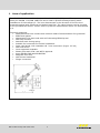
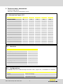
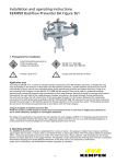
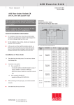
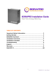
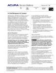
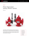
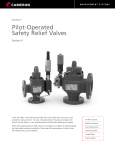
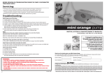
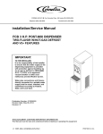
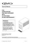
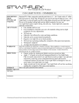
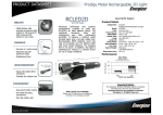
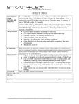
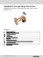
Installation and operating instructions KEMPER Free-flow combined stop and check valve Figure 137 Contents 1 Scope of application .................................................................................... 2 2 Technical data | Dimensions ....................................................................... 3 2.1 2.2 2.3 Dimensions Figure 137 .................................................................................. 3 Materials ..................................................................................................... 3 Configurations ............................................................................................. 3 3 Assembly and installation ........................................................................... 4 4 Operation .................................................................................................... 4 5 Maintenance and repair ............................................................................... 4 5.1 5.2 Function test of the anti-pollution check-valve during maintenance...................... 5 Replacing the stem seal ................................................................................ 5 6 Spare parts and accessories ........................................................................ 6 7 Flow diagram .............................................................................................. 7 EBA combined stop and check valve 1 1 Area of application The KEMPER free flow combined stop and check valve (KRV) Figure 137 is a protection valve EA as per DIN EN 1717/DIN 1988-100 and is used to protect building drinking water installations of fluid category 2. The lines downstream in the direction of flow are thus protected against back pressures and siphon back flow. The valve function can be checked on the provided test device. A drain valve or pressure measurement device can be attached to it. Technical properties: Metal parts that have contact with medium made of dezincification-free gunmetal EPDM seat gasket Maintenance-free stem seal with self-lubricating EPDM lip seal With stop function Stainless steel closing spring Suitable for horizontal and vertical installation Drain vale lateral, with rotatable G ¾" hose connection (Figure 137 02) With test device Cone supported rotatable Plastic parts with KTW- and W270 approval As per DIN EN 13959 and DIN EN 558-1 Stagnant-zone-free With brown handwheel Flange connection EBA combined stop and check valve 2 2 Technical data, dimensions Pressure stage PN 16 Maximum operating temperature 100°C 2.1 Dimensions Figure 137 50 65 80 100 A1 G 3/8 G 3/8 G 3/8 G 3/8 A2 G 3/8 G 3/8 G 3/8 G 3/8 Nominal width DN D1 mm 90 120 120 120 D2 mm 165 185 200 220 D3 mm 102 122 138 158 D4 mm 50 65 80 100 H1 mm 220 293 326 302 L1 mm 230 290 310 350 s1 mm 14 15 16 18 Opening pressure hPa 70 120 140 140 Weight kg 6.32 10.92 13.82 21.6 Max. flow rate (kvs) m³/h 64.7 116 130 186 2.3 2.1 3.8 3.8 Zeta value 2.2 Materials Materials Housing Gunmetal Head part, stem, cone Gunmetal Bonnet seal, stem seal EPDM V-seal EPDM V-nut, washer Rustproof Closing spring Rustproof Test plugs Gunmetal Handwheel Plastic, brown 2.3 Configurations The KEMPER free-flow combined stop and check valve, Figure 137, is available in 2 variants. Figure Number Description 137 01 Without drainage 137 02 Drain valve lateral, with rotatable G 3/4" hose connection and cap EBA combined stop and check valve 3 3 Assembly and installation Thoroughly flush the pipework before installation. The valve can be assembled in either the vertical or horizontal position; during this, be sure to comply with the direction of flow marked on the valve. An easily accessible installation location makes maintenance and inspection easier. Provide a shut-off device in the direction of flow in front of the valve to be able to properly monitor the anti-pollution check-valve. The valve with an upstream stop creates the EA protection unit. To permanently guarantee the flawless functioning of the valve, we recommend installing a drinking water filter as per DIN EN 13443-1 in the direction of flow in front of the valve (e.g., immediately after the water metering equipment). For hygienic reasons, remove the flange guard in front of the valve just before installation. Note: When the supply pressure is applied, before opening the valve make sure that the drain and test device or the drain valve are closed and leakproof. Furthermore, ensure that the drinking water installation in the direction of flow after the valve is checked for leakproofness in accordance with the accepted codes of practice. That prevents water damages caused by unwanted water leaks. 4 Operation The drinking water installation in the direction of flow can be stopped and secured with this valve. Turn the handwheel clockwise to stop; turn counter clockwise to re-pressurise the drinking water installation with drinking water and the full system pressure. During supply, water flows in the direction of flow through the valve and the integrated anti-pollution checkvalve opens. If there is no supply, the anti-pollution check-valve closes through the previously pre-tensioned spring, which prevents the drinking water from backflowing in the opposite direction of flow. Take the pressure loss of the valve into consideration in the piping network calculation. Compliance with Chapter 5, "Maintenance and Repair", is mandatory to maintain the functioning over a long period of time. 5 Maintenance and repair In compliance with the standard on drinking water protection and hygiene regulations, the user/operating organisation is given the following specifications as defaults: Compliant with DIN EN 1717, Section 4.6, regularly scheduled maintenance of the protection unit is required. According to the European-wide defaults of DIN EN 806-5, Table A.1, EA protection units have to be inspected and maintained once annually. Check their proper functioning in regularly scheduled intervals in compliance with the national or regional provisions. Inspect and maintain in compliance with DIN EN 806-5 Appendix B.5. The guaranty is voided in case of malfunctioning of the valve due to pollution. Note: Solely an authorised specialist company is permitted to perform the installation and maintenance. Comply with the guaranty instructions! EBA combined stop and check valve 4 5.1 Function test of the anti-pollution check-valve during maintenance a) The KEMPER outlet-side line must be pressurised and it must be ensured that there is no flow (possibly ensure by closing a downstream valve) b) The valve must not be closed c) Close the stop valve before the anti-pollution check-valve and open the supply side test opening before the antipollution check-valve (see illustration to the right) d) After draining the line, the flow must stop. If it does not stop, check the leak tightness of the stop valve before the anti-pollution check-valve and, if applicable, repair it e) If the flow continues, replace the valve bonnet or the entire valve. 5.2 Replacing the stem seal a) Close the valve and drain on the bonnet side b) Dismantle the handwheel and the gland screw c) Remove the lip seal with a sharp object (e.g. screwdriver); Be careful not to scratch the stem during this d) Carefully push a new lip seal (with valve grease that does not contain mineral oil or with silicon grease) over the stem square and press into the bonnet with the gland screw. Screw the gland screw in at the same time e) Assemble the handwheel and turn back just before the limit stop EBA combined stop and check valve 5 6 Spare parts and accessories Spare part number Designation C91001730304000 Replacement stem seal for DN 50 valves C91001730306500 Replacement stem seal for DN 65, DN 80, DN 100 valves C31001730705000 Replacement bonnet seal for DN 50 valves C31001730706400 Replacement bonnet seal for DN 65 valves C31001730708000 Replacement bonnet seal for DN 80 valves C31001250510000 Replacement bonnet seal for DN 100 valves On request, the entire bonnet can be offered in the respective nominal width Accessory number Designation 410 00 Lap-joint flange for flanged shoulder rings 410 FP 425 00 Flange pair made of lap-joint flange with copper shoulder rings; with seals and rustproof screws Shoulder rings 426 00 Threaded flange PN 10/16 426 FP 427 00 Threaded flange pair PN 10/16; with seals and rustproof screws Blind flange 428 00 Flange seal 429 M Rustproof screws 187 00 Sampling valve J7109 173 00 Drain valve made of gunmetal/plastic EBA combined stop and check valve 6 7 Flow diagram for KEMPER free-flow combined stop and check valve Figure 137, DN 50 K410013700001-00 03/14 We reserve the right to make technical changes Flow rate (m³/h) Contact to manufacturer Gebr. Kemper GmbH & Co. KG Harkortstr. 5 57462 Olpe Germany Phone +49 2761 891-0 Fax +49 2761 891-175 [email protected] www.kemper-olpe.de EBA combined stop and check valve 7