1
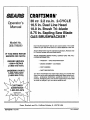
OWNERS MANUAL
SAFETY RULES
&
DANGER
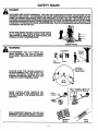
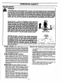
THIS POWER UNIT CAN BE DANGEROUS! THIS UNIT CAN CAUSE SERIOUS INJURY OR BLINDNESS TO THE
OPERATOR AND OTHERS. THE WARNINGS AND SAFETY INSTRUCTIONS IN THIS MANUAL MUST BE FOLLOWED TO PROVIDE REASONABLE SAFETY AND EFFICIENCY INUSING THIS UNIT. THE OPERATOR IS RESPONSIBLE FOR FOLLOWING THE WARNINGS AND INSTRUCTIONS IN THIS MANUAL AND ON THE UNIT. READ
THE ENTIRE OPERATOR'S MANUAL BEFORE ASSEMBEJNG AND USING THIS UNto RESTRICT THE USE OF THIS
POWER UNIT TO PERSONS WHO READ, UNDERSTAr4D AND FOLLOW THE WARNINGS AND INSTRUCTIONS IN
THIS MANUAL AND ON THE UNIT.
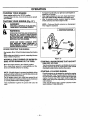
BLADE CAN THRUST VIOLENTLY AWAY FROM MATERIAL IT CANNOT CUT. BLADE THRUST CAN CAUSE
AMPUTATION OF ARMS OR LEGS. KEEP PEOPLE AND
ANIMALS 50 FEET (15 METERS)AWAY.
BLADE THRUST
WARNING
.
i
i
Leg Guards
BLADE/TRIMMER
UNE CAN THRO_; OBJECTS VIOLENTLY, YOU CAN BE BLINDED
OR INJURED. WEAR EYE AND LEG PROTECTION.
Eye
Protection
Boots
HAZARD ZONE FOR THROWN OBJECTS.
BLADE/TRIMMER
LINE CAN THROW OBJECTS
VIOLENTLY.
OTHERS
CAN BE
BLINDED OR INJURED, KEEP PEOPLE AND
ANIMALS 50 FEET (15 METERS) AWAY;
Hazard Zone
Stop Coasting Blade By
Contact With Cut Material.
BLADE COASTS AFTER THROTTLE RELEASE. THE BLADE CAN SERIOUSLY CUT
YOU OR OTHERS.
STOP BLADE WITH CUT
MATERIAL.
Blade
Coasts
®
READ OPERATOR'S MANUAL FOLLOW ALL
WARNINGS AND INSTRUCTIONS. FAILURE
TO DO SO CAN RESULT IN SERIOUS INJURY.
Operator's
Manual
-3-
Safety
Labels
: CONGRATULATIONS on your purchase of a Sears
Craftsmen Brushwacker. It has been designed,
engineered and manufactured to give you the best
possible dependability and performance.
PRODUCT SPECIFICATIONS
cUTrlNG
PATH: ..........
16.5" (Dual Line Head,
ManualAdvance)
Should you experience any problems you cannot easily
remedy, please contact your nearest Sears Service
CenterlDepartment. Sears has.competent, well trained
technicians and the proper tools to service or repair this
unit.
TRIMMER LINE ............
095" Diameter Monofilament
SAPUNG BLADE .........
8 3/4"(225mm), 20 tooth
.78"T'(20mm)
Arbor diameter
BRUSH BLADE ...........
10"(255mm), 3 tooth
.787"(20mm)Arbor diameter
ENGINE: .................
Please read and retain this manual. The instructionswill
-- enable you to assemble and maintain your unit properly.
Always observe the "SAFETY RULES."
36cc, 2-cycle Air Cooled
FUEUOIL MIX RATIO: ........... 40:! (3.2oz_oilper gallon,gas)
IGNITION:................
SolidState
(Air gap.010"-.014")
MODEL NUMBER:
358.798280
IGNITIONTIMING: ........
Non-Adjustable, Fixed
SPARKPLUG TYPE: ......
ChampionCJ-TY
Autolite853
SERIAL NUMBER:
DATE OF PURCHASE:
S_P_,RKPLUG GAP: ........
020"
MUFFLER: ...............
Spark ArrestingScreen
(Requires assembly)
THE MODEL AND SERIAL NUMBER WILL BE FOUND
ON A DECAL ATTACHED TO THE PRODUCT.
YOU SHOULD RECORD BOTH SERIAL NUMBER
AND DATE OF PURCHASE AND KEEP IN A SAFE
PLACE FOR FUTURE REFERENCE.
ENGINE RPM: ............
11,000 RPM Maximum
BLADENUT TORQUE: ....
20-35 lb.-ft.
SHIELD SCREWS: ........
70 lb.-in:Minimum
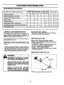
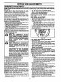
SPECIAL
MAINTENANCE
AGREEMENT
A Sears Maintenance Agreement is available on this
product. Contact your nearast Sears Storafor details
CUSTOMER
=RESPONSIBILITIES
sparkarrestor,maintainedin effectiveworkingorder,orthe enginebeconstructed"
equipped,and maintainedfor:thepreventionoffire. Checkwithyourstate orIomdauthotitlesforreguis.- 'i
ti0ns pertaining to these requirements.. Failureto followthese
requirementsis a violationof the law. The factory provided
spa_ arrest=orscreen is not asesmbledwiththisunit.
._ :.Read and observethe safety rules..
• Follow a regular schedule in maintaining, caring for,
and using your unit:
• Follow
the
instructions
under
=Customer
Responsibilities" and =Storage" sections of this
Operator's Manual.
r
NOTICE
For users on U.S. Forest Land in the states of Caiif0mia, Maine
Oregon, New Jersey, Idaho, Minnesota, and Washington. AI
U.S. Forest Land and the states of California (Public Rseoulces
Codes 4442 and 4443), Oregon, and Washington require, by
law, that certain internal combustionengines operated on forest, brush, and/or grass-covered areas be equipped with a
MANUFACTURED
UNDER ONE OR MOR_ OF THE FOLLOWING pATENTS: 4,974,973;
5,105,'J'7_; D339,591; D333,954.
OTHER U.S, AND FOREIGN PATENTS PEN DING.
, rr
CRAFTSMAN
FULL TWO-YEAR
WARRANTY
GAS-POWERED
BRUSHWACKER
®
ON
BLADED
TRIMMER
For two(2) years from the date of purchase, when this Craftsman Gas-Powered Brushwacker is maintained, lubricated
and tuned-up according to the operating and maintenance instructionsin the owner's manua, Sears will repair, free of
charge, any defect in matedals or workmanship.
This warranty excludes blade nylon line, spark plug, and air t_lter,which are expendable parts and become worn dudng
normal use.
If this Brushwacker is used for commercial purposes, this warranty applies for only 90 days from the date of purchase.
If this Brushwacker is used for rental purposes, this warranty applies for only 30 days frern the date of purchase. This
warranty applies only while this product is in use in the United States.
WARRANTY SERVICE IS AVAILABLE BY RETURNING THE BRUSRWACKER TOTHE NEAREST SEARS SERV|CI
CENTER IN THE UNITED STATES.
This warranty gives you specific legal dghts, and you may also have other rights which vary from state to state.
SEARS, ROEBUCK AND CO., D/817WA, HOFFMAN ESTATES, IL 60179
-4.
=
HARDWARE CONTENTS
Hardware shown full size
Parts bag contents not shown full size
i
Locking Pin
Spark
Arrestor Screen
(4) Screws
(2) Lock
Washers
@
Blade Nut/
Spark Rug
Wrench
(2) Mounting
Screws
J
Carburetor
Hex Key
(2) Nuts
r
i¸
r.....
i --r
i
Screwdriver"
.
i
1
i
I `•.
._• ii1.
Parts packed separately in carton
Line Limiter
3.2 oz. Oil
Metal Blade Shield
Brush Tri-Blade
Plastic Line Xrimmer Shield
with Lthe Umiter Hardware
Shield Support
Plate
Dual Une "Cutting Head
Operator's Manual
O
Shoulder Harness
Handlebar
Sapling Saw Blade
eeLS REQUIRED FOR ASSEMBLY
TO REMOVE BRUSHWACKER FROM
CARTON
Torque Wrench-reference torque values are provided
throughout this manual for tightening hardware.
Phillips Screwdriver
8 mm Wrench
Provided with your Bmshwacker:
Hex Key
Blade Nut/Spark Plug Wrench
Locking Pin
• Remove loose parts included with Brushwacker.
• Remove the loose plastic parts bag from the carton.
• Remove all packing material.
;, Check carton thoroughly for additional loose parts.
-5l
Blade Transport/
Storage Cover
i.i
ASSEMBLY
IF THIS UNIT IS RECEIVED
BLED, REVIEW ALL STEPS IN THIS
SECTION TO BE SURE ASSEMBLY
WARNING:
CORRECT AND
FORTHE OPERATOR.
. Engineer,,/
ThrottleHandle
Screw_
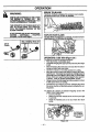
HOW TO ASSEMBLE YOUR
BRUSHWACKER
Mounting'////
8r cket /
DANGER:
Retention
Clip
Figure 2
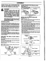
SPARK ARRESTOR
(See Fig. 3 )
SCREEN
ASSEMBLY
.
BARRIER TO KEEP THE OPERATOR'S
Your Brushwackeris shipped with a spark arrestor screen
..FEETFROMB:Ir_._BITHEBLADE_: '.acc_scry.
fyouplantouseyourBrushwaskerinanarea
.
..........
Whe'ma spark arrestor muffler is required by local state, or
.....HANDLEBAR
ASSEMBLY
(See Fig. 1 ) "
"
federal authorities (See =Special Notice" on page 4), pro..............
ceed to nsta as fo owe.
uerore installing me nanolecar,:_you_-musLunmread:the_.
_. _". • "
.........
• thumbscrew
securing the mounting brackets to the Outer
• •.Loosen 4 screws rmm c_lnaer cover wJtnnex Key. He-.
housing,
move cylinder cover.
IMPORTANT: TWO(2) sCREWS
MUFFLER PARTS TOGETHER.
Refer to Figure 15 for proper handlebar Position.
• Place the hand/ebarbetween the upperand lower brackeL The mounting bracket shouldbe between the arrows
on the handlebar. Secure with thumb screw.
• We recommend you adjust the angle of the handlebarfor
best comfort and balance after the unit is assembled.
Figure1
THROTTLE
HANDLE
(See Fig. 2 )
ASSEMBLY
HOLD ALL OF THE
• Loosen 2 screws from muffler screen cover with hex key.
Remove the muffler as an assembly to become familiar
with it's disassembly/reassembly sequence.
• Hold muffler with the screws up.
• Removethe fo!lowing: muffler gasket, mufflerbody, reinforcement plate; baffle plate, and distance pipes.
• Turn over the muffler cover with the screws down.
• Remove 2 screws and raise muffler screen cover.
• Positionspark arrestor screen between the muffler cover
and the muffler screen cover. Align holes and reinsert 2
8cl_ev_s_
"' * Turn over muffler cover with screws up.
• Reinstall in the following Order:. distance pipes, baffle
plate and reinforcement plate. Seat muffler body over
muffler cover and snap them together. Reinstall muffler
gasket.
• Insert 2 screws in cylinder and tighten securely
(60-80 Ib-in).
• Replacethe cylindercover making sure the mufflerguard
interlockswith the crank case assembly. Insert 4 screws,
• and tighten securely.
CylinderCover/MufflerGuard
_X".'_
• Remove the retention screw from the thrott/e hand/e.
• Slide the thrott/e hand/e onto the rightside of the handlebar and align with the screw hole in the handlebar. The
throttle trigger should be facing away from the engine.
• Insert retention screw and tighten with hex key.
• Secure loose cable to handlebar adjacent to mounting
brackets with dip.
_\;.
Cylinder
Reinforcement
Plate
Muffler
Crank
Case
Distance /
B_
Plate
Figure 3
-6-
Muffler
Cover
Spark
Arrestor
Screen
Muffler
Screen
Cover
•
ii
i
ASSEMBLY
iii
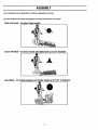
Your brushwacker can be assembled in 3 distinct configurationsas follows:
Go to the sectionforthedesired configuration
and follow the instructions
as provided.
Dual Line Head - for grass & light weeds
Brush Tri-Blade
-for
heavy weeds and light brush up to 1/2" diameter
Saw Blade -for
cutting saplings
and similar media up to 2 1/2" in diameter
-7-
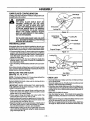
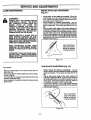
ASSEMBLY
CUTTING LINE HEAD
CONFIGURATION
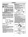
INSTALLING THE PLASTIC
SHIELD (See Fig. 5 )
Brush and Saw Blade ConflguraUonsfollow this section.
• Place the plastic line trimmershieldon the gearbox, and
align the four screw holes as illustmfed.
• Place the shield support plate under the shield and
align the four screw holes.
• Secure the plasticline trimmershieldusing the 4 mounting screws provided in the loose parts bag.
• Tighten evenly (70 Ib-in mimimum) using the hex key
provided in the loose parts bag.
Arbor
_ -F_
&
WARNING:
THE LINE LIMITER IS SHARP AND CAN
CUT YOU. BE SURE TO WEAR GLOVES
WHILE WORKING WITH THE LINE UMITER.
THE PLASTIC UNE TRIMMER SHIELD
MUST BE PROPERLY INSTALLED FOR ALL
LINE TRIMMER USAGE.
THE PLASTIC
UNE TRIMMER SHIELD PROVIDES PARTIAL PROTECTION FROM THE RISK OF
THROWN OBJECTS TO THE OPERATOR
AND OTHERS,
Driyin_] /t!/i_
.....
Di 2! .
INSTALLING UNE :LIMI3_R_-ONTO PI.:ASTIC_?,__;_
Shield
Support __,,
LINE TRIMMER SHIELD (See Fig.4)
Plate
• Pos_on line limiteronto the plastic line trimmershield.
'
--,-,,,,. . / _'___,_,
,,,=_,,_'"::_':rs
_
"///'_
._-_l
Plastic Line _
FdmmerShield
\y_-_-
/
Plast_Une
T,mme,.
Shield
_.
INSTALLING THE DUAL MNE
(See Fig. 6 & 7 )
HEAD
Before installing the dual line head, make sure the driving
diskis in place on the gear box,
• Rotate the hex fastener on the dual line head counterclockwise onto the arbor shaft.
•Tum the arbor shaftto align one of the three holes in the
ddving diskw_ththe hole in the gearbox.
• Insert the locking pin through the gearbox and driving
disk. This will lock the driving disk, and prevent the arbor
shaft from turning while you tighten the dual line head.
• While holdingthe Iockingpinin place, tighten the dual line
head onto the arbor shaft counterclockwise using the
blade nut/spark plug wrench(15-20 Ib-ft);
Should the arbor shaft continue to turnwhile you are tightening the dualline head, re-positionthe/ockingpinthrough.,
the gearbox and driving disk.
Locking Pin
Arbor Shaft
• Secure line limiter to the plastic line trimmershield using
the two mounting screws, lock washers, and nuts found
in the loose parts bag using a phillips screwdriver and
8ram wrench.
• Tighten securely.
Une Umiter
_J_
Figure 5
IMPORTANT: ALTHOUGH SCREW HOLES EXIST ON
BOTH EDGES OF THE PLASTIC LINE TRIMMER
SHIELD, MAKE SURE YOU INSTALL THE LINE UMo
rrER ON THE SIDE SHOWN IN THE ILLUSTRATION.
Nuts_
LINE TRIMMER
.
Line Limiter parts are
located in a bag attashed to the Plastic
Line Trimmer Shield.
Screws
......
Plastic Line
Trimmer Shield
Figure 4
Disk
PRE-INSTALLATION
If the metal blade shield is installed on the unit, you must
first remove the-nut,supportflange, blade, and metalb/ade
shield as follows before installing the plastic fine trimmer
shieldand duat line cutdng head.
• Clip blade transport/storage cover over the blade.
(Refer to figure 9)
• To remove blade (Sea Figures 11 or 14), place lockingpin
through the gearbox and driving disk to preventthe arbor
shaft from turning and remove the blade nut by turning
clockwise with blade nut/spark plug wrench. Save parts
removed for future use.
• Remove 4 screws with hex key holding the metal blade
shield. Save these 4 screws for installationofthe plastic
line trimmer shield.
Dual
Hex Fastener
(underneath)
Figure 6
Lockin! Pir_ual
Plastic Line
Trimmer Shield _'<
II Counterclockwis_
Blade Nut/Sl_ irk Plug
Wrench
Figure 7
-8-
Cutting Head
Remove Clockwis_
,,..
ii
ASSEMBLY
i
|RUSH TRI-BLADE
CONFIGURATION
ii
BLADETRANSPORT/STORAGE COVER
(1See Figure
9 )
e blade transport/storagecover should always be used
when handling either blade.
_utting Line Head configuration is located before this
_-tien; Saw Blade configurationfollows this section.
THE METAL
DANGER:
BLADE SHIELD MUST BE
PROPERLY INSTALLED ON THE UNIT
ANYTIME THE UNIT IS USED WITH THE
BLADE. THE FORWARD TIP ON THE METAL BLADE SHIELD HELPS TO REDUCE
THE OCCURRENCE OF BLADE THRUST
WHICH CAN CAUSE SERIOUS INJURY
SUCH AS AMPUTATION TO THE OPERATOR OR BYSTANDERS.
THE BLADES ARE SHARFAND'CAN
cuT
YOU. BE SURE TO WEARGLOVES WHILE
WORKING WITH BLADES; '"
Saw Blade
J
Blade TrensporVStorag_ Cover
Figure 9
INSTALLING
THE BRUSH "rRI-BLADE
.
10& 11)
.....
NOTE: The bladesin figures 10 &11 are shown without the
blade transport/storage cover for clarity.
RE_;INSTALLATiON
Before installing the brush tri-blade; makesure thedriving ':
diskis in place on the gear box.
the plastic line trimmer shield is installedon the unit, you
ust first remove the dualline cutting headbefore instalIg the blade,,support flange, nut and metal blade shield.
• Place brush tfi-blade onto support flan0e making sure
the hole in the center of the blade is f'rttedaround the
raised center step on the support flange.
:
• Place support flange and blade onto arbor shaft. The
blade should not move from side to side.
• Insert/ocking pin through the gearbox and driw'ngdls_
This will lock the driving diskand prevent the arbor shall
from turning while you tighten the Rut.
• Begin threading the nut (counterclockwise) onto the end
of the arbor shafL
• While holding loctdngp_nin place, tighten the nut onthe
arbor shaft counterclockwise using the blade nut/spark
plug wrench(20-35 Ib-ff).
To remove (See Figure7), place locking pinthrough the
gearbox and driving.'diskt0 prevent the arbor shaft from
tumtng and remove the dual I|ne head by turning c_ockwise with blade nut/spark plug wrench. Save parts removed for future use.
Remove 4 screws with hex key holding the plastic line
trimmer shield. Save these 4 screws for installation of
Ihe metal blade shield.
Fou have already conliguredyour unitfor Saw Blade use,
_u have already installed the metal blade sh=ieldand
rould remove the saw b/adeand go directlyto Installing
e Bnisfi Tri-Blade:
ISTALUNG
lee Fig. 8 )
Metal Blade\Nx.
THE METAL BLADE SHIELD
Sh=eld__:
=lace met'a/blade s_hietdonme gearbo_cand_alignfour
_crew holes.
:_lacethe shield support plate L]ndeT.the_blade gua-_l
3rodalign the four,screw holes.
_ecure the metal blade shield using the 4 mounting
screws provided.
ghten evenly (70 Ib-in minimum) using hex key proded in loose parts bag.
Arbor
Shield Support
Locking Pin
Arbor Shaft'-_'--_
_:
_"
7_.,=-.-Driving Disk
Brush Tri-Blade
Support_e._--Flanqe
Nut
Figure 10
Locking Pin
Brush Tri-Blade
,_
Co_lockwise
_,_ __'_
_
_'Remove Clockwise
Metal Blade Blede N_'ut/Sp'_rk
Plug
Metal
Driving
Disk
Shield
Shield
Rgure 8
Wrench
Figure 11
-9-
ASSEMBLY
SAW BLADE CONFIGURATION
,SawBlade
Cutting Une Head and Brash Tri-Blade configurationsare
located before this section.
THE METAL
DANGER:
BLADE SHIELD MUST BE
PROPERLY INSTALLED ON THE UNIT
ANYTIME THE UNIT IS USED WITH THE
BLADE. THE FORWARD, TIP ON THE METAL BLADE SHIELD HELPS TO REDUCE
TIlE OCCURRENCE OF BLADE THRUST
WHICH CAN CAUSE SERIOUS INJURY
SUCH AS AMPUTATION TO THE OPERATOR OR BYSTANDERS.
Driving Disk
Locking Pin
Fiqure 12
Metal Blade
=gPin
THE
AND C=AN:CUT
YOU.BLADESAR_SNARP
BE SURE_TO;WEAR_GLOVE_WHIIJE
WORKING WITH BL_4DES. "_
'
i
PRE-INSTALLATION
Saw Blade
If the plastic line trimmershield is installed on the unit,you
must first remove the dual line cutting head before installing the blade, supportflange, nut and metal blade shield.
• To remove (See Figure-7), place locking pin throughthe
gearbox and ddving disk to prevent the arbor shaft from
turning and remove the dual line head by turning clockwise with blade nut/spark plug wrench. Save parts removed for future use.
• Remove 4 screws with hex key holding the plastic line
trimmer shield. Save these 4 screws for installationof
the metal blade shield.
• Go to =Installing The Metal Blade Shield" befo reproceeding.
If you have already configured your unit for brush tri-blade
use, you have already installedthe metai blade shield and
should remove the brush fri-blade.
INSTALUNG THE SAW BLADE
(See Fig. 12,13,
& 14 )
Driving
Support Flange -_'1"__"=-'-
Nut
Figure 13
Metal Blade __
Shield
Install Counterclockwise
Blaoe
N.V
Saw Blade
=
Figure 14
NOTE: The blades inf gul:esl:2-_1:_4areshownwithout the _ • CHECK LIST
blade transport/storage cover for clarity.
• Check all fasteners. Make sure they are tight and there
Before installingthe blade, make surethe driving;diskis'm :, are no loose parts.
place on the gear box.
• Check to make sure the Throttle Cableis positionedand
clippedto the Brushcutter handlebar.
IMPORTANT: WHEN INSTALLING THE SAW BLADE,
• Check the Line Limiter. Make sure the Line Umferis corTHE ARROW ON BLADE SHOULD POINT iN THE
rectly fastened to the plastic line trimmersh_eld, with the
DIRECTION INDICATED.
long leg of the Une Limiterpointing toward the_center of
• Place saw blade onto support flange making sure the
the shield.
hole in the center of the blade is fitted around the raised
• Make sure the blade is secure.
center step on the support flange.
• Turn the blade by hand. If the blade binds against the
• Place support flange and blade onto arbor shaft. The
shield or wobbles, the blade is not centered. Reinstall the
blade should not move from side to side.
blade.
• Insert locking pin through the gearbox and driving distc
• Make sure the long arm of the handlebar extends to the
This will lock the drivfng disk and prevent the arbor shaft
left of the tube and in front of the operator.
from turning white you tighten the nut.
• With the unit supported by its harness strap, adjust han• Begin threading the nutcountere!ockwise ontothe end of "
dle angle for best comfort and balance before first use.
the arbor shaft, which is a left-hand thread. To tighten,
turn counterclockwise;to loosen, turn clockwise.
• While holding locldng pin in place, tighten the nuton the
arbor shaft counterclockwise using the blade nut/spark
plug wrench(20-35 Ib-ft).
- 10-
iiiiii
OPERATION
IIIII
KNOW YOUR BRUSHWACKER (See Fig. 15 )
READ THIS OPERATOR'S MANUAL AND SAFETY RULES BEFORE OPERATING YOUR BRUSHWACKER. Compare
the illustrations with your unit to familiarize yourself with the location of the vadous controls and adjustments. Save this
manual for future reference.
AIR FILTER._..._.I_
_
(BackSide)
(INSIDE)
_.,_j {_
v \
SPARKPLUG
(INSIDE)
CHO_:_'V_
I\1
/
MUFFLER &
STARTER ROPE
THROTTLE HANDLE
THROTTLE LOCKOUT
ENGINE SWITCH 0
THRO'I-rLE TRIGGER
HANDLEBAR
TUBE
PLASTIC LINE
TRIMMER SHIELD
METAL BLADE :
J?oI %
SHIELD
\
SHIELD
BRUSH TRI BLADE
DUAL UNE HEAD
CUTTING LINE HEAD
CONFIGURATION
BRUSH BLADE
CONRGURATION
_
SAPLING SAW BLADE
SAW BLADE
CONRGURATION
i
Figure 15
The ENGINE SWITCH has a stop position.
The THRO'I-rLE TRIGGER controls engine speed.
The STARTER ROPE HANDLE is used for starting the
engine.
The DUAL LINE CUTTING HEAD is designed to c_Jtgrass
and light weeds.
The CHOKE LEVER provides additional fuel to the engine
when starting a cold engine.
The BRUSH TRI-BLADE is designed to cut grass, weeds,
and brushy vineS up to 1/2 inch m diameter.
The THROTTLE LOCKOUT prevents the THRO'I-FLE
TRIGGER from being squeezed accidentally.
The SAW BLADE is designed to cut grass, weeds, and
woody brush and small trees up to 21/2 inches in diameter.
- 11 -
i
i
OPERATION
i
STOPPING
•
•
ENGINE
Move engine switch to the =STOP" position.
If engine does not stop, move the choke lever upward
(Full Choke).
SHOULDER
_
•
YOUR
HARNESS
(Fig.
16 )
BLADE TRANSPORT/STORAGE
(Fig. 17 )
•
•
COVER
Turn off the engine before installingthe blade transport/
storage cover over the blades.
AttachthebladetransporVstoragecoverovertheblade,
which may be or_or off of the unit.
Brush Tri-Blade
Saw Blade
WHEN WORKING WITH A BRUsHWACKER
IT SHOULD ALWAYS BE HOOKED TO A
SHOULDER HARNESS. IF NOT, YOU CANNOT
CONTROL THE BRUSHWACKER
WARNING:
SAFELY WHICH CAN CAUSE INJURY TO
YOURSELF OR OTHERS.
Place harness on the shoulders with the latch on the
chest, the Danger Sign on,theback;,andthe_ook.on:the;_:
dght thigh..The
h0ok::ShOul_
above your knee, or 6"(15cm)
•
Figure 17
Attach hook through one ofthe;susperJsion.holes.on.the
..,;i_._,_--.. __. .. ........
;
outer housing and adjust:the sbaulde_ hamessfor bal- • •HANDLEBAR
ADau_ I MJ-Nt (t-tgure ]u )
ance so the blade or dual lihe head is level with the
• Turn the engine off before adjusting handlebar.
ground.
• Put on shoulder harness and hook on the unit.
Tension the side belts so that the weightis evenly distdl_
• Adjust the handlebar by slightly unthreading the thumb
uted across your shoulders.
A pmpedy adjusted
screw and rotatingthe handlebar forward or backward.
shoulder strap will support the entire weight of the unit,
freeing your arms and hands to guide and control the
Ensure the mounting brackets remains beWeen the arrows on the handlebar.
cutting motion.
Tighten the thumb screw before starting the engine,
Mounting Brackets -..-.-_
Figure 18
THROTTLE TRIGGER & LOCKOUT
(Fig. 19 )
Hook
Suspension
Hole
•
The throttle tdggercontrols engine speed. At idle, a centrifugal clutch automatically disengages the blade/dual
line head from the engine. The blade/dual line head will
coast to a stop.
• The throttle lockout must be depressed before the
throttle tdgger can be depressed. Also, the throttle lockout prevents unintentional activation of the throttle trigger.
Throttle Lockout
\
Figure 16
Throttle Trigger
Figure 19
- 12-
i
OPERATION-SAFETY
i
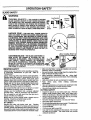
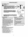
3LADE SAFETY
WARNING
THROWN
OBJECTSTHE RAPIDLY MOVING
BLADE CAUSES OBJECTS TO BE THROWN VIOLENTLY.
THE SHIELD WILL NOT PROVIDE COMPLETE PROTECTION TO THE OPERATOR OR OTHERS.THE OPERATOR
MUST WEAR A SAFETY FACE SHIELD OR GOGGLES.
ALWAYS WEAR SAFETY LEG GUARDS AND BOOTS.
KEEP OTHERS AT LEAST 50 FEET (15 METERS) AWAY.
Leg Guards
\
Face
Shield
Thrown
Objects
II
Boots
HAZARD
ZONE
- THIS UNIT WILL THROW OBJECTS
AND CUT. KEEP OTHERS INCLUDING CHILDREN, ANI. MALS, BYSTANDERS, AND HELPERS ATLEAST 50 FE_ I
(15 METERS) AWAY I_B_)M_:THE!;OBERATOR_ND_,UN_ _
STOP THE ENGINE AND;BLADE IMMEDIATELY IFYOU.ARE._,
APPROACHED. IN AREAS-.WHERE::OTHER:PEOPLE AND_
ANIMALS ARE PRESENT,_.SUGH:AS_NEAR;SIDEWA[,.KS,i:
• STREETS, HOUSES, ETC., ITIS STRONGLY RECOMMEND.:
ED THAT THE OPERATOR USE THE BUDDY SYSTEM;THAT
IS, HAVE ANOTHER PERSON SERVE AS A '_LOOK OUT,"
KEEPING HIMSELF AND OTHERS AT LEAST 50 FEET (15
METERS) AWAY FROMTHE OPERATOR.
100 Foot
COASTING BLADE- THEBLADECONTINUES
TO
SPIN AFTER THE ENGINE IS STOPPED OR THE
__
THROTTLE IS RELEASED. THE COASTING BLADE
Blade'_.._
CAN THRUST, THROW OBJECTS, OR SERIOUSLY
Coasts F
CUT-YOU IF ACC DENTALLY TOUCHED. STOP THE
//
BLADE BY LEAVING IT IN CONTACT WITH MATERIAL._
ALREADY CUT. USETHE 9OCLOCK"POSITIONAS_.
THE POINT OF CONTACT.
PERATOR
SAFETY
•
i Stop
Blade
Make sure the blade is Prol_edy installed and securely
fastened. Referto'Assembly."
Always wear eye protection when operating, servicing,
or performing, maintenance on your unit. Refer to ' ° Besuretheblade_stopstumingwhentheeng
ineidles;:'"
=Accessories.
Refer to'Trouble Shooting Chart."
Al_,.
wear onn n_nts onn s eeve_boots_and _oves, ,-" Make carburetor adjustments with the drive shaft,
Wearino safety leg auards Is recommended,'Do_not_uo......... housing,supportedto prevent the blade from contacting
barefoot or wear sandals, jewelry, short pants, sh6rt :
anyobject.
,sleeves. Being fully covered helps to protect you from, • Holdunit by hand; do not use harness for support.
_pEiecesof toxic p!ants thrownby_.e 101adeor
cuttit_ghead.
• Keep • others •away when
making
carburetor
_ecuro nair so _ is above ShOUlderlengzn._ecure loose
adjustments.
clothing, or clothingwith loosely hanginglies, straps,tas- • Have all maintenance and serv ce not exp ained n th s
sale, etc,•"they canbe caught =nmowng parts j Center.
manual performed by a Seam Serv'ce
Do not operate this unit when you are tired, ill, or under
Use only Sears blades and accessodes.
the influence of alcohol, drugs, or medication.
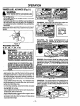
cUTnNG
SAFETY
Always use the handlebar and a properly adjusted
•
Inspect
the
area to be cut before each use. Remove
shoulder strap. Refer to "Assembly" and "Operation".
objects (rocks, broken glass, nails, wire, string, ,etc.)
Do not swing the unit with such force that you are in
which can be thrown Orbecome entangled in the blade.
danger of losing your balance.
• Always keep the engine on the right side of your body.
Never start or run the engine inside a closed room or
Hold the unit firmly with beth hands.
building. Breathing exhaust fumes can kill.
Keep firm footingand balance. Do not over-reach.
Keep handles free of oil and fuel.
• Keep blade below waist level.
liT SAFETY
• DonotraisetheengineabeveyourwaisL
Thebladecan
Inspect the entire unit before each use. Replace
come dangerously close to you[ body.
damaged parts. Check for fuel leaks and make sure all
• Cut at full throttle.
handles, guards, and fasteners are in place and secure.
Cut from your right to your left.
Be sure the metal blade shield is properly attached. The
•
Use only for jobs explained in this manual. Do not use
metal blade shield must be installed for all blade usage.
the blade as an edger. The shield does not provide
adequate protection.
- 13-
OPERATION-SAFETY
m ii
BLADE SAFETY
DANGER
THIS POWER UNIT CAN BE DANGEROUS! THIS UNIT CAN CAUSE SERIOUS INJURY OR BLINDNES;
TO THE OPERATOR AND OTHERS. THE WARNINGS AND SAFETY INSTRUCTIONS IN THIS MANUAL
MUST BE FOLLOWED TO PROVIDE REASONABLE SAFETY AND EFFICIENCY IN USING THIS UNTO.
THE OPERATOR IS RESPONSIBLE FOR FOLLOWING THE WARNINGS AND INSTRUCTIONS IN THIS
MANUAL AND ON THE UNI_. READ THE ENTIRE OPERATOR'S MANUAL BEFORE ASSEMBLING AND
USING THIS UNIT! RESTRICT THE USE OF THIS POWER UNIT TO PERSONS WHO READ, UNDERSTAND AND FOLLOW THE WARNINGS AND INSTRUCTIONS IN THIS MANUAL AND ON THE UNIT.
BLADE THRUST - WHEN THE SPINNING BLADE CONTACTS
ANYTHING IT CANNOT CUT, A DANGEROUS REACTION MAY
OCCUR CAUSING THE ENTIRE UNIT AND OPERATOR TO BE
THRUST VJOLENTL_IN AN_DIRE_TION;
T_IIS_,RF_.A,
CTiON IS _i
CALLED BLADE 7T.4BUST;FASi:A
RESULT,_T/-JE/O_R
CAN
LOSE CONTROL ,OF:THE_UNIT.:_USE HANDLEBAR;_SHOULDER
-i
HARNESS; :AND KEEPoMETAIJ'BI_ADE SHIEED INF:
PE_CE. •MAKE
SURE OTHERS ABE_A_÷JLEAST SO,_FEEF[_(15iMETERS) AWAY.
KEEP BLADE SHARR CUT AT FULL THROTTZE AND FROM
_;
YOUR RIGHT TO LEFT.. KEEP HANDS, FEET AND UNIT IN PROPER POSITION; REFER TO "GUARD AGAINST BLADE THRUST."
BLADE THRUST
ARBOR
PROPER
BLADE-
USE ONLY THE 8 3/4 INCH SAW BLADE
OR 10 INCH BRUSH TRI-BLADE AND PROPER HARDWARE
AS SHOWN. THE USE OF ANY OTHER PARTS CAN RESULT
IN SERIOUS INJURY. DO NOT USE ANY ACCESSORY OR
ATTACHMENT OTHER THAN THOSE RECOMMENDED BY THE
MANUFACTURER FOR USE WITH THIS UNIT. BLADES THAT
ARE BENT, WARPED, CRACKED, BROKEN, OR DAMAGED
CAN FLY APART AND CAUSE SERIOUS INJURY. DO NOT
USE; THROW AWAY.
•BLADE
THRUST
8 3/4" Saw Blade
IS a reactionthat only occurs REDUCE THE CHANCE
when using a bladed unit. This reaction can cause
serious injury such as amputation. Carefully study
this sectlon. It is importantthat you understand what
causes blade thrus_ how you can reduce the chance
of It occurring; and how you can remain in:controlof
the unit if blade thrustcocurs.
WHAT CAUSES
OPENING
.787"
BLADE
THRUST?
Blade Thrustcan ocourwhen the spinning blade_€on_
tacts an object that it does not cut. This contact
causes the blade to stop for an instantand then suddenly move or =thrust" away from the object that was
hit. The "thrusting" reaction can be violent enough to
cause the operator to be propelled in any direction
and lose control of the unit. The uncontrolled unit can
cause serious injury if the blade contacts the operator or others.
WHEN DOES BLADE THRUST
OCCUR?
Blade thrust can occur without warning if the blade
snags, stalls, or binds. This is more liketyto occur in
areas where it is difficult to see the material being cut.
By using the unit properly, the occurrence of blade
thrust will be reduced and the operator will be less
likely to lose control.
The forward tip on the metal blade shield helps to reduce .the occurrence of blade thrust but cannot prevent the occurrence. The operator must follow all
warnings and safety instructions in this manual to
lessen the chance of blade thrust ocourdng and to
maintain control of unit ifthe reaction does occur.
- 14-
.\
_ "i
I
-tO"Brush Td-BISdE
OFBLADETHRUS'r
Cut vegetation up to 2 1/2" diameter saplings with
saw blade.
• Cutonlygrass, weeds, andwoedybrushuptol!2"
in
diameter with the brush t fi-bisde:Do:nottet theblade
contact matedal it cannot cut such as stumps, rocks,
. fences, metal, etc., or clusters of hard, woody brush
having a diameter graater than 2 1/2 inches.
Keep the blade sharp. A dull blade is more likely to
snag and thrust.
• Cut only at full throttle. The blade has maximum cutting power at full throttle and is less likely to bind or
stall.
=Feed" the blade deliberately and nottoo rapidly. The
blade can thrust away if it is fed too rapidly.
Cut only from your fight to your teft.
i
ill
OPERATION
ill
WARNING:
BRUSH TRI-BLADE:
The Brush Td-Blade isdesigned to cut grass, heavy weeds,
) to 1/2 inch in diameter.
THE BLADE CONTINUES TO SPIN AFTER
THE ENGINE IS TURNED OFR
THE
COASTIN_I BLADE CAN SERIOUSLY CUT
YOU iF ACCIDENTALLY TOUCHED.
THE OPERATOR OR OTHERS MUST NOT
TRY TO CLEAR AWAY CUT MATERIAL
WiTH THE ENGINE RUNNING OR THE
BLADE TURNING.
STOP ENGINE AND BLADE BEFORE REMOVING
MATERIALS
WRAPPED
AROUND THE BLADE SHAFT.
SAPLING
SAW BLADE:
brush and
Blade
Coasts
®
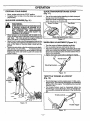
OPERATING
/ USE TIPS (Figure 20 )
To establish a rhythmic cutting procedure:
• Plant feet firmly, comfortably apart.
• Cut while swinging the upper part of your body from dght
to left.
Move forward to the next area to be cut after the return
swing and plant feet once more.
• Use the 8 o'clock to 10 o'clock position for cutting.
• Bringthe engine to full throttle before entering the materialto be cut. The blade has maximum cutting power at
fullthrottle end is less likelyto bind, stall, or cause blade
thrust, which can result in serious injuryto the operator
or others. Refer to =Guard Against Blade ThrustS; ....
• Alwaysreleasethrottletriggerandallowenginetoretum
to idle speed when not cutting.
• Cut only from your right to your left. Swinging the unit in
the same direction as the blade spins increases the cutting action.
To reduce the chance of material wrapping around the
blade, follow these steps:
• Cut at full throttle.
• Swing the unit into material to be cut from your right
to your left.
• Avoid the material just cut as you make the return
swing.
Figure 20
- 15-
OPERATION-SAFETY
ii,¸
LINE TRIMMER
&
.
i
i
SAFETY
WARNING:
THE RAPIDLY
MOVING LINE CAUSES OBJECTS TO
BE THROWN VIOLENTLY. THE PLASTIC LINE TRIMMER SHIELD WILL NOT PROVIDE COMPLETE PROTECTION TO THE OPERATOR OR OTHERS. THE
OPERATOR MUST WEAR A SAFETY FACE SHIELD
OR GOGGLES. ALWAYS WEAR HEAVY, LONG PANTS
AND BOOTS.KEEP OTHERS AT LEAST 50 FEET (15
METERS) AWAY.
Leg Guards
P
[#\
\
Face
Shield
mm
Boots
h
_lo0Foot
/
THIS UNIT WILL THROW OBJECTS AND CUT. KEEP OTHERS INCLUDING CHILDREN, ANIMALS, BYSTANDERS
AND HELPERS Al_:LE_ST;_SO_iFEE_(15"METERS}:_AWAY
FROM THE OPERATOR_;AND:_TOO/_.'STOF_E_ENGINE
IF
YOU ARE APPROACHED.
_.
..
_
(30 meters)
Hazard Zone
Manual Advance Dual Une Head
DUAL LINE HEAD PARTS THAT ARE CHIPPED_ CRACKED OR
DAMAGED IN ANY OTHER WAY CAN FLY APART AND CAUSE
SERIOUS INJURY. DO NOT USE, REPLACE DAMAGED PARTS
BEFORE USING THE UNIT.
)PERATOR
•
•
•
•
•
•
UNIT S .FE'W
SAFETY
Always wear eye protection when operating, servicing,
•
or performing maintenance on your unit. Refer to =AcP_,easories."
Do not operate this tool when you are tired, ill or under
the influence Of alcohol, drugs, or medication.
Always wear long pants long sleeves boots and gloves.
Wearing safety leg guards is recommended. Do not go
barefoot or wear sandals, jewelry, short pants, short
•
sleeves. Being felly covered helps to protect you from
p,p
i_es_toxicp!_tsthrownbythebladeorcuttinghead.
•
_ecure hair so n _sacove snou_eerlengtn. _ecure loose
cl "'in o I ..............................
._nt_;t_cl°c_nn_e%/_h_e_mn_a_g_ngoa_tes'_raps'tas:
•
_
.-,-: y .....
,,u ..
9_
,
uo not swing me too=wim_eucn,tor_ethatyou are,indan- t -ing
ger of Iostag your .b_J.
ance.
.....
°
J_ever star[ or run _ne englne_IBSIQ_a'L,"IOSoo;
room,:or :
h,,..,.,.
^_,._.._,_e_,_h;_n_,l_s_,r;,eUo;_,=an
__..,,.,_^
_ f=umeecan kill.
P
IlU fU_I.
CUTTING
•
SAFETY
Inspect the area to be cut before each use. Remove objects
(rooks, broken glass, nails, wire, string, etc.) which can be
thrown or become entangled in the dual line head.
• Always use the shoulder harness.
• Always keep the engine on the right side of your body.
• Hold the tool firmly with both hands.
• Keep firm footing and balance. Do not over-reach.
• Keep the tdmmer head below waist level.
• Do not raise the engine above yourwaist.
• Keep all parts of your body away from the dual line head
and muffler when engine is running.
• Use only for jobs explained in this manual
- 16-
Use Only Good Quality
Replacement Parts
Inspect the entire unit before each use. Replace damaged parts. Check for fuel leaks and make sure all fas*
toners are in place and securely fastened.
Use only .095" diameter good quality monotilament line.
Never use wire or rope, string, etc.
Be sure the plastic line tdmmer shield is properly attached.
"
. ,
Make sure dual ne head s properly installed and eecurely fastened. Refer to =Assembly"
Be sure dual line head,stops tuming _then engine idles_
R_-fer to =Carh_m.tnrAdlu_tm_.nt_"
"............
Makecarburetoredjustmentswiththedriveshaffhousingsupportedtopreiienttheduallineheadfmmcon-tactany object.
Keep others away when making carburetor adjust.
me_ts
Use only good quality accessories or attachments
i
OPERATION
:UMMER LINE ADVANCE (Fig. 21 )
WARNING:
STOP ENGINE BEFORE
ADVANCING LINE.
"rum off the engine.
Unhook the unit from the shoulder harness and put the
unit on the ground.
Push blue lock button in on dual line head with left hand
and pull one line out with right hand. As line begins to
exit, release lock buttonand pu!lboth linesuntildual line
head locks.
Pretract excess line, push lock button in on dual line head
lfi left hand and turn blue dng on dual line head counter_ckwise.
Figure 22
TRIMMING - Allow onlythe tip of the line to make contact. Do not force trimmer line into work area.
REMEMBER
Keep dual itne
head 3 inches
above
the
ground while
trimming.
TRIMMING
Figure 23
•
Figure 21
SCALPING - The scalping technique removes unwanted vegetation. Allow the tip of the line to strike
ground around trees, posts, monurnents, etc. Thistechnique increases line wear.
PERATING ! USE TIPS
tg. 22 , 23 , 24 , 25 , & 26 )
&
W .RNING:
USE MINIMUM SPEED AND DO NOT
CROWD THE LINE WHEN CUTTING
AROUND HARD OBJECTS (ROCK, GRAVEL, FENCE POSTS, ETC), WHICH CAN
DAMAGE THE DUAL LINE HEAD_ BE,
COME ENTANGLED IN TPIE LINE, OR BE
THROWN CAUSING A SERIOUS HAZARD.
Figure 24
MOWING - Your trimmer is ideal for mowing in places
conventional lawn mowers cannot reach. Keep the line
parallel to the ground. To avoid scalping the ground and
damaging the unit, do not press dual line head into
ground.
ALWAYS WEAR EYE PROTECTION. NEVER LEAN OVER THE DUAL LINE HEAD_
ROCKS OR DEBRIS CAN RICQGHET, OR
BE THROWN II
INJURY.
•The line will easily•removegrass and weeds from around
walls;fences, trees, and flower beds; but it also can cut
the tender bark of trees or shrubs and sear fences, To
help avoid damage especially to delicate vegetation or
trees with tender bark, shorten lineto 4-5 inchesand use
at partial throttle.
The tip of the line does the cutting. You will achieve the
best performance and minimum line wear by not crowding the line into cutting area.
For tdmrning or scalping, use partial throttle to increase
line life, especially:
- during light duty cutting.
- near objects around which the line can wrap such as
small posts, trees or fence wire.
Always release throttle triggerand allow engine to return
to idle speed when not cutting.
Hold bottom of the dual line head about 3 inches above
ground and at an angle.
MOWING
Figure 25
•
- 17-
SWEEPING-The fanning action of the rotating line can
be used for a quickand easy clean up. Keep the line parallel to and above surfaces being swept and move unit
from side to side.
Figure 26
OPERATION
==
BEFORE STARTING ENGINE:
BE SURE TO READ THE FUEL SAFETY
WARNING:
INFORMATION
IN.THE SAFETY RULES
SECTION ON PAGE 2 OF THIS MANUAL
BEFORE YOU BEGIN.
IF YOU DO NOT UNDERSTAND THE FUEL
SAFETY SECTION DO NOT ATTEMPT TO
2-CYCLE OIL:
CRAFTSMAN 40:1 2 cycle oil is strongly recommended.
This oil isspeciallyblended with fuel stabilizersfor increased
fuel stability (extends fuel life up to 5 times longer) and
reduced smoke.
If CRAFTSMAN 2 cycle oil is not available, use a good
quality 2 cycle AIR-COOLED engine oil that has a
recommended fuel mix 40:1.
FUEL YOUR UNIT; SEEK HELP FROM I
SOMEONE THAT DOES UNDERSTAND THE I
IMPORTANT!- Do not use:
FUEL
SAFETYASSISTANCE
SECTION OR-CALL
CUSTOMER
HOTLINE THE
AT
1-800-235-5878,
GASOLINE
The two_-cycleengine on this product requiresa fuel mixture
of regular unleaded gasoline and a high quality 2-cycle erigine oil (AIR-COOLED) for lubrication of the bearings and
other moving pads. The correctfuel/oil m_um is 40:1 [see
Fuel Mixture Chart). Too little oil or the incorrect oil type will
cause poor performance and may cause the engine to overheat and seize.
Gasoline and oil must be premixed in a clean approved fuel
container. Always use fresh regular unleaded gasoline.
•
AUTOMOTIVE OIL
•
BOATOILS (NMMA. BIA. etc.)
These oilsdo not have proper additivesfor2-cyole, AIRCOOLED engines and can cause engine damage.
GASOLINE
AND OIL MIXTURE
Mix gasoline and oil as follows:
•
This engine has been certified to operate on unleaded
gasoline.
Consult chart for correct quantities.
Do not mix gasoline and oil directly in the fuel tank.
FOR ONE GALLON:
Pour 3.2 ounces of high quality, 2--cycle engine oil
into an empty, approved one gallon gasoline container.
IMPORTANT:
Experience indicates that alcohol
blended fuels called gasohol (or using ethanol or methanol) can attract moisture, Which leads to oil/gas separation and formation of acids during storage. Acidic gas
can damage the fuel system of an engine while in storage. To avoid engine problems, the fuel system should
be emptied before storage for30 days:or longer. -Drein
the gas tank, then run the fuel.out.of the carburetor.and
fuel lines by starting the engineand letting it.run until it
stops. Use fresh fuel next season... See:,.STORAGE
instructions for additional information. Never use engine
or carburetor cleaner products in the fuel tank or permanent damage may occur.
Add one gallon of regular unleaded gasoline to the
gallon container, then securely replace the cap.
Shake the container momentarily.
The mixture is now ready for use. Fuel stabilizer can
be added at thistime if desired; follow mixing instruotions on the label.
FUEL MIXTURE CHART
FUEL STABILIZER
40:1 FuehOil Mix Ratio
Fuel stabilizer is an acceptable alternative in minimizing the
formation of fuel gum deposits during storage. Add stabilizer
to gasoline in fuel tank or storage container. Always follow
the fuel mix ratio found on the stabilizer container. Run
engine at least 5 minutes after adding stabilizer to allow the
stabilizer to reach the carburetor. You do not have to drain
the fuel tank for storage if you are using fuel stabilizer.
CRAFTSMAN 40:1 2 cycle engine oil is specially blended
with fuel stabilizers. If you do not use this Sears oil, you can
add a fuel stabilizer (such as Craftsman No. 33500) to your
fuel tank.
- 18
Gasoline
1 gallon
3,2
1.25 gallons
4.0
2.5 gallons
8.0
NOTE: One gallon fuel containers will hold more than one
gallon. If too much gasoline is in the container,the resulting
gas-to-oil fuel mixture will not be correct for proper engine
operation.
-
OPERATION
,
;TOPPING YOUR ENGINE
Move engine switch to the "STOP" position.
If engine does not stop, move the choke lever upward
(Full Choke).
TARTING YOUR ENGINE (Fig. 27 )
NOTE: Choke and throttle advance are disengaged
when tdggel'is squeezed.
THE DUAL LINE HEAD OR BLADE WILL
DANGER:
TURN WHEN THE ENGINE STARTS.
_
i
Pull starter handle with your right hand until engine attempts to run or pops.
After engine attempts to run, turn choke lever downward end repeat starting attempts untilengine runs.
After 10 seconds running, squeeze trigger to release
thrott/eadvance and return engine to idle.
STARTING POSITION
WARNING:
.I
BELS ON THE
BEFORE STARTING ENGINE.
AVOID ANY BODILY.CONTACT. WITH
THE MUFFLER WHEN STARTING
=.FORE STARTING
THE ENGINE:
Fuel engine. Move 10feet (3 meters) away from fueling
site.
Rest engine and shield on ground, supporting tdmmer
head or blade off ground.
Figure 27
_.RTING A COLD ENGINE OR WARM ENGINE AFTER RUNNING OUT OF FUEL:
STARTING A WARM ENGINE THAT HAS NOT
Move the engine switch to the =START" position.
Turn choke lever upward to automatically set the
choke and throttle advance for starting.
RUN OUT OF FUEL
Turn the choke leverupward to set throttle advance for
starting and then return the choke leverto the normal
downward position before starting the engine.
MOTE: If throttle tdgger is squeezed accidently dudng
starting, it will be necessary to reset throftleadvance by
turning the choke lever back up.
For hot engine restart, turn choke lever upwardto set
_hrottleadvance forstading andthenretumchokelever.
_onormal position before starting engine_
-told brushwacker
land.
STARTING A FLOODED ENGINE:
against the ground with your left
- 19-
Flooded engines can be started by moving the engine
switch fromthe "STOP" positionand the choke lever in
the =OffChoke"position; then pull the rope to ctear the
engine of excess fuel. This could require pulling the
starter rope many times depending on how badly the
unit is flooded.
If the unit still doesn't start, call the Customer Assistance Hotline at 1-800-235-5878.
I
'
RESPONSIBI LITIES
CUSTOMER
i
MAINTENANCE
i
ii
SCHEDULE
i
Fill in dates as you complete regular service
After
Use
Before
Use
Every Every
5 hrs. 10 hrs.
Every Every
25 hrs. Season
Sewice Dates
Clean unit and labels.
/J
Check for damaged or worn parts.
Check for loose fasteners and parts.
Clean Air Filter
Rep!ace Spark Plug
/!
Inspect Muffler (Sewice if necessary)
p-
Clean/Replace Spark Arrestor Screen (if installed)
Check Gearbox Lube
i1.1
ii
i
i¸
,.
•
GENERAL
i
i¸ ,
.....
i
RECOMMENDATIONS
i
•
• i
_,.
•
,i
CLEAN UNIT AND LABELS
The warranty on this unit does not cover items that have
been subjected to operator abuse or negligence. To
receive full value from the warranty, the operator must
maintain unit as instructed in this manual.
Some adjustments will need to be made periodically to
properly maintain your unit.
Aft adjustments in the =Service and AdjustmentS"section
of this manual should be checked at least once each
season.
• Once a year, replace the spark plug, replace air filterelement and check blades for wear. A new spark plug and a
clean/new air filter element assures proper air-fuel mixture and helps your engine run better and last longer.
* Follow the maintenance schedule in this manual.
- Clean the unit using a damp cloth with a mild detergenL
Wipe off the unit with a clean dry cloth.
BEFORE EACH USE
CHECK FOR DAMAGED/WORN
• Blades-
PARTS
replace blades that are bent, warped, cracked,
• or damaged in any way.
Dual line head - replace trimmer head pads that are
bent, warped, cracked, or damaged in any way.
• Fuel cap - replace broken or eak ng fue cap.
• Gearbox- replace a cracked gearbox.
• Shields - replace shields that are bent, warped, cracked,
or damaged in any way.
LUBRICATION
_
_l
CHART (Fig.
28 )
WARNING
DISCONNECT
THE SPARK PLUG BEFORE
PERFORMING
MAINTENANCE
EXCEPT
FOR CARBURETOR ADJUSTMENTS.
Q
REPLACE BLADE OR DUAL LINE HEAD
PARTS THAT ARE CRACKED, CHIPPED, OR
DAMAGED IN ANY OTHER WAY BEFORE
USING THE UNIT.
INSPECT THE ENTIRE UNIT.
REPLACE
DAMAGED
PARTS. CHECK FOR FUEL
LEAKS AND MAKE SURE ALL FASTENERS
ARE IN PLACE AND SECURELY FASTENED.
G_ar Box
Figure 28
(1_,-_)
Genera! purpose lithium base gear grease.
- 20 -
CUSTOMER RESPONSiBiLITIES
_IECK FOR LOOSE FASTENERS/PARTS
REPLACE SPARK PLUG (Fig. 31 )
The sparkplugshouldbe replacedeachyearto ensurethe
eng ne startseasier and runsbetter,
Blade Nut
Dual Line Head Nut
Handlebar, Mounting Bracket, and Thumb Screw
rhrottie Handle
C_ylinderCover/Muffler Guard
_,lr Filter Cover
Muffler
3earbox
Spark Plug gap should be ,020".
Loosen 4 screws from cylinder cover with hex key,
Remove cylinder cover.
{ECK GEAR BOX LUBRICATION
Pull off the spark plug booL
29)
Remove and discard the spark plug from the cylinder.
)rmally it is not necessary to change the gmace except
Replace with correct spark plug and tighten with blade
_ringservice of the gearbox assembly.
nut/spark plug wrench (10-12 Ib-tt).
Remove the gearbox plug to check the grease level;
Cover _'park p_ug with spark plug boot.
Grease level should be 3/4 full. Use a general purpose
•
Replace
the cylinder cover making sure the muffler
lithium base grease.
......
guard interlockswlth the crank ease assembly. Insert 4
screws and tighten securely.
Screws _
|
Cover
Muffler Guard
Spark Plu_
Figure 29
EAN AIR FILTER. (Fig. 30 )
lifty air filter decreases the life and performance of the
llne and increases fuel consumptionand harmfulemis-
Figure 31
rtS.
rays clean after 5 tanks of fuel or 5 hours of operation,
_ver
is less. Clean more frequently in dusty condiLoosen the screw on the air tilter knob enough to remove the cover fromthe engine.
Remove air filter from cover.
Wash air filter in soap and water.
SClueeze air filter dry end replace, incover.
,
Reinstall the air filter cover, making sure the choke exit
_lot is placed over the choke lever.
INSPECT MUFFLER AND
SPARK ARRESTOR SCREEN (IF INSTALLED)
As the unitis used, carbon deposits build up on the muffler
and spark arrestor screen (if installed), and must be removedto:avoid creating a fire hazard or affecting engine
performance.
Required cleaning is every 10 hours of operation.
Air Filter
Replace the spark arrestor screen if breaks occur.
Air Filter Knob
CLEANING THE SPARK ARRESTOR SCREEN
•
Choke Lever
Choke
Exit Slot
•
Cover
•
Figure 30
- 21 -
Disconnect the spark plug wire.
Remove the sparkarrestorscreen.
(Refert0the Spark
Arrestor Screen Assembly section of this manual).
Cleanthesparkarrestorscreenwlthawirebrushorreplace if breaks are found in the screen.
Reassemble parts, (Refer to the Spark Arrestor
Screen Assembly section of this manual).
SERVICE AND ADJUSTMENTS
ill
i
n
-DUAL LINE REPLACEMENT
_
"
ARNING HEAD PARTS THAT ARE
TRIMMER
CHIPPED, CRACKED, BROKEN, OR
DAMAGED IN ANY OTHER WAY CAN FLY
APART AND CAUSE SERIOUS INJURY. DO
NOT USE. REPLACE DAMAGED PARTS
BEFORE USING THE UNIT.
THE LINE SAVER MUST BE INSTALLED
ONLY FROM THE INSIDE OF THE
TRIMMER HEAD, IF INSTALLED ON THE
•OUTSIDE OF THE TRIMMER HEAD, THE
LINE SAVER CAN FLY OFF AND BECOME
A DANGEROUS MISSILE.
USE ONLY °095" DiAMETER'GOOD
.....
QUALITY LINE. NEVER_USE WIRE, ROPE,
STRING, ETC.
USE ONLY SPECIFIED SEARS
REPLACEMENT PARTS. USE OF OTHER
BRANDS OF REPLACEMENT PARTS CAN
CAUSE DAMAGE TO YOUR UNIT OR
INJURY TO THE OPERATOR OR OTHER.
DAMAGE/INJURY CAUSED BY USE OF
ACCESSORIESIATTACH MENTS NOT
SPECIRCALLY RECOMMENDED BY
SEARS WILL NOT BE REIMBURSED
t
$
Figure32
Spool
\
Figure 33
IMPORTANT:
ALWAYS CLEAN DIRT AND DEBRIS
FROM SPOOL AND HUB WHEN PERFORMING ANY
TYPE MAINTENANCE.
\
IMPORTANT: IF LINE SAVER FALLS OUT, REINSTALL
IT FROM THE INSIDE OF THE TRIMMER HEAD.
INSTALLING
SPOOL WITH
WOUND (Fig. 32,33,34,35,
LINE ALREADY•
& 36 )
NOTE: .The line savor can become worn during use. :
Cove
After a groove is worn into line saver,._remove it,from:
the hub, turn it upside down, and,,reinstalLit _(with spool,
removed) to provide a now wear surface. '
• Insert the locking pin in the gearbox hole" while rotating the cutting head until it locks.
• Use spark plug wrench (clockwise) to loosen the cutting head nut.
• Pull apart the cover and hub. It may be difficult to pull
cover and hub apart due to an "O" ring located within
the cutting head.
• Remove spool from the hub.
• Remove any existing line from the spool.
• Insert line separately into two holes on spool. Push
lines completely into holes.
• Following the arrow located on the spool, wind both
lines simultaneously and tightly by separating lines
with forefinger. Secure lines into locking lugs.
• Insert lines through holes keeping lines secure in
locking lugs. Before pushing spool completely into
hub, pull lines out of locking lugs. Spool should now
Une Saver
fit completely into hub.
• Snap cover and hub back together.
• To reinstall, go to "Installing The Dual Line Head" in
the Assembly section.
- 22 -
Figure 34
Hub
Figure 35
Line Saver
Hub
Figure 36
.......................
SERVICE AND ADJ USTMENTS
i
:
i
ILADE SHARPENING
BRUSH TRI-BLADE
(Fig. 37 )
i
i
SHARPENING
,
The 3 point, 10 inch blade is reversible. When the
cutting edge on one side becomes dull,turn the blade
over. When both sides of cutting edges become dull,
the blade may be resharpened,
• Check blades for flatness periodically. Lay the
blade on a flat surface and inspectthe blade for flatnees
before sharpening. Throw away any blade that is not
flat.
File or grind each edge in thesame manner to
maintain a balanced blade. Balance can be checked
by hanging the blade on a nailat three positions allowing each point to face north. If the blade rotates at any
time it s not balanced therefore fi e the heavier edge.
- If abnormal vibration occurs after blade sharpen- -• . JOg, stop the unit, remove the blade from the unit and
reChe_dkblade balance,
DANGER:
ALWAYS STOP THE _LNGINE BEFORE
SHARPENING A BLADE.
THE BLADE
WILL CONTINUE TO SPIN AFTER THE
ENGINE
STOPS
OR
AFTER
THE
THROTTLE TRIGGER HAS BEEN RELEASED. MAKE SURE THE BLADE HAS
STOPPED
COASTING AND
DISCONNECT THE SPARK PLUG BEFORE PERFORMING WORK ON THE BLADE.
ALWAYS REPLACE A BLADE THAT IS
BENT, WARPED, CRACKED;'_OR. DAM _
AGED IN ANY OTHER_WAY:'_NEVER_AT;
TEMPT TO STRAIGHTEN _ANDRE;_USE A
DAMAGED BLADE. USE ONLY31-1ESPECIFIED REPLACEMENTBLADE.
File or Grind Each
Edge in the Same
Manner to Maintain
a Balanced Blade.
WEAR PROTECTIVE
GLOVES WHEN
HANDLING OR PERFORMING MAINTENANCE ON THE BLADE TO HELP AVOID
INJURY.
TO PREVENT THE BLADE FROM CRACKING OR FLYING APARTAFTER SHARPENING, DO NOT FILE WITHIN 1/4 INCH OF
THE RADII SHOWN
Figure 37
SAW BLADE SHARPENING
_IELtMt3ER
When the cutting edge on one side becomes dull, turn
the blade over.
When both sides of cutting edges become dull, sharpen with a fiat file.
The line ,miter can be sharpened .while_attached to the ....
plastic line trimmer shield.
Avoid damage to the plastic shield while sharpening the
limiter blade.
(Fig. 38 )
Check blades for flatness pedodically.
Lay the
blade on a fiat surface and inspectthe blade for flatness
before sharpening. Throw away any blade that is not
flaL
File or grind each edge in the same manner to
maintain a balanced blade. Balance can be checked
by hanging the blade on a nail at two positions, 90 degrees-aparL If the blade rotates at anytime, then it is
not balanced; therefore, file the heavier edge.
If abnormal vibration occurs after blade sharpening, stop the unit, remove the blade from the unit, and
recheck blade balance.
File or Grind Each
Edge in the Same
Manner to Maintain
a Balanced Blade.
Figure 38
-23-
t
tl
i
i
i
i
i
SERVICE AND ADJUSTMENTS
ii
CARBURETOR
i
ii
i
ADJUSTMENTS
.Ca_uretor adjustment is critical and if done imprope_ can permanently damage the engine as well as.the car- Durezor. vrease reaa all instructions and consult the Troubleshooting section of this manual before beginning
this process.
• Turn idle speed screw ("3") clockwise 1/2 turn.
If engine does not start, it may be flooded. If in doubt,
read the section on flooded engine in the starting section
• Start the engine and operate for ten (10) minutes to
warm up. Go to "Adjusting Procedure.
of this manual prior to beginning any adjustments.
If you are unsure about adjusting the carburetor or experience any problem while attempting this procese, please
call the 1-800 number listed on the front cover of th s
manual for further assistance.
The carburetor has been adjusted at the factory for sea
level conditions. Adjustments may become necessary if
, the unit:is used at significantly:higher altitudes or i:fyou
notice any of the Tollowing conditions:
•* Bladeor trimmer head moves when the engine runs at
idle speed. See =idle Speed Adjustment."
ADJUSTING
PROCEDURE
Engine operating
11,000 RPM.
speeds:
IDLE SPEED ADJUSTMENT
: Allow the warm engine to idle.
Adjust the Idle Speed Screw until the engine continues
.... to run without stalling and without the, blaoe _or semiautomatic head turning.
- Turn screw clockwise to increase engine speed if
enginestalls
or dies.
_
.
.
SpeedMixture
_ .... Adjustment" and
_ ?Low
Engine
will not idle. :AdjualmenL
See Idle Speed
Engine dies or hesitates when it-should accelerate:See..- :.
=Acceleration Adjustment."
• Loss of cutting power which is not corrected by air filter ....
_ cisan!ng. See =High Speed: Mixture Adjustment."
NOTE_ If the Cutting Attachment rotates during idle; turn
the idle speed adjusting screw ("T") counterclockwiseuntil
the Cutting Attachment stops.
MAKE
ALL
CARBURETOR
ADJUSTCAUTION:
MENTS WITH TRIMMER HEAD ATTACHED.
_0_ NOT ATTEMPTTO ADJUST CARBURETOR WITH BLADE ATI'ACHED DUE TO DIFRCULTY OF PROPERLY SETTING CARBURETOR.
SEVERE
ENGINE
DAMAGE
COULD OCCUR.
_
THE TRIMMER HEAD WILL BE SPINNING
DURING MOST OF THIS PROCEDURE.
WEAR YOUR PROTECTIVE EQUIPMENTAND,
OBSERVE ALL SAFET_-_PRECAU:TIONS_ ...
; ,•
,
IN "LOW SPEED MIXTURE:ADJUSTMENT,".
RECHECK
IDLE SPEED,AFTER
EACH,
ADJUSTMENT.THE TRIMMER HEAD MUST
NOT MOVE AT IDLE SPEED.
CARBURETOR
PRESETS
(Fig. 39)
The Carburetor has three adjusting screws:
L = Low speed mixture adjusting screw
H= High speed mixture adjusting screw
T = Idle speed adjusting screw
If your engine will not start due to suspected improper carbt.iretoradjustment, the following presets may be required.
If used, it is recommended that all steps within the adjustment procedure be completed in order to assure a propedy set carburetor. If presets are not needed, proceed to
section =Idle Speed Adjustment."
Very small adjustments can affect engine pedorrnance. It
is important to turn the screw a very small amount per
ad._ustmentand test performance before making further
aojustments. Eacn adjustment should be no more than
the width of the slot in the adjusting screw.
° Turn both of the mixture screws (marked "H" and "L")
- clockwise until they stop. Do not force the screws as
damage can occur. Then, turn each screw one (t) full
turn counterclockwise.
. - an_,ortokeep.:thebladeorb'lmmerh_.d.fro.m_tumi.ng_
lurn screw counterclockwise ro slow engine Oown
r_o mrther adjustments are necessary _ place or rammer head does not turn at idle speed and if pefformance is satisfa_ory.
Figure 39
LOW SPEED MIXTURE
ADJUSTMENT
• Allow engine to idle.
•Tum the Low Speed Mixture Screw slowly clockwise
MAKE
CARBURETOR
ADJUSTMENTS
WARNING:
WITH THE LOWER END SUPPORTED TO
PREVENT TRIMMER HEAD FROM CON;
TACTING ANY OBJECT. HOLD UNIT WITH
YOUR HAND.
_
Maximum operating speed:
• untilthe RPM Starts to drop. Note the position.
Turn the Low Speed Mixture Screw slowly counterclockwise until the RPM speeds up and starts to drop
again. Note the position.
• Set the Low Speed Mixture Screw at :the midpoint
between the two pos_ons.
HIGH SPEED
MIXTURE ADJUSTMENT
IMPORTANT'DO
NOT OPERATE ENGINE AT FULL
THROTTLE FOR PROLONGED
PERIODS WHILE:
• MAKING HIGH SPEED ADJUSTMENTS AS DAMAGE
,_; ,TO,THE ENGINE CAN OCCUR.
: '• Make a test cut in grass.
--,, Based on performance of the unit while cutting, adjust
the high speed mixture screw in 1116 turn,increments
as follows:
- Clockwise if unit smokes or loses power while cutting.
Do not adjust for best power by sound or speed, but
judge by how well the unit performs during,operation.
- Counterclockv_se if the unit has speea whilenot cutting, but dies or lacks power whilecutting.
: Repeat the test cut in grass.
Continue with 1/16 turn adjustments until the unit per ÷
formance is acceptable while cutting.
• After completing adjustments, check for acceleration.
• If unit accelerates properly no further adjustments are
necessary. If not proceed to acceleration check.
ACCELERATION
CHECK
, Ifthe engine dies or hesitates instead of sccelerating, turn
the Low Speed Mixture Screw 1/16 of a turn at a time
counterclockwise until you have smooth acceleration.
• Check the idle speed for stability and that the blade or
trimmer head does not turn. Adjust as necessary.
• Recheck for smooth acceleration and stable idle.
• Repeat process as necessary for acceptable performance.
- 24 -
i
ii
i
i
STORAGE
ii
mmediate!y prepare your unitfor storage at the end of the
eason or If it will not be used for 30 days or more.
&
WARNING:
ALLOWTHE
ENGINE TO COOL, AND
SECURE THE UNIT BEFORE STORING
ORTRANSPORTING IT IN A VEHICLE.
STORE UNIT AND FUEL IN AN AREA
WHERE FUEL VAPORS CANNOT REACH
SPARKS OR OPEN FLAMES
FROM
_/trATER HEATERS, ELECTRIC MOTORS,
OR SWITCHES, FURNACES, ETC.
i
ENGINE
Never use engine orcarburetorcleaner productsin the fuel
tank or permanent damage may occur to fuel system
components.
Followthese instructions:
1. Drain the fuel from the unit into an approved
fuel container.
2. Drain the fuel lines and carburetor by starting
the engine and letting it rununtil it stops.
3. Allow the engine to cool before storage.
IMPORTANT: it is'impodantt0 i_re,ventgum depositsf_:orn
forming in essential fuel system pads such as the carburetor,fuel tilter,fuel line or tank duringstorage. Also, experiSTORE UNIT WITH ALL GUARDS IN
ence indicates that alcohol blended fuets; those that use
PLACE, POSITION SO THAT ANY SHARP
.... #thar_o! or methanol (called gasohol or oxygenated,fuel)i.
OBJECT SUCH AS_BLADES CANNO_,
ACCIDENTALLY
C:AUSE_IN_J URY_TO! :_::, :;can_attract moisture and form acidicgas whichwilldamage
PASSER BY.
your engine. To avoid engine problems, the fuel system
should 10eemptied before storage of 30 days or longer.
STORE THE UNIT OUT OF-THE REACH
Fuel stabilizer is an acceptable alternative in minimizing
OF CHILDRENJ
.....
the formation of fuel gum deposits during storage. Add
stabilizer to the gasoline in the fuel tank Orfuel storage
container. Always follow the mix instructions found on
AS TRIMMEPJBRUSHCUTTER
STORAGE
stabilizer container. Run engine at least 5 minutes after
INSTRUCTIONS
adding stabnizer to allow the stabilizer to reach the
your tdmmer/brushcutter is to be stored for a period of
carburetor.
ne, clean it thoroughly pdo[ to storage. Remove any dirt,
ave, oil, grease, eto. Store in a clean dry area.
Clean the entire unit.
Clean air fiifer. Refer to =CustomerResponsibilities'.
Open the dual line head assembly and clean any dirt,
grass or debris that has collected. Inspect the cutting
line, if old (chalky look and stickyto the touch), remove
and discard. Install fresh newlinethe_me
product
is to be used.
Craftsman 40:1 2-cycle engine oil isspecially blended with
fuel stabilizers. If you do not use this SEARS oil, you can
add a fuel stabilizer (such as Craftsman #33500) to your
fuel tank.
Lightly oil external metal surfaces to prevent rust from
forming.
•
Remove spark plug and pour 1 teaspoon of 40:1 oil mix
through the spark plug opening. Slowly pullthe statter '
rope 8 to 10 times to distribute oil to inner engine
surfaces.
•
Replace spark plug with a new one of the
recommended type and heat range. Referto=Product ,
CAUTION: Wear proteetive:gloves when I , , _n_i._,_ec!f!..cafons-...........
handling blade, 1"he bladeis-;sharp-and ,-{ _r,., .,:, Ulean,_ur ,zer. Herarzo L_us[omer HesponsiDirues.
can cut you even whenit is no,t.movin,q., k_
* Reir_stallall covers and hardware removed for acoess;
tighten all screws and fasteners.
Check entire un'd for loose screws, nuts, and bolts.
If your unit is equipped with a blade, remove it from the
Replace any damaged, broken, or worn parts.
uniL Refer to =Assembly". Apply a coating of oil to the
• Use fresh fuel having the proper gasoline to oil ratio at
entire surface of the blade and wrap it in heavy paper,
the beginning of the next season.
cloth, or plastic. Also apply a light coat of oil to gear
housing threads, then tighten blade nut for storage.
OTHER
Reassemble all loose pads, being sure that all handles
and guards are in place and are securely fastened.
• Do not store gasoline from one season to another.
Replace any damaged parts.
• Replace your gasoline can if your can starts to rusL
The recommended storage position is either vertically
Rust and/or dirt in your fuel system will cause
wrth the fuel cap on top, or horizontally with the fuel cap
problems.
up- Do not store unit with the cutting attachment
• Store your unit in a well ventilated area and covered, if
up, above the engine.
possible, to prevent dust and dirt accumulation. Do not
cover with plastic. Plastic cannot breathe and will
induce condensation and eventual rust or corrosion.
IMPORTANT: NEVER COVER UNIT WHILE ENGINE
AND EXHAUST AREAS ARE STILL WARM.
_25-
i
i=l
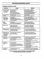
TROUBLE SHOOTING POINTS
TROUBLE
SHOOTING CHART
SYMPTOM
,
,,,
,,
CAUSE
,
REMEDY
,1
•
=
Engine will not start
or will run only for
a few seconds
after starting.
f. Engine switch on stop.
2. Fuel tank empty.
3. Engine flooded.
4. Spark plug not fidng.
5. Fuel not reaching carburetor.
6. Carburetor requires adjustment.
1. Move switchto on position.
2. Fill tank with correct fuel mixture
I 3. See =Starting InstrUctions."
4, Install new plug/check ignitionsystem.
5. Clean fuel filter;,inspect fuel line.
6, See "Carburetor Adjustments,":
•
Engine will not idle
propedy.
1. Air filter is dirty.
2. Carburetor requiresadjustmenL
Engine will not
accelerate,lacks
power, or dies
under a load;
1. Air filter dirty.
2. Spark.plug.:fQuled.: i..
3. Carburetor.requires adjustment.
4. Muffler outlets plugged;-or"sparkarrestor_
screen-obstructed.............
1. Clean or replace air f_er.
2. Clean or replace spark plugand re-gap.
3. See =Carburetor Adjustments."
4, See =Inspect Muffler and spark Arrestor
Screen."
Engine
smokes
excessively.
1. Air filter dirty.
2. Fuel mixture incorrect/Too much oil
3. Carburetor requires adjustmenL
1. Clean or replace air filter.
2. Refuel with correct fuel mixture.
3. See =Carburetor Adjustments."
Engine runs hot.
1. Fuel mixture incorrect.
2. Spark plug incorrect.
3. Carburetor requires adjustmenL
1. See =Before Fueling Engine."
2. Replace with correct plug.
3. See "Carburetor Adjustments."
Cutting attachment
turns at idle speed.
1. Carburetor requires adjustment.
2. Throttle cable binding.
3. Clutch requires repair.
1. See =Carburetor Adjustments."
2. Contact your Sears Service Center.
3. Contact your Sears Service Center.
Cutting attachment
stops under a load
or does not turn
when engine is
accelerated.
1. Carburetor requiresadjustments.
2. Drive shaft broken.
3. Clutch requires repair.
1. See =Carburetor Adjustments."
2. Contact your Sears Service Center.
3. Contact your Sears Service Center.
Line does not
advance or breaks
while cutting.
1. Line.iroprepedy routed in.head ............
2: Line Jmprepedy.wound onto.spool.
3. Une size incorrecL
4. Dirt accumulated on cover cut-outs: ......
5. Line is too old.
1.
2.
3.
4.
5.
Line welds on
spo01/melts together
1. Une size incorrect.
2. Incorrect spool.
3. Line ireproperly wound onto spool,
4. Crowding line against maiedai being cut.
5. Cutting at higher speed than necessary.
6. Line is too old.
t. Use only .095 good quality monofitament line.
2, Use proper Spool.
3. Rewind line tightly and evenly.
4. Cut with tip of line.
5. Reduce cutting speed.
6. Install new line using .095" good quality
monofilament line.
Line pulls back
into head.
1. Too little line outside of head.
2. Line size incorrect.
1. Remove cover. Pull 4" of line to outside.
2. Use .095" good quality monofilament line.
1: Clean air filter.
12.See "Carburetor Adjustments."
Remove cover. Check line routing.
Rewind line tightly and evenly.
Use only ,095" good quality monofitament line;
Clean cover cut-outs.
Install new line using .095" good quality
monofllament line.
ff situations occur which are not covered in this manual, use care and good judgement.
ff you need assistance, contact your SEARS Service Center/Department or the
CUSTOMER ASSISTANCE HOTLINE at 1-800-235-5878.
- 26 -
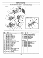
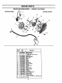
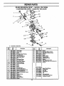
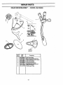
=
REPAIR PARTS
SEARS BRUSHWACKER"
'
5 \
- MODEL 358.798280
/
1
\
/
,@
13
39 \
!5
20
21
29
3
/
32
NO.
2
3
4
5
6
7
8
9
i0
12
13
14
15
16
17
18
19
20
Part
No.
Part
No.
Description_._•
502--203106 Anti-Vibe Holder
503-210722 Screw
502-203202 Anti-Vibe Isolator
502-197101 Nut
502-217003 Mounting Bracket (Inch 16)
502-219301 Thumb Screw
725-238171 Screw
503-098302 Engine Switch
502-199301 Spring
502-1,9104 Throttle Handle (fight side)
503-210738 Screw
502-196002 Handlebar (Incl. 14 & 20).
502-211201 cup
502-204901 Clip
502-217003 Mounting Bracket (Incl. 5)
502-199002 Throttle Handle (left side)
502-199203 Throttle Trigger
502-199403 Throttle Trigger Lock
502-1,9702 Handle Grip
Description
21
24
25
26
27
28
29
502-203304
502-189402
503-161302
503-200230
502-215701
503--521203
502-211101
Outer Housing
Clutch Hous'mg
Clutch Assembly (Complete)
Screw
Clutch Hub
Washer
DriveShaft & HousingAssy
3O
31
32
33
34
35
36
37
502-212901
502-031003
502-045501
502-194601
503-200225
502-185001
503-193601
502-211101
Gearbox Plug
SupportFlange
Nut
Driving
Disk "
Screw
38
39
40
731-231401
503-200230
503-210725
Nut
Screw
Screw
_cL 3D
GearboxAssy.
(ind.
3O)
Gearbox Seal
Drive Shaft'&HousingAssembly
(incL29)
-27-
ii
REPAIR PARTS
i
i
i
i
SEARS BRUSHWACKER
ENGINE
i
TM
' MODEL
358.798280
2
24
5
6
7
9
26
27
41
28
11
30
2\
29
\
22
13
Key
No.
Part
No.
l
so3-n44
2
3
4
5
6
7
8
9
10
II
12
13
14
15
16
17
18
19
20
21
22
23
502-218401
502-198601
502-218602
502-208302
502-206501
502-208402
732-211401
502-198501
503-210747
502-033301
501-278201
503-57890I
503-281505
502-198401
502-212301
502-210601
530-014199
725-537255
503-226301
502-215304
502-212701
502-212801
24
25
502-208201
502-208801
_oey
•
Description
26
Scxew
Cylinder
Cover
Airgdter
.Airlk31ter
Cover :......
Air Filter KnobScrew
Choke Lever..
Nut
Air Filter Housing
Screw
Fuel Cap Assy (Incl. 12 & 13)
"O" Ring IGasket
Fuel Cap Retainer
Carburetor Assy.
Intake Pipe
Support Sleeve
Fuel Line
Fuel Filter
Screw
Clip
Crankcase Assy 0ncL 4 of20)
CrankcaseBearing
Crankshaft & Rod Assy.
(Incl. 2 of 22 and 1 nf31)
Heat Shield
Muffler Gasket
27
28.
29
30
31
Part
No.
so3-z9460i
503-289001
503-686402
503-414101
737-441000
503-797501
Description
Cylinder & Piston Assy
(Incl. 27, 28, 29 & 30)
PistonRing
Piston(hicl.
27)
Needle Bearings
Retaining Clip
Guide Tube
Muffler parts
40
4!
42
43
44
45
46
47
-28-
502--207701
502-216101
5O2-20O001
502-208901
503-200265:
502-196201.
5o2-i99901
502-199.0L
Muffler Reinforcement plate
Distanc e Pipe
Spark Arrestor Screen
Muffler Screen Cover
Screw
Muffler Covea_
Baffle Plate
Muffler Body
43
REPAIR •PARTS
SEARS BRUSHWACKER"
- MODEL
358.798280
IGNITION SYSTEM
STA._II_
gYSTEM
17
1
6
/
/
is
/
22
14
9
/
2_
3__911
11
16
P_rt
N_
-'I
18
Ves_i_o_
'_
, tTmci2.ea. of9,10. & II)
4
5
6
8
9
I0
11
12
13
14
15
16
17
18
19
20
21
22
•:_502_20690r.
501--4&5402
503-2_108
503-202516
,_,3.-_210722
SparkPlugBoot
SparkPlug
Screw
Screw
Washer
&.qO-O420S9 Spring
53O-042058
Starter ]_g
_.q0-015226
Starter D_ Pin
5(_3-230 tO1
_@-221011
Flywheel Nut
Screw
503-2129O6
.'_0_'_..-77530
I Starter Pully
5O2-200601
Starter Spring
503-142902
Washer
502-218501
Air Baffie
502-189881
Throttle Cable Ass,y.
530-037357 Starter Handle
505-305125
Starter
Rope
_)2-218303 Starter
Housing
(lucL7,8,14thru17,& 20thru21
50_210722
Screw
-29-
REPAIR PARTs
'
SEARS BRUSHWACKER
- MODEL 358,798280
CARBURETOR ASSY. - PART NO. 503-281505
TM
19
1
18
2
39
22
7
25
27
28
29
_.
35
14
/.37
o = Included in Gesket Set.
Key
No.
1
2
3
4
5
6
7
8
9
10
11
12D
13m
14
15
16
17
18
19
20o
21 o
22
23
24
25
26
Part
N_
502-213901
506-028101
501-468701
502-I03101
505-316782
,_2-I19701
503-U70_1
505-520125
502-213701
501-666101
503-625201
502-213601
504-130906
501-466901
503-108701
501-468701
502-213201
502-103001
505--316754
504-130808
505-520110
505-316717
505-520127
530-035139
503--574201
502-213501
.27,
504-210049
De_crlptfo.
,,
Choke Shait
ChokeValve
Screw
Th_tle Spring B.ahing
Fast ldl_'Le_er
Choke.Sha_Sprlng
Inlet Needle-Valve ....
Pin
Fuel Inlet Fitting
Fuel Inlet Screen
Scow (IncL W_sher)
Pump Diaphragm
Fud Pump Gasket
Key
No.
128
29
3O
31
32
-34
35
37
38
39
_rew
Screw
Throttle Lever
Throttle Shaft Spacer
MeteringDiapbragm Cover
i
}_eringDiaphragm
Metering Diaphragm Geske_
,Screw
MeteringLevex
Spring
Wdeh Plug
Inlet Valve Seat
i Sprlng
Part
No.
504-210050
503-61Z_01
,503-612401
505-316745
501-468701
5O2-213301
-30-
Spring
Idle Speed l_xture Screw
sp_
5o2-9._4ol
_Ti_ottle Valve
Throttle Shaft
502-2L_801
501-687801
503--10470_
530-O35173
503-581501
Idle Adjustment Screw
Gasket Set (Ind. 12, 13, 20, & 21)
Nozzle
NOT SHOWN
502-114602
502-026101
502-215801
Q
501-_0202
i
504-980020
503-575401
503-575501
503-80460!
....
Description
_d Pump
Spring
Spark Plug Wrench
Lock.Pin
Hex Key
Screwd_vex
Off
W_gVec_
Danger/Warning Decal
Instruction Decal
REPAIR PARTS
•
i
i
i
ii
SEARS BRUSHWAC_R"
- MODEL 358.798280
1
: No;
"
2
503-810101
3
4
6
7
8
9
NO:
, . ,
" ]:_scr'i]rt.ioa
_o2-268_
Blade Transport/Storage Cover
PlasticShield (Incl. Line Limlter)
255mm Weed Blade
225mm Brush Blade
503-736309
Harness Assy (Complete)
503-799301
Metal Shield (Brusheutter use)
530-082400
O_'_r'_
503-811501
Shield Support
502-i75804
-31-
Manual
Plate
I
I
TABLE OF CONTENTS
I
I
Safety Rules . ..............................
..
•
Product Specifications ..........................
Customer Responsibilities ......................
Warranty ......................................
Assembly .......................
"4''°'0"0"0"*0
Operation ....................................
2
4
20
4
6
11
Service and Adjustments .......................
Storage ......................................
Trouble Shooting ..............................
Repair Parts ..................................
Accessories "= ................
0"
*
°°'°°0
0"000°
Repair Parts OideringlService .........
22
25
26
27
; 32
Back Cover
INDEX
I
A
Accessories ..................................
32
Adjustments
Carburetor ..................................
24
Handlebar .................................
12
Shoulder Harness ..........................
12
Air Filter .......................................
21
Assembly ....................................
6-10
B
Blade Sharpening ................................
23
C
Carburetor Adjustments ...................................
24
Conversions
Blade to Line ...............................
8
Line to Blade .............................
9,10
Customer Responsibilities ....................
20-21
Spark Plug ................................
21
Cutting Methods
Line Tdmmer ..............................
17
Brushcutter ................................
15
E
Engine
Fuel/Oil ...................................
18
Spark Plug ................................
21
Starting ..................................
19
Storage ...................................
26
F
Filing Blades ..................................
23
Fueling ....................................
18,26
G
Gearbox Lubrication ...........
: ...............
20
H
Handlebar ....... . ..........................
._................... 6,12
IIII
I I
I
I
Hardware Contents .............................
K
Know Your Brushwacker .......................
L
Line Advancement ............................
Line Umiter ..................................
Line Replacement .............................
M
Maintenance Schedule .........................
Model Number .................................
Muffler ................
O
Operation ..................................
Ordedng Repair Parts ..................
R
Repair Parts ...............................
Ordering ...; ......................
S
Service and Adjustments ....................
Shield
Metal ......................................
Plastic .....................................
Shoulder Harness .............................
Spark Arrestor Screen ........................
Specifications ..................................
Starting ......................................
Storage ......................................
T
Throttle Handle ..............................
Trouble Shooting ..............................
W
Warranty .......................................
II
I
I
5
11
17
8,23
22
20
4
6,21
11-19
Back Cover
27-31
Back Cover
22-24
9
8
12
6,21
4
19
25
6,12
26
4
III
II
ACCESSORIES
II
I
I
II
These accessories and attachments were available when the unit was originally purchased. They are also available at
rnostSearsretailoutletsandservicecenters:
Most Sears stores can order these itemsfor you when you provide the model
number of your unit.
Accessories
' Safety
Goggles
2-exit Manual
Cutting Head
Bulk
Line
Saw Blade
Z
-32-
Brush
Blade
2--Cycle
Engine
Oil
Spark
Plug
_
'
_
3.2o_
8OZ,
1_
°
E_A/RS CRRFTSMRN
Operator's
Manual
Model No.
358.798280
36 cc 2.2 cu.in. 2-CYCLE
16.5 in. Dual Line Head
10.0 in. Brush Tri-blade
8.75 in. Sapling Saw Blade
GAS BRUSHWACKER _
Each Gas Brushwacker® has its own model number. The model
number for your unit will be found on a decal attached to the unit.
All parts listed herein may be ordered through Sears, Roebuck and
Co. Service Centers and most Retail Stores.
IF YOU NEED REPAIR
SERVICE OR PARTS:
WHEN ORDERING REPAIR PARTS, ALWAYS GIVE THE FOLLOWING INFORMATION
• PRODUCT-
REPAIR SERVICE
1-800-4-REPAIR
(1-800-473-7247)
ORDERING PARTS
1-800-FON-PART
(1-800-366-7278)
"GAS BRUSHWACKER"
• MODEL NUMBER - 358.798280
• PART NUMBER
• PART DESCRIPTION
Your Sears merchandise has added _aiue when you consider that
Sears has service unitsnationwide staffed with Sears trained technicians.., professional technicians specifically trained on Sears
products; having_he parts, tools and the equipment to insure that
we meet our pledge to you, we service what we sell.
CUSTOMER
ASSISTANCE
1-800-235-5878
Sears, Roebuck and Co,
530-082400-11/21/94
Hoffman
Estates, IL 60179 USA
101-870491