1
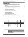
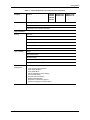
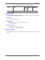
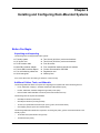
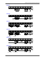
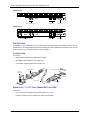
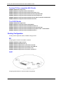
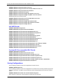
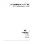
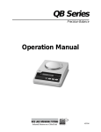
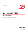
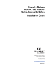
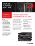
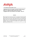
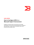
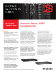
Foundry AR-Series Rack-Mounted Router Quick Installation Guide 2100 Gold Street P.O. Box 649100 San Jose, CA 95164-9100 Tel 408.586.1700 Fax 408.586.1900 June 2004 Copyright © 2004 Foundry Networks, Inc. All rights reserved. No part of this work may be reproduced in any form or by any means – graphic, electronic or mechanical, including photocopying, recording, taping or storage in an information retrieval system – without prior written permission of the copyright owner. The trademarks, logos and service marks (“Marks”) displayed herein are the property of Foundry or other third parties. You are not permitted to use these Marks without the prior written consent of Foundry or such appropriate third party. Foundry Networks, BigIron, FastIron, IronView, JetCore, NetIron, ServerIron, TurboIron, IronWare, EdgeIron, IronPoint, AccessIron, the Iron family of marks and the Foundry Logo are trademarks or registered trademarks of Foundry Networks, Inc. in the United States and other countries. F-Secure is a trademark of F-Secure Corporation. All other trademarks mentioned in this document are the property of their respective owners. Contents CHAPTER 1 GETTING STARTED...................................................................................... 1-1 INTRODUCTION ...........................................................................................................................................1-1 AUDIENCE ..................................................................................................................................................1-1 NOMENCLATURE .........................................................................................................................................1-1 RELATED PUBLICATIONS .............................................................................................................................1-2 LIST OF FEATURES .....................................................................................................................................1-2 HOW TO GET HELP .....................................................................................................................................1-5 WEB ACCESS .......................................................................................................................................1-5 EMAIL ACCESS .....................................................................................................................................1-5 TELEPHONE ACCESS ............................................................................................................................1-5 WARRANTY COVERAGE ...............................................................................................................................1-5 CHAPTER 2 INSTALLING AND CONFIGURING RACK-MOUNTED SYSTEMS .......................... 2-1 BEFORE YOU BEGIN ..................................................................................................................................2-1 UNPACKING AND INSPECTING ................................................................................................................2-1 ADDITIONAL CABLES, TOOLS, AND MATERIALS ......................................................................................2-1 INSTALLATION SITE ...............................................................................................................................2-2 PORTS AND CONNECTIONS ........................................................................................................................2-2 DIAL-OUT PORTS .................................................................................................................................2-4 CONSOLE CABLE ..................................................................................................................................2-4 ETHERNET, E1, T1, CT3, CLEAR CHANNEL DS3, AND USSI .................................................................2-4 ALARMS ...............................................................................................................................................2-5 POWER ................................................................................................................................................2-5 MANAGEMENT INTERFACE ..........................................................................................................................2-5 INITIAL CONFIGURATION .......................................................................................................................2-5 INTERFACE CONFIGURATION ......................................................................................................................2-6 T1 INTERFACE .....................................................................................................................................2-7 E1 INTERFACE .....................................................................................................................................2-7 June 2004 © 2004 Foundry Networks, Inc. iii Foundry AR-Series Rack-Mounted Router Quick Installation Guide BUNDLE CONFIGURATION ...........................................................................................................................2-7 FRACTIONAL T1/CISCO-COMPATIBLE HDLC BUNDLE .............................................................................2-8 T1OR E1/PPP BUNDLE ........................................................................................................................2-8 ROUTING CONFIGURATION .........................................................................................................................2-8 RIP .....................................................................................................................................................2-8 OSPF .................................................................................................................................................2-8 BGP4 ..................................................................................................................................................2-9 NXE1/MFR BUNDLE ..........................................................................................................................2-10 FRACTIONAL E1/CISCO-COMPATIBLE HDLC BUNDLE ...........................................................................2-10 SAVING CONFIGURATIONS ........................................................................................................................2-10 LEDS ......................................................................................................................................................2-11 iv © 2004 Foundry Networks, Inc. June 2004 Chapter 1 Getting Started Introduction This guide describes how to install and configure a rack-mounted AR1208-T, AR1208-E, AR1216-T, AR1216-E, AR3201-T-CL, AR3202-T-CL, AR3201-T-CH, and AR3202-T-CH router. Audience This manual is designed for system administrators with a working knowledge of Layer 2 and Layer 3 switching and routing. If you are using a Foundry Layer 3 Switch, you should be familiar with the following protocols if applicable to your network – IP, RIP, OSPF, BGP4, IGMP, PIM, and VRRP. Nomenclature This guide uses the following typographical conventions to show information: Italic highlights the title of another publication and occasionally emphasizes a word or phrase. Bold highlights a CLI command. Bold Italic highlights a term that is being defined. Underline highlights a link on the Web management interface. Capitals highlights field names and buttons that appear in the Web management interface. NOTE: A note emphasizes an important fact or calls your attention to a dependency. WARNING: A warning calls your attention to a possible hazard that can cause injury or death. CAUTION: June 2004 A caution calls your attention to a possible hazard that can damage equipment. © 2004 Foundry Networks, Inc. 1-1 Foundry AR-Series Rack-Mounted Router Quick Installation Guide Related Publications The following Foundry Networks documents supplement the information in this guide. • Release Notes Printed release notes provide the latest information. If release notes are provided with your product, follow the instructions contained within them instead of those provided in other documentation. • Foundry AR-Series Rack-Mounted Router Installation Guide This detailed guide provides detailed installation and configuration steps for installing Foundry AccessIron rack-mounted routers. • Foundry AR-Series Router Configurations Guide This guide provides examples of AccessIron configurations. • Foundry AR-Series Router Command Reference Guide This guide explains the syntax and application of AccessIron router CLI commands. • Foundry AR-Series Router User Guide This guide explains the AccessIron router features. To order additional copies of these manuals, do one of the following: • Call 1.877.TURBOCALL (887.2622) in the United States or 1.408.586.1881 outside the United States. • Send email to [email protected]. List of Features June 2004Table 1.1 shows the features supported on AccessIron devices. Table 1.1: Feature Supported in AccessIron Devices Category Feature AR1202 AR1204 AR1208 AR1216 AR3201-T-CL AR3202-T-CL AR3201-T-CH AR3202-T-CH 10/100 Fast Ethernet 2 2 2 T1/E1 Yes - - Channelized T3 - - Yes Clear Channel T3 - Yes - Interfaces WAN/LAN WAN Protocols PPP, PAP, Multilink PPP, Frame Relay, Multilink Frame Relay, (FRF.15, FRF.16.1) BCP, HDLC Layer 2 Features 802.1Q VLAN tagging and forwarding over WLAN Virtual LAN Domain (VLD) VLAN Double Tagging Transparent Bridging Jumbo Frames (4072 bytes) 1-2 © 2004 Foundry Networks, Inc. June 2004 Getting Started Table 1.1: Feature Supported in AccessIron Devices (Continued) Category Feature AR1202 AR1204 AR1208 AR1216 AR3201-T-CL AR3202-T-CL AR3201-T-CH AR3202-T-CH IP Multiplexing NAT mode Transparent Layer 3 packet forwarding Layer 3 Features Routing RIPv1/v2 OSPF BGP4 Static Routing ECMP (IP load balancing) Multicast (PIM-SM, PIM-SSM, IGMP v2/v3) High Availability VRRP BGP4 Multi-homing Bundle Tracking MLPPP Bundle Thresholding LAN Interface Load Sharing with Failover Security/ Management June 2004 Stateful Packet Inspection Firewall with: Layer-3 mode (router and NAT) Policy-based NAT/PAT Policy-based filters URL and application content filtering Time and rate limiting Denial of Service protection Network attack detection Application Level Gateway support Packet-level logging and syslog support © 2004 Foundry Networks, Inc. 1-3 Foundry AR-Series Rack-Mounted Router Quick Installation Guide Table 1.1: Feature Supported in AccessIron Devices (Continued) Category Feature AR1202 AR1204 AR1208 AR1216 AR3201-T-CL AR3202-T-CL AR3201-T-CH AR3202-T-CH VPN - - ACLs DHCP TFTP PAP RADIUS TACACS+ SSH v2 GRE Tunneling IPSec VPN with integrated IKE Site-to-site VPN Site-to-remote VPN MD5 & SHA-1 authentication Hardware accelerated encryption 3DES (168 bit), DES (56 bit), AES (256 bit) encryption QoS/Traffic Management optional on the AR1202 and AR1204 RED DiffServ Class-based Queuing per: IP address Flow VLAN tag Application port Frame Relay traffic shaping and policing VLAN-802.1P 8 queue prioritization of VLAN frames Service Provisioning Management (in-band, serial, Telnet, or modem) by: CLI SNMP Monitoring syslog Statistics Alarms Diagnostics BERT Loopback testing Traceroute Reverse Telnet Specialized Features 1-4 Hospitality Web Redirection © 2004 Foundry Networks, Inc. June 2004 Getting Started Table 1.1: Feature Supported in AccessIron Devices (Continued) Category Feature AR1202 AR1204 AR1208 AR1216 AR3201-T-CL AR3202-T-CL AR3201-T-CH AR3202-T-CH Timed Access List How to Get Help Foundry Networks technical support will ensure that the fast and easy access that you have come to expect from your Foundry Networks products will be maintained. Web Access • http://www.foundrynetworks.com Email Access Technical requests can also be sent to the following email address: • [email protected] Telephone Access • 1.877.TURBOCALL (887.2622) United States • 1.408.586.1881 Outside the United States Warranty Coverage Contact Foundry Networks using any of the methods listed above for information about the standard and extended warranties. June 2004 © 2004 Foundry Networks, Inc. 1-5 Foundry AR-Series Rack-Mounted Router Quick Installation Guide 1-6 © 2004 Foundry Networks, Inc. June 2004 Chapter 2 Installing and Configuring Rack-Mounted Systems Before You Begin Unpacking and Inspecting The following items are shipped with these systems. Foundry system Two 19-inch (48.26 cm) rack-mount brackets AC power cord Two 23-inch (58.42 cm) rack-mount brackets RJ-45 console cable Four #6 screws Male DB-9 modular adapter Four each #6 flat washers and #6 lock washers Female DB-9 modular adapter Product Documentation CD-ROM Four self-adhering rubber feet Registration card Quick start guide Warranty form If any of the above items are missing or defective, contact Foundry. Additional Cables, Tools, and Materials The following additional cables are required for integrating these systems with other networking devices. • RJ-45, male/male, Category 5, shielded, twisted pair cable (Ethernet ports) • RJ-48C, male/male, shielded, straight-through cable (T1/E1 ports) • RG-59 coaxial cables with BNC connectors (Clear Channel DS3 and CT3) The following tools are required for installation. • #3 Phillips screwdriver (rackmount) • #2 Phillips screwdriver (mounting bracket) • 1/8 inch (3 mm) flat-blade screwdriver (DC power, ground, and external alarm) • wire stripping tool (DC power and external alarm) The following additional materials are required for connecting DC power, ground, and external alarms to the Foundry system. • 18-22 AWG wire (external alarm and ground) • 18 AWG wire (DC power) June 2004 © 2004 Foundry Networks, Inc. 2-1 Foundry AR-Series Rack-Mounted Router Quick Installation Guide Installation Site These systems are designed to be installed in a 19- or 23-inch (48.26 or 58.42 cm) rack or on a flat, stable surface with sufficient space to accommodate a 12- x 19-inch (30.48 x 48.26 cm) footprint. The installation site should provide ample room for connecting cables and performing maintenance, and the site should not be subject to extreme temperature shifts. The Foundry system should be located in close proximity to all relevant telecommunication ports and power supplies. Ports and Connections The following diagrams and sections identify models and provide information about connecting AC and DC power, network cables, and alarm and ground wires. 2-2 © 2004 Foundry Networks, Inc. June 2004 Installing and Configuring Rack-Mounted Systems AR1208-T Octal T1 1 2 3 WAN 4 Link Status 1 2 Ethernet 0 3 4 5 6 7 Ethernet 1 Console Unit 1400 8 ESD Gnd Mon. TX Col HS TX Col HS Summary RX Link Dup RX Link Dup Power Status 5 6 7 8 T1 Ports Ethernet Ports Console Port AR1208-E Octal E1 1 2 3 WAN 4 Link Status 1 2 Ethernet 0 3 4 5 6 7 Ethernet 1 Console Unit 1400E 8 ESD Gnd Mon. TX Col HS TX Col HS Summary RX Link Dup RX Link Dup Power Status 5 Monitor Port 6 7 8 E1 Ports Console Port Ethernet Ports AR1216-T Octal E1 1 2 3 WAN 4 Octal E1 Mon. 9 10 11 WAN 12 Mon. Status 5 6 7 Link Status Ethernet 0 1 2 3 4 5 6 7 8 9 10 11 12 13 14 15 16 Ethernet 1 Console Unit 6200E ESD Gnd TX Col HS TX Col HS Summary RX Link Dup RX Link Dup Power Status 8 13 T1 Ports 14 15 16 Ethernet Ports T1 Ports Console Port AR1216-E Octal E1 1 2 3 WAN 4 Octal E1 Mon. 9 10 11 WAN 12 Mon. Status 5 6 7 Link Status Ethernet 0 1 2 3 4 5 6 7 8 9 10 11 12 13 14 15 16 Console Unit 6200E ESD Gnd Col HS TX Col HS Summary RX Link Dup RX Link Dup Power Status 8 13 E1 Ports 14 15 16 E1 Ports Monitor Port Ethernet 1 TX Console Port Ethernet Ports Monitor Port AR3201-T-CH Channelized T3 DS3 WAN Link Status 1 RX TX Mon. Test AIS Status Error 2 Ethernet 0 3 4 5 6 7 Signal Ethernet 1 Console Unit 6300 8 9 10 11 12 13 14 15 16 17 18 19 20 21 22 23 24 25 26 27 28 ESD Gnd Yellow Frame TX Col HS TX Col HS Summary RX Link Dup RX Link Dup Power Ethernet Ports Channelized T3 Ports Console Port AR3202-T-CH Channelized T3-1 DS3 WAN Channelized T3-2 DS3 WAN Link Status 1 RX TX Mon. RX Test AIS TX Test AIS Status Channelized T3 Ports June 2004 Signal 4 5 7 8 10 11 12 13 14 15 16 17 18 19 20 21 22 Frame Error Channelized T3 Ports Signal 6 23 24 Status 25 26 27 28 C1 C2 Frame Ethernet 1 Console Unit 6302 ESD Gnd Select Yellow Select Error 2 Ethernet 0 3 9 Select Mon. Yellow TX Col HS TX Col HS Summary RX Link Dup RX Link Dup Power Ethernet Ports © 2004 Foundry Networks, Inc. Console Port 2-3 Foundry AR-Series Rack-Mounted Router Quick Installation Guide AR3201-T-CL Clear Channel T3 RX DS3 WAN Ethernet 0 Ethernet 1 Console Unit 4100 ESD Gnd TX Test AIS Yellow Error Signal Frame TX Col HS TX Col HS Summary RX Link Dup RX Link Dup Power Status Clear Channel DS3 Ports Console Port Ethernet Ports AR3202-T-CL Clear Channel T3-1 RX DS3 WAN Clear Channel T3-2 TX RX Test AIS Yellow Error Signal Frame DS3 WAN Ethernet 0 Ethernet 1 Console Unit 4102 ESD Gnd TX Test AIS Yellow Error Signal Frame Status TX Col HS TX Col HS Summary RX Link Dup RX Link Dup Power Status Clear Channel DS3 Ports Console Port Ethernet Ports Dial-Out Ports The AR3202-T-CL, and AR3202-T-CH have a dial-out port on the back panel that is used to notify the network administrator or other designated person about captured system traps. Notification procedures can be set up to meet the needs of the customer via pager or phone message. Console Cable Connect the: • DB-9 modular adapters to the supplied RJ-45 cable • Male DB-9 modular adapter to the console port • Female DB-9 modular adapter to a terminal or PC Female Adapter Foundry System Port Terminal or Workstation Console Cable Male Adapter Ethernet, E1, T1, CT3, Clear Channel DS3, and USSI Connect the: 2-4 • RJ-45 connector of an Ethernet cable to the Ethernet 0 or 1 port • RJ-48C connectors of the T1 cables to the T1/E1 ports (AR1208) © 2004 Foundry Networks, Inc. June 2004 Installing and Configuring Rack-Mounted Systems Alarms Connect the stripped ends of two 18-22 AWG wires to alarm terminals 6 and 7 on the back-panel terminal block. AC Receptacle 100-240V FUSE: T3A, 250V SLOW BLOW 5- SEE PRODUCT MANUAL 1 FOR CENTRALIZED DC POWER, INSTALL ONLY IN RESTRICTED ACCESS AREAS 2 3 40 - 60V 4 5 6 , 3.0A 7 CAUTION: TO PROTECT AGAINST RISK OF FIRE, REPLACE WITH THE SAME TYPE AND RATING OF FUSE ONLY. , 2.5A, 50-60Hz 1 - 48B RTN 2 - 48B 3 - 48A RTN 4 - 48A 5 - 7 in-lbs 0.57 - 0.79 N-m TORQUE 6 - ALARM CONTACT 7 - ALARM COMMON ESD GND SUMMARY AUX. PORT CAUTION: TO PROTECT AGAINST RISK OF ELECTRICAL SHOCK, DISCONNECT BOTH AC POWER CORD AND DC WIRING BEFORE SERVICING. POWER Alarm Terminals Power Foundry systems operate on AC, single DC, and dual DC power. For AC power operation, connect the female end of the supplied AC power cord to the AC power receptacle on the system back panel. Connect the male end of the AC cord to a standard 110/120 VAC source. Refer to the figure above. Refer to the Installation Guide: Domestic Products for information about dual AC power connection. To operate with single-source DC power, connect the stripped ends of two 18-AWG wires to either the A or B terminals on the terminal block. Make sure to connect the +48V lead to the appropriate RTN connector. CAUTION: To avoid equipment damage, make sure that the +48V lead is connected to the appropriate RTN connector (either 1 or 3) on the terminal block. To operate with dual-source DC power, connect the stripped ends of four 18-AWG wires to the both the A and B terminals on the terminal block. Make sure to connect the +48V leads to the appropriate RTN connectors. Management Interface To access the command line interface (CLI) via the front-panel console port, connect a terminal or a workstation running a terminal emulation software to the Foundry system. The software should be configured as follows: • 9600 bps • 8 data bits • 1 stop bit • No parity • XON/XOFF flow control To remotely access the system, configure the modem data port as specified above for terminal emulation software. It is also possible to telnet to the Foundry system once an IP address is assigned to an Ethernet port. Initial Configuration Use the following commands to log in as the system administrator, choose a host name, change the password, set the system time, and enter an Ethernet IP address. June 2004 © 2004 Foundry Networks, Inc. 2-5 Foundry AR-Series Rack-Mounted Router Quick Installation Guide Logging In EXAMPLE:Login: foundry EXAMPLE:Password: foundry Choosing a Host Name EXAMPLE:AR1208# configure term EXAMPLE:AR1208/configure# hostname ISP_name Changing the Password EXAMPLE:AR1208# password EXAMPLE:name: foundry EXAMPLE:old password: foundry EXAMPLE:new password: new_pass EXAMPLE:re-enter password: new_pass Passwords are case-sensitive and must be a minimum of three to a maximum of eight characters. Make a note of the password that you use. Setting the System Date and Time EXAMPLE:AR1208# configure term EXAMPLE:AR1208/configure# date - 0 0 mo 3 d 19 y 2000 h 14 mi 40 s 35 The first portion of this command, date - 0 0, establishes offset from GMT. The minus sign inputs offset direction, and the two numbers input offset hours and minutes. The second portion of this command, mo 3 d 19 y 2000 h 14 mi 40 s 35, inputs the local month, day, year, hour, minute, and second. Entering an Ethernet IP Address and Subnet Mask EXAMPLE:AR1208# configure term EXAMPLE:AR1208/configure# interface ethernet 0 EXAMPLE:AR1208/configure/interface/ethernet 0# ip address 10.1.100.28 255.255.255.0 Interface Configuration The following are examples of T1, CT3, and DS3 interface configurations. To scroll through the options available at any command prompt, press the Tab key. For descriptions of the options available at any command prompt, type help and press Enter. 2-6 © 2004 Foundry Networks, Inc. June 2004 Installing and Configuring Rack-Mounted Systems T1 Interface EXAMPLE:AR1208-T# configure term EXAMPLE:AR1208-T/configure# module t1 4 EXAMPLE:AR1208-T/configure/module/t1 4# clock_source line EXAMPLE:AR1208-T/configure/module/t1 4# framing esf EXAMPLE:AR1208-T/configure/module/t1 4# linecode b8zs EXAMPLE:AR1208-T/configure/module/t1 4# yellow_alarm gen_det EXAMPLE:AR1208-T/configure/module/t1 4# exit 3 E1 Interface EXAMPLE:AR1208-E# configure term EXAMPLE:AR1208-E/configure# module e1 4 EXAMPLE:AR1208-E/configure/module/e1 4# clock_source line EXAMPLE:AR1208-E/configure/module/e1 4# framing crc EXAMPLE:AR1208-E/configure/module/e1 4# exit 2 EXAMPLE:AR1208-E/configure# cabletype monitor_port 1 twisted_pair EXAMPLE:AR1208-E/configure# module e1 4 EXAMPLE:AR1208-E/configure/module/e1 4# linecode hdb3 EXAMPLE:AR1208-E/configure/module/e1 4# yellow_alarm gen_det EXAMPLE:AR1208-E/configure/module/e1 4# exit 3 Bundle Configuration Foundry systems support PPP, MLPPP, FR, MFR, and Cisco-compatible HDLC for WAN data transmission. NOTE: Bundle names cannot exceed eight characters. The following are examples of bundles configured for T1/E1, fractional T1/E1, and NxT1/NxE1 transmission. June 2004 © 2004 Foundry Networks, Inc. 2-7 Foundry AR-Series Rack-Mounted Router Quick Installation Guide Fractional T1/Cisco-compatible HDLC Bundle EXAMPLE:AR1208-T# configure term EXAMPLE:AR1208-T/configure# interface bundle Denver EXAMPLE:AR1208-T/configure/interface/bundle Denver# link t1 3:1-6 EXAMPLE:AR1208-T/configure/interface/bundle Denver# encapsulation hdlc EXAMPLE:AR1208-T/configure/interface/bundle Denver# hdlc keepalive 20 EXAMPLE:AR1208-T/configure/interface/bundle Denver# ip address 192.168.2.1 255.255.255.0 EXAMPLE:AR1208-T/configure/interface/bundle Denver# exit 3 T1or E1/PPP Bundle EXAMPLE:AR1208-T# configure term EXAMPLE:AR1208-T/configure# interface bundle Boston EXAMPLE:AR1208-T/configure/interface/bundle Boston# link t1 4 EXAMPLE:AR1208-T/configure/interface/bundle Boston# encapsulation ppp EXAMPLE:AR1208-T/configure/interface/bundle Boston# ip address 199.1.1.1 255.255.255.0 EXAMPLE:AR1208-T/configure/interface/bundle Boston# exit 3 Routing Configuration Foundry products support RIP, OSPF, and BGP4 routing protocols. RIP Configuring RIP for Ethernet 0 and WAN 1 interfaces. EXAMPLE:AR1208# configure terminal EXAMPLE:AR1208/configure# router rip EXAMPLE:AR1208/configure/router rip# interface ethernet0 EXAMPLE:AR1208/configure/router rip/interface ethernet0# exit EXAMPLE:AR1208/configure/router rip# interface wan1 EXAMPLE:AR1208/configure/router rip/interface wan1# exit 3 OSPF Configuring OSPF between a LAN and a WAN running MLPPP. 2-8 © 2004 Foundry Networks, Inc. June 2004 Installing and Configuring Rack-Mounted Systems EXAMPLE:AR1208-T# configure terminal EXAMPLE:AR1208-T/configure# interface ethernet 0 EXAMPLE:AR1208-T/configure/interface/ethernet 0# ip address 10.10.10.1 24 EXAMPLE:AR1208-T/configure/interface/ethernet 0# exit 2 EXAMPLE:AR1208-T/configure# interface bundle Dallas EXAMPLE:AR1208-T/configure/interface/bundle Dallas# link ct3 1 1-10 EXAMPLE:AR1208-T/configure/interface/bundle Dallas# encapsulation ppp EXAMPLE:AR1208-T/configure/interface/bundle Dallas# ip address 20.20.20.1 24 EXAMPLE:AR1208-T/configure/interface/bundle Dallas# exit 2 EXAMPLE:AR1208-T/configure# router routerid 10.10.10.1 EXAMPLE:AR1208-T/configure# router ospf EXAMPLE:AR1208-T/configure/router/ospf# area 760 EXAMPLE:AR1208-T/configure/router/ospf/area 760# exit EXAMPLE:AR1208-T/configure/router/ospf# interface Dallas area_id 760 EXAMPLE:AR1208-T/configure/router/ospf/interface Dallas# cost 10 EXAMPLE:AR1208-T/configure/router/ospf/interface Dallas# exit EXAMPLE:AR1208-T/configure/router/ospf#interface ethernet0 area_id 760 EXAMPLE:AR1208-T/configure/router/ospf/interface ethernet0# cost 10 EXAMPLE:AR1208-T/configure/router/ospf/interface ethernet0# priority 0 EXAMPLE:AR1208-T/configure/router/ospf/interface ethernet0# exit 3 BGP4 Configuring EBGP between two different autonomous systems. EXAMPLE:AR1208-T/configure# interface bundle Chicago EXAMPLE:AR1208-T/configure/interface/bundle Chicago# link ct3 1 1-10 EXAMPLE:AR1208-T/configure/interface/bundle Chicago# encapsulation ppp EXAMPLE:AR1208-T/configure/interface/bundle Chicago# ip address 20.20.20.1 24 EXAMPLE:AR1208-T/configure/interface/bundle Chicago# exit EXAMPLE:AR1208-T/configure# router bgp 10 EXAMPLE:AR1208-T/configure/router/bgp 10# neighbor 20.20.20.2 20 EXAMPLE:AR1208-T/configure/router/bgp 10/neighbor 20.20.20.2 20# exit 3 Configuring IBGP between two neighbors in the same autonomous system. June 2004 © 2004 Foundry Networks, Inc. 2-9 Foundry AR-Series Rack-Mounted Router Quick Installation Guide EXAMPLE:AR1208-T/configure# interface ethernet 0 EXAMPLE:AR1208-T/configure/interface/ethernet 0# ip address 10.10.10.1 24 EXAMPLE:AR1208-T/configure/interface/ethernet 0# exit EXAMPLE:AR1208-T/configure# router bgp 10 EXAMPLE:AR1208-T/configure/router/bgp 10# neighbor 10.10.10.2 10 EXAMPLE:AR1208-T/configure/router/bgp 10/neighbor 10.10.10.2 10# exit 3 Redistributing static and connected routes. EXAMPLE:AR1208-T/configure# ip route 9.9.0.0 255.255.0.0 10.10.10.10 EXAMPLE:AR1208-T/configure# router bgp 10 EXAMPLE:AR1208-T/configure/router/bgp 10# redistribute static EXAMPLE:AR1208-T/configure/router/bgp 10# redistribute connected EXAMPLE:AR1208-T/configure/router/bgp 10# exit 2 NxE1/MFR Bundle EXAMPLE:AR1208-E# configure term EXAMPLE:AR1208-E/configure# interface bundle Madrid EXAMPLE:AR1208-E/configure/interface/bundle Madrid# link e1 3-4 EXAMPLE:AR1208-E/configure/interface/bundle Madrid# encapsulation fr EXAMPLE:AR1208-E/configure/interface/bundle Madrid# fr EXAMPLE:AR1208-E/configure/interface/bundle Madrid/fr# intf_type dce EXAMPLE:AR1208-E/configure/interface/bundle Madrid/fr# lmi EXAMPLE:AR1208-E/configure/interface/bundle Madrid/fr/lmi# keepalive 12 EXAMPLE:AR1208-E/configure/interface/bundle Madrid/fr/lmi# exit EXAMPLE:AR1208-E/configure/interface/bundle Madrid/fr# pvc 16 EXAMPLE:AR1208-E/configure/interface/bundle Madrid/fr/pvc 16# shaping cir 1920000 EXAMPLE:AR1208-E/configure/interface/bundle Madrid/fr/pvc 16# exit EXAMPLE:AR1208-E/configure/interface/bundle Madrid/fr# enable interface EXAMPLE:AR1208-E/configure/interface/bundle Madrid/fr# exit 4 Fractional E1/Cisco-compatible HDLC Bundle EXAMPLE:AR1208-E# configure term EXAMPLE:AR1208-E/configure# interface bundle London EXAMPLE:AR1208-E/configure/interface/bundle London# link e1 3:1-6 EXAMPLE:AR1208-E/configure/interface/bundle London# encapsulation hdlc EXAMPLE:AR1208-E/configure/interface/bundle London# hdlc keepalive 20 EXAMPLE:AR1208-E/configure/interface/bundle London# ip address 192.168.2.1 255.255.255.0 EXAMPLE:AR1208-E/configure/interface/bundle London# exit 3 Saving Configurations Use the following command to save new configurations to system memory. EXAMPLE:AR1208# write mem Use the following command to save new configurations to a network host for archiving and back-up purposes. Identify the host name or IP address, the host directory the file is being transferred to, and the new name as follows. EXAMPLE:AR1208# save network 10.1.100.149 /maindir/config01.txt When saving to a network host, the host directory and file name must pre-exist. 2 - 10 © 2004 Foundry Networks, Inc. June 2004 Installing and Configuring Rack-Mounted Systems LEDs The Foundry system front-panel LEDs indicate real-time unit status. The following table provides information about how to interpret the various LED states. For more detailed LED descriptions, refer to the Foundry Installation Guide: Domestic Products. LED State Description Off Indicates an absence of power, a deselected function, or an outof-service link Green Indicates either an engaged or a properly functioning feature Yellow Indicates an out-of-service test or a failed DC converter (Power LED) Green or yellow with blinking red Same as above conditions for green and yellow, but one or more of the following errors have been detected on a T1 port: Framing bit errors CRC-6 errors (in ESF mode) Line code violations Red June 2004 Indicates either an error, an alarm, or a loss of signal © 2004 Foundry Networks, Inc. 2 - 11 Foundry AR-Series Rack-Mounted Router Quick Installation Guide 2 - 12 © 2004 Foundry Networks, Inc. June 2004