1
Dell PowerEdge
Modular Systems
Hardware Owner’s
Manual
Notes, Cautions, and Warnings
NOTE: A NOTE indicates important information that helps you make better use of
your computer.
CAUTION: A CAUTION indicates potential damage to hardware or loss of data if
instructions are not followed.
WARNING: A WARNING indicates a potential for property damage, personal
injury, or death.
____________________
Information in this publication is subject to change without notice.
© 2008–2011 Dell Inc. All rights reserved.
Reproduction of these materials in any manner whatsoever without the written permission of Dell Inc.
is strictly forbidden.
Trademarks used in this text: Dell™, the DELL logo, PowerEdge™, and PowerConnect™ are
trademarks of Dell Inc. AMD® and AMD Opteron® are either trademarks or registered trademarks of
Advanced Micro Devices, Inc. Intel® and Xeon® are registered trademarks of Intel Corporation in the
U.S. and other countries. Microsoft®, MS-DOS®, Windows®, and Windows Server® are registered
trademarks of Microsoft Corporation in the United States and/or other countries. Cisco® is a registered
trademark of Cisco Systems Inc.
Other trademarks and trade names may be used in this publication to refer to either the entities claiming
the marks and names or their products. Dell Inc. disclaims any proprietary interest in trademarks and
trade names other than its own.
March 2011
Rev. A06
Contents
1
About Your System .
. . . . . . . . . . . . . . . . .
Accessing System Features During Start-up
System Overview.
. . . . . .
13
. . . . . . . . . . . . . . . . . . . .
14
System Control Panel Features
LCD Module
13
. . . . . . . . . . . . .
16
. . . . . . . . . . . . . . . . . . . . . . .
18
LCD Module Features .
. . . . . . . . . . . . . . .
Using the LCD Module Menus
Blade Features .
19
. . . . . . . . . . .
19
. . . . . . . . . . . . . . . . . . . . .
22
. . . .
31
Hard-Drive Features .
. . . . . . . . . . . . . . . . . .
31
Back-Panel Features
. . . . . . . . . . . . . . . . . .
34
Using USB Diskette or USB DVD/CD Drives
. . . . . . . . . . . . . .
36
. . . . . . . . . . . . . . .
37
Power Supply Indicator.
Fan Module Indicators
. . . . . . . . . . . . . .
38
. . . . . . . . . . . . . . . . . . . . . .
41
Identifying Midplane Version
iKVM Module
Tiering the Avocent iKVM Switch From
an Analog KVM Switch . . . . . . . . .
. . . . . .
44
Tiering the Avocent iKVM Switch From
a Digital KVM Switch . . . . . . . . . .
. . . . . .
46
. . . . . . . . . . . . . . . . . . . . . .
48
CMC Module .
I/O Connectivity
. . . . . . . . . . . . . . . . . . . . .
Contents
52
3
Guidelines for Installing I/O Modules .
. . . . . . .
52
Port Auto-Disablement in Quad-Port
Network Daughter Card
(PowerEdge M710HD Only) . . . . . .
. . . . . . .
53
. . . . . . . . . . . . . . . . . .
55
Mezzanine Cards
I/O Module Port Mapping .
. . . . . . . . . . . . .
Dell PowerConnect-KR 8024-k Switch
Dell M8428-k 10 Gb Converged
Network Switch . . . . . . . . .
. . . . . . .
69
. . . . . . . . . .
71
Mellanox M3601Q QDR Infiniband
Switch I/O Module . . . . . . . .
Mellanox M2401G Infiniband
Switch I/O Module . . . . .
. . . . . . . . .
73
. . . . . . . . . . . .
74
Cisco SFS M7000e Infiniband
Switch Module . . . . . . . .
Cisco Ethernet Switch
. . . . . . . . . . .
75
. . . . . . . . . . . . . . .
77
PowerConnect M6348 1 Gb Ethernet
Switch I/O Module . . . . . . . . . .
. . . . . . .
79
PowerConnect M8024 10 Gb Ethernet
Switch I/O Module . . . . . . . . . .
. . . . . . .
81
. . . . . . . . . .
83
PowerConnect M6220 Ethernet
Switch Module . . . . . . . . .
Dell 10 GbE KR Pass-Through I/O Module
Dell 8/4 Gbps Fibre Channel
Pass-Through I/O Module .
. . . . .
85
. . . . . . . . . . . .
86
10 Gb Ethernet Pass-Through Module II
. . . . . .
10 Gb Ethernet Pass-Through I/O Module
. . . . .
4 Gbps Fibre Channel Pass-Through Module.
Brocade M5424 FC8 I/O Module
10/100/1000 Mb Ethernet
Pass-Through Module .
LCD Status Messages
90
92
. . . . . . . . . .
95
. . . . . . . . .
98
. . . . . . . . . . . . .
101
. . . . . . . . . . . . . . . . .
103
Viewing Status Messages
. . . . . . . . . . . .
Removing LCD Status Messages .
Contents
88
. . .
Brocade M4424 SAN I/O Module .
4
58
. . . . . . . .
103
103
System Messages
. . . . . . . . . . . . . . . .
134
. . . . . . . . . . . . . . . . .
135
. . . . . . . . . . . . . . . . . . . . .
135
Warning Messages .
Diagnostics Messages
Alert Messages
2
115
. . . . . . . . . . . . . . . . . . . .
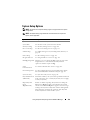
Using the System Setup Program
and UEFI Boot Manager . . . . . . .
Choosing the System Boot Mode
. . . . .
137
. . . . . . . . . . . .
137
Entering the System Setup Program .
. . . . . . . . . .
138
Responding to Error Messages.
. . . . . . . . . .
138
Using the System Setup Program
Navigation Keys. . . . . . . . . .
System Setup Options
. . . . . . . . .
138
. . . . . . . . . . . . . . . . . .
139
Memory Settings Screen .
. . . . . . . . . . . . .
Processor Settings Screen .
. . . . . . . . . . . .
SATA Settings Screen (PowerEdge
M610, M610x) . . . . . . . . . . . .
Boot Settings Screen .
140
141
. . . . . . . .
143
. . . . . . . . . . . . . . .
143
Integrated Devices Screen .
. . . . . . . . . . . .
144
PCI IRQ Assignments Screen .
. . . . . . . . . . .
146
Serial Communication Screen
. . . . . . . . . . .
146
Power Management Screen (PowerEdge
M915, M910, M710, M710HD,
M610 and M610x Only) . . . . . . . . . .
. . . . .
147
. . . . . . . . . . . . . .
148
. . . . . . . . . . . . . . . . . . . . .
149
System Security Screen
Exit Screen
. . . . . . . . . . . .
150
UEFI Boot Manager Screen
. . . . . . . . . . . .
150
UEFI Boot Settings Screen .
. . . . . . . . . . . .
150
. . . . . . . . . . . . . .
151
Entering the UEFI Boot Manager
System Utilities Screen .
Contents
5
System and Setup Password Features.
. . . . . . . .
151
. . . . . . . . . . .
151
. . . . . . . . . . . .
153
Using the System Password
Using the Setup Password
3
Installing Blade Components .
Recommended Tools .
. . . . . . . .
155
. . . . . . . . . . . . . . . . .
155
. . . . . . . . . . .
155
. . . . . . . . . . . . . . . .
155
. . . . . . . . . . . . . . . . .
158
Removing and Installing a Blade
Removing a Blade .
Installing a Blade
. . . . . . .
158
Removing a Blade Blank
. . . . . . . . . . . . .
158
Installing a Blade Blank .
. . . . . . . . . . . . .
159
Removing and Installing a Blade Blank .
. . . . . . . . . . . .
159
Opening the Blade
. . . . . . . . . . . . . . . .
159
Closing the Blade .
. . . . . . . . . . . . . . . .
161
. . . . . . . . . . . . . . . . . . .
162
. . . . . . . . . . . . . . . . . . . .
171
Opening and Closing the Blade
Inside the System.
System Memory
System Memory – PowerEdge M915 .
. . . . . .
171
System Memory – PowerEdge M910 .
. . . . . .
177
System Memory – PowerEdge M905 .
. . . . . .
181
System Memory – PowerEdge M805 .
. . . . . .
184
System Memory – PowerEdge M710 .
. . . . . .
188
System Memory – PowerEdge M710HD
System Memory – PowerEdge
M610/M610x . . . . . . . . . .
6
Contents
. . . . .
194
. . . . . . . . . .
199
System Memory – PowerEdge M605 .
. . . . . .
204
System Memory – PowerEdge M600 .
. . . . . .
210
Installing Memory Modules.
. . . . . . . . . . .
213
Removing Memory Modules
. . . . . . . . . . .
214
Mezzanine Interface Card (PowerEdge
M610x Only) . . . . . . . . . . . . . . .
. . . . . . . .
215
Removing the Mezzanine Interface Card.
. . . . .
215
Installing the Mezzanine Interface Card .
. . . . .
217
. . . . . . . . . . . . . .
217
I/O Module Mezzanine Cards
Installing a Mezzanine Card
. . . . . . . . . . . .
Removing a Mezzanine Card .
SD Card .
219
. . . . . . . . . . .
222
. . . . . . . . . . . . . . . . . . . . . . . . .
223
PowerEdge M905 and M805
. . . . . . . . . . . .
PowerEdge M915, M910, M710, M710HD,
M610, and M610x . . . . . . . . . . . . .
. . . . .
SD vFlash Card (PowerEdge M915, M910, M710,
M710HD, M610, and M610x Only) . . . . . . . .
RAID Battery .
223
224
. . . .
225
. . . . . . . . . . . . . . . . . . . . . .
226
Removing a RAID Battery.
. . . . . . . . . . . . .
Installing the RAID Battery .
Integrated NIC Hardware Key .
226
. . . . . . . . . . . .
231
. . . . . . . . . . . . .
232
Internal USB Key (PowerEdge M915, M910,
M710, M710HD, M610, and M610x Only) . . .
Network Daughter Card/LOM Riser Card
(PowerEdge M915 and M710HD Only) . .
. . . . . .
232
. . . . . . . .
233
Removing the LOM Riser Card
. . . . . . . . . . .
233
Installing the LOM Riser Card
. . . . . . . . . . .
234
Expansion Cards and Expansion-Card Riser
(PowerEdge M610x Only) . . . . . . . . . .
. . . . . .
235
Expansion Card Installation Guidelines
. . . . . .
235
Installing an Expansion Card .
. . . . . . . . . . .
236
Removing an Expansion Card
. . . . . . . . . . .
238
Expansion-Card Riser (PowerEdge M610x Only)
. . . .
Contents
239
7
Removing the Expansion-Card Riser
. . . . . . .
239
Installing the Expansion-Card Riser
. . . . . . .
243
. . . . . . . . . . . . . . . . . . . . . . .
243
Processors
. . . . . . . .
243
Removing a Processor
. . . . . . . . . . . . . .
244
Installing a Processor .
. . . . . . . . . . . . . .
259
Processor Installation Guidelines
FlexMem Bridge (PowerEdge M910 Only)
. . . .
261
HT Bridge Card (PowerEdge M905 Only) .
. . . .
262
Blade System Board NVRAM Backup Battery.
. . . .
265
. . . . . . . . . . . . . . . . . . . . . .
267
Hard Drives .
. . . . . . . .
267
Installing a Hard Drive
. . . . . . . . . . . . . .
267
Removing a Hard Drive
. . . . . . . . . . . . . .
269
Hard Drive Installation Guidelines
Configuring the Boot Drive
. . . . . . . . . . . .
Removing a Hard Drive From a
Hard-Drive Carrier . . . . . .
Installing a Hard Drive in a
Hard-Drive Carrier . . . .
. . . . . . . . . .
269
. . . . . . . . . . . .
270
Video Controller (PowerEdge M905, M805,
M605, and M600 Only) . . . . . . . . . . .
. . . . . .
272
. . . . . . . . . . . . . . . .
274
. . . . . . . . . . . . . . . . . .
276
Hard-Drive Backplane .
Blade System Board
Removing the System Board
. . . . . . . . . . .
276
Installing the System Board .
. . . . . . . . . . .
280
. . . . . . . . . . . . . . . .
281
Storage Controller Card
Removing the Storage Controller Board
. . . . .
281
Installing the Storage Controller Board
. . . . .
282
. . . .
283
. . . . .
283
Midplane Interface Card (PowerEdge M610x)
Removing the Midplane Interface Card
8
Contents
269
Installing the Midplane Interface Card .
4
Installing Enclosure Components
Power Supply Modules
. . . . .
287
. . . . . . . . . . . . . . . . .
Power Supply Blanks .
287
. . . . . . . . . . . . .
287
. . . . . . . . . . . . . . .
288
System Power Guidelines
Removing a Power Supply Module .
. . . . . . . .
288
. . . . . . . . .
291
. . . . . . . . . . . . . . . . . . . . . .
291
Installing a Power Supply Module
Fan Modules .
285
. . . . . .
Removing a Fan Module
. . . . . . . . . . . . . .
291
Installing a Fan Module .
. . . . . . . . . . . . . .
292
. . . . . . . . . . . . . . . . . . . . . .
293
CMC Module .
Removing a CMC Module.
. . . . . . . . . . . . .
Installing an SD Card in the CMC Module
294
. . . . . . . . . . . . .
295
. . . . . . . . . . . . . . . . . . . . . .
296
Installing a CMC Module .
iKVM Module
. . . . . . . . . . . .
296
. . . . . . . . . . . . .
296
. . . . . . . . . . . . . . . . . . . . . . .
296
Removing an iKVM Module.
Installing an iKVM Module
I/O Modules
293
. . . . .
. . . . . . . . . . . . .
296
. . . . . . . . . . . . . .
298
. . . . . . . . . . . . . . . . . . . . .
298
Removing an I/O Module .
Installing an I/O Module
Enclosure Bezel
. . . . . . . . . .
298
. . . . . . . . . . .
299
. . . . . . . . . . . . . . . . . .
300
Removing the Enclosure Bezel .
Installing the Enclosure Bezel
Enclosure Midplane .
Installing the Midplane and Front
Module Cage Assembly . . . . .
Enclosure Control Panel Assembly
. . . . . . . . .
302
. . . . . . . . . . .
303
Contents
9
Removing the Enclosure Control Panel .
. . . . .
303
. . . . . .
305
. . . . . . . . . . . . . . . . . . . . . .
305
Installing the Enclosure Control Panel
LCD Module
5
Removing the LCD Module
. . . . . . . . . . . .
305
Installing the LCD Module
. . . . . . . . . . . .
307
Troubleshooting Your System
. . . . . . . .
309
. . . . . . . .
309
. . . . . . . . . . . . . . . . . . . .
309
Safety First—For You and Your System
Start-Up Routine
Checking the Equipment .
. . . . . . . . . . . . . . .
Troubleshooting External Connections
Troubleshooting Video
. . . . . . . .
310
. . . . . . . . . . . . . .
310
Troubleshooting the Keyboard
Troubleshooting the Mouse .
. . . . . . . . . .
311
. . . . . . . . . . .
311
Troubleshooting USB Devices
. . . . . . . . . .
Responding to a Systems Management
Alert Message . . . . . . . . . . . . .
Troubleshooting a Wet Enclosure .
312
. . . . . . . . . .
312
. . . . . . . .
Troubleshooting Enclosure Components
. . . . . . .
314
314
. . . . . . . . . .
315
Troubleshooting the CMC Module
. . . . . . . .
315
Troubleshooting the iKVM Module
. . . . . . . .
317
. . . . . . . . . . .
318
Troubleshooting a Network
Switch Module . . . . . . .
Troubleshooting Blade Components .
Contents
313
. . . .
Troubleshooting Power Supply Modules .
Troubleshooting Fan Modules
312
. . . . . . . .
Troubleshooting a Damaged Enclosure
10
310
. . . . . . . . .
319
Troubleshooting Blade Memory
Troubleshooting Hard Drives .
. . . . . . . . . .
319
. . . . . . . . . . .
320
Troubleshooting Expansion Cards
Troubleshooting Processors
. . . . . . . . .
321
. . . . . . . . . . . .
322
Troubleshooting the Blade Board
Troubleshooting the NVRAM
Backup Battery . . . . . . . .
6
. . . . . . . . .
323
. . . . . . . . . . .
324
Running System Diagnostics .
. . . . . . . .
Dell PowerEdge Diagnostics
. . . . . . . . . . . . . .
325
System Diagnostics Features
. . . . . . . . . . . . . .
325
When to Use the System Diagnostics .
Running the System Diagnostics
. . . . . . . . .
326
. . . . . . . . . . . .
326
. . .
326
. . . . . . . . . . . . . .
327
Running the Embedded System Diagnostics .
From a USB Flash Drive.
System Diagnostics Testing Options
. . . . . . . . . .
328
Using the Advanced Testing Options
. . . . . . . . . .
329
. . . . . . . . . . . . . . . . . . . . .
329
Error Messages
7
325
System Board Information .
. . . . . . . . . .
Blade System Board Jumper Settings .
331
. . . . . . . . .
331
PowerEdge M915 Jumper Settings.
. . . . . . . .
331
PowerEdge M905 Jumper Settings.
. . . . . . . .
332
PowerEdge M910 Jumper Settings.
. . . . . . . .
332
PowerEdge M805 Jumper Settings.
. . . . . . . .
333
PowerEdge M710 Jumper Settings.
. . . . . . . .
334
PowerEdge M710HD Jumper Settings .
. . . . . .
Contents
335
11
PowerEdge M610/M610x Jumper Settings .
. . .
336
. . . . . . .
337
. . . . . . . . . . . . . . .
338
PowerEdge M600 Jumper Settings .
System Board Connectors
PowerEdge M915 System Board
. . . . . . . . .
338
PowerEdge M910 System Board
. . . . . . . . .
340
PowerEdge M905 System Board
. . . . . . . . .
342
PowerEdge M805 System Board
. . . . . . . . .
344
PowerEdge M710 System Board
. . . . . . . . .
346
PowerEdge M710HD System Board
PowerEdge M610 System Board
. . . . . . .
348
. . . . . . . . .
349
PowerEdge M610x System Board
PowerEdge M610x Midplane
Interface Card . . . . . . . . .
. . . . . . . .
350
. . . . . . . . . .
352
PowerEdge M610x Expansion-Card Riser
PowerEdge M610x Mezzanine
Interface Card . . . . . . . . .
354
355
PowerEdge M600 System Board
. . . . . . . . .
357
. . . . . . . . . . .
358
. . . . . . . . . . . . . . . . . . . . .
361
Contacting Dell .
12
. . . . . . . . . .
. . . . . . . . .
Getting Help .
Index
353
PowerEdge M605 System Board
Disabling a Forgotten Password .
8
. . . .
. . . . . . . . . . . . . . . . . . . .
361
. . . . . . . . . . . . . . . . . . . . . . . . . . . . . .
363
Contents
1
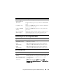
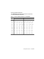
About Your System
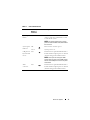
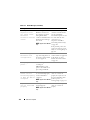
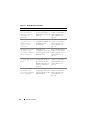
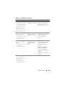
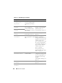
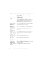
Accessing System Features During Start-up
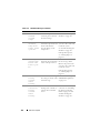
Keystroke
Description
<F2>
Enters the System Setup program. See "Using the System Setup
Program and UEFI Boot Manager" on page 137.
<F10>
Enters System Services, which opens the Dell Unified Server
Configurator (USC). The Dell USC allows you to access utilities such
as embedded system diagnostics. For more information, see the
Unified Server Configurator documentation.
NOTE: Unified Server Configurator is supported on PowerEdge M610,
M610x, M710, M710HD, M910, and M915.
<F11>
Boot Mode set to BIOS: Enters the BIOS Boot Manager, which allows
you to select a boot device.
Boot Mode set to UEFI: Enters the UEFI Boot Manager, which
enables you to manage your system’s boot options.
<F12>
Enters PXE boot (if enabled in System Setup program).
<Ctrl><E> Enters the remote access utility, which allows access to the system
event log (SEL) and configuration of remote access to the system.
<Ctrl><C> Enters the SAS Configuration Utility. See your SAS adapter
documentation for more information.
<Ctrl><R> Enters the RAID configuration utility. For more information, see the
documentation for your RAID card.
<Ctrl><S> Enters the utility to configure NIC settings for PXE boot. For more
information, see the documentation for your integrated NIC.
About Your System
13
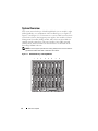
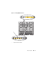
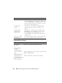
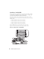
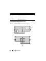
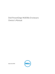
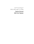
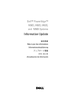
System Overview
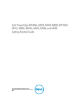
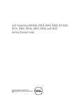
Your system can include up to 16 half-height blades (server modules), eight
full-height blades, or a combination of the two blade types (see Figure 1-1,
Figure 1-2, and Figure 1-3). To function as a system, a blade is inserted into
an enclosure (chassis) that supports power supplies, fan modules, a Chassis
Management Controller (CMC) module, and at least one I/O module for
external network connectivity. The power supplies, fans, CMC, optional
iKVM module, and I/O modules are shared resources of the blades in the
PowerEdge M1000e enclosure.
NOTE: To ensure proper operation and cooling, all bays in the enclosure must be
populated at all times with either a module or with a blank.
Figure 1-1. Blade Numbering – Half-Height Blades
14
1
2
3
4
5
6
7
9
10
11
12
13
14
15
About Your System
8
16
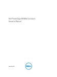
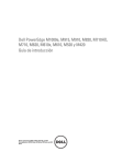
Figure 1-2. Blade Numbering – Full Height Blades
1
2
3
4
5
6
7
8
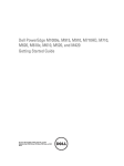
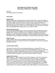
Figure 1-3. Blade Numbering – Mixed Full-Height and Half-Height Blades
1
2
3
4
5
13
6
14
7
8
15
16
About Your System
15
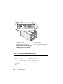
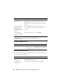
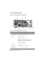
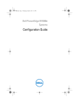
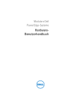
System Control Panel Features
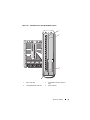
Figure 1-4. Control Panel Features
1
16
3
2
4
5
1
USB port (mouse only)
2
USB port (keyboard only)
3
video connector
4
system power button
5
power indicator
About Your System
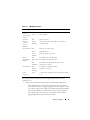
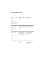
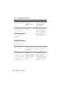
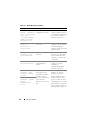
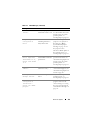
Table 1-1. Control Panel Features
Item
Indicator, Icon
Button, or
Connector
System power N/A
button
Description
Turns the system on and off. Press to turn
on the system. Press and hold 10 seconds
to turn off the system.
NOTE: The system power button controls
power to all of the blades and I/O modules in
the enclosure.
System power Off
indicator
Green
System power is on.
Enclosure does not have power.
USB ports for N/A
keyboard and
mouse
Functional if an optional iKVM module is
installed and front panel ports are enabled
(default setting) in the CMC interface.
NOTE: These ports do not support USB
storage devices. Only connect USB storage
devices to the USB ports on the front panel
of the blade.
Video
connector
N/A
Functional if an optional iKVM module is
installed and front panel ports are enabled
(default setting) in the CMC interface.
About Your System
17
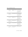
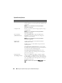
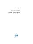
LCD Module
The LCD module provides an initial configuration/deployment wizard, as
well as easy access to infrastructure and blade information, and error
reporting. See Figure 1-5.
Figure 1-5. LCD Display
1
2
3
18
1
LCD screen
3
scroll buttons (4)
About Your System
2
selection ("check") button
LCD Module Features
The primary function of the LCD module is to provide real-time information
on the health and status of the modules in the enclosure.
LCD module features include:
•
A deployment setup wizard that allows you to configure the CMC
module’s network settings during initial system set up.
•
Menus to configure the iDRAC in each blade.
•
Status information screens for each blade.
•
Status information screens for the modules installed in the back of the
enclosure, including the IO modules, fans, CMC, iKVM, and power
supplies.
•
A network summary screen listing the IP addresses of all components in
the system.
•
Real time power consumption statistics, including high and low values,
and average power consumption.
•
Ambient temperature values.
•
AC power information.
•
Critical failure alerts and warnings.
Using the LCD Module Menus
Table 1-2. LCD Module Screen Navigation Keys
Keys
Action
Left and right arrows
Move between screens.
Up arrow or down arrow
Move to the previous or next option on a screen.
Center button
Select and save an item and move to the next
screen.
About Your System
19
Configuration Wizard
The CMC is preset for DHCP. To use a static IP address, you must toggle the
CMC setting from DHCP to a static address by either running the LCD
Configuration Wizard, or by using a management station and CLI
commands. (For more information, see the PowerEdge M1000e Configuration
Guide or CMC documentation.)
NOTE: After you run the configuration wizard, this option is no longer available on
the LCD menus.
1 Choose a language from the options presented in the dialog box.
2 Start the configuration wizard.
3 Configure the CMC network settings for your network environment:
•
Network speed
•
Duplex mode
•
Network mode (DHCP or static)
•
Static IP address, subnet mask, and gateway values (if static mode was
selected)
•
DNS settings
4 If desired, configure the iDRAC network settings.
See the CMC User’s Guide for detailed information about the iDRAC.
NOTE: The configuration wizard automatically configures each blade’s iDRAC
internal network interface if you do not choose to manually configure the
iDRAC settings.
NOTE: You cannot set a static IP address for the iDRAC using the LCD
Configuration Wizard. To set a static IP address, use the CMC Web-based
interface or RACADM.
5 Review the settings on the Network Summary screen.
•
If the settings are correct, press the center button to close the
configuration wizard and return to the Main Menu.
•
If the settings are not correct, use the left arrow key to return to the
screen for that setting and correct it.
After you complete the configuration wizard, the CMC is available on your
network.
20
About Your System
Main Menu
The Main Menu options include links to the LCD Setup Menu, Server
Menu, and Enclosure Menu.
LCD Setup Menu
You can change the default language and start-up screen for the LCD menu
screens using this menu.
Server Menu
From the Server Menu dialog box, you can highlight each blade in the
enclosure using the arrow keys, and view its status.
•
A blade that is powered off or booting is designated by a gray rectangle. An
active blade is indicated by a green rectangle. If a blade has errors, this
condition is indicated by an amber rectangle.
•
To select a blade, highlight it and press the center button. A dialog box
displays the iDRAC IP address of the blade and any errors present.
Enclosure Menu
The Enclosure Menu includes options for Module Status, Enclosure Status,
and Network Summary.
•
In the Module Status dialog box, you can highlight each component in the
enclosure and view its status.
–
A module that is powered off or booting is designated by a gray
rectangle. An active module is indicated by a green rectangle. If a
module has errors, it is indicated by an amber rectangle.
–
If a module is selected, a dialog box displays the current status of the
module and any errors present.
•
In the Enclosure Status dialog box, you can view the enclosure status, any
error conditions, and power consumption statistics.
•
The Network Summary screen lists the IP addresses for the CMC, the
iDRAC in each blade, and other components in the enclosure.
About Your System
21
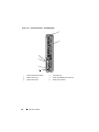
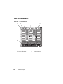
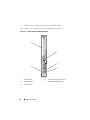
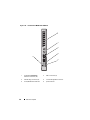
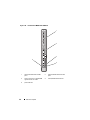
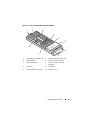
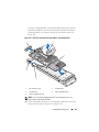
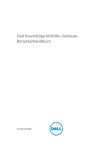
Blade Features
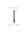
Figure 1-6. Front Panel Features – PowerEdge M915
1
2
6
5
4
3
22
1
blade handle release button
2
hard drives (2)
3
blade status/identification indicator
4
USB connectors (3)
5
blade power button
6
blade power indicator
About Your System
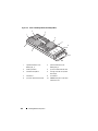
Figure 1-7. Front Panel Features – PowerEdge M910
1
2
6
5
4
3
1
blade handle release button
2
hard drives (2)
3
blade status/identification indicator
4
USB connectors (3)
5
blade power button
6
blade power indicator
About Your System
23
Figure 1-8. Front Panel Features – PowerEdge M905 and M805
1
2
6
5
4
3
24
1
blade handle release button
2
hard drives (2)
3
blade status/identification indicator
4
USB connectors (3)
5
blade power button
6
blade power indicator
About Your System
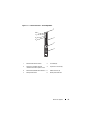
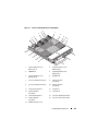
Figure 1-9. Front Panel Features – PowerEdge M710HD
1
6
5
2
4
3
1
blade handle release button
2
hard drives (2)
3
blade status/identification indicator
4
USB connectors (2)
5
blade power button
6
blade power indicator
About Your System
25
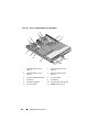
Figure 1-10. Front Panel Features – PowerEdge M710
1
2
6
5
4
3
1
26
blade handle release button
2
hard drives (4)
3
USB connectors (3)
4
blade status/identification indicator
5
blade power button
6
blade power indicator
About Your System
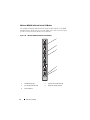
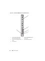
Figure 1-11. Front Panel Features – PowerEdge M610x
1
8
7
2
6
5
3
4
1
blade handle release button
2
hard drive (2)
3
expansion-card filler-bracket
retention latch with captive screw
4
expansion-card slot (2)
5
blade status/identification indicator
6
USB connector (2)
7
blade power button
8
blade power indicator
About Your System
27
Figure 1-12. Front Panel Features – PowerEdge M610
1
6
5
4
3
2
28
1
blade handle release button
2
hard drives (2)
3
blade status/identification indicator
4
USB connectors (2)
5
blade power button
6
blade power indicator
About Your System
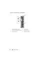
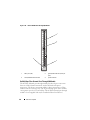
Figure 1-13. Front Panel Features – PowerEdge M605 and M600
1
2
6
5
4
3
1
blade handle release button
2
hard drives (2)
3
blade status/identification indicator
4
USB connectors (2)
5
blade power button
6
blade power indicator
About Your System
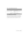
29
Table 1-3. Blade Control Panel Features
Feature
Icon
Blade power
indicator
Description
Off – Power is not available to the blade, the blade is
in standby mode, the blade is not turned on, or the
blade is installed incorrectly. For detailed information
on installing a blade, see "Installing a Blade" on
page 158.
Green increasing from low brightness to full
brightness – Blade power on request is pending.
Green on – The blade is turned on.
Blade status/
identification
indicator
Off – The blade power is off.
Blue – Normal operating state.
Blue blinking – The blade is being remotely
identified using the CMC.
Amber blinking – Blade has either detected an
internal error, or the installed mezzanine card(s) does
not match the I/O modules installed in the M1000e
enclosure. Check the CMC for an I/O configuration
error message and correct the error.
Blade power
button
N/A
Turns blade power off and on.
• If you turn off the blade using the power button
and the blade is running an ACPI-compliant
operating system, the blade can perform an orderly
shutdown before the power is turned off.
• If the blade is not running an ACPI-compliant
operating system, power is turned off immediately
after the power button is pressed.
• Press and hold the button to turn off the blade
immediately.
The blade power button is enabled by default by the
System Setup program.(If the power button option is
disabled, you can only use the power button to turn
on the blade. The blade can then only be shut down
using system management software.)
USB connector
30
About Your System
Connects external USB 2.0 devices to the blade.
Using USB Diskette or USB DVD/CD Drives
Each blade has USB ports on the front of the blade which allows you to
connect a USB diskette drive, USB flash drive, USB DVD/CD drive, keyboard,
or mouse. The USB drives can be used to configure the blade.
NOTE: These blades support only Dell-branded USB 2.0 drives. The drive must be
horizontal and level to operate properly. Use the optional external drive storage tray
to support the drive while in use.
NOTE: If the drive must be designated as the boot drive, connect the USB drive,
restart the system, then enter the System Setup Program and set the drive as first in
the boot sequence (see "Using the System Setup Program and UEFI Boot Manager"
on page 137). The USB device is displayed in the boot order setup screen only if it is
attached to the system before you run the System Setup program.
You can also select the boot device by pressing <F11> during system start-up and
selecting a boot device for the current boot sequence.
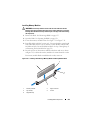
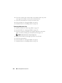
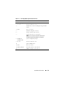
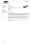
Hard-Drive Features
•
PowerEdge M915 supports two 2.5-inch SAS or solid-state disk (SSD)
hard drives.
•
PowerEdge M910 supports up to two 2.5-inch SAS, SATA, or SSD hard
drives.
•
PowerEdge M905 and M805 support one or two hot-swappable
2.5-inch SAS hard drives.
•
PowerEdge M710HD supports up to two hot-swappable
2.5-inch SAS or SSD hard drives.
•
PowerEdge M710 supports up to four hot-swappable 2.5-inch SAS hard
drives.
•
PowerEdge M610, M610x, M600, and M605 support one or two 2.5-inch
SATA hard drives or one or two 2.5-inch SAS hard drives.
NOTE: SAS and SATA hard drives cannot be mixed within a blade.
NOTE: SATA hard drives are not hot swappable with the SATA repeater
daughter card.
NOTE: Hot-swap drive operation is supported if an optional RAID controller
card is installed in the blade.
About Your System
31
The hard-disk drives plug into the internal storage backplane inside the blade.
On blades with a diskless configuration, all hard drive slots must be filled with
hard drive blanks, and the internal storage backplane must still be installed to
maintain proper airflow.
See Figure 1-14 for information on the hard-drive indicators. Different
patterns are displayed as drive events occur in the system.
NOTE: The blade must have a hard drive or a hard-drive blank installed in each
hard-drive bay.
NOTE: The hard-drive status indicator is only functional for RAID hard drive
configurations. For non-RAID configurations, only the drive-activity indicator is
active. Refer to the RAID controller documentation to service a RAID volume,
rebuild an array, or swap RAID members.
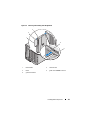
Figure 1-14. Hard-Drive Indicators
2
1
1
32
drive-activity indicator (green)
About Your System
2
drive-status indicator (green and
amber)
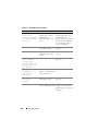
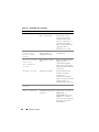
Table 1-4. Hard-Drive Indicators
Condition
Drive-Status Indicator Pattern
Identifying drive/preparing Blinks green two times per second
for removal
Drive ready for insertion or Off
removal
NOTE: The drive status indicator remains off until all
hard drives are initialized after system power is applied.
Drives are not ready for insertion or removal during this
time.
Drive predicted failure
Blinks green, amber, and off.
Drive failed
Blinks amber four times per second.
Drive rebuilding
Blinks green slowly.
Drive online
Steady green.
Rebuild halted
Blinks green three seconds, amber three seconds, and
off six seconds.
About Your System
33
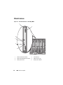
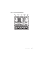
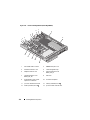
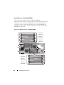
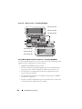
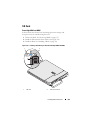
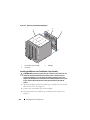
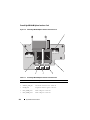
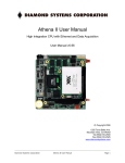
Back-Panel Features
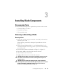
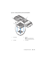
Figure 1-15. Back-Panel Features
1
2
3
4
5
6
34
1
fan modules (9)
2
primary CMC module
3
I/O modules (6)
4
optional iKVM module
5
secondary CMC module
6
power supplies (6)
About Your System
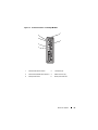
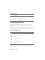
Figure 1-16. Back-Panel Module Bay Numbering
CMC 1
A1 B1 C1
C2 B2 A2
iKVM
CMC 2
1
2
3
4
5
6
7
8
9
1
2
2 3
4
5
6
About Your System
35
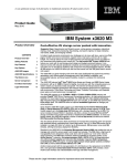
Power Supply Indicator
NOTE: The power supplies must be connected to a PDU, not directly to an
electrical outlet.
•
The power supplies require a 200-240 V power source.
•
A 2700 W power supply can be connected to a 110 V AC power source.
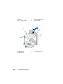
Figure 1-17. Power Supply Indicators
1
2
3
36
1
DC power output indicator
3
AC power present indicator
About Your System
2
power supply fault indicator
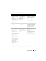
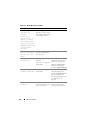
Table 1-5. Power Supply Indicators
Indicator
Icon
Description
Power supply
status
Green indicates that the power supply is operational and
providing DC power to the system.
Fault indicator
Amber indicates a problem with the power supply, which
can result from either a failed power supply or a failed fan
within the power supply. See "Power Supply Modules."
AC power source
present indicator
Green indicates that a valid AC source is connected to the
power supply and is operational.
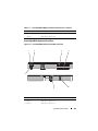
Fan Module Indicators
Figure 1-18. Fan Module Indicators
1
2
1
fan power indicator
2
fan fault indicator
About Your System
37
Table 1-6. Fan Indicators
Indicator
Indicator Description
State
Power indicator Green
Fault indicator
The power supply is connected to an AC power source.
Off
AC power not connected.
Amber
The fan is in a fault condition.
Off
Fan not faulty.
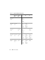
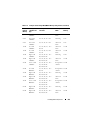
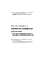
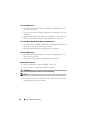
Identifying Midplane Version
The version of the midplane installed in the enclosure is displayed in the
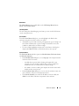
Midplane Revision field under the Summary tab of the CMC Web-based
interface.
You can also view the icons at the back of the enclosure to identify the version
of the midplane installed in the system. Table 1-7 describes the icons at the
back of the enclosure.
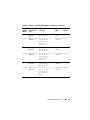
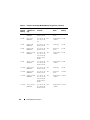
Table 1-7. Identifying Midplane Version
Marking
Description
Midplane Version
I/O module slots A1, A2
1.1
I/O module slots B1, B2, C1,
1.1
I/O module slots A1, A2
1.0
I/O module slots B1, B2, C1,
1.0
and C2
and C2
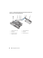
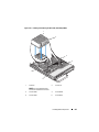
See Figure 1-19 and Figure 1-20 to locate the midplane identification labels
on the enclosure.
38
About Your System
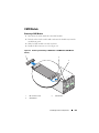
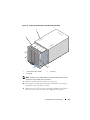
Figure 1-19. Identifying Midplane Version 1.1
1
1
midplane identification label (2)
About Your System
39
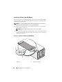
Figure 1-20. Identifying Midplane Version 1.0
1
1
40
midplane identification label (2)
About Your System
iKVM Module
The optional Avocent iKVM analogue switch module includes the following
features:
•
Local iKVM access can be remotely disabled on a per blade basis, using the
blade’s iDRAC interface (access is enabled by default).
NOTE: By default (enabled), a console session to a given blade is available to
both the iDRAC interface and iKVM (users connected to a blade's console
using iDRAC and the iKVM sees the same video and is able to type
commands). If this sharing is not desired, this can be disabled using the iDRAC
console interface.
•
The following connectors:
–
One VGA connector. The iKVM supports a video display resolution
range from 640×480 at 60 Hz up to 1280×1024×65,000 colors
(noninterlaced) at 75 Hz.
–
Two USB ports for keyboard and mouse.
–
RJ-45 ACI port for tiering with Dell and Avocent analog KVM and
KVM over IP switches with ARI ports.
NOTE: The iKVM USB ports do not support storage devices.
NOTE: Although the ACI port is an RJ-45 connector and uses Cat5 (or better)
cabling, it is not an Ethernet network interface port. It is only used for
connection to external KVM switches with Analog Rack Interface (ARI) ports,
and does not support native KVM over IP.
•
The iKVM can also be accessed from the front of the enclosure, providing
front or back panel KVM functionality, but not at the same time. For
enhanced security, front panel access can be disabled using the CMC’s
interface.
NOTE: Connecting a keyboard, video, and mouse to the enclosure front panel
disables video output to the iKVM back panel port. It does not interrupt iDRAC
video and console redirection.
•
You can use the iKVM to access the CMC console directly, using
RACADM or using the Web-based interface. For more information, see
"Using the iKVM Module" in the CMC User’s Guide.
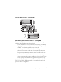
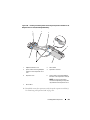
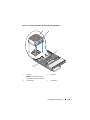
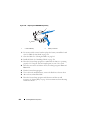
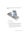
Figure 1-21 shows the external features of the iKVM switch module.
About Your System
41
Figure 1-21. Avocent iKVM Switch Module
1
2
3
4
5
1
identification indicator
2
status indicator
3
ACI port for tiering connection only
4
USB connectors (2) for keyboard
and mouse
CAUTION: Do not connect the ACI port to
a LAN device such as a network hub.
Doing so may result in equipment damage.
5
video connector
Table 1-8. Avocent Analog iKVM Switch Module Features
Feature
Indicator Pattern
Description
Power
indicator
Off
iKVM switch does not have power.
Green
iKVM switch has power.
Green flashing
Firmware upgrade in progress
Status/
Blue blinking
identification
Amber flashing
indicator
42
About Your System
iKVM module is being identified.
System fault or error condition.
Table 1-8. Avocent Analog iKVM Switch Module Features
Feature
Indicator Pattern
Description
USB
connectors
Allows a keyboard and mouse to be connected to
the system.
Video
connector
Allows a monitor to be connected to the system.
ACI port
Allows connection of one or more servers to a
Dell console switch with an Analog Rack
Interface (ARI) port, such as an external digital
or analog switch.
Link indicator Off
The ACI is not connected to the external switch.
Activity
indicator
Green
The ACI is connected to the external switch.
Off
Data is not being sent or received.
Amber blinking
Data is being sent or received.
About Your System
43
Tiering the Avocent iKVM Switch From an Analog KVM Switch
The Avocent iKVM switch can be tiered from analog KVM switches such as
the Dell 2160AS and 180AS, as well as many Avocent analog KVM switches.
Many switches may be tiered without the need for a Server Interface Pod
(SIP) (see Table 1-9).
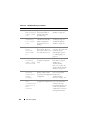
Table 1-9. Cabling Requirements for External Analog KVM Switches
Switch
Tiering Cabling Requirements
Seamless tiering using ACI port and Cat 5
Avocent Autoview 1400, 1500, 2000, cable
2020, 2030, Ax000R
Dell PowerConnect 180AS, 2160AS
Avocent Autoview 200, 400, 416, 424 Dell USB SIP required with Cat 5 cable
Avocent Outlook 140ES, 180ES,
160ES
Before connecting the iKVM switch to a supported analog switch, you must
set the iKVM switch to display in slot order, and set the Screen Delay Time to
1 or more seconds:
1 Press <Print Screen> to launch the iKVM Switch OSCAR.
The OSCAR dialog box appears on the monitor connected to the iKVM.
2 Click SetupMenu. The Menu dialog box appears.
3 Select Slot to display servers numerically by slot number.
4 Enter a screen delay time of at least 1 second.
5 Click OK.
Setting the Screen Delay Time to 1 second allows you to soft switch to a
server without launching OSCAR.
NOTE: Soft switching allows you to switch servers using a hot key sequence. You
can soft switch to a server by pressing <Print Screen> and then typing the first few
characters of its name or number. If you have a Delay Time set and you press the
key sequences before that time has elapsed, OSCAR does not display.
44
About Your System
To configure the analog switch:
1 Press <Print Screen> to open the OSCAR Main dialog box.
2 Click Setup DevicesDevice Modify.
3 Select the 16-port option to match the number of blades in your system.
4 Click OK to exit OSCAR.
5 Press <Print Screen> to verify that the settings have taken effect. The slot
number of the blade to which the iKVM switch is now attached should be
expanded to display each of the slot locations of the blades in the system.
For instance, if the iKVM switch is attached to slot 1, it would now be
displayed as 01-01 to 01-16.
To connect the Avocent iKVM switch to a supported analog switch:
1 If the switch does not require a SIP to connect to the iKVM (see Table 1-9),
connect a Cat5 (or newer) cable to the RJ-45 ACI port on the iKVM
module. See Figure 1-21.
Connect the other end of this cable to the ARI port on the external switch.
If the analog switch requires a USB SIP (see Table 1-9), connect a USB SIP
to the iKVM, then connect a Cat5 (or newer) cable to the SIP. Connect the
other end of this cable to the ARI port on the external switch.
2 Connect both the analog switch and the system to an appropriate power
source.
3 Turn on the system.
4 Turn on the external analog switch.
NOTE: If the external analog switch is turned on before the system, it may result in
only one blade displaying in the analog switch OSCAR, instead of 16. If this behavior
occurs, shut down and restart the switch so that the entire complement of blades is
recognized.
NOTE: In addition to the steps outlined above, some external analog switches may
require you to perform additional steps to ensure that the iKVM switch blades
appear in the external analog switch OSCAR. See the external analog switch
documentation for more information.
About Your System
45
Tiering the Avocent iKVM Switch From a Digital KVM Switch
The iKVM switch may also be tiered from a digital KVM switch such as the
Dell 2161DS or 4161DS, or a supported Avocent digital KVM switch. Many
switches may be tiered without the need for a SIP (see Table 1-10).
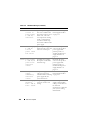
Table 1-10. Cabling Requirements for External Digital KVM Switches
Switch
Tiering Requirements
Dell PowerConnect 2161DS, 4161DS
Seamless tiering using ACI port and Cat 5
cable
Avocent DSR 800, x16x, x010, x031,
x030, x035,102x (except 1024)
Avocent DSR 1024
Dell USB SIP required with Cat 5 cable
To tier the iKVM switch module from a Dell 2161DS, 180AS, or 2160AS
console switch:
•
If the switch does not require a SIP to connect to the iKVM (see Table 1-10),
connect a Cat5 (or newer) cable to the RJ-45 ACI port on the iKVM
module. See Figure 1-21.
Connect the other end of this cable to the ARI port on the external switch.
•
If the switch requires a USB SIP (see Table 1-9), connect a USB SIP to the
iKVM, then connect a Cat5 (or newer) cable to the SIP. Connect the other
end of this cable to the ARI port on the external switch.
Once the KVM switch is connected, the server modules appear in OSCAR.
NOTE: Once the local system is set up, you must also resynchronize the server list
from the Remote Console Switch software in order to see the list of blades. See
Resynchronizing the Server List at the Remote Client Workstation.
46
About Your System
Resynchronizing the Server List at the Remote Client Workstation
Once the iKVM switch is connected, the blades appear in OSCAR. You now
need to resynchronize the servers on any remote workstation to ensure that
the blades are available to any remote users connected to the console switch
through the Remote Console Switch software.
NOTE: This procedure only resynchronizes one remote client workstation. With
multiple client workstations, save the resynchronized local database and load it into
the other client workstations to ensure consistency.
To resynchronize the server listing:
1 Click Resync in the Server category of the Management Panel (MP).
The Resync Wizard launches.
2 Click Next.
A warning message displays indicating that the database is updated to
match the current configuration of the console switch. Your current local
database names may be overridden with the switch names. To include
unpowered SIPs in the resynchronization, click to enable the Include
Offline SIPs check-box.
3 Click Next.
A Polling Remote Console Switch message box appears with a progress
bar indicating that the switch information is being retrieved.
4 If no changes were detected in the appliance, a completion dialog box
appears with this information.
If server changes were detected, then the Detected Changes dialog box is
displayed. Click Next to update the database.
5 If a cascade switch was detected, the Enter Cascade Switch Information
dialog box appears. Select the type of switch connected to the appliance
from the drop-down list. If the type you are looking for is not available, you
can add it by clicking Add.
6 Click Next. The completion dialog box appears.
7 Click Finish to exit.
8 Start up the analog switch and the system.
About Your System
47
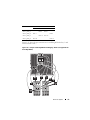
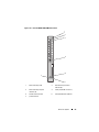
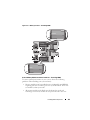
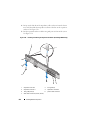
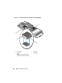
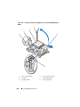
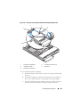
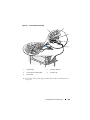
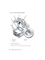
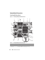
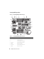
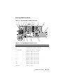
CMC Module
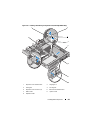
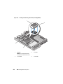
Figure 1-22. CMC Module Features
1
2
3
4
5
10
9
8
6
7
48
1
Ethernet connector Gb1
2
link indicator (2)
3
Ethernet connector STK ("stack") used for daisy-chaining CMCs in
separate enclosures
4
activity indicator (2)
5
DB-9 serial connector for local
configuration
6
optional secondary CMC (CMC 2)
7
primary CMC (CMC 1)
8
amber fault indicator
9
blue status/identification indicator
10
power indicator
About Your System
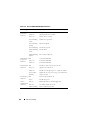
Table 1-11.
CMC Module Features
Indicator
Pattern
Description
Network
interface
controller link
indicator
Off
LAN is not linked.
Green
LAN is linked.
Network
interface
controller
activity
indicator
Off
LAN is not active.
Amber
blinking
Indicates that the system CMC and the LAN are
communicating.
Power indicator Off
Status/
identification
indicator
Green
CMC has power.
Green
blinking
Firmware update in progress.
Off
This CMC is the standby CMC.
Blue (solid) This CMC is the primary CMC.
Blue
(blinking)
Fault indicator Off
Serial
connector
CMC does not have power.
The CMC is being identified by the systems
management software.
The CMC is operating normally.
Amber
blinking
A fault has occurred.
None
Used for local configuration (115200 baud, No parity,
8, 1)
The CMC provides multiple systems management functions for your
modular server:
•
Enclosure-level real-time automatic power and thermal management.
–
The CMC monitors system power requirements and supports the
optional Dynamic Power Supply Engagement mode so that the CMC
can enable or place power supplies in standby dynamically depending
on load and redundancy requirements to improve power efficiency.
–
The CMC reports real-time power consumption, which includes
logging high and low points with a time stamp.
About Your System
49
•
–
The CMC supports setting an optional enclosure Maximum Power
Limit, which either alerts or takes actions, such as throttling server
modules and/or preventing the power up of new blades to keep the
enclosure under the defined maximum power limit.
–
The CMC monitors and automatically controls cooling fans based on
actual ambient and internal temperature measurements.
–
The CMC provides comprehensive enclosure inventory and
status/error reporting.
The CMC provides a mechanism for centralized configuration of the
following:
–
The M1000e enclosure’s network and security settings
–
Power redundancy and power ceiling settings
–
I/O switches and iDRAC network settings
–
First boot device on the server blades
–
The CMC checks I/O fabric consistency between the I/O modules and
blades and disables components if necessary to protect the system
hardware.
–
User access security.
The CMC has two Ethernet ports: Gb1 is used to connect to the external
management network. The connector labeled STK ("stack") allows CMCs in
adjacent enclosures to be daisy-chained. A 24-port Ethernet switch provides
internal communication between the iDRAC on each blade, I/O modules,
optional KVM, and optional second, redundant CMC.
NOTE: The 24-port Ethernet switch is reserved for internal communication
between the iDRAC on the blades to the CMC and the external management
network. If two CMCs are installed, the heartbeat for CMC redundancy is also
present and CMC redundancy is supported over this internal network. This internal
network is outside the data path from host LOMs and the mezzanine cards in the
blades.
At least one CMC must be installed in the primary CMC bay (see
Figure 1-22) for the system to power up. If a second, optional CMC module is
installed, failover protection and hot-plug replacement is available.
See the latest Dell Chassis Management Controller User's Guide at
support.dell.com/manuals for complete instructions on how to set up and
operate the CMC module.
50
About Your System
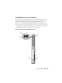
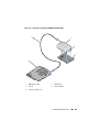
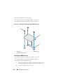
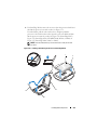
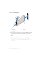
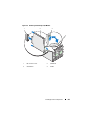
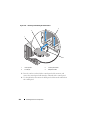
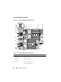
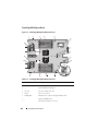
Figure 1-23. CMC Daisy-Chaining
1
2
3
1
management network
3
primary CMC
2
secondary CMC
About Your System
51
I/O Connectivity
The M1000e enclosure supports three layers of I/O fabric, selectable between
combinations of Ethernet, fibre-channel, and Infiniband modules. You can
install up to six hot-swappable I/O modules in the enclosure, including fibrechannel switches, fibre-channel pass-throughs, Infiniband switches, Ethernet
switches, and Ethernet pass-through modules.
Guidelines for Installing I/O Modules
You must follow these guidelines when populating I/O modules. See
Figure 1-15 for the I/O bay locations.
General I/O Module Configuration Guidelines
•
If an I/O module is installed in Fabric B or Fabric C, at least one blade
must have a matching mezzanine card installed to support data flow for
that I/O module.
•
If a blade has an optional mezzanine card installed in a Fabric B or Fabric
C card slot, at least one corresponding I/O module must be installed to
support data flow for that fabric.
•
Modules may be installed in Fabrics B and C independently (you do not
need to install modules in Fabric B before installing modules in the Fabric
C slots.)
•
Slots A1 and A2 only support Ethernet I/O modules. This fabric type is
hard-set to Ethernet for these slots and cannot support Fibre Channel,
Infiniband, or other fabric type modules.
•
Fabrics A, B, and C can support Ethernet fabric-type modules.
•
To enable switch configuration prior to blade imaging, I/O modules are
allowed to power-up before a blade is inserted in the enclosure.
Fabric A
Fabric A is a redundant Gb Ethernet fabric, supporting I/O module slots A1
and A2. The integrated Ethernet controllers in each blade dictate Fabric A as
an Ethernet-only fabric.
NOTE: Fabric A supports KR (10 Gbps standard) if the midplane version in the
enclosure is 1.1 or later. To identify the midplane version, see "Identifying Midplane
Version" on page 38.
52
About Your System
NOTE: Modules designed specifically for Fabric B or Fabric C cannot be installed in
slots A1 or A2, as indicated by the color-coded labeling on the faceplate of each
module.
Fabric B
Fabric B is a 1 to 40 Gb/sec redundant fabric, supporting I/O module slots B1
and B2. Fabric B currently supports 1 Gb or10 Gb Ethernet, DDR/QDR
Infiniband, and 4 Gbps or 8 Gbps Fibre Channel modules. Additional fabric
types may be supported in the future.
NOTE: If the midplane version in the enclosure is 1.1 or later, Fabric B supports up
to 16 Gbps Fibre Channel, Infiniband FDR (14 Gbps standard), and KR (10 Gbps
standard). To identify the midplane version, see "Identifying Midplane Version" on
page 38.
To communicate with an I/O module in the Fabric B slots, a blade must have
a matching mezzanine card installed in a Fabric B mezzanine card location.
Modules designed for Fabric A may also be installed in the Fabric B slots.
Fabric C
Fabric C is a 1 to 40 Gb/sec redundant fabric, supporting I/O module slots C1
and C2. Fabric C currently supports 1 Gb or10 Gb Ethernet, DDR/QDR
Infiniband, and 4 Gbps or 8 Gbps Fibre Channel modules. Additional fabric
types may be supported in the future.
NOTE: If the midplane version in the enclosure is 1.1 or later, Fabric C supports up
to 16 Gbps Fibre Channel, Infiniband FDR (14 Gbps standard), and KR (10 Gbps
standard). To identify the midplane version, see "Identifying Midplane Version" on
page 38.
To communicate with an I/O module in the Fabric C slots, a blade must have
a matching mezzanine card installed in a Fabric C mezzanine card location.
Modules designed for Fabric A may also be installed in the Fabric C slots.
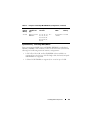
Port Auto-Disablement in Quad-Port Network Daughter Card
(PowerEdge M710HD Only)
Systems installed with quad-port Network Daughter Card support Port AutoDisablement feature. This feature disables the third (NIC3) and fourth
(NIC4) ports of a quad-port Network Daughter Card during system boot, if
the corresponding IO module installed in the chassis Fabric A slots do not
About Your System
53
support quad-port mapping. This behavior is limited to Fabric A slots only
and is automatically enabled or disabled depending on the type of IO module
installed.
NOTE: A quad-port Network Daughter Card must be used with a 48-port switch
module (32 internal ports) for all the ports to be active.
NOTE: LOM firmware updates are applied only to the enabled ports on a quad-port
network daughter card.
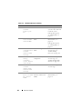
Table 1-12 provides an overview of the configurations that enable/disable the
NIC3 and NIC4 ports of a quad-port Network Daughter Card.
Table 1-12. Port Auto-Disablement Decision Table
IOM Slot A1
IOM Slot A2
NIC3 and NIC4
(Enabled/Disabled)
Port AutoDisablement
Empty
Empty
Enabled
Inactive
Empty
Dual Port
Disabled
Active
Empty
Quad or Greater
Port
Enabled
Inactive
Dual Port
Empty
Disabled
Active
Dual Port
Dual Port
Disabled
Active
Dual Port
Quad or Greater
Port
Enabled
Inactive
Quad or Greater
Port
Empty
Enabled
Inactive
Quad or Greater
Port
Dual Port
Enabled
Inactive
Quad or Greater
Port
Quad or Greater
Port
Enabled
Inactive
54
About Your System
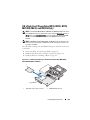
Mezzanine Cards
PowerEdge M610x Only
PowerEdge M610x supports two mezzanine cards. Mezzanine cards can be
installed in both the slots on the midplane interface card.
NOTE: PowerEdge M610x is a full-height blade but supports only two mezzanine
cards in the expansion bay. The two mezzanine slots on the M610x system board
(MEZZ2_FAB_B and MEZZ1_FAB_C) are reserved for the mezzanine interface card.
See "Mezzanine Interface Card (PowerEdge M610x Only)" on page 215.
Full-Height Blades
Full-height blades support four mezzanine cards:
•
Slot Mezz1_Fabric_C and slot Mezz3_Fabric_C support Fabric C. They
must match the fabric type of the I/O modules installed in I/O module
slots C1 and C2.
•
Slot Mezz2_Fabric_B and slot Mezz4_Fabric_B support Fabric B. They
must match the fabric type of the I/O modules installed in I/O module
slots B1 and B2.
Half-Height Blades
Half-height blades support two mezzanine cards:
•
Mezzanine card slot C supports Fabric C. This card must match the fabric
type of I/O modules installed in I/O module slots C1 and C2.
•
Mezzanine card slot B supports Fabric B. This card must match the fabric
type of I/O modules installed in I/O module slots B1 and B2.
See "I/O Module Mezzanine Cards" on page 217 for more information on
mezzanine cards.
Table 1-13 shows various supported combinations of mezzanine cards and I/O
modules.
About Your System
55
Table 1-13. Supported I/O Module Configurations
Fabric A
Fabric B
Mezzanine
Card
Fabric C
Mezzanine
Card
I/O Bay A1,
A2
I/O Bay B1,
B2
I/O Bay C1,
C2
Standard
Integrated
LOM
none
none
Ethernet
switch
module or
passthrough
module
none
none
Standard
Integrated
LOM
Ethernet
mezzanine
card
none
Ethernet
switch
module or
passthrough
module
Ethernet
switch
module or
passthrough
module
none
Standard
Integrated
LOM
none
Infiniband
mezzanine
card
Ethernet
switch
module or
passthrough
module
none
Infiniband
switch
module
Standard
Integrated
LOM
Ethernet
mezzanine
card
Ethernet
mezzanine
card
Ethernet
switch
module or
passthrough
module
Ethernet
switch
module or
passthrough
module
Ethernet
switch
module or
passthrough
module
Standard
Integrated
LOM
Fibre
Channel
mezzanine
card
Infiniband
mezzanine
card
Ethernet
switch
module or
passthrough
module
Fibre
Channel
switch or
passthrough
module
Infiniband
switch
module
56
About Your System
Table 1-13.
Supported I/O Module Configurations (continued)
Fabric A
Fabric B
Mezzanine
Card
Fabric C
Mezzanine
Card
I/O Bay A1,
A2
I/O Bay B1,
B2
I/O Bay C1,
C2
Standard
Integrated
LOM
none
Fibre
Channel
mezzanine
card
Ethernet
switch
module or
passthrough
module
none
Fibre
Channel
switch
module or
passthrough
module
Standard
Integrated
LOM
Fibre
Channel
mezzanine
card
Fibre
Channel
mezzanine
card
Ethernet
switch
module or
passthrough
module
Fibre
Channel
switch or
passthrough
module
Fibre
Channel
switch or
passthrough
module
Standard
Integrated
LOM
Ethernet
mezzanine
card
Fibre
Channel
mezzanine
card
Ethernet
switch
module or
passthrough
module
Ethernet
switch
module or
passthrough
module
Fibre
Channel
switch or
passthrough
module
Standard
Integrated
LOM
Infiniband
mezzanine
card
Infiniband
mezzanine
card
Ethernet
switch
module or
passthrough
module
Infiniband
switch
module
Infiniband
switch
module
Standard
Integrated
LOM
Infiniband
mezzanine
card
Ethernet
mezzanine
card
Ethernet
switch
module or
passthrough
module
Infiniband
switch
module
Ethernet
switch
module or
passthrough
module
About Your System
57
Table 1-13. Supported I/O Module Configurations (continued)
Fabric A
Fabric B
Mezzanine
Card
Fabric C
Mezzanine
Card
I/O Bay A1,
A2
I/O Bay B1,
B2
I/O Bay C1,
C2
Standard
Integrated
LOM
Fibre
Channel
mezzanine
card
Ethernet
mezzanine
card
Ethernet
switch
module or
passthrough
module
Fibre
Channel
switch or
passthrough
module
Ethernet
switch
module or
passthrough
module
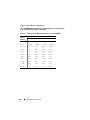
I/O Module Port Mapping
The LOM and optional mezzanine cards are mapped to the I/O module ports
based on the following rules.
NOTE: The I/O port mappings in the following sections are applicable only to the
I/O Pass-Through Modules.
Full-Height Blades
Standard LOM (Dual-Port) Mapping
Each LOM has two port connections. For a full-height blade in bay n:
•
Integrated LOM1, connection 1 connects to I/O module A1, port n.
Integrated LOM1, connection 2 connects to I/O module A2, port n.
•
Integrated LOM2, connection 1 connects to I/O module A1, port n+8.
Integrated LOM2, connection 2 connects to I/O module A2, port n+8.
For example, in a full-height blade in slot 5, integrated LOM1 connection 1
connects to I/O module A1, port 5 and LOM1 connection 2 connects to I/O
module A2 port 5. LOM2 connection 1 connects to I/O module A1, port 13
and LOM2 connection 2 connects to I/O module A2, port 13.
NOTE: Even though PowerEdge M610x is a full-height blade system, only one
network controller (LOM1) is available.
For PowerEdge M610x blade in bay n:
•
58
The integrated NIC connects to I/O module A1, port n and I/O module
A2, port n
About Your System
Dual-Port Mezzanine Cards
Each mezzanine card has two port connections. For a full-height blade in bay
n:
•
Mezzanine card 1, connection 1 connects to I/O module C1, port n.
Mezzanine card 1, connection 2 connects to I/O module C2, port n.
•
Mezzanine card 2, connection 1 connects to I/O module B1, port n.
Mezzanine card 2, connection 2 connects to I/O module B2 port n.
•
Mezzanine card 3, connection 1 connects to I/O module C1, port n+8.
Mezzanine card 3, connection 2 connects to I/O module C2 port n+8.
•
Mezzanine card 4, connection 1 connects to I/O module B1, port n+8.
Mezzanine card 4, connection 2 connects to I/O module B2 port n+8.
For example, in a full-height blade mezzanine card 3, connection 1 connects
to I/O module C1, port 13 and Mezzanine card 3, connection 2 connects to I/O
module C2 port 13. Table 1-15 shows the port number assignments for the
eight possible full height blade locations.
NOTE: Even though PowerEdge M610x is a full blade system, only two mezzanine
card slots (MEZZ1_Fab_C1 and MEZZ2_FAB_B1) in the expansion bay are available
for use. The other two slots on the system board (MEZZ1_FAB_C and
MEZZ2_FAB_B) are occupied by the mezzanine interface card which provides
connectivity between the PCIe expansion-card riser and the system board.
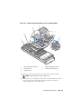
For PowerEdge M610x in bay n:
•
Mezzanine card B (in the expansion bay) connects to I/O module B1, port
n+8 and I/O module B2, port n+8.
•
Mezzanine card C (in the expansion bay) connects to I/O module C1, port
n+8 and I/O module C2, port n+8.
Table 1-14.
Example of I/O Module Port Assignments - PowerEdge M610x in Slot 2
Blade 2
I/O Module
A1
B1
Mezzanine
Card C
Mezzanine
Card B
Port 10
C1
C2
B2
Port 10
Port 10
A2
Port 10
About Your System
59
Figure 1-24. Example of PowerEdge M610x Port Mapping of – Blade 2
60
About Your System
Table 1-15. I/O Module Port Assignments - Full-Height Blades (not applicable for
PowerEdge M610x)
Blade 1
I/O Module
B1
Mezz1_Fab_C
Mezz2_Fab_B
Port 1
Port 9
Port 9
C1
C2
Port 2
Port 2
Port 2
Mezz3_Fab_C
B2
Port 2
Port 10
Port 10
Port 10
Blade 3
Port 10
I/O Module
B1
Mezz1_Fab_C
C1
C2
Port 3
Port 3
Port 3
Mezz3_Fab_C
Mezz4_Fab_B
B2
I/O Module
Mezz1_Fab_C
Mezz2_Fab_B
Port 1
Port 9
B1
Mezz4_Fab_B
Port 1
Port 9
Blade 2
Mezz2_Fab_B
C2
Port 1
Mezz3_Fab_C
Mezz4_Fab_B
C1
Port 3
Port 11
Port 11
B2
Port 11
Port 11
About Your System
61
Blade 4
I/O Module
B1
Mezz1_Fab_C
Mezz2_Fab_B
Port 4
Port 4
B2
Port 4
Port 12
Port 12
Port 12
Blade 5
Port 12
I/O Module
B1
Mezz1_Fab_C
Mezz2_Fab_B
Mezz4_Fab_B
C1
C2
Port 5
Port 5
Port 5
Mezz3_Fab_C
B2
Port 5
Port 13
Port 13
Port 13
Blade 6
Port 13
I/O Module
B1
Mezz1_Fab_C
Mezz2_Fab_B
Mezz4_Fab_B
C1
C2
Port 6
Port 6
Port 6
Mezz3_Fab_C
B2
Port 6
Port 14
Port 14
Port 14
Blade 7
Port 14
I/O Module
B1
Mezz1_Fab_C
Mezz2_Fab_B
Mezz4_Fab_B
C1
C2
Port 7
Port 7
Port 7
Mezz3_Fab_C
62
C2
Port 4
Mezz3_Fab_C
Mezz4_Fab_B
C1
Port 7
Port 15
Port 15
About Your System
B2
Port 15
Port 15
Blade 8
B1
Mezz1_Fab_C
Mezz2_Fab_B
V
C1
C2
B2
Port 8
Port 8
Port 8
Mezz3_Fab_C
Mezz4_Fab_B
I/O Module
Port 8
Port 16
Port 16
Port 16
Port 16
Figure 1-25 shows the port connections for a full-height blade in bay 3 with
four mezzanine cards.
Figure 1-25. Example of Full-Height Blade Port Mapping – Blade 3 (not applicable for
PowerEdge M610x)
About Your System
63
Quad-Port Mezzanine Cards
Table 1-16 illustrates the I/O module port mapping for full-height blades with
quad-port mezzanine cards.
NOTE: For a detailed mapping of each PowerEdge system, see the document
Quadport Capable Hardware for the M1000e Modular Chassis on
support.dell.com/manuals.
Table 1-16. I/O Module Port Assignments—Full-Height Blades (not applicable for
PowerEdge M610x)
Blade n and Blade (n + 8)
NOTE: n denotes a variable
value from 1 to 8.
I/O Module
B1
C1
C2
B2
Mezz_FAB_B_Blade n_Port1 Port n
Mezz_FAB_B_Blade n_Port2
Port n
Mezz_FAB_B_Blade n_Port3 Port
(n+16)
Mezz_FAB_B_Blade n_Port4
Port
(n+16)
Mezz_FAB_C_Blade n_Port1
Port n
Mezz_FAB_C_Blade n_Port2
Port n
Mezz_FAB_C_Blade n_Port3
Port
(n+16)
Mezz_FAB_C_Blade n_Port4
Mezz_FAB_B_Blade
n+8_Port1
Port
(n+16)
Port
(n+8)
Mezz_FAB_B_Blade
n+8_Port2
Mezz_FAB_B_Blade
n+8_Port3
Port
(n+8)
Port
(n+24)
Mezz_FAB_B_Blade
n+8_Port4
Mezz_FAB_C_Blade
n+8_Port1
64
About Your System
Port
(n+24)
Port
(n+8)
Table 1-16. I/O Module Port Assignments—Full-Height Blades (continued)(not
applicable for PowerEdge M610x)
Blade n and Blade (n + 8)
NOTE: n denotes a variable
value from 1 to 8.
I/O Module
B1
C1
Mezz_FAB_C_Blade
n+8_Port2
C2
B2
Port
(n+8)
Mezz_FAB_C_Blade
n+8_Port3
Port
(n+24)
Mezz_FAB_C_Blade
n+8_Port4
Port
(n+24)
NOTE: Even though PowerEdge M610x is a full blade system, only two mezzanine
card slots (MEZZ1_Fab_C1 and MEZZ2_FAB_B1) in the expansion bay are available
for use. The other two slots on the system board (MEZZ1_FAB_C and
MEZZ2_FAB_B) are occupied by the mezzanine interface card which provides
connectivity between the PCIe expansion-card riser and the system board.
Table 1-17 illustrates the I/O module port mapping for PowerEdge M610x
in bay n.
Table 1-17.
Example of I/O Module Port Assignments - PowerEdge M610x Blade 1
Blade 1
I/O Module
A1
B1
C1
C2
B2
Mezzanine
Card C (port 1
and port 2)
Port 9
Port 9
Mezzanine
Card C (port
3and port 4)
Port 25
Port 25
Mezzanine
Card B (port 1
and port 2)
Port 9
Port 9
Mezzanine
Card B (port 1
and port 2)
Port 25
Port 25
A2
About Your System
65
Half-Height Blades
Standard LOM (Dual-Port) and Network Daughter Card (Quad-Port) Mapping
Each standard LOM has two port connections. For a half-height blade
in bay n:
•
Integrated LOM, connection 1 connects to I/O module A1, port n.
Integrated LOM, connection 2 connects to I/O module A2, port n.
Half-height blades with Network Daughter Card (PowerEdge M710HD)
hosts two network controllers (LOM1 and LOM2), each with two port
connections. For a half-height blade in bay n:
•
LOM1, connection 1 connects to I/O module A1, port n.
LOM1, connection 2 connects to I/O module A2, port n.
•
LOM2, connection 1 connects to I/O module A1, port n+16.
LOM2, connection 2 connects to I/O module A2, port n+16.
NOTE: If the I/O modules A1 and A2 are not quad-port capable, then the LOM2
ports (NIC3 and NIC4) gets disabled during system boot. For more information, see
"Port Auto-Disablement in Quad-Port Network Daughter Card (PowerEdge M710HD
Only)" on page 53.
For example, in a half-height blade in slot 5, integrated LOM1 connection 1
connects to I/O module A1, port 5 and LOM1 connection 2 connects to I/O
module A2, port 5. LOM2 connection 1 connects to I/O module A1, port 21
and LOM2 connection 2 connects to I/O module A2, port 21.
Dual-Port Mezzanine Cards
For a half-height blade in bay n:
•
The integrated NIC connects to I/O module A1, port n and I/O module
A2, port n.
•
Mezzanine card B connects to I/O module B1, port n and I/O module B2,
port n.
•
Mezzanine card C connects to I/O module C1, port n and I/O module C2,
port n.
For example, in a blade in slot 12, the integrated NIC connects to I/O module
A1, port 12 and I/O module A2, port 12.
66
About Your System
Table 1-18.
Example of I/O Module Port Assignments - Half-Height Blade 1
Blade 1
I/O Module
A1
Integrated NIC
B1
C2
B2
Port 1
A2
Port 1
Mezzanine
Card C
Mezzanine
Card B
C1
Port 1
Port 1
Port 1
Port 1
Figure 1-26 shows the port connections for a half-height blade in bay 1 with
two mezzanine cards.
About Your System
67
Figure 1-26. Example of Half-Height Blade Port Mapping
68
About Your System
Quad-Port Mezzanine Cards
Table 1-19 illustrates the I/O module port mapping for a half-height blade
with the quad-port mezzanine card. In the following table, n denotes a
variable value from 1 to 16.
NOTE: For a detailed mapping of each PowerEdge system, see the document
Quadport Capable Hardware For the M1000e Modular Chassis on
support.dell.com/manuals.
Table 1-19.
I/O Module Port Assignments—Half-Height Blades
Blade n
I/O Module
A1
Integrated LOM1
B1
C1
C2
B2
Port n
Port n
Integrated LOM2
Mezz_FAB_B_Blade n_Port1
Port n
Mezz_FAB_B_Blade n_Port2
Mezz_FAB_B_Blade n_Port3
A2
Port n
Port
(n+16)
Mezz_FAB_B_Blade n_Port4
Mezz_FAB_C_Blade n_Port1
Port
(n+16)
Port n
Mezz_FAB_C_Blade n_Port2
Mezz_FAB_C_Blade n_Port3
Mezz_FAB_C_Blade n_Port4
Port n
Port
(n+16)
Port
(n+16)
Dell PowerConnect-KR 8024-k Switch
The PowerConnect M8024-k switch provides 16 internal 10 GbE ports, four
external 10 GbE SFP+ ports, and one 10 GbE expansion slot for 10 GbE
external uplinks. The expansion slot on the front panel can support:
•
A 10 Gb Ethernet module with four optical SFP+ connectors
•
A 10 Gb Ethernet module with three copper CX4 uplinks
About Your System
69
•
A 10 Gb Ethernet module with two copper 10GBASE-T uplinks
This module is hot-swappable and may be installed in Fabric A, B, or C.
Figure 1-27. Dell PowerConnect-KR 8024-k Switch
5
1
2
4
3
70
1
SFP+ ports (4)
2
console management connector
3
power indicator
4
status/identification indicator
5
expansion slot
About Your System
Dell M8428-k 10 Gb Converged Network Switch
The Dell M8428-k 10 Gb Converged Network switch module supports FCoE
protocols and allows Fibre Channel traffic to travel over 10 Gbps Converged
Enhanced Ethernet (DCB) networks. This module consists of:
•
Four 8 Gbps external autosensing Fibre Channel ports
•
Eight 10 Gb Enhanced Ethernet (DCB) optical SFP+ port connectors
•
Sixteen internal 10 Gb Enhanced Ethernet (DCB/FCoE) ports that link to
the blades in the enclosure
•
One serial port with an RJ-45 connector.
This Fibre Channel switch may be installed in either Fabric B or Fabric C.
NOTE: This switch module includes Short Wave Small Form Factor Pluggable (SFP)
optical transceivers in the Fibre Channel ports. To ensure proper Fibre Channel
functionality, use only SFPs provided with this module.
About Your System
71
Figure 1-28. Dell M8428-k 10 Gb Converged Network Switch
1
7
2
6
3
5
72
4
1
LED status indicators (12)
2
serial port (RJ-45 connector)
3
module status indicator
4
diagnostic status indicator
5
power indicator
6
8 Gb Fibre Channel ports
(ports 25–27 and port 0)
7
10 GbEE ports (ports 17–24)
About Your System
Mellanox M3601Q QDR Infiniband Switch I/O Module
The Mellanox M3601 Infiniband switch I/O module includes 32 4x QDR
Infiniband ports. Of these, 16 ports are external uplink ports, while 16
internal ports provide connectivity to the blades in the enclosure. This
module occupies two I/O module slots. The M3610Q module plugs into I/O
module slot C1, but occupies both slots B1 and C1.
Figure 1-29. Mellanox M3601Q Infiniband Switch Module
1
2
3
4
5
1
Infiniband ports (16)
2
port link status indicators (16)
3
port activity indicators (16)
4
module diagnostic power indicator
5
module status indicator
About Your System
73
Mellanox M2401G Infiniband Switch I/O Module
The Mellanox M2401G Infiniband switch I/O module includes 24 4x DDR
Infiniband ports. Eight ports are external uplink ports, while 16 internal ports
provide connectivity to the blades in the enclosure.
Figure 1-30. Mellanox M2401G Infiniband Switch Module
1
2
3
4
5
74
1
Infiniband ports (8)
2
port link status indicators (8)
3
port activity indicators (8)
4
diagnostic power indicator
5
status indicator
About Your System
Table 1-20.
Mellanox M2401G Infiniband Switch Indicators
Indicator
Pattern
Description
Link indicator
Green, on
Physical link established
Green, off
No physical link present
Activity indicator Amber, on
Valid logical link to Infiniband network
established
Amber, blinking
Data transfer is in progress
Amber, off
No logical link to Infiniband network
Cisco SFS M7000e Infiniband Switch Module
The Cisco SFS M7000e Infiniband switch module includes 24 4x DDR
Infiniband ports. Eight ports are external uplink ports, and 16 internal ports
provide connectivity to the blades in the enclosure. This switch module is
hot-swappable, and may be installed in Fabric B or Fabric C. For general
information on installing this module, see "I/O Modules" on page 296.
About Your System
75
Figure 1-31. Cisco SFS M7000e Infiniband Switch Module Features
1
2
3
4
1
Infiniband ports (8)
2
port status indicator (8)
3
diagnostic status indicator
4
power indicator
Table 1-21. Cisco SFS M7000e Infiniband Switch Indicators
Indicator Type Pattern
Description
Infiniband
port status
indicator
Off
Link error or Subnet Manager not operating
Green flickering
I/O activity on port
Green on
Link established
76
About Your System
Table 1-21.
Cisco SFS M7000e Infiniband Switch Indicators (continued)
Indicator Type Pattern
Description
Module status Off
indicator
Blue on
Switch is not ready
Amber on or
blinking
Module power Off
indicator
Green
Switch operating normally
Fault condition in module
Power to the module is off
Module has power
Cisco Ethernet Switch
Your system supports three Cisco Catalyst Blade Switch (CBS) versions:
•
The Cisco 3130G-S switch includes four 10/100/1000 Mb Ethernet uplink
ports and two Stackwise Plus ports.
•
The Cisco CBS 3130X-S switch includes four 10/100/1000 Mb Ethernet
uplink ports, two 10 Gb uplink ports, and two Stackwise Plus ports.
•
The Cisco CBS 3032 switch includes four 10/100/1000 Mb Ethernet
uplink ports.
The two option bays support the following module options:
•
Cisco X2 10 Gb transceiver modules (CBS 3130X-S only)
•
Cisco TwinGig converter modules
All three switches include a RJ-45 console connector for switch management.
Sixteen internal Gb Ethernet connectors link to the blades in the enclosure.
See Figure 1-32.
For additional information about the Cisco CBS Ethernet switch modules,
see the documentation that shipped with the module. For general
information on installing this module, see "I/O Modules" on page 296.
About Your System
77
Figure 1-32. Cisco Ethernet Switch Module Features
1
2
3
4
5
6
8
7
78
1
Stackwise Plus connectors (not
enabled in CBS 3032)
2
10/100/1000 Mb Ethernet
connectors (4)
3
option bays (2)
4
Cisco status indicators
5
mode button
6
console port for switch
management
7
status/identification indicator
8
power indicator
About Your System
PowerConnect M6348 1 Gb Ethernet Switch I/O Module
The PowerConnect M6348 is a hot-swappable 48-port 1 Gb Ethernet switch.
While 16 ports are external uplink ports, the remaining 32 internal ports
provide connectivity to the blades within the enclosure with a maximum
bandwidth of 1 Gbps each. The PowerConnect M6348 switch also supports:
•
Two integrated 10 Gb Ethernet SFP+ connectors
•
Two integrated CX4 stacking connectors
•
One console management connector
It is recommended that you use the PowerConnect M6348 switch with
quad-port mezzanine cards for maximum functionality. The quad-port
mezzanine cards and the PowerConnect M6348 Ethernet switch enable an
increased bandwidth (two 1 Gbps lanes), higher port density, and server
module consolidation.
About Your System
79
Figure 1-33. PowerConnect M6348 Switch Module
1
2
3
4
6
5
80
1
standard 10/100/1000 Mb
Ethernet connectors (16)
3
CX4 stacking connectors (2)
4
console management connector
5
status/identification indicator
6
power indicator
About Your System
2
SFP+ connectors (2)
PowerConnect M8024 10 Gb Ethernet Switch I/O Module
The PowerConnect M8024 switch module incorporates two option bays that
support the following modules:
•
A 10 Gb Ethernet module with four optical SFP+ connectors
•
A 10 Gb Ethernet module with three copper CX4 uplinks
You can initially configure the switch using either of two methods:
•
Connect an external management system to the switch using an USB typeA form factor serial cable, and configure the switch using a terminal
application.
•
Use the iKVM CMC console (“17th blade”) and the connect switch-n
CMC CLI command. For more information, see the CMC user’s guide.
Once an IP address is assigned to the management VLAN or interface and the
switch is connected to a management network, both Telnet and http are
available through the network.
About Your System
81
Figure 1-34. PowerConnect M8024 Switch Module
1
2
3
5
4
82
1
optional module with four SFP+
ports
2
optional module with three CX4
ports
3
serial connector for optional USB
type-A form-factor cable
4
status/identification indicator
5
power indicator
About Your System
PowerConnect M6220 Ethernet Switch Module
The PowerConnect M6220 Ethernet switch module includes four external
10/100/1000 Mbps Ethernet connectors and one USB type A form factor serial
connector. See Figure 1-35.
Two option bays support the following three module options:
•
A resilient stacking module with 2 x 24 Gb stacking ports
•
A 10 Gb Ethernet module with two 10 Gb optical XFP connectors
•
A 10 Gb Ethernet module with two copper CX4 uplinks
Installing two optional modules provides additional stacking and redundancy
support. Sixteen internal Gb Ethernet connectors link to the blades in the
enclosure.
For additional information about the PowerConnect M6220 Ethernet switch
module, see the documentation that shipped with the module. For general
information on installing this module, see "I/O Modules" on page 296.
About Your System
83
Figure 1-35. PowerConnect M6220 Ethernet Switch Module Features
1
2
5
3
4
84
1
optional module (2) (dual 10 Gb
Ethernet uplink module shown)
2
standard 10/100/1000 Mb Ethernet
connectors (4)
3
serial connector (USB type-A form
factor)
4
status/identification indicator
5
power indicator
About Your System
Dell 10 GbE KR Pass-Through I/O Module
The 10 GbE KR pass-through module supports 10 Gb connections and
provides a direct connection between the optional internal Ethernet KR
mezzanine card or KR network daughter card in the blade and an external
Ethernet device. This module has 16 external SFP+ ports on the front panel
and sixteen 10 GbE KR internal ports through the backplane. This module
enables you to use optical SFP+ (short reach or long reach) and direct-attached
copper (DCA) SFP+ modules.
The Ethernet pass-through module is hot-swappable and may be installed in
Fabric A, B, or C. The pass-through module does not support 1G mezzanine
or network daughter cards in blades.
About Your System
85
Figure 1-36. Dell 10 GbE KR Pass-Through I/O Module
1
2
4
3
1
SFP+ ports (16)
2
green/amber indicators (two per
port)
3
status/identification indicator
4
power indicator
Dell 8/4 Gbps Fibre Channel Pass-Through I/O Module
The 8G Fibre Channel pass-through module provides a bypass connection
between a Fibre Channel mezzanine card in the blade and optical
transceivers. The bypass connection enables a direct connection to a Fibre
Channel switch or a storage array. The 16 pass-through ports on this module
can negotiate speeds of 2,4, and 8 Gbps. The 8G Fibre Channel pass-through
module is hot-swappable and may be installed in Fabric B or Fabric C.
86
About Your System
NOTE: To ensure proper functionality, use only the Short Wave Small Form Factor
Pluggable (SFP) transceivers provided with this module.
Figure 1-37. Dell 8/4 Gbps Fibre Channel Pass-Through I/O Module
1
2
4
3
1
Fibre Channel ports (16)
2
port status indicators
3
status/identification indicator
4
power indicator
About Your System
87
10 Gb Ethernet Pass-Through Module II
The Dell 10 Gb Ethernet pass-through module II supports 10 Gb connections
and provides a direct connection between the optional internal Ethernet
mezzanine card in the blade and an external Ethernet device. The Ethernet
pass-through modules are hot-swappable and may be installed in Fabric B or
Fabric C.
The 10 Gb Ethernet pass-through module II enables you to use optical SFP+
and direct-attached copper (DCA) SFP+ modules. To operate at 10 Gbps,
you must use either optical SFP+ short reach (SR), long reach (LR), or DCA
SFP+ modules.
88
About Your System
Figure 1-38. 10 Gb Ethernet Pass-Through Module II
1
2
3
4
1
SFP+ cages (16)
2
green/amber indicators (two per
port)
3
status/identification indicator
4
power indicator
About Your System
89
10 Gb Ethernet Pass-Through I/O Module
The 10 Gb Ethernet pass-through module supports 1/10 Gb connections and
provides a direct connection between the optional internal Ethernet
mezzanine card in the blade and an external Ethernet device. The Ethernet
pass-through modules are hot-swappable and may be installed in Fabric B or
Fabric C.
The 10 Gb Ethernet pass-through I/O module enables you to use optical SFP,
SFP+, and direct-attached copper (DCA) SFP+ modules. The I/O module
and the SFP+ modules can operate at either 1 Gbps or 10 Gbps under the
following conditions:
90
•
To operate at 10 Gbps, you must use either optical SFP+ short reach (SR),
long reach multimode (LRM), or DCA SFP+ modules.
•
To operate at 1 Gbps, you must use optical SFP transceivers that support a
data rate of 1 Gbps. While connecting at 1 Gbps to an external switch, the
external switch must be set to the forced 1G mode and the autonegotiation option must be turned off.
About Your System
Figure 1-39. 10 Gb Ethernet Pass-Through I/O Module Features
1
2
3
4
1
SFP+ cages (16)
2
green/amber indicators (two per
port)
3
status/identification indicator
4
power indicator
About Your System
91
4 Gbps Fibre Channel Pass-Through Module
The 4 Gbps Fibre Channel pass-through module provides a bypass
connection between a Fibre Channel mezzanine card in the blade and optical
transceivers for direct connection into a Fibre Channel switch or a storage
array (see Figure 1-40). The 16 pass-through ports on this module can
negotiate speeds of 1-, 2-, or 4-Gbps. The 4 Gbps Fibre Channel pass-through
modules are hot-swappable, and may be installed in Fabric B or Fabric C.
Table 1-22 lists the functionality of the indicators on each individual Fibre
Channel connector. For general information on installing this module, see
"I/O Modules" on page 296.
NOTE: To ensure proper functionality, use only the Short Wave Small Form Factor
Pluggable (SFP) transceivers provided with this module.
92
About Your System
Figure 1-40. 4 Gbps Fibre Channel Pass-Through Module Features
1
2
3
4
1
SFP Fibre Channel connector (16)
2
Fibre Channel green/amber
indicators (two per port)
3
status/identification indicator
4
power indicator
About Your System
93
Table 1-22. Fibre Channel Pass-Through Indicators
Indicator Type Pattern
Description
Power
indicator
Off
Power to the module is off
Green
Module has power
Status/
Blue on
identification
Blue off
indicator
Amber flashing
Fibre Channel
port
indicators
with Emulex
mezzanine
card installed
Primary module in a stack, if applicable
Secondary module in a stack
Fault condition in module
Green off, amber Mezzanine board failure before POST
off
Green off, amber Mezzanine board failure during POST
on or green off,
amber blinking
Green off, amber POST in progress
flashing
irregularly
Green on, amber Mezzanine board failure during operation
off or green on,
amber on
Green on, one
fast amber blink
1 Gb link established
Green on, two
2 Gb link established
fast amber blinks
Green on, three 4 Gb link established
fast amber blinks
94
Slow green
blinking, amber
off
No link established
Slow green
blinking, slow
amber blinking
Offline for firmware download
About Your System
Table 1-22.
Fibre Channel Pass-Through Indicators (continued)
Indicator Type Pattern
Fibre Channel
Port LEDs
with Qlogic
mezzanine
card Installed
Description
Green off, amber Power off
off
Green off, amber Online, 1 Gb or 2 Gb link
on
Green on, amber Online, 4 Gb link
off
Green off, amber I/O activity, 1 Gb or 2 Gb
flashing
Green flashing,
amber off
I/O activity, 4 Gb
Green flashing
and amber
flashing at same
time
Loss of synchronization
Green flashing
Firmware error
and amber
flashing at
different intervals
Off/amber
flashing (twice
per second)
Connection has lost synchronization.
Brocade M5424 FC8 I/O Module
The Brocade M5424 I/O module includes eight external autosensing Fibre
Channel ports (four ports are enabled in the standard configuration and four
additional ports may be enabled as an optional upgrade), 16 internal ports,
and one serial port with an RJ-45 connector. The external Fibre Channel ports
operate at 8 Gb/sec, 4 Gb/sec, or 2 Gb/sec.
NOTE: CMC firmware version 1.3 is required to support FC8 mezzanine cards and
I/O modules.
NOTE: This Fibre Channel switch module includes Short Wave Small Form Factor
Pluggable (SFP) optical transceivers. To ensure proper functionality, use only SFPs
provided with this module.
About Your System
95
Figure 1-41. Brocade M5424 FC8 I/O Module
1
2
3
4
5
7
6
96
1
Fibre Channel port (8)
2
Fibre Channel port status
indicator (8)
3
Fibre Channel port speed
indicator (8)
4
serial port (RJ-45 connector)
5
module status indicator
6
status/identification indicator
7
power indicator
About Your System
Table 1-23.
Brocade M5424 FC8 I/O Module indicators
Indicator Type Pattern
Description
Fibre Channel Off
port status
Amber on
indicator
Green on
No signal carrier
Signal present but not online
Online, but no activity
Green blinking
slowly
Online but segmented
Green blinking
quickly
Internal loopback
Green flickering
I/O activity on port
Amber blinking
slowly
Port disabled
Amber blinking
rapidly
Error or fault with port
Fibre Channel Off
port speed
Green on
indicator
Amber on
Module status Off
indicator
Green on
2 Gb link established
4 Gb link established
8 Gb link established
Module is off or enclosure power is off
All ports are ready for use
Amber on
Module is booting being reset, or ports are offline
Green/amber
blinking
Diagnostic message is in error log, or
environmental range is exceeded
Module power Off
indicator
Green
Status/
Blue on
identification
Blue off
indicator
Amber flashing
Power to the module is off
Module has power
Primary module in a stack, if applicable
Secondary module in a stack
Fault condition in module
About Your System
97
Brocade M4424 SAN I/O Module
The Brocade M4424 SAN I/O module includes eight external autosensing
Fibre Channel ports (four ports are enabled in the standard configuration and
four additional ports may be enabled as an optional upgrade), 16 internal
ports, and one serial port with an RJ-45 connector. The external Fibre
Channel ports operate at 1 Gb/sec, 2 Gb/sec, or 4 Gb/sec. The Fibre Channel
switch module is hot-swappable, and may be installed in Fabric B or Fabric C.
For general information on installing this module, see "I/O Modules" on
page 296.
NOTE: The Fibre Channel switch module includes Short Wave Small Form Factor
Pluggable (SFP) optical transceivers. To ensure proper functionality, use only SFPs
provided with this module.
98
About Your System
Figure 1-42. Brocade M4424 SAN I/O Module Features
1
2
3
4
5
7
6
1
Fibre Channel port (8)
2
Fibre Channel port status
indicator (8)
3
Fibre Channel port speed
indicator (8)
4
serial port (RJ-45 connector)
5
module status indicator
6
status/identification indicator
7
power indicator
About Your System
99
Table 1-24. Brocade M4424 SAN I/O Module Indicators
Indicator Type Pattern
Description
Fibre Channel Off
port status
Amber on
indicator
Green on
No signal carrier
Online, but no activity
Green blinking
slowly
Online but segmented
Green blinking
quickly
Internal loopback
Green flickering
I/O activity on port
Amber blinking
slowly
Port disabled
Amber blinking
rapidly
Error or fault with port
Fibre Channel Off
port speed
Green on
indicator
Amber on
Module status Off
indicator
Green on
1 Gb link established
2 Gb link established
4 Gb link established
Module is off or enclosure power is off
All ports are ready for use
Amber on
Module is booting being reset, or ports are offline
Green/amber
blinking
Diagnostic message in error log, or environmental
range exceeded
Module power Off
indicator
Green
Status/
Blue on
identification
Blue off
indicator
Amber flashing
100
Signal present but not online
About Your System
Power to the module is off
Module has power
Primary module in a stack, if applicable
Secondary module in a stack
Fault condition in module
10/100/1000 Mb Ethernet Pass-Through Module
The Ethernet pass-through module supports 10/100/1000 Mb connections,
and provides a direct connection between the optional internal Ethernet
mezzanine card in the blade and an external Ethernet device (see
Figure 1-43). The Ethernet pass-through modules are hot-swappable, and
may be installed in any of the three Fabrics. Table 1-25 lists the functionality
of the Ethernet pass-through module indicators. For additional information
on installing this module, see "I/O Modules" on page 296.
Figure 1-43. Ethernet Pass-through Module Features
1
2
5
4
3
About Your System
101
1
link indicator (16)
2
RJ45 Ethernet connector (16)
3
status/identification indicator
4
power indicator
5
activity indicator (16)
NOTE: Connectors on the Ethernet pass-through module correspond directly to the
blade number. For example, blade 5 is connected to port 5 on the Ethernet passthrough module. Integrated network adapter 1 maps to I/O slot A1. Integrated
network adapter 2 maps to I/O slot A2.
Table 1-25. Ethernet Pass-through Module Indicators
Indicator Type
Pattern
Description
Link
Green on,
indicator/activity amber
indicator
blinking
The Ethernet connector is linked to the blade and
there is network activity.
Green on,
amber off
The Ethernet connector is linked to the blade and
there is no network activity.
Green off,
amber
blinking
The Ethernet connector is not linked to the blade
and there is network activity.
Green
The Ethernet connector is not linked to the blade
off/amber off and there is no network activity.
Power indicator
Status/
identification
indicator
Off
Power to the module is off.
Green
Module has power.
Blue on
Active module.
Amber
flashing
Fault condition in module.
NOTE: Ethernet media speed is configured through the blade LOM firmware or by the
operating system. Speed and duplex settings are not configured through the passthrough module itself.
102
About Your System
LCD Status Messages
The following LCD messages refer to events recorded in the System Event
Log (SEL). (The messages are shown here in "simple" text format.) For
information on the SEL and configuring system management settings, see
the systems management software documentation.
NOTE: If your system fails to boot, press the System ID button for at least five
seconds until an error code appears on the LCD. Record the code, then see "Getting
Help" on page 361.
Viewing Status Messages
If a system error code occurs, the LCD screen turns amber. Press the center
(selection) button to view the list of errors or status messages. Use the arrow
keys to highlight an error number, and press the center button to view the
error.
Removing LCD Status Messages
For faults associated with sensors, such as temperature, voltage, fans, and so
on, the LCD message is automatically removed when that sensor returns to a
normal state. For other faults, you must take action to remove the message
from the LCD display:
•
Clear the SEL — You can perform this task remotely, but you may lose the
event history for the system.
•
Power cycle — Turn off the system and disconnect it from the electrical
outlet; wait approximately ten seconds, reconnect the power cable, and
restart the system.
To resolve the problem, refer to the corrective actions in the following table.
Table 1-26.
Code
LCD Status Messages
Text
E1000 Failsafe
voltage
error.
Contact
support.
Cause
Corrective Actions
Check the system event log Remove AC power to the
for critical failure events.
system for 10 seconds or
clear the SEL.
If the problem persists,
see "Getting Help" on
page 361.
About Your System
103
Table 1-26. LCD Status Messages (continued)
Code
Text
Cause
Corrective Actions
E1114 Ambient Temp
exceeds
allowed
range.
Ambient temperature has
reached a point outside of
the allowed range.
See "Troubleshooting Fan
Modules" on page 315.
E1116 Memory
disabled,
temp above
range. Power
cycle AC.
Memory has exceeded
allowable temperature and
has been disabled to
prevent damage to the
components.
Remove AC power to the
system for 10 seconds and
restart the system.
See "Troubleshooting Fan
Modules" on page 315.
If the problem persists,
see "Getting Help" on
page 361.
E1118 CPU temp
unavailable.
Review SEL.
Power cycle
AC.
The iDRAC6 is unable to Check the SEL for the
determine the temperature E1118 message details.
status of the processor(s). Remove AC power to the
system for 10 seconds and
restart the system.
If the problem persists,
see "Getting Help" on
page 361.
E1210 Motherboard
battery
failure.
Check
battery.
CMOS battery is missing or See "Troubleshooting the
the voltage is outside of the NVRAM Backup Battery"
allowable range.
on page 324.
E1211 RAID
Controller
battery
failure.
Check
battery.
RAID battery is either
missing, bad, or unable to
recharge due to thermal
issues.
104
About Your System
Reseat the RAID battery
connector. See "Installing
the Storage Controller
Board" on page 282 and
"Troubleshooting Fan
Modules" on page 315.
Table 1-26.
Code
LCD Status Messages (continued)
Text
Cause
Corrective Actions
E1229 CPU # VCORE
Regulator
failure.
Reseat CPU.
Specified processor
VCORE voltage regulator
has failed.
Reseat the processor(s).
See "Troubleshooting
Processors" on page 322.
E122A CPU # VTT
Regulator
failure.
Reseat CPU.
Specified processor VTT
Reseat the processor(s).
voltage regulator has failed. See "Troubleshooting
Processors" on page 322.
E122C CPU Power
Fault. Power
cycle AC.
A power fault was detected Remove AC power to the
when powering up the
system for 10 seconds and
processor(s).
restart the system.
If the problem persists,
see "Getting Help" on
page 361.
If the problem persists,
see "Getting Help" on
page 361.
If the problem persists,
see "Getting Help" on
page 361.
E122D Memory
One of the memory
Regulator #
regulators has failed.
Failed.
Reseat DIMMs.
Reseat the memory
modules. See
"Troubleshooting Blade
Memory" on page 319.
E122E On-board
regulator
failed. Call
support.
One of the on-board
voltage regulators failed.
Remove AC power to the
system for 10 seconds and
restart the system.
E1310 Fan ## RPM
exceeding
range. Check
fan.
Speed of the specified fan is See "Troubleshooting Fan
outside of the intended
Modules" on page 315.
operating range.
If the problem persists,
see "Getting Help" on
page 361.
About Your System
105
Table 1-26. LCD Status Messages (continued)
Code
Text
Cause
Corrective Actions
E1311 Fan module ##
RPM exceeding
range. Check
fan.
Speed of the specified fan
in specified module is
outside of intended
operating range.
See "Troubleshooting Fan
Modules" on page 315.
E1313 Fan
redundancy
lost. Check
fans.
The system is no longer fan
redundant. Another fan
failure would put the
system at risk of overheating.
Check LCD for additional
scrolling messages. See
"Troubleshooting Fan
Modules" on page 315.
E1410 Internal
Error
detected.
Check "FRU
X".
Specified processor has an
internal error. The error
may or may not have been
caused by the processor.
Remove AC power to the
system for 10 seconds and
restart the system.
E1414 CPU # temp
Specified processor is out of
exceeding
acceptable temperature
range. Check range.
CPU heatsink.
E1418 CPU # not
detected.
Check CPU is
seated
properly.
Specified processor is
missing or bad, and the
system is in an unsupported
configuration.
E141C Unsupported
Processors are in an
CPU
unsupported configuration.
configuration
Check CPU or
BIOS
revision.
106
About Your System
If the problem persists,
see "Getting Help" on
page 361.
Ensure that the processor
heat sinks are properly
installed. See
"Troubleshooting
Processors" on page 322
and "Troubleshooting Fan
Modules" on page 315.
Ensure that the specified
processor is properly
installed. See
"Troubleshooting
Processors" on page 322.
Ensure that your
processors match and
conform to the type
described in the processor
technical specifications
outlined in your system’s
Getting Started Guide.
Table 1-26.
Code
LCD Status Messages (continued)
Text
E141F CPU #
protocol
error. Power
cycle AC.
Cause
Corrective Actions
The system BIOS has
reported a processor
protocol error.
Remove AC power to the
system for 10 seconds and
restart the system.
If the problem persists,
see "Getting Help" on
page 361.
E1420 CPU Bus
The system BIOS has
parity error. reported a processor bus
Power cycle
parity error.
AC.
Remove AC power to the
system for 10 seconds or
clear the SEL.
E1422 CPU # machine The system BIOS has
check error. reported a machine check
Power cycle
error.
AC.
Remove AC power to the
system for 10 seconds and
restart the system.
E1610 Power Supply
# (### W)
missing.
Check power
supply.
If the problem persists,
see "Getting Help" on
page 361.
If the problem persists,
see "Getting Help" on
page 361.
Specified power supply was See "Troubleshooting
removed or is missing from Power Supply Modules"
the system.
on page 314.
E1614 Power Supply Specified power supply has See "Troubleshooting
# (### W)
failed.
Power Supply Modules"
error. Check
on page 314.
power supply.
About Your System
107
Table 1-26. LCD Status Messages (continued)
Code
Text
Cause
Corrective Actions
E1618 Predictive
failure on
Power Supply
# (### W).
Check PSU.
Specified power supply has See "Troubleshooting
detected a condition that Power Supply Modules"
may predict a future power- on page 314.
down event, such as an
over-temperature warning
or PSU communication
error, that could develop
into a fault condition in the
power supply.
E161C Power Supply
# (### W)
lost AC
power. Check
PSU cables.
Specified power supply is
Check the AC power
attached to the system, but source for the specified
it has lost its AC input.
power supply. If the
problem persists, see
"Troubleshooting Power
Supply Modules" on
page 314.
E1620 Power Supply
# (### W) AC
power error.
Check PSU
cables.
Specified power supply's
AC input is outside of the
allowable range.
E1624 Lost power
supply
redundancy.
Check PSU
cables.
The power supply
See "Troubleshooting
subsystem is no longer
Power Supply Modules"
redundant. If the remaining on page 314.
power supply fails, the
system shuts down.
E1626 Power Supply The power supplies in the
Mismatch.
system are not the same
PSU1 = ### W, wattage.
PSU2 = ### W.
108
About Your System
Check the AC power
source for the specified
power supply. If the
problem persists, see
"Troubleshooting Power
Supply Modules" on
page 314.
Ensure that power
supplies with matching
wattage are installed. See
the Technical
Specifications outlined in
your system’s Getting
Started Guide.
Table 1-26.
Code
LCD Status Messages (continued)
Text
Cause
Corrective Actions
E1629 Power
required >
PSU wattage.
Check PSU and
config.
The system configuration
requires more power than
the power supplies can
provide, even with
throttling.
Turn off power to the
system, reduce the
hardware configuration or
install higher-wattage
power supplies, and then
restart the system.
E1710 I/O channel
check error.
Review &
clear SEL.
The system BIOS has
reported an I/O channel
check.
Check the SEL for details
of the error message.
Remove AC power to the
system for 10 seconds and
restart the system.
If the problem persists,
see "Getting Help" on
page 361.
The system BIOS has
E1714 Unknown
error. Review determined there has been
& clear SEL. an error in the system, but
is unable to determine its
origin.
Remove AC power to the
system for 10 seconds and
restart the system.
E1810 Hard drive ## The SAS subsystem has
fault. Review determined that the
& clear SEL. specified hard drive has
experienced a fault.
See "Troubleshooting
Hard Drives" on page 320.
If the problem persists,
see "Getting Help" on
page 361.
E1812 Hard drive ## The specified hard drive
Information only.
removed.
has been removed from the
Check drive. system.
E2010 Memory not
detected.
Inspect
DIMMs.
No memory was detected in Install memory or reseat
the system.
the memory modules. See
"Troubleshooting Blade
Memory" on page 319.
E2011 Memory
configuration
failure.
Check DIMMs.
Memory detected, but is
not configurable. Error
detected during memory
configuration.
See "Troubleshooting
Blade Memory" on
page 319.
About Your System
109
Table 1-26. LCD Status Messages (continued)
Code
Text
Cause
Corrective Actions
E2012 Memory
Memory configured, but is See "Troubleshooting
configured
unusable.
Blade Memory" on
but unusable.
page 319.
Check DIMMs.
E2013 BIOS unable
The system BIOS failed to See "Troubleshooting
to shadow
copy its flash image into
Blade Memory" on
memory. Check memory.
page 319.
DIMMs.
E2014 CMOS RAM
failure.
Power cycle
AC.
CMOS failure. CMOS
RAM not functioning
properly.
E2015 DMA
Controller
failure.
Power cycle
AC.
DMA controller failure.
E2016 Interrupt
Controller
failure.
Power cycle
AC.
Interrupt controller failure. Remove AC power to the
system for 10 seconds and
restart the system.
If the problem persists,
see "Getting Help" on
page 361.
About Your System
Remove AC power to the
system for 10 seconds and
restart the system.
If the problem persists,
see "Getting Help" on
page 361.
E2017 Timer refresh Timer refresh failure.
failure.
Power cycle
AC.
110
Remove AC power to the
system for 10 seconds and
restart the system.
If the problem persists,
see "Getting Help" on
page 361.
Remove AC power to the
system for 10 seconds and
restart the system.
If the problem persists,
see "Getting Help" on
page 361.
Table 1-26.
Code
LCD Status Messages (continued)
Text
E2018 Programmable
Timer error.
Power cycle
AC.
Cause
Corrective Actions
Programmable interval
timer error.
Remove AC power to the
system for 10 seconds and
restart the system.
If the problem persists,
see "Getting Help" on
page 361.
E2019 Parity error. Parity error.
Power cycle
AC.
Remove AC power to the
system for 10 seconds and
restart the system.
If the problem persists,
see "Getting Help" on
page 361.
E201A SuperIO
failure.
Power cycle
AC.
SIO failure.
Remove AC power to the
system for 10 seconds and
restart the system.
E201B Keyboard
Controller
error. Power
cycle AC.
Keyboard controller failure. Remove AC power to the
system for 10 seconds and
restart the system.
If the problem persists,
see "Getting Help" on
page 361.
E201C SMI
System management
initializatio interrupt (SMI)
n failure.
initialization failure.
Power cycle
AC.
If the problem persists,
see "Getting Help" on
page 361.
Remove AC power to the
system for 10 seconds and
restart the system.
If the problem persists,
see "Getting Help" on
page 361.
About Your System
111
Table 1-26. LCD Status Messages (continued)
Code
Text
Cause
Corrective Actions
E201D Shutdown test BIOS shutdown test failure.
failure.
Power cycle
AC.
Remove AC power to the
system for 10 seconds and
restart the system.
E201E POST memory
BIOS POST memory test
test failure. failure.
Check DIMMs.
See "Troubleshooting
Blade Memory" on
page 319.
If the problem persists,
see "Getting Help" on
page 361.
If the problem persists,
see "Getting Help" on
page 361.
E2020 CPU
Processor configuration
configuration failure.
failure.
Check screen
message.
Check screen for specific
error messages. See
"Troubleshooting
Processors" on page 322.
Incorrect memory
E2021 Incorrect
memory
configuration.
configuration. Review
User Guide.
Check screen for specific
error messages (see
"Troubleshooting Blade
Memory" on page 319).
E2022 General
failure
during POST.
Check screen
message.
General failure after video. Check screen for specific
error messages.
E2110 Multibit
The DIMM in slot "##"
Error on DIMM has had a multi-bit error
##. Reseat
(MBE).
DIMM.
112
About Your System
See "Troubleshooting
Blade Memory" on
page 319.
Table 1-26.
Code
LCD Status Messages (continued)
Text
Cause
Corrective Actions
E2111 SBE log
disabled on
DIMM ##.
Reseat DIMM.
The system BIOS has
disabled memory single-bit
error (SBE) logging and
does not log anymore SBEs
until the system is
rebooted. "##" represents
the DIMM implicated by
the BIOS.
Remove AC power to the
system for 10 seconds and
restart the system.
E2112 Memory spared
on DIMM ##.
Power cycle
AC.
The system BIOS has
spared the memory because
it has determined the
memory had too many
errors. "##" represents the
DIMM implicated by the
BIOS.
Remove AC power to the
system for 10 seconds and
restart the system.
E2113 Mem mirror
OFF on DIMM
## & ##.
Power cycle
AC
The system BIOS has
disabled memory mirroring
because it has determined
that half of the mirror has
had too many errors. "##
& ##" represents the
DIMM pair implicated by
the BIOS.
Remove AC power to the
system for 10 seconds and
restart the system.
I1911 LCD Log Full.
Check SEL to
review all
Errors.
LCD overflow message. A
maximum of ten error
messages can display
sequentially on the LCD.
The eleventh message
instructs the user to check
the SEL for details on the
events.
Check the SEL for details
on the events.
I1912 SEL full.
Review &
clear log.
The SEL is full of events
and is unable to log any
more.
Check the SEL for details
of the error messages,
then remove AC power to
the system for 10 seconds
to clear the SEL and
restart the system.
If the problem persists,
see "Troubleshooting
Blade Memory" on
page 319.
If the problem persists,
see "Troubleshooting
Blade Memory" on
page 319.
If the problem persists,
see "Troubleshooting
Blade Memory" on
page 319.
Remove AC power to the
system for 10 seconds or
clear the SEL.
About Your System
113
Table 1-26. LCD Status Messages (continued)
Code
Text
Cause
Corrective Actions
W1228 RAID
Controller
battery
capacity <
24hr.
Warns predictively that the Allow RAID battery to
RAID battery has less than charge to greater than 24
24 hours of charge left.
hours of available charge.
W1627 Power
required >
PSU wattage.
Check PSU and
config.
The system configuration
requires more power than
what the power supply can
provide.
Turn off power to the
system, reduce the
hardware configuration or
install higher-wattage
power supplies, and then
restart the system.
W1628 Performance
degraded.
Check PSU and
system
configuration.
The system configuration
requires more power than
what the power supply can
provide, but it can boot if
throttled.
Turn off power to the
system, reduce the
hardware configuration or
install higher-wattage
power supplies, and then
restart the system.
If problem persists,
replace the RAID battery.
See "Installing the Storage
Controller Board" on
page 282.
NOTE: For the full name of an abbreviation or acronym used in this table, see the
Glossary at support.dell.com/manuals.
114
About Your System
System Messages
Table 1-27 lists the system messages that can occur and the probable cause
and corrective action for each message.
CAUTION: Many repairs may only be done by a certified service technician. You
should only perform troubleshooting and simple repairs as authorized in your
product documentation, or as directed by the online or telephone service and
support team. Damage due to servicing that is not authorized by Dell is not covered
by your warranty. Read and follow the safety instructions that came with the
product.
NOTE: If you receive a system message that is not listed in Table 1-27, check the
documentation for the application that is running when the message appears, or the
operating system's documentation for an explanation of the message and
recommended action.
Table 1-27.
Blade Messages
Message
Causes
Corrective Actions
Failed to allocate
sufficient blade
power. Check PCIe
card power usage
is within limits.
This error occurs when
BIOS does not receive a
'Power Granted' status for
the blade from iDRAC
during POST within a
certain timeout period.
POST halts when this
error occurs.
A common case that can
cause this error is if the PCIe
card power allocation
specified in the iDRAC GUI
is too high and exceeds
system limits.
NOTE: Applicable to M610x
only.
Warning: PCIe
expansion riser
failed to
initialize at
maximum link width
(x16). Performance
will be degraded.
This warning occurs if the
PCIe expansion riser
initializes at a slower link
capacity than the
maximum resulting in
degraded performance.
The common cause of this
condition is incorrect
cabling. See "Expansion
Cards and Expansion-Card
Riser (PowerEdge M610x
Only)" on page 235.
NOTE: Applicable to M610x
only.
About Your System
115
Table 1-27. Blade Messages (continued)
Message
Causes
Warning: PCIe
expansion riser
not found. Check
mezzanine
interface card and
cables.
This warning occurs if
BIOS does not discover
the expansion-card riser
during POST. BIOS
continues with POST after
displaying this warning to
the console.
Corrective Actions
Ensure that the expansioncard riser is installed in the
system, If applicable,
reinstall the expansion-card
riser and check all cable
connections. See
"Expansion-Card Riser
NOTE: Applicable to M610x (PowerEdge M610x Only)"
on page 239.
only.
If the problem persists, the
expansion-card riser may be
faulty. See "Getting Help" on
page 361.
Error: Unsupported This error occurs if the
mezzanine card
type and configuration of
configuration.
mezzanine cards installed
are not supported.
Ensure that the mezzanine
cards installed are supported
by the blade. See "I/O
Module Mezzanine Cards"
on page 217.
Verifying blade
power...
Status message that BIOS Information only.
is waiting for
iDRAC/CMC to grant
power to the blade before
proceeding with POST.
Cannot Power ON.
Cables are not
installed properly
or Mezz IFC FRU is
corrupted
Ensure that PCIe expansion
cables are connected
properly. If required, reseat
the Mezz IFC FRU. If the
NOTE: Applicable to M610x problem persists, see
"Getting Help" on page 361.
only.
Expansion Cables
are not installed
properly
PCIe expansion cables not Ensure that PCIe expansion
cables are connected
installed properly.
NOTE: Applicable to M610x properly.
The cables in expansion
are not installed properly
or Mezz IFC FRU is
corrupted.
only.
116
About Your System
Table 1-27.
Blade Messages (continued)
Message
Causes
Corrective Actions
Current Overlimit
detected in
Expansion
Verify that the PCIe
expansion cards installed do
NOTE: Applicable to M610x not have power
consumption more than
only.
250 W. For more
information, see "Expansion
Card Installation
Guidelines" on page 235.
Failsafe detected
in PCIe expansion
on mini planar
Check the system event
log for critical failure
events.
Applicable to both base
blade and expansion.
See "Getting Help" on
page 361.
NOTE: Applicable to M610x
only.
Global PFault
detected in
Expansion
A PFault has occurred in
the expansion.
See "Getting Help" on
page 361.
NOTE: Applicable to M610x
only.
PCIe card inserted A new PCIe card has been For information only.
in slot X [Vendor installed.
ID: YYYY Device
ID: ZZZZ]
PCIe card removed
from slot X
A PCIe expansion card was Re-install the expansion
removed.
card. See "Installing an
Expansion Card" on
page 236.
Invalid PCIe card
found in the
Internal Storage
slot!
The system halted because
an invalid PCIe expansion
card is installed in the
dedicated storage
controller slot.
Remove the PCIe expansion
card and install the
integrated storage controller
in the dedicated slot. See
"Storage Controller Card" on
page 281.
About Your System
117
Table 1-27. Blade Messages (continued)
Message
Causes
Corrective Actions
Memory
Initialization
Warning: Memory
size may be
reduced
Invalid configuration. The
system runs but with less
memory than is physically
installed.
Ensure that the memory
modules are installed in a
valid configuration. See
"System Memory" on
page 171.
Unsupported memory
configuration.
DIMM mismatch
across slots
detected:
Invalid memory
configuration. DIMMs are
mismatched in the
specified slots.
Ensure that the memory
modules are installed in a
valid configuration. See
"System Memory" on
page 171.
Unsupported DIMM
detected. The
following DIMM has
been disabled:
Invalid memory
configuration. The system
runs but with the specified
DIMM disabled.
Ensure that the memory
modules are installed in a
valid configuration. See
"System Memory" on
page 171.
DIMM configuration Invalid memory
on each CPU should configuration on a dualprocessor system. The
match
DIMM configuration for
each processor must be
identical.
Maximum rank count
exceeded. The
following DIMM has
been disabled:
118
Invalid memory
configuration. The system
runs but with the specified
DIMM disabled.
About Your System
Ensure that the memory
modules are installed in a
valid configuration. See
"System Memory" on
page 171.
Ensure that the memory
modules are installed in a
valid configuration. See
"System Memory" on
page 171.
Table 1-27.
Blade Messages (continued)
Message
Causes
Corrective Actions
128-Bit Advanced
ECC Mode Disabled
- For 128-Bit
Advanced ECC mode,
The memory
configuration does not
match the setting in BIOS.
The BIOS setting has been
disabled.
Reconfigure the memory
modules to support
Advanced ECC mode. See
"System Memory" on
page 171.
Sparing Mode
Disabled - For
Sparing mode,
matched sets of
three must be
populated across
slots.
The memory
configuration does not
match the setting in BIOS.
The BIOS setting has been
disabled.
Reconfigure the memory
modules for Memory
Sparing mode. See "System
Memory" on page 171.
The following
DIMM's should
match in size:
Invalid memory
configuration. The
specified DIMMs do not
match in size, number of
ranks, or number of data
lanes.
Ensure that the memory
modules are installed in a
valid configuration. See
"System Memory" on
page 171.
ECC DIMMs must be
used.
DIMMs must be
installed in
pairs. Pairs must
be matched in size
and geometry
in rank count:
in size and rank
count:
in geometry:
in size and
geometry:
Thermal sensor not Invalid memory
detected on
configuration. A
mismatched DIMM is
installed.
Ensure that the memory
modules are installed in a
valid configuration. See
"System Memory" on
page 171.
About Your System
119
Table 1-27. Blade Messages (continued)
Message
Causes
Corrective Actions
MEMTEST lane
failure detected
on
Invalid memory
configuration. A
mismatched DIMM is
installed.
Ensure that the memory
modules are installed in a
valid configuration. See
"System Memory" on
page 171.
Processors with
different power
rating detected!
Mismatched processors are Ensure that all processors
installed.
have the same cache size,
number of cores and logical
processors, and power
ratings, and that they are
properly installed. See
"Processors" on page 243.
System halted
Processors with
different logical
processors
detected!
System halted
CPUs with
different core
sizes detected!
System halted
CPU x installed
with no memory
Memory modules are
Install memory modules for
required but not installed the processor. See "System
in the indicated processor's Memory" on page 171.
memory slots.
Unused memory
detected. DIMM's
installed in the
following slot are
not available when
in Mirror or 128Bit Advanced ECC
modes: x,x,x
The memory
configuration is not
optimal for mirroring or
Advanced ECC Memory
Mode. Modules in the
specified slot(s) are
unused.
120
About Your System
Reconfigure the memory for
Memory Mirroring or
Advanced ECC Memory
Mode, or change the
memory mode to Optimized
in the BIOS setup screen.
See "System Memory" on
page 171.
Table 1-27.
Blade Messages (continued)
Message
Causes
Corrective Actions
Alert: DIMM_[m]
The installed memory
and DIMM_[n] must configuration is invalid.
be populated with
a matched set of
DIMMs if more than
1 DIMM is present.
The following
memory DIMMs have
been disabled.
Ensure that the memory
modules are installed in
matched pairs. See "System
Memory" on page 171.
Alert! Node
The installed memory
Interleaving
configuration does not
disabled! Memory
support node interleaving.
configuration does
not support Node
Interleaving.
Install a memory
configuration that supports
node interleaving. See
"System Memory" on
page 171.
Alert! Redundant
memory disabled!
Memory
configuration does
not support
redundant memory.
The installed memory
configuration does not
support redundant
memory.
Alert! Redundancy
was previously
lost. Power cycle
required to
reconfigure
redundant memory.
Memory error.
Install a memory
configuration that supports
redundant memory. See
"System Memory" on
page 171.
Disable the Redundant
Memory option in the
System Setup program. See
"Using the System Setup
Program
and UEFI Boot Manager" on
page 137.
Power cycle the blade.
About Your System
121
Table 1-27. Blade Messages (continued)
Message
Causes
Corrective Actions
Alert! Unsupported The installed memory
memory, incomplete configuration is invalid.
sets, or unmatched
sets. The
following memory
DIMMs have been
disabled:l,m,n
Add, move, or remove
memory modules to achieve
a configuration supported by
the system. See "System
Memory" on page 171.
Caution! NVRAM_CLR NVRAM_CLR jumper is
jumper is
set to "on."
installed on
system board.
Set the NVRAM_CLR
jumper to "off." See "Blade
System Board Jumper
Settings" on page 331 for the
jumper location.
CPUs with
different cache
sizes detected.
Mismatched processors are Install a correct version of
installed.
the processor so that both
processors have the same
cache size. See "Processors"
on page 243.
Decreasing
available memory.
Faulty or improperly
installed memory
modules.
DIMMs <A1-A8>
disabled - SMI
channel training
failure.
The memory modules are Reseat or replace Memory
not properly seated.
Modules. See "System
Memory" on page 171.
The memory module
DIMMs <A1-A8>
disabled - Memory
Buffer
communication
error.
122
Ensure that all memory
modules are properly
installed. See
"Troubleshooting Blade
Memory" on page 319.
connectors or the
processor socket may be
exposed to dust.
Ensure that the memory
module connectors and
processor sockets are clean.
The processor has bent
pins.
Verify that there are no bent
pins on the processor. If the
processor has bent pins, see
"Getting Help" on page 361.
About Your System
Table 1-27.
Blade Messages (continued)
Message
Causes
DIMMs <A1-A8>
The memory modules are
disabled - MemBIST not properly seated.
error.
The memory module
connector may be exposed
DIMMs <A1-A8>
disabled - MemBIST to dust.
timeout.
Unsupported memory
DIMMs <A1-A8>
disabled - Rank
not found.
module.
DIMMs <A1-A8>
disabled - DIMM
communication
error.
Corrective Actions
Replace or reseat the
memory module(s). See
"System Memory" on
page 171.
Ensure that the memory
module connectors are clean
and supported memory
modules are installed in a
valid configuration. See
"General Memory Module
Installation Guidelines PowerEdge M910" on
page 179.
DIMMs <A1-A8>
disabled - DDR
training error.
DIMMs <A1-A8>
disabled - Simple
memory test
failure.
DIMMs <A1-A8>
disabled - No
memory detected.
The memory modules are Replace or reseat the
not properly seated.
memory module(s). See
"System Memory" on
The memory module
page 171.
connectors may be
exposed to dust.
Unsupported memory
module.
Verify that the memory
modules are identical and in
a lock-step pair.
DIMMs <A1-A8>
Unsupported memory
See "General Memory
disabled - Invalid modules in the first locked Module Installation
DIMM.
step pair.
Guidelines - PowerEdge
M910" on page 179.
Replace the memory
modules. See "System
Memory" on page 171.
About Your System
123
Table 1-27. Blade Messages (continued)
Message
Causes
Corrective Actions
DIMMs should be
installed in
pairs. Pairs must
be matched in
size, speed, and
technology.
Mismatched or
unmatched DIMMs
installed; faulty or
improperly installed
memory modules. The
system operates in a
degraded mode with
reduced ECC protection.
Only memory installed in
channel 0 is accessible.
Ensure that all pairs of
memory modules are of the
same type and size and that
they are properly installed.
See "System Memory" on
page 171. If the problem
persists, see
"Troubleshooting Blade
Memory" on page 319.
DIMMs must be
populated in
sequential order
beginning with
slot 1. The
following DIMM is
electrically
isolated: DIMM x.
The specified DIMM is
Populate two, four, or eight
inaccessible to the system DIMMs sequentially.
due to its location.
DIMMs must be
populated in sequential
order, beginning with
slot 1.
DIMM pairs must be
matched in size,
speed, and
technology. The
following DIMM
pair is
mismatched: DIMM
[x] and DIMM [y].
Mismatched or
unmatched DIMMs
installed; faulty or
improperly seated memory
modules.
Ensure that all pairs of
memory modules are of the
same type and size, and that
they are properly installed.
See "System Memory" on
page 171 and
"Troubleshooting Blade
Memory" on page 319.
Diskette read
failure.
Faulty or improperly
inserted diskette.
Replace the diskette.
Drive not ready.
Diskette missing or
improperly inserted in
diskette drive.
Reinsert or replace the
diskette.
124
About Your System
Table 1-27.
Blade Messages (continued)
Message
Causes
Corrective Actions
Error: Incorrect
memory
configuration.
DIMMs must be
installed in pairs
of matched memory
size, speed, and
technology.
Mismatched or
unmatched DIMMs
installed; faulty or
improperly seated memory
modules.
Ensure that all pairs of
memory modules are of the
same type and size, and that
they are properly installed.
See "System Memory" on
page 171 If the problem
persists, see
"Troubleshooting Blade
Memory" on page 319.
Error: Incorrect
memory
configuration.
System halted.
Less than 512 MB of
memory installed.
Add memory modules to
achieve a configuration
supported by the system.
See "System Memory" on
page 171.
Error: Memory
Faulty or improperly
failure detected. seated memory modules.
Memory size
reduced. Replace
the faulty DIMM as
soon as possible.
Error programming
flexAddress (MAC)
for bus, device,
function.
See "Troubleshooting Blade
Memory" on page 319.
Information only.
FlexAddress (virtual
MAC) is not supported on
the specified device.
Error programming FlexAddress (virtual
Information only.
flexAddress (iSCSI MAC) is not supported on
MAC) for bus,
the specified device.
device, function.
Error resetting
NIC after
programming
flexAddress for
bus, device,
function.
FlexAddress (virtual
Information only.
MAC) is not supported on
the specified device.
About Your System
125
Table 1-27. Blade Messages (continued)
Message
Causes
Corrective Actions
FBD training
error: The
following branch
has been disabled:
Branch x.
The specified branch
(channel pair) contains
DIMMs that are
incompatible with each
other.
Ensure that only Dell
qualified memory is used.
Dell recommends
purchasing memory upgrade
kits directly from dell.com
or your Dell sales agent to
ensure compatibility.
Gate A20 failure.
Faulty keyboard controller See "Getting Help" on
(faulty blade board).
page 361.
General Failure.
Operating system
corrupted or improperly
installed.
Reinstall the operating
system.
HyperTransport
error caused a
system reset.
Please check the
system event log
for details.
HyperTransport error.
See "Getting Help" on
page 361.
Invalid
flexAddress for
bus, device,
function.
FlexAddress (virtual
Information only.
MAC) is not supported on
the specified device.
Keyboard
controller
failure.
Faulty keyboard controller See "Getting Help" on
(faulty blade board).
page 361.
Keyboard failure.
Loose or improperly
Ensure that the keyboard is
connected keyboard cable. properly connected. If the
problem persists, replace the
keyboard.
126
About Your System
Table 1-27.
Blade Messages (continued)
Message
Causes
Error 8602 Auxiliary Device
Failure.
Mouse or keyboard cable is Reseat the mouse or
loose or improperly
keyboard cable. Ensure that
connected.
the mouse or keyboard is
operational. See
Defective mouse or
"Troubleshooting USB
keyboard.
Devices" on page 312.
Verify that mouse
and keyboard are
securely attached
to correct
connectors.
Manufacturing mode System is incorrectly
detected.
configured.
Memory address
line failure at
address, read
value expecting
value.
Corrective Actions
Set the NVRAM_CLR
jumper to "on" and reboot
the blade. See "Blade System
Board Jumper Settings" on
page 331 for the jumper
location.
Faulty or improperly
installed memory
modules, or faulty blade
board.
Ensure that all memory
modules are properly
installed. See
"Troubleshooting Blade
Memory" on page 319. If the
problem persists, see
"Getting Help" on page 361.
Memory mirroring
enabled.
Information only.
Memory double word
logic failure at
address, read
value expecting
value.
Memory odd/even
logic failure at
start address to
end address.
Memory write/read
failure at
address, read
value expecting
value.
Memory mirroring
enabled.
About Your System
127
Table 1-27. Blade Messages (continued)
Message
Causes
Corrective Actions
Memory tests
terminated by
keystroke.
The spacebar or ESC key
was pressed during POST
to terminate the memory
test.
Information only.
Keyboard data line Keyboard cable connector
failure.
loose or improperly
connected. Keyboard or
Keyboard stuck key
keyboard/mouse controller
failure.
may be faulty.
Ensure that the keyboard is
properly connected. If the
problem persists, see
"Getting Help" on page 361.
Keyboard fuse has
failed.
Overcurrent detected in
the keyboard connector.
See "Getting Help" on
page 361.
No boot device
available.
Faulty or missing diskette Check the Integrated
drive, optical drive, or hard Devices configuration
drive.
settings in the System Setup
program and ensure that the
controller for the boot
device is enabled. See "Using
the System Setup Program
and UEFI Boot Manager" on
page 137. Ensure that the
controller for the boot
device is enabled.
If the problem persists,
replace the drive. See "Hard
Drives" on page 267.
No boot sector on
hard-disk drive.
An operating system is not Check the hard-drive
on the hard drive.
configuration settings in the
System Setup program. See
"Using the System Setup
Program
and UEFI Boot Manager" on
page 137.
No timer tick
interrupt.
Faulty blade board.
See "Getting Help" on
page 361.
Not a boot
diskette.
Not a bootable diskette.
Use a bootable diskette.
128
About Your System
Table 1-27.
Blade Messages (continued)
Message
Causes
PCI BIOS failed to Faulty or improperly
install.
installed mezzanine card.
Plug & Play
Configuration
Error.
Error encountered in
initializing PCI device;
faulty blade board.
Corrective Actions
Reseat the mezzanine card.
See "I/O Module Mezzanine
Cards" on page 217. If the
problem persists, see
"Getting Help" on page 361.
Set the NVRAM_CLR
jumper to "on" and reboot
the blade. See "Blade
System Board Jumper
Settings" on page 331 for
the jumper location.
Check for a BIOS update. If
the problem persists, see
"Getting Help" on page 361.
PCIe Training
Error: Expected
Link Width is x',
Actual Link Width
is x
Faulty or improperly
Reseat the PCIe card in the
installed PCIe card in the specified slot number. See
specified slot.
"Troubleshooting Expansion
Cards" on page 321. If the
problem persists, see
"Getting Help" on page 361.
ROM bad checksum = Expansion card improperly Ensure that the expansion
address
installed or faulty.
card is installed properly. See
"Troubleshooting Expansion
Cards" on page 321.
BIOS Update
Attempt Failed.
BIOS remote update
failed.
Retry the BIOS update. If
problem persists, see
"Getting Help" on page 361.
Invalid
configuration
information please run SETUP
program
CMOS checksum failure.
Run the System Setup
program and review the
current settings. See "Using
the System Setup Program
and UEFI Boot Manager" on
page 137.
About Your System
129
Table 1-27. Blade Messages (continued)
Message
Causes
Corrective Actions
Read fault.
Faulty diskette, diskette
drive, or optical drive.
Replace the diskette. Ensure
that the drive cable is
properly connected. See
"Troubleshooting USB
Devices" on page 312 or
"Troubleshooting Hard
Drives" on page 320 for the
appropriate drive(s)
installed in your system.
Remote
Configuration
update attempt
failed.
Blade could not
implement Remote
Configuration request.
Retry Remote
Configuration.
Sector not found.
Faulty diskette or hard
drive.
Replace the diskette. If the
problem persists, see
"Troubleshooting Hard
Drives" on page 320 for the
appropriate drive installed in
your system.
Shutdown failure.
Shutdown test failure.
Ensure that all memory
modules are properly
installed. See
"Troubleshooting Blade
Memory" on page 319. If the
problem persists, see
"Getting Help" on page 361.
Spare bank
enabled.
Memory sparing enabled.
Information only.
System service
update required.
The iDRAC6 Enterprise
Restore the flash memory
Card flash memory may be using the latest version on
corrupted.
ftp.dell.com or
support.dell.com. See the
iDRAC6 User’s Guide for
instructions on performing a
field replacement of the
flash memory.
Seek error.
Seek operation
failed.
130
About Your System
Table 1-27.
Blade Messages (continued)
Message
Causes
Corrective Actions
The amount of
system memory has
changed.
Faulty memory module.
See "Troubleshooting Blade
Memory" on page 319. If the
problem persists, see
"Getting Help" on page 361.
This system does
Unsupported processor(s)
not support
installed.
processors greater
than 95W.
Replace the processor(s)
with a supported version.
See "Processors" on
page 243.
Time-of-day clock
stopped.
Faulty battery; faulty blade See "Troubleshooting Blade
board.
Memory" on page 319. If the
problem persists, see
"Getting Help" on page 361.
Time-of-day not
set — please run
SETUP program.
Incorrect Time or Date
Check the Time and Date
settings; faulty blade board settings. See "Using the
System Setup Program
battery.
and UEFI Boot Manager" on
page 137. If the problem
persists, see
"Troubleshooting the
NVRAM Backup Battery" on
page 324.
Timer chip counter Faulty blade board.
2 failed.
TPM failure
A Trusted Platform
Module (TPM) function
has failed.
See "Getting Help" on
page 361.
See "Getting Help" on
page 361.
About Your System
131
Table 1-27. Blade Messages (continued)
Message
Causes
TPM configuration
operation is
pending.
This message is displayed Enter I or M to proceed.
when the system re-starts
after a TPM configuration
command is entered.
Press (I) to
Ignore OR (M) to
Modify to allow
this change and
reset the system.
Corrective Actions
WARNING: Modifying
could prevent
security
TPM configuration TPM configuration
operation honored. operation command has
System will now
been accepted
reset
Unsupported CPU
combination.
For information only.
Mismatched processors are Replace a processor so that
both processors match. See
installed.
Processor is not supported "Processors" on page 243.
by the blade.
Check for a BIOS update
using the Dell Support
website at support.dell.com.
Unsupported CPU
Processor is not supported Check for a BIOS update
stepping detected. by the blade.
using the Dell Support
website at support.dell.com.
If the problem persists,
install a supported processor.
See "Processors" on
page 243.
CPU set to minimum The processor speed may If not an intentional setting,
frequency.
be intentionally set low for check any other system
power conservation.
messages for possible causes.
132
About Your System
Table 1-27.
Blade Messages (continued)
Message
Causes
Memory set to
The memory frequency
minimum frequency. may be intentionally set
lower for power
conservation.
Warning! A fatal
error has caused
system reset.
Please check the
event log for
details.
Corrective Actions
If not an intentional setting,
check any other system
messages for possible causes.
The current memory
configuration may support
only the minimum
frequency.
Ensure that your memory
configuration supports the
higher frequency. See
"System Memory" on
page 171.
Unspecified error.
Check the system event log
for information about the
error.
Warning! Following Faulty or improperly
faulty DIMMs are
seated memory modules.
disabled: DIMMxx,
DIMMyy.
See "Troubleshooting Blade
Memory" on page 319.
Warning! No
microcode update
loaded for
processor n.
Unsupported processor.
Update the BIOS firmware
using the Dell Support
website at support.dell.com.
Warning: The
current memory
configuration is
not validated.
Change it to the
recommended memory
configuration or
press any key to
continue.
There is no memory
See "System Memory" on
configuration error, but
page 171.
the memory configuration
is not recommended by
Dell.
About Your System
133
Table 1-27. Blade Messages (continued)
Message
Causes
Warning: The
current memory
configuration is
not optimal. For
more information
on valid memory
configurations,
please see the
Hardware Owner’
Manual on the
technical support
site.
There is no memory
See "System Memory" on
configuration error, but
page 171.
the memory configuration
is not recommended by
Dell.
Unexpected
interrupt in
protected mode
Improperly seated DIMMs Reseat the memory
or faulty keyboard/mouse modules. See
controller chip.
"Troubleshooting Blade
Memory" on page 319. If the
problem persists, see
"Getting Help" on page 361
Write fault.
Faulty diskette, diskette
drive, or optical drive.
Write fault on
selected drive.
Corrective Actions
Replace the diskette. Ensure
that the drive cable is
properly connected. See
"Troubleshooting USB
Devices" on page 312 or
"Troubleshooting Hard
Drives" on page 320 for the
appropriate drive(s)
installed in your system.
NOTE: For the full name of an abbreviation or acronym used in this table, see the
Glossary at support.dell.com/manuals.
Warning Messages
A warning message alerts you to a possible problem and prompts you to
respond before the system continues a task. For example, before you format a
diskette, a message warns you that you may lose all data on the diskette.
Warning messages usually interrupt the task and require you to respond by
typing y (yes) or n (no).
134
About Your System
NOTE: Warning messages are generated by either the application or the operating
system. For more information, see the documentation that accompanied the
operating system or application.
Diagnostics Messages
When you run system diagnostics, an error message may result. Diagnostic
error messages are not covered in this section. Record the message on a copy
of the Diagnostics Checklist in "Getting Help" on page 361, then follow the
instructions in that section for obtaining technical assistance.
Alert Messages
Systems management software generates alert messages for your system. Alert
messages include information, status, warning, and failure messages for drive,
temperature, fan, and power conditions. For more information, see the
systems management software documentation.
About Your System
135
136
About Your System
Using the System Setup Program
and UEFI Boot Manager
2
The System Setup program is the BIOS program that enables you to manage
your system hardware and specify BIOS-level options. From the System Setup
program, you can:
•
Change the NVRAM settings after you add or remove hardware
•
View the system hardware configuration
•
Enable or disable integrated devices
•
Set performance and power management thresholds
•
Manage system security
Choosing the System Boot Mode
The System Setup program also enables you to specify the boot mode for
installing your operating system:
•
BIOS boot mode (the default) is the standard BIOS-level boot interface.
•
UEFI boot mode is an enhanced 64-bit boot interface based on Unified
Extensible Firmware Interface (UEFI) specifications that overlays the
system BIOS. See "Entering the UEFI Boot Manager" on page 150 for
more information on this interface.
You select the boot mode in the Boot Mode field of the Boot Settings screen of
the System Setup program (see "Boot Settings Screen" on page 143). Once
you specify the boot mode, the system boots in the specified boot mode and
you then proceed to install your operating system from that mode. Thereafter,
you must boot the system to the same boot mode (BIOS or UEFI) to access
the installed operating system. Trying to boot the operating system from the
other boot mode causes the system to halt immediately at start-up.
NOTE: Operating systems must be UEFI-compatible (for example, Microsoft
Windows Server 2008 x64 version) to be installed from the UEFI boot mode. DOS and
32-bit operating systems do not support UEFI and can only be installed from the
BIOS boot mode.
Using the System Setup Program and UEFI Boot Manager
Entering the System Setup Program
1 Turn on or restart your system.
2 Press <F2> immediately after you see the following message:
<F2> = System Setup
If your operating system begins to load before you press <F2>, allow the
system to finish booting, and then restart your system and try again.
Responding to Error Messages
If an error message appears while the system is booting, make a note of the
message. See "System Messages" on page 115 for an explanation of the
message and suggestions for correcting errors.
NOTE: After installing a memory upgrade, it is normal for your system to display a
message the first time you start your system.
Using the System Setup Program Navigation Keys
Table 2-1. System Setup Program Navigation Keys
Keys
Action
Up arrow or <Shift><Tab>
Moves to the previous field.
Down arrow or <Tab>
Moves to the next field.
Spacebar, <+>, <–>, left and
right arrows
Cycles through the settings in a field. In some
fields, you can also type the appropriate value.
<Esc>
Exits the System Setup program and restarts the
system if any changes were made.
<F1>
Displays the System Setup program's help file.
NOTE: For most of the options, any changes that you make are recorded but do not
take effect until you restart the system.
138
Using the System Setup Program and UEFI Boot Manager
System Setup Options
NOTE: The options for the System Setup program change based on the system
configuration.
NOTE: The System Setup program defaults are listed under their respective
options, where applicable.
Option
Description
System Time
Sets the time on the system's internal clock.
System Date
Sets the date on the system's internal calendar.
Memory Settings
See "Memory Settings Screen" on page 140.
Processor Settings
See "Processor Settings Screen" on page 141.
SATA Settings
See "SATA Settings Screen (PowerEdge M610, M610x)" on
page 143.
Boot Settings
See "Boot Settings Screen" on page 143.
Integrated Devices
See "Integrated Devices Screen" on page 144.
PCI IRQ Assignment Displays a screen to change the IRQ assigned to each of the
integrated devices on the PCI bus, and any installed
expansion cards that require an IRQ.
Serial
Communication
See "Serial Communication Screen" on page 146.
Power Management
See "Power Management Screen (PowerEdge M915, M910,
M710, M710HD, M610 and M610x Only)" on page 147.
System Security
See "System Security Screen" on page 148.
Keyboard NumLock
(On default)
Determines whether your system starts up with the NumLock
mode activated on 101- or 102-key keyboards (does not apply
to 84-key keyboards).
Report Keyboard
Errors
(Report default)
Enables or disables reporting of keyboard errors during the
POST. Select Report for host systems that have keyboards
attached. Select Do Not Report to suppress all error messages
relating to the keyboard or keyboard controller during POST.
This setting does not affect the operation of the keyboard
itself if a keyboard is attached to the system.
Using the System Setup Program and UEFI Boot Manager
139
Option
Description
F1/F2 Prompt on
Error (Enables
default)
Enables the system to halt on errors during POST, which
allows the user to observe events that may scroll by unnoticed
during normal POST. You can select <F1> to continue or
<F2> to enter the System Setup program.
CAUTION: When setting this option to Disabled, the
system does not halt if an error occurs during POST. Any
critical errors are displayed and logged in the system
event log.
Memory Settings Screen
Option
Description
System Memory Size
Displays the amount of system memory.
System Memory Type
Displays the type of system memory.
System Memory Speed Displays the system memory speed.
System Memory
Voltage (PowerEdge
M915, M710HD)
Displays the current operating voltage of the system
memory.
Video Memory
Displays the amount of video memory.
System Memory Testing Specifies whether system memory tests are run at system
(Enabled default)
boot. Options are Enabled and Disabled.
Memory Operating
Mode
(PowerEdge M710,
M710HD, M610, and
M610x)
This field displays the type of memory operation if a valid
memory configuration is installed. When set to Optimizer
Mode, the two memory controllers run in parallel 64-bit
mode for improved memory performance. When set to
Mirror Mode, memory mirroring is enabled. When set to
Advanced ECC Mode, the controllers are joined in 128-bit
mode running multi-bit advanced ECC.
Memory Optimizer
(Enabled default)
(PowerEdge M905,
M805, and M605)
If set to Disabled, the two DRAM controllers operate in
128-bit mode, and memory reliability is enhanced. If set to
Enabled, the memory controllers operate independently in
64-bit mode, and memory performance is optimized.
140
Using the System Setup Program and UEFI Boot Manager
Option
Description
Redundant Memory
(PowerEdge M910,
M710HD, and M600)
If a valid memory configuration is installed, you can enable
memory mirroring or spare memory. Options are Mirror
Mode, Spare Mode, and Disabled.
NOTE: M710HD systems installed with Intel Xeon 5600 series
processors support memory sparing.
Redundant Memory
(PowerEdge M915,
M910, M905, M805,
and M605)
If a valid memory configuration is installed, you can enable
spare memory. Options are Spare Mode and Disabled.
Node Interleaving
(Disabled default)
If set to Disabled (default), NUMA is employed. If
Enabled, memory interleaving is implemented.
Memory Operating
Voltage
(Auto default)
(PowerEdge M915 and
M710HD)
If set to Auto, the system sets the voltage to an optimal
value based on the capacity of the installed memory
modules. You can also set the voltage of the memory
module to a higher value (1.5 V) provided that the modules
support multiple voltages.
Processor Settings Screen
Option
Description
64-bit
Specifies if the processors support 64-bit extensions.
Core Speed
Displays the core speed of the processors.
Bus Speed
Displays the bus speed of the processors.
HyperTransport
Technology (M915
only)
This field specifies the HyperTransport I/O link
specification supported by the system. If the system board
and all the processors support HT 3, this field can be set to
HT 3 or HT 1. Else, this is a read-only field and cannot be
set to HT 3.
HT Assist (M915 only)
(Disabled default for
single-processor systems
and Enabled default for
multi-processor
systems)
If set to Enabled, the system filters broadcast probes to
improve HyperTransport I/O link bandwidth and
performance on multi-node systems.
NOTE: The probe filter is active only if the system operates
with two or more processors and all the processors support
probe filter. If only one processor is installed, both nodes must
operate at a minimum speed of 1067 MHz.
Using the System Setup Program and UEFI Boot Manager
141
Option
Description
Logical Processor
(Enabled default)
If set to Enabled, both logical processors per processor core
are enabled. If set to Disabled, only one logical processor
per core is enabled.
Virtualization
Technology (Disabled
default)
NOTE: Disable this feature if your system does not run
virtualization software.
Displays when the processors support Virtualization
Technology. Enabled permits virtualization software to use
Virtualization Technology incorporated in the processor
design. This feature can only be used by software that
supports Virtualization Technology.
DMA Virtualization
(M915 only)
(Disabled default)
If set to enabled, additional hardware capabilities for DMA
remapping and virtualization are available.
DRAM Prefetcher
(M915 only)
(Enabled default)
Turns on or off the DRAM prefetch unit in the Northbridge.
Adjacent Cache Line
Prefetch
(Enabled default)
Enable or disables system optimization for sequential
memory access.
Hardware Prefetch
Training on Software
Prefetch (M915 only)
(Enabled default)
If set to Enabled, the hardware prefetcher includes software
prefetches when the system detects strides for prefetch
requests.
Hardware Prefetcher
(Enabled default)
Enables or disables the hardware prefetcher.
DCU Streamer
Prefetcher
(Enabled default)
Enables or disables DCU streamer prefetcher.
Data Reuse
Enables or disables data reuse in cache.
Execute Disable
(Enabled default)
When set to Enabled, Execute Disable Memory Protection
Technology is enabled.
Number of Cores per
Processor
(All default)
If set to All, all cores in each processor are enabled.
142
Using the System Setup Program and UEFI Boot Manager
Option
Description
Intel<R> QPI
Bandwidth Priority
Sets the bandwidth priority to compute.
Turbo Mode
If supported by the processor(s), enables or disables Turbo
Mode.
C1E (M915 only)
When set to Enabled, the processor switches to minimum
performance in the idle state.
C States (Enabled
default)
When set to Enabled, the processor(s) can operate in all
power states.
Processor X FamilyModel-Stepping
Displays the family and model number of each processor. A
submenu displays the core speed, the amount of cache
memory, and the number of cores of the processor(s).
SATA Settings Screen (PowerEdge M610, M610x)
Option
Description
Embedded SATA
(ATA Mode default)
ATA Mode enables the integrated SATA controller. Off
disables the controller.
Port A
(Auto default)
Auto enables BIOS support for the device attached to
SATA port A. Off disables BIOS support for the device.
Port B
(Auto default)
Auto enables BIOS support for the device attached to
SATA port B. Off disables BIOS support for the device.
Boot Settings Screen
Option
Description
Boot Mode (BIOS
default)
(PowerEdge M915, M910,
M710, M710HD, M610,
and M610x)
If the operating system supports Unified Extensible
Firmware Interface, set this option to UEFI. Setting this
field to BIOS allows compatibility with non-UEFI
operating systems.
NOTE: Setting this field to UEFI disables the Boot
Sequence, Hard-Disk Drive Sequence, and USB Flash Drive
Emulation Type fields.
Using the System Setup Program and UEFI Boot Manager
143
Option
Description
Boot Sequence
If Boot Mode is set to BIOS, this field tells the system
where the operating system files needed for startup are
located. If Boot Mode is set to UEFI, you can access the
UEFI boot manager utility by rebooting the system and
pressing F11 when prompted to do so.
Hard-Disk Drive
Sequence
Determines the order in which the BIOS attempts to
boot from hard drives in the system during system
startup.
USB Flash Drive
Emulation Type
(Auto default)
Determines the emulation type for a USB flash drive.
Hard disk allows the USB flash drive to act as a hard
drive. Floppy allows the USB flash drive to act as a
removable diskette drive. Auto automatically chooses an
emulation type.
Boot Sequence Retry
(Disabled default)
If this field is enabled and the system has failed to boot,
the system reattempts to boot after 30 seconds.
Integrated Devices Screen
Option
Description
Integrated SAS
Controller
or
Integrated RAID
controller
(Enabled default.)
Enables the integrated SAS or RAID controller.
User Accessible USB
Ports
(All Ports On default)
Enables or disables the system's USB ports. Options are All
Ports On or All Ports Off.
Internal USB Port
Enables or disables the system’s internal USB port.
(PowerEdge M915,
M910, M710, M710HD,
M610, and M610x)
144
Using the System Setup Program and UEFI Boot Manager
Option
Description
Internal SD Card Port Enables or disables the system’s internal SD card port.
(PowerEdge M915,
NOTE: If a hypervisor is installed, it uses this port.
M910, M905, M805,
M710, M710HD, M610
and M610x)
Redundancy
(Disabled default)
(M915, M910 and
M710HD)
Enables or disables the mirror mode for Internal Dual SD
Module (IDSDM).
NOTE: When set to Mirror Mode, the vFlash functionality of
the iDRAC 6 card is not available and the card is set as the
secondary SD card (SD2) in IDSDM.
Embedded NICn and
NICn
Enables or disables integrated NIC1 and NIC2. Changes
take effect after the system reboots.
Embedded Gb NICx
(Enabled with PXE
default)
Enables or disables the system's integrated Gb NICs.
Options are Enabled, Enabled with PXE, Enabled with
iSCSI Boot, and Disabled. PXE support allows the system
to boot from the network. Changes take effect after the
system reboots.
Embedded NIC1 and
NIC2
(Enabled default)
Enables or disables the system's embedded NIC1 and NIC2
controller.
NOTE: For M710HD, you can enable or disable the NIC1/NIC2
and NIC3/NIC4 controllers.
MAC Address
Displays the MAC address for a particular integrated NIC.
This field does not have user-selectable settings.
iSCSI MAC Address
Displays the iSCSI MAC address for a particular integrated
NIC if Enabled with iSCSI Boot is enabled. This field
does not have user-selectable settings.
Capability Detected
Displays the features provided by the hardware key
installed in the NIC hardware key socket on the system
board.
NOTE: Some features may require the installation of an
additional driver.
Using the System Setup Program and UEFI Boot Manager
145
Option
Description
OS Watchdog Timer
(Disabled default).
If set to Enabled, the operating system restarts the system
if it locks up, based on the expiration of a timer. If set to
Disabled, in the event of a system lockup, no timer is set
and the OS does not restart the system in the event of a
lockup.
I/OAT DMA Engine
(Disabled default)
(PowerEdge M910,
M710, M610x, M610,
M600)
If set to Enabled, the I/O Acceleration Technology feature
is enabled for network controllers that support this
technology.
Embedded Video
Controller (Enabled
default)
This option should always be set to Enabled.
SR-IOV-Global Enable Enables/disables BIOS configuration of Single Root
(PowerEdge M915 only) I/O Virtualization (SR-IOV) devices.
(Disabled default)
PCI IRQ Assignments Screen
Option
Description
<PCIe device>
Use the <+> and <-> keys to manually select an IRQ
for a given device, or select Default to allow the BIOS to
select an IRQ value at system start-up.
Serial Communication Screen
The blade has a single serial port (COM1) which can be enabled for console
redirection through the IMC.
Option
Description
Serial Communication
(Off default)
Options are On with Console Redirection, On without
Console Redirection, and Off.
Serial Port Address
(COM1 default)
Sets the serial port addresses to COM1 or COM2.
146
Using the System Setup Program and UEFI Boot Manager
Option
Description
Failsafe Baud Rate
(115200 default)
Displays the failsafe baud rate used for console redirection
when the baud rate cannot be negotiated automatically
with the remote terminal.
Remote Terminal Type
(VT 100/VT 220
default)
Select either VT 100/VT 220 or ANSI.
Redirection After Boot
(Enabled default)
Enables or disables BIOS console redirection after your
system boots to the operating system.
Power Management Screen (PowerEdge M915, M910, M710, M710HD,
M610 and M610x Only)
Option
Description
Power Management
Options are OS Control, Active Power Controller,
Custom, or Maximum Performance.
If you select OS Control, Active Power Controller, or
Static Management Performance, the BIOS
preconfigures the remaining options on this screen. If you
select Custom, you can configure each option
independently.
CPU Power and
Performance
Management
Options are OS DBPM, System DBPM, Maximum
Performance, or Minimum Power.
Fan Power and
Performance
Management
Options are Maximum Performance or Minimum Power.
Memory Power and
Performance
Management
Options are Maximum Performance, a specified
frequency, or Minimum Performance.
Using the System Setup Program and UEFI Boot Manager
147
System Security Screen
Option
Description
System Password
Displays the current status of the password security
feature and allows a new system password assignment and
verification.
NOTE: For more information, see "Using the System
Password" on page 151.
Setup Password
Restricts access to the System Setup program by using a
setup password.
NOTE: For more information, see "Using the System
Password" on page 151.
Password Status
(Unlocked default)
When Setup Password is assigned and this field is
Locked, the system password cannot be changed or
disabled at system start-up.
NOTE: For more information, see "Using the System
Password" on page 151.
TPM Security
(Off default)
Sets the reporting of the Trusted Platform Module
(TPM) in the system.
If Off, the presence of the TPM is not reported to the
operating system.
If On with Pre-boot Measurements, the system reports
the TPM to the operating system and stores the pre-boot
measurements to the TPM during POST.
If On without Pre-boot Measurements, the system
reports the TPM to the operating system and bypasses
pre-boot measurements.
TPM Activation
(No Change default)
When set to Activate, the TPM is enabled to default
settings. When set to Deactivate, the TPM is disabled.
The No Change state initiates no action. The operational
state of the TPM remains unchanged (all user settings for
the TPM are preserved).
NOTE: This field is read-only when TPM Security is set to
Off.
148
Using the System Setup Program and UEFI Boot Manager
Option
Description
TPM Clear
(No default)
NOTE: Clearing the TPM loses all encryption keys in the
TPM. This option prevents booting to the operating system
and results in data loss if the encryption keys cannot be
restored. Back up the TPM keys prior to enabling this
option.
When set to Yes, all TPM contents are cleared.
NOTE: This field is read-only when TPM Security is set to
Off.
Power Button
(Enabled default)
If Enabled, the power button can turn the system's power
off and on. On an ACPI-compliant operating system, the
system performs an orderly shutdown before power is
turned off.
When Disabled, the button can only turn on system
power.
NOTE: You can still turn on the system by using the power
button, even if the Power Button option is set to Disabled.
AC Power Recovery
(Last default)
Determines how the system reacts when power is
restored. If set to Last, the system returns to the last
power state. On turns on the system after power is
restored. Off allows the system to remain off after power
is restored.
Exit Screen
After you press <Esc> to exit the System Setup program, the Exit screen
displays the following options:
•
Save Changes and Exit
•
Discard Changes and Exit
•
Return to Setup
Using the System Setup Program and UEFI Boot Manager
149
Entering the UEFI Boot Manager
1 Turn on or restart your system.
2 Press <F11> after you see the following message:
<F11> = UEFI Boot Manager
NOTE: The system does not respond until the USB keyboard is active.
NOTE: The Boot Mode option in System Setup must be set to UEFI to access
the UEFI Boot Manager.
If your operating system begins to load before you press <F11>, allow the
system to finish booting, and then restart your system and try again.
UEFI Boot Manager Screen
Option
Description
Continue
Selecting this option executes the current boot options
in listed order.
<Boot options>
The list of current boot options is displayed, with an
asterisk. Select the boot option you wish to use and
press <Enter>.
UEFI Boot Settings
Enables you to add, delete, enable, disable, and change
boot options, or execute a one-time boot option.
System Utilities
Enables you to access the legacy System Setup program,
System Services, and BIOS-level boot options.
UEFI Boot Settings Screen
Option
Description
Add Boot Option
Adds a new boot option.
Delete Boot Option
Deletes an existing boot option.
Enable/Disable Boot
Option
Disables and enables a boot option in the boot option
list.
Change Boot Option
Changes the order of the boot option list.
One-Time Boot From File
Sets a one-time boot option not included in the boot
option list.
150
Using the System Setup Program and UEFI Boot Manager
System Utilities Screen
Option
Description
System Setup
Accesses the System Setup program without rebooting.
System Services
Restarts the system and accesses the Unified Server
Configurator, which allows you to run utilities such as
system diagnostics. For more information, see the
Unified Server Configurator User’s Guide.
BIOS Boot Manager
Accesses the BIOS-level boot options list without
rebooting.
Reboot System
Restarts the system.
System and Setup Password Features
Your system is shipped without the system password feature enabled. Operate
the system only with system password protection.
NOTE: The password features provide a basic level of security for the data on your
system.
NOTE: Anyone can access the data stored on your system if the system is running
and unattended.
Using the System Password
When a system password is assigned, the system prompts for the system
password after the system starts and only those with the password have full
use of the system.
Assigning a System Password
Before assigning a system password, enter the System Setup program and
check the System Password option.
When a system password is assigned, System Password is Enabled. If
Password Status is Unlocked, you can change the system password. If Locked,
you cannot change the system password. Disabling the password jumper on
the system board sets System Password to Disabled, and you cannot change
or enter a new system password.
Using the System Setup Program and UEFI Boot Manager
151
When a system password is not assigned and the password jumper on the
system board is in the enabled position, System Password is Not Enabled and
Password Status is Unlocked. To assign a system password:
1 Verify that Password Status is Unlocked.
2 Highlight the System Password option and press <Enter>.
3 Type your new system password.
You can use up to 32 characters in your password.
As you type, placeholders appear in the field.
The password assignment is not case-sensitive. Certain key combinations
are invalid and if you enter one, the system beeps. To erase a character,
press <Backspace> or the left-arrow key.
NOTE: To escape from the field without assigning a system password, press
<Enter> to move to another field, or press <Esc> prior to completing step 5.
4 Press <Enter>.
5 To confirm your password, type it a second time and press <Enter>.
System Password changes to Enabled. Exit the System Setup program and
begin using your system.
6 Either reboot the system now for the password protection to take effect or
continue working.
NOTE: Password protection does not take effect until the system reboots.
Using Your System Password to Secure Your System
NOTE: If you have assigned a setup password (see "Using the Setup Password" on
page 153), the system accepts your setup password as an alternate system
password.
When Password Status is Unlocked, you have the option to leave the
password security enabled or to disable password security.
To leave the password security enabled:
1 Turn on or reboot your system by pressing <Ctrl><Alt><Del>.
2 Type your password and press <Enter>.
152
Using the System Setup Program and UEFI Boot Manager
To disable the password security:
1 Turn on or reboot your system by pressing <Ctrl><Alt><Del>.
2 Type your password and press <Ctrl><Enter>.
When Password Status is Locked, you must type the password and press
<Enter> when prompted at reboot.
If an incorrect system password is entered, the system displays a message and
prompts you to re-enter your password. You have three attempts to enter the
correct password. After the third unsuccessful attempt, the system displays an
error message that the system has halted and the system shuts down.
Even after you shut down and restart the system, the error message continues
to be displayed until the correct password is entered.
NOTE: You can use the Password Status option in conjunction with the System
Password and Setup Password options to protect your system from unauthorized
changes.
Changing an Existing System Password
1 Enter the System Setup program by pressing <F2> during POST.
2 Select the System Security screen.
3 Verify that the Password Status is Unlocked.
4 Type the new system password in the two password fields.
The System Password field changes to Not Enabled if the password was
deleted.
Using the Setup Password
Assigning a Setup Password
You can assign a setup password only when the Setup Password is Not
Enabled. To assign a setup password, highlight the Setup Password option
and press the <+> or <–> key. The system prompts you to enter and verify
the password.
NOTE: The setup password can be the same as the system password. If the two
passwords are different, the setup password can be used as an alternate system
password. The system password cannot be used in place of the setup password.
You can use up to 32 characters in your password.
Using the System Setup Program and UEFI Boot Manager
153
As you type, placeholders appear in the field.
The password assignment is not case-sensitive. Certain key combinations are
invalid and if you enter one, the system beeps. To erase a character, press
<Backspace> or the left-arrow key.
When you verify the password, the Setup Password changes to Enabled. The
next time you enter the System Setup program, the system prompts you for
the setup password.
A change to the Setup Password option becomes effective immediately
(restarting the system is not required).
Operating With a Setup Password Enabled
If Setup Password is Enabled, you must enter the correct setup password
before modifying most of the System Setup options.
If you do not enter the correct password in three attempts, the system lets you
view, but not modify, the System Setup screens. The following options are
exceptions: If System Password is not Enabled and is not locked through the
Password Status option, you can assign a system password. You cannot disable
or change an existing system password.
NOTE: You can use the Password Status option in conjunction with the Setup
Password option to protect the system password from unauthorized changes.
Deleting or Changing an Existing Setup Password
1 Enter the System Setup program and select the System Security.
2 Highlight Setup Password, press <Enter> to access the setup password
window. Press <Enter> twice to clear the existing setup password.
The setting changes to Not Enabled.
3 If you want to assign a new setup password, perform the steps in "Assigning
a Setup Password" on page 153.
154
Using the System Setup Program and UEFI Boot Manager
Installing Blade Components
3
Recommended Tools
You may need the following items to perform the procedures in this section:
•
#1 and #2 Phillips screwdrivers
•
T8 and T10 Torx drivers
•
Wrist grounding strap
Removing and Installing a Blade
Removing a Blade
1 Power down the blade using OS commands or the CMC, and ensure that
the blade's power is off.
When a blade is powered off, its front-panel power indicator is off. See
Figure 1-13.
2 Before removing full-height blades 3 or 4 or half-height blades 11 or 12,
rotate the LCD panel to the storage position to prevent accidental damage
to the LCD screen.
3 Press the release button on the handle. See Figure 3-1 or Figure 3-2.
4 Pull out the handle to unlock the blade from the enclosure.
5 Slide the blade out of the enclosure.
6 Install the I/O connector cover over the I/O connector.
CAUTION: To protect the I/O connector pins, install the I/O connector cover any
time a blade is removed from the enclosure. (A full-height blade requires two
connector covers.)
CAUTION: If you are permanently removing the blade, install a blade blank.
(A full-height blade requires two blade blanks.) Operating the system for extended
periods of time without a blade blank installed can cause the enclosure to
overheat. See "Installing a Blade Blank" on page 159.
Installing Blade Components
155
Figure 3-1. Removing and Installing a Half-Height Blade
3
2
1
4
5
156
1
blade handle
2
release button
3
blade
4
guide rail on M1000e enclosure
5
guide rail on blade (or blade blank)
Installing Blade Components
Figure 3-2.
Removing and Installing a Full-Height Blade
3
2
1
4
5
1
blade handle
2
release button
3
blade
4
guide rail on M1000e enclosure
5
guide rail on blade
Installing Blade Components
157
Installing a Blade
1 If you are installing a new blade, remove the plastic cover from the I/O
connector(s) and save for future use. See Figure 3-3.
2 Orient the blade so that the handle is on the left side of the blade.
3 If you are installing a blade in one of the eight upper bays, align the guide
rail on the upper edge of the blade so that the rail fits between the plastic
guides on the enclosure.
If you are installing a half-height blade in one of the eight lower bays, align
the edge of the blade with the guide rail on the floor of the M1000e
enclosure.
If you are installing a full-height blade in bays 1 or 2 or a half-height blade
in bays 12 or 13, rotate the LCD module to the horizontal storage position
to prevent accidental damage to the LCD screen.
4 Slide the blade into the enclosure until the handle engages and locks the
blade in place.
Removing and Installing a Blade Blank
CAUTION: If you are permanently removing the blade, install a blade blank. (A
full-height blade requires two blade blanks.) Operating the system for extended
periods of time without a blade blank installed can cause the enclosure to
overheat. See "Installing a Blade Blank" on page 159.
Removing a Blade Blank
If you are removing a blade blank from one of the eight upper bays, press the
blue latch at the upper edge of the blank faceplate and slide the blank out of
the enclosure.
If you are removing a blade blank from one of the eight lower bays, press the
blue latch at the lower edge of the blank faceplate, and slide the blank out of
the enclosure.
158
Installing Blade Components
Installing a Blade Blank
1 Hold the blank with the guide rail facing upwards (see detail in
Figure 3-1).
2 Install the blank in the enclosure:
•
If you are installing a blade blank in one of the eight upper bays, align
the metal guide rail on the upper edge of the blade blank so that the
guide rail fits between the plastic guides on the enclosure (see detail in
Figure 3-1).
•
If you are installing a blade blank in one of the eight lower bays, align
the edge of the blank with the plastic guide rail on the floor of the
M1000e enclosure, and slide the blank into the enclosure until the
lower latch engages.
Opening and Closing the Blade
Opening the Blade
1 Remove the blade from the enclosure. See "Removing a Blade" on
page 155.
2 Install the I/O connector cover(s). See Figure 3-3.
A full-height blade requires two connector covers.
3 Orient the blade as shown in Figure 3-3 so that the cover-release latch
faces up.
4 Lift the cover-release latch and slide the cover toward the back of the blade
until it stops.
5 Carefully lift the cover away from the blade.
Installing Blade Components
159
Figure 3-3. Opening a Blade (PowerEdge M600 Shown)
1
2
1
I/O connector cover
3
chassis cover
160
3
Installing Blade Components
2
cover-release latch
Closing the Blade
1 Ensure that no tools or parts are left inside the blade.
2 Align the notches in the edges of the enclosure with the cover alignment
pins on the inner sides of the cover.
3 Check that these cover-release latch is fully open, and lower the cover onto
the enclosure.
4 Close the cover-release latch until it is flush with the surface of the cover.
Installing Blade Components
161
Inside the System
Figure 3-4 through Figure 3-12 show the interior components in the blades.
Figure 3-4. Inside a Half-Height Blade (PowerEdge M710HD)
1
2
5
4
3
6
10
9
7
8
162
1
iDRAC6 enterprise card
2
optional mezzanine card 1 Fabric C
3
optional mezzanine card 2 Fabric B
4
network daughter card
5
memory modules (A1 to A9)
6
processor CPU2 and heat sink
7
hard drives (2)
8
hard-drive backplane
9
memory modules (B1 to B9)
10
processor CPU1 and heat sink
Installing Blade Components
Figure 3-5. Inside a Half-Height Blade (PowerEdge M600)
3
2
1
4
5
6
10
7
9
8
1
optional Fabric C mezzanine card 2
optional Fabric B mezzanine card
3
memory modules
4
processor CPU1 and heat sink
5
hard-drive backplane
6
storage controller card (under
drive bays)
7
hard drive 1
8
hard drive 0
9
processor CPU2 and heat sink
10
video riser card
Installing Blade Components
163
Figure 3-6. Inside a Half-Height Blade (PowerEdge M610)
2
3
1
4
5
6
10
9
7
8
164
1
optional mezzanine card
Mezz3_Fab_C
2
optional mezzanine card Mezz4_Fab_B
3
memory modules
4
processor CPU2 and heat sink
5
hard-drive backplane
6
storage controller card (under
drive bays)
7
hard drive 1
8
hard drive 0
9
processor CPU1 and heat sink
10
iDRAC6 Enterprise card (under
mezzanine card
Installing Blade Components
Figure 3-7. Inside a Full-Height Blade (PowerEdge M915)
4
1
2
5
6
7
8
3
9
10
11
19
12
18
17
16
13
15
14
1
optional mezzanine card
Mezz1_Fab_C
2
optional mezzanine card Mezz2_Fab_B
3
LOM Riser A
4
optional mezzanine card
Mezz3_Fab_C
5
optional mezzanine card Mezz4_Fab_B
6
LOM Riser B
7
processor CPU2 and heat sink
8
memory modules
(for CPU 2)
9
processor CPU4 and heat sink
10
memory modules
(for CPU 4)
11
hard-drive backplane 2
12
hard-drive 1
13
memory modules
(for CPU 3)
14
hard-drive 0
15
hard-drive backplane 1
16
processor CPU3 and heat sink
17
memory modules
(for CPU 1)
18
processor CPU1 and heat sink
19
iDRAC6 enterprise card
Installing Blade Components
165
Figure 3-8. Inside a Full-Height Blade (PowerEdge M910)
3
4
5
1
6
2
12
11
10
7
9
8
166
1
optional mezzanine card 1 Fabric C
2
optional mezzanine card 2 Fabric B
3
optional mezzanine card 3 Fabric C
4
optional mezzanine card 4 Fabric B
5
processor CPU2 and heat sink
6
processor CPU4
7
hard drive 1
8
hard drive 0
9
hard-drive backplane
10
processor CPU1 and heat sink
11
processor CPU3
12
iDRAC6 Enterprise card
Installing Blade Components
Figure 3-9. Inside a Full-Height Blade (PowerEdge M905)
4
5
6
3
7
2
1
8
14
13
12
9
11
10
1
optional mezzanine card 1 Fabric C
2
optional mezzanine card 2 Fabric B
3
optional mezzanine card 3 Fabric C
4
optional mezzanine card 4 Fabric B
5
SD card location
6
memory modules
7
processor CPU2 and heat sink
8
processor CPU4 and heat sink
9
hard drive 1
10
hard drive 0
11
hard-drive backplane
12
processor CPU3 and heat sink
13
processor CPU1 and heat sink
14
video riser card
Installing Blade Components
167
Figure 3-10. Inside a Full-Height Blade (PowerEdge M805)
5
4
3
6
2
1
11
10
7
9
8
168
1
optional mezzanine card 1 Fabric C
2
optional mezzanine card 2 Fabric B
3
optional mezzanine card 3 Fabric C
4
optional mezzanine card 4 Fabric B
5
SD card location
6
processor CPU2 and heat sink
7
hard drive 1
8
hard drive 0
9
hard-drive backplane
10
processor CPU1 and heat sink
11
video riser card
Installing Blade Components
Figure 3-11. Inside a Full-Height Blade (PowerEdge M710)
4
5
3
2
6
1
10
9
7
8
1
optional mezzanine card 1 Fabric C
2
optional mezzanine card 2 Fabric B
3
optional mezzanine card 3 Fabric C
4
optional mezzanine card 4 Fabric B
5
memory modules
6
processor CPU2 and heat sink
7
hard drives (4)
8
hard-drive backplane
9
processor CPU1 and heat sink
10
iDRAC6 Enterprise card (under
mezzanine card)
Installing Blade Components
169
Figure 3-12. Inside a Full-Height Blade (PowerEdge M610x)
6
4
1 2
7
8
5
3
9
14
13
12
11
10
170
1
internal SD vFalsh card slot
2
iDRAC6 Enterprise card
3
mezzanine interface card
4
cable management clip
5
midplane interface card
6
optional mezzanine card
Mezz1_Fab_C1
7
optional mezzanine card Mezz2_Fab_B1
8
PCIe riser
9
standard PCIe cards or PCIe
expansion-card blanks
10
hard-drive backplane
11
processor CPU2 and heat sink
12
memory modules (B1 to B6)
13
memory modules (A1 to A6)
14
processor CPU1 and heat sink
Installing Blade Components
System Memory
System Memory – PowerEdge M915
The system board has 32 memory sockets organized in four channels per
processor with two LV DIMMs per channel. This configuration permits the
following maximum memory configurations:
1 GB, 2 GB, 4 GB, 8 GB, and 16 GB LV DIMMs are supported per channel,
for a total of up to 512 GB. Single-rank, dual rank, and quad-rank RDIMMs
are supported.
Installing Blade Components
171
Figure 3-13. Memory Locations – PowerEdge M915
D8
D4
D7
D3
D6
D2
D5
D1
B1
B5
B2
B6
B3
B7
B4
B8
CPU4
CPU2
CPU1
CPU3
A8
A4
A7
A3
A6
A2
A5
A1
172
Installing Blade Components
C1
C5
C2
C6
C3
C7
C4
C8
General Memory Module Installation Guidelines – PowerEdge M915
To ensure optimal performance of your system, observe the following
guidelines when configuring your system memory:
CAUTION: Memory module blanks must be installed in unoccupied memory
sockets to maintain proper cooling airflow.
•
Memory modules must be installed in pairs, beginning with the first two
sockets in each set of memory modules. These sockets are marked by white
retention levers.
•
The memory configuration for each processor must be identical.
•
Memory modules must be identical in size, speed, and technology in
lock–step pair (same colored levers).
•
If quad-rank memory modules are mixed with single- or dual-rank
modules, the quad-rank modules must be installed in the sockets with the
white release levers.
•
If pairs of memory modules of different sizes are installed, the larger
capacity memory modules must be installed in the lower numbered slots.
•
Memory sparing is supported in a four-processor system only if 32 memory
modules are installed.
•
Memory sparing is supported in a two-processor system only if 16 memory
modules are installed.
Table 3-1. Examples of PowerEdge M915 Memory Configurations
NOTE: DIMMs A1-A8 are assigned to processor 1, DIMMs B1-B8 are assigned to
processor 2, and so on.
Total
Physical
Memory
Number of Memory Modules – Memory
Processors Number and Type
Sparing
Support
Memory Module Locations
8 GB
Two
Eight 1 GB
N
A1, A2, A3, A4, B1, B2, B3, B4
16 GB
Two
Eight 2 GB
N
A1, A2, A3, A4, B1, B2, B3, B4
16 GB
Four
Sixteen 1 GB
N
A1, A2, A3, A4, B1, B2, B3,
B4, C1, C2, C3, C4, D1, D2,
D3, D4
Installing Blade Components
173
Total
Physical
Memory
Number of Memory Modules – Memory
Processors Number and Type
Sparing
Support
Memory Module Locations
32 GB
Two
Sixteen 2 GB
Y
A1, A2, A3, A4, A5, A6, A7,
A8, B1, B2, B3, B4, B5, B6,
B7, B8
32 GB
Four
Sixteen 2 GB
N
A1, A2, A3, A4, B1, B2, B3,
B4, C1, C2, C3, C4, D1, D2,
D3, D4
64 GB
Two
Sixteen 4 GB
Y
A1, A2, A3, A4, A5, A6, A7,
A8, B1, B2, B3, B4, B5, B6,
B7, B8
64 GB
Four
Sixteen 4 GB
N
A1, A2, A3, A4, B1, B2, B3,
B4, C1, C2, C3, C4, D1, D2,
D3, D4
96 GB
Two
Eight 4 GB and
Eight 8 GB
N
A1, A2, A3, A4, B1, B2, B3, B4
A5, A6, A7, A8, B5, B6, B7, B8
NOTE: 8 GB memory modules
must be installed in the slots
numbered x1, x2, x3, and x4
and 4 GB memory modules
must be installed in slots x5, x6,
x7, and x8.
96 GB
Four
Sixteen 4 GB and
Sixteen 2 GB
N
A1, A2, A3, A4, A5, A6, A7,
A8, B1, B2, B3, B4, B5, B6,
B7, B8, C1, C2, C3, C4, C5,
C6, C7, C8, D1, D2, D3, D4,
D5, D6, D7, D8
NOTE: 4 GB memory modules
must be installed in the slots
numbered x1, x2, x3, and x4
and 2 GB memory modules
must be installed in slots x5, x6,
x7, and x8.
128 GB
174
Two
Sixteen 8 GB
Installing Blade Components
Y
A1, A2, A3, A4, A5, A6, A7,
A8, B1, B2, B3, B4, B5, B6,
B7, B8
Total
Physical
Memory
Number of Memory Modules – Memory
Processors Number and Type
Sparing
Support
Memory Module Locations
128 GB
Four
Thirty two 4 GB
Y
A1, A2, A3, A4, A5, A6, A7,
A8, B1, B2, B3, B4, B5, B6,
B7, B8, C1, C2, C3, C4, C5,
C6, C7, C8, D1, D2, D3, D4,
D5, D6, D7, D8
192 GBa
Two
Eight 16 GB and
Eight 8 GB
N
A1, A2, A3, A4, B1, B2, B3, B4
A5, A6, A7, A8, B5, B6, B7, B8
NOTE: 8 GB memory modules
must be installed in the slots
numbered x1, x2, x3, and x4
and 4 GB memory modules
must be installed in slots x5, x6,
x7, and x8.
192 GB
Four
Sixteen 8 GB and
Sixteen 4 GB
N
A1, A2, A3, A4, A5, A6, A7,
A8, B1, B2, B3, B4, B5, B6,
B7, B8, C1, C2, C3, C4, C5,
C6, C7, C8, D1, D2, D3, D4,
D5, D6, D7, D8
NOTE: 8 GB memory modules
must be installed in the slots
numbered x1, x2, x3, and x4
and 4 GB memory modules
must be installed in slots x5, x6,
x7, and x8.
256 GBa
Two
Sixteen 16 GB
Y
A1, A2, A3, A4, A5, A6, A7,
A8, B1, B2, B3, B4, B5, B6,
B7, B8
256 GB
Four
Thirty two 8 GB
Y
A1, A2, A3, A4, A5, A6, A7,
A8, B1, B2, B3, B4, B5, B6,
B7, B8, C1, C2, C3, C4, C5,
C6, C7, C8, D1, D2, D3, D4,
D5, D6, D7, D8
Installing Blade Components
175
Total
Physical
Memory
Number of Memory Modules – Memory
Processors Number and Type
Sparing
Support
Memory Module Locations
512 GB
Four
Thirty two 16 GBa
Y
A1, A2, A3, A4, A5, A6, A7,
A8, B1, B2, B3, B4, B5, B6,
B7, B8, C1, C2, C3, C4, C5,
C6, C7, C8, D1, D2, D3, D4,
D5, D6, D7, D8
1 TBa
Four
Thirty two 32 GBb
Y
A1, A2, A3, A4, A5, A6, A7,
A8, B1, B2, B3, B4, B5, B6,
B7, B8, C1, C2, C3, C4, C5,
C6, C7, C8, D1, D2, D3, D4,
D5, D6, D7, D8
a
indicates DIMM configurations that operate at 1066 MHz while the rest
of the configurations operate at 1333 MHz.
b
when available
Non-Optimal Memory Configurations
System performance can be affected if your memory configuration does not
conform to the preceding installation guidelines. Your system may issue an
error message during start-up stating that your memory configuration is nonoptimal.
Memory Sparing Support – PowerEdge M915
The memory sparing feature must also be enabled in the Memory
Information screen of the System Setup program. See "Memory Settings
Screen" on page 140. To use memory sparing, you must disable node
interleaving.
176
Installing Blade Components
System Memory – PowerEdge M910
Your system supports DDR3 registered DIMMs (RDIMMS) only.
32 memory sockets are located on the system board, organized in eight
channels with four DIMMs per channel. This configuration permits the
following maximum memory configurations:
Up to four 2 GB, 4 GB, 8 GB, and 16 GB RDIMMs are supported per channel,
for a total of up to 512 GB. Single-rank, dual rank, and quad-rank RDIMMs
are supported.
Installing Blade Components
177
Figure 3-14. Memory Locations - PowerEdge M910
B1
B5
B3
B7
B2
B6
B4
B8
D1
D5
D3
D7
D2
D6
D4
D8
C1
C5
C3
C7
C2
C6
C4
C8
A1
A5
A3
A7
A2
A6
A4
A8
178
Installing Blade Components
General Memory Module Installation Guidelines - PowerEdge M910
To ensure optimal performance of your system, observe the following general
guidelines when configuring your system memory:
•
Memory modules must be installed in pairs, beginning with the first two
sockets in each set of memory modules. These sockets are marked by white
retention levers.
•
The memory configuration for each processor must be identical.
•
Memory modules must be identical in size, speed, and technology in
lock–step pair (same colored levers).
•
If quad-rank memory modules are mixed with single- or dual-rank
modules, the quad-rank modules must be installed in the sockets with the
white release levers.
•
If pairs of memory modules of different sizes are installed, the larger
capacity memory modules must be installed in the lower numbered slots.
•
Memory mirroring and memory sparing are supported only if 32 memory
modules are installed.
Table 3-2. Examples of PowerEdge M910 Memory Configurations
Total
Physical
Memory
Memory Modules – Memory Module Locations
Number and Type
4 GB
Four 1 GB
A1, A2, B1, B2
8 GB
Eight 1 GB
A1, A2, B1, B2, C1, C2, D1, D2
16 GB
Eight 2 GB
A1, A2, B1, B2, C1, C2, D1, D2
32 GB
Eight 4 GB
A1, A2, B1, B2, C1, C2, D1, D2
64 GB
Sixteen 4 GB
A1, A2, A3, A4, B1, B2, B3, B4, C1, C2, C3, C4, D1,
D2, D3, D4
96 GB
Twenty-four 4 GB A1, A2, A3, A4, A5, A6, B1, B2, B3, B4, B5, B6, C1,
C2, C3, C4, C5, C6, D1, D2, D3, D4, D5, D6
128 GB
Thirty-two 4 GB
A1, A2, A3, A4, A5, A6, A7, A8, B1, B2, B3, B4, B5, B6,
B7, B8, C1, C2, C3, C4, C5, C6, C7, C8, D1, D2, D3,
D4, D5, D6, D7, D8
128 GB
Sixteen 8 GB
A1, A2, A3, A4, B1, B2, B3, B4, C1, C2, C3, C4, D1,
D2, D3, D4
Installing Blade Components
179
Table 3-2. Examples of PowerEdge M910 Memory Configurations (continued)
Total
Physical
Memory
Memory Modules – Memory Module Locations
Number and Type
128 GB
Eight 16 GB
160 GB
Twenty-four 4 GB A1, A2, A3, A4, A5, A6, A7, A8, B1, B2, B3, B4, B5, B6,
and Eight 8 GB
B7, B8, C1, C2, C3, C4, C5, C6, C7, C8, D1, D2, D3,
D4, D5, D6, D7, D8
A1, A2, B1, B2, C1, C2, D1, D2
NOTE: 8 GB memory modules must be installed in the
lower numbered slots x1, x2 and 4 GB memory modules
must be installed in slots x3, x4, x5, x6, x7, x8.
192 GB
Twenty-four 8 GB A1, A2, A3, A4, A5, A6, B1, B2, B3, B4, B5, B6, C1,
C2, C3, C4, C5, C6, D1, D2, D3, D4, D5, D6
192 GB
Sixteen 4 GB and A1, A2, A3, A4, A5, A6, A7, A8, B1, B2, B3, B4, B5, B6,
Sixteen 8 GB
B7, B8, C1, C2, C3, C4, C5, C6, C7, C8, D1, D2, D3,
D4, D5, D6, D7, D8
NOTE: 8 GB memory modules must be installed in the
lower numbered slots x1, x2, x3, x4 and 4 GB memory
modules must be installed in slots x5, x6, x7, x8.
256 GB
Thirty-two 8 GB
A1, A2, A3, A4, A5, A6, A7, A8, B1, B2, B3, B4, B5, B6,
B7, B8, C1, C2, C3, C4, C5, C6, C7, C8, D1, D2, D3,
D4, D5, D6, D7, D8
256 GB
Sixteen 16 GB
A1, A2, A3, A4, B1, B2, B3, B4, C1, C2, C3, C4, D1,
D2, D3, D4
384 GB
Sixteen 8 GB and A1, A2, A3, A4, A5, A6, A7, A8, B1, B2, B3, B4, B5, B6,
Sixteen 16 GB
B7, B8, C1, C2, C3, C4, C5, C6, C7, C8, D1, D2, D3,
D4, D5, D6, D7, D8
NOTE: 16 GB memory modules must be installed in the
lower numbered slots x1, x2, x3, x4 and 8 GB memory
modules must be installed in slots x5, x6, x7, x8.
512 GB
180
Thirty-two 16 GB A1, A2, A3, A4, A5, A6, A7, A8, B1, B2, B3, B4, B5, B6,
B7, B8, C1, C2, C3, C4, C5, C6, C7, C8, D1, D2, D3,
D4, D5, D6, D7, D8
Installing Blade Components
Non-Optimal Memory Configurations
System performance can be affected if your memory configuration does not
conform to the preceding installation guidelines. Your system may issue an
error message during start-up stating that your memory configuration is nonoptimal.
Memory Sparing Support – PowerEdge M910
Memory sparing (spare bank) is supported in systems that have one of the
memory configurations shown in Table 3-3. The memory sparing feature must
also be enabled in the Memory Information screen of the System Setup
program. See "Memory Settings Screen" on page 140. To use memory sparing,
you must disable node interleaving.
Table 3-3. Memory Sparing Configurations - PowerEdge M910
Total
System
Memory
Usable
System
Memory
Memory Modules Number and Size
Memory Module Locations
128 GB
112 GB
Thirty-two 4 GB
256 GB
224 GB
Thirty-two 8 GB
512 GB
448 GB
Thirty-two 16 GB
A1, A2, A3, A4, A5, A6, A7, A8, B1, B2,
B3, B4, B5, B6, B7, B8, C1, C2, C3, C4,
C5, C6, C7, C8, D1, D2, D3, D4, D5,
D6, D7, D8
System Memory – PowerEdge M905
You can upgrade your system memory to a maximum of 192 GB by installing
up to twenty-four 667 MHz registered DDR2 memory modules in sets of
1 GB, 2 GB, 4 GB, or 8 GB memory modules. (Dual-rank 8 GB modules are
supported; quad-rank 8 GB modules are not supported.) Each processor has
four memory channels, organized in sets of two channels.
NOTE: If more than four memory modules are installed per processor, the memory
modules are downclocked to operate at 533 MHz.
Installing Blade Components
181
Figure 3-15. Memory Locations – PowerEdge M905
B1
D1
D2
D3
D4
B8
C1
C2
C3
C4
A8
A1
General Memory Module Installation Guidelines – PowerEdge M905
To ensure optimal performance of your system, observe the following
guidelines when configuring your system memory:
182
•
Memory modules must be installed in pairs, beginning with the first two
sockets in each set of memory modules. These sockets are marked by white
retention levers.
•
All memory modules in the blade must be identical in speed and
technology. The memory modules in each pair must be the same size.
Installing Blade Components
•
If pairs of memory modules of different sizes are installed, the larger
capacity memory modules must be installed in the lower numbered slots.
•
Memory sparing is supported if 24 memory modules are installed.
(Memory mirroring is not supported.)
Table 3-4 shows examples of supported memory configurations.
CAUTION: Memory module blanks must be installed in unoccupied memory
sockets to maintain proper cooling airflow.
Table 3-4. Examples of PowerEdge M905 Memory Configurations
Total
System
Memory
Memory Modules Number and Size
Memory Module Locations
8 GB
Eight 1 GB
A1, A2, B1, B2, C1, C2, D1, D2
16 GB
Sixteen 1 GB
A1, A2, A3, A4, B1, B2, B3, B4, C1, C2, C3,
C4, D1, D2, D3, D4
16 GB
Eight 2 GB
A1, A2, B1, B2, C1, C2, D1, D2
32 GB
Eight 4 GB
A1, A2, B1, B2, C1, C2, D1, D2
32 GB
Sixteen 2 GB
A1, A2, A3, A4, B1, B2, B3, B4, C1, C2, C3,
C4, D1, D2, D3, D4
48 GB
Twenty-four 2 GB
A1, A2, A3, A4, A5, A6, A7, A8, B1, B2, B3,
B4, B5, B6, B7, B8, C1, C2, C3, C4, D1, D2,
D3, D4
64 GB*
Eight 8 GB
A1, A2, B1, B2, C1, C2, D1, D2
64 GB*
Sixteen 4 GB
A1, A2, A3, A4, B1, B2, B3, B4, C1, C2, C3,
C4, D1, D2, D3, D4
96 GB
Twenty-four 4 GB
A1, A2, A3, A4, A5, A6, A7, A8, B1, B2, B3,
B4, B5, B6, B7, B8, C1, C2, C3, C4, D1, D2,
D3, D4
128 GB
Sixteen 8 GB
A1, A2, A3, A4, B1, B2, B3, B4, C1, C2, C3,
C4, D1, D2, D3, D4
192 GB
Twenty-four 8 GB
A1, A2, A3, A4, A5, A6, A7, A8, B1, B2, B3,
B4, B5, B6, B7, B8, C1, C2, C3, C4, D1, D2,
D3, D4
*If 64 GB of memory is installed, the system recognizes only 63.75 GB during POST.
Installing Blade Components
183
Non-Optimal Memory Configurations
System performance can be affected if your memory configuration does not
conform to the preceding installation guidelines. Your system may issue an
error message during start-up stating that your memory configuration is nonoptimal.
Memory Sparing Support – PowerEdge M905
Memory sparing (spare bank) is supported in systems that have one of the
memory configurations shown in Table 3-5. The memory sparing feature must
also be enabled in the Memory Information screen of the System Setup
program. See "Memory Settings Screen" on page 140. To use memory sparing,
you must disable node interleaving.
Table 3-5. Memory Sparing Configurations – PowerEdge M905
NOTE: Memory sparing is supported if 24 identical memory modules are installed.
Total
System
Memory
Usable
System
Memory
Memory Modules Number and Size
Memory Module Locations
48 GB
40 GB
Twenty-four 2 GB
96 GB
80 GB
Twenty-four 4 GB
192 GB
160 GB
Twenty-four 8 GB
A1, A2, A3, A4, A5, A6, A7, A8, B1, B2,
B3, B4, B5, B6, B7, B8, C1, C2, C3, C4,
D1, D2, D3, D4
System Memory – PowerEdge M805
You can upgrade your system memory to a maximum of 128 GB by installing
667 MHz registered DDR2 memory modules in sets of 1 GB, 2 GB, 4 GB, or
8 GB memory modules. (Dual-rank 8 GB modules are supported; quad-rank
8 GB modules are not supported.) Each processor has four memory channels,
organized in sets of two channels.
NOTE: If more than four memory modules are installed per processor, the memory
modules are downclocked to operate at 533 MHz.
184
Installing Blade Components
Figure 3-16. Memory Locations – PowerEdge M805
B1
B8
A8
A1
General Memory Module Installation Guidelines – PowerEdge M805
To ensure optimal performance of your system, observe the following
guidelines when installing your system memory:
•
Memory modules must be installed in pairs of identically-sized DIMMs,
beginning with slots A1 and A2 (processor 1) and B1 and B2. These slots
are marked by white ejector tabs.
•
All memory modules in the blade must be identical in speed and
technology. The memory modules in each pair must be the same size.
Installing Blade Components
185
•
Memory must be installed in the same configuration (symmetrically) for
both processors.
•
If pairs of memory modules of different sizes are installed, the larger
capacity memory modules must be installed in the lower numbered slots.
•
Memory sparing is supported if 16 memory modules are installed.
(Memory mirroring is not supported.)
Table 3-6 shows examples of supported memory configurations.
CAUTION: Memory module blanks must be installed in unoccupied memory
sockets to maintain proper cooling airflow.
Table 3-6. Examples of PowerEdge M805 Memory Configurations
Total
System
Memory
Memory Modules Number and Size
Memory Module Locations
4 GB
Four 1 GB
A1, A2, B1, B2
8 GB
Eight 1 GB
A1, A2, A3, A4, B1, B2, B3, B4
8 GB
Four 2 GB
A1, A2, B1, B2
12 GB
Twelve 2 GB
A1, A2, A3, A4, A5, A6, B1, B2, B3, B4, B5,
B6
16 GB
Sixteen 1 GB
A1, A2, A3, A4, A5, A6, A7, A8, B1, B2, B3,
B4, B5, B6, B7, B8
16 GB
Eight 2 GB
A1, A2, A3, A4, B1, B2, B3, B4
16 GB
Four 4 GB
A1, A2, B1, B2
24 GB
Twelve 2 GB
A1, A2, A3, A4, A5, A6, B1, B2, B3, B4, B5,
B6
32 GB
Sixteen 2 GB
A1, A2, A3, A4, A5, A6, A7, A8, B1, B2, B3,
B4, B5, B6, B7, B8
32 GB
Eight 4 GB
A1, A2, A3, A4, B1, B2, B3, B4
48 GB
Twelve 4 GB
A1, A2, A3, A4, A5, A6, B1, B2, B3, B4, B5,
B6
64 GB*
Sixteen 4 GB
A1, A2, A3, A4, A5, A6, A7, A8, B1, B2, B3,
B4, B5, B6, B7, B8
186
Installing Blade Components
Table 3-6. Examples of PowerEdge M805 Memory Configurations (continued)
Total
System
Memory
Memory Modules Number and Size
Memory Module Locations
64 GB*
Eight 8 GB
A1, A2, A3, A4, B1, B2, B3, B4
128 GB
Sixteen 8 GB
A1, A2, A3, A4, A5, A6, A7, A8, B1, B2, B3,
B4, B5, B6, B7, B8
*If 64 GB of memory is installed, the system recognizes only 63.75 GB during POST.
Non-Optimal Memory Configurations
System performance can be affected if your memory configuration does not
conform to the preceding installation guidelines. Your system may issue an
error message during start-up stating that your memory configuration is nonoptimal.
Memory Sparing Support - PowerEdge M805
Memory sparing (spare bank) is supported in systems that have one of the
memory configurations shown in Table 3-7. The memory sparing feature must
also be enabled in the Memory Information screen of the System Setup
program. See "Memory Settings Screen" on page 140. To use memory sparing,
you must disable node interleaving.
Table 3-7. Memory Sparing Configurations – PowerEdge M805
NOTE: Memory sparing is supported if 16 identical memory modules are installed.
Total
System
Memory
Usable
System
Memory
Memory Modules Number and Size
Memory Module Locations
32 GB
28 GB
Sixteen 2 GB
A1, A2, A3, A4, A5, A6, A7, A8, B1, B2,
B3, B4, B5, B6, B7, B8
64 GB
56 GB
Sixteen 4 GB
A1, A2, A3, A4, A5, A6, A7, A8, B1, B2,
B3, B4, B5, B6, B7, B8
128 GB
112 GB
Sixteen 8 GB
A1, A2, A3, A4, A5, A6, A7, A8, B1, B2,
B3, B4, B5, B6, B7, B8
Installing Blade Components
187
System Memory – PowerEdge M710
Your system supports DDR3 registered DIMMs (RDIMMS) or unbuffered
DIMMs (UDIMMs).
Eighteen memory sockets are located on the system board, organized in three
channels with three DIMMs per channel. This configuration permits the
following maximum memory configurations:
188
•
Up to three 1 GB, 2 GB, 4 GB, 8 GB and 16 GB RDIMMs are supported
per channel, for a total of up to 288 GB. Single-rank, dual rank, and
quad-rank RDIMMs are supported.
•
One or two 1 GB and 2 GB UDIMMs per channel are supported, for a
total of up to 24 GB.
Installing Blade Components
Figure 3-17. Memory Locations – PowerEdge M710
B1
B4
B7
B2
B5
B8
B3
B6
B9
Channel 0
(A3, A6, A9)
Channel 1
A2, A5, A8)
Channel 2
(A1, A4, A7)
Channel 2
(B1, B4, B7)
Channel 1
(B2, B5, B8)
Channel 0
(B3, B6, B9)
A9
A6
A3
A8
A5
A2
A7
A4
A1
Installing Blade Components
189
General Memory Module Installation Guidelines – PowerEdge M710
To ensure optimal performance of your system, observe the following general
guidelines when configuring your system memory:
•
RDIMMs and UDIMMs cannot be mixed.
•
Memory modules are populated beginning with the socket farthest from
the processor (this socket is indicated by a white socket-release lever).
•
In a dual-processor configuration, the memory configuration for each
processor must be identical.
•
If quad-rank memory modules are installed, a maximum of two DIMMs
per channel is supported.
•
If memory modules with different speeds are installed, they operate at the
speed of the slowest installed memory modules.
Three memory channels are allocated to each processor. The number of
channels used and the allowable configurations depend on the memory mode
selected. The channels are organized as follows:
•
Channel 0 - sockets 3, 6, 9
•
Channel 1 - sockets 2, 5, 8
•
Channel 2 - sockets 1, 4, 7
Sockets A1 through A9 are assigned to CPU1; sockets B1 through B9 are
assigned to CPU2.
Advanced ECC Mode Support – PowerEdge M710
In this configuration, channels 0 and 1 are combined to form one 128-bit
channel. If a memory error occurs on a given chip, the faulty chip is disabled.
Memory modules must be identical in size, speed, and technology in
corresponding slots.
Memory Mirroring Support – PowerEdge M710
The system supports memory mirroring if identical memory modules are
installed in channel 0 and channel 1 (memory is not installed in channel 2).
Mirroring must also be enabled in the System Setup program. In a mirrored
configuration, the total available system memory is one-half of the total
installed physical memory.
190
Installing Blade Components
Independent Channel Mode (Optimizer Mode) – PowerEdge M710
In this mode, all three channels are populated with identical memory
modules. This mode permits a larger total memory capacity, but does not
support the reliability features of the other modes. To enable this mode,
select the Optimizer option on the Memory Settings screen of the System
Setup program. See "Memory Settings Screen" on page 140.
A minimal single-channel configuration of one 1 GB memory module per
processor is also supported in this mode.
Table 3-8. Examples of PowerEdge M710 Memory Configurations
Total
Physical
Memory
Memory Modules Memory Module Processors Memory
– Number and
Locations
Mode
Type
1 GB
One 1 GB
UDIMM
A1
One
Independent 1 GB
channel
2 GB
Two 1 GB
UDIMMs
A2, A3
One
Mirroring
1 GB
2 GB
Two 1 GB
UDIMMs
A2, A3
One
Advanced
ECC
2 GB
2 GB
Two 1 GB
UDIMMs
A1, B1
Two
Independent 2 GB
channel
4 GB
Two 2 GB
UDIMMs
A2, A3
One
Mirroring
2 GB
4 GB
Two 2 GB
UDIMMs
A2, A3
One
Advanced
ECC
4 GB
4 GB
Four 1 GB
UDIMMs
A2, A3, B2, B3
Two
Mirroring
2 GB
4 GB
Four 1 GB
UDIMMs
A2, A3, B2, B3
Two
Advanced
ECC
4 GB
6 GB
Six 1 GB
UDIMMs
A1, A2, A3, B1, Two
B2, B3
Independent 6 GB
channel
6 GB
Three 2 GB
UDIMMs
A1, A2, A3
One
Independent 6 GB
channel
8 GB
Four 2 GB
UDIMMs
A2, A3, B2, B3
Two
Mirroring
Installing Blade Components
Available
Memory
4 GB
191
Table 3-8. Examples of PowerEdge M710 Memory Configurations (continued)
Total
Physical
Memory
Memory Modules Memory Module Processors Memory
– Number and
Locations
Mode
Type
Available
Memory
8 GB
Four 2 GB
UDIMMs
A2, A3, B2, B3
Two
Advanced
ECC
8 GB
8 GB
Four 2 GB
UDIMMs
A2, A3, A5, A6
One
Mirroring
4 Gb
8 GB
Four 2 GB
UDIMMs
A2, A3, A5, A6
One
Advanced
ECC
8 Gb
12 GB
Six 2 GB
UDIMMs
A1, A2, A3, A4, One
A5, A6
Independent 12 GB
channel
12 GB
Six 2 GB
UDIMMs
A1, A2, A3, B1, Two
B2, B3
Independent 12 GB
channel
16 GB
Eight 2 GB
UDIMMs
A2, A3, A5, A6, Two
B2, B3, B5, B6
Mirroring
8 GB
16 GB
Eight 2 GB
UDIMMs
A2, A3, A5, A6, Two
B2, B3, B5, B6
Advanced
ECC
16 GB
24 GB
Twelve 2 GB
RDIMMs
A2, A3, A5, A6, One
A8, A9, B2, B3,
B5, B6, B8, B9
Advanced
ECC
24 GB
24 GB
Six 4 GB
UDIMMs
A1, A2, A3, A4, One
A5, A6
Independent 24 GB
channel
24 GB
Six 4 GB
RDIMMs
A1, A2, A3, B1, Two
B2, B3
Independent 24 GB
channel
32 GB
Eight 4 GB
RDIMMs
A2, A3, A5, A6, Two
B2, B3, B5, B6
Mirroring
16 GB
32 GB
Eight 4 GB
RDIMMs
A2, A3, A5, A6, Two
B2, B3, B5, B6
Advanced
ECC
32 GB
36 GB
Nine 4 GB
RDIMMs
A1, A2, A3, A4, One
A5, A6, A7, A8,
A9
Independent 36 GB
channel
64 GB
Eight 8 GB
RDIMMs
A2, A3, A5, A6, Two
B2, B3, B5, B6
Mirroring
192
Installing Blade Components
32 GB
Table 3-8. Examples of PowerEdge M710 Memory Configurations (continued)
Total
Physical
Memory
Memory Modules Memory Module Processors Memory
– Number and
Locations
Mode
Type
Available
Memory
64 GB
Eight 8 GB
RDIMMs
A2, A3, A5, A6, Two
B2, B3, B5, B6
Advanced
ECC
64 GB
72 GB
Eighteen 4 GB
RDIMMs
A1, A2, A3, A4, Two
A5, A6, A7, A8,
A9, B1, B2, B3,
B4, B5, B6, B7,
B8, B9
Independent 72 GB
channel
96 GB
Twelve 8 GB
RDIMMs
A1, A2, A3, A4, Two
A5, A6, B1, B2,
B3, B4, B5, B6
Independent 96 GB
channel
144 GB
Eighteen 8 GB
RDIMMs
A1, A2, A3, A4, Two
A5, A6, A7, A8,
A9, B1, B2, B3,
B4, B5, B6, B7,
B8, B9
Independent 144 GB
channel
192 GB
Twelve 16 GB
RDIMMs
A1, A2, A3, A4, Two
A5, A6, B1, B2,
B3, B4, B5, B6
Independent 192 GB
channel
288 GB
Eighteen 16 GB
RDIMMs
A1, A2, A3, A4, Two
A5, A6, A7, A8,
A9, B1, B2, B3,
B4, B5, B6, B7,
B8, B9
Independent 288 GB
channel
Installing Blade Components
193
System Memory – PowerEdge M710HD
Your system supports DDR3 registered DIMMs (RDIMMS).
Eighteen memory sockets are located on the system board, organized in three
channels per processor with three DIMMs per channel. This configuration
supports up to three 2 GB, 4 GB, 8 GB and up to two16 GB RDIMMs per
channel, for a total of up to 192 GB. Single-rank, dual-rank, and quad-rank
RDIMMs are supported.
Figure 3-18. Memory Locations – PowerEdge M710HD
Channel 0
(A3, A6, A9)
A1
A4
A7
A2
A5
A8
A3
A6
A9
Channel 1
(A2, A5, A8)
Channel 2
(A1, A4, A7)
CPU2
CPU1
Channel 2
(B1, B4, B7)
Channel 1
(B2, B5, B8)
Channel 0
(B3, B6, B9)
194
Installing Blade Components
B9
B6
B3
B8
B5
B2
B7
B4
B1
General Memory Module Installation Guidelines – PowerEdge M710HD
To ensure optimal performance of your system, observe the following general
guidelines when configuring your system memory:
•
Memory modules are populated beginning with the socket farthest from
the processor (this socket is indicated by a white socket-release lever).
•
In a dual-processor configuration, the memory configuration for each
processor must be identical.
•
If quad-rank memory modules are installed, a maximum of two DIMMs
per channel is supported.
•
If memory modules with different speeds are installed, they operate at the
speed of the slowest installed memory modules.
Three DDR3 memory channels are allocated to each processor. The number
of channels used and the allowable configurations depend on the memory
mode selected. The channels are organized as follows:
•
Channel 0 - sockets 3, 6, 9
•
Channel 1 - sockets 2, 5, 8
•
Channel 2 - sockets 1, 4, 7
Sockets A1 through A9 are assigned to CPU1; sockets B1 through B9 are
assigned to CPU2.
Advanced ECC Mode Support – PowerEdge M710HD
In this configuration, channels 0 and 1 are combined to form one 128-bit
channel. If a memory error occurs on a given chip, the faulty chip is disabled.
Memory modules must be identical in size, speed, and technology in
corresponding slots.
Memory Mirroring Support – PowerEdge M710HD
The system supports memory mirroring if identical memory modules are
installed in channel 0 and channel 1 (memory is not installed in channel 2).
Mirroring must also be enabled in the System Setup program. In a mirrored
configuration, the total available system memory is one-half of the total
installed physical memory.
Installing Blade Components
195
Memory Sparing Support – PowerEdge M710HD
NOTE: For memory sparing support, your system must be installed with Intel Xeon
5600 series processors.
Memory sparing (spare bank) is supported in systems that have one of the
memory configurations shown in Table 3-9. The memory sparing feature must
also be enabled in the Memory Information screen of the System Setup
program. See "Memory Settings Screen" on page 140. To use memory sparing,
you must disable node interleaving.
Independent Channel Mode (Optimizer Mode) – PowerEdge M710HD
In this mode, all three channels are populated with identical memory
modules. This mode permits a larger total memory capacity, but does not
support the reliability features of the other modes. To enable this mode,
select the Optimizer option on the Memory Settings screen of the System
Setup program. See "Memory Settings Screen" on page 140.
A minimal single-channel configuration of one 1 GB memory module per
processor is also supported in this mode.
Table 3-9. Examples of PowerEdge M710HD Memory Configurations
Total
Physical
Memory
Memory Modules Memory Module Processors Memory
– Number and
Locations
Mode
Type
1 GB
One 1 GB
UDIMM
A1
One
Independent 1 GB
channel
2 GB
Two 1 GB
UDIMMs
A2, A3
One
Mirroring
1 GB
2 GB
Two 1 GB
UDIMMs
A2, A3
One
Advanced
ECC
2 GB
2 GB
Two 1 GB
UDIMMs
A1, B1
Two
Independent 2 GB
channel
4 GB
Two 2 GB
UDIMMs
A2, A3
One
Mirroring
2 GB
4 GB
Two 2 GB
UDIMMs
A2, A3
One
Advanced
ECC
4 GB
196
Installing Blade Components
Available
Memory
Table 3-9. Examples of PowerEdge M710HD Memory Configurations (continued)
Total
Physical
Memory
Memory Modules Memory Module Processors Memory
– Number and
Locations
Mode
Type
Available
Memory
4 GB
Four 1 GB
UDIMMs
A2, A3, B2, B3
Two
Mirroring
2 GB
4 GB
Four 1 GB
UDIMMs
A2, A3, B2, B3
Two
Advanced
ECC
4 GB
6 GB
Six 1 GB
UDIMMs
A1, A2, A3, B1, Two
B2, B3
Independent 6 GB
channel
6 GB
Three 2 GB
UDIMMs
A1, A2, A3
One
Independent 6 GB
channel
8 GB
Four 2 GB
UDIMMs
A2, A3, B2, B3
Two
Mirroring
4 GB
8 GB
Four 2 GB
UDIMMs
A2, A3, B2, B3
Two
Advanced
ECC
8 GB
8 GB
Four 2 GB
UDIMMs
A2, A3, A5, A6
One
Mirroring
4 Gb
8 GB
Four 2 GB
UDIMMs
A2, A3, A5, A6
One
Advanced
ECC
8 Gb
12 GB
Six 2 GB
UDIMMs
A1, A2, A3, A4, One
A5, A6
Independent 12 GB
channel
12 GB
Six 2 GB
UDIMMs
A1, A2, A3, B1, Two
B2, B3
Independent 12 GB
channel
16 GB
Eight 2 GB
UDIMMs
A2, A3, A5, A6, Two
B2, B3, B5, B6
Mirroring
8 GB
16 GB
Eight 2 GB
UDIMMs
A2, A3, A5, A6, Two
B2, B3, B5, B6
Advanced
ECC
16 GB
24 GB
Six 4 GB
UDIMMs
A1, A2, A3, A4, One
A5, A6
Independent 24 GB
channel
24 GB
Six 4 GB
RDIMMs
A1, A2, A3, B1, Two
B2, B3
Independent 24 GB
channel
32 GB
Eight 4 GB
RDIMMs
A2, A3, A5, A6, Two
B2, B3, B5, B6
Mirroring
Installing Blade Components
16 GB
197
Table 3-9. Examples of PowerEdge M710HD Memory Configurations (continued)
Total
Physical
Memory
Memory Modules Memory Module Processors Memory
– Number and
Locations
Mode
Type
Available
Memory
32 GB
Eight 4 GB
RDIMMs
A2, A3, A5, A6, Two
B2, B3, B5, B6
Advanced
ECC
32 GB
36 GB
Nine 4 GB
RDIMMs
A1, A2, A3, A4, One
A5, A6, A7, A8,
A9
Independent 36 GB
channel
64 GB
Eight 8 GB
RDIMMs
A2, A3, A5, A6, Two
B2, B3, B5, B6
Mirroring
32 GB
64 GB
Eight 8 GB
RDIMMs
A2, A3, A5, A6, Two
B2, B3, B5, B6
Advanced
ECC
64 GB
72 GB
Eighteen 4 GB
RDIMMs
A1, A2, A3, A4, Two
A5, A6, A7, A8,
A9, B1, B2, B3,
B4, B5, B6, B7,
B8, B9
Independent 72 GB
channel
96 GB
Twelve 8 GB
RDIMMs
A1, A2, A3, A4, Two
A5, A6, B1, B2,
B3, B4, B5, B6
Independent 96 GB
channel
128 GB
Eight 16 GB
RDIMMs
A2, A3, A5, A6, Two
B2, B3, B5, B6
Mirroring
64 GB
128 GB
Eight 16 GB
RDIMMs
A2, A3, A5, A6, Two
B2, B3, B5, B6
Advanced
ECC
128 GB
144 GB
Eighteen 8 GB
RDIMMs
A1, A2, A3, A4, Two
A5, A6, A7, A8,
A9, B1, B2, B3,
B4, B5, B6, B7,
B8, B9
Independent 144 GB
channel
192 GB
Twelve 16 GB
RDIMMs
A1, A2, A3, A4, Two
A5, A6, B1, B2,
B3, B4, B5, B6
Independent 192 GB
channel
198
Installing Blade Components
Table 3-9. Examples of PowerEdge M710HD Memory Configurations (continued)
Total
Physical
Memory
Memory Modules Memory Module Processors Memory
– Number and
Locations
Mode
Type
288 GB
Eighteen 16 GB
RDIMMs
A1, A2, A3, A4, Two
A5, A6, A7, A8,
A9, B1, B2, B3,
B4, B5, B6, B7,
B8, B9
Available
Memory
Independent 288 GB
channel
System Memory – PowerEdge M610/M610x
Your system supports DDR3 registered DIMMs (RDIMMS) or unbuffered
DIMMs (UDIMMs). Twelve memory sockets are located on the system board,
allowing for the following maximum memory configurations:
•
1 GB, 2 GB, 4 GB, 8 GB, and 16 GB RDIMMs (when available) are
supported, for a total of up to 192 GB. Single-rank, dual-rank, and quadrank RDIMMs are supported.
•
1 GB and 2 GB UDIMMs are supported, for a total of up to 24 GB.
Installing Blade Components
199
Figure 3-19. Memory Locations – PowerEdge M610/M610x
A1
A4
A2
A5
A3
A6
Channel 2 (A1, A4)
Channel 1 (A2, A5)
Channel 0 (A3, A6)
CPU2
CPU1
Channel 0 (B3, B6)
Channel 1 (B2, B5)
Channel 2 (B1, B4)
B6
B3
B5
B2
B4
B1
General Memory Module Installation Guidelines – PowerEdge M610/M610x
To ensure optimal performance of your system, observe the following general
guidelines when configuring your system memory:
200
•
RDIMMs and UDIMMs cannot be mixed.
•
Memory modules are populated beginning with the socket farthest from
the processor (this socket is indicated by a white socket-release lever).
•
In a dual-processor configuration, the memory configuration for each
processor must be identical
•
If quad-rank memory modules are installed, a maximum of two DIMMs
per channel is supported.
•
If memory modules with different speeds are installed, they operate at the
speed of the slowest installed memory modules.
Installing Blade Components
Three memory channels are allocated to each processor. The number of
channels used and the allowable configurations depend on the memory mode
selected. The channels are organized as follows:
•
Channel 0 - sockets 3, 6
•
Channel 1 - sockets 2, 5
•
Channel 2 - sockets 1, 4
Sockets A1 through A6 are assigned to CPU1; sockets B1 through B6 are
assigned to CPU2.
Advanced ECC Mode Support – PowerEdge M610/M610x
In this configuration, channels 0 and 1 are combined to form one 128-bit
channel. If a memory error occurs on a given chip, the faulty chip is disabled.
Memory modules must be identical in size, speed, and technology in
corresponding slots.
Memory Mirroring Support – PowerEdge M610/M610x
The system supports memory mirroring if identical memory modules are
installed in channel 0 and channel 1 (memory is not installed in channel 2).
Mirroring must also be enabled in the System Setup program. In a mirrored
configuration, the total available system memory is one-half of the total
installed physical memory.
Installing Blade Components
201
Independent Channel Mode (Optimizer Mode) – PowerEdge M610/M610x
In this mode, all three channels are populated with identical memory
modules. This mode permits a larger total memory capacity, but does not
support the reliability features of the other modes. To enable this mode,
select the Optimizer option on the Memory Settings screen of the System
Setup program. See "Memory Settings Screen" on page 140. A minimal
single-channel configuration of one 1 GB memory module per processor is
also supported in this mode.
Table 3-10. Examples of PowerEdge M610/M610x Memory Configurations
Total
Physical
Memory
Memory Modules Memory Module Processors Memory
– Number and
Locations
Mode
Type
1 GB
One 1 GB
UDIMM
A1
One
Independent 1 GB
channel
2 GB
Two 1 GB
UDIMMs
A2, A3
One
Advanced
ECC or
mirroring
2 GB
Two 1 GB
UDIMMs
A1, B1
Two
Independent 2 GB
channel
4 GB
Two 2 GB
UDIMMs
A2, A3
One
Mirroring
2 GB
4 GB
Two 2 GB
UDIMMs
A2, A3
One
Advanced
ECC
4 GB
4 GB
Four 1 GB
UDIMMs
A2, A3, B2, B3
Two
Mirroring
2 GB
4 GB
Four 1 GB
UDIMMs
A2, A3, B2, B3
Two
Advanced
ECC
4 GB
6 GB
Six 1 GB
UDIMMs
A1, A2, A3, B1, Two
B2, B3
Independent 6 GB
channel
6 GB
Three 2 GB
UDIMMs
A1, A2, A3
One
Independent 6 GB
channel
8 GB
Four 2 GB
UDIMMs
A2, A3, B2, B3
Two
Mirroring
202
Installing Blade Components
Available
Memory
1 GB
4 GB
Table 3-10.
Examples of PowerEdge M610/M610x Memory Configurations (continued)
Total
Physical
Memory
Memory Modules Memory Module Processors Memory
– Number and
Locations
Mode
Type
Available
Memory
8 GB
Four 2 GB
UDIMMs
A2, A3, B2, B3
Two
Advanced
ECC
8 GB
8 GB
Four 2 GB
UDIMMs
A2, A3, A5, A6
One
Mirroring
4 Gb
8 GB
Four 2 GB
UDIMMs
A2, A3, A5, A6
One
Advanced
ECC
8 Gb
12 GB
Six 2 GB
UDIMMs
A1, A2, A3, B1, Two
B2, B3
Advanced
ECC
12 GB
12 GB
Six 2 GB
UDIMMs
A1, A2, A3, A4, One
A5, A6
Advanced
ECC
12 GB
16 GB
Eight 2 GB
UDIMMs
A2, A3, A5, A6, Two
B2, B3, B5, B6
Mirroring
8 GB
16 GB
Eight 2 GB
UDIMMs
A2, A3, A5, A6, Two
B2, B3, B5, B6
Advanced
ECC
16 GB
24 GB
Twelve 2 GB
UDIMMs
A1, A2, A3, A4, Two
A5, A6, B1, B2,
B3, B4, B5, B6
Independent 24 GB
channel
24 GB
Six 4 GB
RDIMMs
A1, A2, A3, B1, Two
B2, B3
Independent 24 GB
channel
32 GB
Eight 4 GB
RDIMMs
A2, A3, A5, A6, Two
B2, B3, B5, B6
Mirroring
16 GB
32 GB
Eight 4 GB
RDIMMs
A2, A3, A5, A6, Two
B2, B3, B5, B6
Advanced
ECC
32 GB
48 GB
Twelve 4 GB
RDIMMs
A1, A2, A3, A4, Two
A5, A6, B1, B2,
B3, B4, B5, B6
Independent 48 GB
channel
64 GB
Eight 8 GB
RDIMMs
A2, A3, A5, A6, Two
B2, B3, B5, B6
Mirroring
32 GB
64 GB
Eight 8 GB
RDIMMs
A2, A3, A5, A6, Two
B2, B3, B5, B6
Advanced
ECC
64 GB
Installing Blade Components
203
Table 3-10. Examples of PowerEdge M610/M610x Memory Configurations (continued)
Total
Physical
Memory
Memory Modules Memory Module Processors Memory
– Number and
Locations
Mode
Type
Available
Memory
96 GB
Twelve 8 GB
RDIMMs
A1, A2, A3, A4, Two
A5, A6, B1, B2,
B3, B4, B5, B6
Independent 96 GB
channel
128 GB
Eight 16 GB
RDIMMs
A2, A3, A5, A6, Two
B2, B3, B5, B6
Mirroring
64 GB
128 GB
Eight 16 GB
RDIMMs
A2, A3, A5, A6, Two
B2, B3, B5, B6
Advanced
ECC
128 GB
192 GB
Twelve 16 GB
RDIMMs
A1, A2, A3, A4, Two
A5, A6, B1, B2,
B3, B4, B5, B6
Independent 192 GB
channel
System Memory – PowerEdge M605
You can upgrade your system memory to a maximum of 16 GB (single
processor) or 32 GB (dual processors) by installing 667 or 800 MHz registered
DDR2 memory modules in sets of 512 MB, 1 GB, 2 GB, 4 GB, or 8 GB
modules. Each processor has four memory channels, organized in sets of two
channels.
204
Installing Blade Components
Figure 3-20. Memory Locations – PowerEdge M605
A1
A2
A3
A4
B4
B3
B2
B1
General Memory Module Installation Guidelines – PowerEdge M605
To ensure optimal performance of your system, observe the following
guidelines when installing your system memory:
•
Memory modules must be installed in pairs of identically-sized DIMMs,
beginning with slots A1 and A2 (processor 1) and B1 and B2 (processor 2, if
installed). These slots are marked by white ejector tabs.
•
All memory modules in the blade must be identical in speed and
technology. The memory modules in each pair must be the same size.
•
In two-processor configurations, memory must be installed in the same
configuration (symmetrically) for both processors.
•
If pairs of memory modules of different sizes are installed, the larger
capacity memory modules must be installed in the lower numbered slots.
•
Memory sparing is supported if four (single-processor systems) or eight
(dual-processor systems) memory modules are installed.
Table 3-11 and Table 3-12 show examples of supported single- and dualprocessor memory configurations.
Installing Blade Components
205
Single-Processor Memory Configurations
CAUTION: Memory module blanks must be installed in unoccupied memory
sockets to maintain proper cooling airflow.
Table 3-11. Single-Processor Memory Configurations – PowerEdge M605
Total
System
Memory
CPU 1
A1
A2
A3
A4
1 GB
512 MB
512 MB
blank
blank
2 GB
512 MB
512 MB
512 MB
512 MB
2 GB
1 GB
1 GB
blank
blank
4 GB
1 GB
1 GB
1 GB
1 GB
4 GB
2 GB
2 GB
blank
blank
6 GB
2 GB
2 GB
1 GB
1 GB
8 GB
2 GB
2 GB
2 GB
2 GB
8 GB
4 GB
4 GB
blank
blank
12 GB
4 GB
4 GB
2 GB
2 GB
16 GB
4 GB
4 GB
4 GB
4 GB
32 GB
8 GB
8 GB
8 GB
8 GB
206
Installing Blade Components
Dual-Processor Memory Configurations
CAUTION: Memory module blanks must be installed in unoccupied memory
sockets to maintain proper cooling airflow.
Table 3-12.
Dual-Processor Memory Configurations – PowerEdge M605
Total
System
A1
Memory
CPU1
A2
A3
CPU2
A4
B1
B2
B3
blank
512 MB 512 MB blank
B4
2 GB
512 MB 512 MB blank
4 GB
512 MB 512 MB 512 MB 512 MB 512 MB 512 MB 512 MB 512 MB
4 GB
1 GB
1 GB
blank
1 GB
1 GB
blank
6 GB
1 GB
1 GB
512 MB 512 MB 1 GB
1 GB
512 MB 512 MB
8 GB
1 GB
1 GB
1 GB
1 GB
1 GB
1 GB
1 GB
1 GB
8 GB
2 GB
2 GB
blank
blank
2 GB
2 GB
blank
blank
12 GB
2 GB
2 GB
1 GB
1 GB
2 GB
2 GB
1 GB
1 GB
16 GB
2 GB
2 GB
2 GB
2 GB
2 GB
2 GB
2 GB
2 GB
16 GB
4 GB
4 GB
blank
blank
4 GB
4 GB
blank
blank
24 GB
4 GB
4 GB
2 GB
2 GB
4 GB
4 GB
2 GB
2 GB
32 GB
4 GB
4 GB
4 GB
4 GB
4 GB
4 GB
4 GB
4 GB
64 GB* 8 GB
8 GB
8 GB
8 GB
8 GB
8 GB
8 GB
8 GB
blank
blank
blank
*If 64 GB of memory is installed, the system recognizes only 63.75 GB during POST.
Installing Blade Components
207
Non-Optimal Memory Configurations
System performance can be affected if your memory configuration does not
conform to the preceding installation guidelines. Your system may issue an
error message during start-up stating that your memory configuration is nonoptimal.
Memory Sparing Support – PowerEdge M605
Memory sparing is supported in single- or dual-processor systems that have one
of the fully populated memory configurations shown in Table 3-13. The
memory sparing feature must be enabled in the Memory Information screen
of the System Setup program. See "Memory Settings Screen" on page 140. To
use memory sparing, you must disable node interleaving.
Memory sparing allocates only the first rank of memory of a DIMM. For a
single-rank DIMM, the entire capacity of the DIMM must be allocated for
sparing along with the adjacent single-rank DIMM to spare a memory
channel. For dual-rank DIMMs, two DIMMs are also required for sparing, but
as only the first rank of each DIMM is allocated, only half of a dual-rank
DIMM’s capacity is allocated for sparing. The second ranks on both DIMMs
are available memory. Table 3-13 shows how memory sparing splits the
available and spared memory in each memory module configuration.
208
Installing Blade Components
Table 3-13.
Memory Sparing Configurations – PowerEdge M605
Processor 1
Available
Memory
Processor 2
Spared
Memory
DIMM DIMM DIMM DIMM DIMM DIMM DIMM DIMM 1 CPU /
1
2
3
4
5
6
7
8
2 CPUs
1 CPU /
2 CPUs
512
MB
512
MB
512
MB*
1 GB* 1 GB* 512
MB
1 GB
1 GB
512
MB*
512
MB
512
MB
1 GB* 1 GB* 512
MB
1 GB* 1 GB* 1 GB
2 GB* 2 GB* 512
MB
512
MB
512
MB
1 GB
512
MB*
512
MB*
1 GB / 2
GB
1 GB / 2
GB
512
MB
1 GB / 2
GB
2 GB / 4
GB
1 GB* 1 GB* 2 GB / 4
GB
2 GB / 4
GB
2 GB* 2 GB* 512
MB
512
MB
3 GB / 6
GB
2 GB / 4
GB
2 GB
2 GB
1 GB* 1 GB* 2 GB
2 GB
1 GB* 1 GB* 4 GB / 8
GB
2 GB / 4
GB
2 GB
2 GB
2 GB* 2 GB* 2 GB
2 GB
2 GB* 2 GB* 6 GB / 12
GB
2 GB / 4
GB
4 GB* 4 GB* 512
MB
512
MB
4 GB* 4 GB* 512
MB
512
MB
5 GB / 10
GB
4 GB / 8
GB
4 GB* 4 GB* 1 GB
1 GB
4 GB* 4 GB* 1 GB
1 GB
6 GB / 12
GB
4 GB / 8
GB
4 GB* 4 GB* 2 GB
2 GB
4 GB* 4 GB* 2 GB
2 GB
8 GB / 16
GB
4 GB / 8
GB
4 GB
4 GB
4 GB* 4 GB* 4 GB
4 GB
4 GB* 4 GB* 12 GB / 24 4 GB / 8
GB
GB
*
Indicates a spared single-rank DIMM (512 MB or 1 GB). The entire capacity of this DIMM is
reserved for sparing.
Indicates a spared dual-rank DIMM (2 GB and higher). One-half of this DIMM’s capacity is
reserved for sparing.
Installing Blade Components
209
System Memory – PowerEdge M600
You can upgrade your system memory to a maximum of 32 GB by installing
667 MHz registered DDRII fully-buffered DIMMs (FBDs). 512 MB, 1 GB,
2 GB, 4 GB, and 8 GB memory modules are supported.
The memory module sockets are divided into two equal branches (0 and 1).
Each branch consists of two channels and each channel consists of two memory
module sockets:
•
Branch 0, Channel 0 consists of slot 1 and slot 5.
•
Branch 0, Channel 1 consists of slot 2 and slot 6.
•
Branch 1, Channel 2 consists of slot 3 and slot 7.
•
Branch 1, Channel 3 consists of slot 4 and slot 8.
The first DIMM socket of each channel has white release tabs.
Figure 3-21 shows the locations of the memory module sockets.
Figure 3-21. Memory Locations – PowerEdge M600
8
4
7
3
6
2
5
1
210
Installing Blade Components
General Memory Module Installation Guidelines – PowerEdge M600
To ensure optimal performance of your system, observe the following
guidelines when configuring your system memory:
•
Memory modules must be installed in pairs of identically-sized DIMMs.
The total number of memory modules must equal two, four, or eight.
Six modules are not supported.
•
All memory modules in the blade must be identical in speed and
technology. The memory modules in each pair must be the same size.
For best system performance, all memory modules should be identical
memory size, speed, and technology.
•
Memory sparing and memory mirroring require eight memory modules of
identical size, speed, and technology.
Memory sparing and memory mirroring cannot be implemented at the
same time.
Table 3-14 shows examples of supported memory configurations.
CAUTION: Memory module blanks must be installed in unoccupied memory
sockets to maintain proper cooling airflow.
Table 3-14.
Total
Memory
Examples of Memory Configurations – PowerEdge M600
DIMM
1
2
3
4
5
6
7
8
blank
1 GB
512 MB 512 MB blank
blank
blank
blank
blank
2 GB
512 MB 512 MB 512 MB 512 MB blank
blank
blank
blank
2 GB
1 GB
blank
blank
blank
4 GB
512 MB 512 MB 512 MB 512 MB 512 MB 512 MB 512 MB 512 MB
4 GB
1 GB
1 GB
1 GB
1 GB
blank
blank
blank
blank
8 GB
1 GB
1 GB
1 GB
1 GB
1 GB
1 GB
1 GB
1 GB
8 GB
2 GB
2 GB
2 GB
2 GB
blank
blank
blank
blank
16 GB
2 GB
2 GB
2 GB
2 GB
2 GB
2 GB
2 GB
2 GB
16 GB
4 GB
4 GB
4 GB
4 GB
blank
blank
blank
blank
32 GB
4 GB
4 GB
4 GB
4 GB
4 GB
4 GB
4 GB
4 GB
1 GB
blank
blank
blank
Installing Blade Components
211
Non-Optimal Memory Configurations
System performance can be affected if your memory configuration does not
conform to the preceding installation guidelines. Your system may issue an
error message during start-up stating that your memory configuration is nonoptimal.
Memory Sparing Support – PowerEdge M600
Memory sparing requires eight identical memory modules. The memory sparing
feature must also be enabled in the System Setup program, and can be used
only if memory mirroring is not enabled.
Table 3-15 shows how memory sparing splits the available and spared memory
in each memory module configuration.
Table 3-15. Memory Sparing Configurations – PowerEdge M600
DIMMs
Size/Type
Total Memory
Available
Spare
8
512 MB
4 GB
2 GB
2 GB
8
1 GB single-rank
8 GB
4 GB
4 GB
8
2 GB dual-rank
16 GB
12 GB
4 GB
8
4 GB dual-rank
32 GB
24 GB
8 GB
Memory Mirroring Support – PowerEdge M600
The system supports memory mirroring if eight identical memory modules are
installed in the system. Mirroring must be enabled in the System Setup program
and can be used only if memory sparing is not enabled. In a mirrored
configuration, the total available system memory is one-half of the total
installed memory.
212
Installing Blade Components
Installing Memory Modules
WARNING: The memory modules are hot to the touch for some time after the
blade has been powered down. Allow time for the memory modules to cool before
handling them. Handle the memory modules by the card edges and avoid touching
the components.
1 Remove the blade. See "Removing a Blade" on page 155.
2 Open the blade. See "Opening the Blade" on page 159.
3 Locate the memory module sockets. See Figure 7-13 or Figure 7-12.
4 PowerEdge M910 and M905 systems only - You must slide the system board
back in the blade chassis to access memory sockets (B1-B8) and (D1-D8)
for M910 and (C1-C4) and (D1-D4) for M905. See step 1 through step 8
in "Removing the System Board" on page 276.
5 Press the ejectors on the memory module socket down and out, as shown
in Figure 3-22, to allow the memory module to be inserted into the socket.
If a memory module blank is installed in the socket, remove it.
Figure 3-22. Installing and Removing a Memory Module or Memory Module Blank
2
1
3
4
5
1
memory module
2
edge connector
3
ejectors (2)
4
socket
5
alignment key
Installing Blade Components
213
6 Align the memory module's edge connector with the alignment key on the
memory module socket, and insert the memory module in the socket.
NOTE: The memory module socket has an alignment key that allows you to
install the memory module in the socket in only one way.
7 Press down on the memory module with your thumbs to lock the memory
module into the socket.
When the memory module is properly seated in the socket, the ejectors on
the memory module socket align with the ejectors on the other sockets
that have memory modules installed.
8 Repeat step 5 through step 7 of this procedure to install the remaining
memory modules. See Table 3-14, Table 3-11, or Table 3-12 for sample
memory configurations.
9 PowerEdge M910 and M905 systems only - If you removed the system board
to access the memory modules, reinstall the system board.
10 Close the blade. See "Closing the Blade" on page 161.
11 Install the blade. See "Installing a Blade" on page 158.
12 (Optional) Press <F2> to enter the System Setup program, and check the
System Memory setting on the main System Setup screen.
The system should have already changed the value to reflect the newly
installed memory.
13 If the value is incorrect, one or more of the memory modules may not be
installed properly. Check to ensure that the memory modules are firmly
seated in their sockets.
14 Run the system memory test in the system diagnostics. See "Running
System Diagnostics" on page 325.
Removing Memory Modules
WARNING: The DIMMs are hot to the touch for some time after the blade has
been powered down. Allow time for the DIMMs to cool before handling them.
Handle the DIMMs by the card edges and avoid touching the DIMM components.
1 Remove the blade. See "Removing a Blade" on page 155.
2 Open the blade. See "Opening the Blade" on page 159.
3 Locate the memory module sockets. See Figure 7-13 or Figure 7-12.
214
Installing Blade Components
4 PowerEdge M910 and M905 systems only - You must slide the system board
back in the blade chassis to access memory sockets (B1-B8) and (D1-D8)
for M910 and (C1-C4) and (D1-D4) for M905. See step 1 through step 9
in "Removing the System Board" on page 276.
5 Press down and out on the ejectors on each end of the socket until the
memory module pops out of the socket. See Figure 3-22.
6 PowerEdge M910 and M905 systems only - If you removed the system board
to access the memory modules, reinstall the system board.
7 Close the blade. See "Closing the Blade" on page 161.
8 Install the blade. See "Installing a Blade" on page 158.
Mezzanine Interface Card (PowerEdge M610x
Only)
The mezzanine interface card is installed on the MEZZ1_FAB_C and
MEZZ2_FAB_B connectors on the system board and provides connectivity
between the PCIe expansion-card riser and the system board.
Removing the Mezzanine Interface Card
1 Remove the blade. See "Removing a Blade" on page 155.
2 Open the blade. See "Opening the Blade" on page 159.
3 Disconnect the data cables from the interface-card connectors.
To disconnect a data cable, press the release latch on the connector, push
inward slightly, then outward to release the cable connector from the
interface-card connector.
4 Remove the cable management clip from the chassis inner wall. See
Figure 3-12.
5 Open the card retention latch by pressing the ridged area on the latch with
your thumb, and lifting the end of the latch. See Figure 3-23.
NOTE: Hold the mezzanine interface card by its edges only.
6 Lift the interface card straight up from the system board.
7 Close the card retention latch.
8 Close the blade. See "Closing the Blade" on page 161.
Installing Blade Components
215
Figure 3-23. Removing and Installing the Mezzanine Interface Card (PowerEdge M610x
Only)
2
1
6
3
5
4
216
1
mezzanine interface card
2
cable management clip
3
card retention latch
4
mezzanine card connector (2)
5
data cable connector (2)
6
retention latch slot
Installing Blade Components
Installing the Mezzanine Interface Card
1 Remove the blade. See "Removing a Blade" on page 155.
2 Open the blade. See "Opening the Blade" on page 159.
3 Open the card retention latch by pressing the ridged area on the latch with
your thumb and lifting the end of the latch. See Figure 3-23.
4 If present, remove the connector cover from the interface card bay.
NOTE: Hold the mezzanine interface card by its edges only.
5 Orient the interface card so that the connectors on the bottom of the
interface card align with the corresponding sockets on the system board.
6 Insert the end of the retention latch into the retention latch slot on the
interface card.
7 Lower the interface card into place until it is fully seated and the plastic
clip on the outer edge of the card fits over the side of the blade chassis.
8 Close the card retention latch to secure the interface card.
9 Insert the cable management clip on the chassis inner wall and route the
data cables appropriately. See Figure 3-37.
10 Connect the data cables to the interface-card connectors.
11 Close the blade. See "Closing the Blade" on page 161.
12 Install the blade. See "Installing a Blade" on page 158.
I/O Module Mezzanine Cards
The blades support a variety of optional mezzanine cards. If installed, the
mezzanine card(s) must be used in conjunction with a matching I/O
module(s). For more information on I/O modules, see "Guidelines for
Installing I/O Modules" on page 52.
Installing Blade Components
217
Mezzanine Card Installation Guidelines
Full-Height Blades
Full-height blades support up to four mezzanine cards.
NOTE: Even though PowerEdge M610x is a full blade system, only two mezzanine
card slots (MEZZ1_Fab_C1 and MEZZ2_FAB_B1) in the expansion bay are available
for use. The other two slots on the system board (MEZZ1_FAB_C and
MEZZ2_FAB_B) are occupied by the mezzanine interface card which provides
connectivity between the PCIe expansion-card riser and the system board.
•
Slot 1 and slot 3 support Fabric C. They must match the fabric type of the
I/O modules installed in I/O module bays C1 and C2.
•
Slot 2 and slot 4 support Fabric B. They must match the fabric type of I/O
module installed in I/O module bays B1 and B2.
CAUTION: For PowerEdge M610x only, a bifurcated mezzanine card (that uses
two independent PCIe x4 controllers) cannot be installed in MEZZ1_FAB_C1 slot
unless either a bifurcated mezzanine card is also installed in MEZZ2_FAB_B1 slot
or no mezzanine card is installed in MEZZ2_FAB_B1. BIOS halts during POST if a
non-supported mezzanine card configuration is detected.
NOTE: Quad-port Ethernet mezzanine cards are bifurcated.
NOTE: The four mezzanine card slots do not need to be fully populated.
If a blade does require support by a particular fabric and only two external I/O
port connections are needed, only one mezzanine card is required. For
example, a Fibre Channel I/O module in I/O bay C1 or C2 only requires one
Fibre Channel mezzanine card in slot 1 or slot 3 in the blade.
If a blade does not require support from a particular fabric, a mezzanine card
is not required in either of the corresponding mezzanine card slots.
Types of Cards Supported
218
•
PowerEdge M915 supports SFF mezzanine cards in all four slots. x8 PCIe
Gen 2 cards are supported.
•
PowerEdge M910 supports SFF mezzanine cards in all four slots. x8 PCIe
Gen 1 and x8 PCIe Gen 2 cards are supported.
•
PowerEdge M905 and M805 support LFF x8 PCIe Gen 1 mezzanine cards
in all four slots.
•
PowerEdge M710 supports SFF and LFF mezzanine cards in all four slots.
x8 PCIe Gen 1 and x4 PCIe Gen 2 cards are supported.
Installing Blade Components
•
PowerEdge M610x supports two small-form factor (SFF) mezzanine cards.
x8 PCIe Gen 1 and x8 PCIe Gen 2 cards are supported.
Half-Height Blades
Half-height blades support two mezzanine cards:
•
Mezzanine card slot C supports Fabric C. This card must match the fabric
type of I/O modules installed in I/O module bays C1 and C2.
•
Mezzanine card slot B supports Fabric B. This card must match the fabric
type of I/O modules installed in I/O module bays B1 and B2.
Types of Cards Supported
•
PowerEdge M710HD supports SFF and LFF mezzanine cards. x8 PCIe
Gen 1 and x4 PCIe Gen 2 cards are supported.
•
PowerEdge M610 supports two SFF or one SFF card and one LFF
mezzanine card. x8 PCIe Gen 1 and x4 PCIe Gen 2 cards are supported.
•
PowerEdge M605 and M600 support two LFF x8 PCIe Gen 1 mezzanine
cards.
Installing a Mezzanine Card
1 Remove the blade. See "Removing a Blade" on page 155.
2 Open the blade. See "Opening the Blade" on page 159.
3 Open the mezzanine card latch by pressing the ridged area on the latch
with your thumb and lifting the end of the latch. See Figure 3-24 or
Figure 3-25.
Installing Blade Components
219
Figure 3-24. Installing and Removing a Mezzanine Card - Full-Height Blades
4
3
2
1
7
6
5
220
1
optional Fabric C mezzanine card 1
2
optional Fabric B mezzanine card 2
3
optional Fabric C mezzanine card 3
4
optional Fabric B mezzanine card 4
5
retention latch
6
mezzanine card connector
7
mezzanine card
Installing Blade Components
Figure 3-25. Installing and Removing a Mezzanine Card - Half-Height Blades
3
4
2
5
1
1
Fabric C mezzanine card slot
2
Fabric B mezzanine card slot
3
mezzanine card
4
mezzanine card connector
5
retention latch
4 If present, remove the connector cover from the mezzanine card bay.
NOTE: Hold the mezzanine card by its edges only.
5 Mezzanine cards are designed to fit in either card slot. Rotate the card to
align the connector on the bottom of the mezzanine card with the
corresponding socket on the blade board.
Installing Blade Components
221
6 Lower the card into place until it is fully seated and the plastic clip on the
outer edge of the card fits over the side of the blade chassis.
7 Close the retention latch to secure the mezzanine card.
8 Close the blade. See "Closing the Blade" on page 161.
9 Install the blade. See "Installing a Blade" on page 158.
Removing a Mezzanine Card
1 Remove the blade. See "Removing a Blade" on page 155.
2 Open the blade. See "Opening the Blade" on page 159.
3 Open the mezzanine card latch by pressing the ridged area on the latch
with your thumb, and lifting the end of the latch. See Figure 3-25.
NOTE: Hold the mezzanine card by its edges only.
4 Lift up the mezzanine card straight up from the system board.
5 Close the retention latch.
6 Close the blade. See "Closing the Blade" on page 161.
7 Install the blade. See "Installing a Blade" on page 158.
222
Installing Blade Components
SD Card
PowerEdge M905 and M805
In these blades, the SD card is an unmanaged persistent storage card.
A hypervisor may be installed using this card.
1 Remove the blade. See "Removing a Blade" on page 155.
2 Install the SD card in the lower card slot. See Figure 3-26.
3 Install the blade. See "Installing a Blade" on page 158.
Figure 3-26. Installing and Removing an SD Card (PowerEdge M905 and M805)
1
1
2
SD card
2
SD card connector
Installing Blade Components
223
PowerEdge M915, M910, M710, M710HD, M610, and M610x
In these blades, the SD card is an unmanaged persistent storage card. A
hypervisor may be installed using this card.
NOTE: For PowerEdge M915, M910, and M710HD, the iDRAC6 vFLASH card can be
set to IDSDM function along with the SD card by setting the Redundancy option to
Mirror mode in the Integrated Devices screen of system setup. When the IDSDM
function is enabled, the vFlash functionality of the iDRAC6 vFlash card gets
disabled.
NOTE: In IDSDM (PowerEdge M915, M910, and M710HD only), the SD card in the
lower card slot is the primary card (SD1) and the SD card in upper card slot is the
secondary card (SD2).
1 Remove the blade. See "Removing a Blade" on page 155.
2 Install the SD card in the lower card slot. See Figure 3-27.
3 Install the blade. See "Installing a Blade" on page 158.
Figure 3-27. Installing and Removing an SD Card (PowerEdge M915, M910, M710,
M710HD, M610, and M610x)
1
2
2
1
224
SD card in lower card slot
Installing Blade Components
2
iDRAC6 Enterprise card
SD vFlash Card (PowerEdge M915, M910, M710,
M710HD, M610, and M610x Only)
NOTE: For PowerEdge M915, M910 and M710HD, the iDRAC6 vFLASH card can be
set to IDSDM function along with the SD card by setting the Redundancy option to
Mirror mode in the Integrated Devices screen of system setup. When the IDSDM
function is enabled, the vFlash functionality of the iDRAC6 vFlash card gets
disabled.
NOTE: In IDSDM (PowerEdge M915, M910, and M710HD only), the SD card in the
lower card slot is the primary card (SD1) and the SD card in upper card slot is the
secondary card (SD2).
The SD vFlash card plugs into the iDRAC6 Enterprise card at the back corner
of the blade.
1 Remove the blade. See "Removing a Blade" on page 155.
2 Install the SD vFlash card in the upper card slot. See Figure 3-28.
3 Install the blade. See "Installing a Blade" on page 158.
Figure 3-28. Installing and Removing an SD vFlash Card (PowerEdge M915, M910,
M710, M710HD, M610, and M610x)
1
2
1
SD vFlash card in upper card slot
2
iDRAC6 Enterprise card
Installing Blade Components
225
RAID Battery
The information in this section applies only to systems with the optional
PERC controller cards without an integral battery backup unit.
NOTE: For PowerEdge M710, M610, and M610x the RAID battery connectors are
located on the system board. To locate the connectors for the RAID battery on the
system board, see the appropriate figure in "System Board Connectors" on page 338.
Removing a RAID Battery
1 Remove the blade. See "Removing a Blade" on page 155.
2 Open the system. See "Opening the Blade" on page 159.
3 Press the tab on the RAID battery cable connector and pull the cable
connector out of the connector on the storage card. See Figure 3-29.
4 Remove the battery.
For systems with a battery carrier:
a
Pull the battery carrier release tab, and lift the battery carrier out of
the battery-carrier slots on the chassis. See Figure 3-29.
b
Pull back gently on the two tabs holding the RAID battery and lift the
RAID battery from the battery carrier. See Figure 3-29.
For PowerEdge M910, slide the battery to free the tabs on the RAID
battery from the battery carrier on the system board and lift the RAID
battery from the system board (see Figure 3-30).
For systems without a battery carrier (PowerEdge M710, M610, and
M610x), slide the battery to free the tabs on the RAID battery from the
metal standoffs on the system board and lift the RAID battery from the
system board (see Figure 3-31 and Figure 3-32).
226
Installing Blade Components
Figure 3-29. Removing or Installing the RAID Battery
2
1
3
4
5
1
RAID battery cable
2
RAID battery
3
battery carrier
4
tabs (2)
5
slots (2)
Installing Blade Components
227
Figure 3-30. Removing or Installing the RAID Battery (M915 and M910 Only)
1
2
3
4
228
1
RAID battery cable
2
RAID battery
3
battery carrier
4
storage controller card
Installing Blade Components
Figure 3-31. Removing or Installing the RAID Battery (M710 Only)
1
2
3
4
5
1
RAID battery cable
2
RAID battery
3
tabs (3)
4
metal standoffs
5
storage controller card
Installing Blade Components
229
Figure 3-32. Removing or Installing the RAID Battery (PowerEdge M610/M610x Only)
1
2
3
4
5
230
1
RAID battery cable
2
RAID battery
3
tabs (3)
4
metal standoffs (3)
5
storage controller card
Installing Blade Components
Installing the RAID Battery
1 Insert the battery.
For systems with a battery carrier:
a
Insert the RAID battery into the battery carrier. See Figure 3-29.
b
Align the tabs on the battery carrier with the battery carrier slots on
the chassis.
c
Slide the battery carrier into the battery carrier slots until it locks into
place. See Figure 3-29.
For PowerEdge M910, slide the battery in to secure the tabs on the RAID
battery in the battery carrier on the system board (see Figure 3-30).
For PowerEdge M710, M610, and M610x, slide the battery in to secure the
tabs on the RAID battery to the metal standoffs on the system board (see
Figure 3-31 and Figure 3-32).
2 Connect the battery cable to the connector on the storage card.
3 Close the system. See "Closing the Blade" on page 161.
4 Install the blade. See "Installing a Blade" on page 158.
Installing Blade Components
231
Integrated NIC Hardware Key
Hardware functionality for the blade’s integrated NICs is enabled by
installing a NIC hardware key in the socket on the system board (see "System
Board Connectors" on page 338.)
NOTE: Operating system support is also required for full NIC functionality.
Figure 3-33. Installing a NIC Hardware Key
1
2
1
NIC hardware key
2
connector on system board
Internal USB Key (PowerEdge M915, M910, M710,
M710HD, M610, and M610x Only)
These blades provide an internal USB connector for a USB flash memory key.
The USB memory key can be used as a boot device, security key, or mass
storage device. To use the internal USB connector, the Internal USB Port
option must be enabled in the Integrated Devices screen of the System Setup
program.
232
Installing Blade Components
To boot from the USB memory key, you must configure the USB memory key
with a boot image, and then specify the USB memory key in the boot
sequence in the System Setup program. See "Boot Settings Screen" on
page 143. For information on creating a bootable file on the USB memory key,
see the user documentation that accompanied the USB memory key.
CAUTION: To avoid interference with other components in the blade, the
maximum allowable dimensions of the USB key are 15.9 mm wide x 57.15 mm long
x 7.9 mm high.
Figure 3-34. Installing a USB Memory Key
2
1
1
USB memory key connector on
system board (PowerEdge M915,
M915, andM910) or backplane
(PowerEdge M710HD, M610, and
M610x)
2
USB memory key
Network Daughter Card/LOM Riser Card
(PowerEdge M915 and M710HD Only)
Removing the LOM Riser Card
1 Remove the blade. See "Removing a Blade" on page 155.
2 Open the blade. See "Opening the Blade" on page 159.
3 Remove the three screws that secure the LOM riser card to the system
board. See Figure 3-35.
Installing Blade Components
233
4 Lift the card from the system board.
5 Close the blade. See "Closing the Blade" on page 161.
6 Install the blade. See "Installing a Blade" on page 158.
Figure 3-35. Removing or Installing the Integrated Network Card
1
2
3
1
screw (3)
3
LOM riser card connector
2
LOM riser card
Installing the LOM Riser Card
1 Remove the blade. See "Removing a Blade" on page 155.
2 Open the blade. See "Opening the Blade" on page 159.
3 Install the Network Daughter Card:
234
a
Lower the card into place until the card connector fits into the
corresponding connector on the system board. See Figure 3-35.
b
Secure the card with the three screws.
Installing Blade Components
4 Tighten the screws to secure the card to the system board. See Figure 3-35.
5 Close the blade. See "Closing the Blade" on page 161.
6 Install the blade. See "Installing a Blade" on page 158.
Expansion Cards and Expansion-Card Riser
(PowerEdge M610x Only)
Expansion Card Installation Guidelines
Your system supports up to two Generation 2 PCIe expansion cards installed
in the connectors on the expansion-card riser. To locate the expansion-card
connectors on the expansion-card riser, see Figure 3-39.
•
The expansion slots support full-height, full-length, single- or doublewidth cards.
•
Each expansion card can have a power consumption of up to 250 W.
NOTE: If only a single PCIe expansion card is installed, it can have power
consumption up to 300 W.
•
Both the expansion slots are x16 connectors.
•
Do not install an expansion card in slot 2 if a double-width card is installed
in slot 1.
Installing Blade Components
235
Installing an Expansion Card
CAUTION: Many repairs may only be done by a certified service technician. You
should only perform troubleshooting and simple repairs as authorized in your
product documentation, or as directed by the online or telephone service and
support team. Damage due to servicing that is not authorized by Dell is not covered
by your warranty. Read and follow the safety instructions that came with the
product.
1 Unpack the expansion card and prepare it for installation.
For instructions, see the documentation accompanying the card.
2 Open the blade. See "Opening the Blade" on page 159.
3 If installed, remove the expansion-card blank:
a
Loosen the captive screw and open the filler-bracket retention latch by
rotating the latch open. See Figure 3-36.
b
Rotate the expansion-card retention latch away from the blank until it
snaps into position under the securing tab. See Figure 3-36.
c
Grasp the expansion-card blank and remove it from the expansioncard connector. See Figure 3-36.
4 Remove the metal filler bracket out of the blade.
5 Locate the expansion-card connector on the riser.
6 Holding the card by its edges, position the card so that the card-edge
connector aligns with the expansion-card connector.
7 Insert the card-edge connector firmly into the expansion-card connector
until the card is fully seated.
Additionally for NVIDIA M1060 GPGPU card, push the shipping lock up
and snap into place. The shipping lock and the locking tab are installed on
systems installed with a NVIDIA M1060 GPGPU card.
8 Lift the latch-release tab and rotate the expansion-card retention latch
toward the expansion card. The retention latch holds the full-height
expansion card in position. See Figure 3-36.
9 Close the filler-bracket retention latch and tighten the captive screw. See
Figure 3-36.
236
Installing Blade Components
Figure 3-36. Installing and Removing an Expansion Card (PowerEdge M610x Only)
1
2
3
9
4
5
6
7
8
1
expansion-card retention latch
2
shipping lock
3
locking tab
4
securing tab
5
expansion-card connector (2)
6
filler-bracket retention latch
7
filler bracket
8
captive screw
9
impedance wall
Installing Blade Components
237
10 Connect the cables to the expansion card. See Figure 3-37 and Figure 3-38.
NOTE: Route the data cables connecting the expansion-card riser to the
mezzanine interface card through the cable management clip to ensure that the
chassis cover slides in without obstruction when you close the blade. See
Figure 3-37.
11 Close the blade. See "Closing the Blade" on page 161.
12 Install the blade. See "Installing a Blade" on page 158.
13 Turn on the blade and install any device drivers required for the card as
described in the documentation for the card.
Removing an Expansion Card
CAUTION: Many repairs may only be done by a certified service technician. You
should only perform troubleshooting and simple repairs as authorized in your
product documentation, or as directed by the online or telephone service and
support team. Damage due to servicing that is not authorized by Dell is not covered
by your warranty. Read and follow the safety instructions that came with the
product.
1 Open the blade. See "Opening the Blade" on page 159.
2 Disconnect all cables from the expansion card to be removed. See
Figure 3-37 and Figure 3-38.
3 If present, pull the shipping lock upwards and pull the latch-release tab.
4 Rotate the expansion-card retention latch away from the blank until it
snaps in to position under the latch-release tab. See Figure 3-36.
5 Loosen the captive screw and rotate the filler-bracket retention latch open.
See Figure 3-36.
6 Grasp the expansion card by its edges and carefully remove it from the
expansion-card connector.
238
Installing Blade Components
7 If you are removing the card permanently, install a metal filler bracket over
the empty expansion slot opening on the chassis:
NOTE: You must install a filler bracket over an empty expansion slot to
maintain Federal Communications Commission (FCC) certification of the
system. The brackets also keep dust and dirt out of the system and aid in
proper cooling and airflow inside the system.
a
Loosen the captive screw and rotate the filler-bracket retention latch
open as shown in Figure 3-36.
b
Position the metal filler bracket over the empty expansion slot on the
chassis and rotate the filler-bracket retention latch in toward the
chassis.
c
Tighten the captive screw on the filler-bracket retention latch to
secure the metal filler bracket to the chassis.
8 Close the blade. See "Closing the Blade" on page 161.
9 Install the blade. See "Installing a Blade" on page 158.
Expansion-Card Riser (PowerEdge M610x Only)
The expansion-card riser supports Generation 2 PCIe expansion cards.
Removing the Expansion-Card Riser
CAUTION: Many repairs may only be done by a certified service technician. You
should only perform troubleshooting and simple repairs as authorized in your
product documentation, or as directed by the online or telephone service and
support team. Damage due to servicing that is not authorized by Dell is not covered
by your warranty. Read and follow the safety instructions that came with the
product.
1 Open the blade. See "Opening the Blade" on page 159.
2 Disconnect the power and data cables from the riser connectors. See
Figure 3-37 and Figure 3-38.
To disconnect the power and data cables, press the release latch on the
connector, push inward slightly, then outward to release the cable
connector from the board connector.
Installing Blade Components
239
Figure 3-37. Installing or Removing Cables Connecting the Expansion-Card Riser to the
Mezzanine Interface Card (PowerEdge M610x Only)
1
240
2
3
5
4
6
1
mezzanine interface card
2
cable management clip
3
data cable 2
4
data cable 1
5
data cable connector 2
6
data cable connector 1
7
expansion-card riser
Installing Blade Components
7
Figure 3-38. Installing or Removing Cables Connecting the Expansion-Card Riser to the
Midplane Interface Card (PowerEdge M610x Only)
1
2
3
4
7
6
5
1
midplane interface card
2
data cable 4
3
power cable connecting midplane
interface card to expansion-card
riser
4
expansion-card riser
5
expansion card
6
power cables connecting midplane
interface card to expansion cards (2)
NOTE: You may use both power
connections depending on the power
requirements of the expansion card.
7
data cable 3
3 If installed, remove the expansion card(s) from the expansion-card slot(s).
See "Removing an Expansion Card" on page 238.
Installing Blade Components
241
4 Lift up on the left side of the impedance wall to release it from the chassis
inner wall, then slide the impedance wall out of the slot on the expansioncard riser. See Figure 3-36.
5 Lift the expansion-card riser off the riser guide posts and out of the system.
See Figure 3-39.
Figure 3-39.
Installing or Removing the Expansion-Card Riser (PowerEdge M610x Only)
1
2
7
6
5
4
242
1
expansion-card riser
3
expansion-card slot 1
4
expansion-card slot 2
5
riser guide post (2)
6
power cable connector
7
data cable connector (2 front, 2 back)
Installing Blade Components
2
3
riser guide (2)
Installing the Expansion-Card Riser
1 Align the riser guides on each end of the expansion-card riser with the riser
guide posts on the system board and lower the riser into the blade until the
riser is fully seated on the system board. See Figure 3-39.
2 If applicable, reinstall the expansion card(s). See "Installing an Expansion
Card" on page 236.
3 Connect the power and data cables to the riser connectors. See Figure 3-37
and Figure 3-38.
4 Slide the impedance wall into the slots on the expansion-card riser and the
chassis inner wall. See Figure 3-36.
5 Close the blade. See "Closing the Blade" on page 161.
Processors
Processor Installation Guidelines
PowerEdge M915 System
•
PowerEdge M915 supports two, four, eight, or twelve core AMD Opteron
6000 series processors only.
•
Single-processor configuration is not supported.
PowerEdge M910 System
•
PowerEdge M910 supports two or four eight core Intel Xeon 7xxx series
processors only.
•
Single-processor configuration is not supported.
PowerEdge M905 System
•
PowerEdge M905 supports dual-core or quad-core AMD Opteron 8xxxx
series processors only.
•
Four processors must be installed; dual-processor configurations are not
supported.
•
Only AMD 8xxxx MP series processors are supported.
Installing Blade Components
243
PowerEdge M805 System
•
PowerEdge M805 supports dual-core or quad-core AMD Opteron 2xxxx
series processors only.
•
Two processors must be installed; single-processor configurations are not
supported.
•
Hypertransport (HT) bridge cards must be installed in sockets CPU3 and
CPU4. See "HT Bridge Card (PowerEdge M905 Only)" on page 262.
PowerEdge M710, M710HD, M610, M610x, and M600 Systems
•
PowerEdge M710, M710HD, M610, M610x, and M600 support dual-core,
quad-core, or six-core Intel Xeon processors only.
•
Both single and dual-processor configurations are supported.
PowerEdge M605 System
•
PowerEdge M605 supports dual-core or quad-core AMD Opteron 2xxxx
MP series processors only.
•
Both single and dual-processor configurations are supported.
Removing a Processor
1 Remove the blade. See "Removing a Blade" on page 155.
2 Open the blade. See "Opening the Blade" on page 159.
WARNING: The processor and heat sink can become extremely hot. Be sure the
processor has had sufficient time to cool before handling.
NOTE: Never remove the heat sink from a processor unless you intend to remove
the processor. The heat sink is necessary to maintain proper thermal conditions.
3 Loosen the screws that secure the heat sink to the system board. See the
appropriate illustration for your blade.
244
Installing Blade Components
Figure 3-40. Installing and Removing the Heat Sink (PowerEdge M915)
1
2
3
6
5
4
1
heat sink
2
screws (4)
NOTE: You must install the heat sink in
the orientation shown here.
3
processor 4
4
processor 2
5
processor 3
6
processor 1
Installing Blade Components
245
Figure 3-41. Installing and Removing the Heat Sink (PowerEdge M910)
1
2
3
4
6
5
NOTE: The above illustration shows the 130 W heat sink. The 95 W / 105 W heat
sinks look similar to the heat sink shown in Figure 3-42.
1
heat sink
2
screws (4)
NOTE: You must install the heat sink in
the orientation shown here.
246
3
socket CPU2
4
socket CPU4
5
socket CPU1
6
socket CPU3
Installing Blade Components
Figure 3-42. Installing and Removing the Heat Sink (PowerEdge M905)
1
2
3
4
6
5
1
heat sink
2
screws (4)
NOTE: You must install the heat
sink in the orientation shown here.
3
socket CPU2
4
socket CPU4
5
socket CPU3
6
socket CPU1
Installing Blade Components
247
Figure 3-43. Installing and Removing a Heat Sink (PowerEdge M805)
1
2
3
4
1
heat sink
2
screws (4)
4
socket CPU1
NOTE: You must install the heat
sink in the orientation shown here.
3
248
socket CPU2
Installing Blade Components
Figure 3-44. Installing and Removing a Heat Sink (PowerEdge M710)
1
2
3
4
1
heat sink
2
screws (4)
4
socket CPU1
NOTE: You must install the heat
sink in the orientation shown here.
3
socket CPU2
Installing Blade Components
249
Figure 3-45. Installing and Removing a Heat Sink (PowerEdge M710HD)
1
4
3
2
1
3
socket CPU2
2
screws (2)
heat sink
4
socket CPU1
NOTE: You must install the heat
sink in the orientation shown here.
250
Installing Blade Components
Figure 3-46. Installing and Removing a Heat Sink (PowerEdge M610)
1
4
3
2
1
socket CPU2
2
heat sink
NOTE: You must install the heat
sink in the orientation shown here.
3
screws (4)
4
socket CPU1
Installing Blade Components
251
Figure 3-47. Installing and Removing a Heat Sink (PowerEdge M610x)
1
2
4
3
1
heat sink
2
screws (4)
4
socket CPU1
NOTE: You must install the heat
sink in the orientation shown here.
3
252
socket CPU2
Installing Blade Components
Figure 3-48. Installing and Removing a Heat Sink (PowerEdge M600)
1
2
3
4
1
heat sink
2
screws (4)
3
socket CPU1
4
socket CPU2
Installing Blade Components
253
Figure 3-49. Installing and Removing a Heat Sink (PowerEdge M605)
1
2
4
3
1
heat sink
2
screws (4)
3
socket CPU2
4
socket CPU1
4 Remove the heat sink.
Set the heat sink upside down on the work surface to avoid contaminating
the thermal grease.
5 Use a clean, lint-free cloth to remove any thermal grease from the surface
of the processor shield.
254
Installing Blade Components
6 For PowerEdge M910, remove the screw to release the processor shield and
then lift the processor out of the socket. See Figure 3-51.
For other blades, pull the socket-release lever straight up until the
processor is released from the socket. Open the processor shield and then
lift the processor out of the socket. See Figure 3-50 (PowerEdge M915),
Figure 3-52 (PowerEdge M710, M710HD, M610, M610x, or M600), or
Figure 3-53 (PowerEdge M905, M805, or M605).
NOTE: Leave the release lever up so that the socket is ready for the new
processor.
Figure 3-50. Installing and Removing the Processor (PowerEdge M915)
1
2
3
4
6
5
Installing Blade Components
255
1
processor
2
notch in processor screw
3
pin-1 corner of processor
4
processor shield
5
pin-1 corner of socket
6
socket-release lever
Figure 3-51. Installing and Removing an Intel Processor (PowerEdge M910)
3
2
1
4
5
256
1
processor
2
screw
3
processor shield
4
pin-1 corner of socket
5
notch in processor
Installing Blade Components
Figure 3-52. Installing and Removing an Intel Processor (PowerEdge M710, M710HD,
M610, M610x, or M600)
2
3
4
1
6
5
1
socket-release lever
2
processor
3
processor shield
4
notch in processor
5
pin-1 corner of socket
6
pin-1 corner of processor
Installing Blade Components
257
Figure 3-53. Installing and Removing an AMD Processor (PowerEdge M905, M805, or
M605)
4
3
2
5
1
6
258
1
pin-1 corner of socket
2
pin-1 corner of processor
3
processor
4
socket-release lever
5
processor shield
6
notch in processor
Installing Blade Components
Installing a Processor
1 If you are adding a processor to an unoccupied socket, perform the
following steps first:
NOTE: If you are installing just one processor, it must be installed in socket
CPU1. See Figure 7-13 or Figure 7-12.
a
Remove the processor filler blank.
b
Lift the plastic processor socket cover from the socket.
c
For PowerEdge M910, remove the screw securing the processor shield.
For other blades, unlatch and rotate the socket-release lever 90 degrees
upward and ensure that the socket-release is fully open during
processor install.
d
Lift the processor shield.
CAUTION: Positioning the processor incorrectly can permanently damage the
processor and the system board when you turn it on. Be careful not to bend the
pins on the LGA socket.
2 Install the processor in the socket. See Figure 3-50 (PowerEdge M915),
Figure 3-51 (PowerEdge M910), Figure 3-52 (PowerEdge M710, M710HD,
M610, M610x, or M600), or Figure 3-53 (PowerEdge M915, M905, M805,
or M605).
a
b
Identify the pin-1 corner of the processor by locating the tiny gold
triangle on one corner of the processor. Place this corner in the same
corner of the ZIF socket identified by a corresponding triangle on the
system board. Align the pin-1 corner of the processor with the pin-1
corner of the ZIF socket. See Figure 3-50 (PowerEdge M915),
Figure 3-51 (PowerEdge M910), Figure 3-52 (PowerEdge M710,
M710HD, M610, M610x, or M600), or Figure 3-53 (PowerEdge M905,
M805, or M605).
With the pin-1 corners of the processor and socket aligned, set the
processor lightly in the socket.
Because the system uses a ZIF processor socket, do not use force.
When the processor is positioned correctly, it drops down into the
socket with minimal pressure.
c
Close the processor shield.
Installing Blade Components
259
d
For PowerEdge M910, tighten the screw securing the processor shield.
For other blades, rotate the socket release lever down until it snaps
into place, securing the processor.
3 Install the heat sink:
a
If you are reinstalling a heat sink, use a clean, lint-free cloth to remove
the existing thermal grease from the heat sink.
If you are upgrading a processor and a new heat sink was supplied with
the processor, install the new heat sink.
If you are reinstalling a processor, also clean any remnants of thermal
grease from the processor.
b
Apply thermal grease evenly to the top of the processor.
c
Place the heat sink onto the processor.
The heat sink must match the orientation shown in Figure 3-40
(PowerEdge M915), Figure 3-41 (PowerEdge M910), Figure 3-42
(PowerEdge M905), Figure 3-43 (PowerEdge M805), Figure 3-44
(PowerEdge M710), Figure 3-45 (PowerEdge M710HD), Figure 3-46
(PowerEdge M610), Figure 3-47 (PowerEdge M610x), Figure 3-48
(PowerEdge M600), or Figure 3-49 (PowerEdge M605).
NOTE: Do not over-tighten the heat sink retention screws when installing the
heat sink. To prevent over-tightening, tighten the retention screw until
resistance is felt, and stop once the screw is seated. The screw tension
should be no more than 6 in-lb (6.9 kg-cm).
d
Carefully tighten the four screws to secure the heat sink to the blade
board.
4 Close the blade. See "Closing the Blade" on page 161.
5 Install the blade. See "Installing a Blade" on page 158.
As the system boots, it detects the presence of the new processor and
automatically changes the system configuration information in the System
Setup program.
6 Press <F2> to enter the System Setup program, and check that the processor
information matches the new system configuration.
See "Using the System Setup Program and UEFI Boot Manager" on
page 137 for instructions about using the System Setup program.
260
Installing Blade Components
7 Run the system diagnostics to verify that the new processor operates
correctly.
See "Running System Diagnostics" on page 325 for information about
running the diagnostics and troubleshooting processor problems.
8 Update the system BIOS.
FlexMem Bridge (PowerEdge M910 Only)
A FlexMem bridge must be installed in the third or fourth CPU sockets on
the PowerEdge M910 system board to support two-processor configurations.
With FlexMem bridges installed, processor 1 can access DIMMs assigned to
processor socket 3 and processor 2 can access DIMMs assigned to processor
socket 4.
Consequently, if you replace the system board, you must transfer the
FlexMem bridge to the replacement planar.
Removing a FlexMem Bridge
1 Remove the blade. See "Removing a Blade" on page 155.
2 Open the blade. See "Opening the Blade" on page 159.
3 Remove the single screw securing the processor shield. See Figure 3-51.
4 Open the processor shield and then lift the FlexMem Bridge out of the
socket.
Installing a FlexMem Bridge
1 Perform the following steps to prepare the socket on the new system board:
a
Remove the processor filler blank.
b
Lift the plastic processor socket cover from the socket.
c
Remove the securing screw and lift the processor shield.
Installing Blade Components
261
2 Install the FlexMem Bridge in the socket.
CAUTION: Positioning the card incorrectly can permanently damage the card and
the system board when you turn on the system. Be careful not to bend the pins on
the LGA socket.
a
Identify the pin-1 corner of the card by locating the tiny gold triangle
on one corner of the card. Place this corner in the same corner of the
ZIF socket identified by a corresponding triangle on the system board.
b
With the pin-1 corners of the card and socket aligned, set the
processor lightly in the socket.
Because the system uses a ZIF processor socket, do not use force.
When the card is positioned correctly, it drops down into the socket
with minimal pressure. See Figure 3-51.
c
Close the processor shield.
d
Tighten the screw to secure the processor shield.
3 Close the blade. See "Closing the Blade" on page 161.
4 Install the blade. See "Installing a Blade" on page 158.
HT Bridge Card (PowerEdge M905 Only)
An HT (hypertransport) bridge card must be installed in the third and fourth
CPU sockets on the PowerEdge M905 system board.
Consequently, if you replace the system board, you must transfer the HT
bridge cards to the replacement planar.
Removing an HT Bridge Card
1 Remove the blade. See "Removing a Blade" on page 155.
2 Open the blade. See "Opening the Blade" on page 159.
3 Pull the socket-release lever straight up until the bridge card is released
from the socket. See Figure 3-54.
4 Open the processor shield and then lift the card out of the socket.
262
Installing Blade Components
Figure 3-54. Installing and Removing an HT Bridge Card (PowerEdge M905 Only)
1
4
2
3
1
socket-release lever
2
processor shield
3
notch in card
4
HT bridge card
Installing Blade Components
263
Installing an HT Bridge Card
1 Perform the following steps to prepare the two sockets on the new system
board:
a
Remove the processor filler blank.
b
Lift the plastic processor socket cover from the socket.
c
Unlatch and rotate the socket-release lever 90 degrees upward.
d
Lift the processor shield.
e
Repeat step a through step d to prepare the second processor socket.
2 Install the bridge card in the socket. See Figure 3-54.
CAUTION: Positioning the card incorrectly can permanently damage the card and
the system board when you turn the system on. Be careful not to bend the pins on
the LGA socket.
a
Identify the pin-1 corner of the card by locating the tiny gold triangle
on one corner of the card. Place this corner in the same corner of the
ZIF socket identified by a corresponding triangle on the system board.
b
Ensure that the socket-release lever is fully open.
c
With the pin-1 corners of the card and socket aligned, set the
processor lightly in the socket.
Because the system uses a ZIF processor socket, do not use force.
When the card is positioned correctly, it drops down into the socket
with minimal pressure.
d
Close the processor shield.
e
Rotate the socket release lever down until it snaps into place, securing
the card.
3 Close the blade. See "Closing the Blade" on page 161.
4 Install the blade. See "Installing a Blade" on page 158.
264
Installing Blade Components
Blade System Board NVRAM Backup Battery
The NVRAM backup battery is a 3.0 V, coin-cell battery.
Removing and Installing the NVRAM Backup Battery
WARNING: There is a danger of a new battery exploding if it is incorrectly
installed. Replace the battery only with the same or equivalent type recommended
by the manufacturer. Discard used batteries according to the manufacturer's
instructions. See the safety instructions that came with your system for additional
information.
1 Remove the blade. See "Removing a Blade" on page 155.
2 Open the blade. See "Opening the Blade" on page 159.
3 If you are replacing the battery in a PowerEdge M915, M910, M905, M805,
M710HD, M610x, or M605 system, you must remove the system board to
access the battery. See "Blade System Board" on page 276.
4 Remove the battery by lifting it straight up from its connector. See
Figure 3-55.
See Figure 7-1 (PowerEdge 915), Figure 7-2 (PowerEdge 910), Figure 7-3
(PowerEdge M905), Figure 7-4 (PowerEdge M805), Figure 7-5 (PowerEdge
M710), Figure 7-6 (PowerEdge M710HD), Figure 7-7 (PowerEdge M610),
Figure 7-8 (PowerEdge M610x), Figure 7-12 (PowerEdge M605), or
Figure 7-13 (PowerEdge M600) to locate the battery on the blade board.
5 Install the new battery with the side labeled "+" facing up. See
Figure 3-55.
Installing Blade Components
265
Figure 3-55. Replacing the NVRAM Backup Battery
1
2
1
"+" side of battery
2
battery connector
6 If you removed the system board to replace the battery, reinstall the board
now. See "Blade System Board" on page 276.
7 Close the blade. See "Closing the Blade" on page 161.
8 Install the blade. See "Installing a Blade" on page 158.
9 Enter the System Setup program to confirm that the battery is operating
properly. See "Using the System Setup Program" in your User's Guide.
10 Enter the correct time and date in the System Setup program's Time and
Date fields.
11 Exit the System Setup program.
12 To test the newly installed battery, remove the blade for at least an hour.
13 After an hour, reinstall the blade.
14 Enter the System Setup program and if the time and date are still
incorrect, see "Getting Help" on page 361 for instructions about obtaining
technical assistance.
266
Installing Blade Components
Hard Drives
•
PowerEdge M915 supports two 2.5 inch SAS or SSD hard-disk drives.
•
PowerEdge M910 supports up to two 2.5 inch SAS, SATA, or solid-state
disk (SSD) hard drives.
•
PowerEdge M905 and M805 support one or two 2.5 inch SAS hard-disk
drives.
•
PowerEdge M710 supports one to four 2.5 inch SAS hard drives.
•
PowerEdge M710HD supports one or two 2.5 inch SAS or SSD hard drives.
•
PowerEdge M610, M610x, M605, and M600 support one or two 2.5 inch
SATA hard drives, one or two 2.5 inch SAS hard drives, or one or two SSD
hard drives.
NOTE: SAS and SATA hard drives cannot be mixed within a blade.
NOTE: Hot-swap operation is supported if an optional RAID controller card is
installed.
NOTE: SATA hard drives are not hot swappable with the SATA repeater
daughter card.
Hard Drive Installation Guidelines
•
If a RAID controller storage card is installed, the blade supports hotswappable drive removal and installation.
•
If less than the maximum number of hard drives are installed, hard-drive
blanks must be installed to maintain proper cooling airflow.
Installing a Hard Drive
NOTE: When a replacement hot-swappable hard drive is installed and the blade is
powered on, the hard drive automatically begins to rebuild. Make absolutely sure
that the replacement hard drive is blank or contains data that you wish to have
over-written. Any data on the replacement hard drive is immediately lost after the
hard drive is installed.
NOTE: Not all operating systems support hot-swappable drive installation. See the
documentation supplied with your operating system.
1 Open the hard-drive carrier handle. See Figure 3-56.
Installing Blade Components
267
Figure 3-56. Installing a Hard Drive
1
2
3
1
release button
3
carrier handle
2
hard drive
2 Insert the hard-drive carrier into the drive bay. Carefully align the channel
on the hard-drive carrier with the appropriate drive slot on the blade.
3 Push the drive carrier into the slot until the handle makes contact with the
blade.
4 Rotate the carrier handle to the closed position while pushing the carrier
into the slot until it locks into place.
The status LED indicator displays a steady green light if the drive is
installed correctly. The drive carrier LED green indicator flashes as the
drive rebuilds.
268
Installing Blade Components
Removing a Hard Drive
NOTE: Not all operating systems support hot-swappable drive installation. See the
documentation supplied with your operating system.
1 Take the hard drive offline and wait until the hard-drive indicator codes on
the drive carrier signal that the drive may be removed safely.
See Figure 1-14.
When all indicators are off, the drive is ready for removal.
See your operating system documentation for more information on taking
the hard drive offline.
2 Open the hard-drive carrier handle to release the drive. See Figure 3-56.
3 Slide the hard drive out until it is free of the drive bay.
If you are permanently removing the hard drive, install a blank insert.
Shutdown Procedure for Servicing a Hard Drive
NOTE: This section applies only to situations where the blade must be powered
down to service a hard drive. In many situations, the hard drive can be serviced
while the blade is powered on.
If you need to power off the blade to service a hard drive, wait 30 seconds
after the blade’s power indicator turns off before removing the hard drive.
Otherwise, the hard drive may not be recognized after the hard drive is
reinstalled and the blade is powered on again.
Configuring the Boot Drive
The drive or device from which the system boots is determined by the boot
order specified in the System Setup program. See "Using the System Setup
Program and UEFI Boot Manager" on page 137.
Removing a Hard Drive From a Hard-Drive Carrier
Remove the four screws from the slide rails on the hard-drive carrier and
separate the hard drive from the carrier. See Figure 3-57.
Installing Blade Components
269
Installing a Hard Drive in a Hard-Drive Carrier
1 Insert the hard drive into the hard-drive carrier with the drive’s
controller board’s connector end of the drive at the back of the carrier.
See Figure 3-57.
2 From the back of the carrier, slide the drive into the carrier until it contacts
the stop tab on the front of the carrier.
3 Align the screw holes on the hard drive with the holes on the hard-drive
carrier. For SATA drives, align the drive mounting holes with the carrier
mounting holes marked SATA. See Figure 3-57.
CAUTION: To avoid damaging the drive or the carrier, do not overtighten the
screws.
4 Attach the four screws to secure the hard drive to the hard-drive carrier.
270
Installing Blade Components
Figure 3-57. Removing and Installing a Hard Drive in a Hard-Drive Carrier
1
2
3
1
hard drive
3
screws (4)
2
hard-drive carrier
Installing Blade Components
271
Video Controller (PowerEdge M905, M805, M605,
and M600 Only)
Follow these steps to remove and replace the video controller:
1 Remove the blade. See "Removing a Blade" on page 155.
2 Open the blade. See "Opening the Blade" on page 159.
3 Remove the video controller:
•
If you are removing the video controller from a PowerEdge M905, M805,
or M605, remove the two torx screws securing the daughter card, then
lift the card from the blade. See Figure 3-59.
•
If you are removing the video controller from a PowerEdge M600, press
the latch on the upper edge of the video riser card, then lift the card
from the blade. See Figure 3-58.
Figure 3-58. Removing and Installing a Video Riser Card (PowerEdge M600 Shown)
1
2
3
272
1
video riser card
3
connector on system board
Installing Blade Components
2
latch
Figure 3-59. Removing and Installing a Video Controller Daughter Card (PowerEdge
M605 Shown)
1
2
3
1
video controller board
3
connector on system board
2
torx screws (2)
4 To install a new video controller:
•
If you are installing a video controller in a PowerEdge M600, align the
edge connector on the riser card with the connector on the system
board, and then lower the riser card into place until the connector is
fully seated and the latch snaps into place. See Figure 3-58.
•
If you are installing a video controller in a PowerEdge M605, align the
connector on the underside of the controller card with the connector
on the system board, and then lower the card into place. Secure the
card with the two screws. See Figure 3-59.
Installing Blade Components
273
Hard-Drive Backplane
NOTE: A hard-drive backplane must be installed in each blade to maintain proper
airflow, even when the blade is in a diskless configuration.
NOTE: PowerEdge M600, M610, M610x, M710, M710HD, M805, M905, and M910
have one hard-drive backplane and PowerEdge M915 has two hard-drive
backplanes. To locate the hard-drive backplane, see "Inside the System" on
page 162.
Follow these steps to remove and replace the hard-drive backplane:
1 Remove the blade. See "Removing a Blade" on page 155.
2 Open the blade. See "Opening the Blade" on page 159.
NOTE: If you are removing more than one hard drive, label them so you can replace
them in their original locations.
NOTE: You must remove all hard drives from a backplane before removing it.
3 Remove the hard drive(s). See "Removing a Hard Drive" on page 269.
4 Lift the latches at each end of the backplane and lift the backplane from
the blade chassis. See Figure 3-60.
274
Installing Blade Components
Figure 3-60. Removing and Installing the Hard-Drive Backplane (M915 Shown)
2
3
4
1
5
1
hard-drive backplane (2)
2
hard-drive connectors (2)
3
retention hooks (4)
4
latches (4)
5
backplane connector (2)
5 To install the hard-drive backplane:
a
Hold the backplane with the drive connectors facing towards the hard
drive bays.
b
Position the backplane so that the retention hooks on the end of the
drive bay are aligned with the corresponding slots in the backplane.
c
Press the backplane into place until the connector is fully seated and
the latches at each end snap over the upper edge of the board.
Installing Blade Components
275
6 Replace the hard drive(s).
If you are installing multiple drives, be sure to reinstall them in their
original locations.
7 Close the blade. See "Closing the Blade" on page 161.
8 Install the blade. See "Installing a Blade" on page 158.
Blade System Board
Removing the System Board
1 Remove the blade. See "Removing a Blade" on page 155.
2 Open the blade. See "Opening the Blade" on page 159.
3 Install an I/O connector cover on the I/O connector(s) at the back of the
board.
WARNING: The processor and heat sink can become extremely hot. Be sure the
processor has had sufficient time to cool before handling.
WARNING: The memory modules are hot to the touch for some time after the
system has been powered down. Allow time for the memory modules to cool
before handling them. Handle the memory modules by the card edges and avoid
touching the components.
NOTE: If you are removing more than one hard drive, label them so you can replace
them in their original locations.
4 Remove the hard drives. See "Removing a Hard Drive" on page 269.
5 Remove the hard-drive backplane. See "Hard-Drive Backplane" on
page 274.
6 If required, remove the integrated network card. See "Network Daughter
Card/LOM Riser Card (PowerEdge M915 and M710HD Only)" on
page 233.
7 If applicable, remove the FlexMem bridge. See "FlexMem Bridge
(PowerEdge M910 Only)" on page 261.
8 For a full-height blade, remove mezzanine cards 1 and 4 (the outermost
mezzanine cards).
For a half-height blade, remove both mezzanine cards if present.
276
Installing Blade Components
NOTE: If you are removing multiple mezzanine cards, label them so that you can
replace them in their original locations.
9 To remove a full-height blade system board:
a
Use the thumb and index fingers of your right hand to lift the system
board retention pin. See Figure 3-61.
b
Keeping the retention pin raised with your index finger, press the
corner of the blade chassis with your thumb to slide the system board
out of the open end of the chassis.
Installing Blade Components
277
Figure 3-61. Removing and Installing a System Board (Full-Height Blades – PowerEdge
M905 Shown)
2
1
4
3
278
1
system board
2
system board retention pin
3
tabs on system chassis
4
slots in system board tray
Installing Blade Components
To remove a half-height blade system board, hold the blade chassis with one
hand, lift and pull the system board retention latch with the other hand,
and then slide the system board out of the open end of the chassis. See
Figure 3-62.
Figure 3-62. Removing and Installing the System Board - Half-Height Blades
1
2
3
5
4
1
I/O connector cover
2
retention latch
3
system board
4
tabs on system chassis
5
slots in system board tray
NOTE: If you are removing multiple mezzanine cards, label them so you can
replace them in their original locations.
10 Ensure that the I/O connector cover is still in place on the I/O connector at
the back of the board. See Figure 3-61 or Figure 3-62.
Installing Blade Components
279
11 Remove the video riser card or daughter card. See "Video Controller
(PowerEdge M905, M805, M605, and M600 Only)" on page 272.
12 Remove the memory modules and memory module blanks. See "Removing
Memory Modules" on page 214.
13 Remove the processor(s). See "Removing a Processor" on page 244.
14 Remove the storage controller board. See "Removing the Storage
Controller Board" on page 281.
15 Remove the NIC hardware activation key. See "System Board Connectors"
on page 338 for the location of the key.
Installing the System Board
1 Transfer the following components to the new system board:
280
•
NIC hardware activation key. See "System Board Connectors" on
page 338 for the location of the key.
•
Internal USB key.
•
Storage controller board. See "Installing the Storage Controller Board"
on page 282.
•
SD vFlash card (PowerEdge M910, M710, and M610 only). See "SD
vFlash Card (PowerEdge M915, M910, M710, M710HD, M610, and
M610x Only)" on page 225.
•
SD card. See "SD Card" on page 223.
•
Memory modules and memory module blanks. See "Installing
Memory Modules" on page 213.
•
Processor(s) and heat sink(s), or processor filler blank. See "Installing a
Processor" on page 259.
•
HT bridge cards (PowerEdge M905 only). See "HT Bridge Card
(PowerEdge M905 Only)" on page 262.
•
FlexMem bridges (PowerEdge M910 only). See "FlexMem Bridge
(PowerEdge M910 Only)" on page 261.
Installing Blade Components
2 Slide the new system board into the open end of the blade chassis until the
retention latch or retention pin engages.
NOTE: Ensure that the system board plate is parallel with the chassis.
When the board assembly is installed correctly, the tabs on the system
board pan fit into the corresponding openings in the floor of the blade
chassis. See Figure 3-61 or Figure 3-62.
3 Reinstall the video daughter card or video riser card. See "Video Controller
(PowerEdge M905, M805, M605, and M600 Only)" on page 272.
4 If applicable, reinstall the integrated network card. See "Network Daughter
Card/LOM Riser Card (PowerEdge M915 and M710HD Only)" on
page 233.
5 Replace the mezzanine card(s) in their original locations. See "Installing a
Mezzanine Card" on page 219.
6 Reinstall the hard-drive backplane. See "Hard-Drive Backplane" on page 274.
7 Replace the hard drive(s).
•
If there are multiple drives, be sure to reinstall them in their original
locations.
•
If only one hard-drive is installed, install it in bay 0.
8 Close the blade. See "Closing the Blade" on page 161.
9 Remove the plastic I/O connector covers from the back of the blade.
10 Install the blade. See "Installing a Blade" on page 158.
Storage Controller Card
The storage controller board is located underneath the drive bays.
Removing the Storage Controller Board
1 Remove the blade. See "Removing a Blade" on page 155.
2 Open the blade. See "Opening the Blade" on page 159.
3 Remove the system board and place it on the work surface. See "Removing
the System Board" on page 276.
4 Open the release lever to disengage the controller board edge connector
from the system board connector.
Installing Blade Components
281
5 If you are removing a RAID controller, disconnect the RAID battery from
the controller board.
6 Lift the controller board straight up from the system board.
Figure 3-63. Removing and Installing the Storage Controller Card (Half-Height Blade
Shown)
1
1
storage controller card
2
2
release lever
Installing the Storage Controller Board
1 To place the storage controller board onto the system board, align the
controller board so that the tabs on the metal system board tray fit through
the corresponding notches in the edges of the controller board.
2 Slide the board toward the connector on the system board until the board’s
edge connector is fully seated.
3 If you are installing a RAID controller, connect the RAID battery to the
controller.
282
Installing Blade Components
4 Reinstall the system board. See "Installing the System Board" on page 280.
5 Install the blade. See "Installing a Blade" on page 158.
Midplane Interface Card (PowerEdge M610x)
The midplane interface card is an additional chassis option that provides the
capability to use PCIe cards.
Removing the Midplane Interface Card
1 Remove the blade. See "Removing a Blade" on page 155.
2 Open the blade. See "Opening the Blade" on page 159.
3 Install an I/O connector cover on the I/O connector(s) at the back of the
board.
4 Remove both mezzanine cards, if present. See "Removing a Mezzanine
Card" on page 222.
NOTE: If you are removing multiple mezzanine cards, label them so that you can
replace them in their original locations.
5 Ensure that the I/O connector cover is still in place on the I/O connector at
the back of the board.
Installing Blade Components
283
Figure 3-64. Removing and Installing the Midplane Interface Card - PowerEdge M610x
1
2
4
3
1
screws (2)
2
power cable connectors (3)
3
midplane interface card
4
data cable connectors (2)
6 Disconnect the power and data cables from the connectors on the
midplane interface card.
To disconnect the power and data cables, press the release latch on the
connector, push inward slightly, then outward to release the cable
connector from the board connector.
7 Remove the screws securing the midplane interface card to the chassis.
284
Installing Blade Components
8 Slide the midplane interface card toward the back of the chassis and lift it
out of the chassis.
Installing the Midplane Interface Card
1 Position the midplane interface card into the blade chassis by sliding it in
from the back of the chassis.
2 Tighten the screws that secure the midplane interface card to the chassis.
See Figure 3-64.
NOTE: Ensure that the midplane interface card is parallel with the chassis.
3 Connect the power and data cables to the connectors on the midplane
interface card.
4 Replace the mezzanine card(s) in their original locations. See "Installing a
Mezzanine Card" on page 219.
5 Close the blade. See "Closing the Blade" on page 161.
6 Remove the plastic I/O connector covers from the back of the blade.
7 Install the blade. See "Installing a Blade" on page 158.
Installing Blade Components
285
286
Installing Blade Components
4
Installing Enclosure Components
NOTE: To ensure proper operation and cooling, all bays in the enclosure must be
populated at all times with either a module or with a blank.
Power Supply Modules
The M1000e enclosure supports up to six hot-swappable power supply
modules, accessible from the enclosure back panel.
NOTE: The 2360 W and 2700 W power supply modules require 200–240 V input from
a PDU. If the power supply modules are plugged into 110 V electrical outlets, the
system provides 2200 W AC input power if you select the Allow 110 VAC Operation
check box in the CMC Power Configuration screen.
NOTE: The power supply modules have internal fans that provide thermal cooling
to these modules. A power supply module must be replaced if an internal fan failure
occurs.
System Power Guidelines
Your system has one of the following power supply configurations:
•
Three 2360 W or three 2700 W power supply modules, which do not
provide redundancy if one power supply module fails. The power supplies
are installed in bays 1 through 3.
•
Six 2360 W or six 2700 W power supply modules, which provide
redundancy if up to three power supply modules fail.
The CMC module controls power management for the system. You can
program the CMC to configure the power budget, redundancy, and dynamic
power of the entire enclosure (chassis, servers, I/O modules, iKVM, CMC,
and power supplies). The power management service optimizes power
consumption and re-allocates power to different modules based on real-time
demand. For more information, see "Power Management" in the Dell Chassis
Management Controller User’s Guide.
NOTE: The wattage of a power supply module is listed on its regulatory label.
Installing Enclosure Components
287
NOTE: PDU inlet cords for this system may be too thick to fit in the wire guides
installed in the rack vertical rails. If this is the case, remove the wire guides by
removing the attachment screw securing each guide. Route the PDU inlet cords
along the vertical rails, securing them with tie wraps or Velcro strips.
Power Supply Blanks
If the M1000e enclosure is operated with only three power supplies, power
supply blanks must be installed in the three unoccupied power supply bays
(4 through 6) to maintain proper cooling airflow in the enclosure.
Removing a Power Supply Module
NOTE: The power supply modules are hot swappable. Remove and replace only
one power supply module at a time in a system that is turned on.
1 Release the power cord retention clip and disconnect the power cord from
the power supply module. See Figure 4-1.
288
Installing Enclosure Components
Figure 4-1. Power Cable Retention Clip
2
1
3
4
5
1
power supply
2
retention clip tether
3
notch in power supply handle
4
retention clip
5
power cable
2 Press down on the power supply module release button on the handle. See
Figure 4-2.
Installing Enclosure Components
289
Figure 4-2. Removing and Installing a Power Supply Module
1
2
3
1
power supply
3
release button
2
handle
3 Rotate the power supply module handle down to eject the power supply
module.
4 Slide the power supply module out of the enclosure.
290
Installing Enclosure Components
Installing a Power Supply Module
1 Ensure that the power supply module handle is fully open and the power
cable is not plugged into the electrical outlet.
2 Slide the power supply module into the enclosure. See Figure 4-2.
3 Rotate the power supply module handle upward until it latches.
4 Plug a power cable into the power supply module.
5 Secure the cable to the power supply with the retention clip by fitting the
retention clip over the cable, and fitting the retention clip tether into the
notch in the power supply handle. See Figure 4-1.
Fan Modules
The M1000e enclosure contains nine hot-swappable fan modules. All nine fan
modules must be installed at all times to ensure proper cooling.
Removing a Fan Module
NOTE: After a fan module is removed from the system, replace it immediately.
1 Identify the failed system fan module using the back-panel fan module
indicators. See Figure 1-18.
2 Remove the fan module:
a
Press the fan-module release button. See Figure 4-3.
b
Slide the fan module out of the enclosure.
Installing Enclosure Components
291
Figure 4-3. Removing and Installing a Fan Module
1
2
1
fan module
2
release button
Installing a Fan Module
1 Inspect the fan for debris before installing the fan in the enclosure.
2 Slide the fan module into the enclosure until it is fully seated and the
release button engages. See Figure 4-3.
292
Installing Enclosure Components
CMC Module
Removing a CMC Module
1 Disconnect the cables attached to the CMC module.
2 Push the release latch on the handle and rotate the handle away from the
module front panel.
3 Slide the CMC module out of the enclosure.
4 Install the I/O connector cover. See Figure 4-4.
Figure 4-4. Removing and Installing a CMC Module or iKVM Module (CMC Module
Shown)
1
2
3
1
I/O connector cover
3
release lever
2
release latch
Installing Enclosure Components
293
Installing an SD Card in the CMC Module
The SD card slot on the CMCM module supports an optional WWN/MAC
feature that allows slot-based WWN/MACs for the blades, simplifying blade
installation and replacement.
NOTE: For a redundant CMC module system, install the SD card on the passive
module. The blue status indicator is off on the passive module.
1 Remove the CMC module from the M1000e enclosure. See "Removing a
CMC Module" on page 293.
NOTE: Verify the write protection latch is in the "unlock" position.
2 Locate the SD card slot on the bottom of the CMC module and insert the
contact-pin end of the card into the slot with the label on the card facing
upwards. See Figure 4-5.
Figure 4-5. Installing an SD Card in the CMC Module
1
2
1
294
SD card
Installing Enclosure Components
2
SD card connector
3 Reinstall the CMC module and reattach any cables that were
disconnected. See "Installing a CMC Module" on page 295.
On a single CMC system, the SD card activates automatically. For redundant
CMC module systems, initiate a changeover to make the passive module
active using the following steps:
1 Navigate to the Chassis page.
2 Click the Power Management tab.
3 Click the Control sub tab.
4 Select the Reset CMC (warm boot) button.
5 Click Apply.
The CMC automatically fails over to the redundant module, and that
module now becomes active and displays a solid blue status LED. The SD
card activates automatically.
See the CMC User’s Guide for information on configuration and usage of the
FlexAddress feature.
Installing a CMC Module
1 Remove the I/O connector cover. See Figure 4-4.
2 Ensure that the CMC module handle is fully open.
3 Slide the module into the enclosure until the handle contacts the
enclosure.
4 To fully seat the module, close the handle until the release latch snaps into
place.
5 Reconnect the cables that were attached to the module.
Installing Enclosure Components
295
iKVM Module
Removing an iKVM Module
1 Disconnect the cables attached to the iKVM module.
2 Press in the release latch on the handle and rotate the handle away from
the module front panel. See Figure 4-4.
3 Slide the module out of the enclosure.
Installing an iKVM Module
1 Ensure that the module handle is fully open. See Figure 4-4.
2 Slide the module into the enclosure until the handle contacts the
enclosure.
3 To fully seat the module, close the handle until the release latch snaps into
place.
4 If applicable, connect the keyboard, monitor, and mouse to the module.
I/O Modules
CAUTION: If you remove an I/O module, you must either replace it with another
I/O module or with a filler blank to maintain cooling airflow through the system
enclosure.
Removing an I/O Module
1 If you have not already installed the cable enumerators to make removal
and replacement of the I/O modules easier and faster, install them now.
See the Rack Installation Guide for details.
2 Disconnect the cables attached to the I/O module.
3 Lift the latch on the end of the module’s handle and rotate the handle
away from the module. See Figure 4-6.
4 Slide the I/O module out of the enclosure.
5 Install the I/O connector cover.
296
Installing Enclosure Components
Figure 4-6. Removing and Installing an I/O Module
1
2
3
4
1
I/O connector cover
2
I/O module
3
release latch
4
handle
Installing Enclosure Components
297
Installing an I/O Module
NOTE: The I/O module must be installed in the appropriate I/O bay. See "Guidelines
for Installing I/O Modules" on page 52.
1 Unpack the I/O module and prepare it for installation.
For instructions, see the documentation that accompanied the I/O
module.
2 Remove the I/O connector cover from the back of the module. See
Figure 4-6.
3 Install the I/O module in the M1000e enclosure:
a
Lift the handle release latch and open the I/O module handle.
b
Slide the module into the enclosure.
c
Close the handle until it snaps securely into place and the module is
fully seated.
4 Connect all cables that must be attached to the I/O module.
See the documentation provided with the I/O module for information
about its cable connections. For more information on using the cable
enumerators to organize and manage the cables, see the Rack Installation
Guide.
5 A matching fabric mezzanine card must be installed in one or more blades
to support the new I/O module. If necessary, install the mezzanine card(s)
now. See "I/O Module Mezzanine Cards" on page 217.
Enclosure Bezel
Removing the Enclosure Bezel
1 Press the system power switch to turn off the system. See "System Control
Panel Features" on page 16.
2 Rotate the LCD module so that the underside of the module faces
upward. See Figure 4-11.
3 Remove the cable cover and disconnect the ribbon cable from the LCD
module.
4 Remove the screws that secure the bezel to the enclosure. See Figure 4-7.
298
Installing Enclosure Components
Figure 4-7. Removing and Installing the Bezel
2
1
3
1
bezel
3
screws (8)
2
enclosure
Installing the Enclosure Bezel
1 Attach the bezel to the enclosure using the screws. See Figure 4-7.
2 Connect the ribbon cable to the LCD module, and reinstall the cover
plate.
Installing Enclosure Components
299
Enclosure Midplane
Removing the Front Module Cage Assembly and Midplane
CAUTION: Many repairs may only be done by a certified service technician. You
should only perform troubleshooting and simple repairs as authorized in your
product documentation, or as directed by the online or telephone service and
support team. Damage due to servicing that is not authorized by Dell is not covered
by your warranty. Read and follow the safety instructions that came with the
product.
NOTE: A Torx T15 driver is required for this procedure.
1 Press the system power switch to turn off the system. See "System Control
Panel Features" on page 16.
NOTE: To avoid damaging the modules, you must remove all the modules installed
in the enclosure before removing the front module cage assembly and midplane.
NOTE: If you remove the chassis from the rack, you must remove all modules
before moving the chassis. Do not use the LCD display as a handle when moving the
chassis.
2 Remove all of the blades. See "Removing a Blade" on page 155.
3 Remove the power supply modules. See "Removing a Power Supply
Module" on page 288.
4 Remove the fan modules. See "Removing a Fan Module" on page 291.
5 Remove the CMC module(s). See "Removing a CMC Module" on
page 293.
6 Remove the iKVM module. See "Removing an iKVM Module" on
page 296.
7 Remove the I/O modules. See "Removing an I/O Module" on page 296.
8 Remove the four screws securing the front module cage assembly to the
enclosure. See Figure 4-8.
300
Installing Enclosure Components
Figure 4-8. Removing and Installing the Front Module Cage Assembly
2
1
3
1
front module cage assembly
3
screws (4)
2
enclosure
NOTE: The empty cage assembly weighs 21 kg (47 lbs). Obtain assistance when
removing the cage assembly from the enclosure.
9 Slide the cage out from the enclosure. See Figure 4-8.
10 Disconnect the control-panel cable from the midplane by pressing the
small latch at each end of the connector.
11 Remove the four T-15 Torx screws securing the midplane to the back of
the front cage assembly, and remove the midplane. See Figure 4-9.
Installing Enclosure Components
301
Figure 4-9. Removing and Installing the Midplane
2
1
1
front module cage assembly
3
screws (4)
3
2
midplane
Installing the Midplane and Front Module Cage Assembly
CAUTION: Many repairs may only be done by a certified service technician. You
should only perform troubleshooting and simple repairs as authorized in your
product documentation, or as directed by the online or telephone service and
support team. Damage due to servicing that is not authorized by Dell is not covered
by your warranty. Read and follow the safety instructions that came with the
product.
1 Attach the midplane to the front module cage assembly and secure it with
the four Torx screws. See Figure 4-8.
2 Connect the control-panel cable to the midplane.
3 Carefully slide the front module cage assembly into the enclosure. See
Figure 4-9.
302
Installing Enclosure Components
4 Install the four screws to secure the front module cage assembly.
5 Install the I/O modules. See "Installing an I/O Module" on page 298.
6 Install the iKVM module. See "Installing an iKVM Module" on page 296.
7 Install the CMC module. See "Installing a CMC Module" on page 295.
8 Install the fan modules. See "Installing a Fan Module" on page 292.
9 Install the power supply modules. See "Installing a Power Supply Module"
on page 291.
10 Install the blades. See "Installing a Blade" on page 158.
Enclosure Control Panel Assembly
Removing the Enclosure Control Panel
CAUTION: Many repairs may only be done by a certified service technician. You
should only perform troubleshooting and simple repairs as authorized in your
product documentation, or as directed by the online or telephone service and
support team. Damage due to servicing that is not authorized by Dell is not covered
by your warranty. Read and follow the safety instructions that came with the
product.
1 Press the system power switch to turn off the system. See "System Control
Panel Features" on page 16.
2 Remove the blades. See "Removing a Blade" on page 155.
3 Remove the bezel. See "Removing the Enclosure Bezel" on page 298.
4 Remove the two screws securing the control panel to the enclosure. See
Figure 4-10.
Installing Enclosure Components
303
Figure 4-10. Removing and Installing the Control Panel
3
2
1
4
1
control panel
2
control-panel cable
3
screws (2)
4
LCD panel cable
5 Press the catch at each end of the control-panel cable connector, and
remove the control-panel cable from the underside of the control panel.
6 Use the pull-tab to disconnect the LCD panel cable from the underside of
the control panel.
304
Installing Enclosure Components
Installing the Enclosure Control Panel
CAUTION: Many repairs may only be done by a certified service technician. You
should only perform troubleshooting and simple repairs as authorized in your
product documentation, or as directed by the online or telephone service and
support team. Damage due to servicing that is not authorized by Dell is not covered
by your warranty. Read and follow the safety instructions that came with the
product.
1 Connect the LCD panel cable to the new control panel.
2 Connect the control panel cable to the underside of the new control panel.
3 Reinstall the control panel using the two screws.
4 Reinstall the bezel. See "Installing the Enclosure Bezel" on page 299.
5 Install the blades. See "Installing a Blade" on page 158.
LCD Module
Removing the LCD Module
CAUTION: Many repairs may only be done by a certified service technician. You
should only perform troubleshooting and simple repairs as authorized in your
product documentation, or as directed by the online or telephone service and
support team. Damage due to servicing that is not authorized by Dell is not covered
by your warranty. Read and follow the safety instructions that came with the
product.
1 Rotate the LCD module so that the underside of the module faces
upward. See Figure 4-11.
Installing Enclosure Components
305
Figure 4-11. Removing and Installing the LCD Module
3
4
5
2
1
1
cable cover
2
LCD module
3
ribbon cable
4
hinges (2)
5
screws (2)
2 Remove the cable cover.
3 Disconnect the ribbon cable.
4 Remove the two screws securing the LCD module to the hinges.
306
Installing Enclosure Components
Installing the LCD Module
CAUTION: Many repairs may only be done by a certified service technician. You
should only perform troubleshooting and simple repairs as authorized in your
product documentation, or as directed by the online or telephone service and
support team. Damage due to servicing that is not authorized by Dell is not covered
by your warranty. Read and follow the safety instructions that came with the
product.
1 Attach the new LCD module to the hinges using the two screws. See
Figure 4-11.
2 Connect the ribbon cable to the module, and reinstall the cover plate.
Installing Enclosure Components
307
308
Installing Enclosure Components
Troubleshooting Your System
5
Safety First—For You and Your System
CAUTION: Many repairs may only be done by a certified service technician. You
should only perform troubleshooting and simple repairs as authorized in your
product documentation, or as directed by the online or telephone service and
support team. Damage due to servicing that is not authorized by Dell is not covered
by your warranty. Read and follow the safety instructions that came with the
product.
Start-Up Routine
Look and listen during the system's start-up routine for the indications
described in Table 5-1.
Table 5-1. Start-Up Routine Indicators
Look/listen for:
Action
An error message displayed on the
monitor
See "System Messages" on page 115.
Alert messages from the systems
management software
See the systems management software
documentation.
The monitor's power indicator
See "Troubleshooting Video" on page 310.
The keyboard indicators
See "Troubleshooting the Keyboard" on
page 311.
The USB diskette drive activity
indicator
See "Troubleshooting USB Devices" on
page 312.
The USB optical drive activity
indicator
See "Troubleshooting USB Devices" on
page 312.
The hard-drive activity indicator
See "Troubleshooting Hard Drives" on page 320.
Troubleshooting Your System
309
Checking the Equipment
This section provides troubleshooting procedures for external devices
attached to the system, such as the monitor, keyboard, or mouse. Before you
perform any of the procedures, see "Troubleshooting External Connections"
on page 310.
Troubleshooting External Connections
Loose or improperly connected cables are the most likely source of problems
for the system, monitor, and other peripherals (such as a keyboard, mouse, or
other external device). Ensure that all external cables are securely attached to
the external connectors on your system. See Figure 1-13 for the front-panel
connectors on your system and Figure 1-15 for the back-panel connectors.
Troubleshooting Video
1 Check the connection to the iKVM module.
Try swapping cables if another monitor cable is available.
2 Verify that the iKVM firmware revision is current.
3 Check the monitor connection to either the front-panel connector on the
blade or the back-panel iKVM module.
4 Ensure that the port is not disabled by the CMC or by redirection to
another port.
5 If two or more blades are installed in the enclosure, select a different blade.
If the monitor is connected to the back-panel iKVM module and works
with another blade, the first blade may need to be reseated. See "Removing
and Installing a Blade" on page 155. If reseating the blade does not help,
the blade may be faulty. See "Getting Help" on page 361.
6 Swap the monitor with a known-working monitor.
If the monitor does not work when connected to the blade front-panel
connector, the blade may be faulty. See "Getting Help" on page 361.
If the monitor does not work when connected to the iKVM module, the
iKVM module may be faulty. See "Getting Help" on page 361.
310
Troubleshooting Your System
Troubleshooting the Keyboard
1 Ensure that the blade(s) is turned on.
2 Verify that the iKVM firmware revision is current.
3 Check the keyboard connection to either the front-panel connector on the
blade or to the back-panel iKVM module.
4 If the keyboard is connected to an external KVM using a SIP, check that
the SIP is compatible with the KVM.
5 If two or more blades are installed in the enclosure, select a different blade.
If the keyboard is connected to the back-panel iKVM module and works
with another blade, the first blade may need to be reseated. See "Removing
and Installing a Blade" on page 155. If reseating the blade does not help,
the blade may be faulty. See "Getting Help" on page 361.
6 Swap the keyboard with a known-working keyboard and repeat step 3 and
step 5. If the keyboard does not work with any blade, see "Getting Help" on
page 361.
Troubleshooting the Mouse
1 Ensure that the blade(s) is turned on.
2 Verify that the iKVM firmware revision is current.
3 Check the mouse connection to the either the front-panel connector on
the blade or to the back-panel iKVM module.
4 If the keyboard is connected to an external KVM using a SIP, check that
the SIP is compatible with the KVM.
5 If two or more blades are installed in the enclosure, select a different blade.
If the mouse is connected to the back-panel iKVM module and works with
another blade, the first blade may need to be reseated. See "Removing and
Installing a Blade" on page 155. If reseating the blade does not help, the
blade may be faulty. See "Getting Help" on page 361.
6 Swap the mouse with a known-working mouse and repeat step 3 and
step 5. If the mouse does not work with any blade, see "Getting Help" on
page 361.
Troubleshooting Your System
311
Troubleshooting USB Devices
NOTE: USB devices can be connected only to the blade front panel. Total length of
a USB cable should not exceed 3 m (9.8 ft).
1 Ensure that the blade(s) is turned on.
2 Check the USB device connection to the blade.
3 Swap the USB device with a known-working USB device.
4 Connect the USB devices to the blade using a powered USB hub.
5 If another blade is installed, connect the USB device to that blade. If the
USB device works with a different blade, the first blade may be faulty. See
"Getting Help" on page 361.
Responding to a Systems Management Alert
Message
The CMC management applications monitor critical system voltages and
temperatures, and the cooling fans in the system. For information about the
CMC alert messages, see the Configuration Guide.
Troubleshooting a Wet Enclosure
CAUTION: Many repairs may only be done by a certified service technician. You
should only perform troubleshooting and simple repairs as authorized in your
product documentation, or as directed by the online or telephone service and
support team. Damage due to servicing that is not authorized by Dell is not covered
by your warranty. Read and follow the safety instructions that came with the
product.
1 Turn off the system.
2 Disconnect the power supplies from the PDU.
CAUTION: Wait until all of the indicators on the power supplies turn off before
proceeding.
3 Remove all of the blades. See "Removing a Blade" on page 155.
4 Remove the power supply modules. See "Removing a Power Supply
Module" on page 288.
5 Remove the fan modules. See "Removing a Fan Module" on page 291.
312
Troubleshooting Your System
6 Remove the CMC module(s). See "Removing a CMC Module" on
page 293.
7 Remove the iKVM module. See "Removing an iKVM Module" on
page 296.
8 Remove the I/O modules. See "Removing an I/O Module" on page 296.
9 Let the system dry thoroughly for at least 24 hours.
10 Install the I/O modules. See "Installing an I/O Module" on page 298.
11 Install the iKVM module. See "Installing an iKVM Module" on page 296.
12 Install the CMC module. See "Installing a CMC Module" on page 295.
13 Install the fan modules. See "Installing a Fan Module" on page 292.
14 Install the power supply modules. See "Installing a Power Supply Module"
on page 291.
15 Install the blades. See "Installing a Blade" on page 158.
16 Reconnect the power supply modules to their PDU and start up the
system.
If the system does not start up properly, see "Getting Help" on page 361.
17 Run the Server Administrator diagnostics to confirm that the system is
working properly. See "Running System Diagnostics" on page 325.
If the tests fail, see "Getting Help" on page 361.
Troubleshooting a Damaged Enclosure
1 Ensure that the following components are properly installed and
connected:
•
CMC module
•
iKVM module
•
I/O modules
•
Power supply modules
•
Fan modules
•
Blades
2 Ensure that all cables are properly connected.
Troubleshooting Your System
313
3 Ensure that all components are properly installed and free from damage.
4 Run the online diagnostics. See "Running System Diagnostics" on
page 325.
If the tests fail, see "Getting Help" on page 361.
Troubleshooting Enclosure Components
The following procedures describe how to troubleshoot the following
components:
•
Power supply modules
•
Fan modules
•
CMC module
•
Network switch module
Troubleshooting Power Supply Modules
NOTE: The power-supply modules are hot swappable. Remove and replace only
one power-supply module at a time in a system that is turned on. Leave a failed
power-supply module installed in the enclosure until you are ready to replace it.
Operating the system with a power-supply module removed for extended periods of
time can cause the system to overheat.
NOTE: The 2700 W and 2360 W power supply modules require a 200–240 V power
source to operate. If the power supply modules are plugged into 110 V electrical
outlets, the system provides 2200 W AC input power if you select the Allow 110 VAC
Operation check box in the CMC Power Configuration screen.
1 Locate the faulty power supply module and check the indicators. See
Figure 1-17. The power supply's AC indicator is green if AC power is
available. The power supply's fault indicator is amber if the power supply is
faulty. If no indicators are lit, ensure that 208V AC power is available from
the PDU and that the power cable is properly connected to the power
supply module.
2 Install a new power supply. See "Installing a Power Supply Module" on
page 291.
314
Troubleshooting Your System
NOTE: After installing a new power supply, allow several seconds for the
system to recognize the power supply and determine whether it is working
properly. The power supply DC power indicator turns green if the power
supply is functioning properly. See Figure 1-17.
3 If none of the power supplies show a fault LED and the blades do not
power on, check the LCD display or CMC for status messages.
4 If the problem is not resolved, see "Getting Help" on page 361.
Troubleshooting Fan Modules
NOTE: The fan modules are hot swappable. Remove and replace only one fan
module at a time in a system that is turned on. Operating the system without all six
fan modules for extended periods of time can cause the system to overheat.
1 Locate the faulty fan.
Each fan module has indicators that identify a faulty fan. See Figure 1-18.
2 Remove the fan module. See "Removing a Fan Module" on page 291.
3 Examine the blades for debris. If debris is present, carefully remove it.
4 Reseat the faulty fan. See "Installing a Fan Module" on page 292.
5 If none of the fans show a fault LED and the blades do not power on,
check the LCD display or CMC for status messages.
6 If the problem is not resolved, install a new fan.
7 If the new fan does not operate, see "Getting Help" on page 361.
Troubleshooting the CMC Module
NOTE: To eliminate the possibility of a hardware problem with the module or its
attaching devices, first ensure that the module is properly initialized and
configured. See the Configuration Guide and the documentation that came with the
module before performing the following procedure.
1 Verify that the latest firmware is installed on the CMC module.
See support.dell.com for the latest firmware and refer to the release notes
for firmware compatibility and update information.
2 Verify that the CMC(s) have valid IP addresses for the subnet. Verify using
the ICMP ping command.
NOTE: In an enclosure with two CMCs, both share the same IP address.
Troubleshooting Your System
315
3 Reseat the CMC module and see if the CMC module fault indicator turns
off. See "CMC Module" on page 293 and Figure 1-22 for more information
about the module’s indicators.
4 If another CMC module is available, swap the two modules.
5 If the fault indicator is off, but the serial device connected to the serial
port is not properly operating, go to step 6. If the fault indicator is off, but
the network management device connected to the network interface
connector port is not properly operating, go to step 9.
NOTE: In an enclosure with two CMCs, serial connections are only supported
on the Primary CMC. This is designated by the single blue LED. See
Figure 1-22.
6 Reseat the serial cable to the serial connector on the CMC module and to
the serial device communicating with it.
7 Connect a known-working null-modem serial cable between the CMC
module and the serial device.
8 Connect a known-working serial device to the CMC module.
If the serial device and CMC module still do not communicate with each
other, see "Getting Help" on page 361.
9 Reseat the network cable to the network connector on the CMC module
and to the network device.
10 Connect a known-working network cable between the CMC module and
the network device.
NOTE: If the CMC is connected to another CMC in an adjacent enclosure and
there is no failover, check the network cable connected to port Gb2. If there is
no external management connection to the CMC, check the cable connected
to port Gb1. See Figure 1-22.
11 Connect a known-working network device to the CMC module.
If the network device and CMC module still do not communicate with
each other, see "Getting Help" on page 361.
316
Troubleshooting Your System
Troubleshooting the iKVM Module
Problem:
When using iDRAC video\console redirection you cannot see video through
the iKVM when you switch to a blade running Linux.
Likely Cause and Solution:
A monitor or KVM appliance with a lower resolution has recently been added.
Example:
A blade running X Windows under Linux is inserted and powered on. A user
connects to the blade in OS GUI mode using the iDRAC and a video
resolution is detected and hard-set for that session. A monitor or KVM
appliance is attached to the front or back iKVM interface on the M1000e
enclosure. The monitor or the KVM appliance is configured with a resolution
LOWER than the currently configured resolution in the X-Window session
on the Linux blade.
When you select the Linux blade using the front or back port on the iKVM,
the iDRAC circuit adopts the lower resolution of the external connected
devices. The video on the lower resolution monitor or the KVM appliance is
not displayed until X Windows is restarted (iDRAC video should still be
viewable.)
Solution:
1 From the iDRAC session, exit and re-enter GUI mode. The lower
resolution is communicated and utilized.
2 Set all monitors or KVM appliances connected to the M1000e enclosure to
the same resolution or higher as configured on the Linux blades in GUI
mode.
3 From the lower resolution monitor (no video displayed) press <CTRL>
<ALT><F3> to change to the non-GUI login screen.
4 Restart X Windows to detect and utilize the lower resolution.
Troubleshooting Your System
317
Troubleshooting a Network Switch Module
NOTE: To eliminate the possibility of a hardware problem with the module or its
attaching devices, first ensure that the module is properly initialized and
configured. See the Configuration Guide and the documentation that came with the
module before performing the following procedure.
1 Check that you have installed the module in an I/O slot that matches its
fabric type. See "Supported I/O Module Configurations" on page 56.
2 Check that the passthrough module or switch ports are cabled correctly.
A given mezzanine card in a full-height blade connects to two I/O ports on
the two associated I/O modules. See "I/O Module Port Assignments - FullHeight Blades (not applicable for PowerEdge M610x)" on page 61.
3 Using the "17th blade" feature of the CMC, use the Connect Switch-X
command to verify that the switch is fully booted, and verify the switch’s
firmware revision and IP address.
4 Verify that the switch module has a valid IP address for the subnet. Verify
using the ICMP ping command.
5 Check the network connector indicators on the network switch module.
•
If the link indicator displays an error condition, check all cable
connections. See "I/O Connectivity" on page 52 for the link indicator
error conditions for your particular network switch module.
•
Try another connector on the external switch or hub.
•
If the activity indicator does not light, replace the network switch
module. See "I/O Modules" on page 296.
6 Using the switch management interface, verify the switch port properties.
If the switch is configured correctly, back up the switch configuration and
replace the switch. See the switch module documentation for details.
7 If the blade requires a mezzanine card for a particular network switch
module, ensure that the appropriate mezzanine card is installed. If so,
reseat the mezzanine card. See "I/O Module Mezzanine Cards" on
page 217.
If the network link indicator on the blade is green, then the blade has a
valid link to the appropriate network switch module.
8 Ensure that the appropriate operating system drivers are installed and that
the protocol settings are configured to ensure proper communication.
318
Troubleshooting Your System
Troubleshooting Blade Components
The following procedures describe how to troubleshoot the following
components. See Figure 3-5 for the location of the components inside the
blade.
•
Memory
•
Hard drives
•
Expansion cards
•
Processors
•
Blade system board
•
Battery
Troubleshooting Blade Memory
NOTE: Before performing the following procedure, ensure that you have installed
the memory modules according to the memory installation guidelines for the blade.
See "System Memory" on page 171.
1 Restart the blade.
a
Press the power button once to turn off the blade.
b
Press the power button again to apply power to the blade.
If no error messages appear, go to step 8.
2 Enter the System Setup program and check the system memory setting.
See "Using the System Setup Program and UEFI Boot Manager" on
page 137.
If the amount of memory installed matches the system memory setting, go
to step 8.
3 Remove the blade. See "Removing a Blade" on page 155.
4 Open the blade. See "Opening the Blade" on page 159.
CAUTION: The memory modules are hot to the touch for some time after the blade
has been powered down. Allow time for the memory modules to cool before
handling them. Handle the memory modules by the card edges and avoid touching
the components.
5 Reseat the memory modules in their sockets. See "Installing Memory
Modules" on page 213.
Troubleshooting Your System
319
6 Close the blade. See "Closing the Blade" on page 161.
7 Install the blade. See "Installing a Blade" on page 158.
8 Run the system memory test in the system diagnostics. See "Running
System Diagnostics" on page 325.
If the test fails, see "Getting Help" on page 361.
Troubleshooting Hard Drives
CAUTION: This troubleshooting procedure can destroy data stored on the hard
drive. Before you proceed, back up all the files on the hard drive, if possible. Refer
to the RAID controller documentation for rebuilding and servicing a RAID array.
1 Run the appropriate controllers test and the hard drive tests in system
diagnostics. See "Running System Diagnostics" on page 325.
If the tests fail, go to step 3.
2 Take the hard drive offline and wait until the hard-drive indicator codes on
the drive carrier signal that the drive may be removed safely, then remove
and reseat the drive carrier in the blade. See "Hard Drives" on page 267.
3 Restart the blade, enter the System Setup program, and confirm that the
drive controller is enabled. See "Integrated Devices Screen" on page 144.
4 Ensure that any required device drivers are installed and are configured
correctly.
NOTE: Installing a hard drive into another bay may break the mirror if the mirror
state is optimal.
5 Remove the hard drive and install it in the other drive bay. See "Hard
Drives" on page 267.
6 If the problem is resolved, reinstall the hard drive in the original bay.
If the hard drive functions properly in the original bay, the drive carrier
could have intermittent problems. Replace the drive carrier.
7 If the hard drive is the boot drive, ensure that the drive is configured and
connected properly. See "Configuring the Boot Drive" on page 269.
8 Partition and logically format the hard drive.
9 If possible, restore the files to the drive.
If the problem persists, see "Getting Help" on page 361.
320
Troubleshooting Your System
Troubleshooting Expansion Cards
CAUTION: Many repairs may only be done by a certified service technician. You
should only perform troubleshooting and simple repairs as authorized in your
product documentation, or as directed by the online or telephone service and
support team. Damage due to servicing that is not authorized by Dell is not covered
by your warranty. Read and follow the safety instructions that came with the
product.
NOTE: When troubleshooting an expansion card, see the documentation for your
operating system and the expansion card.
1 Run the appropriate online diagnostic test. See "Running the System
Diagnostics" on page 326.
2 Remove the blade. See "Removing a Blade" on page 155.
3 Open the blade. See "Opening the Blade" on page 159.
4 Verify that the installed expansion cards are compliant with the expansion
card installation guidelines. See "Expansion Card Installation Guidelines"
on page 235.
5 Ensure that the expansion card is firmly seated in its connector. See
"Installing an Expansion Card" on page 236.
6 Close the blade. See "Closing the Blade" on page 161.
7 Install the blade. See "Installing a Blade" on page 158.
8 If the problem is not resolved, remove the blade. See "Removing a Blade"
on page 155.
9 Open the blade. See "Opening the Blade" on page 159.
10 Remove all expansion cards installed in the blade. See "Removing an
Expansion Card" on page 238.
11 Close the blade. See "Closing the Blade" on page 161.
12 Install the blade and turn it on. See "Installing a Blade" on page 158.
13 Run the appropriate online diagnostic test.
If the test fails, see "Getting Help" on page 361.
Troubleshooting Your System
321
14 For each expansion card you removed in step 10, perform the following
steps:
a
Open the blade. See "Opening the Blade" on page 159.
b
Reinstall one of the expansion cards.
c
Close the blade. See "Closing the Blade" on page 161.
d
Install the blade and turn it on. See "Installing a Blade" on page 158.
e
Run the appropriate diagnostic test.
15 For M610x only, if the problem persists after reseating the expansion cards,
reseat the power and data cables and run the appropriate diagnostic test.
16 If the tests fail, see "Getting Help" on page 361.
Troubleshooting Processors
1 Remove the blade. See "Removing a Blade" on page 155.
2 Open the blade. See "Opening the Blade" on page 159.
3 Ensure that the processor(s) and heat sink(s) are properly installed. See
"Processors" on page 243.
4 If your system only has one processor installed, ensure that it is installed in
the primary processor socket. See Figure 7-13 or Figure 7-12.
5 For a PowerEdge M905 system, check that hypertransport (HT) bridge
cards are installed in sockets CPU3 and CPU4, and that both cards are
fully seated in the processor sockets. See "HT Bridge Card (PowerEdge
M905 Only)" on page 262.
6 Close the blade. See "Closing the Blade" on page 161.
7 Install the blade. See "Installing a Blade" on page 158.
8 Run Quick Tests in the system diagnostics. See "Running System
Diagnostics" on page 325.
If the tests fail or the problem persists, see "Getting Help" on page 361.
322
Troubleshooting Your System
Troubleshooting the Blade Board
1 Remove the blade. See "Removing a Blade" on page 155.
2 Open the blade. See "Opening the Blade" on page 159.
3 Clear the blade NVRAM.
See "Blade System Board Jumper Settings" on page 331 for the location of
the NVRAM_CLR jumper.
4 If there is a still a problem with the blade, remove and reinstall the blade.
See "Installing a Blade" on page 158.
5 Turn on the blade.
6 Run the system board test in the system diagnostics. See "Running System
Diagnostics" on page 325.
If the tests fail, see "Getting Help" on page 361.
Troubleshooting Your System
323
Troubleshooting the NVRAM Backup Battery
Each blade contains a battery that maintains the blade configuration, date,
and time information in NVRAM when you turn off the blade. You may need
to replace the battery if an incorrect time or date is displayed during the boot
routine.
You can operate the blade without a battery; however, the blade configuration
information maintained by the battery in NVRAM is erased each time you
remove power from the blade. Therefore, you must re-enter the system
configuration information and reset the options each time the blade boots
until you replace the battery.
1 Re-enter the time and date through the System Setup program. See "Using
the System Setup Program and UEFI Boot Manager" on page 137.
2 Remove the blade for at least one hour. See "Removing a Blade" on
page 155.
3 Install the blade. See "Installing a Blade" on page 158.
4 Enter the System Setup program.
If the date and time are not correct in the System Setup program, replace
the battery. See "Blade System Board NVRAM Backup Battery" on
page 265.
If the problem is not resolved by replacing the battery, see "Getting Help"
on page 361.
NOTE: If the blade is turned off for long periods of time (for weeks or months), the
NVRAM may lose its system configuration information. This situation is caused by a
defective battery.
NOTE: Some software may cause the blade’s time to speed up or slow down. If the
blade seems to operate normally except for the time kept in the System Setup
program, the problem may be caused by software rather than by a defective
battery.
324
Troubleshooting Your System
Running System Diagnostics
6
If you experience a problem with your blade, run the diagnostics before
calling for technical assistance. The purpose of the diagnostics is to test your
blade's hardware without requiring additional equipment or risking data loss.
If you are unable to fix the problem yourself, service and support personnel
can use diagnostics test results to help you solve the problem.
Dell PowerEdge Diagnostics
To assess a system problem, first use the online Dell PowerEdge Diagnostics.
Dell PowerEdge Diagnostics is a suite of diagnostic programs, or test
modules, that include diagnostic tests on chassis and storage components
such as hard drives, physical memory, communications ports, NICs, CMOS,
and more. If you are unable to identify the problem using the PowerEdge
Diagnostics, then use the system diagnostics described in the remainder of
this section. The system diagnostics program is run from the iDRAC6 Express
System Services menu or from the hard-drive utility partition.
The files required to run PowerEdge Diagnostics for systems running
supported Microsoft Windows and Linux operating systems are available at
support.dell.com and on the CDs that came with your system. For
information about using diagnostics, see the Dell Online PowerEdge
Diagnostics User’s Guide.
System Diagnostics Features
The system diagnostics provides a series of menus and options for particular
device groups or devices on a blade. The system diagnostics menus and
options allow you to:
•
Run tests individually or collectively
•
Control the sequence of tests
•
Repeat tests
•
Display, print, or save test results
Running System Diagnostics
325
•
Temporarily suspend testing if an error is detected or terminate testing
when a user-defined error limit is reached
•
View help messages that briefly describe each test and its parameters
•
View status messages that inform you if tests are completed successfully
•
View error messages that inform you of problems encountered during
testing
When to Use the System Diagnostics
If a major component or device in the blade does not operate properly,
component failure may be indicated. As long as the processor and the blade's
input/output devices (monitor, keyboard, and diskette drive) are functioning,
you can use the system diagnostics to help identify the problem.
Running the System Diagnostics
The system diagnostics can be run from either Unified Server Configurator
GUI or a USB flash drive.
NOTE: Use the system diagnostics to test only your blade. Use only the program
that came with your blade (or an updated version of that program).
Running the Embedded System Diagnostics
The embedded system diagnostics program is run from the Unified Server
Configurator screen.
CAUTION: Use the embedded system diagnostics to test only your system. Using
this program with other systems may cause invalid results or error messages.
1 In the left pane of Unified Server Configurator screen, click Hardware
Diagnostics.
2 In the right pane, click Run Hardware Diagnostics. When the diagnostics
utility launches, follow the on-screen instructions.
3 To exit the utility, reboot the system and press <F10> to re-enter USC or
USC-LCE.
The results of the diagnostics tests are displayed on the screen when the tests
are complete. To resolve the problems found in the test results, search the
resolutions from support.dell.com.
326
Running System Diagnostics
From a USB Flash Drive
1 Format the USB flash drive to emulate a hard drive.
See the documentation that came with your USB flash drive for
instructions.
2 Configure the USB flash drive to be a bootable device.
See the documentation that came with your USB flash drive for
instructions. Dell also provides a USB memory key boot utility for
download at support.dell.com.
3 Install DKMS DOS on the USB flash drive.
4 Create a directory for the system diagnostics on the USB flash drive.
5 Copy the system diagnostics files into the directory.
6 Ensure that you have the USB flash drive connected to the blade.
7 Enter the System Setup program and ensure that the USB Flash Drive
Emulation Type option is set to Auto and set the USB flash drive as the
first device in the Hard-Disk Drive Sequence option.
See "Using the System Setup Program and UEFI Boot Manager" on
page 137 for instructions.
NOTE: If you power up or reboot the blade without the USB flash drive
connected to the blade, you must reset the options in the System Setup
program again.
8 Ensure that you have the USB flash drive connected to the blade.
9 Reboot the blade.
If the blade fails to boot, see "Contacting Dell" on page 361.
When you start the system diagnostics, a message is displayed stating that the
diagnostics are initializing. Next, the Diagnostics menu appears. The menu
allows you to run all or specific diagnostics tests or to exit the system
diagnostics.
NOTE: Before you read the rest of this section, start the system diagnostics so that
you can see the utility on your screen.
Running System Diagnostics
327
System Diagnostics Testing Options
To select an option from the Diagnostics menu, highlight the option and
press <Enter>, or press the key that corresponds to the highlighted letter in
the option.
Table 6-1 provides a brief explanation of testing options.
Table 6-1. System Diagnostics Testing Options
Testing Option
Function
Quick Tests
Performs a quick check of the blade. Select Test All Devices
and then select Quick Tests. This option runs device tests
that do not require user interaction. Use this option to
quickly identify the source of your problem.
Test One Device
Tests a particular device.
Extended Tests
Performs a more thorough check of the blade. Select Test
All Devices and then select Extended Tests.
Advanced Testing
Checks a particular area of the blade.
Information and Results
Displays test results.
Program Options
Sets various test parameters.
Device Configuration
Displays an overview of the devices in the blade.
Exit to MS-DOS
Exits the diagnostics and returns to the System Utilities
menu.
328
Running System Diagnostics
Using the Advanced Testing Options
When you select Advanced Testing from the Diagnostics menu, the main
screen of the diagnostics appears and displays the following information:
•
Two lines at the top of the screen identify the diagnostics utility, the
version number, and the system’s service tag number.
•
The left side of the screen under Device Groups lists the diagnostic device
groups in the order that they are tested if you select All under the Run
Tests submenu. Press the up- or down-arrow keys to highlight a particular
device group. Press the left- or right-arrow keys to select the options on the
menu. As you move from one menu option to another, a brief explanation
of the highlighted option appears at the bottom of the screen.
•
The right side of the screen under Devices for Highlighted Group lists the
specific devices within a particular test group.
•
The menu area consists of two lines at the bottom of the screen. The first
line lists the menu options that you can select; press the left- or right-arrow
key to highlight an option. The second line provides information about the
highlighted option.
For more information about a device group or device, highlight the Help
option and press <Enter>. Press <Esc> to return to the previous screen.
Error Messages
When you run a system diagnostics test, you may receive an error message
during testing. Record the message on a copy of the Diagnostics Checklist.
For a copy of the Diagnostics Checklist and instructions for obtaining
technical assistance, see "Contacting Dell" on page 361.
Running System Diagnostics
329
330
Running System Diagnostics
System Board Information
7
Blade System Board Jumper Settings
CAUTION: Many repairs may only be done by a certified service technician. You
should only perform troubleshooting and simple repairs as authorized in your
product documentation, or as directed by the online or telephone service and
support team. Damage due to servicing that is not authorized by Dell is not covered
by your warranty. Read and follow the safety instructions that came with the
product.
PowerEdge M915 Jumper Settings
Figure 7-1 shows the location of the configuration jumpers on the blade
system board. Table 7-1 lists the jumper settings.
NOTE: Figure 7-1 is oriented with the front end of the blade system board facing to
the right.
Table 7-1. PowerEdge M915 Jumper Settings
PWRD_EN
(default) The password feature is enabled.
The password feature is disabled.
NVRAM_CLR
(default) The configuration settings are retained at
system boot.
The configuration settings are cleared at the
next system boot. (If the configuration settings
become corrupted to the point where the
system does not boot, install the jumper and
boot the system. Remove the jumper before
restoring the configuration information.)
System Board Information
331
PowerEdge M910 Jumper Settings
Figure 7-3 shows the location of the configuration jumpers on the blade
system board. Table 7-2 lists the jumper settings.
NOTE: Figure 7-3 is oriented with the front end of the blade system board facing to
the right.
Table 7-2. PowerEdge M910 Jumper Settings
PSWD_EN
(default) The password feature is enabled.
The password feature is disabled.
NVRAM_CLR
(default) The configuration settings are retained at
system boot.
The configuration settings are cleared at the
next system boot. (If the configuration settings
become corrupted to the point where the
system does not boot, install the jumper and
boot the system. Remove the jumper before
restoring the configuration information.)
PowerEdge M905 Jumper Settings
Figure 7-3 shows the location of the configuration jumpers on the blade
system board. Table 7-3 lists the jumper settings.
NOTE: Figure 7-3 is oriented with the front end of the blade system board facing to
the right.
Table 7-3. PowerEdge M905 Jumper Settings
PSWD_EN
(default) The password feature is enabled.
The password feature is disabled.
332
System Board Information
Table 7-3. PowerEdge M905 Jumper Settings (continued)
NVRAM_CLR
(default) The configuration settings are retained at
system boot.
The configuration settings are cleared at the
next system boot. (If the configuration settings
become corrupted to the point where the
system does not boot, install the jumper and
boot the system. Remove the jumper before
restoring the configuration information.)
PowerEdge M805 Jumper Settings
Figure 7-4 shows the location of the configuration jumpers on the blade
system board. Table 7-4 lists the jumper settings.
NOTE: Figure 7-4 is oriented with the front end of the blade system board facing to
the right.
Table 7-4. PowerEdge M805 Jumper Settings
PSWD_EN
(default) The password feature is enabled.
The password feature is disabled.
NVRAM_CLR
(default)
The configuration settings are retained at
system boot.
The configuration settings are cleared at the
next system boot. (If the configuration settings
become corrupted to the point where the
system does not boot, install the jumper and
boot the system. Remove the jumper before
restoring the configuration information.)
System Board Information
333
PowerEdge M710 Jumper Settings
Figure 7-5 shows the location of the configuration jumpers on the blade
system board. Table 7-5 lists the jumper settings.
NOTE: Figure 7-5 is oriented with the front end of the blade system board facing to
the right.
Table 7-5. PowerEdge M710 Jumper Settings
PWRD_EN
(default) The password feature is enabled. (Pins 2-3)
The password feature is disabled. (Pins 1-2)
NVRAM_CLR
(default) The configuration settings are retained at
system boot. (Pins 4-5)
The configuration settings are cleared at the
next system boot. (Pins 5-6)
(If the configuration settings become corrupted
to the point where the system does not boot,
install the jumper and boot the system. Remove
the jumper before restoring the configuration
information.)
334
System Board Information
PowerEdge M710HD Jumper Settings
Figure 7-6 shows the location of the configuration jumpers on the blade
system board. Table 7-6 lists the jumper settings.
NOTE: Figure 7-6 is oriented with the front end of the blade system board facing to
the right.
Table 7-6. PowerEdge M710HD Jumper Settings
PSWD_EN
(default) The password feature is enabled.
The password feature is disabled.
NVRAM_CLR
(default) The configuration settings are retained at
system boot.
The configuration settings are cleared at the
next system boot. (If the configuration settings
become corrupted to the point where the
system does not boot, install the jumper and
boot the system. Remove the jumper before
restoring the configuration information.)
System Board Information
335
PowerEdge M610/M610x Jumper Settings
Figure 7-7 shows the location of the configuration jumpers on the blade
system board. Table 7-7 lists the jumper settings.
NOTE: Figure 7-7 is oriented with the front end of the blade system board facing to
the right.
Table 7-7. PowerEdge M610/M610x Jumper Settings
PWRD_EN
(default)
The password feature is enabled. (Pins 1-2)
The password feature is disabled. (Pins 2-3)
NVRAM_CLR
(default)
The configuration settings are retained at
system boot. (Pins 2-3)
The configuration settings are cleared at the
next system boot.(Pins 1-2) (If the
configuration settings become corrupted to the
point where the system does not boot, install
the jumper and boot the system. Remove the
jumper before restoring the configuration
information.)
336
System Board Information
PowerEdge M600 Jumper Settings
Figure 7-13 shows the location of the configuration jumpers on the blade
system board. Table 7-8 lists the jumper settings.
NOTE: Figure 7-13 is oriented with the front end of the blade system board facing to
the right.
Table 7-8. PowerEdge M600 Jumper Settings
PWRD_EN
(default)
The password feature is enabled. (Pins 1-2)
The password feature is disabled. (Pins 2-3)
NVRAM_CLR
(default)
The configuration settings are retained at
system boot (Pins 2-3)
The configuration settings are cleared at the
next system boot. (Pins 1-2) (If the
configuration settings become corrupted to the
point where the system does not boot, install
the jumper and boot the system. Remove the
jumper before restoring the configuration
information.)
System Board Information
337
System Board Connectors
PowerEdge M915 System Board
Figure 7-1. PowerEdge M915 System Board Connectors
1
2
3
4
5
6
22
21
7
20
19
18
8
17
9
10
16
11
12
15
14
Table 7-9. PowerEdge M915 System Board Connectors
Connector
Description
1
LOM RISER B
Network Daughter Card/LOM Riser card connector
2
B1 – B8
Memory modules B1 – B8 (for processor 2)
338
System Board Information
13
Table 7-9. PowerEdge M915 System Board Connectors (continued)
Connector
Description
3
CPU2
Processor 2 socket
4
CPU4
Processor 4 socket
5
BACKPLANE 2
Hard-drive backplane connector
6
-
USB connector
7
D1 – D8
Memory modules D1 – D8 (for processor 4)
8
C1 – C8
Memory modules C1 – C8 (for processor 3)
9
-
Connector for the 3.0 V coin battery
10 STORAGE
CONTROLLER
Storage controller card connector
11 BACKPLANE 1
Hard-drive backplane connector
12 CPU3
Processor 3 socket
13 PSWD_EN,
NVRAM_CLR
System configuration jumpers
NOTE: Access requires removal of system board. See
"Removing the System Board" on page 276.
14 A1 – A8
Memory modules A1 – A8 (for processor 1)
15 MGMT RISER
CONNECTOR
SD vFlash card connector
16 MEZZ1_FAB_C
Mezzanine card connector for Fabric C
17 MEZZ2_FAB_B
Mezzanine card connector for Fabric B
18 CPU1
Processor 1 socket
19 LOM RISER A
Network Daughter Card/LOM Riser card connector
20 -
System board retention pin
21 MEZZ3_FAB_C
Mezzanine card connector for Fabric C
22 MEZZ4_FAB_B
Mezzanine card connector for Fabric B
System Board Information
339
PowerEdge M910 System Board
Figure 7-2. PowerEdge M910 System Board Connectors
1
20
2
3
4
5
19
18
17
6
16
15
7
14
9
10
13
11
12
Table 7-10. PowerEdge M910 System Board Connectors
Connector
Description
1
J_INT_USB
USB connector
2
CPU2
Processor 2 socket
3
CPU4
Processor 4 socket
4
B1 – B8
Memory modules B1 – B8
5
-
Optional RAID battery
340
System Board Information
8
Table 7-10.
PowerEdge M910 System Board Connectors (continued)
Connector
Description
6
D1 – D4
Memory modules D1 – D4
7
-
Connector for the 3.0 V coin battery
NOTE: Access requires removal of system board. See
"Removing the System Board" on page 276.
8
J_STORAGE
Storage controller card connector
9
C1 – C8
Memory modules C1 – C8
10 -
Hard-drive backplane connector
11 A1 – A8
Memory modules A1 – A8
12 CPU3
Processor 3 socket
13 J_RIPS_SD2
SD vFlash Card slot
14 MEZZ1_FAB_C
Mezzanine card connector for Fabric C
15 MEZZ2_FAB_B
Mezzanine card connector for Fabric B
16 CPU1
Processor 1 socket
17 MEZZ3_FAB_C
Mezzanine card connector for Fabric C
18 MEZZ4_FAB_B
Mezzanine card connector for Fabric B
19 -
System board retention pin
20 PSWD_EN,
NVRAM_CLR
System configuration jumpers
NOTE: Access requires removal of system board. See
"Removing the System Board" on page 276.
System Board Information
341
PowerEdge M905 System Board
Figure 7-3. PowerEdge M905 System Board Connectors
1
2
3
5
4
6
7
20
8
9
19
10
18
11
17
16
15
14
13 12
Table 7-11. PowerEdge M905 System Board Connectors
Connector
Description
1
MEZZ4_FAB_B
Mezzanine card connector 4 Fabric B
2
-
SD card connector
3
-
System board retention pin
4
B1 – B8
Memory modules B1 – B8
5
CPU2
Processor 2 socket
6
D1 – D4
Memory modules D1 – D4
7
CPU4
Processor 4 socket
342
System Board Information
Table 7-11.
PowerEdge M905 System Board Connectors (continued)
Connector
Description
8
C1 – C4
Memory modules C1 – C4
9
PSWD_EN,
NVRAM_CLR
System configuration jumpers
NOTE: Access requires removal of system board. See
"Removing the System Board" on page 276.
10 -
Connector for the 3.0 V coin battery
NOTE: Access requires removal of system board. See
"Removing the System Board" on page 276.
11 J_STORAGE
Storage controller card connector
12 -
Hard-drive backplane connector
13 -
Hardware key socket for integrated NIC TOE/iSCSI
feature
14 CPU3
Processor 3 socket
15 CPU1
Processor 1 socket
16 A1 – A8
Memory modules A1 – A8
17 -
Video controller card connector
18
MEZZ1_FAB_C
Mezzanine card connector 1 Fabric C
19
MEZZ2_FAB_B
Mezzanine card connector 2 Fabric B
20
MEZZ3_FAB_C
Mezzanine card connector 3 Fabric C
System Board Information
343
PowerEdge M805 System Board
Figure 7-4. PowerEdge M805 System Board Connectors
2
1
3
4
5
16
6
15
7
14
8
13
12
11
10
9
Table 7-12. PowerEdge M805 System Board Connectors
Connector
Description
1
MEZZ4_FAB_B
Mezzanine card connector 4 Fabric B
2
-
SD card connector
3
-
System board retention pin
4
B1 – B8
Memory modules B1 – B8
5
CPU2
Processor 2 socket
344
System Board Information
Table 7-12.
6
PowerEdge M805 System Board Connectors (continued)
Connector
Description
PWRD_EN,
NVRAM_CLR
System configuration jumpers
NOTE: Access requires removal of system board. See
"Removing the System Board" on page 276.
7
-
Connector for the 3.0 V coin battery
NOTE: Access requires removal of system board. See
"Removing the System Board" on page 276.
8
J_STORAGE
Storage controller card connector
9
-
Hard-drive backplane connector
10 -
Hardware key socket for integrated NIC TOE/iSCSI
feature
11 CPU1
Processor 1 socket
12 A1 – A8
Memory modules A1 – A8
13 -
Video controller card connector
14
MEZZ1_FAB_C
Mezzanine card connector 1 Fabric C
15
MEZZ2_FAB_B
Mezzanine card connector 2 Fabric B
16
MEZZ3_FAB_C
Mezzanine card connector 3 Fabric C
System Board Information
345
PowerEdge M710 System Board
Figure 7-5. PowerEdge M710 System Board Connectors
2
1
3
5
4
6
17
7
8
16
9
15
10
14
13
12
11
Table 7-13. PowerEdge M710 System Board Connectors
Connector
Description
1
MEZZ4_FAB_B
Mezzanine card connector 4 Fabric B
2
-
System board retention pin
3
B1 – B9
Memory modules B1 – B9
4
CPU2
Processor 2 socket
5
ISCSI_KEY
Hardware key socket for integrated NIC feature
6
-
Optional RAID battery
7
-
Hard-drive backplane connector
346
System Board Information
Table 7-13.
PowerEdge M710 System Board Connectors (continued)
Connector
Description
8
J_INT_USB
USB connector
9
-
Connector for the 3.0 V coin battery
NOTE: Access requires removal of system board.
See "Removing the System Board" on page 276.
10 J_STORAGE
Storage controller card connector
11 PWRD_EN,
NVRAM_CLR
System configuration jumpers
12 CPU1
Processor 1 socket
13 A1 – A9
Memory modules A1 – A9
14 -
iDRAC6 Enterprise card connector
15
MEZZ1_FAB_C
Mezzanine card connector1 Fabric C
16
MEZZ2_FAB_B
Mezzanine card connector 2 Fabric B
17
MEZZ3_FAB_C
Mezzanine card connector 3 Fabric C
System Board Information
347
PowerEdge M710HD System Board
Figure 7-6. PowerEdge M710HD System Board Connectors
1
10
2
3
9
8
4
7
6
Table 7-14. PowerEdge M710HD System Board Connectors
Connector
Description
1
LOM RISER
Network Daughter Card/LOM Riser card connector
2
MEZZ2_FAB_B
Mezzanine card connector 2 Fabric B
3
A1 – A9
Memory modules A1 – A9
4
CPU2
Processor 2 socket
5
-
Connector for the 3.0 V coin battery
NOTE: Access requires removal of system board.
See "Removing the System Board" on page 276.
6
-
Hard-drive backplane connector
7
B1 – B9
Memory modules B1 – B9
8
CPU1
Processor 1 socket
9
MEZZ1_FAB_C
Mezzanine card connector1 Fabric C
10 MANAGEMENT
RISER
348
Connector for internal dual SD module
System Board Information
5
PowerEdge M610 System Board
Figure 7-7. PowerEdge M610 System Board Connectors
13
Table 7-15.
4
3
2
1
12
5
6
13
10
11
9
8
7
PowerEdge M610 System Board Connectors
Connector
Description
1
MEZZ1_FAB_C
Mezzanine card connector 1- Fabric C
2
MEZZ1_FAB_B
Mezzanine card connector 2 - Fabric B
3
A1 – A6
Memory modules A1 – A6
4
-
Hardware key socket for enabling the integrated NIC
feature
5
CPU2
Processor 2 socket
6
PWRD_EN,
NVRAM_CLR
System configuration jumpers
7
-
Storage controller card connector
8
BATTERY
Connector for the 3.0 V coin battery
NOTE: Access requires removal of system board.
See "Removing the System Board" on page 276.
System Board Information
349
Table 7-15. PowerEdge M610 System Board Connectors (continued)
9
Connector
Description
-
Hard-drive backplane connector
10 B1 – B6
Memory modules B1 – B6
11 -
RAID battery connector
12 CPU1
Processor 1 socket
13 -
iDRAC6 enterprise card connector
PowerEdge M610x System Board
Figure 7-8. PowerEdge M610x System Board Connectors
2
1
13
350
12
11
System Board Information
3
4
10
9
5
8
7
6
Table 7-16.
PowerEdge M610x System Board Connectors
Connector
Description
1
MEZZ2_FAB_B
Mezzanine interface card connector
2
A1 – A6
Memory modules A1 – A6
3
-
Hardware key socket for enabling the integrated NIC
feature
4
CPU2
Processor 2 socket
5
-
Hard-drive backplane connector
6
-
Storage controller card connector
7
-
Connector for the 3.0 V coin battery
NOTE: Access requires removal of system board.
See "Removing the System Board" on page 276.
8
PWRD_EN,
NVRAM_CLR
System configuration jumpers
9
B1 – B6
Memory modules B1 – B6
10 -
Optional RAID battery
11 CPU1
Processor 1 socket
12 MEZZ1_FAB_C
Mezzanine interface card connector
13 -
iDRAC6 enterprise card connector
System Board Information
351
PowerEdge M610x Midplane Interface Card
Figure 7-9. PowerEdge M610x Midplane Interface Card Connectors
1
7
2
6
5
4
3
Table 7-17. PowerEdge M610x Midplane Interface Card Connectors
Connector
Description
1
Data 4
Data cable connector 4
2
MEZZ2_FAB_B1
Mezzanine card connector - Fabric B
3
PWR_CN3
Expansion card riser power connector
4
PCIe_PWR_CN5
PCIe card power connector
5
PCIe_PWR_CN4
PCIe card power connector
352
System Board Information
Table 7-17.
PowerEdge M610x Midplane Interface Card Connectors (continued)
Connector
Description
6
MEZZ1_FAB_C1
Mezzanine card connector - Fabric C
7
Data 3
Data cable connector 3
PowerEdge M610x Expansion-Card Riser
Figure 7-10. PowerEdge M610x Expansion-Card Riser Connectors
1
2
3
4
7
6
Connector
Description
1
Data 1
Data cable connector 1
2
Data 2
Data cable connector 2
5
System Board Information
353
Connector
Description
3
PCIe 2
Expansion-card connector 2
4
PCIe 1
Expansion-card connector 1
5
Data 3
Data cable connector 3
6
Data 4
Data cable connector 4
7
-
Riser-card power connector
PowerEdge M610x Mezzanine Interface Card
Figure 7-11. PowerEdge M610x Mezzanine Interface Card Connectors
1
3
2
354
System Board Information
Connector
Description
1
Data 2
Data cable connector 2
2
-
Mezzanine interface card connectors
3
Data 1
Data cable connector 1
PowerEdge M605 System Board
Figure 7-12. PowerEdge M605 System Board Connectors
3
2
1
4
5
6
8
7
9
10
11
12
17
18
Table 7-18.
16
15
13
14
PowerEdge M605 System Board Connectors
Connector
Description
1
-
Mezzanine card connector - Fabric C
2
-
Mezzanine card connector - Fabric B
3
A1
Memory module connector, slot A1
4
A2
Memory module connector, slot A2
5
A3
Memory module connector, slot A3
6
A4
Memory module connector, slot A4
7
CPU1
Processor 1 socket
System Board Information
355
Table 7-18. PowerEdge M605 System Board Connectors (continued)
Connector
Description
8
CPU2
Processor 2 socket
9
TOE_KEY
Hardware key socket for enabling the integrated NIC
TOE/iSCSI feature
10 PWRD_EN,
NVRAM_CLR
Configuration jumpers
11 SASBKPLN
Hard-drive backplane connector
12 BATTERY
Connector for the 3.0 V coin battery
13 J_STORAGE
Storage controller card connector
14 B1
Memory module connector, slot B1
15 B2
Memory module connector, slot B2
16 B3
Memory module connector, slot B3
17 B4
Memory module connector, slot B4
18 J_VIDEO
Video controller card connector
356
System Board Information
PowerEdge M600 System Board
Figure 7-13. PowerEdge M600 System Board Connectors
2
1
3
4
5
7
6
8
9 10 11
13
12
14
18
Table 7-19.
17
16
15
PowerEdge M600 System Board Connectors
Connector
Description
1
-
Mezzanine card connector - Fabric C
2
-
Mezzanine card connector - Fabric B
3
BATTERY
Connector for the 3.0 V coin battery
4
1
Memory module connector, slot 1
5
5
Memory module connector, slot 5
6
2
Memory module connector, slot 2
7
6
Memory module connector, slot 6
8
3
Memory module connector, slot 3
9
7
Memory module connector, slot 7
10 4
Memory module connector, slot 4
11 8
Memory module connector, slot 8
12 CPU1
Processor 1 socket
System Board Information
357
Table 7-19. PowerEdge M600 System Board Connectors (continued)
Connector
Description
13 SASBKPLN
Hard-drive backplane connector
14 J_STORAGE
Storage controller card connector
15 CPU2
Processor 2 socket
16 J_VIDEO
video controller card connector
17 PWRD_EN,
NVRAM_CLR
Configuration jumpers
18 TOE_KEY
Hardware key socket for enabling the integrated NIC
TOE/iSCSI feature
Disabling a Forgotten Password
The blade's software security features include a system password and a setup
password, which are discussed in detail in "Using the System Setup Program
and UEFI Boot Manager" on page 137. The password jumper enables these
password features or disables them, and clears any password(s) currently in use.
CAUTION: Many repairs may only be done by a certified service technician. You
should only perform troubleshooting and simple repairs as authorized in your
product documentation, or as directed by the online or telephone service and
support team. Damage due to servicing that is not authorized by Dell is not covered
by your warranty. Read and follow the safety instructions that came with the
product.
1 Remove the blade. See "Removing a Blade" on page 155.
2 Open the blade. See "Opening the Blade" on page 159.
3 If you are changing the jumper setting on a PowerEdge M905 or M805
blade, remove the system board to gain access to the jumpers.
See "Removing the System Board" on page 276.
4 Relocate the jumper plug to disable the password feature.
See "System Board Connectors" on page 338 to locate the password jumper
on the blade board.
5 If you are changing the jumper setting on a PowerEdge M905 or M805
blade, reinstall the system board. See "Installing the System Board" on
page 280.
358
System Board Information
6 Close the blade. See "Closing the Blade" on page 161.
7 Install the blade. See "Installing a Blade" on page 158.
When the blade is on, the power-on indicator is solid green. Allow the
blade to finish booting.
The existing passwords are not disabled (erased) until the system boots
with the password removed. However, before you assign a new system
and/or setup password, you must reinstall the password jumper.
NOTE: If you assign a new system and/or setup password with the jumper
removed, the system disables the new password(s) the next time it boots.
8 Remove the blade. See "Removing a Blade" on page 155.
9 Open the blade. See "Opening the Blade" on page 159.
10 If you are restoring the jumper setting on a PowerEdge M905 or M805
blade, remove the system board to gain access to the jumpers.
See "Removing the System Board" on page 276.
11 Relocate the jumper plug to enable the password feature.
12 If you are restoring the jumper setting on a PowerEdge M905 or M805
blade, reinstall the system board. See "Installing the System Board" on
page 280.
13 Close the blade. See "Closing the Blade" on page 161.
14 Install the blade. See "Installing a Blade" on page 158.
15 Assign a new system and/or setup password. See "System and Setup
Password Features" on page 151.
System Board Information
359
360
System Board Information
8
Getting Help
Contacting Dell
For customers in the United States, call 800-WWW-DELL (800-999-3355).
NOTE: If you do not have an active Internet connection, you can find contact
information on your purchase invoice, packing slip, bill, or Dell product catalog.
Dell provides several online and telephone-based support and service options.
Availability varies by country and product, and some services may not be
available in your area. To contact Dell for sales, technical support, or
customer service issues:
1 Visit support.dell.com.
2 Click your country/region at the bottom of the page. For a full listing of
country/region, click All.
3 Click All Support Options from the Support menu.
4 Select the appropriate service or support link based on your need.
5 Choose the method of contacting Dell that is convenient for you.
Getting Help
361
362
Getting Help
Index
A
fault indicator, 49
installing, 295-296
link activity indicator, 49
link indicator, 49
removing, 293, 296
status indicator, 49
troubleshooting, 315
AC power present indicator, 37
B
batteries
troubleshooting, 324
battery, 265
installing, 265
removing, 265
blade board
troubleshooting, 323
configuring
boot drive, 269
connectors
system board, 338
contacting Dell, 361
blade power button, 30
blades
closing, 161
installing, 158
opening, 159
processors, 243
removing, 155
boot drive
configuring, 269
C
D
Dell
contacting, 361
diagnostics
advanced testing options, 329
error messages, 329
see system diagnostics and Server
Administrator diagnostics
testing options, 328
drive carrier
hard drive, 270
checking equipment, 310
closing
blades, 161
E
CMC module, 48, 293
error messages, 138
Index
363
expansion cards
installing, 236
removing, 238
expansion slots, 235
expansion-card riser, 239
F
fan module indicators, 37
fans
installing, 292
removing, 291
troubleshooting, 315
features
back-panel, 34
blade, 22
blade power button, 30
CMC module, 48
Fibre Channel pass-through
module, 88, 92
Fibre Channel switch module, 96,
98-100
Gb Ethernet pass-through
module, 101
hard drive, 31
I/O connectivity, 52
PowerConnect Ethernet
switch, 74-75, 83
system, 14
G
Gb Ethernet pass-through
module, 101
getting help, 361
guidelines
expansion card installation, 235
memory installation, 173, 179,
182, 185, 190, 195, 200,
205
H
hard drive
installing in a drive carrier, 270
removing from a drive carrier, 269
hard drives, 267
features, 31
installing, 267
removing, 269
troubleshooting, 320
hard-drive backplane
installing, 274
removing, 274
help
getting, 361
I
Fibre Channel pass-through
module, 88, 92
I/O bays
populating, 52
Fibre Channel switch
module, 96, 98-100
I/O module
installing, 298
removing, 296
364
Index
identifying
midplane version, 38
iKVM module, 296
features, 41
installing, 296
removing, 296
tiering, 44
indicators
AC power present, 37
CMC fault, 49
CMC link, 49
CMC link activity, 49
CMC status, 49
fan module, 37
Fibre Channel pass-through
module, 75-76, 94, 100
power supply, 36
power supply fault, 37-38
server module power selection, 30
system power, 17
installing
battery, 265
blades, 158
CMC module, 295-296
expansion card, 236
fans, 292
hard drive in a drive carrier, 270
hard drives, 267
I/O module, 298
memory, 213
memory guidelines, 173, 182,
185, 205
mezzanine card, 217
power supplies, 291
integrated network card, 233
K
keyboards
troubleshooting, 311
keystrokes
system setup program, 138
L
LOM riser card, 233
M
memory
installing, 213
troubleshooting, 319
memory modules
removing, 214
memory modules (DIMMs)
configuring, 179, 190, 195, 200
messages
alert, 135
blade, 115
error messages, 138
status LCD, 103
system diagnostics, 135
systems management, 312
warning, 115
mezzanine card
installing, 217
mezzanine interface card, 215
mini planar, 283
mouse
Index
365
troubleshooting, 311
N
network switch module
troubleshooting, 318
NVRAM backup, 265
PowerConnect Ethernet switch
module, 74-75, 83
processors
blades, 243
troubleshooting, 322
R
recommended tools, 155
O
opening
blades, 159
options
system setup, 139
P
password
disabling, 358
setup, 153
system, 151
password features
setup, 151
system, 151
phone numbers
obtaining, 361
POST
accessing system features, 13
power supplies
installing, 291
removing, 288
troubleshooting, 314
366
Index
removing
battery, 265
blade blank, 158
blades, 155
CMC module, 293, 296
expansion card, 238
fans, 291
hard drive, 269
hard drive from a drive carrier, 269
I/O module, 296
memory, 214
power supplies, 288
S
safety, 309
securing your system, 147, 152
server module components
troubleshooting, 319
setup password, 153
setup password features, 151
slots
See expansion slots.
start-up
accessing system features, 13
telephone numbers
obtaining, 361
support
contacting Dell, 361
TPM security, 147
system board
connectors, 338
system control panel, 16
system fans, 291
system features, 14
accessing, 13
system password, 151
system password features, 151
system power button, 17
system power indicator, 17
system setup
options, 139
using, 138
system setup program
entering, 138
SATA settings, 143
serial communications
options, 146
system security options, 147
system setup screens
console redirection, 146
integrated devices, 144
system security, 148
troubleshooting
battery, 324
blade board, 323
CMC module, 315
external connections, 310
fans, 315
hard drive, 320
keyboard, 311
memory, 319
mouse, 311
network switch module, 318
power supplies, 314
processors, 322
server module components, 319
start-up routine, 309
USB devices, 312
U
UEFI Boot Manager
entering, 150
main screen, 150
System Utilities screen, 151
UEFI Boot Settings screen, 150
USB
devices, troubleshooting, 312
using system setup, 138
T
technical assistance
obtaining, 361
Index
367
V
video controller
installing, 273
Index
368