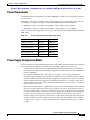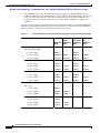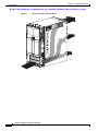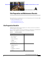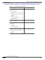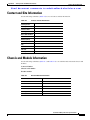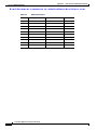
1
Se n d d oc u m e n t c om m e n t s t o m d s f e e d ba ck- do c @ c i s c o . c o m
Cisco Nexus 7000 Series Site Preparation
Guide
June 23, 2008
Americas Headquarters
Cisco Systems, Inc.
170 West Tasman Drive
San Jose, CA 95134-1706
USA
http://www.cisco.com
Tel: 408 526-4000
800 553-NETS (6387)
Fax: 408 527-0883
Text Part Number: OL-15846-01
Se n d d oc u m e n t c om m e n t s t o m d s f e e d ba ck- do c @ c i s c o . c o m
HE SPECIFICATIONS AND INFORMATION REGARDING THE PRODUCTS IN THIS MANUAL ARE SUBJECT TO CHANGE WITHOUT NOTICE. ALL
STATEMENTS, INFORMATION, AND RECOMMENDATIONS IN THIS MANUAL ARE BELIEVED TO BE ACCURATE BUT ARE PRESENTED WITHOUT
WARRANTY OF ANY KIND, EXPRESS OR IMPLIED. USERS MUST TAKE FULL RESPONSIBILITY FOR THEIR APPLICATION OF ANY PRODUCTS.
THE SOFTWARE LICENSE AND LIMITED WARRANTY FOR THE ACCOMPANYING PRODUCT ARE SET FORTH IN THE INFORMATION PACKET THAT
SHIPPED WITH THE PRODUCT AND ARE INCORPORATED HEREIN BY THIS REFERENCE. IF YOU ARE UNABLE TO LOCATE THE SOFTWARE LICENSE
OR LIMITED WARRANTY, CONTACT YOUR CISCO REPRESENTATIVE FOR A COPY.
The following information is for FCC compliance of Class A devices: This equipment has been tested and found to comply with the limits for a Class A digital device, pursuant
to part 15 of the FCC rules. These limits are designed to provide reasonable protection against harmful interference when the equipment is operated in a commercial
environment. This equipment generates, uses, and can radiate radio-frequency energy and, if not installed and used in accordance with the instruction manual, may cause
harmful interference to radio communications. Operation of this equipment in a residential area is likely to cause harmful interference, in which case users will be required
to correct the interference at their own expense.
The following information is for FCC compliance of Class B devices: The equipment described in this manual generates and may radiate radio-frequency energy. If it is not
installed in accordance with Cisco’s installation instructions, it may cause interference with radio and television reception. This equipment has been tested and found to
comply with the limits for a Class B digital device in accordance with the specifications in part 15 of the FCC rules. These specifications are designed to provide reasonable
protection against such interference in a residential installation. However, there is no guarantee that interference will not occur in a particular installation.
Modifying the equipment without Cisco’s written authorization may result in the equipment no longer complying with FCC requirements for Class A or Class B digital
devices. In that event, your right to use the equipment may be limited by FCC regulations, and you may be required to correct any interference to radio or television
communications at your own expense.
You can determine whether your equipment is causing interference by turning it off. If the interference stops, it was probably caused by the Cisco equipment or one of its
peripheral devices. If the equipment causes interference to radio or television reception, try to correct the interference by using one or more of the following measures:
• Turn the television or radio antenna until the interference stops.
• Move the equipment to one side or the other of the television or radio.
• Move the equipment farther away from the television or radio.
• Plug the equipment into an outlet that is on a different circuit from the television or radio. (That is, make certain the equipment and the television or radio are on circuits
controlled by different circuit breakers or fuses.)
Modifications to this product not authorized by Cisco Systems, Inc. could void the FCC approval and negate your authority to operate the product.
The Cisco implementation of TCP header compression is an adaptation of a program developed by the University of California, Berkeley (UCB) as part of UCB’s public
domain version of the UNIX operating system. All rights reserved. Copyright © 1981, Regents of the University of California.
NOTWITHSTANDING ANY OTHER WARRANTY HEREIN, ALL DOCUMENT FILES AND SOFTWARE OF THESE SUPPLIERS ARE PROVIDED “AS IS” WITH
ALL FAULTS. CISCO AND THE ABOVE-NAMED SUPPLIERS DISCLAIM ALL WARRANTIES, EXPRESSED OR IMPLIED, INCLUDING, WITHOUT
LIMITATION, THOSE OF MERCHANTABILITY, FITNESS FOR A PARTICULAR PURPOSE AND NONINFRINGEMENT OR ARISING FROM A COURSE OF
DEALING, USAGE, OR TRADE PRACTICE.
IN NO EVENT SHALL CISCO OR ITS SUPPLIERS BE LIABLE FOR ANY INDIRECT, SPECIAL, CONSEQUENTIAL, OR INCIDENTAL DAMAGES, INCLUDING,
WITHOUT LIMITATION, LOST PROFITS OR LOSS OR DAMAGE TO DATA ARISING OUT OF THE USE OR INABILITY TO USE THIS MANUAL, EVEN IF CISCO
OR ITS SUPPLIERS HAVE BEEN ADVISED OF THE POSSIBILITY OF SUCH DAMAGES.
CCDE, CCENT, Cisco Eos, Cisco Lumin, Cisco Nexus, Cisco StadiumVision, the Cisco logo, DCE, and Welcome to the Human Network are trademarks; Changing the Way
We Work, Live, Play, and Learn is a service mark; and Access Registrar, Aironet, AsyncOS, Bringing the Meeting To You, Catalyst, CCDA, CCDP, CCIE, CCIP, CCNA,
CCNP, CCSP, CCVP, Cisco, the Cisco Certified Internetwork Expert logo, Cisco IOS, Cisco Press, Cisco Systems, Cisco Systems Capital, the Cisco Systems logo,
Cisco Unity, Collaboration Without Limitation, EtherFast, EtherSwitch, Event Center, Fast Step, Follow Me Browsing, FormShare, GigaDrive, HomeLink, Internet Quotient,
IOS, iPhone, iQ Expertise, the iQ logo, iQ Net Readiness Scorecard, iQuick Study, IronPort, the IronPort logo, LightStream, Linksys, MediaTone, MeetingPlace, MGX,
Networkers, Networking Academy, Network Registrar, PCNow, PIX, PowerPanels, ProConnect, ScriptShare, SenderBase, SMARTnet, Spectrum Expert, StackWise, The
Fastest Way to Increase Your Internet Quotient, TransPath, WebEx, and the WebEx logo are registered trademarks of Cisco Systems, Inc. and/or its affiliates in the United
States and certain other countries.
All other trademarks mentioned in this document or Website are the property of their respective owners. The use of the word partner does not imply a partnership relationship
between Cisco and any other company. (0805R)
Any Internet Protocol (IP) addresses used in this document are not intended to be actual addresses. Any examples, command display output, and figures included in the
document are shown for illustrative purposes only. Any use of actual IP addresses in illustrative content is unintentional and coincidental.
Cisco Nexus 7000 System Site Preparation Guide
© 2008 Cisco Systems, Inc. All rights reserved.
Se n d d oc u m e n t c om m e n t s t o m d s f e e d ba ck- do c @ c i s c o . c o m
C O N T E N T S
Preface
v
Audience
v
Document Organization
v
Document Conventions
v
Related Documentation
vi
Obtaining Documentation and Submitting a Service Request
CHAPTER
1
Overview
CHAPTER
2
Preparing the Site
1-1
2-1
About the Nexus 7000 Series
Temperature
Humidity
Altitude
Corrosion
2-1
2-2
2-2
2-2
Dust and Particles
2-3
2-3
Electromagnetic and Radio Frequency Interference
Shock and Vibration
Grounding
3
2-3
2-4
2-4
Power Source
CHAPTER
vi
2-4
Technical Specifications
3-1
Environmental Specifications for the Nexus 7010 System
Physical Specifications for the Nexus 7010 System
Power Specifications for the Nexus 7010 System
Power Requirements 3-3
Power Supply Configuration Modes 3-3
System Clearances
3-2
3-2
3-5
Facility Cooling Requirements
Chassis Airflow
3-1
3-5
3-5
Cisco Nexus 7000 System Site Preparation Guide
OL-15846-01
iii
Contents
Se n d d oc u m e n t c om m e n t s t o m d s f e e d ba ck- do c @ c i s c o . c o m
APPENDIX
A
Site Preparation and Maintenance Records
Site Preparation Checklist
A-1
Contact and Site Information
A-3
Chassis and Module Information
APPENDIX
B
A-1
Cabinet and Rack Requirements
A-3
B-1
General Requirements for Cabinets and Racks
B-1
INDEX
Cisco Nexus 7000 System Site Preparation Guide
iv
OL-15846-01
Se n d d oc u m e n t c om m e n t s t o m d s f e e d ba ck- do c @ c i s c o . c o m
Preface
This preface describes the audience, organization, and conventions of the Cisco Nexus 7000 Series Site
Preparation Guide. It also provides information on how to obtain related documentation.
Audience
This guide is intended for anyone who plans the facilities, including space, floor weighting, power,
cooling, cabling, delivery, and storage, for the installation of the Cisco Nexus 7000 Series 10-slot
chassis.
Document Organization
This document is organized into the following chapters:
Chapter
Description
Chapter 1, “Overview”
Provides an overview of the Nexus 7010 system.
Chapter 2, “Preparing the Site”
Describes the basic site requirements for installing
the Nexus 7010 system.
Chapter 3, “Technical Specifications”
Describes the technical specifications for the
Nexus 7010 system.
Chapter A, “Site Preparation and Maintenance
Records”
Provides a site planning list to prepare your site for
the Nexus 7010 system.
Chapter B, “Cabinet and Rack Requirements”
Describes the cabinet and rack requirements for the
Nexus 7010 system.
Document Conventions
Notes use the following conventions:
Note
Means reader take note. Notes contain helpful suggestions or references to material not covered in the
publication.
Cisco Nexus 7000 System Site Preparation Guide
OL-15846-01
v
Preface
Se n d d oc u m e n t c om m e n t s t o m d s f e e d ba ck- do c @ c i s c o . c o m
Caution
Means reader be careful. In this situation, you might do something that could result in equipment
damage or loss of data.
Related Documentation
Cisco Nexus 7000 Series documentation is available at the following URL:
http://www.cisco.com/en/US/products/ps9402/tsd_products_support_series_home.html
The documentation set for the Cisco Nexus 7000 Series includes the following documents:
Release Notes
Cisco NX-OS Release Notes, Release 4.0
Cisco Nexus 7000 Series FPGA/EPLD Upgrade Release Notes, Release 4.0
Hardware Documents
Cisco Nexus 7000 Series Site Preparation Guide
Cisco Nexus 7000 Series Hardware Installation and Reference Guide
Cisco Nexus 7000 Series Regulatory Compliance and Safety Information
Cisco Nexus 7000 Series Connectivity Management Processor Configuration Guide
Software Documents
The Cisco Nexus 7000 Series ships with the Cisco NX-OS software. You can find software
documentation for Cisco NX-OS at the following URL:
http://www.cisco.com/en/US/products/ps9372/tsd_products_support_series_home.html
The Cisco Datacenter Network Manager (DCNM) supports the Cisco Nexus 7000 Series. You can find
documentation for DCNM at the following URL:
http://www.cisco.com/en/US/products/ps9369/tsd_products_support_series_home.html
Obtaining Documentation and Submitting a Service Request
For information on obtaining documentation, submitting a service request, and gathering additional
information, see the monthly What’s New in Cisco Product Documentation, which also lists all new and
revised Cisco technical documentation, at:
http://www.cisco.com/en/US/docs/general/whatsnew/whatsnew.html
Subscribe to the What’s New in Cisco Product Documentation as a Really Simple Syndication (RSS) feed
and set content to be delivered directly to your desktop using a reader application. The RSS feeds are a free
service and Cisco currently supports RSS version 2.0.
Cisco Nexus 7000 System Site Preparation Guide
vi
OL-15846-01
Se n d d oc u m e n t c om m e n t s t o m d s f e e d ba ck- do c @ c i s c o . c o m
C H A P T E R
1
Overview
The Cisco Nexus 7000 Series devices support end-to-end data center connectivity, consolidating IP,
storage, and interprocess communication (IPC) networks onto a single Ethernet fabric. The Cisco Nexus
7000 Series features a 10-slot chassis that provides front-to-back airflow and an integrated cable
management system that facilitates device installation, operation, and cooling in both new and existing
data centers. This chapter provides an overview of the Nexus 7010 system features.
The Nexus 7000 Series has a 10-slot chassis that can support a maximum of two supervisor modules and
up to eight I/O modules.
Table 1-1 describes the features of the Nexus 7010 system.
Table 1-1
Nexus 7010 System Features
Feature
Description 1
Chassis
10-slot chassis for holding supervisor and I/O modules,
system and fabric fan trays, fabric modules, and power
supplies.
Supervisor Modules
1–2—shipped in the chassis.
I/O Modules
0–8—shipped in the chassis.
System Fan Tray
2—shipped in the chassis.
Fabric Fan Tray
2—shipped in the chassis.
Fabric Modules
3–5—shipped in the chassis.
Power Supplies
2–3—shipped with the chassis but boxed separately.
1. The quantity of modules and fan trays shipped with the chassis will vary depending on your order.
For information about preparing your site for the Nexus 7000 Series devices, see Chapter 2, “Preparing
the Site.”
For information about installing the Nexus 7000 Series devices, see the Cisco Nexus 7000 Series
Hardware Installation and Reference Guide. For translations of the warnings in that guide, see the Cisco
Nexus 7000 Series Regulatory Compliance and Safety Information document.
Cisco Nexus 7000 System Site Preparation Guide
OL-15846-01
1-1
Chapter 1
Overview
Se n d d oc u m e n t c om m e n t s t o m d s f e e d ba ck- do c @ c i s c o . c o m
Cisco Nexus 7000 System Site Preparation Guide
1-2
OL-15846-01
Se n d d oc u m e n t c om m e n t s t o m d s f e e d ba ck- do c @ c i s c o . c o m
C H A P T E R
2
Preparing the Site
This chapter describes the basic site requirements that you should be aware of as you prepare to install
your Nexus 7000 Series devices.
This chapter includes the following sections:
•
About the Nexus 7000 Series, page 2-1
•
Temperature, page 2-2
•
Humidity, page 2-2
•
Altitude, page 2-2
•
Dust and Particles, page 2-3
•
Corrosion, page 2-3
•
Electromagnetic and Radio Frequency Interference, page 2-3
•
Shock and Vibration, page 2-4
•
Grounding, page 2-4
•
Power Source, page 2-4
About the Nexus 7000 Series
Environmental factors can adversely affect the performance and longevity of your system. The Nexus
7000 Series devices require a dry, clean, well-ventilated, and air-conditioned environment. To ensure
normal operation, you must maintain ambient airflow. If the airflow is blocked or restricted and or if the
intake air is too warm, an overtemperature condition can occur and the environmental monitor on the
system will shut down to protect the system components.
You can mount up to two chassis in a rack with little or no clearance above and below the chassis. You
must, however, have enough room in front for loading the chassis using a mechanical lift and enough
room in the rear for removing the system components. When mounting the chassis in a rack with other
equipment, ensure that the exhaust from other equipment does not blow into the air intake vent of the
chassis. If your site has warm and cold aisles, align the rack or cabinet air intake to a cold aisle and
exhaust to a warm aisle.
Cisco Nexus 7000 System Site Preparation Guide
OL-15846-01
2-1
Chapter 2
Preparing the Site
Temperature
Se n d d oc u m e n t c om m e n t s t o m d s f e e d ba ck- do c @ c i s c o . c o m
Temperature
When you install the Nexus 7000 Series, make sure that the system has adequate airflow from front to
back and do not block the air inlet or the air exhaust.
Temperature extremes can cause the Nexus 7000 Series devices to operate at reduced efficiency and
cause a variety of problems, including premature aging and failure of chips, and failure of devices.
Extreme temperature fluctuations can cause chips to become loose in their sockets. The Nexus 7000
Series devices should be operating in an environment that is not colder than 41°F (5°C) or hotter than
104°F (40°C).
Make sure that the chassis has adequate ventilation; do not place the chassis next to a heat source of any
kind, including heating vents during winter.
Adequate ventilation is particularly important at high altitudes. Make sure that all slots and openings on
the system remain unobstructed, especially the fan vents on the chassis. Clean the installation site at
regular intervals to avoid buildup of dust and debris, which can cause a system to overheat. If the Nexus
7000 series was exposed to abnormally cold temperatures, allow a 2-hour warm-up period to bring it up
to a normal operating temperature before you turn the system on. Otherwise, you can damage the internal
components.
Note
The Nexus 7000 Series devices is equipped with internal air temperature sensors that trigger a minor
alarm at 104°F (40°C) and a major alarm at 131°F (55°C).
Humidity
High humidity conditions can cause moisture to seep into the Nexus 7000 Series devices. Moisture can
cause corrosion of internal components and degradation of properties such as electrical resistance,
thermal conductivity, physical strength, and size. The Nexus 7000 Series is rated to operate at 8 to 80
percent relative humidity, with a humidity gradation of 10 percent per hour.
The Nexus 7000 Series devices can withstand from 5 to 90 percent relative humidity when you store it.
Buildings in which climate is controlled by air-conditioning in the warmer months and by heat during
the colder months usually maintain an acceptable level of humidity for system equipment. However, if
a Nexus 7000 Series device is located in an unusually humid location, you can use a dehumidifier to
maintain the humidity within an acceptable range.
Altitude
If you operate a Nexus 7000 Series device at a high altitude (low pressure), the efficiency of forced and
convection cooling is reduced and can result in electrical problems that are related to arcing and corona
effects. This condition can also cause sealed components with internal pressure, such as electrolytic
capacitors, to fail or to perform at a reduced efficiency. The Nexus 7000 Series is rated to operate at
altitudes from –500 to 13,123 feet (–152 to 4,000 meters). You can store the system at altitudes of –1,000
to 30,000 feet (–305 to 9,144 meters).
Cisco Nexus 7000 System Site Preparation Guide
2-2
OL-15846-01
Chapter 2
Preparing the Site
Dust and Particles
Se n d d oc u m e n t c om m e n t s t o m d s f e e d ba ck- do c @ c i s c o . c o m
Dust and Particles
Exhaust fans cool power supplies and system fan trays cool systems by drawing in air and exhausting air
out through various openings in the chassis. However, fans also ingest dust and other particles, causing
contaminant buildup in the system and increased internal chassis temperature. A clean operating
environment can greatly reduce the negative effects of dust and other particles, which act as insulators
and interfere with the mechanical components in the system.
Note
You can use an optional air filter if you install a Nexus 7000 series device in a nonclean environment.
In addition to regular cleaning, follow these precautions to avoid contamination of your equipment:
•
Do not permit smoking near the Nexus 7000 Series device.
•
Do not permit food or drink near the Nexus 7000 Series device.
Corrosion
The corrosion of system connectors is a gradual process that can eventually lead to intermittent failures
of electrical circuits. The oil from your fingers or prolonged exposure to high temperature or humidity
can corrode the gold-plated edge connectors and pin connectors on various components in the Nexus
7000 Series devices. To prevent corrosion, avoid touching contacts on modules and protect the system
from extreme temperatures and moist, salty environments.
Electromagnetic and Radio Frequency Interference
Electromagnetic interference (EMI) and radio frequency interference (RFI) from the Nexus 7000 Series
can adversely affect devices such as radio and television (TV) receivers operating near the system. Radio
frequencies that emanate from the Nexus 7000 Series device can also interfere with cordless and
low-power telephones. Conversely, RFI from high-power telephones can cause spurious characters to
appear on the system monitor.
RFI is defined as any EMI with a frequency above 10 kHz. This type of interference can travel from the
system to other devices through the power cable and power source or through the air like transmitted
radio waves. The Federal Communications Commission (FCC) publishes specific regulations to limit the
amount of EMI and RFI emitted by computing equipment. Each Nexus 7000 Series device meets these
FCC regulations.
To reduce the possibility of EMI and RFI, follow these guidelines:
•
Cover all open expansion slots with a metal filler.
•
Always use shielded cables with metal connector shells for attaching peripherals to the system.
When wires are run for any significant distance in an electromagnetic field, interference can occur
between the field and the signals on the wires and cause the following implications:
•
Bad wiring can result in radio interference emanating from the plant wiring.
•
Strong EMI, especially when it is caused by lightning or radio transmitters, can destroy the signal
drivers and receivers in the chassis and even create an electrical hazard by conducting power surges
through lines into equipment.
Cisco Nexus 7000 System Site Preparation Guide
OL-15846-01
2-3
Chapter 2
Preparing the Site
Shock and Vibration
Se n d d oc u m e n t c om m e n t s t o m d s f e e d ba ck- do c @ c i s c o . c o m
Note
To predict and prevent strong EMI, you might need to consult experts in radio frequency interference
(RFI).
The wiring is unlikely to emit radio interference if you use twisted-pair cable with a good distribution
of grounding conductors. If you exceed the recommended distances, use a high-quality twisted-pair
cable with one ground conductor for each data signal when applicable.
If the wires exceed the recommended distances, or if wires pass between buildings, give special
consideration to the effect of a lightning strike in your vicinity. The electromagnetic pulse caused by
lightning or other high-energy phenomena can easily couple enough energy into unshielded conductors
to destroy electronic devices. You may want to consult experts in electrical surge suppression and
shielding if you had similar problems in the past.
Shock and Vibration
The Nexus 7000 Series has been shock- and vibration-tested for operating ranges, handling, and
earthquake standards to Network Equipment Building Standards (NEBS) Zone 4 per GR-63-Core.
Grounding
The Nexus 7000 Series is sensitive to variations in voltage supplied by the AC-power source.
Overvoltage, undervoltage, and transients (or spikes) can erase data from the memory or cause
components to fail. To protect against these types of problems, you should always properly ground power
cables.
Power Source
You should use a dedicated power circuit (rather than sharing a circuit with other heavy electrical
equipment). We recommend that the Nexus 7000 Series have two separate AC-power sources. For each
power supply, connect each of its AC-power cables to an independent power source.
Before you connect the power supplies to the AC power, you must install the power supplies in the Nexus
7010 chassis and you must have one 20A AC receptacle for each power cable that you need to connect
to the Nexus 7010 power supplies. Each receptacle should be on a separate circuit and should be located
on the rack within reach of the power cables when they are attached to the power supplies.
Cisco Nexus 7000 System Site Preparation Guide
2-4
OL-15846-01
Se n d d oc u m e n t c om m e n t s t o m d s f e e d ba ck- do c @ c i s c o . c o m
C H A P T E R
3
Technical Specifications
This chapter describes the technical specifications for the Nexus 7010 system and includes these
sections:
•
Environmental Specifications for the Nexus 7010 System, page 3-1
•
Physical Specifications for the Nexus 7010 System, page 3-2
•
Power Specifications for the Nexus 7010 System, page 3-2
•
Facility Cooling Requirements, page 3-5
•
Chassis Airflow, page 3-5
Environmental Specifications for the Nexus 7010 System
Table 3-1 lists the environmental specifications for the Nexus 7010 system.
Table 3-1
Environmental Specifications for the Nexus 7010 System
Description
Temperature
Specification
Ambient operating
41 to 104ºF (5 to 40ºC)
Ambient nonoperating
–40 to 158ºF (–40 to 70ºC)
Relative humidity Ambient (noncondensing) operating
(RH)
Altitude
Noise
5 to 90% (45 to 50% recommended)
Ambient (noncondensing)
nonoperating and storage
5 to 95%
Operating
–500 to 13,123 feet (152 to 4,000 meters)
Storage
–1,000 to 30,000 feet (–305 to 9,144
meters)
Sound pressure levels
Without air filter
67.2 dBA
With air filter
70.2 dBA
Sound power levels
Without air filter
78.9 dBA
With air filter
81.7 dBA
Cisco Nexus 7000 System Site Preparation Guide
OL-15846-01
3-1
Chapter 3
Technical Specifications
Physical Specifications for the Nexus 7010 System
Se n d d oc u m e n t c om m e n t s t o m d s f e e d ba ck- do c @ c i s c o . c o m
Physical Specifications for the Nexus 7010 System
Table 3-2 lists the physical specifications for the Nexus 7010 system.
Table 3-2
Dimensions for the Nexus 7010 Chassis
Description
Width
Chassis
17.3 inches (43.9 cm) 38.0 inches (96.5 cm)
Height1
Depth
36.5 inches (92.7 cm) (21.0 RU)
1. The height includes the bottom support rail.
Table 3-3 lists the weights and quantities of the components that make up each Nexus 7010 system.
These weights do not include the rack or cabinet that holds the Nexus 7010 system or the interface and
power cables. For those weights, see the documentation provided by the manufacturers of those
components.
Table 3-3
Weights, Quantities, and Mean Time Between Failure for the Nexus 7010 Chassis
Components
Component
Weight per Unit
Quantity
MTBF1 (hours) per Unit
Chassis
200 lbs. (90.9 kg)
1
264,649
Supervisor module
10 lbs. (4.5 kg)
2
79,725
48-port I/O module
14 lbs. (6.4 kg)
74,373
32-port I/O module with SFP+ 18.5 lbs. (8.4 kg)
transceivers
1 to 8 (mix of either
or both types of I/O
modules)
Fabric module
4 lbs. (1.8 kg)
3 to 5
649,295
System fan tray
20 lbs. (9.1 kg)
2
264,649
Fabric fan tray
5 lbs. (2.3 kg)
2
264,649
Power supply
18 lbs. (8.2 kg)
2 to 3
204,415
Mid-frame doors and frame
(optional)
N/A
0 or 1
N/A
33,652
1. The predicted mean time between failure (MTBF) is based on Bellcore Methodology.
Power Specifications for the Nexus 7010 System
The number of power supplies that your Nexus 7010 system requires depends on the numbers and types
of modules that you include in the system chassis and the power redundancy mode that you are using.
The following topics explain how to calculate the system power requirements and the amount of power
available for each type of power redundancy mode:
•
Power Requirements, page 3-3
•
Power Supply Configuration Modes, page 3-3
Cisco Nexus 7000 System Site Preparation Guide
3-2
OL-15846-01
Chapter 3
Technical Specifications
Power Specifications for the Nexus 7010 System
Se n d d oc u m e n t c om m e n t s t o m d s f e e d ba ck- do c @ c i s c o . c o m
Power Requirements
To determine the power requirements of the Nexus 7000 System, add the power requirements of each of
its components.
The quantity of each type of module in your system depends on how you configure your system. You
can configure your system according to the following minimum and maximum guidelines:
•
(Minimum) 1 supervisor module, 1 I/O module, 3 fabric modules, 2 power supplies
•
(Maximum) 2 supervisor modules, 8 I/O modules, 5 fabric modules, 3 power supplies
Table 3-4 lists the power requirements for each type of module that can be included with the the Nexus
7010 system.
Table 3-4
Power requirements for the Nexus 7010 system
Component
Maximum
Typical
Supervisor module
200 watts
190 watts
48-port I/O module
400 watts
358 watts
32-port I/O module
750 watts
611 watts
Fabric module
60 watts
55 watts
All fan trays (total)
2184 watts
300 watts
Power supply
300 watts
200 watts
Power Supply Configuration Modes
You can configure one of the following power modes to either utilize all of the available power provided
by the installed power supplies or to provide power redundancy when there is a power loss:
•
Combined mode—This mode provides the maximum amount of available power by utilizing the
combined power output from all installed power supplies for system operations. This mode does not
provide a redundancy.
•
Power-supply redundancy mode—This mode lets you replace a power supply during system
operations. All power supplies are active but the available power is calculated as the least amount
of power available from all but one of the power supplies (N+1) and the reserve power is the amount
of power output by the power supply that can output the most power. For example, if three power
supplies output 3.0 kW, 6.0 kW, and 6.0 kW, the available power is 9.0 kW (3.0 kW + 6.0 kW) and
the reserve power is 6.0 kW.
•
Input source redundancy mode—This mode takes power from two electrical grids so that if one grid
goes down, the other grid can provide the power needed by the system. Each grid powers half of
each power supply (grid A is connected to the Input 1 receptacle on each power supply and grid B
is connected to the Input 2 receptacle on each power supply). The available power is calculated as
the amount of power output by the portions of power supplies connected to the same grid. For
example, if three power supplies are connected to a 110V grid and a 220V grid, each power supply
outputs 1.2 kW for the 110V grid and 3.0 kW for the 220V grid. The available power would be
3.6 kW (1.2 kW + 1.2 kW + 1.2 kW) and the reserve power would be 9.0 kW (3.0 kW + 3.0 kW +
3.0 kW).
Cisco Nexus 7000 System Site Preparation Guide
OL-15846-01
3-3
Chapter 3
Technical Specifications
Power Specifications for the Nexus 7010 System
Se n d d oc u m e n t c om m e n t s t o m d s f e e d ba ck- do c @ c i s c o . c o m
•
Full redundancy mode—This mode provides both power-supply redundancy and input-source
redundancy. This mode lets you replace a power supply without interrupting system operations, and
it lets you continue powering the system if one of two grids goes down. The available power is
calculated as the lesser amount of output power for power supply redundancy or input source
redundancy.
Table 3-5 shows the amount of power that each power mode makes available for your Nexus 7000 system
depending on the hardware installed in your system, the amount of power input to the power supplies,
the voltage used for the input power, and the power mode you are using.
Table 3-5
Power Availability for Each Power Mode Configuration and Power Supply Installation
Combined
mode
Power
supply
redundancy
mode
Input source Full
redundancy redundancy
mode
mode
1 power supply
6,000 W
-
3,000 W
-
2 power supplies
12,000 W
6,000 W
6,000 W
6,000 W
3 power supplies
18,000 W
12,000 W
9,000 W
9,000 W
1 power supply
4,200 W
-
1,200 W
-
2 power supplies
8,400 W
4,200 W
2,400 W
2,400 W
3 power supplies
12,600 W
8,400 W
3,600 W
3,600 W
1 power supply
2,400 W
-
1,200 W
-
2 power supplies
4,800 W
2,400 W
2,400 W
2,400 W
3 power supplies
7,200 W
4,800 W
3,600 W
3,600 W
1 power supply
3,000 W
-
-
-
2 power supplies
6,000 W
3,000 W
-
-
3 power supplies
9,000 W
6,000 W
-
-
1 power supply
1,200 W
-
-
-
2 power supplies
2,400 W
1,200 W
-
-
3 power supplies
3,600 W
2,400 W
-
-
Dual inputs per power supply unit
220 V and 220 V inputs
220 V and 110 V inputs
110 V and 110 V inputs
Single inputs per power supply unit
220 V input
110 V input
Cisco Nexus 7000 System Site Preparation Guide
3-4
OL-15846-01
Chapter 3
Technical Specifications
System Clearances
Se n d d oc u m e n t c om m e n t s t o m d s f e e d ba ck- do c @ c i s c o . c o m
System Clearances
You must provide adequate clearance for installing the system and replacing system modules. The aisle
in front of the system must have at least 38.0 inches of clearance to handle the depth of the system
(additional clearance might be necessary for the mechanical lift used to position the chassis in front of
the rack). The aisle in back of the system must provide at least 30 inches of clearance for replacing the
system fan trays.
Facility Cooling Requirements
The Nexus 7000 Series 10-slot chassis dissipates considerable power that generates much heat. The
following is the heat dissipation requirement for the 10-slot chassis:
•
26,562 BTUs per hour
Chassis Airflow
The Nexus 7000 Series 10-slot chassis has a set of fan trays that are used to cool the rest of the chassis
modules. Cool air flows in at the bottom front of the chassis and flows through the chassis and through
the fans in the fan trays before being exhausted at the top rear of the chassis (see Figure 3-1).
Cisco Nexus 7000 System Site Preparation Guide
OL-15846-01
3-5
Chapter 3
Technical Specifications
Chassis Airflow
Se n d d oc u m e n t c om m e n t s t o m d s f e e d ba ck- do c @ c i s c o . c o m
Airflow Through the 10-Slot Chassis
270544
Figure 3-1
Cisco Nexus 7000 System Site Preparation Guide
3-6
OL-15846-01
Se n d d oc u m e n t c om m e n t s t o m d s f e e d ba ck- do c @ c i s c o . c o m
A P P E N D I X
A
Site Preparation and Maintenance Records
This appendix provides a site planning list that you can use when preparing your site for the Nexus 7000
series devices and includes these sections:
•
Site Preparation Checklist, page A-1
•
Contact and Site Information, page A-3
•
Chassis and Module Information, page A-3
Site Preparation Checklist
Planning the location and layout of your equipment rack or cabinet is essential for successful device
operation, ventilation, and accessibility.
Table A-1 lists the site planning tasks that we recommend that you complete before you install the Nexus
7000 series. Your completion of each task ensures a successful device installation.
Table A-1
Site Planning Checklist
Planning Activity
Verification Time and Date
Space evaluation:
•
Space and layout
•
Floor covering
•
Impact and vibration
•
Lighting
•
Physical access
•
Maintenance access
Environmental evaluation:
•
Ambient temperature
•
Humidity
•
Altitude
•
Atmospheric contamination
•
Airflow
Cisco Nexus 7000 System Site Preparation Guide
OL-15846-01
A-1
Appendix A
Site Preparation and Maintenance Records
Site Preparation Checklist
Se n d d oc u m e n t c om m e n t s t o m d s f e e d ba ck- do c @ c i s c o . c o m
Table A-1
Site Planning Checklist (continued)
Planning Activity
Verification Time and Date
Power evaluation:
•
Input power type
•
Power receptacles
•
Receptacle proximity to the equipment
•
Dedicated (separate) circuits for power
redundancy
•
UPS for power failures
•
Grounding: proper gauge wire and lugs
•
Circuit breaker size
Grounding evaluation:
•
Data center ground
Cable and interface equipment evaluation:
•
Cable type
•
Connector type
•
Cable distance limitations
•
Interface equipment (transceivers)
EMI evaluation:
•
Distance limitations for signaling
•
Site wiring
•
RFI levels
Cisco Nexus 7000 System Site Preparation Guide
A-2
OL-15846-01
Appendix A
Site Preparation and Maintenance Records
Contact and Site Information
Se n d d oc u m e n t c om m e n t s t o m d s f e e d ba ck- do c @ c i s c o . c o m
Contact and Site Information
Use the following worksheet (Table A-2) to record contact and site information.
Table A-2
Contact and Site Information
Contact person
Contact phone
Contact e-mail
Building/site name
Data center location
Floor location
Address (line 1)
Address (line 2)
City
State
ZIP code
Country
Chassis and Module Information
Use the following worksheets (Table A-3 and Table A-4) to record information about the chassis and
modules.
Contract Number
Chassis serial number
Product number
Table A-3
Network-Related Information
Device IP address
Device IP netmask
Hostname
Domain name
IP broadcast address
Gateway/router address
DNS address
Cisco Nexus 7000 System Site Preparation Guide
OL-15846-01
A-3
Appendix A
Site Preparation and Maintenance Records
Chassis and Module Information
Se n d d oc u m e n t c om m e n t s t o m d s f e e d ba ck- do c @ c i s c o . c o m
Table A-4
Slot
Module Information
Module Type
Module Serial Number
Notes
1
2
3
4
5
Supervisor
6
Supervisor
7
8
9
10
Cisco Nexus 7000 System Site Preparation Guide
A-4
OL-15846-01
Se n d d oc u m e n t c om m e n t s t o m d s f e e d ba ck- do c @ c i s c o . c o m
A P P E N D I X
B
Cabinet and Rack Requirements
This appendix describes the cabinet and rack requirements and includes these sections:
•
General Requirements for Cabinets and Racks, page B-1
General Requirements for Cabinets and Racks
This section provides the Nexus 7000 Series requirements for the following types of racks and cabinets,
assuming an external ambient air temperature range of 41 to 104°F (5 to 40°C):
Note
•
Standard perforated cabinets
•
Solid-walled cabinets with a roof fan tray (bottom to top cooling)
•
Standard open racks
•
Four-post telco racks
If you select an enclosed cabinet, we recommend that you use one of the following thermally validated
types: standard perforated or solid-walled with a fan tray.
To correctly install the Nexus 7000 Series in a hot-aisle cold-aisle environment, you should fit a cabinet
with baffles to prevent exhaust air from recirculating.
Note
The verified cabinet vendors for the Nexus 7000 Series are Panduit and Chatsworth.
The rack or cabinet used to hold a Nexus 7000 Series should meet the following requirements:
•
Use a standard 19-inch, four-post Electronic Industries Alliance (EIA) cabinet or rack, with
mounting rails that conform to English universal hole spacing per section 1 of the
ANSI/EIA-310-D-1992 standard.
•
Have at least 21 rack units (RU) of usable vertical rack space for one Nexus 7000 series device and
42 RU for two Nexus 7000 Series devices (45 RU is recommended).
Each of the following optional requirements are site specific:
•
Accommodate up to two Nexus 7000 10-slot chassis and provide cable management for up to 384
ports for each Nexus 7000 series device.
•
Provide the features required for the AC power distribution units (PDUs) for the power supplies
installed in each chassis.
Cisco Nexus 7000 System Site Preparation Guide
OL-15846-01
B-1
Appendix B
Cabinet and Rack Requirements
General Requirements for Cabinets and Racks
Se n d d oc u m e n t c om m e n t s t o m d s f e e d ba ck- do c @ c i s c o . c o m
•
Have the capacity to accommodate cable routing within the cabinet without blocking access to any
of the pluggable modules installed in a chassis, and without blocking any airflow on the inlet and
exhaust vents of the chassis. The cables should be able to be routed out the top or bottom of the
cabinet.
•
Where necessary, have a Seismic rating of Network Equipment Building Standards (NEBS) Zone 3
or Zone 4, per GR-63-CORE if required.
•
Have a minimum gross load rating of 2000 lbs. (907.2 kg) (static load rating) if supporting two
devices.
Cisco Nexus 7000 System Site Preparation Guide
B-2
OL-15846-01
Se n d d oc u m e n t c om m e n t s t o m d s f e e d ba ck- do c @ c i s c o . c o m
I N D EX
A
I
altitude
input-source redundancy
2-2
described
3-3
C
chassis airflow
combined mode
physical specifications
3-3
cooling requirements
corrosion
P
3-5
power modes
3-5
combined
2-3
3-2
3-3
3-3
full redundancy
3-4
input-source redundancy
D
power-supply redundancy
power source
documentation
additional publications
dust and particles
3-3
2-4
power specifications
1-vi
3-3
3-2
power-supply redundancy
2-3
described
3-3
E
R
electromagnetic interference (EMI)
environmental specifications
3-1
2-3
radio frequency interference (RFI)
related documents
2-3
1-vi
requirements
G
grounding
cabinets and racks
B-1
2-4
S
H
humidity
shock and vibration
2-2
2-4
site preparation checklist
A-1
T
temperature
2-2
Cisco Nexus 7000 System Site Preparation Guide
OL-15846-01
IN-1
Index
Se n d d oc u m e n t c om m e n t s t o m d s f e e d ba ck- do c @ c i s c o . c o m
Cisco Nexus 7000 System Site Preparation Guide
IN-2
OL-15846-01