1
CHAMBERLAIN
=
®
GARAGE
_Models
For Residential
Owner's
The Chamberlain Group, Inc •
845 Larch Avenue
Elmhurst, Illinois 60126-1196
www.,chamberiain com
DOOR OPENER
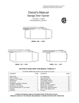
WD962KD
WD962KLD
Use Only
Manual
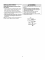
a Please read this manual and the enclosed safety
materials carefully!
e Fasten the manual near the garage door after installation.
e The door WILL NOT CLOSE unless The Protector System ® is connected
and properly aligned.
•
Periodic checks of the opener are required to ensure safe operation.
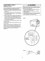
u The model number label is located on the left side panel of your opener.
OF COHTSNTS
2-7
Adjustment
Preparing your garage door ........................................
Tools needed
3
3
Planning
........................................................
4-5
Carton inventory ........................................................
6
Hardware
7
..................................................
inventory
Assembly
8.1 t
the travel limits
Setting the force
..........................................
28
29
Test the safety reversal system ..........................
Test The Protector System @ (safety sensors) .............
Operation
Operation
30
30
3 t-37
safety instructions
Using your opener
31
..................................................
8
Fasten the rail to the motor unit ......................................
9
Care of your opener ......................................................
33
install the idler pulley ...................................................
9
To open the door manually
33
Install the belt and attach the belt cap retainer
Set the tension ....................................................
.............. 10
11
Installation
11-26
Using the wall-mounted
control console
31
the rail and install the trolley .......................
......................
.....................................
Battery backup ........................................................
34
Having a problem?
35
Diagnostic
chart
(Troubleshooting)
.....................
36
Programming
37.38
11
12
To add or reprogram
Install the header bracket .......................................
t3
To erase all codes from motor unit memory
Attach the rail to the header bracket ........................
14
3-Button
Position the opener ....................................................
15
Hang the opener .......................................................
install the control console ...........................................
16
17
To add, reprogram or change a
Keyless Entry PIN ......................................................
Install the battery
18
.....................................................
Installation safety instructions ..................................
Determine the header bracket location ...................
Install the lights ..........................................................
18
Attach the emergency release rope and handle .......... 19
Electrical requirements ............................................
20
32
............................................................
Assemble
Program
................................
2
...........................................................
Safety symbol and signal word review ...........................
28.30
............................................
Introduction
.........
TABLE
remotes
Repair
Installation
a hand-held
remote
control .......... 37
.................
Parts
Connect the door arm to the trolley ......................... 26-27
Repair
38
39.40
parts
.........................................
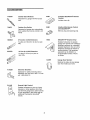
Accessories
Notes
37
paris ............................................................
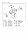
Motor unit assembly
Install The Protector System e (safety sensors) ........ 21-23
Fasten the door bracket .....................................
24-25
37
.......................................................
39
40
41
42-43
Parts
and
Service
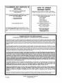
Warranty
44
44
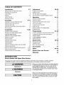
|NTRODUCTION
Safety
Symbol
and
Signal
Word
Review
This garage door opener has been designed and tested to offer safe service provided it is installed, operated,
maintained and tested in strict accordance with the instructions and warnings contained in this manual.
Mechanical
When you see these Safety Symbols and Signal Words on
the following pages, they will alert you to the possibility of
serious injury or death if you do not comply with the
warnings that accompany them The hazard may come
from something mechanical or from electric shock Read
the warnings carefully
Electrical
When you see this Signal Word on the following pages, it
will alert you to the possibility of damage to your garage
door and/or the garage door opener if you do not comply
with the cautionary statements that accompany it. Read
them carefully
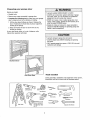
Preparing
your
garage
door
Before you begin:
o Disable locks
o Remove any ropes connected to garage door.
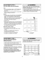
- Complete the following test to make sure your garage
door is balanced and is not sticking or binding:
1 Lift the door about halfway as shown Release the
door. if balanced, it should stay in place, supported
entirely by its springs
2 Raise and lower the door to see if there is any
binding or sticking
To prevent possible SERIOUSINJURYor DEATH:
- ALWAYSca!l a trained door systemstechnicianif garage
door binds, sticks, or is out of balance An unbalanced
garagedoor may not reversewhen required
o NEVERtry to loosen, moveor adjust garage door, door
springs, cables,pulleys,bracketsor their hardware,a!; of
which are under EXTREMEtension
° DisableALL locks and removeALL ropes connectedto
garagedoor BEFOREinstalling and operatinggaragedoor
openerto avoid entanglement.
If your door binds, sticks, or is out of balance, call a
trained door systems technician
To preventdamageto garagedoor and opener:
• ALWAYSdisablelocks BEFOREinstalling and operating
the opener
• ONLYoperategaragedoor opener at !20V, 60 Hz to avoid
malfunctionand damage
Sectional Door
Tools
One-Piece Door
needed
During assembly, installation and adjustment of the opener,
instructions will call for hand tools as illustrated below
Level (optional)
_
Penc_f
Hack Saw
Tape Measure
Wire Cutters
Drill
3/16', 5ft 6"
_,_
and 5/32"
Step Ladder
Screwdriver
Adjustable End Wrench
and 1/4"
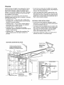
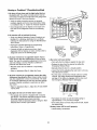
Planning
• Do you have an access door in addition to the garage
door? If not, Model 7702CB Emergency Key Release is
required See Accessories page
identify the type and height of your garage door Survey
your garage area to see if any of the conditions below
apply to your installation Additional materials may be
required You may find it helpful to refer back to this page
and the accompanying illustrations as you proceed with
the installation of your opener,r
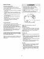
• Look at the garage door where it meets the floor Any
gap between the floor and the bottom of the door must
not exceed 1/4" (6 ram) Otherwise, the safety reversal
system may not work properly See Adjustment Step 3_
Floor or door should be repaired
Depending on your requirements, there are several
installation steps which may call for materials or hardware
not included in the carton_
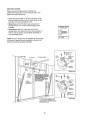
o installation Step 1 - Look at the wall or ceiling above
the garage door° The header bracket must be securely
fastened to structural supports
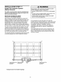
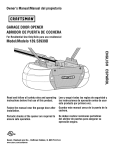
SECTIONAL DOOR INSTALLATIONS
o Do you have a steel, aluminum, fiberglass or glass
panel door? If so, horizontal and vertical reinforcement
is required (installation Step 12),
* Installation Step 5 - Do you have a finished ceiling in
your garage? If so, a support bracket and additional
fastening hardware may be required
o The opener should be installed above the center of the
door, If there is a torsion spring or center bearing plate
in the way of the header bracket, it may be installed
within 4 feet (1_2 m) to the left or right of the door
center See Installation Steps 1 and 12
- Installation Step 11 - Depending upon garage
construction, extension brackets or wood blocks may be
needed to instal! sensors
o installation Step 11 - Alternate floor mounting of the
safety reversing sensor will require hardware not
provided,
SECTIONAL
• If your door is more than 7 feet (21 m) high, see rail
extension kits listed on Accessories page
DOOR INSTALLATION
FINISHED CEILING
Support bracket &
fastening hardware
is required.
See page 16
Horizontal and vertical reinlorcement
is needed for ftghtwetght garage doors
(libergfass, steel, atuminum_ door with
glass panels, etc ) See page 24 for details,
Header Wall
OR
TorsionSpring
Wallo
mounted
Access
ODor
Door
Conlrol
1
Vertica!
Centerline
o! Garage Door
CLOSED POSITION
H_ader
5
Bracket Trolley
Bolt
Trolley
O
Garage
Door
Spring
Belt
Emergency Release
Rope & Handle
Sensor
Gap between floor
and bottom o! door
must not exceed 1/4" (6 mm)
Safely
Reversing
Sensor
Curved
Door
Arm
eader
rail
arage
_or
Bracket
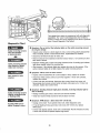
Planning
(Continued)
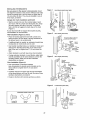
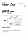
ONE-PIECE DOOR INSTALLATIONS
Without a properlyworkingsafety reversalsystem, persons
(particularlysmaIEchildren) could be SERIOUSLYINJUREDor
KILLEDby a closing garagedoor.
- The gap betweenthe bottom of the garagedoor and the floor
MUSTNOTexceed1/4" (6 ram) Otherwise,the safety
reversalsystemmay not work properly.
oThe floor or the garagedoor MUSTbe repairedto eliminate
the gap.
- Generally, a one-piece door does not require
reinforcement.. If your door is lightweight, refer to the
information relating to sectional doors in installation
Step 12..
• Depending on your door's construction, you may need
additional mounting hardware for the door bracket
(Step !2)
ONE-PIECE
DOOR WITHOUT
TRACK
FINISHED CEILING
SupporZ brackel
& fastening
hardware is required
See page 16
_'_ -_
Header WatI
Rall
Motar
,_.,___.__,_
Access
Unit
WalFmeunted
Door Control
_]
IIII
"Safety Reversing
Safety Reversing Seoso_
ONE-PIECE
ap between floe
Sensor
and bottom o! doer must not exceed 1I4" (6 ram)
DOOR WITH TRACK
CLOSED POSITION
TrolIey Stop Bolt
Belt
Trolley
Rail
O
Door
Garage
Door
"Safety
Reversing
Sensor
Gap between floor
Sensor
and bottom of door
must not exceed !I4" (6 ram).
Reversing
'**j
5
Straight
Door
Arm
Emergency
Release
Rope &
Handle
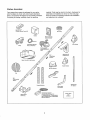
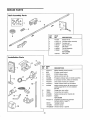
Carton
Inventory
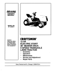
Your garage door opener is packaged in one carton
which contains the motor unit and all parts illustrated
below.. Accessories will depend on the model purchased..
If anything is missing, carefully check the packing
material Parts may be stuck in the foam. Hardware for
assembly and installation is shown on the next page..
Save the carton and packing material until installation
and adjustment is complete..
SECURITY÷ _
3-Sutton Remote Control (2)
Battery
Motion Detecting
Control Console
Door Bracket
2*Conductor Be!_ Wire
White & While/Red
Trolley
Parking Assfst
(Model WD962KLD
only)
SECURITY÷ _
Keyleas Entry
Rail
Center/Back
Sections
Motor Unit with 2 Ught Lenses
Heeder Bracket
Belt Cap Retainer
Belt
Rail
Front (header)
Section
Hanging Brackets
CurvedDoor
Arm Section
Safety Sensor
Bracket (2)
The
Protector
System"
(2) Safety
Reversing
Sensors
(I Sending Eye and 1 Receiving Eye)
with 2-Conductor White & White/Black
Bell Wire alfached
Straight Door
Arm Section
Safety Labels
and
Uterature
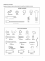
Hardware
Invenftoty
Separate all hardware and group as shown below for the assembly and installationprocedures,,
ASSEMBLY HARDWARE
Springfrrotley
Lock Nut
!/4"-20 (2)
Nut (t)
Nut
3/8" (I)
Lock Washer
3/8" (1)
Bolt 114"-20xt-314" (2)
_(!'!Ii((!(!((Ii((Ii(((((((((((((Iii(iIi
Master
Link (2)
Idiot Bol! (1)
Troltey Threaded Shaft (t)
INSTALLATION HARDWARE
©
Carriage Beff
_/4"-20xt t'2" (2)
©
Ring
Faslener (3)
Nut 5tt6"-18
(8)
Lock Washer
5116" (7)
Handle
_"_IitIil!llii!Ii_
Hex Beft
5/16"-18x7/8"
Lag Screw
5f16"_9x1-518" (2)
(4)
Insulated
Staples (30)
_l_I,F
r, i iiii]
5fl 6"-t 8xl-7/8"
Screw
6ABx1_l/4" (2)
(2}
_ding
Rope
Sc[ew
114"-94x5/8" (2)
Drywall Anchors (2)
Spacer (2)
o,_
C_evis Pin
5116"xl-1 f2" (t)
Clevis Pin
51I 6"xt" ('l)
Clevis Pin
51t 6"xl -1/4" (1}
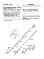
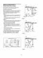
ASSEMBLY
Assemble
STEP
the
Rail
and
t
Install
the
Trolley
To prevent INJURYfrom pinching, keephands and fingers
awayfrom the jointswhileassemblingthe rail.
To avoid installation difficulties, do not run the garage
door opener until instructed to do so.
The front rail has a cut out "window" at the door end (see
illustration). The hole above this window is larger on
the top of the rail than on the bottom.. A smaller hole
3-1/2" (8.9 cm) away is close to the rail edge. Rotate the
back rail so it has a similar hole close to the opposite
edge, about 4-3/4" (!2 cm) from the far end.
3. Place the motor unit on packing material to protect
the cover, and rest the back end of the rail on top..
For convenience, put a support under the front end of
the rail..
1. Remove the straight door arm and hanging bracket
packaged inside the front rail and set aside for
Installation Step 5 and 12_ NOTE: To prevent INJURY
while unpacking the rail carefully remove the straight
door arm stored within the rail section.,
5. Check to be sure there are 4 plastic wear pads inside
the inner trolley.. If they became loose during shipping,
check all packing material. Snap them back into position
as shown..
I
I
I
4. As a temporary stop, insert a screwdriver into the hole
I0" (25 cm) from the front end of the rail, as shown..
6 Slide the trolley assembly along the rail from the back
end to the screwdriver..
2. Align the rail sections on a flat surface as shown and
slide the tapered ends into the larger ones., Tabs along
the side will lock into place.
Trolley
KEEP LARGER
HOLE ON TOP
End
lack Rails
(TO MOTOR UNIT)
End
8
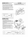
ASSEMBLY
Fasten
the
STEP
Rail
to
2
the
Motor
Unit
To avoid sERIOus damageto garagedoor opener,use ONLY
those be ts/fastenersmountedin the top of the opener..
* Insert a 1/4"-20xl-3/4 bolt into the cover protection bolt
hole on the back end of the rail as shown Tighten
securely with a 1/4"-20 lock nut. Do not overtighten.
o Remove the two bolts from the top of the motor uniL
, Place the "U" bracket, fiat side down, on the motor unit
and align the bracket holes with the bolt holes Fasten
with the previously removed bolts.
Motor Unit
Belt Pulley
/
° Align the rai! assembly with the top of the motor unit..
Slide the rail end onto the "U" bracket, all the way to the
stops that protrude on the top and sides of the bracket,
"U" Bracket
Boil
{ Cover
SLIDE RAiLTO STOPS
HARDWARE
SHOWN ACTUAL SIZE
OF BRACKET
ON
TOP AND StDES
Loc_kNu!
Bolt I14"-20xl-3!4"
ASSEMBLY
install
the
STEP
Idler
t/4"-20
3
Pulley
o Lay the belt beside the rail, as shown.. Grasp the end
with the hooked trolley connector and pass
approximately 12" (30 cm) of belt through the window,.
Keep the ribbed side toward the rail, and allow it to hang
until Assembly Step 5.
- Remove the tape from the idler pulley. The inside center
should be pre-greased If dry, regrease to ensure proper
operation,.
• Place the idler pulley into the window as shown..
Bolt
• Insert the idler bolt from the top through the rail and
pulley° Tighten with a 3/8" lock washer and nut
underneath the rail until the lock washer is compressed
- Rotate the pulley to be sure it spins freely.
• Insert a 1/4"-20xl-3/4 bolt into the trolley stop hole in
the front of the rail as shown. Tighten securely with a
1/4"-20 lock nut
Trolley
_--
Lock Washer
Inside
Pulley
Grease
_
Stop F_
Idler Pulley
_- Nut3,_"
,,,,,,_..
1
!
Y
Conneclor
I_
Pulley 1
HARDWARE
Idler Boll
SHOWN
Boll 114"-20xt-3/4"
ACTUAL
Lock
Nut
SIZE
Look Nut 1/4"-20
Nut 318"
Lock Washer 3.,'8"
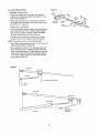
ASSEMBLY
install
the
Retainer
STEP
Belt
and
4
A_tach
the
Belt
Cap
To avoid possible SERIOUSiNJURYto fingers from moving
garagedoor opener:
- ALWAYSkeephand clear of belt pulleywhile
operatingopener,
• Securelyattach belt pulley cover BEFOREoperating
1. Pull the belt around the idler pulley and toward the
trolley, The ribbed side must contact the pulley.,
2, Hook the trolley connector into the retaining slot on the
trolley as shown,
3, With the trolley against the screwdriver, dispense the
remainder of the belt along the rail Iength toward the
motor unit and around the belt pulley., The belt pulley
teeth must engage the bell
4, Check to make sure the belt is not twisted and the
FLAT side of the trolley threaded shaft is facing the
rail,, Connect the trolley threaded shaft with the master
link, as illustrated:
HARDWARE SHOWN ACTUA L SIZE
• Push pins of master link bar through holes in end of
belt and trolley threaded shaft,,
o Push master link cap over pins and past pin notches.,
° Slide clip-on spring over cap and onto pin notches
until both pins are securely locked in place,
Hax Screw 8x3,"8°
Springrrrolley
5. insert the trolley threaded shaft through the hole in the
trolley,, Be sure the belt is not twisted and the FLAT
side faces the rail,,
6. Hold the belt at the trolley shaft as you thread the
spring nut by hand onto the shaft until finger tight
against the trolley_ Do not use any tools,.
7. Remove the screwdriver.,
Nut
Master Unk
C!tp-On Spdng
8, Position the belt cap retainer over the motor unit belt
pulley as shown and fasten to the mounting plate
with 8x3/8" hex screws provided,
Master Unk Cap
Pin
Trolley
Threaded
Shaft
._'_
Nolch 1
Master
Link Bar
Hole
Trolley
Conneclor
Idler PulIey
Retaining
Slot
8x3tS" Hex Screws
T
Bell Cap
Relatner
Motor Unit
_./Bell
Pulley
Mounling
10
ASSEMBLY
SeE the
STEP
5
Tension
J
, Insert a screwdriver tip into one of the nut ring slots and
brace it firmly against the trolley.,
o Place a 7/16" open end wrench on the square end_
Rotate the nut about 1/4 turn until the spring releases
and snaps the nut ring against the trolley..
This sets the spring to optimum belt tension..
You have now finished assembling your garage door
opener. Please read the following warnings before
proceeding to the instaflation section.
Trolley
Square
End
Nut Rinc
Nut Rin
INSTALLATllON
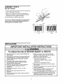
iMPORTANT
iNSTALLATiON
iNSTRUCTiONS
To reduce the risk of SEVERE iNJURY or DEATH:
1.,READANDFOLLOWALL INSTALLATIONWARNINGSAND
INSTRUCTIONS.,
8. NEVERwearwatches,rings or loose clothing white
installing or servicingopener,They could be caughtin
garagedoor or openermechanisms,,
9 Install walt-mountedgaragecontrol console:
• within sight of the garagedoor
• out of reachof childrenat minimum heightof
5 feet (1,5 m)
• awayfrom ALL moving parts of the door
I0 Placeentrapmentwarning label on wall next to garage
control console.
2.,Install garagedoor opener ONLYon properly balancedand
lubricatedgaragedoor, An improperlybalanceddoor may
not reversewhen required and could result in SEVERE
INJURYor DEATH
3,,ALL repairsto cables,spring assembliesand other
hardwareMUSTbe madeby a trained door systems
technician BEFOREinstalling opener.
4,,DisableALL locksand removeALL ropesconnectedto
garagedoor BEFOREinstalling openerto avoid
entanglement
5 Install garagedoor opener 7 feet (2,,1m) or more
abovefloor,,
6. Mount emergencyreleasehandle6 feet (1,8 m)
abovefloor..
7 NEVERconnectgaragedoor openerto power source until
instructedto do so
11_Placemanualrelease/safetyreversetest label in plain view
on inside of garagedoor,
I2 Upon completionof installation,test safety reversal
system°Door MUSTreverseon contact with a
1-1/2" (3,8 crn) high object (or a 2x4 laid flat) on the floor.
t3. To avoid SERIOUSPERSONALINJURYor DEATHfrom
electrocution,disconnect ALL electricand battery power
BEFORE
performing ANYserviceor maintenance.
11
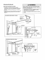
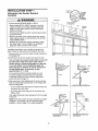
INSTALLATION
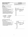
Determine
Location
the
STEP
Header
t
Bracket
CEILING
MOUNT
FOR
HEADER
BRACKET
Header Wall
Verticaf Centertine
of Garage Door
To prevent poss!bteSERIOUSINJURYor DEATH:
• HeaderbracketMUSTbe RIGIDLYfastenedto structural
support on headerwall or ceiling, otherwisegaragedoor
might not reversewhen required DONOTinstall header
bracketover drywall.
- Concreteanchors MUSTbe usedif mounting headerbracket
or 2x4 intomasonry.
• NEVERtry to loosen,move or adjust garagedoor, springs,
cables,pulleys,brackets,or their hardware,aff of which are
under EXTREMEtension.
2x4
Structural
Supports
Level
(optional)
• ALWAYScai]a trained door systemstechnicianif garage
door binds, sticks, or is out of balance.An unbalanced
garagedoor might not reversewhen required
Installation procedures vary according to garage door
types.. Follow the instructions which apply to your door..
1..Close the door and mark the inside vertical centertine of
the garage door,
2 Extend the line onto the header wall above the door..
You can fasten the header bracket within 4 feet (1.22
m) of the left or right of the door center only if a
torsion spring or center beating plate is in the way;
or you can attach it to the ceiling (see page t3)
when clearance is minimal. (It may be mounted on
the wall upside down if necessary, to gain
approximately 112" (1 cm)).
If you need to install the header bracket on a 2x4
(on wall or ceiling), use lag screws (not provided)
to securely fasten the 2x4 to structural supports as
shown here and on page t3
Header Waif
;-_-'-'- 2" (S cm) Track
Header Wali
Track
_Hilhelst Point
of Trave{
Z
Door
3. Open your door to the highest point of travel as shown.,
Draw an intersecting horizontal line on the header wall
above the high point:
nl
Sectiona! door with curved track
,, 2" {5 cm) above the high point for sectional door and
one-piece door with track..
One-piece door with horizontal track
• 8" (20 cm) above the high point for one-piece door
without track°
This height will provide travet clearance for the top edge
of the door°
_w_
_t _ _"(_0cm)
, ;"
NOTE: if the total number of inches exceeds the height
available in your garage, use the maximum height
possible, or refer to page I3 for ceiling installation,.
Door
I_',,_
I._.
_
_
_
Highest
Point
O,T_'.svel
I_"_
Door-_-_._
._;:"
,V"
',' Highest
,', Point
',ii:
°fTrave'
Hardware
_door
jamb hardware
12
without track:
One-piece door without track:
pivot hardware
mNSTALLATBON
STEP
Knstal#
Bracket
the
Header
2
Wall Mount
You can attach the header bracket either to the wall above
the garage door, or to the ceiling Follow the instructions
which wil! work best for your particular requirements., Do
not install the header bracket over drywall. If installing
into masonry, use concrete anchors (not provided).
WALL HEADER BRACKET INSTALLATION
Optional
Mounting Holes
o Center the bracket on the vertical centerline with the
bottom edge of the bracket on the horizontal line as
shown (with the arrow pointing toward the ceiling).,
Vertical
Centerlina
• Mark the vertical set of bracket holes.. DrilI 3/16" pilot
holes and fasten the bracket securely to a structural
support with the hardware provided,.
HARDWARE
Header
-- Wall
e DOOr
Lag Screws
5/16"xgx1-5/'8"
2x4
Struclural
Support
SHOWN ACTUAL SIZE
t
Hodzontal
,t,]ii i iiif,>
Une
i
.i j
T
Htghesl Point of
Garage Door Travel
Lag Screw
5/15"-9xt -5/8"
Vertical
Centerline
of Garage Door
CEILING HEADER BRACKET INSTALLATION
• Extend the vertical centefline onto the ceiling as shown,,
° Center the bracket on the vertical mark, no more than 6"
(15 cm) from the wall., Make sure the arrow is pointing
away from the watl. The bracket can be mounted flush
against the ceiling when clearance is minimal
- Mark the side holes., Drill 3/16" pilot holes and fasten
bracket securely to a structural support with the
hardware provided.,
Fintshed Ce_ting
. """_
.. _"
_
Vertical Centerftne
at Garage Door
Header "
Bracket
__
6" (I5 cm) Maximum
Ceiling Mounting Hales
@
-
Centerline
of Garage Door
13
Header Wall -
mHSTALLATION
Attach
the
STEP
Rail
to
the
3
Header
Bracket
NOTE: (Optional) With some existing installations, you
may re-use the old header bracket with the two plastic
spacers included in the hardware bag, Place the spacers
inside the bracket on each side of the rail, as illustrated
• Position the opener on the garage floor below the
header bracket Use packing material as a protective
base NOTEE'.ff the door spring is in the way, you will
need helpo Have someone hold the opener securely on
a temporary support to allow the rail to clear the spring
• Position the rail bracket against the header bracket
= Align the bracket holes and join with a clevis pin
as shown
Header Wall
• Insert a ring fastener to secure_
• Header Bracket
Idler Pulley
Bracket
Existing
Header Bracket
0
Spacer
Mounting
Hole
G arage
Door
OPTION WITH
SOME EXISTING
INSTALLATIONS
Opener Ca_on or
Suppo_
HARDWARE
SHOWN ACTUAL SIZE
0
Cle_s Pin 5tt 6"xt-1/2 _
14
Ring Fastener
UHSTALLATaOH
Position
the
STEP
4
Opener
To preventdamageto garagedoor, rest garage door opener
1
ra on 2x4 placedon top section of door,,
I
Follow instructions which apply to your door type as
illustrate&
SECTIONAL
DOOR OR ONE-PIECE
WITH TRACK
DOOR
A 2x4 laid flat is convenient for setting an ideal
door4o-rail distance,
- Remove foam packaging,
Rai_
i
° Raise the opener onto a stepladder. You will need help
at this point if the ladder is not tail enough,
• Open the door all the way and place a 2x4 laid fiat on
the top section beneath the rail.,
oor
_oe4ml_c_r;
Centdgmt
Ooudne_enrghi
negh '
o If the top section or panet hits the trolley when you raise
the door, pull down on the trolley release arm
to disconnect inner and outer sections Slide the outer
trolley toward the motor uniL The trolley can remain
disconnected until Installation Step 12 is completed.
_O__TtTtoltoy
Release Arm --_
ENGAGED
l
RELEASED \__j
ONE-PIECE DOOR WITHOUT TRACK
A 2x4 on its side is convenient for setting an ideal
door4o-raii distance.,
BrackNeader
• Remove foam packaging.,
- Raise the opener onto a stepladder. You will need help
at this point if the ladder is not tall enough.
o Open the door all the way and place a 2x4 on its side
on the top section of the door beneath the rail
r--
i
• The top of the door should be level with the top of the
motor unit,, Do not position the opener more than
4" (10 cm) above this poinL
15
2x4 is used to determine
the correct mounting height
from ceiling
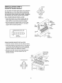
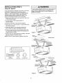
IHSTALLATIION
Hang
the
STEP
5
Opener
To avoid possible SERIOUSINJURYfrom a falling garagedoor
opener,fastenit SECURELY
to structural supports of the
garage.Concreteanchors MUSTbe usedif installing any
brackets into masonry.,
Three representative installationsare shown Yours may
be differenL Hanging brackets should be angled
(Figure 1) to provide rigid support, On finished ceilings
(Figures 2 and 3), attach a sturdy metal bracket to
structural supports before installingthe opener.. This
bracket and fastening hardware are not provided
1,,Measure the distance from each side of the motor unit
to the structural support..
2..Cut both pieces of the hanging bracket to
required lengths,
3 Drill 3/16" pilot holes in the structural supports..
4..Attach one end of each bracket to a support with 5/I6"18xl-7/8" lag screws.,
Boil
Lock Washer 5/16'
Nut 5/16"-t 8
5. Fasten the opener to the hanging brackets with
5/16"-18x7/8" hex bolts, lock washers and nuts.
6, Check to make sure the rail is centered over the door
(or in line with the header bracket if the bracket is not
centered above the dooO
7. Remove the 2x4_ Operate the door manually, If the door
hits the rail, raise the header bracket,.
NOTE: DO NOT connect power to opener at this time_
FINISHED
CEILING
Lag Screws
5/! 6'-18xl-7/8"
--"
Bolt 5/16"-1 8x7/8"
Lock Washer 5/16'
Bolt 5116"- t 8x7/8".
Lock Washer 5/16,t
HARDWARE
SHOWN ACTUAL SiZE
Nut 5/16"_
Figure 2
Lag Screws
Hex Bolt
5.tt 6"-18x7/8"
5/16"_18x1-7/8"
Nut 5116"-18
Lock Washer 5/t6"
_
.::_':
" " _-
Bolt 5116"-t 8x718"
Lock Washer 5/18'
Nut 5It 6"-1 8
Figure 3
16
_ "RNISHED
CEILING
.(Not P_ovided)
Bolt 5/16"-18x718"
Lock Washer 5/16 _
Nut 5116"-18
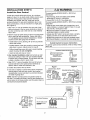
BNSTALLATiON
Insfall
t_e
STEP
Door
6
Contro/J
To preventpossibleSERIOUSIr_lJURYor DEATHfrom
electrocution:
Locate door control within sight of door, at a minimum
height of 5 feet (1,5 m) where small children cannot reach,
away from moving parts of door and door hardware.,
If installing into drywall, drill 5/32" holes and use the
anchors provided. For pre-wired installations (as in new
home construction), it may be mounted to a single gang
box (Figure 2).,
1 ,Strip 7/t6" (11 ram) of insulation from one end of bell
wire and connect to the two screw terminals on back of
the door control by color: white wire to 2 and white/red
wire to the 1.,
. DisconnectALL electric and battery power BEFORE
performingANYserviceor maintenance,
. ConnectONLYto 24 VOLTlow voltage wires.,
To preventpossibleSERIOUSINJURYor DEATHfrom a cfosing
garagedoor:
° Install the door control within sight of garagedoor, out of
reach of children at a minimum height of 5 feet (1.5 m), and
away fromALL moving pads of door
. NEVERpermit childrento operateor playwith the door
controf push buttons or remote controls.
- Activate door ONLYwhen it can be seendearly, is properly
adjusted,and there are no obstructions to door travel,
° ALWAYSkeepgaragedoor in sight until completely closed..
NEVERpermitanyoneto cross path of closing garagedoor.,
2, Remove cover by gently prying at slot in top of the cover
with a small flat head screwdriver, Fasten with 6ABx11/4" setf4apping screws (drywall installation) or 6-32xl"
machine screws (into gang box) as follows:
- install bottom screw, allowing 1/8" (3 mm) to protrude
above walt surface,
• Position bottom of the door control on screw head and
slide down to secure.. Adjust screw for snug fit.,
Outside Keylock Accessory Connections
To opener quick-connectterminals: white to white; white/
red to red.,
o Drill and install top screw with care to avoid cracking
plastic housing., Do not overtighten.
HARDWARE
• Insert top tabs and snap on cover•
3,,(For standard installation only) Run bell wire up wall
and across ceiling to motor unit° Use insulated staples
to secure wire in several places. Do not pierce wire with
a staple, creating a short or open circuit,,
the antenna
Screw 6_32x1"
(p_'e-wired)
Mounting
,_
_.,
Figure 2
MOUNT
PBE_WtRED 1NSTALLATION_
Tabs First
Push Bar Cover
_,[
Switch
Push Bar Cover_
_
Switch
To insert or release wi_o,
1 screwdriver tip
Terminal
Strip wi_e 7tl 6" (t 1 ram)
Screws
Bet!lll_.,---__"_lII Bottom
w_,. _
HMoOUnt,ng
(BACK VIEW)
WALL
To Replace
tnserl Top
lI_
Door Controi Connections
f - tJ] ,o,o
,,III
Drywall Anchors
Figure 1
STANDARD
6, Use tacks or staples to permanently attach entrapment
warning label to wall near door control, and manual
release/safety reverse test label in a prominent location
on inside of garage door,.
NOTE: DO NOT connect power and operate opener at
this time., The trolley will travel to the full open position but
will not return to the close position until the sensor beam is
connected and properly aligned,
IF" \_1-
SiZE
_ !i!l!illli*iiliHil
wire as shown,,
_Top
ACTUAL
(standard installation)
4. Strip 7/16" (11 mm) of insulation from end of bell wire,
Connect bell wire to the quick-connect terminals as
follows: white to white and white/red to red..
5, Position
SI-tOWN
i..................
17
/
_,OFF
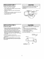
UtNISTALLATilON
Install
the
Battery
STEP
7
....
ALWAYSwear protective gtovesand eyeprotection when
changingthe battery or working around the battery
compartment.
-
Make sure motor unit is unplugged.
•
Using a Phillips head screwdriver,
cover on the motor unit.,
•
Partially insert battery into motor unit with terminals
facing out.
remove the battery
•
Connect the red (+) and black (-) wires from motor unit
to corresponding terminals on battery.
•
Replace
Batten]
Battery Cover
battery cover.,
gNSTALLATIION
Nnstali
;:i;::i
i :::i:::i _::b'::::¸
Backup
the
STEP
8
Lights
To preventpossible OVERHEATING
of the endpanelor light
socket:
o DONOTuseshort neck or specialtylight bulbs,.
• DONOTuse halogenbulbs,,Use ONLYincandescent,
To preventdamageto the opener:
• DONOTusebulbs largerthan IOOW.
• ONLYuseA19 size bulbs
• Press the release tabs on both sides of lens.. Gently
rotate lens back and downward until the lens hinge is in
the fully open position.. Do not remove the lens..
• Install a 100 watt maximum light bulb in each socket.
Light bulb size should be A19, standard neck only., The
lights wilt turn ON and remain lit for approximately
4-1/2 minutes when power is connected_ Then the lights
will turn OFF,.
!oo Watt (Max)
° Reverse the procedure to close the lens.,
o Llse A19, standard neck garage door opener bulbs for
replacement,
NOTE: Use only standard light bulbs,. The use of short
neck or speciality light bulbs may overheat the endpanel
or light socket°
Standard Light Bul_
/
Release Tab
I
1O0 Walt (Max)
Standard Ught Bulb
18
Hinge
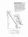
mNSTALLATl!OH
Attach
the
and Handle
STEP
Emergency
9
Release
Rope
To preventpossible SERIOUSINJURYor DEATHfrom a falling
garagedoor:
• If possible,use emergencyreleasehandleto disengage
trolley ONLYwhen garagedoor is CLOSEDWeak or broken
springs or unbalanceddoor could result in an open door
falling rapidlyand/or unexpectedly,
° NEVERuse emergencyreleasehandleunless garage
doorway is clear of persons and obstructions
° NEVERuse handleto pu_ldoor open or closed,,If rope knot
becomesuntied,you could fall,
• Thread one end of the rope through the hole in the top
of the red handle so "NOTICE" reads right side up as
shown. Secure with an overhand knot at least 1"
(2,,5 cm) from the end of the rope to prevent slipping
° Thread the other end of the rope through the hole in the
release arm of the outer trolley,,
° Adjust rope length so the handle is 6 feet (1 8 m) above
the floor., Ensure that the rope and handle clear the tops
of all vehicles to avoid entanglemenL Secure with an
overhand knot,
Trolley
NOTE: If it is necessary to cut the rope, heat seal the cut
end with a match or lighter to prevent unraveling,
!
,
Trol;ey
Release arm
19
Emergency -_
,,,_ Overhand
Release HandJe
,_Kn
ot
mNSTALLATmON
Elec*rical
STEP
t{)
Requirements
To prevent possibleSERIOUSINJURYor DEATHfrom
electrocutionor fire:
• DisconnectALL electricand battery power BEFORE
performing ANYserviceor maintenance,
• Garagedoor installationand wiring MUSTbe in compliance
with ALL localelectricaland building codes
• NEVERusean extensioncord, 2-wire adapter,or change
plug in any way to makeit fit out]eL Be sure the opener
is grounded
To avoid installation difficulties, do not run the opener
at this time.
To reduce the risk of electric shock, your garage door
opener has a grounding type plug with a third grounding
pin, This plug will only fit into a grounding type outlet, If
the plug doesn't fit into the outlet you have, contact a
qualified electrician to installthe proper outleL
PERMANF-NT
CONNECTION
If permanent wiring is required by your local code,
refer to the following procedure.
WIRING
Ground Tab
Green
Ground S_ew
To make a permanent connection through the 7/8" (2 cm)
hole in the top of the motor unit:
,, Remove the motor unit cover screws and set the cover
aside.,
Ground Wire
Wire
* Remove the attached 3-prong cord.
° Connect the black (line) wire to the screw on the brass
terminal; the white (neutral) wire to the screw on the
silver terminal; and the ground wire to the green ground
screw., The opener must be grounded,
° Reinstall the cover,
To avoid installation
at this time.
difficulties,
Black Wire
do not run the opener
2O
IHSTALLATmOH
Install
(Safety
STEP
The Protector
Sensors)
11
System
_
Be sure poweris NOTconnectedto the garagedoor opener
BEFOREinstalling the safety reversingsensor.
To preventSERIOUSINJURYor DEATHfrom a closing garage
door:
The safety reversing sensor must be connected and
aligned correctly before the garage door opener will
move in the down direction.
- Correctlyconnectand align the safety reversingsensor This
requiredsafety deviceMUSTNOTbe disabled,.
- Installthe safety reversing sensor so beamis NOHIGHER
than 6" (15 cm) abovegaragefloor.
IMPORTANT INFORMATION ABOUT
THE SAFETY REVERSING SENSOR
When properly connected and aligned, the sensor will
detect an obstacle in the path of its electronic beam.. The
sending eye (with an amber indicator light) transmits an
invisible light beam to the receiving eye (with a green
indicator light).. If an obstruction breaks the light beam
while the door is closing, the door will stop and reverse to
full open position, and the opener lights will flash 10 times..
If it is necessary to mount the units on the wall, the
brackets must be securely fastened to a solid surface such
as the wall framing.. Extension brackets (see accessories)
are available if needed. If installing in masonry
construction, add a piece of wood at each location to
avoid drilling extra holes in masonry if repositioning is
necessary..
The invisible light beam path must be unobstructed No
part of the garage door (or door tracks, springs, hinges,
rollers or other hardware) may interruptthe beam while
the door is closing.
The units must be installed inside the garage so that the
sending and receiving eyes face each other across the
door, no more than 6" (15 cm) above the floor.. Either can
be installed on the left or right of the door as long as the
sun never shines directly into the receiving eye lens..
The mounting brackets are designed to clip onto the track
of sectional garage doors without additional hardware..
I
Safety Reversing Sensor
6" (15 cm) max,
abov_ floor
Facing
the door from
Invisible Ught Beam
Prelectlan Area
inside the garage
21
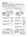
INSTALLING THE BRACKETS
Figure 1
Be sure power to the opener is disconnected. Instal]
and align the brackets so the sensors will face each other
across the garage door, with the beam no higher than 6"
(15 cm) above the floor.. They may be installed in one of
three ways, as follows..
Garage door track installation
DOORTRACK
L
MOUNT
(RIGHT
(RIGHT
SIDE)
SIDE)
Door
(preferred):
o Slip the curved arms over the rounded edge of each
door track, with the curved arms facing the door.. Snap
into place against the side of the track.. It should lie
flush, with the lip hugging the back edge of the track
(Figure 1)
rackel
If your door track will not support the bracket securely,
wall instaIlation is recommended.
Wall installation
Figure 2
WALL
MOUNT
(Figures 2 and 3):
- Place the bracket against the wall with curved arms
facing the door.. Be sure there is enough clearance for
the sensor beam to be unobstructed.
Fasten Wood Block to Wall with
(Not Provided)
Indicator
Ught
otf additional depth is needed, an extension bracket (see
Accessories) or wood blocks can be used
Sensor
° Use bracket mounting holes as a template to locate and
drill (2) 3/16" diameter pilot holes on the wall at each
side of the door, no higher than 6" (15 cm) above the
floor..
° Attach brackets to watt with lag screws (not provided)..
, if using extension brackets or wood blocks, adjust right
and left assemblies to the same distance out from the
mounting surface. Make sure all door hardware
obstructions are cleared..
Figure 3
WALL
MOUNT
(RIGHT
_tt
Floor installation (Figure 4):
° Use wood blocks or extension brackets
(see Accessories) to elevate sensor brackets so the
lenses will be no higher than 6" (15 cm) above
the floor..
i _
SIDE)
Bracket
(See Accessories)
: i
(Providedwilh
o Carefully measure and place right and left assemblies
at the same distance out from the wall Be sure all door
hardware obstructions are cleared..
° Fasten to the floor with concrete anchors as shown.
II1
_22
"_-
r._enslon
(Provide,
w'"L___
Extension =--_,,_" _
Bracket)
_
Figure 4
S_an_k°r
t
_
\
Indicator
Light
!
Lens
FLOOR
MOUNT(RIGHT
SIDE)
HARDWARE SHOWN ACTUAL SIZE
_
;
Carriage Be}It
t 14"-20xt/2"
Wing Nut
t/4"-20
Bracket)
tlach with
Concrete Anchors
(Not Provided)
Indicator
Light
Slaples
Bracket
22
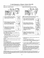
MOUNTING AND WIRING THE SAFETY
REVERSING SENSORS
Figure
5
• Slide a 1/4"-20xl/2" carriage bolt head into the slot on
each sensor.. Use wing nuts to fasten sensors to
brackets, with lenses pointing toward each other across
the door_ Be sure the lens is not obstructed by a bracket
extension (Figure 5)..
• Finger tighten the wing nuts,.
• Run the wires from both sensors to the opene[, Use
insulated staples to secure wire to wa!_and ceiling.,
TROUBLESHOOTING
THE SAFETY
REVERSING SENSORS
• Strip 7/16" (11 mm) of insulation from each set of wires.
Separate white and white/black wires sufficiently to
connect to the opener quick-connect terminals. Twist
like colored wires together,. Insert wires into
quick-connect holes: white to white and white/black
to grey (Figure 6).,
1. If the sending eye indicator light does not glow steadily
after installation, check for:
, Electric power to the opener.
- A short in the white or white/black wires.. These can
occur at staples, or at opener connections..
o Incorrect wiring between
= A broken wire..
ALIGNING THE SAFETY REVERSING SENSORS
o Plug in the opener. The indicator lights in both the
sending and receiving eyes will glow steadily if wiring
connections and alignment are correct,.
sensors and opener..
2.. If the sending eye indicator light glows steadily but the
receiving eye indicator light doesn't:
° Check alignment,
The sending eye amber indicator light will glow regardless
of alignment or obstruction,, If the green indicator light in
the receiving eye is off, dim, or flickering (and the invisible
light beam path is not obstructed), alignment is required.
= Check for an open wire to the receiving
3, If the receiving
sensor.,
• Loosen the sending eye wing nut and readjust, aiming
directly at the receiving eye,.Lock in place.
eye indicator
eye..
light is dim, realign either
NOTE: When the invisible beam path is obstructed or
misaligned while the door is closing, the door will reverse
If the door is already open, it will not close. The opener
lights will blink 10 times.. See page 21.
= Loosen the receiving eye wing nut and adjust sensor
until it receives the sender's beam. When the green
indicator light glows steadily, tighten the wing nut.,
Connecl V_re to
Quick_Connecl Terminals
Figure 6
Bell W_re
__
Finished
Ceiling
Bel_Wire
1 Slripwire
7116'
2. Twist like colored
wires together
3 To insert or release
wire, push in tab with
screwdriver lip
Safe_y Reversing
Sensor
Invisible LJghl Beam
Protection Area
Sa{ety Reversing
Sensor
23
Red White
Grey
Quick-Connect Terminals
BNSTALLATION
Fasten
_he Door
STEP
t 2
Bracket
Follow instructions which apply to your door type
as illustrated below or on the following page.
1
Fiberglass,aluminum or lightweightsteel garagedoors WILL
REQUIREreinforcementBEFOREinstallationof door bracket,
Contactyour door manufacturerfor reinforcementkit.
A horizontal reinforcement brace should be long
enough to be secured to two or three vertical
supports. A vertical reinforcement brace should cover
the height of the top panel.
Figure 1 shows one piece of angle iron as the horizontal
brace.. For the vertical brace, 2 pieces of angle iron are
used to create a U-shaped support.. The best solution is to
check with your garage door manufacturer for an opener
installation door reinforcement kit..
NOTE: Many door reinforcement kits provide for direct
attachment of the clevis pin and door arm. In this case .you
will not need the door bracket; proceed to Step !3
HORIZONTAL AND VERTICAL
_,- REINFORCEMENT IS NEEDED
FOR LIGHTWF_JGHT GARAGF,
DOORS (RBERGLASS,
ALUMINUM, STF_EL_DOORS
WITH GLASS PANEL_ ETC..).
{NOT PROVIDED}
SECTIONAL DOORS
1..Center the door bracket on the previously marked
vertical centerline used for the header bracket
installation.. Note correct UP placement, as stamped
inside the bracket..
of Gara!
Door
Figure 1
2. Position the top edge of the bracket 2"-4" (5-10 cm)
below the top edge of the door, OR directly below any
structural support across the top of the door.
Vortical
i(Not Provided)
Reinforcement
_l_Verticzd
[0]1_ HCenterline
Vedical
3,.Mark, drill holes and install as follows, depending on
your door's construction:
I
Reinfo_ement
_
Metal or light weight doors using a vertical angle iron
brace between the door panel support and the door
bracket:
(_
"_,,11°1_'1o_
Garage
Door
ertical
Cenlerline
of Gi_
= Drill 3/16" fastening holes. Secure the door bracket
using the two 1/4"-14x5/8" self4hreading screws
(Figure 2A).
° Alternately, use two 5/16" bolts, lock washers and nuts
(not provided) (Figure 2B)..
"
Door
Bracket "-"--_
LOck Washer _
5!t6"
Nut _' _,
UP
_.
5/16"-t8
Self-Threading --_
Screw
1/4"-14x5/8"
Metal, insulated or light weight factory reinforced
doors:
Figure
2B
Figure 2A
• Drill 3/16" fastening holes. Secure the door bracket
using the self-threading screws (Figure 3).
Wood Doors:
(Nol Provided)
tn_de Edge
_'etL_,rcOrmen ! Board
Bolt"P,.
. Use top and bottom or side to side door bracket holes..
Drill 5/16" holes through the door and secure bracket
with 5/16"x2" carriage bolts, lock washers and nuts (not
provided) (Figure 4)..
NOTE: The I/4"-14x5/8 ° self-threading screws are not
intended for use on wood doors°
_ISS/i
i
_Vertica|
Vertical -'1 _--,..,,..><(_
of Garage
Door
ARDWARE
SHOWN
"1, _S_'r_wThreading
I14"-t4x5/8"
ACTUAL SIZE
_f-Th_'eading
rew
Figure 3
"4 4x5/8"
24
Figure
4
ONE-PIECE DOORS
Please read and comply with the warnings and
reinforcement instructions on the previous page,. They
apply to one-piece doors also,,
= Center the door bracket on the top of the door, in line
with the header bracket as shown, Mark either the left
and right, or the top and bottom holes,
o Metal Doors: Drill 3/16" pilot holes and fasten the
bracket with the 1/4"-14x5/8" self-threading screws
provided,,
o Wood Doors: Drill 5/16" holes and use 5/16"x2"
carriage bolts, lock washers and nuts (not provided) or
5/'16"x1-1/2" lag screws (not provided) depending on
your installation needs,
HARDWARE SHOWN
ACTUAL StZE
Self-Threading Screw
t14"-14x5/8"
NOTE: The door bracket may be installed on the top edge
of the door if required for your installation., (Refer to the
dotted line optional placement drawing.)
Header Wall
2x4 Suppo_
Door
Bracket
METAL DOOR
Optional
Placement
of Door
Bracket
Vertical
Centedine o!
Garage
HORIZONTAL AND VERTICAL
REINFORCEMENT IS NEEDED
FOR LIGHTWEIGHT GARAGE
DOORS {FIBERGLASS,
ALUMINUM, STEEL, DOORS
wm-I GLASS PANEL, ETC,,),,
(NOT PROVIDED)
!
i
For a door with no exposed |raining,
or for the optionat installation, use
lag screws 5t16"x1-1/2" (Not Provided)
to {asten door bracket
25
WOOD
DOOR
UNSTALLATm(:)N
Connect
Door
STEP
Arm
to
13
Trolley
Follow instructions which apply to your door type as
illustrated below and on the following page
SECTIONAL DOORS ONLY
Make sure garage door is fully closed Pull the emergency
release handle to disconnect the outer trolley from the
inner trolley.. Slide the outer trolley back (away from the
pulley) about 8" (20 cm) (Figures 1, 2 and 3).
Figure 1:
- Fasten straight door arm section to outer trolley with the
5/16"xl" clevis pin. Secure the connection with a ring
fastener..
• Fasten curved section to the door bracket in the same
way, using the 5/16"x1-1/4" clevis pin..
Figure 1
Figure 2:
• Bring arm sections together.. Find two pairs of holes that
line up and join sections.. Select holes as far apart as
possible to increase door arm rigidity.
Pulley
Figure 3, Hole alignment alternative:
o If holes in curved arm are above holes in straight arm,
disconnect straight arm.. Cut about 6" (15 cm) from
the solid end., Reconnect to trolley with cut end down as
shown,.
- Bring arm sections
together.,
• Find two pairs of holes that line up and join with bolts,
lock washers and nuts,.
Pull the emergency release handle toward the opener at a
45 ° angle so that the trolley release arm is horizontal..
Proceed to Adjustment Step 1, page 28 Trolley will
re-engage automatically when opener is operated.
Bolts
Door Bracket
Figure 2
Pulley
HARDWARE
SHOWN
ACTUAL
©
©
Nut 5/t 6"-I 8
51t 6"xi" (Tro[iey)
SIZE
Lock Washer 5116'
Ring Fastener
5/16"x1-114" (Door Bracket)
Hex Bolt
5/16"qBxTfB"
Bolts
5115"-18x7/8"
Cut this end
Figure 3
26
ALL ONE-PIECE
1, Assemble
Figure 4
DOORS
the Door Arm:
Door
o Fasten the straight and curved door arm sections
together to the longest possible length (with a 2 or 3
hole overlap) (Figure 4)..
• Make sure the garage door is fully closed. Connect
the straight door arm section to the door bracket with
the 5/16"x1-1/4" clevis pin
oSecure with a ring fastener.
Doe_
o Pull the emergency release handle, disconnecting the
outer trolley from the inner trolley by pulling straight
down on the emergency release handle and sliding
the outer trolley back toward the motor unit..
• Connect the curved door arm section to the trolley
using the 5/t6"x1-1/4" clevis pin and ring fastener..
NOTE: Adjusting the limits on the following page:'
• The trolley will automatically connect., if not, review the
trolley lockout feature on page 33..
• When setting the up limit on the following page, the
door should not have a "backward" slant when fully
open as illustrated below.. A slight backward slant will
cause unnecessary bucking and/or jerking operation
as the door is being opened or closed from the fully
open position (Figure 5)..
Figure 5
Inner Trolley
L _ Closed
I
Emerge nc'j Release Handte
Door
Inner Trolley
(lncorrecl)
Open Door
27
Arm
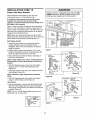
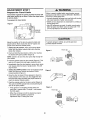
ADJUSTMENT
Program
the
STEP
Travel
1
Limits
Without a properlyinstalledsafety reversalsystem, persons
(particularlysmall children) could be SERIOUSLYINJUREDor
KILLEDby a closing garagedoor.
° Incorrect adjustmentof garagedoor travel limits will interfere
with proper operationof safetyreversal system,
=NEVERuseforce adjustmentsto compensatefor a binding or
sticking garagedoor_l
• After ANYadjustmentsare made, the safety reversalsystem
MUSTbe tested. Door MUSTreverseon contact with 1-1/2"
(3 8 cm) high object (or 2x4 laid flat) on floor,.
Travel limits regulate the points at which the door will
stop when moving up or down. Follow the steps below
to set the limits.
To program the travel limits:
Figure 1
°o
tndic_tor Ught
- Black Buttot_
- PurpleBlJtlon
To preventdamageto vehicles,be sure fully opendoor
providesadequateclearance,
Adjust the position of the door by using the black and
purple buttons.. Black moves the door UP (open) and
purple moves the door DOWN (close).
1..Setting the UP position: Press and hold the black
button until the yellow indicator light starts flashing
slowly then release,,
2oPush and hold the bIack button untit the door reaches
the desired UP (open) position (Figure 2)..
Indicator Ught
Figure 2
NOTE: Check to be sure the door opens high enough for
your vehicle..
3oPush the remote control or door control (Figure 3). This
sets the UP (open) limit and begins closing the door,.
"
until the door
Push
is
at desired
and hold
UP
posilion
4..Immediately when the door begins to move down, press
and release either the black or purple button.. This will
stop the door..
5 Setting the DOWN position: Push and hold the purple
button until the door reaches the desired DOWN
(closed) position (Figure 4),
6..Once the door is closed, if there appears to have too
much pressure on the door, you may toggle the door
back and forth using the black and purple buttons to
reach the desired closed position.
Figure 3
OR
7, Push the remote control or the door control (Figure 3)7
This sets the DOWN (close) limit and should bring the
door to the open position,,
Figure 4
- If the opener is not stopping exactly where you
would like it, repeat steps 1 through 7 and program
the limitsagain.
Indicator Ught
= When the unit stops in both the desired up (open)
and down (close) positions, proceed to
Adjustment Step 2, Setting the Force..
Push either
._
button toslop _,*-_.
doora,desiredll_l
DOWN position [J---_--
28
U
ADJUSTMENT
Se**ing
the
STEP
2
Force
Without a properlyinstalled safety reversalsystem, p_rsons
(particularlysmall children) could be SERIOUSLYiNJUREDor
KILLEDby a closing garagedoor.
. Too much force on garagedoor will interfere with proper
operationof safetyreversalsystem
=NEVERuseadfustmentsto compensatefor a binding or
sticking garagedoor_.
=After ANYadjustmentsare made, the safety reversalsystem
MUSTbe tested. Door MUSTreverseon contact with 1-1/2"
(3.8 cm) high object (or 2x4 laid flat) on floor,
The force setting button is located on the left panel of
the motor uniL The force setting measures the
amount of force required to open and close the door.
t.. Locate the purple button on the left panel of the motor
unit (Figure !),.
2. Push the purple button twice to enter the opener into
Force Adjustment Mode (Figure 1) The LED (Indicator
Light) will flash quickly..
3. Push the remote control or control console (Figure 2).
The door will travel to the DOWN (close) position. Push
the remote control or control console again, the door
will travel to the UP (open) position,. Push the remote
control or control console a third time to send the door
to the DOWN (close) position,
Figure I
The LED (Indicator Light) wil stop flashing when the force
has been learned.
The opener has learned the forces required to open and
close your door
The door must travel through a complete cycle, UP and
DOWN, in order for the force to be set properly. If the
opener cannot open and close your door fully, inspect
your door to insure that it is balanced properly and is not
sticking or binding. See page 3, "Preparing your
garage door."
0000
Indicator
Ught
Push Purple button
twice 1o enter
unit into Force
Adjustment Mode
Black
Button
Figure 2
OR
29
ADJUSTMENT
Test
the
Safety
STEP
3
Reversal
System
Without a properly installed safety reversatsystem, persons
(particularlysmall children) could beSERIOUSLYINJUREDor
KlLLEDby a closing garagedoor
• Safetyreversalsystem MUSTbe tested everymonth
° After ANY adjustmentsare made,the safety reversalsystem
MUSTbe tested, Door MUSTreverseon contact with t-t/2"
high (3 8 cm) object (or 2x4 laid flat) on the floor..
TEST
• With the door fully open, place a 1-1/2" (38 cm) board
(or a 2x4 laid flat) on the floor, centered under the
garage door,
= Operate the door in the down direction.. The door must
reverse on striking the obstruction
ADJUST
• if the door stops on the obstruction, it is not traveling far
enough in the down direction Complete Adjustment
Steps 1 and 2 Programming the Limits and Forces.
NOTE: On a sectional door, make sure limit adjustments
do not force the door arm beyond a straight up and
down position. See Figure 3, page 26.
• Repeat the tesL
• When the door reverses on the 1-1/2" (3.8 cm) board (or
2x4 laid fiat), remove the obstruction and run the opener
through 3 or 4 complete travel cycles to test adjustment,.
• tf the unit continues to fail the Safety Reverse Test, call
for a trained door systems technician
IMPORTANT SAFETY CHECK:
Test the Safety Reverse System after:
J
° Each adjustment of door arm length, limits, or force
controls..
= Any repair to or adjustment of the garage door
(including springs and hardware)..
o Any repair to or buckling of the garage floor..
12 (3 8 cm) board
(or a 2x4 laid flat)
° Any repair to or adjustment of the opener..
ADJUSTMENT
Test The Protector
(Safety
Sensors)
STEP
4
System
s
Without a properly installed safetyreversing sensor,persons
(particularly small children) could be SERIOUSLYINJUREDor
KILLEDby a closing garagedoor,
• Press the remote control push button to open the door
• Place the opener carton in the path of the door..
° Press the remote control push button to close the door.
The door will not move more than an inch (2.5 cm), and
the opener lights will flash..
%
|
The garage door opener will not close from a remote if the
indicatorlight in either sensor is off (alerting you to the fact
that the sensor is misaligned or obstructed)..
if the opener closes the door when the safety
reversing sensor is obstructed (and the sensors are
no more than 6" (15 cm) above the floor), call for a
trained door systems technician,
|
]
Safeb , Reversing Sensor
3O
Saiety Reversing
OPERATION
iiVtPORTANT SAFETY INSTRUCTnONS
To reduce the risk of SEVERE iNJURY or DEATH:
I. READANDFOLLOWALL WARNINGSAND INSTRUCTIONS.
2 ALWAYSkeepremote controls out of reachof children
NEVERpermit childrento operateor playwith garage
control console push buttons or remotecontrols
3. ONLYactivategaragedoor when it can be seen clearly,it is
properly adjusted,and there are no obstructionsto door
travel.
4 ALWAYSkeepgaragedoor in sight until completelyclosed
NO ONESHOULDCROSSTHE PATHOFTHE MOVING
DOOR.
5.. NOONESHOULDGO UNDERA STOPPED,PARTIALLY
OPENEDDOOR
6. if possible, useemergencyreleasehandleto disengage
trolley ONLYwhengaragedoor is CLOSEDWeak or broken
springs or unbalanceddoor could result in an open door
falling rapidlyand/or unexpectedly_
7 NEVERuseemergencyreleasehandle unlessgarage
doorway is clear of personsand obstructions..
8. NEVERusehandleto pull garagedoor open or closed. If
rope knot becomesuntied, you could fall
Using
Your
Garage
Door
9 tf one control (force or travel limits) is adjusted,the other
control may also needadjustment..
10..After ANYadjustmentsare made,the safety reversal
system MUSTbe tested..
11. SafetyreversalsystemMUSTbe tested every month
Garagedoor MUSTreverseon contactwith 1-I/2" high
(3.8 cm) object (or a 2x4 laid fiat) on the floor
12 ALWAYSKEEPGARAGEDOORPROPERLYBALANCED
(see page3). An improperiy balanceddoor may not
reversewhen requiredand could result in SEVEREINJURY
or DEATH.
13. ALL repairsto cables,spring assembliesand other
hardware,ALL of whichare under EXTREME
tension,
MUSTbe madeby a traineddoor systems technician.
I4 To avoid SERIOUSPERSONALINJURYor DEATHfrom
electrocution,disconnectALL electric and battery power
BEFOREperforming ANYserviceor maintenance.
SAVETHESEnNSTRUCTIONS.
6_If obstructed while opening, the door witl stop.
7. If fully open, the door will not close when the beam Es
broken.. The sensor has no effect in the opening cycle,
Opener
Your Security+ _ opener and hand-held remote control
have been factory-set to a matching code which changes
with each use, randomly accessing over 100 billion new
codes.. Your opener will operate with up to eight
Security,__ remote controls and one Security'l -_ Keyless
Entry System. If you purchase a new remote, or if you
wish to deactivate any remote, follow the instructions in
the Programming section..
If the sensor is not installed, or is misaligned, the door
won't close from a hand-hefd remote. However, you can
close the door with the control console, the Outside
Keylock, or Keytess Entry, if.you activate them until down
travel is complete_ tf you release them too soon, the door
will reverse..
The opener lights wilt turn on under the following
conditions: when the opener is initially plugged in; when
power is restored after interruption;when the opener is
activated..
Activate your opener with any of the following:
• The hand-hold Remote Control: Hold the large push
button down until the door starts to move..
• The wall-mounted control console: Hold the push
button or bar down until the door starts to move.
They will turn off automatically after 4-1/2 minutes or
provide constant light when the Light feature on the
Control Console is activated. Bulb size is 100 watts
maximum.
• The Keyless Entry (see Accessories):' If provided with
your garage door opener, it must be programmed
before use..See Programming.
Security*_ light feature: Lights will also turn on when
someone walks through the open garage door.. With a
Motion Detecting Door Control Console, this feature may
be turned off as follows: With the opener lights off, press
and hold the light button for 10 seconds, until the light
goes on, then off again., To restore this feature, start with
the opener lights on, then press and hold the light button
for 10 seconds until the light goes off, then on again
When the opener is activated (with the safety
reversing sensor correctly installed and aligned)
1. If open, the door will close.. If closed, it wilt open.
2 If closing, the door will reverse..
3. If opening, the door will stop°
4..If the door has been stopped in a partially open
position, it will close.
5. If obstructed while closing, the door will reverse.. If the
obstruction interrupts the sensor beam, the opener
lights will blink for five seconds.
31
Using
the
THE MOTION
Wall-Mounted
DETECTING
Door
CONTROL
Additional feature when used with the
3-button hand-heM remote
Control
To control the opener lights:
CONSOLE
Press the push bar to open or ctose the door.
Press again to reverse the door
Push
during the closing cycle or to
Bullon
stop the door while it's opening.
This door control contains a
motion detector that will
automatically turn on the light
when it detects a person entering
the garage.. This feature can be
/
easily turned off for extended
LOCl
Button
Ught
work light use.
Bulton
I..With the door closed, press and
hold a small remote button that you
want to control the lighL
2_Press and hold the Light button on the control console..
3. While holding the Light button, press and hold the Lock
button on the control console..
4. After the opener lights flash, release all buttons.
Dr
Light feature
Press the Light button to turn the opener light on or off.. It
will not control the opener lights when the door is in
motion.. If you turn it on and then activate the opener, the
light will remain on for 4-t/2 minutes_ Press again to turn it
off sooner. The 4-1/2 minute interval can be changed to
1-1/2, 2-1/2 or 3-I/2 minutes as follows: Press and hold
the Lock button until the light blinks (about 10 seconds). A
single blink indicates that the timer is reset to 1-1/2
minutes. Repeat the procedure and the light will blink
twice, resetting the timer to 2-1/2 minutes,. Repeat again
for a 3-I/2 minute interval, etc..,up to a maximum of four
blinks and 4-1/2 minutes..
When using the opener lights as working lights, we
recommend that you first disable the motion sensor See
Motion Detecting Light Feature, following.
Motion Detecting Light Feature: The opener light will
turn on automatically when a person walks in front of the
wai!-mounted control console. This feature works by
detecting motion and body heat and may not work in
temperatures around 100°F, 37._7C_The opener light will
come on for 5 minutes, then shut off automatically if no
additional motion or heat differential is calculated..
To disable this feature, slide the Detector Switch on the
right side of the door control down (off)..
We recommend that you disable the motion sensor when
using the opener lights as working lights.. Otherwise, they
will turn off automatically if you are working beyond the
sensor's range.,
Lock feature
Designed to prevent operation of the door from hand-held
remote controls_ However, the door will open and close
from the Door Control, the Outside Keylock and the
Keyless Entry Accessories_
To activate, press and hold the Lock button for 2 seconds..
The push bar light will flash as long as the Lock feature is
on,,
To turn off, press and hold the Lock button again for
2 seconds,The push bar light will stop flashing The Lock
feature will also turn off whenever the "Smart" (learn)
button on the motor unit panel is activated..
32
Care
Of Your
Opener
THE REMOTE CONTROL BATTERY
MAINTENANCE SCHEDULE
To preventpossible SERIOUSINJURYor DEATH:
• NEVERallow small children near batteries..
• If battery is swallowed,immediately notify doctor..
To reducerisk of fire, explosion or chemicalburn:
. ReplaceONLYwith 3V2032 coin batteries
• Do NOTrecharge,disassemble,heatabove100°C(212°F)
or incinerate..
Once a Month
• Manually operate door,. If it is unbalanced or binding,
call a trained door systems technician,.
• Check to be sure door opens and closes fully._Adjust
limits and/or force if necessary (see pages 28 and 29)
, Repeat the safety reverse test. Make any necessary
adjustments (see Adjustment Step 3)
Once a Year
• Oil door rollers, bearings and hinges. The opener does
not require additional lubrication.Do not grease the door
tracks,
The lithium battery should produce power for up to
5 years..
To replace battery, use the visor
clip or screwdriver blade to pry
open the case as shown., insert
battery positive side up (+)..
,'*'i_
Dispose of old battery properly.,
Replace the battery with only
3V2032 coin cell batteries..
II positive
up (+)
__
Batten/
NOTICE:To complywilhFCCand or Indust_ Canadarules (]C),adiuslmentor modiliralio_Isofthis
receiveran_or tmnsmilterare prohibited,exceptfor changingthe code settingor replacinothe
battery THEREARE NOOTHERUSERSERVICEAEILE
PARTS.
T0stedto Compiy wilh FCCS_andardsFDR HOMEOR OFFICEUSE,Operati0n is subjectto lho
following two conditions:
(1) tiffs device may no%_use harmtulintederence,.asd(2} this device
must acceptar_yInterferencereceived,includingintederenceIhat may r,:ausoundesiredopera_ion
TO Open
DISCONNECT
the
Door
Manually
THE TROLLEY:
To prevent possible SERIOUSINJURYor DEATHfrom a falling
garagedoor:
• If possible,use emergencyreleasehandleto disengage
trolley ONLYwhen garagedoor is CLOSED..
Weak or broken
springs or unbalanceddoor could result in an open door
falling rapidly andtor unexpectedly.
• NEVERuse emergencyreleasehandleunless garage
doorway is clearof persons and obstructions.
• NEVERuse handleto pull door open or closed.,If rope knot
becomesuntied,you could fall,
Trolley
The door should be fully closed if
possible,. Pull down on the
emergency release handle (so
that the trolley release arm snaps
into a vertical position) and lift the Trolley
door manually..The lockout
Release
Arm
feature prevents the trolley from
0nManua_
Disconnect
reconnecting automatically, and
Position}
the door can be raised and
lowered manually as often as
necessary.,
Lockout position
(Manual disconnect)
TO RE-CONNECT
TROLLEY:
THE
Pull the emergency release
handle toward the opener at an
angle so that the trolley release
arm is horizontal. The trolley will
reconnect on the next UP or
DOWN operation, either
manually or by using the control
console or remote..
Trolley
Trolley
Release
Arm
Emergency
Release Handle
0
To reconnect
33
Battery
Backup
OPERATING INSTRUCTIONS
To reducethe risk of FIREor INJURYto persons:
• DisconnectALL electricand batterypower BEFORE
performingANYserviceor maintenance.
° Use onlyChamberlainpart #4IA6357-! for replacement
battery_
• Do NOTdispose of batteryin fire. Batterymay explode.
Checkwith focal codes for disposal instructions.
1.Test the installed battery with the motor unit.
To test the battery, disconnectthe motor unit power cord
from the electrical outlet.
• A solid orange LED indicates the battery is operating on
battery power..
• A flashing orange LED with beep indicates the unit is
operating on battery power and that the battery charge
is low..
° To test the battery is functioning properly, open and
close the garage door.
° Re-connect the motor unit power cord back into the
electrical outlet.
, Verify that the green LED is flashing on the BBU
(indicates that the battery is now charging)
Batlery Slalus LED
• Test completed..
2. Charge the battery.
• Battery will take 24 to 48 hours to fully charge.
A fully charged battery supplies 12V DC to the motor unit
for one to two days of normal operation during an
electrical power outage.. If the battery voltage drops too
low, the batteries will disconnect and the motor unit witi no
longer operate under battery power..
NOTE: LED is most visible with worklight
GREEN LED:
All systems
are normal
• A solid LED light indicates
After the electricaf power has been restored, the battery
will recharge within 48 hours. Under normal usage
batteries wilt last 3 to 5 years_
o A flashing
off,
the battery is fully charged,
LED indicates the battery is being charged°
NOTE: Battery does not have to be fully charged
operate the motor unit_,
To obtain maximum battery life and prevent damage,
disconnect the battery when motor unit is unplugged
for an extended period of time.
to
ORANGE LED:
The motor unit has lost power and is operating off of the
battery.
° A solid LED with beep, sounding approximately every 2
seconds, indicates the motor unit is activating the door
and is operating off of the battery.
- A flashing LED with beep, sounding every 30 seconds,
indicates battery is low.
NOTE: Door operation may be limited until battery is fully
charged.. The motor unit's lights will not turn on during
battery mode..
• Once the power is restored the battery will recharge..
This is indicated by a flashing green LED..
RED LED:
• If a red LED remains on when the power is restored,
and is accompanied by a beep sounding every 30
seconds, please call for service.,
• To obtain maximum battery life and prevent damage,
also disconnect the battery if you unplug the motor
unit while on vacation or any other extended period
of time..
34
Having
a Problern?
(TroubHeshooting)
1. My door will not close and the light bulbs blink on
my motor unit: The safety reversingsensor must be
connected and aligned correctly before the garage door
opener will move in the down direction_
Bell Wire
- Verify the safety reversing sensors are properly
installed, aligned and free of any obstructions.,Refer
to installation Step ! 1 Install The Protector Systen_
- Check diagnostic LED for flashes on the motor unit
then refer to the Diagnostic Chart on the following
page
2 My remotes will not activate the door:
- Verify your Motion Detecting Control Console is not
blinking If it is blinking deactivate the Lock Mode
following the instructions for Using the Wall Mounted
Door Control
Reprogram remotes following the programming
instructions Refer to Programming
Sending Eye Salety
Reversing Sensor
(Amber indicator Ugh1)
If remote will still not activate your door check
diagnostic LED for flashes on motor unit then refer to
Diagnostic Chart on the following page
3. My door reverses for no apparent reason: Repeat
safety reverse test after adjustments to force or travel
limits The need for occasional adjustment for the force
and limit settings is normal Weather conditions in
particular can affect door travel
Receiving Eye
Safely Reversing Sensor
(Green indicator Light)
6 My motor unit hums briefly:
• First verify that the trolley is against the stop bolt
o Release the door from the opener by pulling the
Emergency Release Rope
o Manually check door for balance or any binding
problems
° Manually bring the door to a closed position
° Loosen the belt by adjusting the outer nut 4 to 5 turns
This relieves the tension
° Run the motor unit from the remote control or control
console The trolley should travel towards the door
and stop If the trolley reengages with the door pul!
the Emergency Release Rope to disengage
. Refer to Adjustment Step 2, Adjust the Force
4. My door reverses for no apparent reason after fully
closing and touching the floor: Repeat safety reverse
test after adjustments to force or travel limits. The need
for occasional adjustment for the force and limit settings
is normal., Weather conditions in particular can affect
door travel,.
T[olle
• Refer to Adjustment Step 1, Adjust the UP and DOWN
Travel Limits..
5. My lights will not turn off when door is open:
_"_
. The garage door opener is equipped with a security
light feature° This feature activates the light on when
the safety reversing sensor beam has been
obstructed Refer to Operation section; Using the Wall
Mounted Door Control, Light Feature
t-1f4"
(3 18 cm)
• Re-Tighten the outer nut until the trolley spring is
approximately I-1/4" (3,,18 em) in length,
• If the trolley does not move away from the bolt, repeat
the steps above,,
7. Battery status LED is not lit properly:
• Check battery connections,,
35
Safety Reversing Sensor
Diagnostic
Your garage door opener is programmed
with self-diagnostic
capabilities
The "Learn" buttorJdiagnostic
LED will flash a
number of times then pause signifying it has found a potential
issue Consult Diagnostic Chart below.
Charf
Safety reversing sensors
wire open (broken
or disconnected).
OR
0 Symptom: One or both of the Indicator lights on the safety reversing sensors
do not glow steady.
* inspect sensor wires for a short (staple in wire), correct wiring polarity (black/white
wires reversed), broken or disconnected wires, replace/attach as needed
- Disconnect alI wires from back of motor unit
o Remove sensors from brackets and shorten sensor wires to 1-2 ft (30-60 cm) from
back each of sensor_
Safety reversing sensors
wire shorted or black/
white wire reversed.
o Reattach sending eye to motor unit using shortened wires, If sending eye indicator
light glows steadily, attach the receiving eye
. Align sensors, if the indicator lights glow replace the wires for the sensors, If the
sensor indicator lights do not light, replace the safety reversing sensors,
0 Symptom: LED is not lit on door control
Door control or wire
shorted,
• Inspect control console/wires for a short (staple in wire), replace as needed,
- Disconnect wires at door control, touch wires together If motor unit activates,
replace door control.
- If motor unit does not activate, disconnect door control wires from motor unit
Momentarily short across red and white terminals with jumper wire If motor unit
activates, replace door control wires
0 Symptom: Sending indicator fight glows steadily, receiving indicator fight is
dim or flashing.
Safety reversing sensors
slightly misaligned (dim
or flashing LED).
• Realign receiving eye sensor, clean lens and secure brackets,
= Verify door track is firmly secured to wall and does not move
0 Symptom: RPM Sensor = Short travel 6-8" (15-20 cm).
Possible RPM sensor
failure. Unplug to reset.
. Unplug unit to reset Try to operate motor unit, check diagnostic code.
- If it is still flashing 5 times and motor unit moves 6-8" (15-20 cm), replace
RPM sensor
• If motor unit doesn't operate, motor unit is overheated_ Wait 30 minutes and retry,
If motor unit still wilt not operate replace logic board,
36
PROGRAMMRNG
NOTICE: if this Security't ,_ garage door opener is operated with a non-rolling code remote control the technical
measure in the receiver of the garage door opener, which provides security against code-theft devices, will be
circumvented.
The owner of the copyright in the garage door opener does not authorize the purchaser or supplier
non-rolling code remote control to circumvent that technical measure.,
Your garage door opener has already been programmed at the factory to operate with your hand-held
The door will open and close when you press the large push button,
Below are instructions
for programming
To
USING THE "LEARN"
Add
your opener to operate with additional
or Reprogram
a Hand.held
1,, Press and release the "learn" button on
the motor unit., The learn indicator light
will glow steadily for 30 seconds,
Remote
Control
DETECTING
DOOR
2,, White holding the remote button, press
and hold the LIGHT button on the
Motion Detecting Door Control,
.. I
3, Continue holding both buttons while
you press the push bar on the Motion
Detecting Door Control (all three
buttons are held),
/
4o Release buttons when the motor unit
lights blink It has learned the code, If
light bulbs are not installed, two clicks
will be heard..
To
Erase
All Codes
From
Unit Memory
Motor
*3.Button
_.___
I
I
"_ ![--It I
]
I _
I
]
I _::A::qlI
I
_f(
}_ J
]
k__ 1./
Remotes
(315
..,I
/
MHz)
If provided with your garage door opener, the large button
is factory programmed to operate it.. Additional buttons on
any Security÷ ® 3-button
.t"_/__,._
_
remote or mini-remote can
be programmed to operate
other Security÷ e garage
,
To deactivate any unwanted remote, first
erase all codes:
.
Press and held the learn" button on motor
unit until the learn indicator light goes out
(approximately 6 seconds)° Alt previous
codes are now erased, Reprogram each
remote or keyless entry you wish to use.
CONTROL
I. Press and hold the button on the
hand-held remote* that you wish to
operate your garage door,
2. Within 30 seconds, press and hold the
button on the hand-held remote* that
you wish to operate your garage door.,
3. Release the button when the motor unit
lights blink., It has learned the code, If
light bulbs are not installed, two clicks
will be heard,,
remote control,,
Security.I ,° 315 MHz remote controls.
USING THE MOTION
BUTTON
of the
I
t
I
J
t
I
doo
37
I
7"o Add,
Reprograrn
or C_ange
a Keyless
EnEry
PIN
NOTE: Your new Keyless Entry must be programmed to operate your garage door opener,
USING THE "LEARN"
BUTTON
USING THE MOTION
1.. Enter a four digit personal identification
number (PIN) of your choice on the
keypad.. Then press and hold ENTER,.
2. Within 30 seconds, enter a four digit
personal identification number (PIN) of
your choice on the keypad. Then
press and hold the ENTER button.
2. While holding the ENTER button,
press and hold the LIGHT button on
the Motion Detecting Door Control.
3. Release the button when the motor
unit lights biink., it has learned the
code If light bulbs are not installed,
two clicks will be heard.,
known
CONTROL
NOTE: This method requires two people if the Keytess
Entry is already mounted outside the garage,.
1..Press and release the "learn" button
on motor uniL The learn indicator light
will glow steadily for 30 seconds..
To change an existing,
DETECTING
3
PIN
4,,
If the existing PIN is known, it may be changed by one
person without using a ladder..
1..Press the four buttons for the present PIN, then press
and hold the # button..
Continue holding the ENTER and
LIGHT buttons while you press the
push bar on the Motion Detecting Door
Control (all three buttons
are held)..
Release buttons when the motor unit
lights blink_ It has learned the code.. If
light bulbs are not installed, two clicks
will be heard,.
The opener light will blink twice. Release the # button
2.. Press the new 4-digit PIN you have chosen, then
press Enter.
2o Press the temporary 4-digit PIN you have chosen, then
press Enter,
The motor unit lights will blink once when the PIN has been
learned..
The opener light will blink four times
Test by pressing the new PiN, then press Enter., The door
should move,
To set a temporary
3.,To set the number of hours this temporary PIN will work,
press the number of hours (up to 255), then press :I:.
OR
PIN
You may authorize access by visitors or service people with
a temporary 4-digit PIN. After a programmed number of
hours or number of accesses, this temporary PIN expires
and will no longer open the door.. It can be used to close the
door even after it has expired_ To set a temporary PIN:
3..To set the number of times this temporary PIN will work,
press the number of times (up to 255), then press #..
The opener light will blink once when the temporary PIN has
been learned
Test by pressing the four buttons for the temporary PIN,
then press Enter. The door should move. If the temporary
PiN was set to a certain number of openings, remember
that the test has used up one opening, To clear the
temporary password, repeat steps 1-3, setting the number
of hours or times to 0 in step 3o
1..Press the four buttons for your personal entry PIN (not
the last temporary PIN), then press and hold the =I=
button..
The opener light will blink three times, Release the
button..
One Button Close: Opener can be closed by pressing onty the ENTER button if the one button close feature has been
activated. This feature has been activated at the factory. To activate or deactivate this feature press and hold buttons 1 and 9
for 10 seconds. The keypad will blink twice when the one button close is active. The keypad will blink four times when one
button close is deactivated.
38
REPAiiR
PARTS
4
41 B4t03
Spring
5
144C54
Idler pulley
6
4tA5250
Full belt assembly
7
41 D598-1
"U" bracket
trolley nut
NOT SHOWN
183A163
Installation
Wear pads
Paris
4
KEY
NO.
PART
NO.
1
41c472-7
2
3
4
953D
10A20
29B137
5
6
41 A2828
41 B4494-1
41A5047-t
7
8
9
41A5047-3
41A5034
t0
tl
178B34
12
t3
41A5266-1
178B35
41A6357-t
I
39
DESCRIPTION
Motion detecting control console
3-Button remote control
3V2032 Lithium battery
Remote control visor clip
Emergency release rope and handle assembly
2-Conductor bell wire, white and white/red
Door bracket w clevis pin & fastener
Header bracket w/clevis pin & fastener
Safety reversing sensor kit (receiving and
sending eyes) with 3' (,9 m) 2-conductor
bell wire
Straight door arm section
Curved door arm section
Safety reversing sensor brackets (2)
Battery
NOT SHOWN
41A5257-10
Installation hardware bag (includes
hardware listed on page 7)
12B776
114A3282
Hanging brackets
Owners manual
114A3282SP
Owner's manual - Spanish
Motor
Unit
Assembly
Parts
11
KEY
NO.
PART
NO.
1
41 c76
2
3
4
4t B4245
41 B4375-3
41A628t
41A6282
41 A6327
41A6328
5
6
41D794
41DB002-2
KEY
NO,
DESCRIPTION
Belt cap and sprocket
Line cord
Terminal block with screws
Wire harness kit Complete with:
Battery wires and plug
Light socket wires and plug
RPM/passpoint wires with plug
Motor with travel module
Receiver logic assembly
40
PART
NO.
7
41A6231
8
DESCRIPTION
41C190
End panel with battery door
and screw
Transformer and harness
9
10
41D504_5
Cover
108D79
11
175B88
Light lens
Light socket
41A6357-1
NOT SHOWN
Battery kit
ACCESSORIES
77020B
953D
Outside Quick Release:
Required for a garage with NO access
door_
760CB
%
8808CB
SECURITY,I
,® Remote
Includes visor ctip_
956D
Outdoor Key Switch:
Operates the garage door automatically
from outside when remote control is not
handy,,
3-Button Mini-Remote Control
with SECURITY,I-®:
With key ring and fastening strip,.
940D
8 Foot (2,4 m) Rail Extension:
To allow an 8 foot (2,,4 m) door to open
fully.,
8810CB
3-Button
Control:
SECURITY,! ,®Keyless Entry:
Enables homeowner to operate
garage door opener from outside by
entering a password on a specially
designed keyboard,, Also can add a
temporary password for visitors or
service persons,, This temporary
password can be limited to a
programmable number of hours
or entries,
10 Foot (3 m) Rail Extension:
To allow a 10 foot (3 m) door to
open fully..
CLDM1
Garage
Door Monitor:
Monitors the status of your garage
door from inside your home,,
41A5281
Extension Brackets:
(Optional) For safety reversingsensor
installation onto the wall or floor., To order
call: 1-800-528-9131,.
CLLAD
Remote Light Control:
Enables homeowner to turn on a lamp,
television or other appliance from their
car with their garage door opener remote
or from anywhere in their home with an
additional Chamberlain Security+ ®
remote.,
41
HOTES
42
NOTES
43
CHAMBERLAIN" SERVICE
ON CALL
IS
OUR LARGE SERVICE ORGANIZATION
SPANS AMERICA
INSTALLATION
AND SERVICE INFORMATION
IS AS NEAR
AS YOUR TELEPHONE., SIMPLY DIAL OUR
TOLL FREE NUMBER:
HOW TO ORDER
REPAIR PARTS
Selling prices will be furnished on request, or parts wil! be
shipped at prevailing prices and you wili be billed accordingly,
WHEN ORDERING REPAIR PARTS, ALWAYS GIVE THE
FOLLOWING INFORMATION:
* PART NUMBER
1-800-528-9131
" PART NAME
" MODEL NUMBER
ADDRESS ORDERS TO:
THE CHAMBERLAIN GROUP, INC
Technical Support Group
6050 S, Country Ctub Road
Tucson, Arizona 85706
www.ch amberlain-diy,,com
For professional installation, parts and service, contact
your local CHAMBERLAIN" dealer_ Look for him in the Yellow
Pages, or call our Service number for a list of dealers in your
area.
SERVICE INFORMATION
TOLL FREE NUMBER:
1-800-528-913'1
CHAMBERLAIN ®ONE-YEAR LIMITED WARRANTY
10 YEAR BELT LIMITED WARRANTY & LIFETIME MOTOR LIMITED WARRANTY
The Chamberlain Group, lnc (=Seller") warrants to the first retail purchaser of this product, for the residence in which this product is originatfy
installed, that it is free from defect in materials and/or workmanship for a pedod of one year from the dale of purchase, [and that the bett is free
from defect in materials and/or workmanship for a period of 1!3years from the date of purchase and that the motor is free from defect in materials
and!or workmanship for the lifetime of the product]. The proper operation of this product is dependent on your compliance with the instructions
regarding installation, operation, maintenance and testing.. Failure to comply strictly with those instructions will void this limited warranty in its
entirely..
If, during the limited warranty period, this product appears to contain a defect covered by this limited warranty, call 1-800-52B-9131, toll tree,
before dismantling this product. Then send this product, pro-paid and insured, to our service center for warranty repair. You will be advised of
shipping instructions when you call Please include a brief description of the problem and a dated proof-of-purchase receipt with any product
returned for warranty repair. Products returned to Seller for warranty repair, which upon receipt by Seller are confirmed to be defective and
covered by this limited warranty, will be repaired or replaced (at Seiter's sote option) at no cost to you and returned pro-paid.. Defective parts wiiI
be repaired or replaced with new or factory-rebuift paris at SelIer's soie option.
ALL IMPLIED WARRANTIES
FOR THE PRODUCT,
INCLUDING
BUT NOT LIMITED TO ANY IMPLIED WARRANTIES
OF MERCHANTABILITY
AND FITNESS
FOR A PARTICULAR
PURPOSE,
ARE LIMITED
IN DURATION
TO THE ONE YEAR LIMITED
WARRANTY
PERIOD SET
FORTH ABOVE [EXCEPT THE IMPLIED WARRANTIES
WITH RESPECT TO THE BELT AND MOTOR,
WHICH ARE LIMITED IN DURATION
TO THE BELT 10 YEARS
AND MOTOR
LIFETIME
LIMITED
WARRANTY
PERIOD FOR THE BELT AND MOTOR],
AND NO IMPLIED
WARRANTIES
WILL EXIST OR APPLY AFTER SUCH PERIOD.
Some states do not allow limitations
on how long an implied
warranty
lasts_ so the above limitation
may not apply to you. THIS LIMITED WARRANTY
DOES NOT COVER NON-DEFECT
DAMAGE,
DAMAGE
CAUSED
BY IMPROPER
INSTALLATION,
OPERATION
OR CARE (INCLUDING,
BUT NOT LIMITED
TO ABUSE_ MISUSE,
FAILURE
TO
PROVIDE
REASONABLE
AND NECESSARY
MAINTENANCE,
UNAUTI-]OR|ZED
REPAIRS
OR ANY ALTERATIONS
TO THIS PRODUCT),
LABOR CHARGES
FOR REINSTALLING
A REPAIRED
OR REPLACED
UNIT, REPLACEMENT
OF BATTERIES
AND LIGHT BULBS OR
UNITS INSTALLED
FOR NON-RESIDENTIAL
USE.
THIS LIMITED
WARRANTY
DOES NOT COVER ANY PROBLEMS
WITH, OR RELATING
TO, THE GARAGE
DOOR OR GARAGE
DOOR
HARDWARE,
INCLUDING
BUT NOT LIMITED
TO THE DOOR SPRINGS,
DOOR ROLLERS,
DOOR
ALIGNMENT
OR HINGES_ THIS
LIMITED
WARRANTY
ALSO
DOES NOT
COVER
ANY
PROBLEMS
CAUSED
BY INTERFERENCE..
ANY SERVICE
CALL
THAT
DETERMINES
THE PROBLEM
HAS BEEN CAUSED
BY ANY OF THESE ITEMS COULD RESULT
IN A FEE TO YOU.
UNDER NO CIRCUMSTANCES
SHALL SELLER
BE LIABLE FOR CONSEQUENTIAL,
INCIDENTAL
OR SPECIAL
DAMAGES
ARISING tN
CONNECTION
WITH USE, OR INABILITY
TO USE_ THIS PRODUCT.
IN NO EVENT SHALL SELLER'S
LIABILITY
FOR BREACH
OF
WARRANTY,
BREACH
OF CONTRACT_
NEGLIGENCE
OR STRICT
LIABILITY
EXCEED
THE COST OF THE PRODUCT
COVERED
HEREBY.
NO PERSON
IS AUTHORIZED
TO ASSUME
FOR US ANY OTHER
LIAB1LFr,/
IN CONNECTION
WITH THE SALE OF THIS
PRODUCT.
Some states do not altow the exclusion or [imitationof consequential, incidental or special damages, so the above limitation or exclusion may not
apply to you,. This limited warranty gives you specific legal rights,and you may also have other rights which vary from state to stale..
t14A3282E
© 2009, The Chamberlain
Group,
AU Rights Reserved
Inc.