1
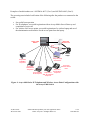
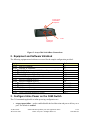
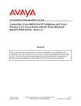
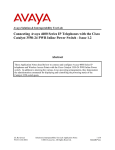
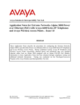
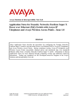
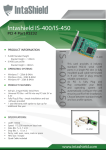
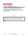
Avaya Solution & Interoperability Test Lab
Connecting Avaya 4600 Series IP Telephones and
AvayaWireless Access Points with the Avaya C460
Converged Multilayer Switch using Power over Ethernet
(PoE) - Issue 1.0
Abstract
These Application Notes describe how to configure inline power for Avaya 4600 Series IP
Telephones and Avaya Wireless Access Points with the Avaya C460 Converged Multilayer
Switch. The various Avaya powering arrangements are shown and the administration
commands for displaying and controlling the powering status of the switch ports are
demonstrated.
JZ; Reviewed:
WCH 9/23/2003
Solution & Interoperability Test Lab Application Notes
©2003 Avaya Inc. All Rights Reserved.
1 of 8
C460-PoE.doc
1. Introduction
Power over Ethernet (PoE) is a feature offered on several Ethernet switches. It allows the switch
to supply power to a network device within the same CAT-5 cable that carries the Ethernet
signaling. This simplifies network installation and powering design, removing the need for a
separate power supply for each IP telephone in the network. IEEE 802.3af defines a standard
protocol to be used by powering and powered devices. Avaya 4600 Series IP telephones, Avaya
wireless LAN access point products, and the Avaya C460 Converged Multilayer Switch comply
with this standard.
The Avaya C460 Switch Release 2.0 introduces new PoE I/O modules and a 1000 W Power
Supply Unit (PSU) to support PoE. The Avaya C460 Switch can support up to 4 slots with PoE
modules and 3 1000W PSUs to support PoE. The PoE module provides power feeding for up to
48 Fast Ethernet ports with up to 15.4 Watts with 48V per port over Category 3, 5, or 6 cabling.
The two new PoE modules are:
•
•
M4638ML-T-PWR – C460 Multilayer 48 X 10/100 BaseT (RJ-45) inline power module
M4638ML-T-2G-PWR – C460 Multilayer 48 X 10/100 BaseT (RJ-45) + 2 x GBIC (SFP)
inline power module
The Avaya product configurations addressed by these Application Notes are shown in Figure 1.
The following Avaya products are directly connected to the switch:
•
•
•
•
•
4602 and 4602SW IP Telephones
Gen-2 4606, 4612 and 4624 IP Telephones
4620 IP Telephone (including the optional EU24 Button Expansion Module)
4630SW IP Screenphone
AP-3 (v2 model), AP-4 and AP-5 Access Points.
Note that only version 2 AP-3 models support PoE interface. A visual indicator to tell a "v1" vs.
"v2" AP-3 is that the "v1" has a mini-din serial connector and the "v2" has a male DB9 serial
connector. Version 1 AP-3 models will not work with the C460 PoE module.
The Gen-1 Avaya™ 4612 and 4624 IP Telephones require the Avaya™ 30A Switch Base.
Figure 2 shows the connections for the 30A switch base. The 4612 and 4624 telephones can be
identified as Gen-1 or Gen-2 by inspecting the model number. “1A” in the model number
indicates Gen-1; “2A” indicates Gen-2. The model number can be found by:
•
Inspecting the label attached to the bottom of the telephone.
OR
•
Pressing Mute, V, I, E, W, # on the keypad and then pressing * until the model number
appears. Press # to exit.
JZ; Reviewed:
WCH 9/23/2003
Solution & Interoperability Test Lab Application Notes
©2003 Avaya Inc. All Rights Reserved.
2 of 8
C460-PoE.doc
Examples of model numbers are “4612D01A-003” (Gen-1) and 4612D02A-003 (Gen-2).
The powering tests included verification of the following after the product was connected to the
switch:
•
•
•
Successful boot operation
For IP telephones, successful registration with an Avaya Media Server/Gateway and
completion of a test call
For wireless LAN access points, successful registration of a wireless laptop and use of
the administration web interface for the access point from the laptop.
Avaya C460
Switch
Avaya AP4
Access Point
Avaya AP 5
Access Point
Wireless
Laptop
Avaya AP 3 (V2)
Access Point
Avaya 4602,
4602SW IP
Telephones
Avaya 4620,
4620-EU24 IP
Telephones
Avaya Gen-1
4612 & 4624 IP
Avaya 4630SW
Avaya Gen-2
Telephones
IP Screenphone 4606, 4612, 4624 IP
Telephones
Avaya 30A
Ethernet Switch
Base
Figure 1: Avaya 4600 Series IP Telephone and Wireless Access Point Configurations with
the Avaya C460 Switch
JZ; Reviewed:
WCH 9/23/2003
Solution & Interoperability Test Lab Application Notes
©2003 Avaya Inc. All Rights Reserved.
3 of 8
C460-PoE.doc
To line jack of
4612/4624 IP
Telephone
To PC
To ethernet
switch port
Figure 2: Avaya 30A Switch Base Connections
2. Equipment and Software Validated
The following equipment and software were used for the sample configuration provided:
Equipment
AvayaTM 4602 IP Telephone
AvayaTM 4602SW IP Telephone
AvayaTM 4620 IP Telephone with EU24 Button Expansion Module
AvayaTM 4630SW IP Screenphone
AvayaTM 4606 IP Telephone (Gen-2)
AvayaTM 4612 IP Telephone (Gen-1, Gen-2)
AvayaTM 4624 IP Telephone (Gen-1)
AvayaTM 4624 IP Telephone (Gen-2)
AvayaTM AP-3 Access Point (v2 model)
AvayaTM AP-4 Access Point
AvayaTM AP-5 Access Point
AvayaTM 30A Ethernet Switch Base
AvayaTM C460 Converged Multilayer Switch
Software
1.7
1.7
1.794
1.8
1.73
1.73
1.73
1.8
2.1.2(412)
2.1.1(403)
2.1.1(375)
2.0.2
3. Configure Inline Power on the C460 Switch
The CLI commands applicable to inline powering configuration are:
•
set port powerinline – used to enable/disable the load detection and power delivery on a
port. The default is enabled.
JZ; Reviewed:
WCH 9/23/2003
Solution & Interoperability Test Lab Application Notes
©2003 Avaya Inc. All Rights Reserved.
4 of 8
C460-PoE.doc
•
•
set port powerinline priority – used to set the priority of the port to be powered to
Low, High or Critical. The default is Low.
set powerinline budget – used to force the supervisor module to recalculate and to
reapply the PoE budget to the I/O modules. This command may reset the switch.
Steps
1.
•
Description
Enable PoE on port 6/1.
C460-2(configure)# set port powerinline 6/1 enable
Load detection process on port 6/1 is enabled.
2.
•
Set port 6/1 inline power priority to high.
C460-2(configure)# set port powerinline priority 6/1 high
Powering priority on port 6/1 was set to High.
3.
•
Recalculate and reapply Main and PoE power budget.
C460-2(configure)# set powerinline budget
This command may RESET the device
*** May cause reset *** - do you want to continue (Y/N)? y
The power budget in the chassis was redistributed.
4. Verification Steps
The CLI commands applicable to verify inline powering status are:
•
•
•
show powerinline – used to display the current state of the inline power.
show powerinline budget – used to display the PoE budget distribution for modules in
the switch
show environment power – used to provide PoE information.
Steps
1.
•
Description
Display the inline power status.
C460-2(super)# show powerinline
Port
Admin
Detection
Status
Status
------ -------- -----------------6/1
Enabled
Delivering Power
6/2
Enabled
Delivering Power
6/3
Enabled
Delivering Power
...
JZ; Reviewed:
WCH 9/23/2003
Maintenance
Status
-----------Ok
Ok
Ok
Solution & Interoperability Test Lab Application Notes
©2003 Avaya Inc. All Rights Reserved.
Powering
Priority
--------High
Low
Low
5 of 8
C460-PoE.doc
Steps
2.
•
•
Description
Display PoE budget distribution.
The PoE module M4648ML-T-2G-PWR is located in slot 6. In this example, the PoE budget
is 620W for slot 6, of which 20W is currently being used.
C460-2(super)# show powerinline budget
Slot
---3
4
5
6
3.
•
•
Module Type
--------------------------M4612ML-G
M4648ML-T-2G
Budget
-----N/A
N/A
Demand
-----N/A
N/A
620W
20W
M4648ML-T-2G-PWR
Display PoE system information.
In this example, the total power drawn from one 1000 W PSU is 1000 W (380W + 620W).
The main system (Modules + Fans) gets 380W budget and the PoE module gets 620W
budget. Avaya 4620, Avaya AP-3 and AP-5 were connected to ports 6/1-3 respectively. A
total of 20 watts have been used for these devices. 600W for the PoE remains. 380 W for the
main system have been used:
68W (slot 1: SPV) + 68W (slot 2: SPV) + 59W (slot3: M4612ML-G) + 70W (slot 4:
M4648ML-T-2G) + 70W (slot6: M4648ML-T-2G-PWR) + 45W (Fans) = 380 W
C460-2(super)# show environment power
PSUs Configuration Admin: redundancy
PSUs Configuration State: no redundancy (1 active PSU(s))
Power
----Main
PoE
Slot
---1
2
3
4
5
6
Available
--------380W
620W
Drawn
----380W
20W
Module Type
---------------M460ML-SPV
M460ML-SPV
M4612ML-G
M4648ML-T-2G
M4648ML-T-2G-PWR
Remaining
--------0W
600W
Active
-----Y
Y
Y
Y
N
Y
Enabled
------Y
Y
Y
Y
Y
Y
Priority
-------critical
critical
low
low
low
low
Main
Draw
---68W
68W
59W
70W
0W
70W
PoE
Budget
------
PoE
Draw
----
620W
20W
* Fans power consumption: 45(W)
JZ; Reviewed:
WCH 9/23/2003
Solution & Interoperability Test Lab Application Notes
©2003 Avaya Inc. All Rights Reserved.
6 of 8
C460-PoE.doc
Faul
----
5. Conclusion
The following Avaya IP telephone and wireless access point products were tested with the Avaya
C460 Switch, and were successfully powered:
•
IP telephones:
• 4602 and 4602SW
• 4620, including EU24 Button Expansion Module
• 4630SW
• Gen-1 4612 and 4624 with 30A switch base
• Gen-2 4606, 4612, and 4624
•
Wireless access points
• AP-3 (v2 model)
• AP-4
• AP-5
Avaya IP telephones, Avaya wireless access points, and the Avaya C460 Switch are designed to
the IEEE 802.3af standard. These Application Notes have described the interconnection of IP
telephones, AP-3 (v2) Access Point, AP-4 Access Point and AP-5 Access Point with the Avaya
C460 Switch, as well as status and control commands for the switch.
JZ; Reviewed:
WCH 9/23/2003
Solution & Interoperability Test Lab Application Notes
©2003 Avaya Inc. All Rights Reserved.
7 of 8
C460-PoE.doc
©2003
Avaya Inc. All Rights Reserved.
Avaya and the Avaya Logo are trademarks of Avaya Inc. All trademarks identified by ® and ™
are registered trademarks or trademarks, respectively, of Avaya Inc. All other trademarks are the
property of their respective owners. The information provided in these Application Notes is
subject to change without notice. The configurations, technical data, and recommendations
provided in these Application Notes are believed to be accurate and dependable, but are
presented without express or implied warranty. Users are responsible for their application of any
products specified in these Application Notes.
Please e-mail any questions or comments pertaining to these Application Notes along with the
full title name and filename, located in the lower right corner, directly to the Avaya Solution &
Interoperability Test Lab at [email protected]
JZ; Reviewed:
WCH 9/23/2003
Solution & Interoperability Test Lab Application Notes
©2003 Avaya Inc. All Rights Reserved.
8 of 8
C460-PoE.doc