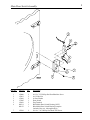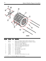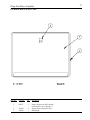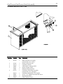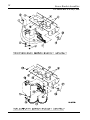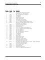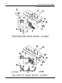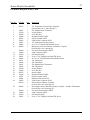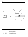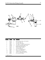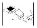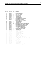
1
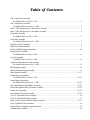
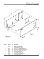
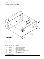
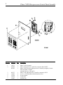
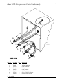
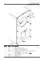
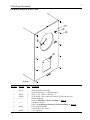
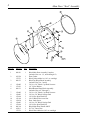
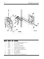
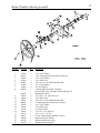
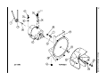
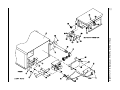
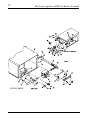
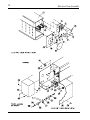
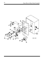
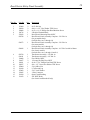
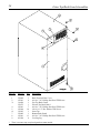
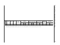
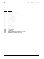
D-30
Parts Manual
JLA Limited
Meadowcroft Lane, Halifax Road
Ripponden
West Yorkshire, England
HX6 4AJ
Telephone: 01422 822282 / Fax: 01422 824390
031102JCARRITA/rmoles
ADC Part No. 450589
Retain This Manual In A Safe Place For Future Reference
J.L.A. products embody advanced concepts in engineering, design, and safety. If this product is properly maintained, it will
provide many years of safe, efficient, and trouble free operation.
ONLY qualified technicians should service this equipment.
OBSERVE ALL SAFETY PRECAUTIONS displayed on the equipment or specified in the installation manual included with
the dryer.
The following “FOR YOUR SAFETY” caution must be posted near the dryer in a prominent location.
FOR YOUR SAFETY
POUR VOTRE SÉCURITÉ
Do not store or use gasoline or
other flammable vapors and
liquids in the vicinity of this or
any other appliance.
Ne pas entreposer ni utiliser d’essence
ni d’autres vapeurs ou liquides
inflammables à proximité de cet
appareil ou de tout autre appareil.
We have tried to make this manual as complete as possible and hope you will find it useful. J.L.A. reserves the right to make
changes from time to time, without notice or obligation, in prices, specifications, colors, and material, and to change or
discontinue models.
Important
For your convenience, log the following information:
DATE OF PURCHASE ____________________________
D-30
MODEL NO. __________________________________________
RESELLER’S NAME _______________________________________________________________________________________
Serial Number(s)
________________________________________________________________________________________
________________________________________________________________________________________
________________________________________________________________________________________
Replacement parts can be obtained from your reseller or J.L.A. When ordering replacement parts, you can FAX your order
to J.L.A. at 01422 824390 or telephone your order directly to the J.L.A. Parts Department at 01422 822282. Please specify the
dryer model number and serial number in addition to the description and part number, so that your order is processed
accurately and promptly.
The illustrations on the following pages may not depict your particular dryer exactly. The illustrations are a composite of the
various dryer models. Be sure to check the descriptions of the parts thoroughly before ordering.
“IMPORTANT NOTE TO PURCHASER”
Information must be obtained from your local gas supplier on the instructions
to be followed if the user smells gas. These instructions must be posted in a
prominent location near the dryer.
Table of Contents
OPL Control Door Assembly
For Models Mfd. as of July 1, 2002 .................................................................................................. 2
OPL Control Door Assembly
For Models Mfd. prior to July 1, 2002 .............................................................................................. 3
Phase 7 OPL Microprocessor Control Panel Assembly ........................................................................... 4
Phase 7 OPL Microprocessor Control Box Assembly ............................................................................. 5
Front Panel Assembly
For Models Mfd. as of July 1, 2002 .................................................................................................. 6
Front Panel Assembly
For Models Mfd. prior to July 1, 2002 .............................................................................................. 7
Main Door “Steel” Assembly .................................................................................................................. 8
Main Door Switch Assembly................................................................................................................... 9
Basket (Tumbler)/Support Assemblies ................................................................................................... 10
Drop Lint Door Assembly
For Models Mfd. as of July 1, 2002 .................................................................................................11
Lint Trap Assembly
For Models Mfd. as of July 1, 2002 ................................................................................................ 12
Lint Drawer/Lint Drawer Switch Assembly
For Models Mfd. prior to July 1, 2002 ............................................................................................ 13
Idler Bearing Assembly ......................................................................................................................... 14
Basket (Tumbler) Bearing Assembly ...................................................................................................... 15
Motor Mount Assembly .................................................................................................................. 16, 17
Sensor Bracket Assemblies
For Models Mfd. as of July 1, 2002 .......................................................................................... 18, 19
Sensor Bracket Assemblies
For Models Mfd. prior to July 1, 2002 ...................................................................................... 20, 21
Direct Spark Ignition (DSI) Burner Assembly .................................................................................. 22, 23
Hot Surface Ignition (HSI) Gas Burner Assembly ............................................................................ 24, 25
Electric Oven Assembly .................................................................................................................. 26, 27
Rear Electric Relay Panel Assembly ................................................................................................ 28, 29
S.A.F.E. Temperature Probe Assembly ................................................................................................. 30
S.A.F.E. Solenoid and Piping Assembly ................................................................................................ 31
Steam Coil/Air-Operated Steam Damper Assembly ........................................................................ 32, 33
Outer Top/Back Guard Assemblies ....................................................................................................... 34
Electrical Oven Component Application Chart ....................................................................................... 35
Additional Parts Available ..................................................................................................................... 36
2
OPL Control Door Assembly
For Models Mfd. as of July 1, 2002
Illus. No.
Part No.
Qty.
1
883574
1
2
3
4
5
6
7
8
150321
117604
150317
102502
154011
102603
102601
2
4
2
1
2
1
1
Description
White OPL Control Door
(includes illus. nos. 1 and 3)
#10-32 x 1/2” Phillips Machine Screw
Neoprene Sponge Tape (sold by the foot)
#10-16 x 3/4” TORX + BTN Type 1
Control Door Support Rod
#10-32 Multi-Thread U-Nut
Control Door Rod Support Catch
Control Door Retainer Clip
OPL Control Door Assembly
For Models Mfd. prior to July 1, 2002
Illus. No.
*
Part No.
Qty.
1
883294
1
2
3
4
5
150314
117604
--------*
154011
4
2
1
4
Contact reseller for logo.
Description
White Control Door Assembly
(includes illus. nos. 1 and 3)
#10-32 x 1/2” TORX + BTN
Noise Suppressor Tape (sold by the foot)
Logo
#10-32 Multi-Thread U-Nut
3
4
Phase 7 OPL Microprocessor Control Panel Assembly
Illus. No.
Part No.
Qty.
1
2
112571
850984
883301
1
1
1
3
4
5
6
7
883277
150005
153010
136016
136097
1
2
2
1
1
Description
Phase 7 OPL Keyboard
Phase 7 Microprocessor Controller (computer) Panel ONLY
Phase 7 OPL Reversing Microprocessor Controller (computer) Control
Panel Assembly Complete
(includes illus. nos. 1 through 7)
Phase 7 OPL Microprocessor Controller (computer) ONLY
#6-32 x 3/4” Phillips Round Head Machine Screw
#6 Star Washer
5-Amp Fuse
500 mA Fuse
Phase 7 OPL Microprocessor Control Box Assembly
Illus. No.
1
2
3
4
5
6
7
*
Part No.
122681
122676
122646
122683
122640
122706
122669
As needed.
Qty.
1
1
1
1
1
*
*
Description
10-Pin Connector
8-Pin Connector
2-Pin Connector
6-Pin Terminal
9-Pin Terminal
#20-16 U.M.N.L. Socket
Female Crimp Terminal
5
6
Front Panel Assembly
For Models Mfd. as of July 1, 2002
Illus. No.
Part No.
Qty.
1
883567
1
2
3
150313
150318
--------
11
1
1
4
5
6
122002
170330
154215
1
1
2
Description
White Front Panel Assembly
(includes illus. nos. 1, 3, and 5 through 6)
#10-16 x 1/2” TORX + BTN Type 1
25 IP TORX + Bit 1/4 Hex (for removal of TORX head screw)
Main Door Hinge
(refer to Main Door “Steel” Assembly on page 8)
Lint Drawer Switch
Friction Door Latch
5/32” Pop Rivet
7
Front Panel Assembly
For Models Mfd. prior to July 1, 2002
Illus. No.
Part No.
Qty.
1
883137
1
2
3
150313
150318
--------
11
1
1
4
--------
1
5
881987
1
6
154215
2
Description
White Front Panel Assembly
(includes illus. nos. 1, 3, and 5 through 6)
#10-16 x 1/2” TORX + BTN Type 1
25 IP TORX + Bit 1/4 Hex (for removal of TORX head screw)
Main Door Hinge
(refer to Main Door “Steel” Assembly on page 8)
Lint Drawer Switch
(refer to Lint Drawer/Lint Drawer Switch Assembly on page 13)
Friction Door Latch Kit
(includes illus. nos. 5 and 6)
5/32” Pop Rivet
8
Main Door “Steel” Assembly
Illus. No.
Part No.
Qty.
1
881150
1
2
3
102354
170731
881152
1
1
1
4
5
6
150445
153031
881151
2
1
1
7
8
9
10
11
12
13
14
15
150445
150683
152014
151010
150120
150683
152014
881210
102211
170731
2
3
3
1
1
3
3
1
1
1
Description
Black Main Door Assembly Complete
(includes illus. nos. 1, 2, and 8 through 15)
Door Gasket
Black Gasket Adhesive (10.3 oz. cartridge)
Black Top Hinge Block Assembly
(includes illus. nos. 3 and 4)
1/4-20 x 3/4” Black Cap Head Setscrew
1/4” Nylon Washer
Black Bottom Hinge Block Assembly
(includes illus. nos. 5 through 7)
1/4-20 x 3/4” Black Cap Head Setscrew
1/4-20 x 5/8” Black Carriage Bolt
1/4-20 Free Spin Wash Nut
#10-32 Black Hex Acorn Nut
Door Latch Screw
1/4-20 x 5/8” Black Carriage Bolt
1/4-20 Free Spin Wash Nut
Black Main Door Handle ONLY
20-7/16” Door Glass
Black Glass Adhesive (10.3 oz. cartridge)
Main Door Switch Assembly
Illus. No.
Part No.
Qty.
1
2
3
4
5
6
150006
152013
153010
137005
122636
881211
881153
2
2
2
1
2
1
1
7
150301
2
Description
#6-32 x 7/8” Phillips Pan Head Machine Screw
#6-32 Hex Nut
#6 Star Washer
Door Switch
Flag Terminal
Black Main Door Switch Housing ONLY
Black Main Door Switch Housing Complete
(includes illus. nos. 1 through 4 and 6)
#8-18 x 7/16” Phillips Pan Head TEK Screw
9
10
Basket (Tumbler)/Support Assemblies
Illus. No.
*
Part No.
Qty.
1*
800776
883295
1
1
2
3
4
5
6
7
8
9
10
11
--
150313
301420
150518
100914
153004
817084
152005
153005
153004
116002
401010
24
4
1
4
4
1
4
4
4
1
1
Description
Stainless Steel Basket (tumbler) ONLY (without felt collar)
Stainless Steel Basket (tumbler)/Support Assemblies Complete
(includes illus. nos. 1 through 10)
#10-16 x 1/2” TORX + BTN Type 1
Stainless Steel Basket (tumbler) Rib ONLY
5/16-18 x 3/8” Socket Button Head Screw
3/8-16 x 20” Tie Rod
3/8” Flat Washer
Basket (tumbler) Support ONLY
3/8-16 Hex Nut
3/8” Lock Washer
3/8” Flat Washer
Felt Collar ONLY
#847 Adhesive for Felt Collar (5.0 oz. tube)
Felt collar is not included and must be ordered separately.
Drop Lint Door Assembly
For Models Mfd. as of July 1, 2002
Illus. No.
Part No.
Qty.
1
802277
1
2
3
117604
170226
5
1
Description
Drop Lint Door (for OPL models)
(includes illus. nos. 1 through 3)
Sponge Tape (sold by the foot)
Slide Latch
11
12
Lint Trap Assembly
For Models Mfd. as of July 1, 2002
Illus. No.
Part No.
Qty.
1
800401
1
2
3
4
5
800443
154200
150300
304100
800500
1
6
3
1
2
Description
Lint Trap Assembly Complete
(includes illus. nos. 1 and 3 through 5)
Lint Trap ONLY
5/32” Pop Rivet
#10-16 x 1/2” Hex Washer TEK Screw
Lint Screen Holder ONLY
Lint Screen Assembly
Lint Drawer/Lint Drawer Switch Assembly
For Models Mfd. prior to July 1, 2002
Illus. No.
Part No.
Qty.
1
883140
1
2
3
4
5
6
117605
122116
122605
122701
122801
833123
5
1
1
4
1
1
7
8
9
304136
150301
122700
122604
1
2
4
1
Description
White Lint Drawer Assembly
(includes illus. nos. 1 and 2)
Gasket (sold by the foot)
Lint Drawer Switch
4-Pin Socket Connector ONLY
Socket Terminal ONLY
Pin/Socket Extraction Tool
Lint Drawer Switch Box Assembly
(includes illus. nos. 3 through 6)
Lint Drawer Switch Box Cover ONLY
#8-18 x 7/16” Phillips Pan Head TEK Screw
Pin Terminal ONLY
4-Pin Connector ONLY
13
14
Idler Bearing Assembly
Illus. No.
Part No.
Qty.
1
2
3
4
5
6
100107
101129
100103
154301
100705
882576
1
1
1
2
1
1
7
8
9
10
11
12
150617
153005
153004
801009
152004
150509
2
2
2
1
1
1
Description
5L-670 V-Belt (basket [tumbler] to idler)
9” x 2-1/2” Compound Pulley
4L-510 V-Belt
5/16-18 x 1” Allen Setscrew
3/16” x 3/16” x 1-3/8” Key
Idler Bearing Assembly Complete
(includes illus. nos. 5 through 12)
3/8-16 x 1” Hex Head Machine Bolt
3/8” Lock Washer
3/8” Flat Washer
Idler Square Washer
5/16-18 Hex Nut
5/16-18 x 3” Hex Head Machine Bolt
Basket (Tumbler) Bearing Assembly
Illus. No.
Part No.
Qty.
1
2
3
4
5
6
7
8
153002
880213
153002
152004
150501
153002
153004
883609
3
1
3
3
4
4
4
1
9
10
11
12
13
14
15
16
17
18
19
20
21
801105
150610
152004
150501
880201
153002
152004
101100
154301
100713
100107
319004
883386
102120
1
2
2
3
1
3
3
1
2
1
1
1
1
1
Description
5/16” Lock Washer
1-1/4” Flange Bearing with Nylock Setscrew
5/16” Lock Washer
5/16-18 Hex Nut
5/16-18 x 3/4” Hex Head Machine Bolt
5/16” Lock Washer
3/8” Flat Washer
1” Bearing Box Assembly Complete
(includes illus. nos. 8 through 14 and 19 through 21)
Bearing Box ONLY
5/16-18 x 1-1/2” Allen Setscrew
5/16-18 Hex Nut
5/16-18 x 3/4” Hex Head Machine Bolt
1” Flange Bearing with Nylock Setscrews
5/16” Lock Washer
5/16-18 Hex Nut
18” Pulley ONLY
5/16-18 x 5/16” Setscrew
1/4” x 1/4” x 7/8” Key
5L-670 V-Belt (basket [tumbler] to idler)
Rotational Sensor Bracket
Rotational Sensor Assembly
Rotational Sensor Magnet
15
16
Motor Mount Assembly
Motor Mount Assembly
Illus. No.
1
2
3
4
5
6
7
8
9
10
11
12
13
14
15
16
17
18
19
20
Part No.
Qty.
100103
100705
101131
1
1
1
101133
1
150501
153002
153001
181049
4
4
4
1
100066
1
122701
122801
137030
152004
153002
153001
117604
154000
850017
817076
8
1
1
4
4
4
4
4
1
1
153050
100604
100702
153050
152006
2
1
1
2
2
17
Description
4L-510 V-Belt (motor to idler)
3/16” x 3/16” x 1-3/8” Key
1/2” x 2-1/4” Motor Pulley
(for models mfd. as of August 22, 2002)
5/8” x 2-1/4” Motor Pulley
(for models mfd. prior to August 22, 2002)
5/16-18 x 3/4” Hex Head Machine Bolt
5/16” Lock Washer
5/16” Flat Washer
1/2 HP 240v 1ø 50 Hz Plug-Type Motor
(for models mfd. as of August 22, 2002)
1/2 HP 240v 1ø 50 Hz Totally Enclosed, Fan-Cooled (T.E.F.C.) Plug-Type
Motor
(for models mfd. prior to August 22, 2002)
Socket Terminal ONLY
Pin/Socket Extraction Tool
8-Pin Housing Connector
5/16-18 Hex Nut
5/16” Lock Washer
5/16” Flat Washer
Neoprene Sponge Tape (sold by the foot)
5/16-18 Tinnerman Nut
1/2 HP Motor Mount ONLY (56Z frame)
1/2 HP 240v 1ø 50 Hz Motor Mount Assembly Complete with Plug Motor
(includes illus. nos. 2 through 7 and 13 through 20)
1/2” S.A.E. Flat Washer
12-1/2” Impellor with 1/2” Bore
1/8” x 1/8” x 1-1/2” Key
1/2” S.A.E. Flat Washer
1/2-20 Left Hand Jam Nut
18
Sensor Bracket Assemblies
For Models Mfd. as of July 1, 2002
Sensor Bracket Assemblies
19
For Models Mfd. as of July 1, 2002
Illus. No.
Part No.
Qty.
1
880251
1
2
3
4
5
6
7
8
9
10
130301
153010
152000
121028
122701
122605
154007
150005
801424
1
2
2
2
4
1
2
2
1
11
12
13
14
15
16
17
18
19
20
21
22
23
24
305007
122604
122700
150301
150005
130111
130100
130103
130101
153010
152000
840065
121028
122701
122605
818007
1
1
4
2
5
1
1
1
1
5
5
1
8
4
1
1
25
818321
1
305007
122604
122700
122801
150301
1
1
4
1
2
26
27
28
Description
1/4” Temperature Sensor Probe Assembly
(includes illus. nos. 1 and 5 through 8)
225° Large Manual Reset Thermostat
#6 Star Washer
#6-32 Hex Nut
Insulated Terminal ONLY
Socket Terminal ONLY
4-Pin Socket Connector ONLY
1/4” Tinnerman Push On Fastener
#6-32 x 1/4” Phillips Round Head Machine Screw
Microprocessor Sensor Bracket Assembly Complete
(includes illus. nos. 1 through 10)
Universal Sensor Bracket ONLY
4-Pin Connector ONLY
Pin Terminal ONLY
#8-18 x 7/16” Phillips Pan Head TEK Screw
#6-32 x 1/4” Phillips Round Head Machine Screw
130° Large Thermostat
150° Large Thermostat
225° Large Manual Reset Thermostat
180° Large Thermostat
#6 Star Washer
#6-32 Hex Nut
Sensor Jumper
Insulated Terminal ONLY
Socket Terminal ONLY
4-Pin Socket Connector ONLY
Sensor Bracket Harness Assembly
(includes illus. nos. 21 through 24)
Noncomputer Sensor Bracket Assembly Complete - Includes Thermostats
(includes illus. nos. 14 through 25)
Universal Sensor Bracket ONLY
4-Pin Connector ONLY
Pin Terminal ONLY
Pin/Socket Extraction Tool
#8-18 x 7/16” Phillips Pan Head TEK Screw
20
Sensor Bracket Assemblies
For Models Mfd. prior to July 1, 2002
Sensor Bracket Assemblies
21
For Models Mfd. prior to July 1, 2002
Illus. No.
Part No.
Qty.
1
882533
1
2
3
4
5
6
7
8
9
10
130301
153010
152000
121028
122701
122605
154007
150005
818086
1
2
2
2
4
1
2
2
1
322080
122604
122700
150301
150005
130111
130100
130301
130101
153010
152000
882535
121028
122701
122801
122605
882534
1
1
4
2
5
1
1
1
1
5
5
1
4
4
1
1
1
25
818083
1
26
27
28
322080
122604
122700
150301
1
1
4
2
11
12
13
14
15
16
17
18
19
20
21
22
23
24
Description
1/4” Temperature Sensor Probe Assembly
(includes illus. nos. 1 and 5 through 7)
225º Manual Reset Thermostat
#6 Star Washer
#6-32 Hex Nut
Insulated Terminal ONLY
Socket Terminal ONLY
4-Pin Socket Connector ONLY
1/4” Tinnerman Push On Fastener
#6-32 x 1/4” Round Head Machine Screw
Microprocessor Sensor Bracket Assemblies Complete
(includes illus. nos. 1 through 10)
Universal Sensor Bracket ONLY
4-Pin Connector ONLY
Pin Terminal ONLY
#8-18 x 7/16” Phillips Pan Head TEK Screw
#6-32 x 1/4” Slotted Round Head Machine Screw
130º Thermostat
150º Thermostat
225º Manual Reset Thermostat
180º Thermostat
#6 Star Washer
#6-32 Hex Nut
Sensor Jumper
Insulated Terminal ONLY
Socket Terminal ONLY
Pin/Socket Extraction Tool
4-Pin Socket Connector ONLY
Sensor Bracket Harness Assembly
(includes illus. nos. 22 through 24)
Noncomputer Sensor Bracket Assembly Complete - Includes Thermostats
(includes illus. nos. 14 through 25)
Universal Sensor Bracket ONLY
4-Pin Connector ONLY
Pin Terminal ONLY
#8-18 x 7/16” Phillips Pan Head TEK Screw
22
Direct Spark Ignition (DSI) Burner Assembly
Direct Spark Ignition (DSI) Burner Assembly
Illus. No.
Part No.
Qty.
1
817088
816998**
1
1
817208**
1
883297
809307
152013
150309
141104
150108
128941
151001
140818*
140801*
141230
318700
150300
128933
883255
141317
142800
318700
150309
817027
142935
150005
154004
150300
802799
150303
122200
105500
319202
154002
130201
319704
152013
1
1
2
5
2
2
1
2
2
2
1
1
2
1
1
1
1
2
4
1
1
2
1
9
1
2
1
1
1
1
1
1
2
2
3
4
5
6
7
8
9
10
11
12
13
14
15
16
17
18
19
20
21
22
23
24
25
26
27
28
29
30
31
Description
Direct Spark Ignition (DSI) Burner Box ONLY
Natural Gas Burner Assembly
(includes illus. nos. 1 through 8 and 10 through 31)
Liquid Propane (L.P.) Gas Burner Assembly
(includes illus. nos. 1 through 8 and 10 through 31)
D-30 Liquid Propane (L.P.) Conversion Kit
Ignitor Probe Assembly
#6-32 Hex Nut
#10-16 x 1/2” Hex Head TEK Crimptite Screw
Small Tube Burner
#8-32 x 1/2” Pan Head Machine Screw
ADC CE Direct Spark Ignition (DSI) Module (3 tries)
#8-32 Pal Nut
#31 Burner Orifice (natural gas)
#51 Burner Orifice (liquid propane [L.P.] gas)
1/2” Direct Spark Ignition (DSI) Manifold (2-port)
Pipe Bracket (bent)
#10-16 x 1/2” Hex Washer TEK Screw
1/2” 24 VAC CE Gas Valve (natural gas)
1/2” 24 VAC CE Gas Valve (liquid propane [L.P.] gas)
1/2” Bronze Union Elbow
1/2” x 18” Pipe
Pipe Bracket (bent)
#10-16 x 1/2” Hex Head TEK Crimptite Screw
Direct Spark Ignition (DSI) Module Mounting Bracket
1/2” BSPT x 1/2” N.P.T. Transition Coupling
#6-32 x 1/4” Round Head Machine Screw
Twin Speed Nut
#10-16 x 1/2” Hex Washer TEK Screw
Sail Switch Top and Switch Bracket
#4 x 3/4” Pan Head “A” Machine Screw
SPST Sail Switch
Sail Switch Actuator Rod
Sail Switch Damper (flat)
1/8” Push On Fastener
330º Hi-Limit Manual Reset
Hi-Limit Mounting Bracket
#6-32 Hex Nut
* Consult factory for elevations over 2,000 feet.
** Burner orifices are not included and must be ordered separately.
23
24
Hot Surface Ignition (HSI) Gas Burner Assembly
Hot Surface Ignition (HSI) Gas Burner Assembly
Illus. No.
1
2
3
4
5
6
7
8
9
10
11
12
13
14
15
16
17
18
19
20
21
22
23
24
25
26
27
28
29
30
31
Part No.
150301
128920
128921
150309
141104
150108
130201
151001
140818*
140801*
141230
318700
150300
128933
883255
141314
142800
850894
817064**
817065**
883297*
882604***
150001
128975
810029
151000
154004
142935
802799
150303
122200
105500
319202
154002
318202
319704
150309
Qty.
1
1
1
7
2
2
1
2
2
2
1
3
7
1
1
1
1
1
1
1
1
1
2
1
1
4
1
1
1
2
1
1
1
1
1
1
2
Description
#8-18 x 7/16” Phillips Pan Head TEK Screw
Hot Surface Ignitor (HSI) 24V 2-1/2” Long
Hot Surface Ignition (HSI) Flame Sensor
#10-16 x 1/2” Hex Head TEK Crimptite Screw
Small Tube Burner
#8-32 x 1/2” Pan Head Machine Screw
330º Hi-Limit with Manual Reset
#8-32 Pal Nut
#31 Burner Orifice (natural gas)
#51 Burner Orifice (liquid propane [L.P.] gas)
1/2” Direct Spark Ignition (DSI) Manifold (2-port)
Pipe Bracket (bent)
#10-16 x 1/2” Hex Washer TEK Screw
CE Gas Valve
CE 1/2” Liquid Propane (L.P.) Gas Valve
90º x 1/2” x 1-1/2” Gas Shutoff Assembly
1/2” x 18” Pipe
Hot Surface Ignition (HSI) 15, 25 Burner Box ONLY
Hot Surface Ignition (HSI) Burner Assembly (natural gas)
Hot Surface Ignition (HSI) Burner Assembly (liquid propane [L.P.] gas)
D-30 Liquid Propane (L.P.) Conversion Kit
Steam to Gas Interface Plate
Round Head Machine Screw
CE Hot Surface Ignition (HSI) Module
Hot Surface Ignition (HSI) Module Mounting Bracket Assembly
#6-32 Pal Nut
Twin Speed Nut
1/2” BSPT x 1/2” N.P.T. Transition Coupling
Sail Switch Top and Switch Bracket
#4 x 3/4” Pan Head “A” Machine Screw
SPST Sail Switch
Sail Switch Actuator Rod
Sail Switch Damper (flat)
1/8” Push On Fastener
Rear Burner Air Deflector
Hi-Limit Mounting Bracket
#10-16 x 1/2” Hex Head TEK Crimptite Screw
* Consult factory for elevations over 2,000 feet.
** Burner orifices are not included and must be ordered separately.
*** Needed when converting steam heat to gas heat.
25
26
Electric Oven Assembly
Electric Oven Assembly
Illus. No.
Part No.
Qty.
1
803003*
---------*
---------*
150300
802800
802801
1
1
2
1
1
154004
150309
802799
122200
150303
105500
319202
154002
150300
803100
320611
150301
130400
150300
154001
121010
152014
--------*
--------*
120081
120080
152008
121011*
--------*
153009
321300
150207
882604**
1
2
1
1
2
1
1
1
2
1
1
3
1
2
1
1
3
1
1
1
1
1
2
3
4
5
6
7
8
9
10
11
12
13
14
15
16
17
18
19
20
21
22
23
24
25
26
27
28
29
30
31
Description
Small Electric Oven Box ONLY
Electric Oven Assembly Complete
Electric Element
#10-16 x 1/2” Hex Washer TEK Screw
Sail Switch Box with Bracket and Cover ONLY
Sail Switch Box Assembly Complete
(includes illus. nos. 4 through 12)
Twin Speed Nut
#10-16 x 1/2” Hex Head TEK Crimptite Screw
Sail Switch Box Cover ONLY
Sail Switch ONLY
#4 x 3/4” Pan Head “A” Machine Screw
Sail Switch Actuator Rod
Sail Switch Damper (flat)
1/8” Push On Fastener
#10-16 x 1/2” Hex Washer TEK Screw
Electric Oven Front Cover ONLY
Large Relay Box Cover ONLY
#8-18 x 7/16” Phillips Pan Head TEK Screw
290º Hi-Limit Thermostat
#10-16 x 1/2” Hex Washer TEK Screw
#10-24 Speed Nut
L-70 Ground Lug
1/4-20 Free Spin Wash Nut
Oven Relay
Oven Relay Replacement Coil
Internal Ceramic Insulator (2 per element)
External Ceramic Insulator (2 per element)
#10-32 Hex Nut (4 per element)
Bus Bar
Oven Wire with Crimp Lug
#10 Star Washer (2 per element)
Small Electric Oven Right Side Cover ONLY
#10-24 x 1/2” Phillips Head Machine Screw
Steam to Electric Interface Assembly
* Refer to Electrical Oven Component Application Chart on page 35.
** Needed when converting steam heat to electric heat.
27
28
Rear Electric Relay Panel Assembly
Rear Electric Relay Panel Assembly
Illus. No.
1
2
3
4
5
6
7
8
9
10
11
12
13
14
15
16
Part No.
Qty.
151000
150300
150008
120716
322812
822798
2
2
2
1
1
1
830273
1
830426
1
822799
830141
136008
136057
150301
150297
152004
121010
153002
132495
121300
131932
1
1
2
2
4
1
1
1
1
1
3
1
Description
#6-32 Pal Nut
#10-16 x 1/2” Hex Washer TEK Screw
#6-32 x 1-1/4” Phillips Pan Head Machine Screw
2-Position Terminal Block
Rear Electric Mounting Plate ONLY
Rear Electric Panel Assembly Complete - 230 Volt 1ø
(for gas models Only)
(includes illus. nos. 1 through 14)
Rear Electric Panel Assembly Complete - 230 Volt 1ø
(for steam models)
(includes illus. nos. 1 through 14)
Rear Electric Panel Assembly Complete - 415 Volt 3ø with 1ø Motor
(for electric models)
(includes illus. nos. 1 through 14 and 16)
Transformer Assembly - 230 Volt 1ø
Transformer Assembly - 415 Volt 3ø
Fuse Holder ONLY
1/2-Amp (Slo-Blo) Fuse ONLY
#8-18 x 7/16” Phillips Pan Head TEK Screw
#10 x 1/2” Green Hex Washer TEK Screw
5/16-18 Hex Nut
L-70 Ground Lug
5/16” Lock Washer
3-Pole Contactor
Open/Closed Bushing
24V SPST Relay
(for electric heated models Only)
29
30
S.A.F.E. Temperature Probe Assembly
Illus. No.
Part No.
Qty.
1
822752
1
2
3
4
5
154007
390390
150301
122647
2
1
2
1
Description
S.A.F.E. Temperature Probe Assembly
(includes illus. nos. 1 through 5)
Push On Fastener
Sensor Bracket (Only)
#8-18 Phillips Pan Head TEK Screw
Connector ONLY
S.A.F.E. Solenoid and Piping Assembly
Illus. No.
Part No.
Qty.
1
2
3
4
5
6
7
8
9
10
11
12
13
165114
143220
143251
143208
143099*
311588
143303
143155
150430
150301
143581
142887
824081
1
1
1
2
6'
1
1
1
2
2
1
1
1
*
Sold by the foot.
Description
S.A.F.E. Solenoid Valve 24V 50/60 Hz
3/8” F.P.T. Brass Tee
3/8” M.P.T. Brass Plug
3/8” Comp x 3/8” M.P.T. Brass Connector
3/8” OD x 0.035 Wall Copper Tubing
Sprinkler Head Mounting Plate
3/8” N.P.T. Brass Locknut
3/8” Brass Elbow 90°
#10 x 1/2” Self Drilling Screw
#8-18 x 7/16” TEK Screw
3 GPM 3/8” F.P.T. Spray Nozzle
3/4” to 3/8” Bushing for FSS Valve
R.C. Network Assembly
31
32
Steam Coil/Air-Operated Steam Damper Assembly
Steam Coil/Air-Operated Steam Damper Assembly
Illus. No.
Part No.
Qty.
1
2
3
4
5
6
7
165013
153002
152004
152002
153007
820321
880835
1
6
6
4
4
2
1
8
9
10
11
12
13
14
15
16
17
18
19
20
21
22
23
24
25
26
27
28
29
30
153007
152002
115995
102350
151006
152051
100495
323365
152002
153007
100472
143110
100472
100496
143238
100498
150002
153010
152000
330987
152002
153007
100520
4
4
48
1
1
1
1
2
2
2
1
1
1
1
1
1
2
2
2
1
2
2
1
Description
Steam Coil Assembly
5/16” Lock Washer
5/16-18 Hex Nut
1/4-20 Hex Nut
1/4” Lock Washer
Steam Damper Hinge Assembly
Steam Damper Assembly
(includes illus. nos. 7, 10, and 11)
1/4” Lock Washer
1/4-20 Hex Nut
Steam Damper Gasket (sold by the inch)
Steam Damper Foam (68-1/2” length)
5/16-24 Stainless Steel Acorn Nut
5/16-24 Right Hand Jam Nut
11/16” Dia. x 3” Stroke Piston
Left and Right Piston Support
1/4-20 Hex Nut
1/4” Lock Washer
1/4” Poly x 1/8” M.P.T. Connector
1/4” Poly-Flo Tubing
1/4” Poly x 1/8” M.P.T. Connector
1/8” Needle Valve
1/8” Brass Close Nipple
3-Way Micro Valve - 24 VAC
#6-32 x 1” Phillips Round Head Machine Screw
#6 Star Washer
#6-32 Hex Nut
Micro Valve Support
1/4-20 Hex Nut
1/4” Lock Washer
1/8” N.P.T. Silencer (muffler)
33
34
Outer Top/Back Guard Assemblies
Illus. No.
1
2
3*
4
5
6*
7
8
9
*
Part No.
322809
150301
314424
322075
150301
150300
312545
322082
150301
103500
Qty.
1
4
1
1
7
10
1
1
13
4
Description
Back Electrical Box Cover
#8-18 x 7/16” Phillips Pan Head TEK Screw
Gas Top Back Guard
Electric Top Back Guard
#8-18 x 7/16” Phillips Pan Head TEK Screw
#10-16 x 1/2” Hex Washer TEK Screw
Outer Top
Bottom Back Guard
#8-18 x 7/16” Phillips Pan Head TEK Screw
Leveling Leg
There is no outer top or top back guard on steam models.
18
*
Voltage
415
Phase
3Ø
Wire
3 or 4
846960
Oven Wire
with Crimp Terminal
Terminal Lug
Qty.
Kw
Part No.
Qty.
Size
Part No.
Qty.
Part No.
B u s B ar
P/N:
121011
6
3
120007
1
#8
882558
1
121010
1
Element
When ordering Oven Assembly Complete, specify 3 wire or 4 wire when applicable, as well as if dryer has microprocessor controls.
Oven Relay
Cat. No.
Part No.
DPA33
131352
Electrical Oven Component Application Chart
Kw
Oven
Assembly*
35
36
Additional Parts Available
Part No.
Description
114006
112280
114001
114521
120100
120300
120400
120500
120600
120707
120708
120800
120802
120902
120903
121014
121026
121499
121500
122804
404502
“WARNING - Fire Hazards” Label
“Clean Lint Screen” Label
“CAUTION - Exhaust/Lint Screen” Label
“Phase 7 OPL Program Location Summary” Label
3/8” Straight (BX) Connector
3/8” x 45º (BX) Connector
3/8” Red Jacket (BX) Insulator
3/8” Jiffy Clip (BX retainer clip)
3/8” Greenfield (BX)
(2-position) Terminal Strip
(3-position) Terminal Strip
1/4” In-Line Connector
Red Butt Connector
#74B Wire Nut
Crimp-On Wire Nut
1/4” Insulated (female) Terminal
Tab Receptacle Combination
5-1/2” Harness Tie
8” Harness Tie
Manometer (hydro gauge) for Measuring Gas Pressure
White Brush-In-Cap Bottle Touch-Up Paint
ADC 450589
1 - 03/29/02-15
2 * 10/16/02-15