1
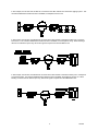
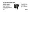
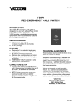
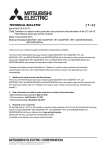
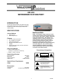
ISSUE 3
VIP-810
NETWORKED STATION PORT
INTRODUCTION
The VIP-810 networked station port allows most loop
start terminal devices to be connected to a managed
IP-based Local area network (LAN) or Wide area
network (WAN).
SPECIFICATIONS
INSTALLATION
Access Methods
•
•
NOTE: The telephone system referred to in this
manual is the customer premise equipment such
as an electronic key system, a PBX or a dedicated
single line telephone sets. The VIP-810 is not
intended for direct or indirect connection to the
public telephone network. When used with a
customer premise telephone system such as a
key system or PBX system, these units are
interfaced to the system via a fully protected loop
start trunk (FXO) port. Also, the host system
must be configured to disallow central office
trunk conferencing in order to prevent indirect
connection to the public network.
PBX, FXO Port
POTS telephone set
Features
•
•
•
•
•
•
RJ-45 for network connection
RJ-11 telephone connection
Front panel activity LED
Network activity LEDs on RJ-45
4 RENS
2.5mm jack for DC power (115VAC TO 24VDC
adapter provided)
Dimensions/Weight
Precautionary Designations
• 1.88" H x 5.50" W x 4.15" D
(4.78cm H x 13.97cm W x 10.54cm D)
• Weight: 0.55 lbs. (0.25 kg)
CAUTION
Nominal Specifications
Input Impedance:
Input Level:
Output Impedance:
Output Level:
RISK OF ELECTRIC SHOCK
600 Ohms
-10dBm
600 Ohms
- 10dBm nominal
DO NOT OPEN
CAUTION: To reduce the risk of electric shock,
Do not remove cover.
No user serviceable parts inside.
Refer servicing to qualified service personnel.
Nominal Power Requirements
Voltage:
Current:
24VDC
325mA
This symbol indicates that dangerous
voltage constituting a risk of electric
shock is present within this unit.
Environment
Temperature:
Humidity:
This symbol indicates that there are
important operating and maintenance
instructions in the literature accompanying
this unit.
0 to +40°C
0 to 85% non-precipitating
1
947052
Mounting
PBX Access
The VIP-810 was designed for wall or table mounting.
Secure unit to wall studs or a suitable brace away
from heat sources or strong magnetic fields (motors,
fans, power supplies, etc.) with the control and
terminal strip accessible. One wood screw is included
for mounting.
When using the VIP-810 with an electronic key
system or PBX, a VIP-810 must be connected to a
loop start trunk (FXO) port.
When using the VIP-810 with a PBX station port, a
VIP-820 must be used to interface the telephone
system with the network.
Power Connections
NOTE: This equipment must be installed near an
AC power outlet due to the power cord being used
as a disconnect device.
•
The VIP-810 is provided with a VP-324 for North
American use.
After all required connections have been made,
plug the VP-324 into appropriate AC wall outlet.
Operation
Press line key (electronic key system) or dial trunk
access code (PBX) to connect to the VIP-810. The
VIP-810 automatically disconnects from page when
you hang up.
Pots Telephone Access
The VIP-810 may be connected to a POTS telephone
set. This gives you direct access to the network.
APPLICATION EXAMPLES
Use the VIP-810 with a PBX Loop Start Trunk Port and a VIP-800 to interface the telephone system to Valcom
powered speakers over a network. When the PBX Loop Start Trunk Port is accessed, the VIP-810 will activate the
VIP-800.
In this example, the VIP-810 is connected to the data network jack already installed and now the network connected
telephone can reach into the existing Valcom Page Control to access one way all call priority paging. This
configuration could be used at a guard shack where network access is available, but telephone access is not.
2
947052
In this example, the VIP-810 and VIP-800 are connected to the data network as a stand alone paging system. This
could be installed where network access is available, but telephone access is not.
In this example, the VIP-810 and VIP-820 are connected to the data network to extend the station port to a remote
Door Phone . This could be installed where network access is available, but not telephone wiring. When initiating a
call from the VIP-820 an open loop, disconnect signal is required from the PBX Station Port.
In this example, the VIP-810 and VIP-820 are connected to the data network to extend the station port to a telephone
at a remote location. This could be installed where network access is available, but telephone wiring is not. When
initiating a call from the VIP-820 an open loop, disconnect signal is required from the PBX Station Port.
3
947052
When requesting assistance, you should include all
available information. It is strongly suggested that
you go to the web site and follow the trouble
resolution procedure at http://voip.valcom.com.
TECHNICAL ASSISTANCE
When trouble is reported, verify power is being
supplied to the unit and there are no broken
connections. Check voltages for proper polarity to the
one-way amplified speakers. Table 1 identifies
symptoms of some possible problems with solutions.
If a spare unit is available, substitute a spare unit for
the suspected defective unit.
Valcom equipment is not field repairable. Valcom,
Inc. maintains service facilities in Roanoke, VA.
Should repairs be necessary, attach a tag to the unit
clearly stating your company name, address, phone
number, contact person and the nature of the
problem. Send the unit to:
Assistance in troubleshooting is available from the
factory. Call (540) 563-2000 and press 1 for Technical
Support or via email at [email protected].
SYMPTOM
1. No output to speakers
2. No music output
A.
B.
A.
B.
Valcom, Inc.
Repair & Return Dept.
5614 Hollins Road
Roanoke, Va. 24019-5056
TABLE 1: TROUBLESHOOTING CHART
PROBABLE CAUSE AND SOLUTION
Check for the presence of audio on the page outputs of the VIP-810 during a
page using a test set. Refer to installation section for connection information.
Check the DC voltage at the output of the VP-324. It should be 20 to 28VDC.
Using a test set, check for music on the music input terminals.
Check that speakers are connected to page outputs.
VALCOM LIMITED WARRANTY
Valcom, Inc. warrants its products to be free from defects in materials and workmanship under conditions of normal
use and service for a period of one year from the date of shipment. The obligation under this warranty shall be
limited to the replacement, repair or refund of any such defective device within the warranty period, provided that:
1.
2.
3.
4.
5.
inspection by Valcom, Inc. indicates the validity of the claim;
the defect is not the result of damage, misuse or negligence after the original shipment;
the product has not been altered in any way or repaired by others and that factory sealed units are unopened (a
service charge plus parts and labor will be applied to units defaced or physically damaged);
freight charges for the return of products to Valcom are prepaid;
all units ‘out of warranty’ are subject to a service charge. The service charge will cover minor repairs (major
repairs will be subject to additional charges for parts and labor).
This warranty is in lieu of and excludes all other warranties, expressed or implied, and in no event shall Valcom, Inc.
be liable for any anticipated profits, consequential damages, loss of time or other losses incurred by the buyer in
connection with the purchase, operation or use of the product.
This warranty specifically excludes damage incurred in shipment. In the event a product is received in damaged
condition, the carrier should be notified immediately. Claims for such damage should be filed with the carrier involved
in accordance with the F.O.B. point.
4
947052