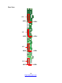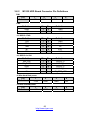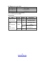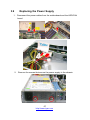
1
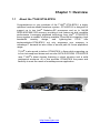
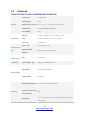
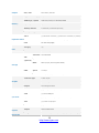
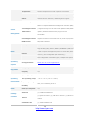
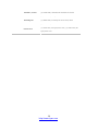
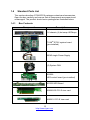
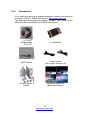
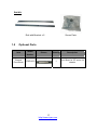
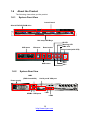
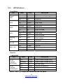
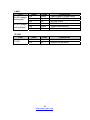
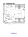
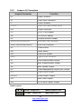
TYAN GT24 B7016 Service Engineer’s Manual 1 http://www.tyan.com 2 http://www.tyan.com PREFACE Copyright This publication, including all photographs, illustrations, and software, is protected under international copyright laws, with all rights reserved. Neither this manual, nor any material contained herein, may be reproduced without written consent of manufacturer. Copyright 2009 MiTAC International Corporation. All rights reserved. ® TYAN is a registered trademark of MiTAC International Corporation. Version 1.01a Disclaimer Information contained in this document is furnished by MiTAC International Corporation and has been reviewed for accuracy and reliability prior to printing. MiTAC assumes no liability whatsoever, and disclaims any ® express or implied warranty, relating to sale and/or use of TYAN products including liability or warranties relating to fitness for a particular purpose or merchantability. MiTAC retains the right to make changes to produce descriptions and/or specifications at any time, without notice. In no event will MiTAC be held liable for any direct or indirect, incidental or consequential damage, loss of use, loss of data or other malady resulting from errors or inaccuracies of information contained in this document. Trademark Recognition All registered and unregistered trademarks and company names contained in this manual are property of their respective owners including, but not limited to the following. TYAN® is a trademark of MiTAC International Corporation. Intel® is a trademark of Intel® Corporation. ® ® AMI , AMIBIOS and combinations thereof are trademarks of AMI Technologies. Microsoft®, Windows® are trademarks of Microsoft Corporation. IBM®, PC®, AT® and PS/2® are trademarks of IBM Corporation. ® Winbond is a trademark of Winbond Electronics Corporation. 3 http://www.tyan.com Federal Communication Commission (FCC) Notice for the USA Compliance Information Statement (Declaration of Conformity Procedure) DoC FCC Part 15: This device complies with part 15 of the FCC Rules Operation is subject to the following conditions: 1) This device may not cause harmful interference; 2) This device must accept any interference received including interference that may cause undesired operation. If this equipment does cause harmful interference to radio or television reception, which can be determined by turning the equipment off and on, the user is encouraged to try one or more of the following measures: – Reorient or relocate the receiving antenna. – Increase the separation between the equipment and the receiver. – Plug the equipment into an outlet on a circuit different from that of the receiver. Consult the dealer on an experienced radio/television technician for help. Notice for Canada This apparatus complies with the Class A limits for radio interference as specified in the Canadian Department of Communications Radio Interference Regulations. (Cet appareil est conforme aux norms de Classe A d’interference radio tel que specifie par le Ministere Canadien des Communications dans les reglements d’ineteference radio.) Notice for Europe (CE Mark) This product is in conformity with the Council Directive 89/336/EEC, 92/31/EEC (EMC). CAUTION: Lithium battery included with this board. Do not puncture, mutilate, or dispose of battery in fire. There will be danger of explosion if battery is incorrectly replaced. Replace only with the same or equivalent type recommended by manufacturer. Dispose of used battery according to manufacturer instructions and in accordance with your local regulatio-ns. 4 http://www.tyan.com About this Manual This manual provides you with instructions on installing your TYAN GT24-B7016. This Manual is intended for experienced users and integrators with hardware knowledge of personal computers. This manual consists of the following parts: Chapter1: Provides an introduction to the TYAN GT24-B7016 barebones, standard parts list, describes the external components, gives a table of key components, and provides block diagram of the system. Chapter2: Covers procedures on installing the CPU, memory modules and hard drives. Chapter3: Covers removal and replacement procedures for pre-installed components. Appendix: List the cable connection and FRU part tables for reference of system setup, and technical support in case a problem arises with your system. For information on the motherboard, please refer to the attached motherboard user’s manual. You can find the detailed description about jumper and BIOS settings from the motherboard manual. 5 http://www.tyan.com SAFETY INFORMATION Before installing and using TYAN GT24-B7016, take note of the following precautions: ·Read all instructions carefully. ·Do not place the unit on an unstable surface, cart, or stand. ·Do not block the slots and opening on the unit, which are provided for ventilation. ·Only use the power source indicated on the marking label. If you are not sure, contact the power company. ·The unit uses a three-wire ground cable, which is equipped with a third pin to ground the unit and prevent electric shock. Do not defeat the purpose of this pin. If you outlet does not support this kind of plug, contact your electrician to replace your obsolete outlet. ·Do not place anything on the power cord. Place the power cord where it will not be in the way of foot traffic. ·Follow all warnings and cautions in this manual and on the unit case. ·Do not push objects in the ventilation slots as they may touch high voltage components and result in shock and damage to the components. ·When replacing parts, ensure that you use parts specified by the manufacturer. ·When service or repairs have been done, perform routine safety checks to verify that the system is operating correctly. ·Avoid using the system near water, in direct sunlight, or near a heating device. ·Cover the unit when not in use. 6 http://www.tyan.com Table of Contents Chapter 1: Overview ......................................................................... 9 1.1 About the TYAN GT24-B7016 .................................................. 9 1.2 Product Models....................................................................... 10 1.3 Features.................................................................................. 11 1.4 Standard Parts List ................................................................. 15 1.4 Standard Parts List ................................................................. 15 1.4.1 Box Contents ................................................................... 15 1.4.2 Accessories ..................................................................... 16 1.5 Optional Parts ......................................................................... 17 1.6 About the Product ................................................................... 18 1.6.1 System Front View........................................................... 18 1.6.2 System Rear View ........................................................... 18 1.6.3 LED Definitions ................................................................ 19 1.6.4 Motherboard (S7016) Layout........................................... 21 1.6.5 Jumpers & Connectors .................................................... 22 1.6.6 System Block Diagram .................................................... 23 1.6.7 Internal View .................................................................... 24 Chapter 2: Setting Up..................................................................... 25 2.0.1 Before you Begin ............................................................. 25 2.0.2 Work Area........................................................................ 25 2.0.3 Tools ................................................................................ 25 2.0.4 Precautions...................................................................... 26 2.1 Installing Motherboard Components....................................... 27 2.1.1 Removing the Chassis Cover .......................................... 27 2.1.2 Installing the CPU and Heatsink...................................... 28 2.1.3 Installing the Memory....................................................... 31 2.1.4 Installing Hard Drives....................................................... 36 2.1.5 Installing the PCI-E Cards ............................................... 38 7 http://www.tyan.com 2.2 Rack Mounting........................................................................ 40 2.2.1 Installing the Server in a Rack......................................... 40 2.2.2 Installing the inner Rails to the Chassis........................... 41 2.2.3 Installing the Outer Rails to the Rack .............................. 42 2.2.4 Rack mounting the Server ............................................... 44 Chapter 3: Replacing Pre-Installed Components ........................ 47 3.1 Introduction ............................................................................. 47 3.2 Disassembly Flowchart........................................................... 47 3.3 Removing the Cover ............................................................... 49 3.4 Replacing Motherboard Components..................................... 49 3.4.1 Replacing Expansion Card .............................................. 49 3.4.2 Disconnecting All Motherboard Cables ........................... 51 3.4.3 Removing the Motherboard ............................................. 52 3.5 Replacing the Slim DVD-ROM.............................................. 53 3.6 Replacing the LED Control Board......................................... 55 3.6.1 M1008 LED Control Board Features ............................... 57 3.6.2 M1008 LED Control Board Connector Pin Definition ...... 57 3.7 Replacing the System Fan.................................................... 58 3.8 Replacing the M1232 HDD Board ........................................ 61 3.8.1 M1232 HDD Board Features ........................................... 63 3.8.2 M1232 HDD Board Connector Pin Definitions ................ 65 Appendix I: Cable Connection Tables .......................................... 69 Appendix II: FRU Parts Table ........................................................ 71 Appendix III: Technical Support.................................................... 73 8 http://www.tyan.com Chapter 1: Overview 1.1 About the TYAN GT24-B7016 ® Congratulations on your purchase of the TYAN GT24-B7016, a highly optimized rack-mountable barebone system. GT24-B7016 is designed to ® support up to two Intel “Nehalem-EP processors and up to 144GB DDR3-800/1066/1333 memory, providing a rich feature set and incredible ® performance. Leveraging advanced technology from Intel , GT24-B7016 server system is capable of offering scalable 32 and 64-bit computing, high bandwidth memory design, and lightning-fast PCI-E bus implementtation.GT24-B7016 not only empowers your company in nowadays IT demand but also offers a smooth path for future application usage. ® TYAN is also proud to deliver GT24-B7016 in flavor while supporting up to four hot-swap hard drives and one slim SATA DVD ROM. GT24-B7016 ® uses TYAN ’s latest chassis featuring a robust structure and a solid mechanical enclosure. All of this provides GT24-B7016 the power and flexibility to meet the needs of nowadays server application. 9 http://www.tyan.com 1.2 Product Models Model B7016G24W4H B7016G24V4H HDD Bays Hot-swap, 4HDDs Hot-swap, 4HDDs 10 http://www.tyan.com Power supply 600W single 600W single 1.3 Features TYAN GT24-B7016 (B7016G24W4H/B7016G24V4H) System Front Panel Form Factor 1U Rackmount Chassis Name GT24 Dimension (D x W x H) 25.4" x 17.2" x 1.72" (645 x 436 x 43.6mm) Motherboard S7016WGM3NR/S7016GM3NR Gross Weight 16 kg Buttons (1) RST / (1) NMI / (1) ID / (1) PWR w/ LED LEDs (1) ID / (1) Warning / (3) LAN / (1) BMC I/O Ports (2) USB ports Type / Q'ty 3.5" Hot-Swap / (4) External Drive Bay Supported HDD SAS 3.0Gb/s / SATA-II 3.0Gb/s Interface System Cooling FAN (5) 4cm fans Type of ODD / Q'ty Slim-type SATA DVD-ROM / (1) Type EPS1U Input Range Full-range AC(100-240V) Frequency 47~63 Hertz Output Watts 600 Watts Efficiency PFC / 80-plus Supported CPU Series Intel Xeon Processor 5500 Series Socket Type / Q'ty LGA1366 / (2) Configuration Peripherals Power Supply Processor Thermal Design Power 95W (TDP) wattage Up to 4.8/ 5.86/ 6.4GT/s with Intel QuickPath Interconnect System Bus (QPI) support 11 http://www.tyan.com Chipset Memory IOH / ICH Intel 5520 / ICH10R Supported DIMM Qty (18) DIMM sockets DIMM Type / Speed DDR3 800/1066/1333 RDIMM/UDIMM Capacity Up to 144GB at launch w/ dual rank RDIMMs Memory channel 6 Channels (3 Channels per CPU) Memory voltage 1.5V PCI-E (1) PCI-E Gen.2 x8 slot / (1) PCI-E Gen.2 x16 slot (w/ x8 link) Expansion Slots Pre-install TYAN Riser M2083-RS, PCI-E x16 1U riser card (left) / M2081-2, PCI-E x8 Card 1U riser card (right) Port Q'ty (3) Controller Intel 82574L / Intel 82576EB LAN Controller LSI SAS1068E Speed 3.0 Gb/s RAID RAID 0/1/1E (LSI Integrated RAID) Controller ICH10R Speed 3.0 Gb/s RAID RAID 0/1/10/5 (Intel Matrix RAID) SAS (optional) Storage SATA Graphic I/O Ports Connector type D-Sub 15-pin Resolution 1600x1200@75Hz Chipset ServerEngines Pilot2 USB (4) ports (2 at front, 2 at rear) COM (1) DB-9 COM port PS/2 (1) PS/2 connector (for Keyboard and Mouse) VGA (1) D-Sub 15-pin port RJ-45 (3) ports Chipset Winbond W83793G Voltage Monitors voltage for CPU, memory, chipset & power supply System Monitoring 12 http://www.tyan.com Temperature Monitors temperature for CPU & system environment LED Fan fail LED indicator / Over temperature warning indicator Others Chassis intrusion detection / Watchdog timer support Onboard Chipset Onboard ServerEngines Pilot2 IPMI 2.0 compliant baseboard management controller (BMC) ServerEngines Pilot2 / Supports storage over IP and remote platform-flash/ BIOS IPMI Feature update / Hardware-based security engine for SSL Server Management acceleration ServerEngines Pilot2 Highest resolution secured KVM over IP / Dual 10/100/1000 iKVM Feature Mb/s MAC interfaces Brand / ROM size AMI / 4MB Plug and Play (PnP) /PCI2.3 /WfM2.0 /SMBIOS2.3 /PXE boot BIOS / ACPI 2.0 power management /Power on mode after power Feature recovery / User-configurable H/W monitoring / Auto-configurable of hard disk types / Multiple boot options Operating OS supported list Please refer to our OS supported list. FCC (DoC) Class A CE (DoC) Yes Operating Temp. 10° C ~ 35° C (50° F~ 95° F) Operating Non-operating Temp. - 40° C ~ 70° C (-40° F ~ 158° F) Environment In/Non-operating System Regulation 90%, non-condensing at 35° C Humidity RoHS RoHS 6/6 Complaint Yes Barebone (1) GT24B7016 Barebone Package Contains (1) Quick Ref. Guide / (1) MB User's manual + (1) BB User's Manual manual Installation CD (1) TYAN installation CD 13 http://www.tyan.com Heatsink / Cooler (2) CHSK-0380, LGA1366 CPU heatsinks for S7016 Rail kit (1) CRAL-0031, sliding rail kit for KGT24 Mounting Ear (1) CEAR-0050, mounting ear kit for GT20/ GT24 Others (1) HDD screw pack (1) CCBL-0310, US type power cord / (1) CCBL-0300, EU Power Cord type power cord 14 http://www.tyan.com 1.4 Standard Parts List This section describes GT24-B7016 package contents and accessories. Open the box carefully and ensure that all components are present and undamaged. The product should arrive packaged as illustrated below. 1.4.1 Box Contents Component Description 1U chassis,(4) hot swap HDDbays ® TYAN S7016 system board (pre-installed) 600W single Power Supply (5) System FAN M1008: LED control board (pre-installed) M1232 HDD Board M2083-RS PCI-E riser card M2081-2 PCI-E riser card 15 http://www.tyan.com 1.4.2 Accessories If any items are missing or appear damaged, contact your retailer or browse to TYAN®’s website for service: http://www.tyan.com ® The web site also provides information of other TYAN products, as well as FAQs, compatibility lists, BIOS settings, etc. ® 1 x TYAN Motherboard Drive CD 2 x Heatsinks HDD Screws Power Cables Left to right: Europe, US Mounting Ears & Screws Barebone Manual & Mainboard Manual 16 http://www.tyan.com Rail Kit Rail with Bracket x 2 1.5 Screw Pack Optional Parts Item Chassis Front-Bezel Model Number CFBZ-0070 Picture Quantity Description 1 Front Bezel for GT series 1U chassis 17 http://www.tyan.com 1.6 About the Product The following views show you the product. 1.6.1 System Front View Control board Slim SATA DVD-ROM drive Hot-swap HDD Bays USB ports ID button Reset button ID LED Warning LED BMC LED Power button(with LED) NMI button 1.6.2 System Rear View LAN3 Power supply (IPMI shared NIC) Serial port & VGA port KB/MS USB ports LAN1 LAN2 18 http://www.tyan.com NIC3 NIC2 NIC1 1.6.3 LED Definitions Front Panel LED Power LED NIC1 NIC2 NIC3 Warning LED ID LED BMC LED State Color Description On Green System is turned on On Off Blinking On off Blinking On off Blinking On off Green Off Green Green off Green Green off Green Green off On Red Off On Off On Blinking Off Off Blue Off Amber Amber Off System is under S1 or S3 state Power off LAN active LAN linked LAN not linked LAN active LAN linked LAN not linked LAN active LAN linked LAN not linked Fan fail /Over temperature /Over voltage No failure System identified System not identified PSU fail PSU alert No failure Rear I/O LAN1/LAN2 LED RJ-45 Linkage/ Activity(left) RJ-45 Linkage/ Activity(Right) State Color Description On Green 10Mb/100Mb/1000Mb linked Blinking Green 10Mb/100Mb/1000Mb activity Off Off No LAN linked On Amber 1000Mb linked/activity On Green 100Mb linked/activity Off Off 10Mb mode or No LAN linked NOTE: “Left” and “Right” are viewed from the rear panel. 19 http://www.tyan.com LAN3 LED RJ-45 Linkage/ Activity(left) RJ-45 Linkage/ Activity(Right) State On Blinking Off On On Off Color Green Green Off Amber Green Off Description 10Mb/100Mb/1000Mb linked 10Mb/100Mb/1000Mb activity No LAN linked 1000Mb linked/activity 100Mb linked/activity 10Mb mode or No LAN linked State On Off Color Blue Off Description System identified System not identified ID LED LED ID LED 20 http://www.tyan.com 1.6.4 Motherboard (S7016) Layout The diagram is representative of the latest board revision available at the time of publishing. The board you receive may not look exactly like the above diagram. 21 http://www.tyan.com 1.6.5 Jumpers & Connectors Jumper/Connector Function J3 IPMB Connector J4 Front Panel Connector J7 PSMI Connector J11/J12 USB Front Panel Header (blue) J16 COM2 Connector J17 CPLD JTAG Header J22 ICH SGPIO Header J27 Chassis Intrusion Header J49/J51/J52/J53/J54/J55 8-pin 4056 Fan Connector J5/J21/J24/J25/J28/J30/J50 4-pin Fan Connector J57 Power Switch J58 Reset Switch J59 LAN3 LED Header USB1 Type-A USB Connector J6 SAS Enable/Disable Jumper J56 BMC Enable/Disable Jumper J60 BMC Update Jumper J61 Flash Manageability Engine (ME) Jumper JP1 Clear CMOS Jumper JP2/JP3 COM2 Switch Jumper JP8 BMC Flash Jumper JP9 PCI-E x8/x16 select Jumper Jumper Legend OPEN - Jumper OFF Without jumper cover CLOSED - Jumper ON With jumper cover 22 http://www.tyan.com 1.6.6 System Block Diagram 23 http://www.tyan.com 1.6.7 Internal View 5 4 3 2 1 1 2 3 4 5 HDD Cage M1232 HDD Board System Fan Unit Power Supply PCI-E Riser Card Assembly 24 http://www.tyan.com Chapter 2: Setting Up 2.0.1 Before you Begin This chapter explains how to install the CPUs, CPU heatsinks, memory modules, and hard drives. Instructions on inserting add on cards are also given. 2.0.2 Work Area Make sure you have a stable, clean working environment. Dust and dirt can get into components and cause malfunctions. Use containers to keep small components separated. Putting all small components in separate containers prevents them from becoming lost. Adequate lighting and proper tools can prevent you from accidentally damaging the internal components. 2.0.3 Tools The following procedures require only a few tools, including the following: A cross head (Phillips) screwdriver A grounding strap or an anti-static pad Most of the electrical and mechanical connections can be disconnected with your hands. It is recommended that you do not use pliers to remove connectors as it may damage the soft metal or plastic parts of the connectors. 25 http://www.tyan.com 2.0.4 Precautions Components and electronic circuit boards can be damaged by discharges of static electricity. Working on a system that is connected to a power supply can be extremely dangerous. Follow the guidelines below to avoid damage to GT24-B7016 or injury to yourself. Ground yourself properly before removing the top cover of the system. Unplug the power from the power supply and then touch a safely grounded object to release static charge (i.e. power supply case). If available, wear a grounded wrist strap. Alternatively, discharge any static electricity by touching the bare metal chassis of the unit case, or the bare metal body of any other grounded appliance. Avoid touching motherboard components, IC chips, connectors, memory modules, and leads. The motherboard is pre-installed in the system. When removing the motherboard, always place it on a grounded anti-static surface until you are ready to reinstall it. Hold electronic circuit boards by the edges only. Do not touch the components on the board unless it is necessary to do so. Do not flex or stress circuit boards. Leave all components inside the static-proof packaging that they ship with until they are ready for installation. After replacing optional devices, make sure all screws, springs, or other small parts are in place and are not left loose inside the case. Metallic parts or metal flakes can cause electrical shorts. Note: All connectors are keyed to only attach one way. All use the correct screw size as indicated in the procedures. 26 http://www.tyan.com 2.1 Installing Motherboard Components This section describes how to install components on to the motherboa-rd, including CPUs, memory modules and add on cards. 2.1.1 Removing the Chassis Cover Follow these instructions to remove GT24-B7016 chassis cover. 1. Unscrew the rear top cover on the back side as shown in the small diagram. 2. Slide the rear top cover out. 27 http://www.tyan.com 2.1.2 Installing the CPU and Heatsink Follow the steps below on installing CPUs and CPU heatsinks. 1. Locate the CPU socket. 2. Press the lever and unlock the CPU socket. 28 http://www.tyan.com A 3. Lift the CPU protection cap up and lay the CPU into the socket(A), ensuring pin1 is correctly located(B); B 4. Close the socket cover and press the CPU lever down to secure the CPU; 29 http://www.tyan.com 5. Place the heatsink on top of the CPU and secure it with 8 screws. Note: The system supports two CPUs. For CPU sequence please refer to Chapter 1.6.4. 30 http://www.tyan.com 2.1.3 Installing the Memory Follow these instructions to install the memory modules onto the motherboard. 1. Locate the memory slots on the motherboard. 2. Press the memory slot locking levers in the direction of the arrows as shown in the following illustration. 3. Align the memory module with the slot. When inserted properly, the memory slot locking levers lock automatically onto the indentations at the ends of the module. 31 http://www.tyan.com Note: 1). For the DIMM number please refer to the motherboard placement in “2.3 - Board Parts, Jumpers and Connectors” for memory installation. 2). Refer to the memory population option table for recommended memory installation instruction. Memory Population Option Table The following pictures show common types of DDR3 memory modules. 32 http://www.tyan.com CPU0 CPU1 Channel D DIMM D0, D1 & D2 Channel A DIMM A0, A1 & A2 Channel E DIMM E0, E1 & E2 Channel B DIMM B0, B1 & B2 Channel F DIMM F0, F1 & F2 Channel C DIMM C0, C1 & C2 33 http://www.tyan.com The following table outlines the suggested rules for populating memory. For 3 slots per channel RDIMM DIMM2 DIMM1 Single Rank x x x x x x Dual Rank x x x x x x Quad Rank UDIMM x DIMM2 x x DIMM1 DIMM0 Single Rank x x Dual Rank x x x DIMM with heat spreader DIMM0 DIMM2 DIMM1 x DIMM0 x x x x x x 34 http://www.tyan.com Note: 1). “X” indicates a populated DIMM slot. 2). If installing only one processor, you can choose either CPU0 or CPU1. 3). For two slots per channel configuration, it requires population to start with the DIMM slots furthest away from the processor. 35 http://www.tyan.com 2.1.4 Installing Hard Drives The GT24-B7016 supports four 3.5” hard drives. Follow these instructions to install a hard drive. 4. 1. Press the locking lever latch and pull the locking lever open. 2. Slide the HDD tray out. 3. Remove the 6 screws. Place a hard drive into the drive tray. 36 http://www.tyan.com 5. Use 6 HDD screws to secure the HDD. 6. Reinsert the HDD tray into the chassis and press the locking lever to secure the tray. 37 http://www.tyan.com 2.1.5 Installing the PCI-E Cards The GT24-B7016 supports two PCI-E expansion slots. Follow these instructions to install PCI-E cards. 1. Pull open the tab of PCI-E slot on the rear panel in the direction as shown to release the PCI bracket. 2. Take off the PCI bracket. 3. Insert the PCI-E card in the direction of arrow as shown. Close the tab of PCI-E slot to secure PCI-E card. 4. Repeat the same procedures to insert the second PCI-E card into the expansion slot. 38 http://www.tyan.com 1 2 3 4 5. The installation of two PCI-E expansion cards are now complete. 39 http://www.tyan.com 2.2 Rack Mounting After installing the necessary components, the TYAN GT24-B7016 can be mounted in a rack using the supplied rack mounting kit. Rack mounting kit Sliding Rails x 2 Sliding Brackets x 4 (Front x 2, Rear x 2) Mounting Ears (including screws) x 2 Screws Kit x 1 Mounting Brackets x 4 2.2.1 Installing the Server in a Rack Follow these instructions to mount the TYAN GT24-B7016 into an industry standard 19" rack. NOTE: Before mounting the TYAN GT24-B7016 in a rack, ensure that all internal components have been installed and that the unit has been fully tested. Screws List No. Size Quantity A Screw M4-4L 18 B M5-8L 10 C M5-15 4 40 http://www.tyan.com 2.2.2 Installing the inner Rails to the Chassis 1. Screw the mounting ear to each side of TYAN GT24-B7016 as shown using 2 screws from the supplied screws kit. 2. Draw out the inner rails from rail assembly. Install inner rails to left and right sides of chassis using 1 M4-4L(A) screw for each side. 41 http://www.tyan.com 2.2.3 Installing the Outer Rails to the Rack 1. Measure the distance between inner side of the front and rear mounting brackets in the rack. 2. Locate the front and rear brackets. Rear Bra cket x 2 Front Brack et x2 3. Secure the front bracket to outer rail with 2 M4-4L(A) screws. 4. Reserve the distance same as in Step 2 on rear bracket. Secure the rear bracket to outer rail with 2 M4-4L(A) screws. 5. Secure the outer rail to the rack using 2 brackets and 4 M5-8L(B) screws for each side. Secure the mounting brackets from inside, not outside, of the rack. 42 http://www.tyan.com Mounting Bra cket 43 http://www.tyan.com 2.2.4 Rack mounting the Server 3. Draw out the middle rail to the latch position. 4. Lift the chassis and then insert the inner slide rails into the middle rails. 5. Push the chassis in and press the latch key (A). Then push the whole system into the rack (B) A 6. B Secure the mounting ears of chassis to the rack with 2 M5-15L(C) screws. 44 http://www.tyan.com Note: To avoid injury, it is strongly recommended that two people lift the TYAN GT24-B7016 into the place while a third person screws it to the rack. 45 http://www.tyan.com NOTE 46 http://www.tyan.com Chapter 3: Replacing Pre-Installed Components 3.1 Introduction This chapter explains how to replace the pre-installed components, including the Motherboard, M1008 LED control board, M1232 HDD board, M2083-RS/M2081-2 PCI-E Riser card, System fan, ODD drive, Power supply unit etc. 3.2 Disassembly Flowchart The following flowchart outlines the disassembly procedure. Rear Components Chassis rear cover DIMMs Power M2083-RS PCI-E Riser card M2081-2 PCI-E Riser card CPU/Heatsink Assembly PCI Card Mainboard Mainboard 47 http://www.tyan.com Front Components Chassis rear cover DVD ROM PCBs M1008 LED Control Board M1232 HDD Board 48 http://www.tyan.com FAN 3.3 Removing the Cover Before replacing any parts you must remove the chassis cover. Follow Chapter 2.1.1 to remove the cover of the GT24-B7016. 3.4 Replacing Motherboard Components Follow these instructions to replace motherboard components, including the motherboard. 3.4.1 Replacing Expansion Card The GT24-B7016 has one preinstalled PCI-E×16 riser card, Follow the instructions below to disassemble the M2083-RS PCI-E riser card. 1. Locate the riser card on the motherboard, unscrew the bracket from the slot. 2. Unscrew the bracket and pull it up from the slot in the direction as shown. 49 http://www.tyan.com 3. Unscrew the cards from the bracket. a. remove Card M2083 b. remove Card M2081-2 4. Install a new riser card onto the bracket following the procedures mentioned earlier in reverse order. 50 http://www.tyan.com 3.4.2 Disconnecting All Motherboard Cables Before replacing the motherboard or certain components, remove cables connected to the motherboard. Follow these instructions to remove all motherboard cables. 1. Disconnect all the power cable. 2. Disconnect SATA DVD cable, Mini SAS cable, USB cable and front panel cable. 3. Disconnect fan cables. 51 http://www.tyan.com 3.4.3 Removing the Motherboard After removing all of the aforementioned cables, follow the instructions below to remove the motherboard from the chassis. 1. Remove the heatsinks and processors if installed. 2. Remove the nine screws securing the motherboard to the chassis. 3. Carefully lift the motherboard from the chassis. 52 http://www.tyan.com 3.5 Replacing the Slim DVD-ROM Follow these instructions to replace the M1008 LED control board. 1. Remove the power and data cables from the slim DVD-ROM adapter. 2. Press the tab in the directions as shown to release the DVD-ROM drive. 3. The DVD-ROM drive will be freed from the drive bay after pressing the tab. 4. Disconnect the power and data cables from the DVD-ROM drive. 53 http://www.tyan.com 5. Remove two screws that secure DVD-ROM drive to the bracket. 6. 7. Replace the DVD-ROM drive. Secure DVD-ROM to the bracket using two screws. Then replace the unit into the drive bay and connect the DVD-ROM power and data cables. 54 http://www.tyan.com 3.6 Replacing the LED Control Board Follow these instructions to replace the M1008 LED control board. 1. Remove the two screws securing the LED control board unit to the chassis. 2. Push the LED control board unit out and unplug the cables from the connectors at the back of the unit. 3. Remove three screws securing the LED control board to the bracket. 55 http://www.tyan.com 4. Lift the LED control board free from the chassis. After replacing the LED control board, insert the unit into the chassis following the above procedures in reverse. 56 http://www.tyan.com 3.6.1 M1008 LED Control Board Features J1 3.6.2 J3 M1008 LED Control Board Connector Pin Definition J1: USB Header Definition VCC USB1USB1+ GND Key Pin 1 3 5 7 9 Pin 2 4 6 8 10 Definition VCC USB2USB2+ GND GND Pin 1 3 5 7 9 11 13 15 17 19 21 23 Pin 2 4 6 8 10 12 14 16 18 20 22 24 Definition J3: SSI Definition PW_LED+ KEY PW_LEDHD/LAN3 LED+ HD/LAN3 LEDPWR_SW+ PWR_SWRESET+ RESETID_SW+ TEMP_SENSER EXT_INT 57 http://www.tyan.com VCC ID_LED+ ID_LEDSYS_FAULT1SYS_FAULT2LAN1_LED+ LAN1_LEDICH_SMBDAT ICH_SMBCLK INTRU# LAN2_LED+ LAN2_LED- 3.7 Replacing the System Fan Follow these instructions to replace the cooling fans in your system. 1. 2. Locate the cooling fans in your system. Unplug the cables connected to the mainboard and lift the fan unit up from the chassis. 3. Follow Step A and B to unlock the fans. After replacing the new fans, reinstall the fans into the chassis following Step A and B in reverse order. 58 http://www.tyan.com A B C 1. Push the fan unit away from the case. 2. After replacing the new fan unit, push the new fan back into the case. D 59 http://www.tyan.com E 4. Connect the fan cables. 60 http://www.tyan.com 3.8 Replacing the M1232 HDD Board Step 1: Disconnect all cables connected to M1232 HDD Board. Power cable: SATA Power cable and Mini SAS cable: Step 2: Remove the three screws securing the bracket to the chassis base. 61 http://www.tyan.com Step 3: Lift the bracket up from the chassis. Step 4: Unscrew M1232 board from the bracket. Step 5: Replace a new M1232 HDD Board and reinstall it into the chassis following the above steps in reverse. 62 http://www.tyan.com 3.8.1 M1232 HDD Board Features Front View J5 PW2 PW1 J40 J18 J15 J39: Mini SAS Connector J41 J7 63 http://www.tyan.com Rear View: J10 LED1 LED2 J11 LED3 LED4 J13 LED5 LED6 J14 LED7 LED8 64 http://www.tyan.com 3.8.2 M1232 HDD Board Connector Pin Definitions PW1 Pin Definition 1 +12V 2 GND 3 GND 4 +5V PW2 Definition GND +12V Pin 1 3 Pin 2 4 Definition GND +12V Pin 1 3 5 7 9 Pin 2 4 6 8 10 Definition GND 3.3V NI KEY GND Pin 1 3 5 7 9 Pin 2 4 6 8 10 Definition SGPIO_0 SGPIO_1 SGPIO_2 SGPIO_3 HD_ERR_LED J15 SGPIO JTAG Definition TCK TDO TMS NI TDI J41 SGPIO for IOH Definition SM_CLK SM_DATA GND KEY NI J5 Slim Hard Disk power Pin Definition 1 +12V 2 GND 3 GND 4 +5V 2 GND 3 GND 4 +5V J18 Slim CDROM power Pin Definition 1 +12V 65 http://www.tyan.com J40 PWM select for system FAN3 Pin Definition 1 CPU_PWM 2 PWM_12(FAN3) 3 CPU_PWM2 Pin 1-2 chose by CPU_PWM (Default) Pin 2-3 chose by CPU_PWM2 LED Definition: LED Color State Description HDD fail LED Amber On SATA/SAS HDD fail Off No failure found (LED 2/4/6/8) Power/Access LED (LED 1/3/5/7) SATA/SAS HDD On HDD Green Blinking ready SATA/SAS HDD access activity Off 66 http://www.tyan.com Power disconnected 3.9 Replacing the Power Supply 1. Disconnect the power cables from the motherboard and the HDD/FAN board. 2. Remove the screws that secure the power supply to the chassis. 67 http://www.tyan.com 3. Take out the power unit and install a new one follow the above steps in reverse. 68 http://www.tyan.com Appendix I: Cable Connection Tables System Fan to S7016 MB System Fan Connect to S7016 MB Fan1 → → → → → J54 Fan2 Fan3 Fan4 Fan5 J53 J52 J51 J49 M1232 HDD Board to S7016 MB Cable M1232 Connect to S7016 MB Mini-SAS Cable J39 → J13 M1008 LED Control Board to S7016 MB Cable M1008 Connect to S7016 MB Control Cable J3 J4 USB Cable J1 → → J11 Power Supply Cables PSU to S7016 MB PSU Connect to S7016 MB 2X12 PWR → → → PW1 P2 P8 69 http://www.tyan.com PW2 PW3 PSU to M1232 PSU Connect to M1232 P3 → PW2 P4 → PW1 DVD-ROM to S7016 MB & M1232 Cable Connect to S7016 & M1232 SATA Cable → S7016 MB J26 Slim DVD SATA PWR Cable → M1232 J18 70 http://www.tyan.com Appendix II: FRU Parts Table GT24-B7016 FRU Parts Item Model Number Part Number Picture Quantity Description Power Supply CPSU-0262 471015200217 1 600W single Power Supply FAN CFAN-0241 336252012294 5 14700RPM,40*40*28MM Heatsink & Cooler CHSK-0380 34378090001 1 GT24-B7016 Heatsink M2081-2 / 1 Riser Card M2083-RS / 1 PCI-E X16 1U Riser Card CRAL-0031 452783400001 1 Slide Rail Kit CEAR-0050 340740900010 1 CCBL-067O 422784300005 1 Mini SAS Cable, 400mm CCBL-0310 332810000280 1 A/C Power Cord, L=1830mm,US type CCBL-0300 332810000281 1 A/C Power Cord, L=1830mm,EU type PCBA Rack Mounting Parts Cable Set 71 http://www.tyan.com Mounting Ear Kit NOTE 72 http://www.tyan.com Appendix III: Technical Support If a problem arises with your system, you should first turn to your dealer for direct support. Your system has most likely been configured or designed by them and they should have the best idea of what hardware and software your system contains. Hence, they should be of the most assistance for you. Furthermore, if you purchased your system from a dealer near you, take the system to them directly to have it serviced instead of attempting to do so yourself (which can have expensive consequence). If these options are not available for you then MiTAC International Corporation can help. Besides designing innovative and quality products for over a decade, MiTAC has continuously offered customers service beyond their expectations. TYAN’s website (http://www.tyan.com) provides easy-to-access resources such as in-depth Linux Online Support sections with downloadable Linux drivers and comprehensive compatibility reports for chassis, memory and much more. With all these convenient resources just a few keystrokes away, users can easily find their latest software and operating system components to keep their systems running as powerful and productive as possible. MiTAC also ranks high for its commitment to fast and friendly customer support through email. By offering plenty of options for users, MiTAC serves multiple market segments with the industry’s most competitive services to support them. Please feel free to contact us directly for this service at [email protected] Help Resources: 1. See the beep codes section of this manual. 2. See the TYAN’s website for FAQ’s, bulletins, driver updates, and other information: http://www.tyan.com 3. Contact your dealer for help before calling TYAN. 4. Check the TYAN user group: alt.comp.periphs.mainboard.TYAN 73 http://www.tyan.com Returning Merchandise for Service During the warranty period, contact your distributor or system vendor FIRST for any product problems. This warranty only covers normal customer use and does not cover damages incurred during shipping or failure due to the alteration, misuse, abuse, or improper maintenance of products. Note: A receipt or copy of your invoice marked with the date of purchase is required before any warranty service can be rendered. You may obtain service by calling the manufa-cturer for a Return Merchandise Authorization (RMA) nu-mber. The RMA number should be prominently displayed on the outside of the shipping carton and the package should be mailed prepaid. TYAN will pay to have the board shipped back to you. ® TYAN GT24-B7016 Service Engineer’s Manual V1.01a Document No.: D2005-100 74 http://www.tyan.com