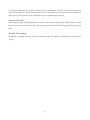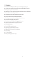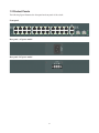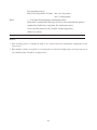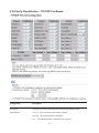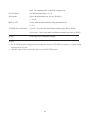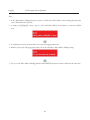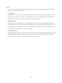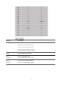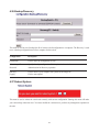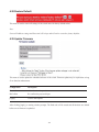
1
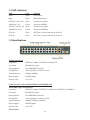
KFS-2621 Web Smart 24-Port 10/100 Fast Ethernet Switch with 2 Gigabit Combo Ports , User s Manual DOC.091229 -1- (C) 2009 KTI Networks Inc. All rights reserved. No part of this documentation may be reproduced in any form or by any means or used to make any directive work (such as translation or transformation) without permission from KTI Networks Inc. KTI Networks Inc. reserves the right to revise this documentation and to make changes in content from time to time without obligation on the part of KTI Networks Inc. to provide notification of such revision or change. For more information, contact: United States KTI Networks Inc. P.O. BOX 631008 Houston, Texas 77263-1008 Phone: Fax: E-mail: URL: International 713-2663891 713-2663893 [email protected] http://www.ktinet.com/ Fax: 886-2-26983873 E-mail: [email protected] URL: http://www.ktinet.com.tw/ -2- The information contained in this document is subject to change without prior notice. Copyright (C) All Rights Reserved. TRADEMARKS Ethernet is a registered trademark of Xerox Corp. FCC NOTICE This device complies with Part 15 of the FCC Rules. Operation is subject to the following two conditions: (1) This device may not cause harmful interference, and (2) This device must accept any interference received, including the interference that may cause undesired operation. CE NOTICE Marking by the symbol indicates compliance of this equipment to the EMC directive of the European Community. Such marking is indicative that this equipment meets or exceeds the following technical standards: EMC Class A EN55022:2006 EN61000-3-2:2006 EN61000-3-3:1995/A1:2001/A2:2005 Class A EN 55024:1998/A1:2001/A2:2003 IEC 61000-4-2:2001 IEC 61000-4-3:2002/A1:2002 IEC 61000-4-4:2004 IEC 61000-4-5:2001 IEC 61000-4-6:2003 IEC 61000-4-8:2001 IEC 61000-4-11:2001 -3- Table of Contents 1. Introduction................................................................................................................................... 6 1.1 Features ................................................................................................................ 8 1.2 Product Panels...................................................................................................... 9 1.3 LED Indicators .................................................................................................... 10 1.4 Specifications ...................................................................................................... 10 2. Installation................................................................................................................................... 13 2.1 Unpacking ........................................................................................................... 13 2.2 Safety Cautions................................................................................................... 13 2.3 Mounting the Switch............................................................................................ 14 2.4 AC Power Supply ................................................................................................ 16 2.5 DC Power Supply................................................................................................ 16 2.6 Reset Button ....................................................................................................... 17 3. Making Connections and Configuring IP Address .................................................................18 3.1 Making UTP Connections ................................................................................... 18 3.2 Making Fiber Connection .................................................................................... 19 3.3 LED Indication..................................................................................................... 21 3.4 Configuring IP Address and Password for the Switch......................................... 22 4. Web Management ....................................................................................................................... 23 4.1 Abbreviation ........................................................................................................ 23 4.2 Web Interface...................................................................................................... 24 4.3 Start Browser Software and Making Connection ................................................ 24 4.4 Login to the Switch Unit ...................................................................................... 24 4.5 Main Management Menu .................................................................................... 25 4.6 System Configuration.......................................................................................... 27 4.7 Port Configuration ............................................................................................... 29 4.8 Port Mirroring ...................................................................................................... 31 4.9 Bandwidth Control............................................................................................... 32 4.10 Broadcast Storm Control................................................................................... 34 4.11 VLAN Mode....................................................................................................... 35 -4- 4.12 VLAN Member (Port-based) ............................................................................. 37 4.13 VLAN Member (Tag-based) .............................................................................. 39 4.14 Multi to 1 VLAN Setting ..................................................................................... 42 4.15 Important Notes for VLAN Configuration........................................................... 43 4.16 QoS Priority Mode............................................................................................. 44 4.17 Priority Classification - Port, 802.1p, IP/DS Based ........................................... 45 4.18 Priority Classification – TCP/UDP Port Based .................................................. 47 4.19 MAC Address Binding ....................................................................................... 49 4.20 TCP/UDP Filter ................................................................................................. 51 4.21 STP Bridge Settings.......................................................................................... 53 4.22 STP Port Settings.............................................................................................. 54 4.23 Link Aggregation ............................................................................................... 57 4.24 Miscellaneous Settings ..................................................................................... 59 4.25 Port Counter...................................................................................................... 61 4.26 Backup/Recovery .............................................................................................. 63 4.27 Reboot System ................................................................................................. 63 4.28 Restore Default ................................................................................................. 64 4.29 Update Firmware .............................................................................................. 64 4.30 Logout ............................................................................................................... 66 Appendix. Factory Default Settings.............................................................................................. 67 -5- 1. Introduction The KFS-2621 is a managed Fast Ethernet switch which is featured with the following switched ports and advantages in a 19” rack mountable box: 24 10/100Mbps Fast Ethernet copper ports 2 combo ports - 10/100/1000Mbps copper & 1000Base-X SFP Model Definition Model Description Management Power Input KFS-2621-S AC power model Managed AC 100 ~ 240V KFS-2621-D DC power model Managed DC 36 ~ 72V Plug and Play The switch is shipped with factory default configuration which behaves like an unmanaged Fast Ethernet switch for workgroup. It provides 24 10/100Mbps copper ports for connections to Ethernet and Fast Ethernet devices. With the featured auto-negotiation function, the switch can detect and configure the connection speed and duplex automatically. The switch also provides auto MDI/MDI-X function, which can detect the connected cable and switch the transmission wire pair and receiving pair automatically. This auto-crossover function can simplify the type of network cables used. Gigabit Ethernet Connectivity Two Gigabit combo ports are provided in the switch. The combo port provides one 10/100/1000Mbps RJ-45 for connecting to Gigabit copper device and one 1000M SFP slot, which can be installed with optional SFP optical fiber transceivers to support one Gigabit 1000Base-X fiber connections respectively when needed. Fiber Connectivity The 1000M SFP slot provided in a combo port, which can be installed with optional SFP optical fiber transceivers to support one Gigabit 1000Base-X fiber connection when needed. Management The switch is embedded with an Http server which provides management functions for advanced network functions including Port Control, Quality of Service, and Virtual LAN functions. The management can be performed via Web browser based interface over TCP/IP network. Quality of Service -6- For advanced application, the switch is featured with powerful Quality of Service (QoS) function which can classify the priority for received network frames based on the ingress port and frame contents. Furthermore, many service priority policies can be configured for egress operation in per-port basis. Virtual LAN (VLAN) For increasing Tagged VLAN applications, the switch is also featured with powerful VLAN function to fulfill the up-to-date VLAN requirements. The switch supports both port-based VLAN and tagged VLAN in per-port basis. AC & DC Power Options In addition to standard AC power input, the switches provide DC options for applications with DC power system. -7- 1.1 Features z Provide 24 10/100Mbps Fast Ethernet ports & 2 Gigabit combo ports z All copper ports support auto-negotiation and auto-MDI/MDI-X detection z Wire speed reception and transmission z Supports 802.3x flow control for full-duplex and backpressure for half-duplex z Store-and-Forward switching method z Self learning for active MAC addresses up to 4K entries z Provide in-band web-based management interface z Provide port status, statistic monitoring and control function z Provide port bandwidth control function z Provide static and LACP port link aggregation function z Support port-based and 802.1Q Tag-based VLAN z Provide QoS function z Provide IGMP snooping function z Support 802.1w RSTP and 802.1D STP z Support DHCP for dynamic IP configuration z No fan design z 19” rack mountable z Wide operating temperature range -8- 1.2 Product Panels The following figure illustrates the front panel and rear panel of the switch: Front panel Rear panel –AC power model Rear panel –DC power model -9- 1.3 LED Indicators LED Color Function Power Green Power status Mngt Green Management status LINK/Act. ( Port 1-24) Green Link & activity status 100M (Port 1-24) Yellow Port speed 100Mbps LINK/Act. (Port 25-26) Green Link & activity status 1000M (Port 25-26) Yellow Port speed 1000Mbps F25 Link Green SFP Fiber is selected and link up on Port 25 F26 Link Green SFP Fiber is selected and link up on Port 26 1.4 Specifications 10/100 Copper Ports Compliance IEEE 802.3 10Base-T, IEEE 802.3u 100Base-TX Connectors Shielded RJ-45 jacks Pin assignments Auto MDI/MDI-X detection Configuration Auto-negotiation or software control Transmission rate 10Mbps, 100Mbps Duplex support Full/Half duplex Network cable Cat.5 UTP Combo Port 25 26 with 10/100/1000 RJ-45 and 1000Mbps SFP 10/100/1000 Copper Port Interface Compliance IEEE 802.3 10Base-T, IEEE 802.3u 100Base-TX, IEEE 802.3u 1000Base-T Connectors Shielded RJ-45 jacks Pin assignments Auto MDI/MDI-X detection Configuration Auto-negotiation or software control Transmission rate 10Mbps, 100Mbps, 1000Mbps Duplex support Full/Half duplex Network cable Cat.5 UTP Fiber interface -10- Compliance IEEE 802.3z 1000Base-SX/LX (mini-GBIC) Connectors SFP for optional SFP type fiber transceivers Configuration Auto/Forced, 1000Mbps, Full duplex Transmission rate 1000Mbps Network cables MMF 50/125 60/125, SMF 9/125 Eye safety IEC 825 compliant Switch Functions MAC Addresses Table 4K entries Forwarding & filtering Non-blocking, full wire speed Switching technology Store and forward Maximum packet length 1536 bytes Flow control IEEE 802.3x pause frame base for full duplex operation Back pressure for half duplex operation VLAN function Port-based VLAN and IEEE 802.1Q Tag-based VLAN QoS function Port-based, 802.1p-based, IP/DS-based Port control Port configuration control via software management Storm control Broadcast storm protection control via software management Aggregation Link aggregation (or called port trunking) Port Mirroring Mirror received frames to a sniffer port IGMP Snooping IGMP snooping configuration Software Management Functions Interfaces Web browser Management objects System settings, port status/statistics, port control, VLAN, QoS, Link aggregation, port mirroring, Firmware upgrade STP/RSTP, Configuration backup and restore AC Power Input Interfaces IEC320 receptacle Operating Input Voltages 100 ~ 240VAC Power Consumption 20W max. @110VAC DC Power Input Interfaces Screw-type terminal block Operating Input Voltages +36 ~ +72VDC Power Consumption 20W max. @48VDC -11- Mechanical Dimension (base) 295 x 160 x 43 mm (WxDxH) Housing Enclosed metal Mounting Desktop mounting, 19” rack mounting Environmental Operating Temperature Typical -20oC ~ +60oC Storage Temperature -30oC ~ +85oC Relative Humidity 10% ~ 90% non-condensing Electrical Approvals FCC Part 15 rule Class A CE EMC, CISPR22 Class A Safety LVD, IEC60950-1 -12- 2. Installation 2.1 Unpacking The product package contains: The switch unit z One AC power cord (Models with AC power) z One 19” rack mounting kit z One product CD-ROM 2.2 Safety Cautions To reduce the risk of bodily injury, electrical shock, fire and damage to the product, observe the following precautions. z Do not service any product except as explained in your system documentation. z Opening or removing covers may expose you to electrical shock. z Only a trained service technician should service components inside these compartments. z If any of the following conditions occur, unplug the product from the electrical outlet and replace the part or contact your trained service provider: - The power cable, extension cable, or plug is damaged. - An object has fallen into the product. - The product has been exposed to water. - The product has been dropped or damaged. - The product does not operate correctly when you follow the operating instructions. z Do not push any objects into the openings of your system. Doing so can cause fire or electric shock by shorting out interior components. z Operate the product only from the type of external power source indicated on the electrical ratings label. If you are not sure of the type of power source required, consult your service provider or local power company. -13- 2.3 Mounting the Switch Desktop Mounting The switch can be mounted on a desktop or shelf. Make sure that there is proper heat dissipation from and adequate ventilation around the device. Do not place heavy objects on the device. Rack Mounting Two 19-inch rack mounting brackets are supplied with the switch for 19-inch rack mounting. The steps to mount the switch onto a 19-inch rack are: 1. Turn the power to the switch off. 2. Install two brackets with supplied screws onto the switch as shown in above figure. 2. Mount the switch onto 19-inch rack with rack screws securely. -14- 3. Turn the power to the switch on. -15- 2.4 AC Power Supply If the purchased switch is with AC power input, one AC power cord which meets the specification of your country of origin was supplied in package. Before installing AC power cord to the switch, make sure the AC power is OFF and the AC power to the power cord is turned off. AC power input specifications Connector: IEC320 type Power Rating: 100 ~ 240VAC, 50/60Hz Voltage Range: 90 ~ 264VAC Frequency: 47 ~ 63 Hz Power Consumption: 20W max. 2.5 DC Power Supply If the purchased switch is with DC power input, the power connector is shown below: DC power input specifications Receptacle: Screw-type terminal block Operating Voltages: +36 ~ +72VDC Power Consumption: 20W max.@48VDC -16- 2.6 Reset Button The reset button is used to perform a reset to the switch. It is not used in normal cases and can be used for diagnostic purpose. If any network hanging problem is suspected, it is useful to push the button to reset the switch without turning off the power. Check whether the network is recovered. The button can also be used to restore the software configuration settings to factory default values. The operations are: Operation Function Press the button more than ˇ seconds when power up Restore factory default settings Press the button and release during switch operation Reboot the switch -17- 3. Making Connections and Configuring IP Address 3.1 Making UTP Connections The 10/100 and 10/100/1000 RJ-45 copper ports support the following connection types and distances: Network Cables 10BASE-T: 2-pair UTP Cat. 3, 4, 5, EIA/TIA-568B 100-ohm 100BASE-TX: 2-pair UTP Cat. 5, EIA/TIA-568B 100-ohm 1000BASE-T: 4-pair UTP Cat. 5 or higher (Cat.5e is recommended), EIA/TIA-568B 100-ohm Link distance: Up to 100 meters Auto MDI/MDI-X Function This function allows the port to auto-detect the twisted-pair signals and adapts itself to form a valid MDI to MDI-X connection with the remote connected device automatically. No matter a straight through cable or crossover cable are connected, the ports can sense the receiving pair automatically and configure themselves to match the rule for MDI to MDI-X connection. It simplifies the cable installation. Auto-negotiation Function The ports are featured with auto-negotiation function and full capability to support connection to any Ethernet devices. The port performs a negotiation process for the speed and duplex configuration with the connected device automatically when each time a link is being established. If the connected device is also auto-negotiation capable, both devices will come out the best configuration after negotiation process. If the connected device is incapable in auto-negotiation, the switch will sense the speed and use half duplex for the connection. Port Configuration Management For making proper connection to an auto-negotiation INCAPABLE device, it is suggested to use port control function via software management to set forced mode and specify speed and duplex mode which match the configuration used by the connected device. -18- 3.2 Making Fiber Connection The SFP slot must be installed with an SFP fiber transceiver for making fiber connection. Your switch may come with some SFP transceivers pre-installed when it is shipped. Installing SFP Fiber Transceiver To install an SFP fiber transceiver into SFP slot, the steps are: 1. Turn off the power to the switch. 2. Insert the SFP fiber transceiver into the SFP slot. Normally, a bail is provided for every SFP transceiver. Hold the bail and make insertion. 3. Until the SFP transceiver is seated securely in the slot, place the bail in lock position. -19- Connecting Fiber Cables LC connectors are commonly equipped on most SFP transceiver modules. Identify TX and RX connector before making cable connection. The following figure illustrates a connection example between two fiber ports: Make sure the Rx-to-Tx connection rule is followed on the both ends of the fiber cable. Network Cables Multimode (MMF) - 50/125Pm, 62.5/125Pm Single mode (SMF) - 9/125Pm Fiber Port Configuration For 1000M fiber application on Port 25 and Port 26, just leave the default port configuration Auto for fiber connection. -20- 3.3 LED Indication 10/100 Copper Port LEDs Combo Ports LEDs LED Function State Interpretation Power Power status ON The power is supplied to the switch. OFF The power is not supplied to the switch. OFF The switch is in initialization and diagnostics. Mngt Management status BLINK The switch is initialized completely with diagnostic error. ON The switch is initialized completely and normal. ON P1 – P24 copper port link is established. (No traffic) P1 - P24 LINK/Act Port link status (Green) 100M (Yellow) BLINK Port link is up and there is traffic. Port speed status OFF Port link is down. ON P1 – P24 copper port 100Mbps is selected. OFF P1 – P24 copper port 10Mbps is selected. -21- P25 & P26 LINK/Act Port link status (Green) 1000M F26 LINK P25 & P26 copper port link is established. (No traffic) BLINK Port link is up and there is traffic. Port speed status (Yellow) F25 LINK ON Port link status Port link status OFF Port link is down. ON P25 & P26 copper port 1000Mbps is selected. OFF P25 & P26 copper port 10 or 100Mbps is selected. ON P25 SFP fiber link is established. OFF Port link is down. ON P26 SFP fiber link is established. OFF Port link is down. 3.4 Configuring IP Address and Password for the Switch The switch is shipped with the following factory default settings for software management: Default IP address of the switch: 192.168.0.2 / 255.255.255.0 The IP Address is an identification of the switch in a TCP/IP network. Each switch should be designated a new and unique IP address in the network. Refer to Web management interface for System Configuration. The switch is shipped with factory default password 123 for software management. The password is used for authentication in accessing to the switch via Http web-based interface. For security reason, it is recommended to change the default settings for the switch before deploying it to your network. Refer to Web management interface for System Configuration. -22- 4. Web Management 4.1 Abbreviation Ingress Port: Ingress port is the input port on which a packet is received. Egress Port: Egress port is the output port from which a packet is sent out. IEEE 802.1Q Packets: A packet which is embedded with a VLAN Tag field VID: VLAN identifier, 12-bit field identifies the VLAN to which the frame belongs to. Untagged packet: A standard Ethernet frame with no VLAN Tag field Priority-tagged packet: An IEEE 802.1Q packet which VID filed value is zero (VID=0) VLAN-Tagged packet: An IEEE 802.1Q packet which VID filed value is not zero (VID<>0) DSCP: Differentiated Service Code Point, 6-bit value field in an IP packet VLAN Table lookup: The process of searching VLAN table to find a VLAN which matches the given VID index MAC address table lookup: The process of searching MAC address table to find a MAC entry which matches the given destination MAC address and the port where the MAC address is located Packet forwarding: also known as packet switching in a network switch based on MAC address table and VLAN table information VLAN forwarding: the operation that a packet is forwarded to an egress destination port based on VLAN table information VLAN group: configuration information about a VLAN which can be recognized in the switch. The information includes a VID associated to the VLAN, member ports, and some special settings. -23- 4.2 Web Interface The switch features an http server which can serve the management requests coming from any web browser software over TCP/IP network. Web Browser Compatible web browser software with JAVA script support Microsoft Internet Explorer 4.0 or later Set IP Address for the System Unit Before the switch can be managed from web browser software, make sure a unique IP address is configured for the switch. 4.3 Start Browser Software and Making Connection Start your browser software and enter the IP address of the switch unit to which you want to connect. The IP address is used as URL for the browser software to search the device. URL: http://xxx.xxx.xxx.xxx/ Factory default IP address: 192.168.0.2 4.4 Login to the Switch Unit When browser software connects to the switch unit successfully, a Login screen is provided for you to login to the device as the display below: The switch accepts one successful management connection only at the same time. The other connection attempts will be prompted with a warning message as the right display above. A new connection will be accepted when the current user logout successfully or auto logout by the switch due to no access for a time out of 5 minutes. -24- System Configuration is displayed after a successful login. 4.5 Main Management Menu -25- Configuration System Configuration Switch information, system and IP related settings Port Configuration Port link status, port operation mode configuration Port Mirroring Port mirroring related configuration Bandwidth Control Port Tx rate Rx rate control Broadcast Storm Control Broadcast Packet Storm protection control configuration VLAN Mode VLAN related configuration VLAN Member VLAN group member settings Multi to 1 VLAN Setting Special “Multi to 1” VLAN application setting QoS Priority Mode Quality of Service priority configuration Port, 802.1p, IP/DS based QoS port-based, 802.1p-based, IP/DS-based settings TCP/UDP Port Based TCP/UDP port number based QoS control MAC Address Binding Static MAC address configuration associated to each port TCP/UDP Filter TCP/UDP protocol-based filtering STP Bridge Settings STP/RSTP bridge configuration STP Port Settings STP/RSTP per port configuration Link Aggregation Port link aggregation (port trunk) related configuration Miscellaneous Configurations of Packet aging time, IGMP snooping, VLAN striding, VLAN uplink ports Monitoring Port Counter List statistics for all ports Maintenance Backup/Recovery Backup switch’s current configuration Upload a saved configuration file to the switch Reboot System Command to reboot the switch Restore Default Command to restore the switch with factory default settings Update Firmware Command to update the switch firmware Logout Command to logout from the switch management -26- 4.6 System Configuration -27- Configuration Description MAC Address The MAC address factory configured for the switch It can not be changed in any cases. Number of Ports The number of LAN ports equipped in the switch System Version Vx.xx Password Set new password Confirm Password Re-enter the new password Name * 1 Set the system name for this switch unit Contact Contact person in case of any problem with this switch unit Location Location where this switch unit is located IP Address Configured IP address for the switch management Subnet Mask Configured subnet mask for IP address for the switch management Default Gateway Configured gateway IP address for the switch management IP Configuration Mode Static – Use the above configured IP settings DHCP *2 - Use DHCP to get dynamic IP address configuration for the switch [Apply] Click to apply the configuration change Note: 1. It is suggested to give each switch unit a system name as an alternative unique identification beside IP address. 2. Setting change of DHCP mode takes effective in next boot-up. -28- 4.7 Port Configuration -29- Configuration Function Auto-Negotiation Enable – enable auto-negotiation Disable – disable auto-negotiation Speed 100M – Fast Ethernet 100Mbps 10M – Ethernet 10Mbps 1000M – Gigabit Ethernet 1000Mbps Duplex Full – Full duplex Half – Half duplex Pause Enable – enable 802.3x pause flow control Disable – disable 802.3x pause flow control Backpressure Enable – enable Backpressure flow control Disable – disable Backpressure flow control Addr. Learning Enable – enable port auto address learning Disable – disable port auto address learning Select Port No. v - Select the port numbers to use the above port configuration settings. [Apply] Click to apply the configuration change Current Status Function Link Down – port link down 100FDX – 100M Full duplex 100HDX – 100M Half duplex 10FDX – 10M Full duplex 10HDX – 10M Half duplex 1000FDX – 1000M Full duplex 1000HDX – 1000M Half duplex FlowCtrl ON – Flow control enabled OFF – Flow control disabled Note: 1. 802.3x pause flow control is used for full duplex mode. 2. Backpressure flow control is used for half duplex mode. -30- 4.8 Port Mirroring Configuration Description Dest Port The selected destination ports are forwarded all packets received on the source ports. Monitored Packets The type of packets mirrored Disable – disable port mirroring function Rx – received packets on the source ports are mirrored Tx – transmitted packets on the source ports are mirrored Rx & Tx – all packets on the source ports are mirrored Source Port Select the ports which will be mirrored all received packets to the destination ports. [Apply] Click to apply the configuration change Note: 1. This port mirroring function supports multi ports to multi ports mirroring. -31- 4.9 Bandwidth Control -32- Configuration Description Port No. The selected destination ports are forwarded all packets received on the source ports. Tx Rate Rate value: 0 ~ 255 Rx Rate Rate value: 0 ~ 255 Speed Base Low – Low rate base Port 1 ~ Port 26: Port Rate (Bandwidth) = Rate value * 32Kbps High – High rate base Port 1 ~ Port 24: Port Rate (Bandwidth) = Rate value * 256Kbps Port 25 ~ Port 26: Port Rate (Bandwidth) = Rate value * 2048Kbps [Apply] Click to apply the configuration change. [Refresh] Click to refresh the port rate display. [LoadDefault] Click to use the default configuration for all ports. Status Description Link Speed The port link speed: 10Mbps, 100Mbps, 1000Mbps Note: 1. Rate value = 0 means full speed for Tx & Rx. 2. Port 1 ~ Port 24 Link speed 10M with high rate base: Valid rate value 1~39 3. Port 25 ~ Port 26 Link speed 10M with high rate base: Valid rate value 1~4 4. Port 25 ~ Port 26 Link speed 100M with high rate base: Valid rate value 1~48 -33- 4.10 Broadcast Storm Control Configuration Description Threshold Broadcast storm protection is activated when the number of broadcast packets received on the port exceeds a threshold in a time slot. (Time slot: 50Ps for 1000Mbps, 500Ps for 100Mbps, 5000Ps for 10Mbps) 1 ~ 63 Enable Port v - Select the ports to be configured Remark: As the function is enabled, the incoming broadcast packets are dropped when the number of received broadcast packets exceeds the threshold in the time slot. -34- 4.11 VLAN Mode Current VLAN mode: Port Based Current VLAN mode: Tag Based -35- Configuration Description [Change VLAN mode] Click to change VLAN mode. VLAN Mode Current VLAN mode Port Based VLAN – port-based VLAN Tag Based VLAN – 802.1Q Tag based VLAN Port Egress port number Add Tag Click to enable port tagging function. Don’t care Click to disable port tagging and un-tagging function. Remove Tag Click to enable port un-tagging function. [Apply] Click to apply the configuration change. Remark: 1. Port Tagging function enabled (Add Tag) Packet type received on the ingress port Packet output on the egress port with “Add Tag” Untagged packet Insert the PVID tag of the ingress port Priority-tagged packet (VID=0) Replace the tag with the PVID tag of the ingress port Priority field not changed Tagged packet No modification 2. Port Un-tagging function enabled (Remove Tag) Packet type received on the ingress port Packet output on the egress port with “Add Tag” Untagged packet No modification Priority-tagged packet (VID=0) Priority-tag removed Tagged packet Tag removed 3. Warning Message displayed when changing Port-based VLAN mode to Tag-based VLAN mode -36- 4. Warning Message displayed when changing Tag-based VLAN mode to Port-based VLAN mode 4.12 VLAN Member (Port-based) Configuration Description Port Specify an ingress port for reading or configuring its allowed member ports Member port Select the allowed egress ports for the above specified ingress port [Apply] Click to apply the configuration change [LoadDefault] Click to use default setting values Remark: 1. In port-based VLAN mode, the packets received on one ingress port can only be forwarded to the ports among the allowed egress ports associated to the ingress port. 2. The default setting is that every port is allowed to forward packets to any ports. 3. The current setting for all ports is displayed as follows: -37- -38- 4.13 VLAN Member (Tag-based) Configuration Description VLAN No. Index of VLAN Group 1 ~ Group 32 1 ~ 32 (N: VLAN Group N) VID VLAN ID of the VLAN group 1 ~ 4094 Member port Select the member ports of the VLAN group Default VLAN Index Index to the default VLAN group associated to the port 1 ~ 32 (N: VLAN Group N) [Apply] Click to apply the configuration change [LoadDefault] Click to use default setting values -39- Remark: 1. In Tag-based VLAN, a received packet is forwarded to egress ports based on the rules below: Packet type received on an ingress port Forwarding Rule to a VLAN Untagged packet Use ingress port’s default VLAN index pointing to the VLAN group to be used Priority-tagged packet (VID=0) Use ingress port’s default VLAN index pointing to the VLAN group to be used Tagged packet Use the embedded VID in tag data of the packet to find a matched VLAN group within VLAN Group1 ~ Group32 2. The default member ports and VID of all 32 VLAN groups are displayed as follows: -40- Note: For the Tag-based mode, the ingress port of a received packet must be the member port of the matched VLAN. Otherwise, the packet is dropped. If any VLAN uplink ports are set, the packet is forwarded to the unlink ports instead. Refer to Section “Miscellaneous-> VLAN Uplink” for more details. -41- 4.14 Multi to 1 VLAN Setting Configuration Description Joint port Select a port as the joint port [Apply] Click to apply the configuration change [LoadDefault] Click to use default setting values Remark: 1. This mode is a special port-based VLAN application. Each of all ports combing the joint port becomes an individual 2-port VLAN group logically. The joint port is the common port for all groups. 2. Each of all ports except the joint port can only forward packets to the joint port. 3. The point port can forward packets to all ports except itself. 4. All ports can’t talk to each other except the joint port. Note: To click [Apply] will change VLAN mode to port-based VLAN and configure according settings. The previous egress rule settings are set to defaults. -42- 4.15 Important Notes for VLAN Configuration Some considerations should be checked in configuring VLAN settings: 1. Switch VLAN Mode selection It is suggested to evaluate your VLAN application first and plan your VLAN configuration carefully before applying it. Any incorrect setting might cause network problem. 2. Members of a Tagged-based VLAN Group For Tag-based mode, the ingress port of a received packet must be the member port of the matched VLAN. Otherwise, the packet is dropped. 3. Link Aggregation/Trunking configuration Make sure all members of one link aggregation (trunk) group are configured with same VLAN configuration and are in same VLAN group. -43- 4.16 QoS Priority Mode Configuration Description Mode QoS service policy for egress operation on a port First-In-First-Out – egress by packet arrival time, no priority difference All-High-before-Low – all high priority packets transmitted first Weight-Round-Robin – egress based on [High / Low] weight ratio Low weight Weight of low priority in weight ratio 0 ~ 7 (weight 0 = weight 8) High weight Weight of high priority in weight ratio 0 ~ 7 (weight 0 = weight 8) [Apply] Click to apply the configuration change Remark: 1. The switch implements two levels of priority queues for port egress operation. 2. Each packet is classified as high priority or low priority based on CoS classification configuration. 3. Weight value 0 represents “8” actually. -44- 4.17 Priority Classification - Port, 802.1p, IP/DS Based Configuration Description Enable High Priority v – set to enable high priority classification Port No. Port number for QoS classification in ingress Port Base v – set to enable the port as high priority port All packets received by a high priority port are classified as high priority packets. 802.1p v – set to enable 802.1p-based priority classification scheme 802.1Q tagged packet is examined the TCI (Tag Control Information, 16 bits) field of the 802.1Q tag data. -45- The classification rule is: Bit[15:13] Priority field in TCI data 000 ~ 011: low priority 100 ~111: high priority IP/DS v – set to enable IP-based priority classification scheme IPv4 packet is examined the TOS (Type of Service, 6 bits) data and IPv6 packet is examined the Traffic Class (6 bits) data. The classification rule is: 101110, 001010, 010010, 011010, 100010, 11x000: high priority Others: Low priority [Apply] Click to apply the configuration change Remark: 1. Each incoming packet is classified as high or low priority based on classification configuration of the ingress port. 2. When multiple schemes are applied, a received packet is treated as the high priority as long as any one of the enabled schemes classifies it as high priority. -46- 4.18 Priority Classification – TCP/UDP Port Based Configuration Description Protocol(#) Well-known TCP/UDP-based protocol and the port numbers used Classification F-I-F-O – First-in-First-out, also means “disable”. Discard – The matched packet is dropped. Low – The matched packet is classified as low priority. -47- High –The matched packet is classified as high priority. User_Defined_x User defined port number a, b, c, d Port Number Specify the port number base for User_Defined_x 1 ~ 65535 Mask (0~255) Used to mask the unchecked-bits of the port number base 0 ~ 255 TCP/UDP Port CoS function Override – Override other classification methods (port, 802.1p, IP/DS) Not override – Not override other classification methods (port, 802.1p, IP/DS) [Apply] Click to apply the configuration change Remark: 1. For TCP/UDP packets, configuration of classification based on TCP/UDP port number is a global setting and applied for all ports. 2. “Discard” option can be used to filter the associated TCP/UDP packets. -48- 4.19 MAC Address Binding Configuration Description Port No. The port for configuration MAC Address Up to three MAC addresses can be configured as the static MAC addresses associated to the select port. The static addresses are never aged out. Select Port Select a port to display its current static MAC address settings. [Read] Click to read and display current static MAC address settings of the selected port. Port v – select the ports to enable MAC address binding function (Static MAC addresses) Status Description Management Connection The current http connection to the switch device Port No. The port on which the management connection currently hooks MAC Address The MAC address of the connected management station -49- [Apply] Click to apply the configuration. Note: 1. As the MAC address binding function of a port is enabled, the MAC address auto-learning function of the port is disabled at the same time. 2. A setting of “ff-ff-ff-ff-ff-ff” means “not set”. One valid MAC address at least must be set for the enabled port. 3. An enabled port can not be the member port of any link aggregation trunk. 4. Member ports of any link aggregation trunk can not be enabled for MAC address binding setting . 5. For a port, the MAC Address Binding function and STP/RSTP function can not be enabled at the same time. -50- 4.20 TCP/UDP Filter -51- Configuration Description Function Enable Enable – enable TCP/UDP filter function Disable – disable TCP/UDP filter function Port Filtering Rule Negative – the matched packets (port number matched) are dropped Positive – only matched packets (port number matched) are forwarded to the enabled egress ports Protocol v – select the protocols (TCP/UDP port numbers) for applying filter function User_Define_x User defined TCP/UDP port numb a, b, c, d Secure Egress Ports v – select egress ports for filter function [Apply] Click to apply the configuration. Note: 1. As the MAC address binding function of a port is enabled, the MAC address auto-learning function of the port is disabled at the same time. -52- 4.21 STP Bridge Settings Configuration Description STP Mode Disable – Disable STP or RSTP support STP – Enable Spanning Tree Protocol (IEEE802.1D) support RSTP – Enable Rapid Spanning Tree Protocol (IEEE 802.1w) support Bridge Priority The lower the bridge priority is the higher priority it has. Usually, the bridge with the highest bridge priority is the root. 0 ~ 61440 Hello Time Hello Time is used to determine the periodic time to send normal BPDU from designated ports among bridges. It decides how long a bridge should send this message to other bridge to tell I am alive. 1 ~ 10 seconds Max Age When the switch is root bridge, the whole LAN uses this setting as the maximum age time. 6 ~ 40 seconds Forward Delay This figure is set at Root Bridge only. [Apply] Click to apply the configuration. -53- Status Description Bridge ID “Priority:MAC address” ID of current STP bridge Hello Time Current Hello Time Max Age The maximum age time Forward Delay This figure is set at Root Bridge only. The forward delay time is defined as the time spent from Listening state moved to Learning state and also from Learning state moved to Forwarding state of a port in bridge. Root ID The MAC address of current STP root If this switch is STP root, a message of “I’m the root bridge!” is displayed. Note: STP support and MAC Address Binding function are exclusive. Two functions can not be enabled at the same time.. 4.22 STP Port Settings -54- Configuration Description Port No. Select a port number for configuration Priority Port priority 0 ~ 240 RPC Specifies the path cost of the port that switch uses to determine which port are the forwarding ports the lowest number is forwarding ports. Value: 1 ~ 200,000,000 0 = Auto Auto means a default cost is automatically calculated in RSTP operation based on the port link speed. The default costs are: Link Speed Auto Default Cost [Apply] 10Mbps 2000000 100Mbps 200000 1000Mbps 20000 Click to apply the configuration. -55- Status Description Port No. Port RPC Path cost of the p Priority Port priority State Root Port – A forwarding port that is the best port from Nonroot-bridge to Root bridge Designated Port – A forwarding port for every LAN segment Alternate – An alternate path to the root bridge. This path is different than using the root port. Back Up - A backup/redundant path to a segment where another bridge port already connects. Status Forwarding – A port receiving and sending data, normal operation. STP still monitors incoming BPDUs that would indicate it should return to the blocking state to prevent a loop. Blocking - A port that would cause a switching loop, no user data is sent or received but it may go into forwarding mode if the other links in use were to fail and the spanning tree algorithm determines the port may transition to the forwarding state. BPDU data is still received in blocking state. Listening - The switch processes BPDUs and awaits possible new information that would cause it to return to the blocking state. Learning - While the port does not yet forward frames (packets) it does learn source addresses from frames received and adds them to the filtering database (switching database) Designated Bridge ID of the STP gridge who designated the root port Designated Port Port number of the bridge from where the bridge designated the root port -56- 4.23 Link Aggregation Configuration Description System Priority Determines which switch in an LACP link controls port priorities Link Aggregation Algorithm MAC Source – use MAC SA as base to hash to a member port for packet forwarding MAC Src&Dst - use MAC SA & DA as base to hash to a member port for packet forwarding [Apply] Click to apply the configuration change Member Member ports of Link Group x (Trunks) Link Group 1 Trunk group 1, valid member ports: P1, P2, P3, P4 Link Group 2 Trunk group 2, valid member ports: P5, P6, P7, P8 Link Group 3 Trunk group 3, valid member ports: P25, P26 State Disable – The Link Group is disabled. Enable – The Link Group is enabled. Type Static – The type of link aggregation mechanism is static and proprietary. LACP – LACP-compliant mode (IEEE 802.3ad) Operation Key An integer value assigned to the port that determines which ports are -57- aggregated into an LACP link aggregate. LACP operation key value: 1 ~ 65535 Time Out LACP option: Long Time Out, Short Time Out Activity LACP option: Passive, Active [Refresh] Click to refresh current configuration [Apply] Click to apply the configuration change Link aggregation function allows making connection between two switches using more than one physical links. It can increase the connection bandwidth between two switches. The switch supports up to three trunk groups and the number of member ports belonging to one trunk group is limited and must be more than two. Notes: 1. All member ports of one trunk group must belong to same VLAN group and have same VLAN configuration settings. Otherwise, abnormal operation might be experienced. 2. An enabled port for MAC address binding is not allowed to be member port of any trunk group. -58- 4.24 Miscellaneous Settings Configuration Description Packet Aging Time in Queues Option: Disable, 200ms, 400ms, 600ms, 800ms VLAN Striding Option: Disable, Enable IGMP Snooping Option: Disable, Enable Uplink1 VLAN uplink 1, options: Clear, Port 1, Port 2, ….., Port 26 Uplink2 VLAN uplink 2, Option: Clear, Port 1, Port 2, ….., Port 26 [Apply] Click to apply the configuration change -59- Remark: 1. A packet is dropped if the time it stays in output queue is more than the configured Aging time. “Disable” setting forces a packet never aged out. 2. VLAN Striding In normal case, a uni-cast packet is not allowed to be forwarded to a port not in a VLAN member port list and the uni-cast is dropped. “Enable” VLAN Striding allows the uni-cast packet to be forwarded cross a VLAN. That means uni-cast packets are forwarded as no VLAN limitation. 3. IGMP Snooping When this function is enabled, the switch will monitor multicast router ports and maintain IP multicast group information. The switch also listens on IGMP messages to maintain the associated member ports of each multicast group. Multicast packets are forwarded only to the group’s member ports. The ports not in the member list are not affected by the multicast traffic. 4. VLAN Uplink Ports With VLAN uplink enabled, a packet which is filtered in a VLAN is forwarded to VLAN uplink ports instead. The VLAN uplink port must be a member of the same VLAN. Two VLAN uplink ports can be designated, one port in one VLAN. “Clear” option is to disable uplink forwarding. -60- 4.25 Port Counter -61- Selection Description Counter Mode Selection Select a counter to display. Available counters are: Transmit Packet & Receive Packet Collision count & Transmit Packet Dropped Packet and Receive Packet CRC Error Packet and Receive Packet [Apply] Click to confirm the selection. Port Port no. of the statistic data 2 Counters Two selected statistic data of a port [Clear] Click to reset the statistic counters [Refresh] Click to refresh the statistic counters -62- 4.26 Backup/Recovery This menu is used to store (backup) the all of current switch configuration to a computer. The Recovery is used to use a backup configuration stored in a computer for the switch. Configuration Description [Download] Click to store the configuration to a PC. Select image file Specify a backup configuration file for upload to the switch. Password Authentication for Recovery operation [Browse] Click to browse your computer file system for the image file [Apply] Click to start upload 4.27 Reboot System This menu is used to reboot the switch unit remotely with current configuration. Starting this menu will make your current http connection lost. You must rebuild the connection to perform any management operation to the unit. -63- 4.28 Restore Default This menu is used to restore all settings of the switch unit with factory default values. Note: Current IP address settings and Password will be kept and will not be restored to factory defaults. 4.29 Update Firmware This menu is used to update the embedded software of the switch. Firmware update may be required due to bug fix or function enhancement. Configuration Description Password Authentication for operation ReConfirm Re-confirm the password input [Apply] Click to start upload After clicking [Apply], a warning window prompts. The flash code will be erased and all functions are deleted before a new firmware is uploaded. -64- As confirmed, the existing firmware is erased and a message is displayed as follows: Specify the new firmware and proceed to upload new firmware. If the uploading of new firmware is interrupted unexpectedly and can not be finished properly, connect to http://192.168.0.2 to restart the uploading procedure. A prompt is displayed as follows: -65- 4.30 Logout If no user action in around 5 minutes, a notice is displayed as follows: If no user action around 10 minutes after the notice, the web connection is logout automatically without notice. -66- Appendix. Factory Default Settings System Configuration Password 123 Confirm Password 123 Name SWITCH2621 Contact Null Location Null IP Address 192.168.0.2 Subnet Mask 255.255.255.0 Default Gateway 192.168.0.1 IP Configuration Mode Static Port Configuration Auto-Negotiation Auto for all ports Speed Port 1 ~ Port 24 100M Port25 ~ Port 26 1000M Duplex Full for all ports Pause ON for all ports Backpressure ON for all ports Addr. Learning ON for all ports Port Mirroring Monitored Packets Disable for all ports Bandwidth Control Tx Rate Full Speed for all ports Rx Rate Full Speed for all ports Speed Base Low Broadcast Storm Control Threshold 63 Enable Port Disable for all ports VLAN Mode -67- VLAN Mode Port Based VLAN Tag Based VLAN Tagging “Don't care” tagging for all ports VLAN Member Setting Port Based VLAN Members of each port All ports Tag Based VLAN VID 1 ~ 32 for 32 VLANs individually Member ports All ports VLAN index 1 ~ 32 for 32 VLANs individually Multi to 1 VLAN Setting Joint Port Null QoS Priority Mode Mode First-In-First-Out Low weight 0 High weight 0 Port Base / 802.1p / IP-DS CoS Configuration High Priority Setting Enable Port Base Disable for all ports 802.1p Disable for all ports IP/DS Disable for all ports TCP/UDP Port CoS Configuration BOOTP_DHCP(67,68) Low All others protocol F-I-F-O MAC Address Binding Configuration MAC Address binding Disable for all ports TCP/UDP Filter Configuration Function Enable Disable Port Filtering Rule Negative All protocol Disable Secure Egress Ports Disable for all ports -68- STP Bridge Settings STP Mode Disable Bridge Priority 32768 Hello Time 2 Max Age 20 Forward Delay 15 STP Port Settings Port No. Null Priority Null RPC Null Trunking System Priority 1 Link Aggregation Algorithm MAC Src&Dst Link Group 1 Member Enable for all ports State Static Operation Key 1 Time Out Show Time Out Activity Passive Link Group 2 Member Enable for all ports State Static Operation Key 2 Time Out Show Time Out Activity Passive Link Group 3 Member Enable for all ports State Static Operation Key 3 Time Out Show Time Out Activity Passive -69- Miscellaneous Settings Packet Aging Time in Queue Disable VLAN Striding Disable IGMP Snooping Disable VLAN Uplink Setting Uplink1 Clear Uplink2 Clear -70-