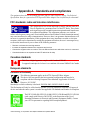
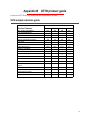
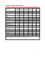
1
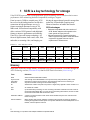
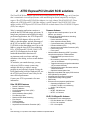
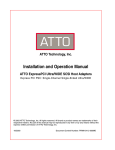
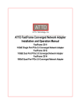
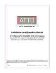
Installation and Operation Manual
ATTO ExpressPCI UL4S
Single Channel Ultra320 SCSI, PCI-X Host Adapter
ATTO ExpressPCI UL4D
Dual Channel Ultra320 SCSI, PCI-X Host Adapter
ATTO ExpressPCI UL5D
Dual Channel Ultra320 SCSI, PCI Express Host Adapter
ATTO ExpressPCI UL5D LP
Dual Channel Ultra320 SCSI, Low-Profile PCIe Host Adapter
© 2007 ATTO Technology, Inc. All rights reserved. All brand or product names are trademarks of their
respective holders. No part of this manual may be reproduced in any form or by any means without the
express written permission of ATTO Technology, Inc.
7/2007
Document Control Number: PRMA-0325-000MD
Contents
1 SCSI is a key technology for storage
1
SCSI advantages
Glossary
2 ATTO ExpressPCI Ultra320 SCSI solutions
3
Ultra 320 SCSI features
Common features
UL4D, UL4S specific features
UL4D Host Adapter specific features
UL4S Host Adapter specific features
UL5D, UL5D LP Host Adapter specific features
UL5D Host Adapter specific features
UL5D LP Host Adapter specific features
SCSI host adapter selection guide
3 Hardware installation
5
System requirements
Installation
3.1 Cabling and termination ......................................................7
Setting up cables and termination
4 Installing drivers
9
5 Updating hardware flash
10
Use the ATTO Configuration Tool
Use the ExpressPCI BIOS Setup Utility
Appendix A Standards and compliances ............................................i
FCC standards: radio and television interference
Canadian standards
European standards
Declaration of Conformity
Appendix B ATTO product guide .........................................................ii
SCSI adapter selection guide
SAS selection guide
Celerity FC adapter selection guide
Appendix C Safety, warranty, contacts ...............................................v
Safety
Installation
Operation
ATTO Technology, Inc. limited warranty
Contact ATTO Technology, Inc.
ATTO Technology Inc.
1 SCSI is a key technology for storage
Ultra320 SCSI represents the seventh generation of SCSI technology, an I/O interface that increases
performance while maintaining backward compatibility and legacy support.
From its roots in 5 MB/sec. transfer rates, SCSI
driving the unprecedented growth in storage that
has evolved as the leading interface for disk drive
pushes the I/O bandwidth, requiring more
connections in high performance servers. It
advanced interfaces to handle data transfer.
features maximum data transfer rates of 320
SCSI advantages
MB/second, full backward compatibility with
• Backward compatible with older versions of
older versions of SCSI protocols and additional
SCSI. Newer adapters will negotiate to the
features to improve performance and reliability.
lower speeds of legacy devices.
•
Minimal
investment to upgrade technology.
Ultra320 is a powerful storage technology. All
Older equipment may still be used with newer
forms of digital content, from e-mail, video, film,
equipment. Upgrade does not require
and audio, to streaming video, and imaging, are
replacement of infrastructure.
Exhibit 1-1
How SCSI has evolved.
Narrow
Fast/
Narrow
Ultra
Ultra/WIDE
Ultra2
Data transfer
rates
<5 MB/sec
10 MB/sec
20 MB/sec
40 MB/sec
80 MB/sec
SCSI protocol
SCSI-1
SCSI-2
SCSI-3
SCSI-3
SCSI-3
SCSI-3
SCSI-3
SPI-1
SPI-1
SPI-1
SPI-2
SPI-3
SPI-4
LVD
LVD
LVD
Specification
SPI-1
Transfer type
SingleEnded
SingleSingleSingleEnded HVD Ended HVD Ended HVD
Ultra160
Ultra320
160 MB/sec 320 MB/sec
Glossary
Some terms used in the storage industry are defined below. More information is available through the
ATTO Technology website (www.attotech.com) and the SCSI Trade Association (www.scsita.org).
Term
Definition
ANSI
American National Standards Institute
Asynchronous
Information
Protection
AIP: although most Ultra320traffic is sent synchronously and protected by CRC, some
information is still sent asynchronously. AIP implements CRC-level error checking on
asynchronous traffic ensuring end-to-end data integrity.
bit
Smallest unit of data a computer can process: a single binary digit with a value of either 0 or 1
byte
an ordered set of 8 bits
CRC
Cyclic Redundancy Checking, an error-correcting code which calculates a numeric value for
received and transmitted data. If no error has occurred during transmission, the CRC for both
received and transmitted data should be the same.
destination address
A value in the frame header of each frame which identifies the port in the node where the
frame is being sent
domain validation
Before sending data, domain validation verifies that the physical connection is capable of
handling the negotiated transfer speed. If the system determines that Ultra320speeds are not
feasible, a slower speed is enforced.
1
ATTO Technology Inc. ExpressPCI Host Adapter Installation and Operation Manual
Term
Definition
double transition
clocking
Increases the data line frequency to equal that of the request signal, allowing sampling on
both the leading and trailing edges of the request signal. Clocking can be set to ensure
compatibility with legacy devices.
flow control
The target indicates to the initiator when the last packet of a data stream will be transferred so
that the initiator can flush FIFOs and terminate pre-fetch sooner than previously possible.
Basically, the target warns the initiator that the transfer is almost complete so that it can
prepare for the next transfer while the target completes the current transfer.
host
A processor, usually a CPU and memory, which communicates with devices over an interface
HVD
High voltage differential: uses two wires, transmitting a signal on one and its inverse on the
other. At the receiving end, the difference between the two signals is measured and
interpreted. Noise on the bus will affect both the signal and its inverse equally, so the
difference between the two lines will remain the same and the noise cannot be misread as a
signal.
initiator device
A component which originates a command
LED
Light-emitting diode: a type of diode that emits light when current passes through it. Visible
LEDs are used as indicator lights on all sorts of electronic devices.
LVD
Low voltage differential. SCSI signalling method that combines the benefits of HVD and
single-ended technologies, allowing longer cabling configurations while consuming less
power than HVD technology.
originator
An initiating device; a component which originates a command
packetization
Creates information units (IUs) from commands, data, status information, etc. which are
passed as synchronous transfers. Maximizes bus use, minimizes command overhead and
allows multiple commands to be transferred in a single connection
pre-compensation
Although SCSI transfer speeds have changed dramatically over the past several generations,
cable specifications have remained constant. Higher speed and frequency signals have a
greater potential for reflection and distortion over distance. Pre-compensation techniques
slightly modify the SCSI signal to reduce the chance of these types of problems.
Quick Arbitration
Select (QAS)
Arbitration
The process of devices negotiating for control of the bus with built-in “quiet times” so that fast
and legacy devices have an opportunity to take control of the bus. A fair, but somewhat
inefficient process, QAS speeds up the arbitration process by eliminating the bus free phase.
When combined with packetization, reduces command overhead and maximizes bus use.
read and write data
streaming
Minimizes data transfer overhead by allowing a target to send one data stream (LQ) packet
followed by multiple data packets. Minimizes overhead of data transfers because the target
can send one data stream packet followed by multiple data packets
receiver
The ultimate destination of data transmission; a terminal device
SCSI
Small Computer Systems Interface: a processor-independent standard for system-level
interface between a computer and intelligent devices including hard disks, floppy disks, CDROM, printers, scanners, etc.
single-ended
An electrical signal protocol that transmits information through changes in voltage. Singleended SCSI uses standard TTL signal and ground pairs to transmit information over the SCSI
bus.
training pattern
SCSI is a parallel bus technology that is dependent on signals being transmitted on parallel
wires simultaneously. At higher speeds, minute differences in wire lengths and transmission
characteristics could cause problems. Training pattern testing measures these minute
differences and compensates for them.
Vpath™ Technology
The ATTO ExpressPCI UL4S with Vpath Technology offers data transfer rates of 320
MB/sec. With one external connector and one internal connector, Vpath Technology allows
both faster and slower devices to run without impacting the speed of faster devices.
2
SCSI is a key technology for storage
2 ATTO ExpressPCI Ultra320 SCSI solutions
The Ultra320 SCSI Host Adapter represents the seventh generation of SCSI technology, an I/O interface
that is committed to increased performance while maintaining backward compatibility and legacy
support. The ATTO ExpressPCI UL4S Host Adapter is a single channel Ultra320 SCSI, PCI-X host
adapter, the ATTO ExpressPCI UL4D Host Adapter is a dual channel Ultra320 SCSI, PCI-X host
adapter, and the ATTO ExpressPCI UL5D and UL5D LP are dual channel Ultra 320 SCSI PCI Express
(PCIe) host adapters.
Today’s computing applications continue to
strain the host PCI bus and storage subsystem. To
bring better performance and reliability to today’s
professional applications, the ATTO ExpressPCI
UL4D and UL4S adapters deliver up to 640
MB/sec. data throughput, and take advantage of
the PCI-X bus interface while the ExpressPCI
UL5D delivers data throughput rates of up to 640
MB/sec. using the latest in PCI bus technology,
PCIe. ATTO ExpressPCI UL4D, UL4S, UL5D
and UL5D LP adapters deliver the high
bandwidth demanded in data-intensive
environments such as real-time and highdefinition video editing, web server and database
engines.
To maximize your attached storage, you may
wish to use RAID, a storage system using
multiple disk drives to improve storage
productivity and efficiency. Instead of using the
RAID functionality built into Windows® OS, use
the ATTO Express PowerCenter Utility for the
most efficient performance.
Contact your ATTO representative for more
information.
Common features
•
•
•
•
•
•
•
•
•
Ultra 320 SCSI features
•
•
•
•
•
•
•
•
•
•
•
Double Transition Clocking
Domain Validation
Cyclic Redundancy Check (CRC)
Packetization
Quick Arbitration Select (QAS)
Free-Running Clock
Read and Write Data Streaming
Flow Control
Training Pattern
Pre-Compensation
Asynchronous Information Protection (AIP)
•
Supports data transfer speeds of up to 320
MB/sec. per channel
Supports Ultra320 Specifications including:
• Packetized SCSI
• Double transition clocking
• Quick Arbitration Select (QAS)
• Cyclical Redundancy Checking (CRC)
• Domain Validation (DV)
• Asynchronous Information Protection (AIP)
• Free-running clock
• Flow control
Advanced Data Streaming (ADS™) provides
controlled acceleration of data transfers.
• Embedded RISC processor for low
overhead
• Bus mastering eliminates CPU processing
time as a bottleneck
• Tagged command queuing allows threads to
be processed efficiently
• Disconnect/reconnect eliminates wait time
between transfers
• Optimized scatter/gather lists
Backward compatible with legacy SCSI devices
ASPI (Windows) compatible
Automatic and upper-byte termination
Flash ROM for easy field upgrades
RAID ready
Environment and physical specifications
• Operating temperature: 0-45oC
• Humidity: 10-90% non-condensing
• Airflow: 100 LFM (min.)
Reliability
• MTBF: 150,000 hours
• MTTR: <15 minutes
UL4D, UL4S specific features
•
Accelerated PCI bus management
• PCI Bus Master rate of 1-GB/sec.
• PCI-X 1.0a compliant
• PCI 2.2 compliant
3
ATTO Technology Inc. ExpressPCI Host Adapter Installation and Operation Manual
UL5D, UL5D LP Host Adapter specific
features
•
•
64-bit/133 Mhz PCI-X (backward compatible
with standard PCI)
Power
• 0.75 typical/2.0 max. Amps @ + 5.0 /VDC
• 0.05 Amps @ + 12.0 VDC
•
•
UL4D Host Adapter specific features
•
•
•
Two external VHDCI and two internal highdensity 68-pin connectors
Supports up to 30 SCSI bus IDs (15 per channel)
Dimensions
• Length: 6.521”
• Height: 4.450”
UL5D Host Adapter specific features
•
•
•
UL4S Host Adapter specific features
•
•
Supports up to 30 SCSI bus IDs (15 per channel)
PCI Express (PCIe) bus management
• PCI Bus master rate 2-GB/sec.
• PCI Express 1.0b compliant
One external high-density 68-pin connector and
one internal high-density 68-pin connector
Dimensions
• Length: 6.521”
• Height: 4.200”
Two external VHDCI and two internal highdensity connectors.
Dimensions
• Length: 7.5”
• Height: 4.376 “
Power
• 1.61 typical/2.03 max. Amps @ +3.3 VDC
• 0.65 typical/1.46 Amps @ + 12.0 VDC
UL5D LP Host Adapter specific features
•
•
•
•
Dual stacked external VHDCI connectors.
Dimensions
• Length: 6.6”
• Height: 2.713”
Power
• 0.55 typical/0.9 max. Amps @ +3.3 VDC
• 0.56 typical/0.59 max. Amps @ + 12.0 VDC
Low-profile bracket available
SCSI host adapter selection guide
Single Channel
Dual Channel-- 2 independent channels
ExpressPCI Ultra 320
ExpressPCI Ultra 320
ExpressPCI Ultra 320
320 MB/sec
640 MB/sec
640 MB/sec
LVD
•
•
•
64-bit (PCI)
•
•
•
•
Max. transfer rate
32-bit (PCI)
33 MHZ (PCI)
133 MHZ (PCI-X)
•
x4 PCIe
Bus ID support
Part number
•
•
•
•
30
30
30
EPCI-UL4S
EPCI-UL5D EPCI-UL5D LP
EPCI-UL4D
4
ATTO ExpressPCI Ultra320 SCSI solutions
3 Hardware installation
Install the ATTO ExpressPCI Ultra320 Host Adapter and attach your SCSI devices to it using the
instructions below. To get the best performance from your ATTO Express Ultra320 host adapters, use
Ultra 320 SCSI devices.
Devices in the middle of the bus, including the
ATTO ExpressPCI adapter, must have
termination removed or disabled. ATTO
ExpressPCI SCSI adapters select the proper
termination if left in auto termination mode.
CAUTION
Remember to back up your system data
before changing or installing hardware.
System requirements
The ATTO ExpressPCI host adapter package
contains the host adapter, the ATTO ExpressPCI
CD and a warranty and registration card. If any
items are missing, contact your ATTO authorized
sales representative.
To install and use the ATTO ExpressPCI UL4D
and UL4S SCSI adapters you need:
•
A computer with an available 64-bit PCI-X
expansion slot (preferred) or a standard 32- or
64-bit PCI expansion slot.
•
The complete ATTO ExpressPCI SCSI host
adapter package.
3
If you need to change this setting, refer to the
ATTO Utilities Installation and Operation
manual. Also refer to your SCSI device
documentation to determine the current SCSI
ID and how to change it. Wide (16-bit) SCSI
devices can be assigned IDs 0 to 7 and 8 to 15,
while Narrow (8-bit) devices can only be
assigned IDs ranging from 0 to 7.
4
Review system documentation to select an
appropriate slot to install your adapter. The
combined power consumption of the expansion
slots must not exceed the limits for your
system. If you have more than one expansion
card installed, ensure power consumption is
within the limits outlined for your system.
5
Power down the computer and unplug the
computer from all power sources.
6
Open the case.
7
Install the adapter in any open PCI expansion
To install and use the ATTO ExpressPCI UL5D
and ExpressPCI UL5D LP you will need
•
A computer with an available x4 PCIe expansion
slot or larger, such as x8 or x16.
•
The complete ATTO ExpressPCI SCSI host
adapter package.
CAUTION
ATTO ExpressPCI host adapters contain
components that are sensitive to
electrostatic discharge (ESD). ESD can
cause damage to the ExpressPCI host
adapter. Please follow standard methods
to avoid ESD.
Installation
Remember to back up your system data before
changing or installing hardware.
1
Plan your SCSI device connections.
If connecting both internal and external devices
to the ATTO ExpressPCI SCSI adapter, be sure
to have the appropriate cables to connect
devices.
2
Set SCSI device termination. Devices at both
ends of the SCSI bus must be terminated.
Set SCSI IDs. Each device on the SCSI bus
requires a unique SCSI ID, one different from
the host adapter ID. The default setting for the
ATTO ExpressPCI adapter is 7.
slot. Consult your computer’s documentation if
you have questions about how to install an
expansion card in your system.
8
Connect SCSI devices by inserting a SCSI
cable to the connector on the ATTO
ExpressPCI host adapter until you hear a click.
Refer to Chapter 3.1 when selecting cables.
9
Close the computer case and power it up.
ATTO ExpressPCI host adapters come
preconfigured to operate properly in a variety of
common system setups. However, some systems
may benefit by tuning the adapter for optimal
performance. Refer to the ATTO Utilities
Installation and Operation manual for more
information on changing host adapter settings.
5
ATTO Technology Inc. ExpressPCI Host Adapter Installation and Operation Manual
6
Hardware installation
3.1 Cabling and termination
Cables and devices must be chosen to maximize performance and minimize the electrical noise from the
high-speed data transfers available with the SCSI protocol. Cabling and termination methods become
important considerations.
Exhibit 3.1-1 The following table lists the maximum number of devices you may connect at specific cable distances
using differential and single-ended SCSI in various SCSI environments.
Max. bus lengths, meters
Bus speed Bus width
MB/sec. max.
bits
Single-ended
LVD
HVD
Max. device
support
5
8
6
-
25
8
Fast SCSI
10
8
3
-
25
8
Fast Wide SCSI
20
16
3
-
25
16
Wide Ultra/WIDE SCSI
40
16
-
-
25
16
Wide Ultra/WIDE SCSI
40
16
1.5
-
-
8
Wide Ultra/WIDE SCSI
40
16
3
-
-
4
Ultra2 SCSI
SCSI-1
80
16
-
12
-
16
Ultra160 SCSI
160
16
-
12
-
16
Ultra320 SCSI
320
16
-
12
-
16
Setting up cables and termination
Use high quality Ultra 320-rated, well-insulated
SCSI cables to ensure error free communications.
Exhibit 3.1-2
connectors.
Several internal and external cable
Voltage Differential (LVD) and Single-Ended.
Devices on the same SCSI bus must use the same
signaling, either LVD or Single-Ended.
To set up cabling and termination:
1
2
•
The ExpressPCI Ultra320 SCSI Host Adapter
supports two types of SCSI signaling: Low
3
Determine whether you are using a single
channel or dual channel host adapter model.
One external connector indicates a single
channel host adapter; two external connectors
indicate a dual channel host adapter.
Determine if SCSI devices are going to be
installed internally or externally.
Total bus cable length varies by host adapter
and type of attached devices. Refer to
Exhibit 3.1-1 for details on maximum cable
length.
•
If you combine Wide 16-bit and Narrow 8bit devices on the same connector, connect
the Wide devices first (closest to the
connector).
•
Refer to the documentation for your SCSI
devices to determine if they are Wide or
Narrow, UltraWIDE SCSI, Ultra2 SCSI,
Ultra160 or Ultra 320.
Determine which terminator to use
7
ATTO Technology Inc. ExpressPCI Host Adapter Installation and Operation Manual
•
A narrow terminator should be used on the
last narrow device to terminate the rest of the
SCSI bus.
Use an LVD terminator if you are only using LVD
devices.
Although you can use a Single-Ended
terminator, all devices will be limited to Ultra
SCSI speeds. Single-Ended devices require
a Single-Ended terminator.
If you use an LVD terminator with SingleEnded devices, the system may hang or
devices may not be seen on the SCSI bus.
A SCSI bus without partial termination
between the wide and narrow devices may at
first appear to work correctly, but occasional
I/O errors occur without proper termination.
•
Some termination manufacturers provide
automatically sensing terminators.
•
External terminators should be attached to the
last external device in the SCSI chain.
•
When both internal and external connectors
are used, the host adapter card detects the
presence of devices and turns off
termination.
Don’t use any other termination on the
external SCSI chain.
The last device on an internal SCSI chain
should also be terminated in one of several
ways.
Many Single-Ended Ultra SCSI and earlier
devices provide a jumper setting for applying
termination: place a jumper over the pins
designated for termination on the last device
on the internal cable. Check with your drive
manufacturer if you are not sure which pins
to use.
•
If devices are removed from one connector
of the card, the host adapter automatically
detects the change, and enables its own
termination.
•
The host adapter must supply partial
termination to the upper 8-bits (byte), but not
automatically.
Use an internal ribbon cable which has a
SCSI terminator attached to the end of it,
connect the unterminated end of the cable to
the host adapter card and the internal drives
to the subsequent connectors.
•
Wide (16-bit) and Narrow (8-bit) devices can be
connected together on the same connector of
the host adapter card, but wide devices must be
attached first, followed by narrow devices.
To terminate the SCSI bus, the cable or
adapter used to convert from a wide (68-pin)
connector to a narrow (50-pin) connector
provides partial termination, allowing upper
8-bits (or byte) of the wide SCSI bus to be
properly terminated.
Software controlled termination
You may have to override the host adapter’s
automatic termination if only narrow devices
are attached to one connector and wide
devices are attached to the other connector
on the same bus.
LVD Ultra2 and Ultra160 SCSI devices cannot
supply their own termination.
The terminator should be at the opposite end
of the cable from the host adapter card.
If you use both internal and external connectors
and mix Single-Ended and LVD devices on the
same bus, even if using different connectors, the
host adapter card will operate with Single-Ended
signaling at UltraSCSI speeds.
Automatic termination
Please refer to your ATTOI Utilities manual
for instructions on setting the host adapter’s
termination to Upper Byte.
•
Termination power
Host adapters supply termination power to
the bus at all times and many SCSI devices
are also able to supply termination power.
SCSI signal quality, particularly with long or
marginal quality cables, may be improved if
the device supplies the termination power.
Contact your device manufacturer for more
information on your device’s ability to supply
termination power.
8
Cabling and termination
4 Installing drivers
After installing the ATTO ExpressPCI Host Adapter, you must configure your system to recognize and
use it by installing drivers for your operating system.
Note
If you already have one or more ExpressPCI
adapters installed and you are installing
additional adapter(s), you do not need to
perform any of these procedures unless you
are updating a previously installed driver.
After installing the ATTO ExpressPCI Host
Adapter, you must configure your system to
recognize and use it by
•
•
installing drivers for your operating system
updating the adapter firmware if necessary
ATTO ExpressPCI adapters ship with the latest
firmware installed. If you are performing a new
adapter installation, you do not need to update the
firmware. If you are upgrading a previously
installed driver, update the adapter firmware to
ensure proper operation.
1
Go to the Support Downloads menu item in
the ATTO Technology website,
www.attotech.com
2
In the ExpressPCI Host Adapters menu item,
find your ExpressPCI adapter and click on
Download.
3
Find your operating system menu item
•
Mac OS X ExpressPCI Drivers
•
Windows ExpressPCI Drivers
•
Linux Support for ExpressPCI
•
Novell Netware ExpressPCI drivers
4
Download the appropriate driver.
5
For the Novell Netware ExpressPCI Drivers
menu, select the readme.txt file
For all other drivers, release notes and
installation instructions are included in the
download packages.
6
Follow the installation instructions.
7
Update the adapter firmware using the ATTO
Configuration Tool or the ExpressPCI BIOS
Setup Utility. Refer to Use the ATTO
Configuration Tool and Use the ExpressPCI
BIOS Setup Utility on page 10.
9
ATTO Technology Inc. ExpressPCI Host Adapter Installation and Operation Manual
5 Updating hardware flash
ATTO ExpressPCI adapters ship with the latest firmware installed. If you are performing a new adapter
installation, you do not need to update the firmware. If you are upgrading a previously installed driver,
update the adapter firmware to ensure proper operation.
Visit the ATTO Technology website,
Use the ExpressPCI BIOS Setup Utility
www.attotech.com, for the latest drivers and
Note
firmware.
BIOS utilities are not available on Itanium
systems. Use the ATTO Configuration Tool
to update flash on Itanium systems.
Use the ATTO Configuration Tool
1
2
Download the most recent version of the
Configuration Tool from the ATTO web site,
www.attotech.com.
1
Download the latest Windows driver package
from the ATTO Technology website.
Refer to the ATTO Utilities Installation and
Operation Manual for additional information on
downloading and using the Configuration Tool.
2
Run makedisk.bat in the Windows driver
package and follow the instructions for creating
the driver floppy disk.
Download the flash bundle for your adapter
from the ATTO web site and extract them to
your desktop.
3
Reboot the PC.
4
During the reboot, an ATTO Technology
banner displays that the host adapter is
detected.
5
Enter Control-Z when prompted to begin the
setup utility within a few seconds after the
banner appears.
3
Install the Configuration Tool on your system.
4
Launch the Configuration Tool.
5
In the Device window, select your adapter
6
In the Flash window, click on the Browse
button to find the flash bundle that you
previously downloaded to your desktop.
7
Click Update to update your flash ROM.
6
In the utility, select the Adapter Menu.
8
Reboot your system for the flash changes to
take effect.
7
Select the Upgrade Flash ROM option.
8
Insert the driver disk from step 1 into the floppy
drive.
9
Follow the on-screen instructions.
If you do not enter Control-Z soon enough after
the banner appears, repeat steps 3-5.
10 Remove the disk and reboot your system for
the flash ROM changes to take effect.
10
Updating hardware flash
Appendix A Standards and compliances
The equipment described in this manual generates and uses radio frequency energy. The Technical
Specification sheet for a particular ATTO ExpressPCI Host Adapter lists certifications for that model.
FCC standards: radio and television interference
This equipment has been tested and found to comply with the limits for a
Class A digital device, pursuant to Part 15 of the FCC Rules. These limits
are designed to provide reasonable protection against harmful interference
in a residential installation. This equipment generates, uses, and can
radiate radio frequency energy and, if not installed and used in accordance with the instruction manual,
may cause interference to radio communications. However, there is no guarantee that interference will
not occur in a particular installation. If this equipment does cause interference to radio or television
reception, which can be determined by turning the equipment off and on, the user is encouraged to try
to correct the interference by one or more of the following measures:
•
Reorient or relocate the receiving antenna
•
Increase the separation between the equipment and receiver
•
Connect the equipment into an outlet on a circuit different from that to which the receiver is connected
•
Consult the dealer or an experienced radio/TV technician for help
Canadian standards
This Class A digital apparatus complies with Canadian ICES-003.
Cet appareil numérique de la classe A est conforme à la norme NMB-003 du Canada.
European standards
Declaration of Conformity
This following statement applies to the ATTO ExpressPCI Host Adapter.
This device has been tested in the basic operating configuration and found to be
compliant with the following European Union standards: Application of Council
Directive: 89/336/EEC
Standard(s) to which conformity is declared: EN55024:2002; EN55022:2002 CLASS B
This Declaration will only be valid when this product is used in conjunction with other CE approved
devices and when the entire system is tested to the applicable CE standards and found to be compliant.
The EPCI-UL4D-0R0, EPCI-UL4S-0R0, EPCI-UL5D-0R0 and EPCI-UL5D-L00
cards comply with Directive 2002/95/EC on the Restriction of the Use of
Hazardous Substances in Electrical and Electronic Equipment (RoHS). Contact
your ATTO representative regarding RoHS compliant products.
i ATTO Technology, Inc. ExpressPCI Host Adapter Installation and Operation Manual
Appendix B ATTO product guide
Contact an ATTO Technology authorized sales representative to order.
SCSI adapter selection guide
Ultra 320 SCSI
Product Features
UL5D
UL5D LP
UL4D
UL4S
640
640
640
320
•
•
•
•
•
•
•
•
2/2
30
0/2
30
2/2
30
1/1
30
Large file transfers
•
•
•
•
•
Cable distances (m)
12.5
12.5
12.5
12.5
•
•
•
•
•
•
•
•
•
•
Max. transfer rate (MB/sec.)
Low Voltage Differential
Single-ended SCSI
Number of SCSI Channels
Number of SCSI IDs supported
Low profile
32-bit PCI compatible
64-bit PCI compatible
33 MHZ PCI
133 MHZ PCI-X
66 MHz PCI
x4 PCI Express
Windows 2000/XP, Server 2003/Vista
support
Linux support
Mac OS X support
Novell Netware support
RoHS compliant
•
•
•
•
•
•
•
•
•
•
•
•
•
•
•
•
•
•
•
•
•
•
ii
SAS selection guide
Product Features
1
Max.transfer rate (full duplex)
x8 PCI Express
Number of ports
Port configuration external/internal
Connector type
Number of devices supported
ATTO ExpressSAS RAID Adapters
R348
R380
4 GB/sec.
4 GB/sec.
•
•
8
8
4/8
8/0
user selectable 4/4 or 0/8
1 mini SAS (x4) SFF-8088 external 2 mini SAS (x4) SFF-8088 external
2 mini SAS (x4) SFF-8087 internal
64 SAS/SATA targets
64 SAS/SATA targets
128 virtual devices
128 virtual devices
•
•
•
•
•
•
up to 8m
0, 1, 4, 5, 62, 10, 50, 602, JBOD,
DVRAID
up to 8m
0, 1, 4, 5, 62, 10, 50, 602, JBOD,
DVRAID
•
•
•
•
E-mail, pop-up, log file
258 MB standard
512 upgradeable (OEM)
E-mail, pop-up, log file
258 MB standard
512 upgradeable (OEM)
•
•
Battery backup
optional
optional
32-bit support
•
•
•
•
•
•
•
•
•
•
•
•
•
•
1.5 Gb SATA support
3 Gb SATA II support
3 Gb SAS support
Cable distances
Integrated RAID
RAID Management Utility
Global Hot Spares
Event notification
Memory (ECC)
Advanced Data Streaming™
64-bit support
Windows 2000/CP, Server
2003/Vista support
Linux (Red Hat, SUSE) support
Mac OS X support
RoHS compliant
Low profile
1
Performance ceiling constrained by PCIe bus transfer speed
2
Future support
iii ATTO Technology, Inc. ExpressPCI Host Adapter Installation and Operation Manual
Celerity FC adapter selection guide
Celerity
FC-44ES
Product Features
Fibre Channel Ports
FC protocol
Maximum Transfer Rate (half
duplex)
Maximum Transfer Rate (fullduplex)
Bus Type
3
Bus Characteristics
Optical Interface
Maximum Cable Length
Celerity
FC-42ES
FC-42EN
Celerity
FC-41ES
FC-41EN
Celerity
FC-42XS
Celerity
FC-41XS
Celerity
FC-21PS
4
2
1
2
1
1
4-Gb
4-Gb
4-Gb
4-Gb
4-Gb
2-Gb
1.6 GB/sec
800 MB/sec
400 MB/sec
800 MB/sec
400 MB/sec
200 MB/sec
2 GB/sec
1 GB/sec (ES)
1.6 GB/sec (EN)
800 MB/sec
1 GB/sec1
800 MB/sec
400 MB/sec
PCIe
PCIe
PCIe
PCI-X
PCI-X
PCI-X
64-bit
133 MHz2
64-bit
133 MHz2
8 lane
4 lane
4 lane
64-bit
133 MHz2
SFP LC
SFP LC
SFP LC
SFP LC
SFP LC
SFF LC
300m@2-Gb
150m@4-Gb
300m@2-Gb
150m@4-Gb
300m@2-Gb
150m@4-Gb
300m@2-Gb
150m@4-Gb
300m@2-Gb
150m@4-Gb
500m@1-Gb
300m@2-Gb
•
•
•
•
•
Low Profile form factor
ATTO Advanced Data Streaming
(ADS) Technology
•
•
•
•
•
•
Software RAID support3
•
•
•
•
•
•
Developer's Kit (Target Mode &
API)
Windows XP, 2000, Server 2003
and Vista support
•
•
•
•
•
•
•
•
•
•
•
•
Linux (Red Hat, SUSE) driver
•
•
•
•
•
•
Macintosh OS X driver
•
•
•
•
•
•
Novell Netware support
•
•
•
•
•
Solaris support
•
•
•
•
•
Free BSD
•
•
•
•
•
RoHS compliant
•
•
•
•
•
1 Performance ceiling is constrained by 133 MHz PCI-X bus transfer speed
2 Backward compatible to 32-bit and 33 MHz PCI; FC-21PS is 3.3V/5V Universal
3 ATTO ExpressStripe for OS X available; Express Power Center and other software RAID supported for Windows
iv
Appendix C Safety, warranty, contacts
All ATTO host adapter products have been tested to meet applicable safety standards when operated in
proper electrical and thermal environments.
Safety
Please review the specifications for your specific host adapter before installing and operating it in any
computer system to ensure compatibility.
Installation
Before installing an ATTO host adapter product into your computer system, unplug the computer from
its electrical power source and allow adequate time for electrical discharge and the internal components
to cool down before removing the computer system cover. This will decrease the risk of personal injury
from electrical shock or touching the hot surface of an electrical component.
Once an ATTO host adapter is installed in a computer system, the computer cover must be reinstalled
properly before turning the computer system back on.
Operation
ATTO host adapters require adequate cooling to function properly. If you have any questions as to the
airflow provided by your computer system, please refer to your computer system manual or contact your
computer system manufacturer.
To facilitate proper air circulation, ATTO host adapters should never be operated in a computer system
without the cover installed or with an inoperable fan as this may cause safety or thermal problems which
could damage the ATTO host adapter and void the warranty.
ATTO Technology, Inc. limited warranty
ATTO Technology, Inc. warrants to the original purchaser of this product that it is free from defects in
material and workmanship as described in the ATTO Technology website, www.attotech.com.
ATTO Technology, Inc. liability shall be limited to replacing or repairing, at its option, any defective
product. There is no charge for parts or labor should ATTO Technology, Inc. determine that this product
is defective.
Products which have been subject to abuse, misuse, alteration, neglected, or have been serviced, repaired
or installed by unauthorized personnel shall not be covered under this warranty provision. Damage
resulting from incorrect connection or an inappropriate application of this product shall not be the
responsibility of ATTO Technology, Inc. Liability is limited to ATTO Technology, Inc.product(s);
damage to other equipment connected to ATTO Technology, Inc.product(s) is the customer’s
responsibility.
This warranty is made in lieu of any other warranty, express or implied. ATTO Technology, Inc.
disclaims any implied warranties of merchantability or fitness for a particular purpose.
v ATTO Technology, Inc. ExpressPCI Host Adapter Installation and Operation Manual
ATTO Technology, Inc. responsibility to repair or replace a defective product is the sole and exclusive
remedy provided to the customer for breech of this warranty. ATTO Technology, Inc. is not liable for
any indirect, special, incidental, or consequential damages irrespective of whether ATTO Technology,
Inc. has advance notice of the possibility of such damages.
No ATTO Technology, Inc. dealer, agent or employee is authorized to make any modification,
extension or addition to this warranty.
Contact ATTO Technology, Inc.
Customer service, sales information and technical support are available by phone Monday through
Friday, Eastern Standard Time 8:00 a.m. to 8:00 p.m., or by e-mail and website 24-hours a day.
ATTO Technology, Inc.
155 CrossPoint Parkway
Amherst, New York 14068
(716) 691-1999 • voice
(716) 691-9353 • fax
http://www.attotech.com
ATTO Technology can also be reached via e-mail at the following addresses:
Sales Support:
[email protected]
Technical Support: [email protected]
vi
vii ATTO Technology, Inc. ExpressPCI Host Adapter Installation and Operation Manual