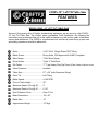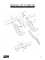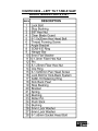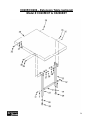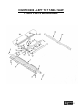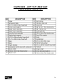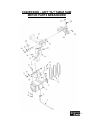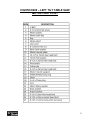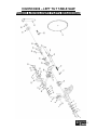
1
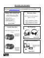
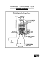
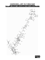
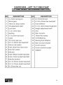
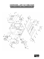
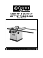
CX205-10” & CX206-12” LEFT TILT TABLE SAWS User Manual Table of Contents General Safety Instructions..................................................................................... 3 Specific Safety Instructions..................................................................................... 4 CX205 Features...................................................................................................... 5 CX206 Features...................................................................................................... 6 Physical Features ................................................................................................... 7 Set Up..................................................................................................................... 8 Un-Packing & Inventory .......................................................................................... 8 Proper Grounding ................................................................................................... 9 Assembly Motor Cabinet .........................................................................................................10 Hand Wheels .......................................................................................................... 10 Extension Wings .....................................................................................................10 Fence Rails ............................................................................................................. 11 Fence Assembly & Miter Gauge ............................................................................. 11 Magnetic Switch......................................................................................................12 Installing the Blade.................................................................................................. 12 Fence Tape Scale................................................................................................... 13 Blade Guard & Anti-Kick Back Pawls......................................................................13 Table Insert ............................................................................................................. 14 Arbor Extension ...................................................................................................... 14 Connecting to a Dust Collector ............................................................................... 14 Basic Controls.........................................................................................................15 Test Run ................................................................................................................. 15 Adjustments Blade Alignment...................................................................................................... 16 Blade Height Adjustment ........................................................................................ 16 Blade Tilt Adjustment .............................................................................................. 16 Fence Adjustment ................................................................................................... 16 Adjusting the Riving Knife ....................................................................................... 17 Miter Gauge Adjustment ......................................................................................... 17 Operations Rip Cutting .............................................................................................................. 18 Cross Cutting .......................................................................................................... 18 Miter Cutting ........................................................................................................... 18 Maintenance .......................................................................................................... 19 Optional Accessories .............................................................................................. 20 Wiring Diagram ....................................................................................................... 21 Parts Breakdown & List.......................................................................................22-32 Warranty ................................................................................................................. 33 2 GENERALSAFETY INSTRUCTIONS Extreme caution should be used when operating all power tools. Know your power tool, be familiar with its operation, read through the owner’s manual and practice safe usage procedures at all times. ALWAYS read and understand the user manual before operating the machine. CONNECT your machine ONLY to the matched and specific power source. ALWAYS wear safety glasses respirators, hearing protection and safety shoes, when operating your machine. DO NOT wear loose clothing or jewelry when operating your machine. A SAFE ENVIRONMENT is important. Keep the area free of dust, dirt and other debris in the immediate vicinity of your machine. BE ALERT! DO NOT use prescription or other drugs that may affect your ability or judgment to safely use your machine. DISCONNECT the power source when changing drill bits, hollow chisels, router bits, shaper heads, blades, knives or making other adjustments or repairs. NEVER leave a tool unattended while it is in operation. NEVER reach over the table when the tool is in operation. ALWAYS keep blades, knives and bits sharpened and properly aligned. ALL OPERATIONS MUST BE performed with the guards in place to ensure safety. ALWAYS use push sticks and feather boards to safely feed your work through the machine. ALWAYS make sure that any tools used for adjustments are removed before operating the machine. ALWAYS keep the bystanders safely away while the machine is in operation. NEVER attempt to remove jammed cutoff pieces until the saw blade has come to a full stop. 3 CX205/CX206 SPECIFIC SAFETY INSTRUCTIONS NEVER use a saw blade that has missing carbide teeth, loose teeth, or chipped or broken teeth. NEVER stand directly in line with the saw blade when feeding stock into the saw. NEVER place your fingers or hands in the line of cut. If you slip, your hands or fingers may come into contact with the blade. Always use a push stick when ripping narrow pieces. NEVER allow visitors or helpers to stand in line with the saw blade. DO NOT attempt to remove jammed pieces unless the table saw has come to a complete stop and the power switch has been turned to the OFF position and cord is unplugged. NEVER attempt to cut stock “freehand”, always use the rip fence or miter gauge. ALWAYS make sure that the rip fence is properly squared to the saw blade to prevent kickback. ALL GAURDS must be in place while operating the table saw to ensure safety. ALWAYS make sure that your saw is in a stable position. Cutting heavy, long stock may alter the stability of the saw. In the event that this may occur, the saw should be firmly bolted to the floor. ALWAYS feed the stock smoothly. Do not force or twist the work-piece while cutting. ALWAYS be sure that if using a mobile base, wheels are firmly locked before turning the saw on. NEVER allow anyone to “assist” you by holding your work-piece at the outfeed end. ALWAYS use a feather board and/or hold-downs to support your work-piece when necessary. MAKE SURE before making any adjustments, the switch is in the “OFF” position and the cord is un-plugged. MAKE SURE you have read and understood all the safety instructions in the manual and you are familiar with your table saw, before operating it. If you fail to do so, serious injury could occur. NEVER LEAVE the table unattended while it is running. saw WARNING The safety instructions given above can not be complete because the environment in every shop is different. Always consider safety first as it applies to your individual working conditions. 4 CX205–10” Left Tilt Table Saw FEATURES MODEL CX205 – 10” LIFT TILT TABLE SAW As part of the growing line of Craftex woodworking equipment, we are proud to offer CX205 10” Left Tilt Table Saw. The Craftex name guarantees Craft Excellence. By following the instructions and procedures laid out in this owner’s manual, you will receive years of excellent service and satisfaction. The CX205 is a professional tool and like all power tools, proper care and safety procedures should be adhered to. Motor .............................................. 3-HP, 220-V, Single Phase TEFC Motor Blade Guard ...................................Riving Knife, CSA Approved & UL897 Compliant Mitre Gauge.................................... T-Slot Mitre Gauge Drive System .................................. Triple “V” Belt Drive Rip Fence .......................................“T” Type Heavy Duty Rip Fence (Cam Lever) w/Optical Cursor Arbor Extension ..............................Included Table Size....................................... 27” x 36” (with Extension Wings) Arbor Tilt ......................................... Left Tilting Blade Speed ................................... 4,140 RPM Floor to Table Height ...................... 35” Maximum Depth of Cut @ 90°........ 3” Maximum Depth of Cut @ 45° ........ 2 1/8” Dust Collection Ports ...................... One 4” Port Base Dimensions............................ 25 x 32” Blade Size ...................................... 10” Approximate Weight ....................... 175 Kgs CX206–12” Left Tilt Table Saw FEATURES MODEL CX206 – 12” LEFT TILT TABLE SAW As part of the growing line of Craftex woodworking equipment, we are proud to offer CX206 12” Left Tilt Table Saw. The Craftex name guarantees Craft Excellence. By following the instructions and procedures laid out in this owner’s manual, you will receive years of excellent service and satisfaction. The CX206 is a professional tool and like all power tools, proper care and safety procedures should be adhered to. Motor .............................................. 3-HP, 220-V, Single Phase TEFC Motor Blade Guard ...................................Riving Knife, CSA Approved & UL897 Compliant Mitre Gauge.................................... T-Slot Mitre Gauge Drive System .................................. Triple “V” Belt Drive Rip Fence .......................................“T” Type Heavy Duty Rip Fence (Cam Lever) w/Optical Cursor Arbor Extension ..............................Included Arbor Tilt ......................................... Left Tilting Table Size....................................... 30” x 48” (with Extension Wings) Blade Speed ................................... 4,140 RPM Floor to Table Height ...................... 35” Maximum Depth of Cut @ 90 ° ....... 4” Maximum Depth of Cut @ 45 ° ....... 2 5/8” Dust Collection Ports ...................... One 4” Port Base Dimensions............................ 30” x 48” Blade Size ...................................... 12” Approximate Weight ....................... 280 Kgs 6 CX205/CX206 – Left Tilt Table Saw Physical Features Blade Guard Fence Miter Gauge Magnetic Switch Rear Fence Rail Front Fence Rail Blade Tilt Lock Blade Height Lock Blade Height Hand Wheel Fence Lock Knob Blade Tilt Hand Wheel 7 SETUP List of Contents Before setting up your machine you should read and understand the instructions given in this manual. The unpainted surfaces of this table saw are coated with rust prevention waxy oil and you will want to remove this before you begin assembly. Use a solvent cleaner that will not damage painted surfaces. A. B. C. D. E. F. Table Saw........................................ Table Extensions ............................. Cabinet Door.................................... Rip Fence ........................................ Front & Rear Rails ........................... Blade................................................ 1 2 1 1 3 1 WARNING CX205/CX206 is a very heavy machine, do not over-exert yourself. For safe moving method use fork truck or get the help of an assistant or friend. UNPAKING The machine properly packaged and is shipped completely in 3 crates for safe transportation. When unpacking, carefully inspect the crate and ensure that nothing has been damaged during transit. Open the crate and check that the machine is in a good condition. Figure-2 Inventory List of Contents Figure-1 Inverntory G. H. I. J. K. L. M. N. O. P. Q. R. Miter Gauge ..................................... Blade Guard..................................... Push Stick........................................ Lock Knob........................................ Hand-wheel...................................... Dado Insert ...................................... Extension Table Legs (Optional)..... Extension Table (Optional) ............. Arbor Wrench................................... Anti Kickback Pawl........................... Legs Connecting Rod (Optional)..... Hardware Bag .................................. 1 1 1 1 2 1 2 1 1 1 1 1 8 Proper Grounding Grounding provides a path of least resistance for electric current to reduce the risk of electric shock. CX205 is equipped with a 220-V single phase motor and provided with a power supply cord that is to be connected directly to the source. See figure-3. CX206 is equipped with a 220-V single phase motor and features a terminal block in the electrical connection box and is not supplied with a power cord. Make sure that the machine is connected to an outlet having the same configuration. If an adaptor plug is used, it must be attached to the metal screw of the receptacle. To prevent electrical hazards, have a qualified electrician ensure that the line is properly wired. WARNING Improper connection of the equipmentgrounding conductor can result in a risk of electric shock. Check with a qualified electrician if you are in doubt as to whether the outlet is properly grounded. It is strongly recommended not to use extension cords with your CX205/CX206. Always try to position your machine close to the power source so that you do not need to use extension cords. When it is necessary to use an extension cord, make sure the extension cord does not exceed 50-feet in length and the cord is 12-gauge to prevent motor damage. Your CX205/CX206 should be wired with a plug having 3-prongs to fit a 3 prong grounded receptacle as shown in figure-3. Do not remove the grounding prong to fit it into a 2-pronged outlet. Always check with a qualified electrician if you are in doubt. Figure-3 220-Volts Outlet for CX205/CX206 9 ASSEMBLY CX205/CX206 features 4 mounting holes on its base. To mount and level the table saw on your shop floor, shimming may be required. Mounting the saw to the floor reduces vibration and increases stability. shaft secure it with a set screw provided. See figure-5 IMPORTANT Place the table saw on a flat and level surface, and make sure that the mobile base is locked before proceeding to assembly if using a mobile base. Motor Cabinet Figure-5 Installing blade height hand wheel Take the motor cabinet and attach it to the table saw by inserting the hinge pins into the hinge sockets on the cabinet. See figure-4 Insert the crank handle into the hand wheel shaft and secure it by rotating a few turns. Figure-6 Installing blade tilt hand wheel Figure-4 Installing the motor cabinet Extension Wings Hand Wheels The hand wheels for the blade height and blade tilt are provided with the parts of the machine. Simply slide the hand wheel on Remove all the screws from the end of the main table and clean mating surfaces of the main table and the extension wings. Make sure there is no debris or any foreign material on the mating surfaces of the main 10 table and the extension wing which can cause misalignment and the wings can not be properly attached to the table. Attach the extension wings to the table using the screws removed from the main table. Place a straightedge across the extension wings and the main table to make sure that the extension wings surface is flat with the main table. Figure-8 Installing the front rail Install the rear rail in the same manner and make sure that the top edge of the rear rail is flush with the lowest edge of the T-bolts so that the miter gauge slides smoothly when installed. Figure-7 Installing the extension wings IMPORTANT If the outside end of the extension wings tilts down or up, use a strip of masking tape to align it with the main table. Figure-9 Installing the rear rail Fence Rails Take the front and rear rails and attach it to the table saw using washer and screws provided. Place the rail tube on the front rail and secure it using screws and washers. Fence Assembly and the Miter Gauge Place the fence on the front and rear rails on the right hand side of the blade. Lock the fence on the rails using the cam lock lever. See figure-10 11 plugged in). Check the thickness stamped onto the riving knife. Your blade must have a kerf width larger that the thickness of the riving knife. This is important. The kerf of your blade should be marked on the blade itself or on its package. CX205 - 2.5mm Thick Riving Knife. Only use for 10” diameter with 3.0mm minimum kerf width and 2.0mm maximum body thickness. Figure-10 Installing the fence After the fence is installed on the rails, take the miter gauge and slid it into the T-slot on the left hand side of the table. CX206 - 2.5mm Thick Riving Knife. Only use for 12” diameter with 3.0mm minimum kerf width and 2.0mm maximum body thickness. Magnetic Switch First, remove the blade flange and the arbor nut. Check that the mounting hole of the blade matches the diameter of the arbor. (CX206 comes with a standard 1” arbor & CX205 comes with a 5/8” arbor). The magnetic switch can be installed to the bottom left hand side of the front rail using hex bolts and washers provided. Ensure that the spindle and arbor itself are clean and dirt free. Mount the arbor to the spindle and tighten the arbor to the spindle. Then, mount the blade so that it spins in the proper direction (teeth pointing towards the front of the saw). Finally, replace the nut and flange and tighten securely. Do not over tighten. WARNING Figure-11 Installing the magnetic switch Installing the Blade The CX205/CX206 blade is sharp. Wear heavy duty leather gloves while installing the blade for the protection of your hands. Both the CX205 & CX206 are equipped with a 10” & 12” blade respectively. To install the blades, turn the power off and remove the plug from the power supply (if 12 Fence Tape Scale Slide the fence against the blade and lock it in position. Place the adhesive backed tape scale on the fence tube so that the “0” on the tape scale is aligned with the red pointer. Mark the “0” on the rail tube with a marker. Remove the fence and peel off the adhesive backed tape scale. Align the marked point with the “0” on the scale and attach the scale to the rail tube. riving knife. Ensure the blade guard is in the correct position and tighten the wing nut. Place the set of Anti-Kickback pawls onto the riving knife at the notch. Press the pawls completely down and tighten the wing nut in position. Figure-13 Installing the blade guard and anti-kick back pawls Figure-12 Attaching adhesive backed tape scale on the rail tube If you make any mistakes while attaching the adhesive backed scale to the rail tube, loosen the screws on the pointer window and slide the fence against the blade. Adjust the pointer so that the red line on the pointer window is over “0” on the tape and tighten the screws. WARNING Do not remove the anti-kick back pawls in normal operations, unless you find it necessary. The anti-kick back pawls prevent kick backs while cutting. Removing the anti-kick back pawls increases the risk of serious injury to the operator. Blade Guard & Anti-Kick Back Pawls Take your blade guard and place the slot for the blade body over the riving knife. Locate the middle notch of the riving knife and insert the rear pin of the blade guard into that notch. After, insert the front pin at the blade guard into the front notch of the 13 Table Insert You can now install your table inserts. Ensure that the blade insert and the dado insert and clean and free from any dirt before installation. Using your hand wheel, lower the blade completely below your table and place the insert into position with the blade cut out on the blade side of the table. The insert should sit completely flush with the table surface. Use a straight edge to ensure it is flush. If you need to make adjustments to the insert, remove the insert and turn it upside down and lay it on a flat surface (not your table saw). The insert comes with adjusting screws located on each corner of the insert. Adjust each corner screw up or down to get it flush with your table. Once you have a good fit, ensure that each screw is sitting in the table casting snugly. (Repeat this process for the dado blade insert if necessary). thread the arbor in by hand. Place the spanner wrench on the inside blade flange with two prongs on the spanner wrench inserted into the two holes in the flange. Make sure the arbor is properly installed and that it is not over tightened. CONNECTING TO A DUST COLLECTOR CX205/CX206 features a 4” diameter dust ports to connect to a dust collector. When connecting to a dust collector, use a proper sized hose and make sure all the connections are sealed tightly. WARNING Only use the table insert for the correct cutting operation. DO NOT use the dado insert with a regular blade and vice versa. Arbor Extension Figure-14 Installing the table saw to a dust collector First, clean off the taper and threads of the arbor. You can use a dry lubricant when installing the arbor for best results. Next, install the arbor extension into the spindle. The standard extension for the CX206 12” blade is 1” in O.D x 3” in length. Insert a 8mm hex wrench into the 8mm socket at the outboard end of the arbor extension and 14 BASIC CONTROLS The basic controls of this machine are shown in the figure below. Use the figure and read the text to understand what the basic controls of this table saw are. TEST RUN Once you have assembled your machine completely, then it is time for a test run to make sure that the machine works properly and is ready for operation. During the test run if there is any unusual noise coming from the machine or the machine vibrates strangely, stop the machine immediately and disconnect from the power source and investigate if you can find out the problem with your machine. If you find out any part of the machine is not assembled properly, read assembly section of manual reassemble that part according to instructions provided in the manual. that the and the Figure-15 Basic Controls of the saw A. Fence Cam Lock: To lock the fence in position on the rails. B. Blade Tilt Hand Wheel: To adjust the blade tilt, unlock the lock on the hand wheel and turn the hand wheel to set the blade to the desired tilt position and re tighten the lock. C. Blade Height Hand Wheel: To adjust the blade height, unlock the lock on the hand wheel and turn the hand wheel to the desired height and re tighten the lock. Read the manual Before starting the table saw, make sure that you have read and understood the manual and you are familiar with the functions and safety features on this machine. Failure to do so may cause serious personal injury. D. Magnetic Switch: The magnetic switch with on/off buttons turns the motor on and off. 15 ADJUSTMENTS Blade Alignment Blade Tilt Adjustment Your CX205/CX206 table saw is shipped from the factory fully aligned so that the mitre slots are parallel to the saw blade. However, shipping and rough handling may have affected this. It should be checked and adjusted if needed. The blade can be tilted at any angle between 90-degree and 45-degree and the blade tilt is controlled by the hand wheel on the side of the saw cabinet. There are positive stops at both 45 and 90 degrees. The tilt angle dial at the front face of the cabinet shows the angle the saw blade is sitting at. To check the alignment, clamp a dowel to the front of the miter gauge and raise the saw blade and pick out a saw tooth on the front of the blade and set the dowel in front of the miter gauge so that the dowel end just touches the edge of the saw tooth. Mark the tooth with a felt marker and rotate the saw blade by hand to bring the marked tooth to the rear of the saw. Now, gauge this tooth with the dowel. If the tooth is in the same position, the blade is parallel to the miter slot. To adjust the blade tilt, loosen the hand wheel lock knob and rotate the hand wheel until the blade is at the desired angle. Keep an eye on the tilt angle dial and once the blade is at the desired angle, lock the hand wheel by rotating the lock knob. Make sure not to over tighten the lock knob. Blade Height Adjustment The hand wheel on the front face of the saw cabinet is to control the blade height. To adjust the blade height, loosen the knob and turn the hand wheel to set the blade at the desired height. Rotate the knob clockwise and tighten it back. Figure-17 Blade tilt hand wheel Fence Adjustment The fence should be flush with the table surface. To raise or lower the fence, use the nylon screws. Figure-16 Blade height hand wheel The edge surfaces of the fence must be perpendicular to the table surface. Use a combination square for verification and adjust the nylon square as required. 16 Adjusting the Riving Knife Miter Gauge Adjustment The riving knife comes, pre installed on your saw. First, using the hand wheel, raise the installed blade completely to access the riving knife. Make the locking wing loose enough so you can raise the riving knife to its highest position. The dual position riving knife has two holes for two different positions. The gauge supplied with the CX205/CX206 table saw is equipped with individually adjustable stops at 90 and 45 degrees both left and right. Adjustment to these stops can be made by loosening the locking nut and tightening or loosening the three adjusting screws. Tighten the locking nut. The face of the mitre gauge has two holes for attaching an auxiliary face. The mitre gauge is a precision tool and is guided through either mitre ‘T’ slot through the use of a guide mounted at the front of the mitre gauge bar. The lowest position is for Dado Cuts and the highest position is for thru cuts. Ensure that the locking pin is aligned with the riving knife hole and secure in position simply by tightening the wing nut. Your riving knife MUST be in-line with your blade. Ensure that riving knife is sitting flat against the lock plate and the mounting bracket. You always want to ensure that the gap between the blade and the riving knife should be an even distance across the complete radius. First, loosen the two socket head cap screws on the riving knife bracket enough so that the you can move the bracket bring the riving knife in line with your saw blade. Again you will want to ensure that the gap between the blade and the riving knife is even from 3mm to 8mm in radius. After you have properly adjusted and aligned your riving knife, tighten the socket head cap screws. To install the mitre gauge, place the gauge into the slot at the back edge of the saw table and then pull it forward. To operate the mitre gauge, loosen the handle to move the gauge head to the desired angle and tighten the handle. To go beyond the stops at 45 and 90 degrees in either direction, lower the stop pins. Figure-18 Miter Gauge 17 OPERATIONS Crosscutting Before operating the table saw make sure you have performed the important adjustments and all the guards are in place. Cutting solid wood across the grain and in plywood or metal cutting across the width of the work-piece is called crosscutting. Rip Cutting Mark the work-piece where you want to start the cut from and make sure the mitre gauge is at a 90° position on the mitre slot. Cutting solid wood with the grain or with plywood cutting down the length of the work-piece is called rip cutting. Adjust the fence on the rails, according to the width of the cut on the work-piece and turn the hand-wheel to set the blade approximately ¼” above the work-piece. Use safety devices such as feather boards to prevent kick back Now, turn the table saw ON and use a push stick to push the work-piece against the blade. WARNING Do not use your fingers to feed a narrow work-piece into the blade. If you slip, your fingers might go against the blade. Always use a push stick. Place the work-piece on the table so that the marked point is aligned with the blade and hold the work-piece against the mitre gauge and turn the hand-wheel to set the blade approximately ” above the workpiece. Turn the table saw ON and feed the work-piece against the blade. Miter Cuts Miter cut is an angled crosscut. It is done in the same manner as crosscuts but using mitre gauge. Make sure all the guards are in place and place the miter gauge face against the edge of the work piece and place the bar of the miter gauge on the work piece. Use the bar and mark the angle of your cut with a pencil. Figure-198 Marking the angle of the cut 18 MAINTENANCE Position the miter gauge back into the slot and hold the work piece against the mitre gauge. Slide the mitre gauge and feed the work piece into the blade so that the blade cuts the waste side of the work piece. 1. Clean off any preservative on the saw components with mineral spirits and wipe dry. WARNING 3. Use a mild soap and warm water on plastic or rubber parts. Always make sure the blade guard is installed on your table saw and is in down position. Failure to do so may result in serious personal injury. 2. Avoid getting any of the cleaning material on rubber parts as it may permanently damage them. 4. The unpainted components such as the precision-ground cast-iron table top should be protected with a coat of paste wax and then buffed dry. 5. Regularly vacuum all sawdust from the saw’s interior and vacuum the motor openings as well. WARNING Do not make any adjustments while the machine is running. Turn off the machine and un-plug from the power source before making any adjustments. 6. Lubricate the trunnion and worm gears with quality white grease on a regular basis. 7. Lubricate all moving parts, internal bearings and wear surfaces being very careful not to allow any lubricant to come in contact with areas where wood will contact. 8. Check drive belts for wear and correct tension on a regular basis. 9. Check that the blade guard and anti kickback pawls operate properly. 19 OPTIONAL ACCESSORIES These are just a few of the optional accessories available for your CX-Series Table Saw. Check www.busybeetools.com for more information and current pricing. Sliding Table Attachment Smooth Gliding Sliding Table Allows for Cutting Larger Stock 30”x18” cast iron table with 12” extension Swing arm support Will fit CX205 & CX206 Model CX205ST Carbide Dado Sets Extension Table Add a Solid & Functional Extension Table to Your Saw Model CX205EXT (for CX205) Model CX206EXT (for CX206) Ear Protection High Quality Dado Sets for Chip Free Dados Model CBT016 Dado Set for Solid Woods Model B2517 Model B2756 Digital Fence Readout Model CBT017 Dado Set for Laminates & Plywoods Get precise digital Readouts on your fence. Model WR700 20 CX205/CX206 – LEFT TILT TABLE SAW WIRING DIAGRAM 21 CX205/CX206 – LEFT TILT TABLE SAW BLADE GUARD PARTS BREAKDOWN 22 CX205/CX206 – LEFT TILT TABLE SAW BLADE GUARD PARTS LIST 23 CX205/CX206 – Extension Table (optional) Model # CX205EXT & CX206EXT 24 CX205/CX206 – LEFT TILT TABLE SAW FENCE PARTS BREAKDOWN 25 CX205/CX206 – LEFT TILT TABLE SAW OPTIONAL EXTENSION TABLE & FENCE PARTS LIST 26 CX205/CX206 – LEFT TILT TABLE SAW TILT AND HEIGHT MECHANISM PARTS BREAKDOWN 27 CX205/CX206 – LEFT TILT TABLE SAW TILT AND HEIGHT MECHANISM PARTS LIST 28 CX205/CX206 – LEFT TILT TABLE SAW TABLE & BASE PARTS BREAKDOWN 29 CX205/CX206 – LEFT TILT TABLE SAW TABLE & BASE PARTS LIST 30 CX205/CX206 – LEFT TILT TABLE SAW MOTOR PARTS BREAKDOWN 31 CX205/CX206 – LEFT TILT TABLE SAW MOTOR PARTS LIST 32 CX205/CX206 – LEFT TILT TABLE SAW ARBOR & RIVING KNIFE PARTS BREAKDOWN 33 CX205/CX206 – LEFT TILT TABLE SAW ARBOR & RIVING KNIFE PARTS LIST 34 WARRANTY CRAFTEX 3 YEAR LIMITED WARRANTY Craftex warrants every product to be free from defects in materials and agrees to correct such defects where applicable. This warranty covers three years for parts and 90 days for labour (unless specified otherwise), to the original purchaser from the date of purchase but does not apply to malfunctions arising directly or indirectly from misuse, abuse, improper installation or assembly, negligence, accidents, repairs or alterations or lack of maintenance. Proof of purchase is necessary. All warranty claims are subject to inspection of such products or part thereof and Craftex reserves the right to inspect any returned item before a refund or replacement may be issued. This warranty shall not apply to consumable products such as blades, bits, belts, cutters, chisels, punches etceteras. Craftex shall in no event be liable for injuries, accidental or otherwise, death to persons or damage to property or for incidental contingent, special or consequential damages arising from the use of our products. RETURNS, REPAIRS AND REPLACEMENTS To return, repair, or replace a Craftex product, you must visit the appropriate Busy Bee Tools showroom or call 1800-461-BUSY. Craftex is a brand of equipment that is exclusive to Busy Bee Tools. For replacement parts directly from Busy Bee Tools, for this machine, please call 1-800-461-BUSY (2879), and have your credit card and part number handy. All returned merchandise will be subject to a minimum charge of 15% for re-stocking and handling with the following qualifications. Returns must be pre-authorized by us in writing. We do not accept collect shipments. Items returned for warranty purposes must be insured and shipped pre-paid to the nearest warehouse Returns must be accompanied with a copy of your original invoice as proof of purchase. Returns must be in an un-used condition and shipped in their original packaging a letter explaining your reason for the return. Incurred shipping and handling charges are not refundable. Busy Bee will repair or replace the item at our discretion and subject to our inspection. Repaired or replaced items will be returned to you pre-paid by our choice of carriers. Busy Bee reserves the right to refuse reimbursement or repairs or replacement if a third party without our prior authorization has carried out repairs to the item. Repairs made by Busy Bee are warranted for 30 days on parts and labour. Any unforeseen repair charges will be reported to you for acceptance prior to making the repairs. The Busy Bee Parts & Service Departments are fully equipped to do repairs on all products purchased from us with the exception of some products that require the return to their authorized repair depots. A Busy Bee representative will provide you with the necessary information to have this done. For faster service it is advisable to contact the nearest Busy Bee location for parts availability prior to bringing your product in for repairs. 35