1
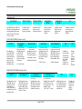
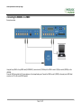
20Hz Speed Sensor with Slip Angle 20Hz Speed Sensor with Slip Angle RLVBS20SL Instruction Manual Page 1 of 27 20Hz Speed Sensor with Slip Angle Contents Introduction ............................................................................................................................................................................................................................................................. 4 Key features............................................................................................................................................................................................................................................................. 4 Standard Inventory ................................................................................................................................................................................................................................................. 5 Antenna Types and Placement .............................................................................................................................................................................................................................. 6 Antenna Separations >2M ........................................................................................................................................................................................................................ 7 GPS Antenna ............................................................................................................................................................................................................................................. 7 Using the VBS20SL as a Speed sensor ................................................................................................................................................................................................................ 8 Display Screen ........................................................................................................................................................................................................................................................ 8 Front Panel Controls............................................................................................................................................................................................................................................... 9 Slip Angle Offset ................................................................................................................................................................................................................................................... 11 Setting the Offset .................................................................................................................................................................................................................................... 11 Pitch/Roll Angle Offset ......................................................................................................................................................................................................................................... 12 Setting the Offset .................................................................................................................................................................................................................................... 12 Level ....................................................................................................................................................................................................................................................................... 12 Smoothing and Filtering ....................................................................................................................................................................................................................................... 12 Connecting the VBS20SL to a VBOX ................................................................................................................................................................................................................... 13 Configuring the VBS20SL for Use with a VBOX ................................................................................................................................................................................................. 14 Log To Compact Flash ........................................................................................................................................................................................................................... 14 Send Over Serial ..................................................................................................................................................................................................................................... 14 GPS Cold start ........................................................................................................................................................................................................................................ 14 Configuring the Digital and Analogue outputs..................................................................................................................................................................................... 15 Stand Alone Mode (Using the VBS20SL with a Datalogger other than VBOX) ................................................................................................................................................ 16 Using the CAB01 serial cable ................................................................................................................................................................................................................ 16 DIGITAL and ANALOGUE OUTPUTS ................................................................................................................................................................................................................... 17 Digital Inputs ......................................................................................................................................................................................................................................................... 18 Using the USB cable ............................................................................................................................................................................................................................... 19 Slip Angle Sensor setup in ‘Stand alone’ mode ................................................................................................................................................................................... 20 Upgrading the Firmware ....................................................................................................................................................................................................................................... 22 How to upgrade the firmware ................................................................................................................................................................................................................ 22 Connector Assignments ....................................................................................................................................................................................................................................... 23 CAN Bus Data Format ........................................................................................................................................................................................................................................... 25 Module Dimensions .............................................................................................................................................................................................................................................. 26 Fuse Reset Button ................................................................................................................................................................................................................................................ 26 Contact details ...................................................................................................................................................................................................................................................... 27 Document updates ................................................................................................................................................................................................................................................ 27 Page 2 of 27 20Hz Speed Sensor with Slip Angle EC Declaration of Conformity We declare that this product has been tested to and meet the requirements of: EC Directive 2004/104/EC “Adapting to Technical Progress Council directive 72/245/EEC relating to the radio interference (Electromagnetic Compatibility) of vehicles and amending directive 70/156/EEC on the approximation of the laws of the member states relating to the type-approval of motor vehicles and their trailers.” And has also been assessed, via Technical Construction File, by an independent DTI Competent Body and found to be in conformance with the essential requirements of: EC Directive 89/336/EEC (and amending directives) “Council Directive of 03 May 1989 on the approximation of the laws of the member states relating to electromagnetic compatibility.” DTI Competent Body responsible for issuing certificate of compliance: 3C Test Ltd, Silverstone Technology Park, Silverstone, Northants NN12 8GX Page 3 of 27 20Hz Speed Sensor with Slip Angle Introduction The VBS20SL is a multi-purpose non-contact speed sensor. Using an advanced dual antenna GPS engine, the VBS20SL can calculate not only the speed and direction of travel of the object upon which it is placed, but also an accurate Slip angle and Pitch or Roll angle. The VBS20SL also features a built-in graphic display allowing the user to set up and configure the unit without using a PC. The VBS20SL can be used in conjunction with any VBOX GPS datalogger, as well as any third-party dataloggers. Key features Non-contact 20Hz speed and distance measurement using GPS Slip Angle and Yaw Rate measurement Pitch or Roll Angle measurement 2 x 16 bit user configurable analogue outputs 2 x 24 bit digital outputs Brake / Event trigger input CAN bus interface for data output RS232 serial interface USB interface Wide 6V to 30V operating range Page 4 of 27 20Hz Speed Sensor with Slip Angle Standard Inventory Description VBS20SL 2 Way Lemo to 2 Wire Unterminated 5 Way Lemo to 9 Way ‘D’ Connector (CAN) 3 Way Lemo to Single BNC (Pin 1) USB Lead (serial Comms and upgrading) 5 Way Lemo to 5 Way Lemo (CAN Only GPS Ground Plane Antenna Dual Antenna 0.5m Magnetic Separator Dual Antenna 1m Magnetic Separator CD ROM containing VBOX software VBOX User Manual Padded Carrying Case Qty 1 1 1 2 1 1 2 1 1 1 1 1 . Page 5 of 27 Racelogic Part # VBS20SL RLCAB014 RLCAB019L RLCAB008 RLCAB042 RLCAB005-C RLVBACS103 RLVBACS055 RLVBACS062 RLVBACS030 VBTools ManA4 RLVBACS013V4 20Hz Speed Sensor with Slip Angle Antenna Types and Placement Whilst installation and use of the VBS20SL is intended to be fast and simple, careful attention must be paid to placement of the two antennas. Note: It is essential that the separation of the two antennas is exactly the same as the value set in the unit’s configuration screen. If the separation is incorrect, data may not be given or may be inaccurate. The measured distance between the antennas should be the straight-line distance between the antennas regardless of the mounting angle. It is not the 2D distance between the antennas as viewed from above. The supplied template will ensure an antenna separation of exactly 0.5m. A 1M template can also be purchased from your VBOX distributor. Antenna A is the primary antenna, from which all calculations are based. If overall slip is to be measured (at the centre of the vehicle), the primary antenna should be placed rearward of the secondary. Alignment of the antennas is not completely essential as the Slip Angle Sensor has the ability to calculate any offset. See the Slip Angle Offset Section. However if you wish to measure Pitch or Roll then the alignment of the antennas must be in o line with the vehicle or at 90 as accurately as possible. The picture above shows a typical antenna placement for the measurement of Body Slip Angle and Pitch angle. The picture to the left shows a typical antenna placement for the measurement of Body Slip Angle and Roll angle. Page 6 of 27 20Hz Speed Sensor with Slip Angle When measuring slip at a specific point on a vehicle (for example over a given wheel), the primary antenna must be placed over this point on the vehicle, whilst the secondary antenna should be placed towards the centre of the vehicle. GPS antennas require a ground plane to operate correctly. Usually, the metal roof of a vehicle performs this function. However, if a test requires an antenna to be placed off of the vehicle, then a special Ground Plane ‘mushroom-style’ antenna must replace the off-vehicle antenna, as these antennas are capable of operating without a ground plane. The Ground Plane ‘mushroom’ style antennas RLVBACS065 are available from your VBOX distributor. If only one antenna will be placed ‘off-vehicle’ then only one Ground Plane antenna need be purchased. Antenna Separations >2M When the antenna separation is >2M it is advised where possible to mount the antennas as level as possible so that the ‘LEVEL’ option can be enabled, otherwise the RTK lock is not so reliable and the Slip and Roll/Pitch data can drop out or become intermittent. The VBS20SL must only be used with the supplied antenna, unless instructed otherwise by Racelogic. GPS Antenna The GPS Antennas supplied with the VB20SL are 3.5v active antennas. For the best possible signal quality, it is important to maintain a clean connection between the antennas and the VBOX. Before fixing the antennas to the VBOX, ensure that there are no dust particles in either connector. Replacement antennas are available by contacting your VBOX distributor. The antenna is a magnetic mounting type for quick and simple mounting to the vehicle roof. For optimum GPS signal reception, make sure that the antenna is fitted to the highest point of the vehicle away from any obstructions that may block satellite reception. The GPS antenna works best with a metal ground plane underneath (eg. Vehicle roof). Please also note that when using any GPS equipment, a clear sky view is important. Objects in the surrounding area such as tall buildings or trees can block the GPS signal causing a reduction in the number of satellites being tracked, or introducing reflected signals that can decrease the accuracy of the system. NOTE: VB20SL can struggle with maintaining an RTK lock required for Slip and Pitch measurement if the antennas are placed too close to Roof Bars. If a poor mounting position cannot be avoided then use Ground plane antennas, RLVBACS065. Page 7 of 27 20Hz Speed Sensor with Slip Angle Using the VBS20SL as a Speed sensor The VBS20SL can be used as a simple speed sensor. Only Antenna A is needed if the VBS20SL is to be used as a Speed Sensor without the requirement to measure Slip, Pitch, YAW rate and Lateral Acceleration channels. For single antenna use (for standard, non-slip GPS data), the antenna should be connected to the Ant A connector. Velocity can be output on either the Analogue or Digital outputs. The VBS20SL has a brake trigger input so not only can the VBS20SL measure and output Velocity it can measure and output Trigger Velocity, Trigger to zero Time and Trigger to zero Distance. This data is available on the CAN bus along with all the other GPS data. NOTE: When measuring a braking distance the GPS optimisation must be set to High, via the Front Panel controls. And the Velocity Kalman filter set to 0 (zero). Display Screen The Display screen will display data when operating it also displays all the menus required to configure the VBS20SL via the front panel controls. On start-up, the display screen shows the unit’s firmware version and current offset value. During normal operation, the display screen displays Speed (mph or km/h) and Slip Angle, as well as the number of satellites that the VBS20SL has locked on to. There are also three status displays. OK (Green): Indicates that the VBS20SL has sufficient satellites locked with both antennas to allow normal operation. RTK (Orange): This flashes to indicate that the VBS20SL has locked onto sufficient satellites for single antenna (Speed sensor only) use. The unit will be able to give accurate data for all channels except Slip Angle, Pitch Angle, True Heading, Lateral Velocity and Yaw Rate. WAAS/40CM (Orange): Indicates the DGPS solution that is currently being utilised by the Slip Angle sensor. SATS (Yellow): This flashes to indicate that the VBS20SL has insufficient satellites on both antennas, and will not be able to operate at all. Page 8 of 27 20Hz Speed Sensor with Slip Angle Front Panel Controls The VBS20SL can be configured using the unit-mounted buttons, which enables configuration without the need for a computer. From the main screen, press the’■’ button to enter the configuration screen. Once in the configuration screen, press the ‘◄’and ‘►’ buttons to highlight the next or previous choice in any menu, and press ’■’ to select the highlighted option. Some menus contain sub-menus, for example the Analogue and Digital Output menus contain separate menus for each parameter. Main Menu UNITS MODE Press’■’ to change the displayed Velocity units. Then press ’■’ to confirm. Press’■’ to change the mode of operation between VBOX module mode and Stand Alone mode. Then press ’■’ to confirm. KMH or MPH KALMAN FILTER Press’■’ to enter the Kalman Filter Menu. In this menu the amount of filtering applied to the Velocity and Positional channels can be set between 0-4. Velocity must be set to 0 for Brake stop tests SEPARATION SWAP ANTENNAS Press’■’ and then use the ‘◄’ and ‘►’ buttons to change the antenna separation. Then press ’■’ to confirm. Set to ‘ON’ to allow the primary Antenna A to be mounted ahead of the Secondary Antenna B. Default is ‘OFF’. Then press ’■’ to confirm. Range is 0.0 – 5.0M in 0.1M increments Main Menu cont’d LEVEL Press’■’ and then use the ‘◄’ and ‘►’ buttons to enable or disable the LEVEL option. With the LEVEL set to YES the RTK lock is more resilient. But maximum ROLL or PITCH in this mode should be 10 degrees. COLDSTART Press’■’ to perform a GPS cold start SLIP OFFSET Press’■’ to enter the Slip offset sub menu. Within this sub menu the Slip offset can be calculated and applied or cleared. PITCH OFFSET DGPS MODE GPS OPTIMISATION Press’■’ to enter the Pitch offset sub menu. Within this sub menu a Pitch or Roll offset can be calculated and applied or cleared. Press’■’ and then use the ‘◄’ and ‘►’ to select a DGPS option. Press’■’ and then use the ‘◄’ and ‘►’ buttons to select one of the three Dynamic modes, High Normal or Low. Page 9 of 27 20Hz Speed Sensor with Slip Angle Main Menu cont’d SLIP SMOOTH Press’■’ and then use the ‘◄’ and ‘►’ buttons to change the amount of smoothing applied to the Slip angle channel. Then press ’■’ to confirm. 0.0 –2.0 (0.1 steps) DIGITAL1 SETUP DIGITAL2 SETUP Press’■’ to enter the setup menu for the Digital output Channel 1 Press’■’ to enter the setup menu for the Digital output Channel 2 ANALOGUE1 SETUP ANALOGUE2 SETUP Press’■’ to enter the setup menu for the Analogue output Channel 1 EXIT Press’■’ to enter the setup menu for the Analogue output Channel 1 Press’■’ to exit the setup menu and cause the settings to be saved in EEPROM DIGITAL SETUP MENU (Channel 1 and 2) OUTPUT Press’■’ and then use the ‘◄’ and ‘►’ buttons to associate either of the following channels Velocity, Slip or Pitch to the Digital output. Then press ’■’ to confirm. PULSES PER METER MAX VELOCITY MAX VALUE MAX FREQUENCY Only available when output is set to Velocity Press’■’ and then use the ‘◄’ and ‘►’ buttons to set the number of pulses per revolution. Then press ’■’ to confirm. Only available when output is set to Velocity Press’■’ and then use the ‘◄’ and ‘►’ buttons to set the maximum Velocity. Then press ’■’ to confirm. Only available when the output is set to Pitch or Slip Press’■’ and then use the ‘◄’ and ‘►’ buttons to set the maximum value of that channel. Then press ’■’ to confirm. Only available when the output is set to Pitch or Slip Press’■’ and then use the ‘◄’ and ‘►’ buttons to set the maximum Frequency used on the digital output. Then press ’■’ to confirm. 10- 400o (1o steps) 1-50Khz (0.1Khz steps) 10-400Km/h (1km/h steps) 0.1 –120 (0.1 Steps) TEST EXIT Press’■’ and then use the ‘◄’ and ‘►’ buttons to set a test value that the Digital output will simulate. Then press ’■’ to quit. Press’■’ to exit the setup menu and cause the settings to be saved in EEPROM ANALOGUE SETUP MENU (Channel1 and 2) OUTPUT Press’■’ and then use the ‘◄’ and ‘►’ buttons to associate either of the following channels Velocity, Slip or Pitch to the Analogue output. Then press ’■’ to confirm. VALUE @ +5V Press’■’ and then use the ‘◄’ and ‘►’ buttons to set the value to represent +5V. Then press ’■’ to confirm. 0-400kmh or –360o to 360o (1km/h or 0.1o steps) VALUE @ 0V VALUE @ -5V TEST Only available when output is set to Velocity Press’■’ and then use the ‘◄’ and ‘►’ buttons to set the velocity to represent 0V. Then press ’■’ to confirm. 0-400kmh (1km/h steps) Only available when the output is set to Pitch or Slip Press’■’ and then use the ‘◄’ and ‘►’ buttons to set the value to represent -5V. Then press ’■’ to confirm. –360o to 360o (0.1o steps) Press’■’ and then use the ‘◄’ and ‘►’ buttons to set a test value that the Digital output will simulate. Then press ’■’ to quit. Page 10 of 27 EXIT Press’■’ to exit the setup menu and cause the settings to be saved in EEPROM 20Hz Speed Sensor with Slip Angle Slip Angle Offset When using the VBS20SL for measurement of Slip Angle, Pitch / Roll Angle, True Heading, Lateral Velocity or Yaw Rate, it is essential that the Slip Angle offset is determined before conducting tests. This then compensates for any misalignment in the placement of the two antennas. There are also many occasions when the antennas cannot be placed directly in line with the car, such as when an ‘off-vehicle’ antenna is used to measure the Slip angle over a particular wheel. Measuring Roll angle and Slip Angle To measure Roll angle at the same time as slip angle will require the antennas to be mounted at 90 degrees to the body of the car, in this case it is vital that the offset is calculated. Setting the Offset The VBS20SL includes a built-in facility for calculating and setting the offset. With the antennas placed suitably and the antenna separation set correctly in the unit, enter the Configuration Screen and select ‘Calc. Offset’. The unit will give instructions on its display screen to allow it to determine the offset. First, the unit will instruct you to drive at a speed greater than 25km/h. Once this is achieved, the unit will tell you to drive straight, and will begin calculating the Slip Angle offset automatically. During the 5 second process, it is very important that you keep the vehicle in a straight line and above 25km/h. The Slip angle sensor beeps during this calculation and then stops beeping when it has finished calculating the offset. If required, the Slip Angle offset can be re-calculated at any time by repeating this procedure. Selecting the ‘Clear Offset’ option in the Configuration Screen will clear the current offset value. Please note that the unit will need to have a full RTK lock to perform this procedure – if the orange ‘RTK’ light is flashing, the procedure cannot be initiated. Page 11 of 27 20Hz Speed Sensor with Slip Angle Pitch/Roll Angle Offset It is not always possible to mount the antennas on a vehicle so that they are perfectly level. In order to compensate for a non-level antenna placement you should use the Pitch offset facility, which will automatically compute and then use an offset compensation. Setting the Offset Press the ’■’ button to enter the Pitch Offset menu, when the screen shows ‘CALC OFFSET’ press the ’■’ to calculate a PITCH or ROLL offset. If required, the Pitch Angle offset can be re-calculated at any time by repeating this procedure. Selecting the ‘Clear Offset’ option will also clear the current offset value. Level o The ‘LEVEL’ option should be enabled (set to YES) when the antennas are mounted within 10 of each other and the expected Pitch/Roll measurement will o not exceed 10 . With the LEVEL option enabled the GPS engines maintains its RTK lock more efficiently and the Slip and Pitch channels are less likely to drop out. o If the expected Pitch or Roll angles will be greater than 10 then the ‘LEVEL’ option should be disabled (set to ‘NO’). Note: when the antenna separation is <2M the RTK lock is very resilient in most conditions and scenarios when the ‘Level’ option is not enabled. Smoothing and Filtering Velocity: The VBS20Sl has three smoothing settings (Dynamic Modes) for velocity, High Dynamics, Normal and Low Dynamics. High dynamics has the least amount of smoothing and must be used for high dynamic tests where Time or Distance measurements are critical to the test, such as Brake stop and acceleration tests. Slip, Pitch Angle and Acceleration channels: The smoothing routine is set by selecting a value from 0 – 5.0 in 0.1 steps. This value corresponds the size in time (S) of a moving window smoothing routine. e.g. if 0.3 is selected then a smoothing window of 0.3 seconds (6 samples @20Hz) will be applied to the data. Kalman Filter: This filter provides filtering separately to the Velocity and Position channels (long, lat and height). Note with any live filter routine more latency will occur if higher levels of filtering are used. Hence the Kalman filter velocity settings should be set to zero for Brake stops and acceleration runs. Page 12 of 27 20Hz Speed Sensor with Slip Angle Connecting the VBS20SL to a VBOX Example connection Using the 5 way LEMO to 5 way LEMO cable (RLVBCAB05C), connect socket 2 (CAN Bus) of the VBOX to socket 5 (CAN) or socket 6 (SERIAL) on the VBS20SL. Power the VBOX using either the 12V cigar adapter or a fully charged battery pack. Connect the VBOX’s socket 5 (RS232) to the serial port or USB-Serial converter on a PC as for normal VBOX operation. Page 13 of 27 20Hz Speed Sensor with Slip Angle Configuring the VBS20SL for Use with a VBOX The configuration of the VBS20SL module and its individual channels is done through the connected VBOX using VBOXTools software. The VBS20SL must be set to VBOX MODULE mode via the front panel controls. When a module is connected to a VBOX, it will be automatically recognised and a tab for the module will appear in the VBOX setup ‘Channels’ section of the VBOXTools software. The VBOX creates a tabbed page in the setup window for each input module that it finds. If it finds two modules of the same type (e.g. 2 x VBS20SL) then it lists each one by its serial number on separate sub Tabs. Log To Compact Flash Placing a Tick in this column for any channel will enable a channel for logging to the compact flash card. Send Over Serial Placing a Tick in this column for any channel will include this channel in the RS232 serial data stream available at the VBOX. The bandwidth status bar at the bottom of this page gives an indication of available logging bandwidth. When the status bar is full, all of the bandwidth is used. If more logging channels are added beyond this, there is a risk that data will be lost. The bandwidth status bar is calculated for a speed optimised compact flash card. If a windows formatted card is used (see applications note ‘Compact Flash Formatting’ on the Racelogic website or the relevant section in the VBOXTools software manual), the status bar may be inaccurate with the risk that data will be lost. GPS Cold start To cold start the GPS engines in the Slip angle sensor press the button labelled Cold Start GPS. This forces the GPS engines to reset their downloaded almanac of current satellite position. This can be used if the Slip angle sensor is having trouble locking onto satellites, which can be caused by the Slip angle sensor not having been used for a period of time or if it was last used in a very different location. A GPS satellite Almanac is relevant for about 3- 4weeks, so if it has not been used or updated within that time it can cause the GPS engine struggle. After performing a GPS Cold start leave the Slip angle sensor powered up in a static situation where the antennas have a clear view of the skies, for 15 minutes. Once the Slip angle sensor has downloaded the new almanac it is much quicker to re-acquire satellites in noisy situations such as near trees buildings and bridges. Also it is much quicker to acquire satellites on power-up. Page 14 of 27 20Hz Speed Sensor with Slip Angle Configuring the Digital and Analogue outputs To adjust the configuration of the Analogue and Digital outputs of the Slip angle sensor click the Output Configure button in the Speed Sensor page of VBOXsetup. The following page will appear which allows you to select any of the channels, Velocity, Slip angle or Pitch Angle as either a Digital or Analogue output. The output range of each output is also configured on this page. Page 15 of 27 20Hz Speed Sensor with Slip Angle Stand Alone Mode (Using the VBS20SL with a Datalogger other than VBOX) The VBS20SL can also be configured for use with third-party datalogging equipment. In this mode, the unit can be configured either through the VBOX Setup screen in VBOXTools, or by using the buttons mounted on the front of the VBS20SL. Enabling Stand Alone Mode, Power up the unit and wait for it to display the standard screen (showing Speed, Slip Angle and status), then press the ’■’ button to enter the configuration menu. Use the ‘◄’and ‘►’ keys to select the option ‘Mode’, then press the’■’ button again to enter this sub-menu. Press the ‘◄’and ‘►’ buttons to change between VBOX Mode and Standalone Mode, then press the ’■’ button to select the highlighted mode. Finally, use the ‘◄’and ‘►’ buttons to move the main menu to Exit, then press the ’■’ button. The slip angle sensor will reboot to make the necessary changes. VBOX Setup To configure the VBS20SL using the VBOX Setup screen in the VBOXTools software, connect the unit to the computer via socket 6 (Serial) and a CAB01 cable, or using socket 7 (USB) and a standard USB cable. Power the unit through the 2-pin LEMO socket 1 (Power), or the 5-pin LEMO sockets 5 (CAN) or 6 (Serial). Using the CAB01 serial cable Run the VBOXTools software, if you use the CAB01 Serial cable then select the correct COM port from within the software. Page 16 of 27 20Hz Speed Sensor with Slip Angle DIGITAL and ANALOGUE OUTPUTS The digital outputs on connectors OUT1 and OUT2 are a frequency/pulse output corresponding to velocity. The pulse per meter range is adjustable in software or via the front panel controls. The analogue outputs on connectors OUT1 and OUT2 output 0-5volt DC signal corresponding to velocity. The velocity per volts range is adjustable in software or via the front panel controls. Page 17 of 27 20Hz Speed Sensor with Slip Angle Digital Inputs The DIGITAL I/O socket contains the two digital inputs for the VBS20SL. Digital input 1 is also referred to as the Brake trigger input. This input is connected to an internal timer capture module that is able to record precisely an event time for use in brake distance calculation. This period of time is called the trigger event time, and is logged as the value in milliseconds between the trigger event and the last GPS sample. Page 18 of 27 20Hz Speed Sensor with Slip Angle Using the USB cable The first time you use the USB cable, you will need to follow the instructions below. Connect the USB cable between the VBS20SL and your computer. Your computer will now recognise the presence of a new device, after a period of time a ‘Found New Hardware Wizard’ window will appear. See below. Click the option ‘No, not this time’ and click ‘Next’ A new window will appear at this window click ‘Next’ Page 19 of 27 20Hz Speed Sensor with Slip Angle A new ‘Hardware Installation’ window will appear. Click the button labelled ‘Continue Anyway’. At the last window click ‘Finish’ to complete the installation. After a short period of time a window will ask you if you wish to reboot your computer, select ‘NO’ Now disconnect the power from the VBS20SL and then reconnect the power, your computer will now recognise the Slip angle sensor. When you run the VBOXTools software it will recognise the USB connections Slip Angle Sensor setup in ‘Stand alone’ mode Run VBOX Setup from the menu bar of VBOXTools software. The VBOX Setup screen for the VBS20SL is similar to that of VBOX Dataloggers and VBOX Speed Sensors, but with only the options relevant to the VBS20SL shown. The stand-alone mode setup facility within VBOXTools is divided into four sections: CAN, GPS, Output Configure and Info. The CAN screen allows you to configure the VBS20SL’s CAN outputs. The data channels are output on seven different CAN messages, each of which can be configured individually. The options available for each message are: Message On or Off ID Value Standard or Extended ID (11 or 29bit) It is also possible to change some settings that apply to the entire CAN bus. These are: ID Format (Hexadecimal or Decimal) CAN Bus Baud Rate (1Mb/s, 500Kb/s, 250 Kb/s, 125Kb/s or Other) If you select the ‘Other’ option for baud rate, a new screen will appear in which you can enter the desired baud rate and apply advanced settings. It is not recommended that you change the advanced settings unless you are experienced with CAN protocol. The GPS screen (not shown) contains options for enabling and disabling WAAS and Local BaseStation DGPS (Differential GPS). This screen also contains a facility to send commands directly to the GPS receiver, although this should only be used when recommended by a Racelogic employee. Page 20 of 27 20Hz Speed Sensor with Slip Angle The Output Configure screen allows you to setup the unit’s analogue and digital outputs. The options for the two digital outputs are: Source (Speed, Slip, and Pitch) Maximum Value Frequency at maximum value The options for the two analogue outputs are: Source (Speed, Slip, and Pitch) Value represented by 5V Value represented by –5V (Slip or Pitch) or Value represented by 0V (Velocity) The INFO screen provides information about the VBOX hardware, including unit type, firmware version, serial number and hardware revision. This screen also shows GPS information, such as the GPS engine firmware revision, the current heading offset, the antenna separation and whether or not the antennas are swapped. Page 21 of 27 20Hz Speed Sensor with Slip Angle Upgrading the Firmware Occasionally Racelogic releases new versions of firmware code for VBOX products, this maybe to fix bugs or to add new features. New firmware for the VBS20SL is loaded into the unit using a computer and the supplied USB cable. The latest firmware upgrade (.ruf) file for the Speed Sensor is available from the Racelogic website in the VBOX downloads section. If you need the latest file, download it from the website and copy it to your computer. If you are connecting your slip angle sensor to your computer with the USB cable for the first time then follow the instructions in the Section ‘Using the USB cable‘ earlier in this manual before following the instructions below. How to upgrade the firmware Press and hold the ‘◄’ button whilst the power is connected to the Slip angle sensor. The screen will now display the UPGRADER screen, showing that it is ready for upgrading Connect the USB cable to your computer. Double click on the .ruf firmware upgrade file that you have downloaded from the website This will automatically run the upgrade program where you will see the progress of the upgrade. At the end of the process disconnect the USB and then disconnect and reconnect the power. Page 22 of 27 20Hz Speed Sensor with Slip Angle Connector Assignments Connector 1 – POWER IN (Dedicated 4.5V to 36V DC Power Connector) Pin I/O Function 1 I Power + 2 I Ground Chassis I Ground Connector 2 / 3 – OUT 1 / OUT 2 (One Analogue and One Digital Output Each) Pin I/O Function 1 O Analogue Out 1 / 2 2 O Digital Out 1 / 2 3 I Ground Chassis I Ground Connector 4 – DIG I/O (Wheel Speed and Brake Trigger Inputs) Pin I/O Function 1 I Wheel Speed 2 I NC 3 I Brake Trigger Chassis I Ground Page 23 of 27 20Hz Speed Sensor with Slip Angle Connector 5 – CAN (First CAN Bus Connector, Serial Connection to GPS Engine) Pin I/O Function 1 O RS232 Tx GPS (Tx Data from GPS engine) 2 I RS232 Rx GPS (Rx Data to GPS engine) 3 I/O CAN High (Also direct connection to Connector 6 CAN High) 4 I/O CAN Low (Also direct connection to Connector 6 CAN Low) 5 I/O Power + Chassis I Ground Connector 6 – SERIAL (Setup / Upgrade, Second CAN Bus Connector) Pin I/O Function 1 O RS232 Tx Speed Sensor (Tx Data from Speed Sensor) 2 I RS232 Rx GPS (Rx Data to Speed Sensor) 3 I/O CAN High (Also direct connection to Connector 5 CAN High) 4 I/O CAN Low (Also direct connection to Connector 5 CAN Low) 5 I/O Power + Chassis I Ground Connector 7 – USB (Setup / Upgrade) Pin I/O Function 1 2 I/O USB– 3 I/O USB+ 4 I/O Ground Chassis I Ground Connector 8 / 9 – ANT A / ANT B (GPS Antenna A / B) Pin I/O Function 1 I Signal Chassis I Ground Page 24 of 27 20Hz Speed Sensor with Slip Angle CAN Bus Data Format Format ID* 0x301 0x302 0x303 0x304 0x305 0x306 0x307 Motorola Data Bytes Update Rate 1 2 3 4 5 6 7 8 50ms (1) Sats in view (2) Time since midnight UTC (3) Position – Latitude DDMM.MMMMM 50ms (4) Position – Longitude DDMMM.MMMMM (5) Velocity. (Knots) (6) Heading (Degrees) 50ms (7) Altitude. WGS 84. (Metres) (8) Vertical velocity. (M/S) Unused (9) Status (10) Status 50ms (11) Distance. (Metres) (12) Longitudinal Accel. (G) (13) Lateral Accel. (G) 50ms (14) Distance travelled since VBOX reset (Metres) (15) Trigger time (16) Trigger Velocity (Knots) 50ms Unused (17) True Heading (Degrees) (18) Slip Angle (degrees) (19) Pitch Angle (Degrees) 50ms (20) Lateral Velocity (Knots) (21) Yaw Rate (Degrees/S) Unused Unused * Default Identifiers. The identifier values can be changed using the configuration software. (1) If Satellites in view < 3 then only Identifier 0x301 transmitted and bytes 2 to 8 are set to 0x00. (2) Time since midnight. This is a count of 10ms intervals since midnight UTC. (5383690 = 53836.90 seconds since midnight or 14 hours, 57 minutes and 16.90 seconds). (3) Position, Latitude * 100,000 (515924579 = 51 Degrees, 59.24579 Minutes North). Latitude highest bit indicates north/south hemisphere. 0=north, 1=south, Bit 7 in Status is also set. (4)Position, Longitude * 100,000 (5882246 = 0 Degrees, 58.82246 Minutes West). Longitude highest bit indicates east/west of Greenwich meridian. 0=west,1=east. Bit 6 in Status is also set. (5) Velocity, 0.01 knots per bit. (6) Heading, 0.01 per bit. (7) Altitude, 0.01 meters per bit, signed. (8) Vertical Velocity, 0.01 m/s per bit, signed. (9) Status. 8 bit unsigned char. Bit 0=VBOX Lite, Bit 1=Open or Closed CAN Bus (1=open), 2=VBOX3. (10) Status is an 8 bit unsigned char. Bit 0 is always set, Bit 3=brake test started, Bit 4 = Brake trigger active, Bit 5 = DGPS active. (11) Distance, 0.000078125 meters per bit, unsigned. (12) Longitudinal Acceleration, 0.01G per bit, signed. (13) Lateral Acceleration, 0.01G per bit, signed. (14) Distance travelled in meters since VBOX reset. (15) Time from Trigger event to Zero Km/h. The VBOX CAN database is available in Vector Database (DBC File) format (16) Velocity at brake trigger point in Knots. from the Racelogic VBOX website. (17) True Heading of vehicle, 16-bit signed integer * 100. (18) Slip Angle, 16-bit signed integer * 100. (19) Pitch Angle, 16-bit signed integer * 100. (20) Lateral Velocity, 16-bit signed integer * 100. (21) Yaw Rate, 16-bit signed integer * 100. Page 25 of 27 20Hz Speed Sensor with Slip Angle Module Dimensions Fuse Reset Button The VBS20SL contains a fuse to protect it from excessive currents. If the unit is accidentally subjected to large currents and the fuse has become tripped, it can be reset by pressing the button marked ‘Fuse Reset’ all the way into the unit with a long, thin implement. Page 26 of 27 20Hz Speed Sensor with Slip Angle Contact details Racelogic Ltd Unit 10 Swan Business Centre Osier Way Buckingham MK18 1TB England Tel +44 (1280) 823803 Fax +44 (1280) 823595 Email [email protected] Web www.racelogic.co.uk Document updates Revision 1 2 3 4 5 6 7 8 9 Description First Release. JDH Small text corrections. KB Correction to power supply voltage requirements. JDH Inclusion of Declaration of Conformity Statement. CAS Amendment to manual in accordance with latest firmware v1.01build194 Correction to smoothing definitions Addition of Format: Motorola to CAN Bus Data Format table Update of Address Update inventory, images and general content. LN Page 27 of 27 Date 21/04/06 04/07/06 18/12/06 05/06/07 27/06/07 18/08/07 03/12/07 30/04/08 19/01/12