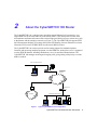
1
CyberSWITCH 100 FAMILY INFORMATION PWR LAN LINE CH1 CH2 NT1 P/N 9031944-01 September 1997 Notice Cabletron Systems reserves the right to make changes in specifications and other information contained in this document without prior notice. The reader should in all cases consult Cabletron Systems to determine whether any such changes have been made. The hardware, firmware, or software described in this manual is subject to change without notice. IN NO EVENT SHALL CABLETRON SYSTEMS BE LIABLE FOR ANY INCIDENTAL, INDIRECT, SPECIAL, OR CONSEQUENTIAL DAMAGES WHATSOEVER (INCLUDING BUT NOT LIMITED TO LOST PROFITS) ARISING OUT OF OR RELATED TO THIS MANUAL OR THE INFORMATION CONTAINED IN IT, EVEN IF CABLETRON SYSTEMS HAS BEEN ADVISED OF, KNOWN, OR SHOULD HAVE KNOWN, THE POSSIBILITY OF SUCH DAMAGES. Copyright September 1997, by Cabletron Systems, Inc., P.O. Box 5005, Rochester, NH 03866-5005 All Rights Reserved Printed in the United States of America Part Number: 9031944-01 CyberSWITCH and QuickSET are registered trademarks of Cabletron Systems, Inc. All other product names mentioned in this manual may be trademarks or registered trademarks of their respective companies. FCC Notice Note: This equipment has been tested and found to comply with the limits for a Class B digital device, pursuant to Part 15 of the FCC Rules. These limits are designed to provide reasonable protection against harmful interference in a residential installation. This equipment generates, uses, and can radiate radio frequency energy and, if not installed and used in accordance with the instructions, may cause harmful interference to radio communications. However, there is no guarantee that interference will not occur in a particular installation. If this equipment does cause harmful interference to radio or television reception, which can be determined by turning the equipment off and on, the user is encouraged to try to correct the interference by one or more of the following measures: Reorient or relocate the receiving antenna. Increase the separation between the equipment and receiver. Connect the equipment into an outlet on a circuit different from that to which the receiver is connected. Consult the dealer or an experienced radio/TV technician for help. WARNING: Changes or modifications made to this device which are not expressly approved by the party responsible for compliance could void the user’s authority to operate the equipment. DOC Notice This product conforms with Canadian Class B emissions regulations. Ce produit se conforme aux réglements d’émision Canadienne classe B. CyberSWITCH 100 Advanced User Information i Notice VCCI Notice ii CyberSWITCH 100 Advanced User Information Notice VCCI Notice This is a Class A product based on the standard of the Voluntary Control Council for Interference by Information Technology Equipment (VCCI). If this equipment is used in a domestic environment, radio disturbance may arise. When such trouble occurs, the user may be required to take corrective actions. Cabletron Systems, Inc. Program License Agreement IMPORTANT: Before utilizing this product, carefully read this License Agreement. This document is an agreement between you, the end user, and Cabletron Systems, Inc. (“Cabletron”) that sets forth your rights and obligations with respect to the Cabletron software program (the “Program”) contained in this package. The Program may be contained in firmware, chips or other media. BY UTILIZING THE ENCLOSED PRODUCT, YOU ARE AGREEING TO BECOME BOUND BY THE TERMS OF THIS AGREEMENT, WHICH INCLUDES THE LICENSE AND THE LIMITATION OF WARRANTY AND DISCLAIMER OF LIABILITY. IF YOU DO NOT AGREE TO THE TERMS OF THIS AGREEMENT, PROMPTLY RETURN THE UNUSED PRODUCT TO THE PLACE OF PURCHASE FOR A FULL REFUND. Cabletron Software Program License 1. LICENSE. You have the right to use only the one (1) copy of the Program provided in this package subject to the terms and conditions of this License Agreement. You may not copy, reproduce or transmit any part of the Program except as permitted by the Copyright Act of the United States or as authorized in writing by Cabletron. 2. OTHER RESTRICTIONS. You may not reverse engineer, decompile, or disassemble the Program. 3. APPLICABLE LAW. This License Agreement shall be interpreted and governed under the laws and in the state and federal courts of New Hampshire. You accept the personal jurisdiction and venue of the New Hampshire courts. CyberSWITCH 100 Advanced User Information iii Notice Exclusion of Warranty and Disclaimer of Liability 1. EXCLUSION OF WARRANTY. Except as may be specifically provided by Cabletron in writing, Cabletron makes no warranty, expressed or implied, concerning the Program (including its documentation and media). CABLETRON DISCLAIMS ALL WARRANTIES, OTHER THAN THOSE SUPPLIED TO YOU BY CABLETRON IN WRITING, EITHER EXPRESSED OR IMPLIED, INCLUDING BUT NOT LIMITED TO IMPLIED WARRANTIES OF MERCHANTABILITY AND FITNESS FOR A PARTICULAR PURPOSE, WITH RESPECT TO THE PROGRAM, THE ACCOMPANYING WRITTEN MATERIALS, AND ANY ACCOMPANYING HARDWARE. 2. NO LIABILITY FOR CONSEQUENTIAL DAMAGES. IN NO EVENT SHALL CABLETRON OR ITS SUPPLIERS BE LIABLE FOR ANY DAMAGES WHATSOEVER (INCLUDING, WITHOUT LIMITATION, DAMAGES FOR LOSS OF BUSINESS, PROFITS, BUSINESS INTERRUPTION, LOSS OF BUSINESS INFORMATION, SPECIAL, INCIDENTAL, CONSEQUENTIAL, OR RELIANCE DAMAGES, OR OTHER LOSS) ARISING OUT OF THE USE OR INABILITY TO USE THIS CABLETRON PRODUCT, EVEN IF CABLETRON HAS BEEN ADVISED OF THE POSSIBILITY OF SUCH DAMAGES. BECAUSE SOME STATES DO NOT ALLOW THE EXCLUSION OR LIMITATION OF LIABILITY FOR CONSEQUENTIAL OR INCIDENTAL DAMAGES, OR ON THE DURATION OR LIMITATION OF IMPLIED WARRANTIES, IN SOME INSTANCES THE ABOVE LIMITATIONS AND EXCLUSIONS MAY NOT APPLY TO YOU. United States Government Restricted Rights The enclosed product (a) was developed solely at private expense; (b) contains “restricted computer software” submitted with restricted rights in accordance with Section 52227-19 (a) through (d) of the Commercial Computer Software - Restricted Rights Clause and its successors, and (c) in all respects is proprietary data belonging to Cabletron and/or its suppliers. For Department of Defense units, the product is licensed with “Restricted Rights” as defined in the DoD Supplement to the Federal Acquisition Regulations, Section 52.227-7013 (c) (1) (ii) and its successors, and use, duplication, disclosure by the Government is subject to restrictions as set forth in subparagraph (c) (1) (ii) of the Rights in Technical Data and Computer Software clause at 252.227-7013. Cabletron Systems, Inc., 35 Industrial Way, Rochester, New Hampshire 03867-0505. Instructions for Trained Service Personnel Only CAUTION: Danger of explosion if battery is incorrectly placed. Replace only with the same or equivalent type recommended by the manufacturer. Dispose of used batteries according to the manufacturer’s instructions. Approvals Safety: EN 60950, UL 1950, CSA 22.2 No. 950 Emissions: EN 55022/CISPR22 Class B, VCCI Class 2, FCC Part 15 Class B iv CyberSWITCH 100 Advanced User Information Contents PREFACE .....................................................................................................................................VII ISDN Overview ..............................................................................................vii How to Use This Guide ..................................................................................vii Document Conventions.................................................................................viii Getting Help ................................................................................................... ix CHAPTER 1 ISDN LINE ORDERING AND CONFIGURATION ................................................ 1 Arranging ISDN Service .................................................................................. 1 Telephone Switch Support .............................................................................. 2 ISDN BRI Line Configuration .......................................................................... 2 ISDN BRI Configurations.......................................................................... 3 SPIDs, Directory Numbers and Telephone Numbers............................... 4 Telephone Switch Parameters ........................................................................ 5 CHAPTER 2 ABOUT THE CYBERSWITCH 100 ROUTER....................................................... 9 CyberSWITCH 100 Hardware....................................................................... 10 ISDN WAN Connection .......................................................................... 10 POTS Analog Telephone Connection .................................................... 10 CyberSWITCH 100 Software Support .......................................................... 10 IEEE 802.3 Ethernet............................................................................... 11 Point-to-Point Protocol (PPP) ................................................................. 11 PAP and CHAP Security ........................................................................ 11 ISDN ....................................................................................................... 12 Telephone Switch Support ..................................................................... 12 Bridging and Routing .............................................................................. 13 IP and IPX Routing ....................................................................................... 14 Network Information Diagrams ............................................................... 14 Bridging and Routing Protocol Filtering .................................................. 20 Bandwidth Optimization Features........................................................... 20 POTS Analog Line Interface................................................................... 21 Simple Network Management Protocol (SNMP) .................................... 21 Software Upgrades................................................................................. 21 CyberSWITCH 100 Advanced User Information v Contents CHAPTER 3 PLANNING YOUR ROUTER’S CONFIGURATION ............................................ 23 Configuration Process and Terminology ....................................................... 23 Custom Step-by-Step Configuration ............................................................. 23 Collect Network Information ................................................................... 23 Remote Connections .............................................................................. 31 CHAPTER 4 CYBERSWITCH 100 HARDWARE FEATURES ................................................ 39 Front Panel.................................................................................................... 39 Rear Panel .................................................................................................... 41 Port Descriptions........................................................................................... 42 Configuration Switches ................................................................................. 44 CHAPTER 5 TROUBLESHOOTING ........................................................................................ 47 Investigating Hardware Installation Problems ............................................... 47 Investigating Software Configuration Problems ............................................ 48 How to Obtain Technical Support ................................................................. 50 Getting Help .................................................................................................. 51 APPENDIX A HARDWARE SPECIFICATIONS ........................................................................ 53 APPENDIX B GLOSSARY ........................................................................................................ 55 vi CyberSWITCH 100 Advanced User Information Preface Welcome to the Cabletron Systems CyberSWITCH 100 Family Advanced User Information Guide. This guide provides hardware specifications for the CyberSWITCH 100 family of products that includes the CSX101, CSX103, CSX104, and CSX105. This guide also provides background information about the INtegrated Services Digitak Network (ISDN) including a step-by-step guide for ordering ISDN from your service provider, and bridging and routing information. ISDN Overview ISDN provides an inexpensive switched digital access to remote sites. The ISDN BRI standard provides for two high speed 64 K bits per seconds (Kbps) bearer channels used for voice or data connections and one 16 Kbps signaling data (D) channel used for call setup, signaling and other information. ISDN allows all types of information to be transmitted including voice, data, fax and video. Multiple devices can be linked to a single ISDN connection, each having its own telephone number. Two or more channels can be combined into a single larger transmission pipe offering variable transmission speeds. How to Use This Guide Below is a list of the chapters comprising this guide, with brief explanations of their content: Chapter 1, ISDN Line Ordering and Configuration, provides the information you need to order ISDN service from the telephone company. Chapter 2, About the CyberSWITCH 100 Router, describes the CSX100 family hardware components and software protocols and features. Chapter 3, Planning Your Router’s Configuration, describes the router configuration process. Chapter 4, CyberSWITCH 100 Hardware Features, describes the front and rear panels of the CyberSWITCH 100. Chapter 5, Troubleshooting, provides detailed troubleshooting help. Appendix A, Hardware Specifications, provides the hardware specifications for the CSX100. Apppendix B, Glossary, defines commonly used terms, and is located at the back of this guide. CyberSWITCH 100 Advanced User Information vii Preface Document Conventions The following conventions are used throughout this guide: NOTE Note symbol. Calls the reader’s attention to any item of information that may be of special importance. Tip symbol. Conveys helpful hints concerning procedures or actions. TIP ! Caution symbol. Contains information essential to avoid damage to the equipment. CAUTION Warning symbol. Warns against an action that could result in equipment damage, personal injury or death. viii CyberSWITCH 100 Advanced User Information Preface Getting Help If you need additional support related to this device, or if you have any questions, comments, or suggestions concerning this manual, contact Cabletron Systems Global Call Center: Phone (603) 332-9400 Internet mail [email protected] FTP Login Password ctron.com (134.141.197.25) anonymous your email address Modem setting (603) 335-3358 8N1: 8 data bits, No parity, 1 stop bit BBS For additional information about Cabletron Systems or our products, visit our World Wide Web site: http://www.cabletron.com/ For technical support, select Service and Support. Before calling Cabletron Systems Global Call Center, have the following information ready: • Your Cabletron Systems service contract number • A description of the failure • A description of any action(s) already taken to resolve the problem (e.g., changing mode switches, rebooting the unit, etc.) • The serial and revision numbers of all involved Cabletron Systems products in the network • A description of your network environment (layout, cable type, etc.) • Network load and frame size at the time of trouble (if known) • The device history (i.e., have you returned the device before, is this a recurring problem, etc.) • Any previous Return Material Authorization (RMA) numbers CyberSWITCH 100 Advanced User Information ix Preface x CyberSWITCH 100 Advanced User Information 1 ISDN Line Ordering and Configuration This chapter provides ISDN BRI (Basic Rate Interface) line ordering and configuration information. It contains the following sections: • Arranging ISDN Service • Telephone Switch Support • ISDN BRI Line Configuration • SPIDs, Directory Numbers and Telephone Numbers • Telephone Switch Parameters Read the first section in this chapter for an overview of the steps required to order ISDN service from your service provider (telephone company). The rest of the chapter details the information that the service provider needs to give you, and which you need to give to the service provider. Arranging ISDN Service The service provider requires certain information about the capabilities of the CyberSWITCH 100. You must give the service provider the required switch settings (parameters) for the provider’s central office switch. Consult with your service provider at least two months before you require the installation and use of the ISDN service. Complete the following steps to arrange your ISDN service: 1. Contact the service provider and determine what type of ISDN central office switches are available (see Telephone Switch Support in this chapter). 2. Supply the service provider with the provisioning information for their switch type to enable proper configuration of the ISDN line (see Telephone Switch Parameters in this chapter). 3. Once the ISDN line is installed, ensure that the service provider supplies you with the following information: • ISDN telephone numbers • ISDN Service Profile Identifier numbers (SPIDs) and/or Directory Numbers (DNs) (see SPIDs, Directory Numbers and Telephone Numbers in this chapter) CyberSWITCH 100 Advanced User Information 1 ISDN Line Ordering and Configuration Telephone Switch Support Your telephone company may offer a variety of ISDN switch types. You must contact your service provider and find out which type of ISDN service is available. The following switch types are currently supported by the CyberSWITCH 100 within the U.S.: • National ISDN 1 (NI-1) • AT&T 5ESS w/Custom Software • DMS-100 Outside of the U.S. the following switch types are currently supported: • NET3 (European ISDN) • NET3SW (European Swiss-variant) • NTT (Nippon Telegraph and Telephone) • KDD (Kokusai Denshin Denwa Co., Ltd.) • French Delta (VN4) switches ISDN BRI Line Configuration You need to order one Basic Rate Interface (BRI) ISDN line from your service provider. The Basic Rate Interface ISDN line provides two full duplex 64 (Kbps) B channels used for voice, data, fax, etc. and one full duplex 16 Kbps channel used for signaling. Each B channel can be used for a call; i.e., two calls can occur at the same time. Services vary from individual service providers. NOTE Full 64 Kbps for each channel (referred to as “clear channel”) may not be available across the entire communications link. Today, many providers still use in-band signaling (the 8 Kbps signaling is taken from the B channel bandwidth) so that you may only achieve a 56 Kbps channel speed. The service provider requires some information from you about your configuration. You must provide your service provider with the required switch settings for the provider’s telephone switch (see Telephone Switch Parameters in this chapter). Consult with your service provider at least two months before requiring the installation and use of the ISDN service. 2 CyberSWITCH 100 Advanced User Information ISDN Line Ordering and Configuration In the U.S. and Canada, an NT1 Network Terminator is required to provide an interface between the CyberSWITCH 100 and the ISDN line. The NT1 offers conversion between the two-wire twisted pair (U-loop interface) used by telephone companies and the four-wire terminal equipment (S/T Interface) as well as line-testing capabilities. You can order the CyberSWITCH 100 with an internal NT1 (CSX103 or CSX105) or use your own NT1 equipment (CSX101, and CSX104). External Network Terminator equipment comes with its own power supply (built-in or external). In Europe and Japan, the telephone company provides the NT1 and offers end-users the S/T interface. The S refers to a connection between customer equipment in some ISDN configurations when a PBX is present. The T refers to the connection between the NT1 device and the CyberSWITCH 100. The ISDN pairs are the same wires that exist for analog telephone service. In most cases, the same wires can be used for the ISDN line. The EIA/TIA standard for wiring is Unshielded Twisted Pair (UTP) cable. Category 3 or above, 24 AWG (American Wire Gauge). The standard also recommends using 8-contact RJ45 jacks for new ISDN service installation. No special conditioning is required; in some cases, conditioning must be removed. ISDN BRI Configurations ISDN BRI lines can be configured in point-to-point and multi-point configurations. With a point-to-point configuration, only one device is connected to the ISDN line. With a multi-point configuration, it is possible to have up to 8 devices (telephones, faxes, routers, etc.) connected to the line. Since the ISDN BRI line is used for a high speed LAN-to-LAN link, you must ensure that additional devices connected to the S/T interface allow sufficient access for the bandwidth requirements of the CyberSWITCH 100. The device support through the POTS (Plain Old Telephone Service) interface allows multiple devices per port, but only one call initiated at a time (though another call can be in progress). CyberSWITCH 100 Advanced User Information 3 ISDN Line Ordering and Configuration SPIDs, Directory Numbers and Telephone Numbers The service provider gives you up to three sets of numbers for identifying the ISDN line and devices. You may be assigned none, one, or two Service Profile Identifier numbers (SPIDs) or Directory Numbers (DNs) depending on the service provider and country. Directory Numbers A Directory Number (DN) is the phone number of your ISDN line, assigned by your telephone company. Some digital central office switches (AT&T 5ESS Custom) require only a single DN Number for your CSX100. Others, like the AT&T 5ESS with the NT1 service, or the Northern Telecom DMS-100 with the NT1 service, require a separate number for each B channel. Service Profile Identifiers SPIDs, also assigned by the ISDN service provider, identify the services and features that the telephone company switch provides for your ISDN line. Commonly implemented in the U.S. and Canada, the SPID is often derived from the directory number, combined in a series with other digits. SPIDs are not generally implemented outside the U.S. and Canada. 4 CyberSWITCH 100 Advanced User Information ISDN Line Ordering and Configuration Telephone Switch Parameters Once you have contacted your service provider and learned the type of ISDN switch being used, refer to Tables 1 through 3. You must supply the appropriate provisioning information to the service provider to ensure proper configuration of the ISDN line. NOTE National ISDN (NI-1) is a specification released by Bellcore outlining a basic set of ISDN services for standardization by equipment vendors. Table 1 National ISDN 1 (NI-1) Parameters ISDN Switch Parameters Value B1 Circuit Switched Data & Voice B2 Circuit Switched Data & Voice D Signaling Only Multipoint Yes Terminal Type A Display Off TEI Dynamic MTERM 1 MAXB CHL 2 ACT USR Y CSD 2 CSD CHL Any CSD Limit 2 CA Pref 1 EKTS No Nail Up None CyberSWITCH 100 Advanced User Information 5 ISDN Line Ordering and Configuration Table 2 6 AT&T 5ESS with Custom Software ISDN Switch Parameters Value B1 Circuit Switched Data & Voice B2 Circuit Switched Data & Voice D Signaling Only Multipoint No Terminal Type A Display Off TEI Dynamic MTERM 1 MAXB CHL 2 ACT USR Y CSD 2 CSD CHL Any CSD Limit 2 CA Pref 1 Nail Up None CyberSWITCH 100 Advanced User Information ISDN Line Ordering and Configuration Table 3 Northern Telecom DMS-100 ISDN Switch Parameters Value B1 Circuit Switched Data & Voice B2 Circuit Switched Data & Voice D Signaling Only EKTS No Ringing Indicator No Release Key No PVER 01 TEI Dynamic MAXKEYS 64 Nail Up None CyberSWITCH 100 Advanced User Information 7 ISDN Line Ordering and Configuration 8 CyberSWITCH 100 Advanced User Information 2 About the CyberSWITCH 100 Router The CyberSWITCH 100 is a bridge/router providing remote Ethernet LAN connectivity via a single ISDN line for the small office or home office (SOHO). This multi-protocol router offers telecommuters and home and remote office workers high speed dial-up access to remote sites, such as the Internet and the enterprise network (see Figure 1). The CyberSWITCH 100 supports IEEE 802.1D transparent bridging, IP routing, and Netware IPX Routing, between Ethernet Local Area Networks (LANs) across an ISDN Wide Area Network (WAN) resource. The CyberSWITCH 100 can also provide two-line analog support for standard telephone, facsimile, and answering machine equipment, over the ISDN line. Analog line service is supported over the ISDN B channels, affording simultaneous voice, fax and data communications. The CyberSWITCH 100 manages incoming and outgoing calls, giving analog calls priority over data traffic as needed. SMALL OFFICE/HOME OFFICE CyberSWITCH 100 ISDN NETWORK 2 B CHANNELS 64000 BPS PC/CLIENT ISP ENTERPRISE CENTRAL OFFICE 100_01 INTERNET CyberSWITCH 100 Figure 1 Typical CyberSWITCH 100 Configuration CyberSWITCH 100 Advanced User Information 9 About the CyberSWITCH 100 Router CyberSWITCH 100 Hardware The CyberSWITCH 100 family (consisting of the CSX101, CSX103, CSX104, and CSX105) provides one Ethernet port and one ISDN Basic Rate Interface (BRI) port (with built-in S/T, or U interfaces). The CSX104 and CSX105 also support two analog device Plain Old Telephone Service (POTS) ports. All models incorporate a built-in power supply. The CyberSWITCH 100 provides 10 Mbps Ethernet/IEEE 802.3 support through an 8-pin RJ45 10BASE-T jack on the rear of the unit. The device supports an unlimited number of LAN users. ISDN WAN Connection The CyberSWITCH 100 provides one ISDN BRI port. ISDN allows fast dial setup and tear down with high-speed data transfer rates. ISDN connectivity is through an 8-pin RJ45 S/T jack or U jack on the rear of the unit. POTS Analog Telephone Connection The CSX104 and CSX105 provide two standard POTS (Plain Old Telephone Service) analog device ports for connecting telephone, facsimile and analog modem equipment. Each port can be used to connect multiple devices. The maximum length for each analog line is 100 feet (30 meters). CyberSWITCH 100 Software Support The CyberSWITCH 100 supports IEEE 802.1d bridging, TCP/IP routing, and IPX Routing as an option. Wide Area Networking includes synchronous Point -to-Point Protocol in Single Link or Multi-Link Protocol mode. Remote access is via ISDN Basic Rate Interface (BRI). Enhanced bandwidth management techniques are employed to optimize data throughput and minimize connect-time across dial-up WAN resources. Security features, including Pap and CHAP authentication, are used to prevent unauthorized access to the network and data resources. The software supports emulation of central office services to allow calls from/to analog devices on each of the POTS interface ports. These lines support connection to local analog devices, Call Progress tones, and DTMF. This device supports industry-standard protocols, security features, compression algorithms and network management tools to ensure interoperability with equipment from other vendors. 10 CyberSWITCH 100 Advanced User Information About the CyberSWITCH 100 Router IEEE 802.3 Ethernet The router provides a standard 802.3 Media Access Control (MAC) layer for CSMA/CD Ethernet communications. All bridging and routing protocols are supported across the Ethernet link. Point-to-Point Protocol (PPP) PPP is a data link layer industry standard WAN protocol for transferring multi-protocol data traffic over point-to-point connections. It is suitable for both high-speed synchronous ports as well as lower speed asynchronous dial-up ports. With this protocol, options such as security and network protocols can be negotiated over the connection. This device supports synchronous PPP over the ISDN port. In Single Link Mode, PPP uses one ISDN B channel for data transmission. PPP runs over each ISDN B channel for two separate conversations (split B-channel). In Multi-Link Protocol Mode, PPP simultaneously sends and receives data over two ISDN B-channels on the same connection to optimize bandwidth usage. The STAC Electronics Stacker LZS Compression Protocol is supported over PPP providing up to 4:1 data compression. PAP and CHAP Security The CyberSWITCH 100 supports the Password Authentication Protocol (PAP) and Challenge Handshake Authentication Protocol (CHAP) under PPP. PAP provides verification of passwords between routers using a 2-way handshake. One router (peer) sends its system name and password to the other router. Then the other router (known as the authenticator) checks the peer’s password against the configured remote router’s password and returns acknowledgment. CHAP is more secure than PAP as unencrypted passwords are not sent across the network. CHAP uses a 3-way handshake. One router (known as the authenticator) challenges the other router (known as the peer) by generating a random number and sending it along with the system name. The peer then applies a one-way hash algorithm to the random number and returns this encrypted information along with the system name. The authenticator then runs the same algorithm and compares the result with the expected value. This authentication method depends upon a password or secret, known only to both ends. CyberSWITCH 100 Advanced User Information 11 About the CyberSWITCH 100 Router ISDN ISDN provides switched digital access to remote sites. The ISDN BRI standard provides for two high speed 64 Kbps bearer (B) channels used for voice or data connections and one 16 Kbps signaling data (D) channel used for call setup, signaling and other information. ISDN allows all types of information to be transmitted including voice, data, fax, and video. Multiple devices can be linked to a single ISDN connection, each having their own telephone number. Two or more channels can be combined into a single larger transmission pipe offering variable transmission speeds. The CyberSWITCH 100 supports one ISDN BRI line and either or both of the B channels for transferring data. Voice is transferred using either B channel. If the two B channels are used for separate connections, each provides up to 64 Kbps transfer rates. Both channels can be used together to provide uncompressed data transfer at up to 128 Kbps. The CyberSWITCH 100 can also transfer compressed data at up to 512 Kbps (data rate, after decompression). A Network Terminator device (NT1) provides the interface between ISDN terminal (router) equipment and the ISDN service provider. In the U.S., the NT1 is provided by the customer; outside the U.S., the NT1 is provided by the ISDN service provider. Telephone Switch Support The following telephone switch types are supported within the U.S.: • National ISDN (NI-1) • AT&T 5ESS w/Custom Software • DMS-100 Outside of the U.S. the following switch types are supported: • NET3 (European ISDN) • NET3SW (European Swiss-variant) • NTT (Nippon Telegraph and Telephone) • KDD (Kokusai Denshin Denwa Co., Ltd.) • French Delta (VN4) switches 12 CyberSWITCH 100 Advanced User Information About the CyberSWITCH 100 Router Bridging and Routing Bridging — Bridging connects two or more LANs together so that all devices share the same logical LAN segment and network number. The bridge examines a portion of each network frame called the header. This header contains control information for the frame. The bridge compares the destination address of the frame with the address from which the frame was received. If the address indicates that the sending station and the destination station are on the same side of the bridge, the frame is discarded. If the addresses indicate that the sending station and the receiving station are not on the same side, then the bridge forwards the frame to its other interface. During this process, the bridge formulates a table that allows it to identify which stations are connected to which LAN segment. The destination addresses of received frames are compared to this address table and decisions are made to discard, or forward frames, based on the outcome. Transparent bridging allows locally connected devices to send frames to all devices as if they are locally connected. Bridging allows frames to be sent to all destinations regardless of the network protocols used. It allows protocols that cannot be routed (such as NETBIOS) to be forwarded and optimizes internetwork capacity by localizing traffic on LAN segments. A bridge extends the physical reach of networks beyond the limits of each LAN segment. Filters are used to increase network security in bridged networks. Routing — Routing provides a way to transfer data from source to destination over different LAN and WAN links using one or more network protocol formats. Routing relies on routing address tables to determine the best path for each packet. Routing tables can be seeded; i.e., addresses for remote destinations are placed in the table along with network address masks and a metric for path latency. Routing tables are also built dynamically; i.e., the location of remote stations, hosts, and networks, are updated from broadcast packet information. Routing helps to increase network capacity by localizing traffic on LAN segments and reducing the number of broadcasts that would result from bridged traffic. Routing also provides security by isolating traffic on segmented LANs. Routing extends the reach of networks beyond the limits of each LAN segment. CyberSWITCH 100 Bridging and Routing — The CyberSWITCH 100 can operate as a bridge, as a router, or as both (sometimes called a brouter). The CyberSWITCH 100 operates as a router for network protocols that are supported when routing is enabled. The router operates as a bridge when bridging is enabled. When both bridging and routing are enabled, routing takes precedence over bridging; i.e., the router uses the protocol address information of the packet to route the packet to the correct destination and if the protocol is not supported, the router uses the MAC address information to bridge the packet. CyberSWITCH 100 Advanced User Information 13 About the CyberSWITCH 100 Router Operation of the CyberSWITCH 100 is influenced by routing and bridging controls and filters set during router configuration as well as automatic spoofing and filtering performed by the CyberSWITCH 100. General IP routing, and routing or bridging from specific remote routers are controls set during the configuration process. Spoofing and filtering, which minimize the number of packets across the WAN, are performed automatically by the CyberSWITCH 100. For example, RIP routing packets and certain NetBEUI packets are spoofed even if only bridging is enabled. IEEE 802.1d Bridging — The CyberSWITCH 100 supports the IEEE 802.1d standard for LAN to LAN bridging. Bridging is provided over PPP as well as adjacent LAN ports. The bridging software uses transparent bridging. Configured as a bridge, the unit bridges data packets to the destination, regardless of the network protocols used. Also included is the Spanning Tree Protocol allowing the CyberSWITCH 100 to provide bridging redundancy while preventing data loops and duplicate data. This is a learning bridge; i.e., the bridge builds and updates an address table with each MAC source address and associated information when the packets are received. IP and IPX Routing IP Routing — IP rrouting support provides the ability to process TCP/IP frames at the network layer for routing. IP routing support includes the Routing Information Protocol (RIP) that allows the exchange of routing information on a TCP/IP network. The router receives and broadcasts RIP messages to adjacent routers and workstations. Since IP sends out periodic RIP frames that could keep dial-up links permanently connected, filtering and spoofing are performed to minimize these broadcasts on the WAN links. The router filters service packets on one end and emulates them at the other end with spoofing. The router uses the “piggyback method” to send RIP update packets to the WAN port. The piggyback method means that RIP update packets are sent only when the dial-up link is established because of data traffic. Network Information Diagrams It is helpful to draw a diagram (see Figure 2 on the following page) including all locations, addresses, router names, etc. This section includes sample diagrams needed to configure the CyberSWITCH 100. You may need different addressing information depending on whether you are configuring IP routing and/or NetWare IPX routing. TCP/IP Route Addresses — If the CyberSWITCH 100 is to direct IP traffic over the ISDN connection, the routing table in the CyberSWITCH 100 must be “seeded” with static IP routes so that it dials out to the appropriate remote router when IP traffic is targeted to networks and stations 14 CyberSWITCH 100 Advanced User Information About the CyberSWITCH 100 Router beyond that remote router. An IP route includes an IP address, subnet mask and metric. The metric is a number representing the perceived cost in reaching the remote network or station. After the link is established, RIP update packets are dynamically added to the routing table. Seeding the routing table is not necessary when the CyberSWITCH 100 never dials out; it discovers remote networks and stations beyond the calling router as soon as RIP updates arrive (provided the remote router supports RIP and RIP packets are allowed to flow on the WAN link). TCP/IP Default Route — One default route can be designated in the routing table for all traffic that cannot be directed to other specific routes. The default route is specified as 0.0.0.0 255.255.255.255. There can be only one default route specified for all the remote database entries. NETWORK INFORMATION LAYOUT ETHERNET LAN IP ADDRESS SUBNET MASK GATEWAY PC CyberSWITCH 100 SYSTEM NAME MESSAGE PAP/CHAP PASSWORD CyberSWITCH 100 WAN IP ADDRESS SUBNET MASK (IF REQUIRED) ISDN LINE SWITCH TYPE SPIDs, DNs ISDN REMOTE ROUTER WAN IP ADDRESS SUBNET MASK (IF REQUIRED) REMOTE ISDN PHONE NUMBERS REMOTE LAN NETWORK IP ADDRESSES SUBNET MASKS METRICS REMOTE ROUTER 100_10 ROUTER NAME PAP/CHAP PASSWORD NETWORK AND STATIONS BEYOND THE REMOTE ROUTER Figure 2 Network Information Diagram CyberSWITCH 100 Advanced User Information 15 About the CyberSWITCH 100 Router Local and Remote WAN IP Addresses — You may need to specify a Local WAN IP address and/or a Remote WAN IP address for the WAN connection to the remote router depending on IP address negotiation under PPP. Check with your system administrator for details on whether the router must communicate in numbered or unnumbered mode and what addresses are required. In unnumbered mode, neither IP address is defined on the link. In numbered mode, one IP address is defined on each end of the WAN link. The CyberSWITCH 100 automatically determines whether to run in unnumbered mode or numbered mode. If unnumbered mode negotiation fails, numbered mode is attempted using the Ethernet LAN IP address as a default. If you have specified a Local WAN IP address, unnumbered mode negotiation is not performed; i.e., the operating mode is numbered. If a Local WAN IP address is explicitly defined, the router will not, as a rule, accept another local address from the remote end. In numbered mode without an explicit Local WAN IP address, this address can be negotiated to a different value by the remote end. If the remote router supports unnumbered mode, neither address needs to be specified. Figure 3, below, is a simple example of an unnumbered mode configuration. UNNUMBERED MODE WAN LINK REMOTE ROUTER NO SOURCE IP ADDRESS Figure 3 NO REMOTE IP ADDRESS 100_11 CyberSWITCH 100 CSX100 in Unnumbered Mode Addressing For numbered mode, consider the capabilities of the remote router as well as your requirements. Specify a Local WAN IP address if the CyberSWITCH 100 must be on the same subnetwork as the remote router.Figure 7, below, is an example of a Class B IP network (128.1). NUMBERED MODE SAME SUBNETWORK AS REMOTE WAN LINK CyberSWITCH 100 128.1.129.1 255.255.255.0 128.1.1.2 255.255.255.0 REMOTE ROUTER *SOURCE IP ADDRESS *SPECIFY SOURCE IP ADDRESS IF IT MUST BE ON SAME SUBNETWORK AS THE REMOTE ROUTER. Figure 4 CSX100 in Numbered Mode Addressing 16 CyberSWITCH 100 Advanced User Information About the CyberSWITCH 100 Router Specify a Remote WAN IP Address if the remote router does not support IP address negotiation under PPP (see Figure 5, below). NUMBERED MODE REMOTE ROUTER WITHOUT PRE-ASSIGNED IP ADDRESS WAN LINK 128.1.1.2 255.255.255.0 REMOTE ROUTER *SOURCE IP ADDRESS **REMOTE IP ADDRESS 100_13 CyberSWITCH 100 128.1.129.1 255.255.255.0 *SPECIFY SOURCE IP ADDRESS IF IT MUST BE ON SAME SUBNETWORK AS THE REMOTE ROUTER. **SPECIFY REMOTE IP ADDRESS IF REMOTE ROUTER DOES NOT HAVE A PRE-ASSIGNED IP ADDRESS. Figure 5 Remote Router Without a Preassigned Address NetWare IPX Routing — An Ethernet LAN IPX network number is required for the CyberSWITCH 100 local Ethernet LAN connection. The ISDN WAN link to each remote router must have an assigned IPX network number. IPX Routes and IPX SAPs for each remote router are also required for the configuration process. Figure 6 shows the network layout for IPX routing. IPX Routes — If the CyberSWITCH 100 is to direct IPX traffic over the ISDN connection, the routing table in the CyberSWITCH 100 can be “seeded” with static IPX routes. An IPX route includes a network number, hop count, and ticks. The hop count is the number of routers through which traffic must pass to reach the remote network segment or server. Ticks represent how much time the packet takes to reach the destination in roughly 1/18th of a second increments. The CyberSWITCH 100 routing information table must be seeded statically so that it dials out to the appropriate remote router when IPX traffic is targeted to network segments or servers beyond that remote router. After the link is established, RIP update packets dynamically add to the routing information table in the CyberSWITCH 100. Seeding the routing table is not necessary when a CyberSWITCH 100 never dials out; it will discover routes beyond the calling router as soon as RIP updates arrive (provided the remote router supports RIP). However, for watchdog spoofing to work, the remote IPX routes for network segments and servers should be defined. IPX SAPs — If the CyberSWITCH 100 is to obtain services beyond the remote router, the CyberSWITCH 100 SAP services table must be seeded statically. A SAP service is identified by a server name and corresponding server type, network number, node number and socket. The socket number represents the service (application) within the server node. CyberSWITCH 100 Advanced User Information 17 About the CyberSWITCH 100 Router The CyberSWITCH 100 SAP services table must be seeded statically so that the device can direct traffic to the appropriate remote router when a service is requested from a server beyond that remote router. After the link is established, SAP broadcast packets dynamically add to the target router services table. Seeding the table is not necessary when a CyberSWITCH 100 never dials out; it will discover remote services beyond the calling router as soon as SAP broadcasts arrive (provided the remote router supports IPX). NETWORK INFORMATION LAYOUT ETHERNET LAN IPX NETWORK NUMBER PC CyberSWITCH 100 SYSTEM NAME PAP/CHAP PASSWORD WAN LINK IPX NETWORK NUMBER ISDN LINE SPIDs, DNs PHONE NUMBERS ISDN WAN LINK IPX NETWORK NUMBER REMOTE ISDN PHONE NUMBERS REMOTE ROUTER IPX ROUTES: NETWORK NUMBER HOPS/TICKS IPX SAPs: SERVER NAME TYPE NETWORK NUMBER NETWORK NODE ADDRESS SOCKETS 100_14 ROUTER NAME PAP/CHAP PASSWORD SERVERS AND NETWORK SEGMENTS BEYOND THE REMOTE ROUTER Figure 6 IPX Network Information Layout 18 CyberSWITCH 100 Advanced User Information About the CyberSWITCH 100 Router IPX Network Numbers — IPX network numbers are assigned to LAN network segments as well as servers. These numbers should be unique for all IPX networks on the Internetwork. IPX external network numbers refer to the physical LAN network segments to which servers and routers are connected. The WAN link network number is an external IPX network number. This is a unique number that you choose (or are given by the network administrator) to represent the WAN link between the CyberSWITCH 100 and remote router. The local Ethernet IPX network number is also an external network number. Servers are identified with internal network numbers. This is a logical network number that identifies the individual server. For a local router to access a server beyond the remote router, you specify a route using the internal network number of a server. To seed the routing table to access a network segment, you specify the external network number of the LAN segment. The network number in the SAP table is the internal network number of the server. Node Numbers — Servers can have internal and external node numbers. The internal node number is a logical number assigned by the system administrator to the server. The external node number is the MAC address of the server. When adding SAP services to the SAP table, internal node numbers are used. IPX Routing — Novell NetWare Internetwork Packet Exchange (IPX) routing support provides the ability to process IPX frames at the Network layer. This support includes the Routing Information Protocol (RIP), which allows the exchange of routing information on a NetWare internetwork, and the Service Advertising Protocol (SAP), which provides a means of exchanging internetwork service information. The router receives and broadcasts RIP and SAP messages to adjacent routers and workstations so that clients on the network can determine what services (file, print, etc.) are available on the network and obtain the internetwork address of the servers. Since IPX sends several types of control packets that could keep dial-up links permanently connected, control of updates and spoofing techniques are employed to reduce this traffic. Specifically, RIP, SAP, Watchdog, and Serialization frames are filtered and spoofed. RIP and SAP update frames are only sent piggybacked with data packets. SAP requests from the nearest server are spoofed, Serialization frames are dropped, and Watchdog frames are spoofed. CyberSWITCH 100 Advanced User Information 19 About the CyberSWITCH 100 Router Bridging and Routing Protocol Filtering Filtering can be used to allow efficient usage of network resources and provide security for your network and hosts. IP Internet Firewall — The CyberSWITCH 100 supports IP Internet Firewall filtering to prevent unauthorized access to your system and network resources from the Internet. A security violation can occur when a packet is received from a WAN link, typically connected through the Internet, which has the source IP address of a secure host on your LAN. Using this secure host address, functions can be performed that only the secure host is authorized to perform. This filter discards packets from the WAN which have a source IP address recognized as a local LAN address. Bridge Filtering — Bridge filtering allows a network administrator to control the flow of packets across the router. Bridge filtering can be used to “deny” or “allow” packets based on a “matched pattern” using a specified position and hexadecimal content within the packet. This enables restricting or forwarding of messages based on address, protocol or data content. Common uses are to prevent access to remote networks, control unauthorized access to the local network, and limit unnecessary traffic. Bandwidth Optimization Features The CyberSWITCH 100 provides a number of features to maximize throughput and minimize use of WAN resources. Data Compression — The CyberSWITCH 100 supports data compression of up to 4:1 allowing data transfer rates over an ISDN line at up to 512 Kbps (bit rate realized after data decompression). Dial on Demand — Dial-up WAN resources are accessed only when remote access is required and released as soon as the resource is no longer needed. Bandwidth on Demand — The CyberSWITCH 100 optimizes the use of WAN resources (i.e., two ISDN B-channels) to increase throughput, depending on load requirements. Two ISDN B-channels can be “bundled” to permit transmission of data traffic over both channels after a link utilization threshold is reached. The second channel is released when utilization falls below the threshold. Support includes both routing and bridging applications. Bandwidth-on-demand management can occur on incoming, outgoing, or in both directions. The Multi-Link Protocol for PPP (MLP) is used to implement this feature. Split B Channels — Each 64 Kbps ISDN B channel can be used individually for a separate data connection. 20 CyberSWITCH 100 Advanced User Information About the CyberSWITCH 100 Router POTS Analog Line Interface The CyberSWITCH 100 software support for local analog phone devices provides emulation of central office voice services to control the analog lines. Call Progress tones and DTMF are supported. Only one line can dial at a time; the other line can have a completed call in progress while the second line is dialing. Simple Network Management Protocol (SNMP) The CyberSWITCH 100 provides SNMP agent support and support for standard as well as Enterprise-Specific MIBs (Management Information Bases). SNMP is also used internally for configuration of the router. The active SNMP agent within the router accepts SNMP requests for status, statistics and configuration updates. Communication with the SNMP agent occurs over the LAN or WAN connection. Any management application using SNMP over CDP/IP has access to the local SNMP agent. The following MIBs are supported: • MIB II • Bridge MIB • Ethernet MIB • IP Forwarding MIB • PPP MIB for LCP • Enterprise MIB for configuration Software Upgrades Software upgrades can be performed remotely using TFTP (Trivial File Transfer Protocol) for the software download process. The router uses a DOS-compatible file system and any file contained within the system may be retrieved or replaced using TFTP. Specifically, configuration files and the CyberSWITCH operating system can be updated. CyberSWITCH 100 Advanced User Information 21 About the CyberSWITCH 100 Router 22 CyberSWITCH 100 Advanced User Information 3 Planning Your Router’s Configuration Configuration Process and Terminology During configuration, you specify information identifying your CyberSWITCH 100 and define the LAN and WAN connections to your CyberSWITCH 100. The simplest type of configuration is the QuickSET Express Step-by-Step Configuration (normally used for a single connection to a service provider). This configuration process is covered in detail in the Read Me First! document on your hard disk in the directory where you installed QuickSET, under the filename README.PDF. You must have installed the documentation to view this document. The following definitions and screen figures describe the data that you will have to enter in the various QuickSET Custom Step-by-Step Configuration screens. The location of all of the remote routers to which this device may connect are added to a database called the remote router database that resides in the CyberSWITCH 100. Each remote router entry in the database defines the connection parameters, security features, route addressing, and bridging function for the remote router. Routing and bridging are controlled by specific remote router entry information as well as general controls that are set during configuration. Custom Step-by-Step Configuration Collect Network Information Before you begin, you need to obtain information about the network to which you are adding the CyberSWITCH 100. Some of the information is obtained from your central site or remote site network administrator. Other information is obtained from your ISDN service provider. The following sections contain diagrams and tables to help you gather and organize this information. CyberSWITCH 100 Advanced User Information 23 Planning Your Router’s Configuration Figure 7, below, shows the IP Address and Default Gateway screen from the Custom Step-by-Step QuickSET configuration. IP Address and Default Gateway — Enter an IP Address and a Subnet Mask for your CyberSWITCH. If your Internet Service Provider or network administrator has given you a Default Gateway address, enter it in the Default Gateway window. The Default Gateway is a default address that specifies a destination for all packets whose destination is not specified in the routing table. QuickSET Password — You must choose a QuickSET Password for your CyberSWITCH. You will use this password when you run QuickSET, to access the configuration data in your CyberSWITCH. Figure 7 IP Address and Default Gateway Screen 24 CyberSWITCH 100 Advanced User Information Planning Your Router’s Configuration CyberSWITCH Name and System Password — You must choose a CyberSWITCH Name (System Name) for the CyberSWITCH 100 and the System Password, both of which will be used by remote sites to authenticate your CyberSWITCH 100. Telephone Company Switch Type — Your telephone company may offer a number of different ISDN switch types. Your CyberSWITCH will interface with the seven types of switches shown in Figure 3, the ISDN Information screen. Click the radio button next to the type of switch your CyberSWITCH will be interfacing with. ISDN Directory Numbers — A Directory Number (DN) is the telephone number for your ISDN line, assigned by your telephone company. Some central office switches require only a single DN others like the Northern Telecom DMS-100 with the NI-1 service, require a separate number for each ISDN B channel. ISDN SPIDs — ISDN SPIDs or Service Profile Identifiers are unique numbers which identify the characteristics of your ISDN line. A SPID is often made up of the phone number with some additional digits. The CyberSWITCH can accept two SPID numbers. Your service provider may provide you with none, one, or two SPIDs. If you have not been provided a SPID, leave this field blank. ISDN Settings — Use the checkboxes to enable Incoming calls, Outgoing calls, and to lock the line speed at 56 Kbps. These enable functions will be important for allowing your CyberSWITCH to be called by remote stations, or to prevent your CyberSWITCH from initiating an outgoing call. Before you check any of these settings you should have a clear picture of the functional configuration that you intend for your CyberSWITCH. Caller ID Security — When this function is enabled, all incoming data calls are verified against all of the Caller ID numbers in the remote database. Any call originating from an unknown number will simply be ignored. This feature uses the same list of numbers as the Dial Back feature. Both Caller ID and Call-Back require that you subscribe to Caller ID service from your telephone company. This service is not provided automatically, you will have to subscribe to it in addition to your normal ISDN service. CyberSWITCH 100 Advanced User Information 25 Planning Your Router’s Configuration Figure 8 ISDN Information Screen DHCP Settings — Clicking the DHCP Settings button on the ISDN Information Screen will cause the DHCP Settings configuration panel to appear (see Figure 9 on the following page). This window lets you configure Dynamic Host Configuration Protocol for your CyberSWITCH. Your CyberSWITCH (acting as a DHCP server) will be able to assign IP Addresses dynamically to PC’s and devices on it’s subnet, from a list of consecutive IP Addresses. You must have selected the “DHCP Server is Enabled” checkbox on the DHCP Settings panel, to use this feature. 26 CyberSWITCH 100 Advanced User Information Planning Your Router’s Configuration Figure 9 DHCP Settings Panel Enter the first and last IP Address of the Address Pool (series of consecutive IP Addresses) in the respective windows. Enter the Default Gateway address in the respective window. The Default gateway specifies an address that packets not on your local subnet will be sent to (normally the IP Address of your CyberSWITCH 100). DNS Servers — The DNS Servers windows provide for two Domain Name Servers. Enter the IP Address of the servers in the respective windows. The Domain Name is entered in the Domain Name window. WINs Servers — Windows Internet Name Service (WINS) is a dynamic naming service that resolves NETBIOS computer names to IP Addresses. The CyberSWITCH has provision for two WINs servers. Enter the IP Addresses in the respective windows. CyberSWITCH 100 Advanced User Information 27 Planning Your Router’s Configuration POTS Settings — Clicking the POTS Settings button on teh ISDN Information Screen will cause the POTS Settings panel to appear. POTS (Plain Old Telephone Service) refers to the two POTS analog telephone interfaces on the CyberSWITCH 104 and 105 rear panel. These interfaces emulate central office voice services to control the analog lines. Figure 10, below, shows the POTS Service Configuration panel. Figure 10 POTS Service Configuration Panel Allow POTS Usage — Click the Enable check box to enable the POTS interface. Select the POTS option you wish to enable from the three radio buttons. A brief description of the function of these radio buttons follows: • All Calls - You can call out and also receive incoming calls. • Incoming Calls Only - I can receive a call, but I cannot call out. • Outgoing Calls Only - I can call out, but cannot receive incoming calls. 28 CyberSWITCH 100 Advanced User Information Planning Your Router’s Configuration Use Data Preemption On — The Preemption Rules are as follows: • Data calls never preempt voice. • Voice always preempts data if two B channels are used for the same destination. If a single B channel is in use, Voice will make use of the unused B channel. “Use Data Preemption On”. . . . Options: • All Calls = if you place or receive a call, voice will always preempt data. • Incoming Calls Only = Call preemption does not occur on incoming calls unless a person picks up the phone, or a piece of analog equipment answers the phone. If you receive a call and pick up the receiver, voice preempts data. If both B channels are in use, this will be indicated by a special tone. To preempt data when you hear this tone, depress the # key to get a dial tone. • Outgoing Calls Only = If you pick up the receiver to place a call, voice will preempt data. If both B channels are in use, this will be indicated by a special tone. To preempt data when you hear this tone, depress the # key to get a dial tone. • Never = Voice will not preempt data. You will have to wait for an unused B channel. Note: An incoming call may not always be forwarded from the central office if two B channels are already in use for data calls. You must subscribe to a service called Additional Call Offering, or ACO, for the voice call to be forwarded to the CyberSWITCH. Automatic Preemption — Automatic Preemption will automatically bring down a B channel based on the preemption rules for the selected type of call. Otherwise, if you have to selected Data Preemption, but not Automatic Preemption, you will have to manually preempt the B channel when the phone rings by pressing the flash (#) key. This mode of preemption also follows the preemption rules. Preemption Rules are listed below: • Data calls never preempt voice. • Voice always preempts data if two B channels are used for the same destination. • Call preemption does not occur on incoming calls unless a person picks up the receiver or a piece of analog equipment answers the call. Note: An incoming call may not always be forwarded from the central office if two B channels are already in use for data calls. You must subscribe to a service called Additional Call Offering, or ACO, for the voice call to be forwarded to the CyberSWITCH. CyberSWITCH 100 Advanced User Information 29 Planning Your Router’s Configuration Use Automatic Preemption On — The options for this mode of operation are stated below: • All Calls = Automatic preemption applies for both outgoing and incoming calls. • Incoming Calls Only = Automatic preemption applies for incoming calls. • Outgoing Calls Only = Automatic preemption applies for outgoing calls. • Never = No Automatic Preemption. • Automatic Preeemption assumes that the corresponding type of call (incoming or outgoing) allows preemption (has been set up in the data preemption screen). In Manual Preemption mode, when you pick up the receiver you will hear a special tone if both B channels are busy. You can then hit the flash (#) key to manually preempt data. You can select IP and IPX Routing from QuickSET using the routing enable screen shown below in Figure 11. Figure 11 QuickSET IP and IPX Routing Enable Screen IP Routing — Click this radio button to enable IP Routing in your CyberSWITCH. Internet Firewall — Use this radio button to enable an Internet Firewall. The CyberSWITCHes employ a simple Internet Firewall filtering system to prevent unauthorized access to your system and network resources from the Internet. If a packet is received from a WAN link, that has the local IP Address of your subnet, the firewall will discard this packet. 30 CyberSWITCH 100 Advanced User Information Planning Your Router’s Configuration LAN RIP — This function, when enabled allows for three modes of Routing Information Protocol to be used: • RIP 1 Compatible = This function allows your CyberSWITCH to listen to RIP type 1, and RIP type 2 packets, but only broadcast RIP type 1 packets. • RIP 1 = This function allows your CyberSWITCH to listen to and broadcast RIP type 1 packets only. • RIP 2 = This function allows your CyberSWITCH to listen to and broadcast RIP type 2 packets only. • RIP off = Disables the CyberSWITCH’s ability to detect and respond to any RIP packets. IPX Routing — Click this radio button to enable IPX Routing in your CyberSWITCH. Frame Type — Select the Frame Type for IPX Routing. The options are; Ethernet II, Ethernet 802.2, and Ethernet 802.3. Remote Connections The QuickSET Remote Connections Panel shown in Figure 12, below, is used to set up any remote devices you wish your CyberSWITCH to connect to. Figure 12 QuickSET Remote Connections Panel Remote Connections Panel — You can use the scroll bar in the Remote Connections window to scroll through a list of remotes. You can enable or disable any remote by clicking the Enable Remote radio button on or off. You can disable Authentication by clicking the Disable Authentication checkbox. CyberSWITCH 100 Advanced User Information 31 Planning Your Router’s Configuration Remote’s Password — Use the Remote’s Password button to enter the password to a remote that you wish to communicate with. User Account Info — The User Account Info panel is where you enter an account name and password for your user account at the remote connection. Remote Phone Settings — The Remote Phone Settings panel lets you enter the DN’s (Directory Numbers) and telephone parameters of remote devices. Phone speed can be preset to 56 Kbps, 64 Kbps, or Automatic which will detect the phone speed from the line. Dial-Back — The Dial-Back panel is where you specify the dial back parameters for your CyberSWITCH. Dial-Back disabled means that your CyberSWITCH will never dial back an incoming call. Connect only using dial back means that your CyberSWITCH can not connect an incoming call. It will hang up and dial back the caller if the caller ID matches a Caller ID list entry. Allow outgoing calls and Dial-Back means that your CyberSWITCH can initiate an outgoing call, and also dial-back an incoming call if the caller’s ID matches one on the Caller ID list. Use the Caller ID Button to access a list of Caller ID Numbers. You can use the Add and Delet buttons to add ot delete entries in the Caller ID list. Bandwidth Management — The Bandwidth Management panel is where you set up parameters that control the way your CyberSWITCH reacts to excursions of bandwidth utilization above limits that you preset. Using Bandwidth Management can minimize dial-up costs and optimize data transmission. You can set the Hang-Up delay parameter to disconnect the ISDN link after periods of inactivity. To force a disconnect, enter a number (in seconds) in the Hang-Up Delay window. The default timeout is 60 seconds. The CyberSWITCH will disconnect the ISDN link after the number of seconds (Hang-Up Delay) has passed since the last data transmission. You use the Minimum Links window to set the minimum number of links used for remote data transmission. To allocate a channel only when needed, set the Minimum Links parameter to zero. To allocate a channel permanently for remote site connection, set the Minimum Links parameter to 1 (Note that the line will never be disconnected). TIP Warning: If your ISDN usage fees are based on connect time, do not set Minimum Links to anything but zero. You can set the maximum number of B channels (2) to be available for remote data transmission by setting the Maximum Links parameter to 2. 32 CyberSWITCH 100 Advanced User Information Planning Your Router’s Configuration Bandwidth Threshold % is a value from 0% to 100%, representing a threshold at which the second B channel will be allocated to maximize data transmission. Bandwidth Management can be applied to both incoming and outgoing traffic. To apply Bandwidth Management to both incoming and outgoing traffic, click the Both checkbox. The defaults for Bandwidth Management are: Hang-Up Delay = 60 seconds, Minimum Links = 0, Maximum Links = 2, Bandwidth Threshold = 50%. Bridging — The Bridging Panel lets you set up remote devices for Inbound and Outbound bridging. In order to select Outbound Bridging, you first must have selected, and set up a remote connection for inbound bridging. For a detailed description of bridging see the Bridging and Routing section in Chapter 2. You can select only one remote device database entry for Outbound Bridging ( a default location to which to send packets). Select the Spanning Tree Protocol to use the Spanning Tree algorithm to check for bridging loops and other anomalies. Figure 13, below, shows the IP and IPX Routing Configuration Panels. Figure 13 IP and IPX Routing Configuration Panels Routing Configuration Panels — The IP Routing Configuration and IPX Routing Configuration panels are used in conjunction with the Remote Connections panel to set up routing tables for remote devices. In the IP Routing Configuration window you can enter the IP Address, Subnet Mask, and a Metric for each remote in the remote database. You can use the Add Route and Delete Route buttons to add or delete routes from the database. CyberSWITCH 100 Advanced User Information 33 Planning Your Router’s Configuration The Metric Number indicates the relative complexity (and cost) of the route in the data base. Lower Metric numbers indicate less complex routes, and will be given preference in establishng a connection. The range of the Metric parameter is from one to fifteen. As an alternative to using the Add Route window, you can use the Default Route button. The default route button sets up the routing table to route all packets (not addressed to your local LAN) over the ISDN connection. IPX Routing Configuration Panel — The IPX Routing Configuration panel is used in conjunction with the Remote Connections panel to set up parameters for IPX routing. Use the Add Route button, and the Routing Table button to access the IPX Routing table entries. Type the External IPX Network Number in the External Network # window. The IPX Server name, description, and type of IPX servers in the remote database appear in this window (see Figure 14, below). Use the scroll bars to view other entries in the IPX Server database. The legends Network Number, Hop Count, Ticks, Node Address, and Socket Number display these parameters for the server being viewed in the IPX Server window. Figure 14 IPX SAP Table Panel 34 CyberSWITCH 100 Advanced User Information Planning Your Router’s Configuration External IPX Network Number — Enter the External IPX Network Number in the appropriate window. IPX Network Numbers are made up of four pairs of hexadecimal digits (1A2B3C4F is a typical IPX Network Number). Hop Count — The Hop Count window is where you enter the number (greater than one) of routers that you must pass through to reach the intended Network Number. The range of the Hop Count parameter is from 1 to 15. Ticks — The Ticks window is where you enter the time it takes for a packet to reach the destination Network Number, in 1/18ths of a second. Server Type — This is a decimal number associated with Novell servers defining the server’s function. There are specific numbers for Print servers, File servers, etc. Socket Number — The Socket Number is a four-digit number that refers to an application within the server node. External WAN Network # — This is the number of the WAN link between your CyberSWITCH and the remote device. You need to specify this number in order to seed the routing table in your CyberSWITCH. Figure 15 below, shows the IPX Route table panel. This panel lets you enter the parameters for remote IPX servers in the remote data base. With the exception of server type and description, the data parameters for these panels are similar. Figure 15 IPX Route Table Panel CyberSWITCH 100 Advanced User Information 35 Planning Your Router’s Configuration External IPX Network Number — Enter the External IPX Network Number in the appropriate window. IPX Network Numbers are made up of four pairs of hexadecimal digits (1A2B3C4F is a typical IPX Network Number). Hop Count — The Hop Count window is where you enter the number (greater than one) of routers that you must pass through to reach the intended Network Number. The range of the Hop Count parameter is from 1 to 15. Ticks — The Ticks window is where you enter the time it takes for a packet to reach the destination Network Number, in 1/18ths of a second. External Ethernet Network Number — Enter the External Ethernet Network Number of your LAN link in the appropriate window. The Advanced IP Settings panel is shown below in Figure 16. This panel is used in conjunction with the IP Routing Configuration panel, to enable Network Address Translation and WAN RIP Protocol. Figure 16 Advanced IP Settings panel Network Address Translation — You can select Network Address Translation (NAT) to apply network address translation to any remote in the database. If you are using NAT, one IP Address is assigned dynamically (it may change with each connection) by your Internet or enterprise network service provider. 36 CyberSWITCH 100 Advanced User Information Planning Your Router’s Configuration The CyberSWITCH will perform the address translation between the fixed IP Addresses assigned to your CyberSWITCH and all worklstations on the LAN (or Ethernet port). WAN RIP — This function, when enabled allows for three modes of Routing Information Protocol to be used over the WAN: • RIP 1 Compatible = This function allows your CyberSWITCH to listen to RIP type 1, and RIP type 2 packets, but only broadcast RIP type 1 packets. • RIP 1 = This function allows your CyberSWITCH to listen to and broadcast RIP type 1 packets only. • RIP 2 = This function allows your CyberSWITCH to listen to and broadcast RIP type 2 packets only. • RIP Off = Disables the CyberSWITCH’s ability to detect and respond to any RIP packets. Click the Next button when you have finished, and the Save button to save your configuration data and reboot your CyberSWITCH. CyberSWITCH 100 Advanced User Information 37 Planning Your Router’s Configuration 38 CyberSWITCH 100 Advanced User Information 4 CyberSWITCH 100 Hardware Features Front Panel The front panel LEDs display the activity of the CyberSWITCH 100 Router. Figure 17 shows the location of the LEDs. Table 1 describes the LED functions. Table 2 describes the states of the ISDN LEDs (Line, CH1 and CH2). Table 3 describes the states of the NT1 LED (CSX103 and CSX105 models only). PWR LAN LINE CH1 CH2 NT1 Figure 17 Table 4 Front Panel LEDs LED Functions Indicator Description PWR Green Light indicates that power is applied to the unit LAN Indicates transmit activity on the Ethernet connection LINE LINE Channel Activity CH1 CH1 Channel Activity CH2 CH2 Channel Activity NT1 NT1 status CyberSWITCH 100 Advanced User Information 39 CyberSWITCH 100 Hardware Features Table 5 ISDN LED States Condition LINE CH1 CH2 Error condition on S/T or U Interface OFF or Slow Blinking OFF OFF SPIDs negotiation Fast Blinking OFF OFF DSL idle (Standby) ON OFF OFF Dial/Answer N/A Fast Blinking Fast Blinking Send/Receive Data N/A Slow Blinking Slow Blinking Connected but Idle N/A ON ON Table 6 NT1 Status NT1 State Condition (applicable only on models with internal NT1) OFF Not connected to central office or error condition Fast Blinking U interface activation attempt between NT1 and central office Slow Blinking U interface active, NT1 negotiating with S/T interface ON U and S/T interfaces active 40 CyberSWITCH 100 Advanced User Information CyberSWITCH 100 Hardware Features Rear Panel The rear panel contains all Ethernet, ISDN, Console and Power Interfaces. CSX105 ISDN 1 POTS 1 POTS 2 10 BASE-T CONFIG ON 0 100-120/200-240 VAC 2A MAX. 50/60 Hz 1 2 3 4 CSX103 ISDN 1 10 BASE-T CONFIG ON 0 100-120/200-240 VAC 2A MAX. 50/60 Hz 1 2 3 4 CSX101 1 10 BASE-T 0 100-120/200-240 VAC 2A MAX. 50/60 Hz Figure 18 ON CONFIG ISDN S/T 1 2 3 4 CyberSWITCH 100 Rear Panel 10BASE-T — The 10BASE-T Ethernet LAN interface. The router is connected to the Ethernet LAN with UTP Ethernet cable at this interface. Table 7 provides a pinout for the 10BASE-T port. CONFIG — Configuration switches that control software execution. See Switch information in this section. POWER — A standard AC power connector and ON/OFF switch labeled l/0. ISDN U — A port on the CSX103 and CSX105. ISDN U specifies the interface to the U-loop. The router has a built-in NT1. See Table 8 for the ISDN port pinout. CyberSWITCH 100 Advanced User Information 41 CyberSWITCH 100 Hardware Features ISDN S/T — A port on the CSX101, CSX103 and CSX105. On the CSX101, the ISDN S/T is the only jack: it specifies the Terminal Equipment (TE)-configured S/T interface to external NT1 equipment. On the CSX103 and CSX105, a U jack is provided along with a built-in NT1. Additional ISDN TE equipment can be attached to this Network Termination (NT)-configured S/T jack. See Table 8 for the ISDN port pinout. POTS 1,2 — Two ports on the CSX105 allow attachment of standard analog phone equipment. See Table 9 for the POTS port pinout. Port Descriptions Table 7 Ethernet Twisted Pair (TPE) Port Pin Number Signal Name 1 Twisted Pair Transmit + 2 Twisted Pair Transmit - 3 Twisted Pair Receive + 4 Ground 5 Ground 6 Twisted Pair Receive - 7 Ground 8 Ground 42 CyberSWITCH 100 Advanced User Information CyberSWITCH 100 Hardware Features Table 8 ISDN Port Pin Number S/T (TE) TE (TE) S/T (NT) U-Loop Interface (U.S.) 1 Not Connected Not Connected Not Connected 2 Not Connected Not Connected Not Connected 3 Transmit Receive Not Connected 4 Receive Transmit Transmit/Receive 5 Receive Transmit Transmit/Receive 6 Transmit Receive Not Connected 7 Not Connected Not Connected Not Connected 8 Not Connected Not Connected Not Connected Table 9 POTS Ports Pin Number Signal Name 1 Not Used 2 Not Used 3 Tip 4 Ring 5 Not Used 6 Not Used CyberSWITCH 100 Advanced User Information 43 CyberSWITCH 100 Hardware Features Configuration Switches The Configuration Switches are located under the CONFIG label on the rear panel of the router. You may need to alter the Configuration Switches for upgrading software, for troubleshooting with a service representative, for some ISDN configurations or if you must reset the login password. More recent models have a six-segment switch. See the switch information tables which follow. Four -segment Switches — Switches 1 and 2 are set in the UP position for the normal operation of the router. If the switches are not set in the normal positions (as shown in Table 10) or if you change the settings, reset them to continue normal operation. Switches 3 and 4 are for ISDN S/T Interface termination. Table 10 describes each Configuration Switch when in the UP (OFF) or DOWN (ON) position. Table 10 Four-segment Switch Settings Configuration Switch Settings Description Switch 1 UP (Normal) DOWN Normal Router Operation Mode Maintenance Mode Switch 2 UP (Normal) DOWN Automatic boot Manual boot Switch 3a UP DOWN (Normal) Disables terminators on the S/T interface Enables terminators on the S/T interface UP Disables terminators on the S/T interface DOWN (Normal) Enables terminators on the S/T interface a. Switches 3 and 4 are shipped in the DOWN position. Switches 3 and 4 must be changed together. These switches should be DOWN to terminate the bus when the router is used in a point-to-point S/T bus configuration, the router is on one end of a multi-point configuration or, in the U.S. with internal NT1 there are no other devices on the S/T bus. These switches should only be UP when the router is in a multi-point S/T bus configuration and is not at the end of the bus. Switch 4 With both switches 1 and 2 in the DOWN (ON) position after the router has booted, the login password is overridden allowing a forgotten password to be re-entered. 44 CyberSWITCH 100 Advanced User Information CyberSWITCH 100 Hardware Features Six - segment Switches — The six-segment switch definitions are shown below in Table 11. Table 11 Six-segment Switch Definitions 6 segment Configuration Switch Settings Description Switch 1 UP DOWN (default) Disables terminators on S/T Enables terminators on S/T Switch 2 UP DOWN (default) Disables terminators on S/T Enables terminators on S/T Switch 3 N.A. No Function Switch 4 N.A. No Function Switch 5a UP (default) DOWN Normal Router operation mode Maintenance Mode UP (default) DOWN a. Switches 3, and 4 are inoperative. Switch 6 Automatic boot Manual boot CyberSWITCH 100 Advanced User Information 45 CyberSWITCH 100 Hardware Features CSX105 ISDN 1 POTS 1 POTS 2 10 BASE-T CONFIG ON 0 100-120/200-240 VAC 2A MAX. 50/60 Hz 1 2 3 4 CSX103 ISDN 1 10 BASE-T CONFIG ON 0 100-120/200-240 VAC 2A MAX. 50/60 Hz 1 2 3 4 CSX101 1 10 BASE-T 0 100-120/200-240 VAC 2A MAX. 50/60 Hz Figure 19 ON CONFIG ISDN S/T 1 2 3 4 CyberSWITCH 100 Configuration Switches 46 CyberSWITCH 100 Advanced User Information 5 Troubleshooting Investigating Hardware Installation Problems CyberSWITCH 100 Router installation errors can cause the following problems: POWER LIGHT IS OFF • Check that the power cord is firmly plugged into the back panel of the CyberSWITCH 100 Router and the other end into an active AC wall or power strip outlet. • Check that the power switch is turned on. LEDs ARE FLASHING • The POST test has discovered a hardware error and the rightmost five LEDs flash an error code. Contact Cabletron Systems Technical Support. ISDN NT1 CHANNEL LED IS OFF/BLINKING SLOWLY • This LED is only active if an NT1 is installed. If the unit has an internal NT1, a problem is occurring in the connection to the network. • Examine the phone line cable for frays. Check that each end is securely plugged in. • Contact the ISDN service provider to ensure the ISDN line is operational. If you have other ISDN equipment that is operational, temporarily plug it into the wall jack to verify the ISDN line out to the service provider. ISDN NT1 LED IS FAST BLINKING • The router NT1 is having trouble negotiating the ISDN U interface layer 1 protocol with the central office. CyberSWITCH 100 Advanced User Information 47 Troubleshooting ISDN LINE LED IS OFF/BLINKING SLOWLY • If the unit has only an S/T interface, a problem is occurring in either the connection to the external NT1 or the connection to the network. To ensure that an installed NT1 is operating properly, check the NT1’s operational light. Refer to documentation supplied with the NT1 unit. • If the unit has a U interface, a problem is occurring in the negotiation to the network. • Examine the phone line cable for frays. Check that each end is securely plugged in. • Contact the ISDN service provider to ensure the ISDN line is operational. If you have other ISDN equipment that is operational, temporarily plug it into the wall jack to verify that the ISDN line is operational out to the service provider. ISDN LINE CHANNEL LED IS FAST BLINKING • The router is having trouble negotiating SPIDs and DNs with the central office. Investigating Software Configuration Problems Software problems usually occur when your software configuration contains incomplete or incorrect information. CONNECTION TO CyberSWITCH 100 FAILS DURING SOFTWARE CONFIGURATION • For a LAN connection, verify that the IP address matches the IP address previously stored into the router’s configuration. You must have previously (through QuickSET) set the Ethernet LAN IP address and subnet mask, enabled IP routing, saved the Ethernet configuration changes and rebooted the router for the new IP address to take effect. • Check that your LAN cable is pinned correctly and each end securely plugged in. • Make sure that an IP route exists between your local PC and the CyberSWITCH 100. The PC and CyberSWITCH 100 must be on the same IP subnetwork or the CyberSWITCH 100 must be reachable through a router on your LAN. • Check Network TCP/IP properties under Windows 95 or Windows N/T. • Check if the LAN LED on the CyberSWITCH 100 front panel blinks in response to a “ping”. 48 CyberSWITCH 100 Advanced User Information Troubleshooting LOGIN PASSWORD IS INVALID You have been prompted for the login password and received this message. • Re-enter the correct password and press ENTER. Remember that the password is case-sensitive. Check that you are entering admin in lowercase. If you have forgotten the password, you must reset the login password. You must have the Console Cable installed, and use the Command Line Interface to do this procedure. Perform the following procedure: 1. Move Switch 1 and 2 DOWN. 2. Type “login newpasswd”. Password checking is overridden. 3. Move Switch 1 and 2 UP. 4. Complete any configuration update that caused the prompt for login. 5. Change your login password to a new password. 6. Store the configuration and reboot the router. NOTE If you have not reset Switch 1 and 2 UP and have rebooted, you will place the router in maintenance mode. Set Switch 1 and 2 UP and turn the power OFF and then ON. USER CANNOT COMMUNICATE WITH REMOTE NETWORK STATION • Check that the ISDN line SPIDs and DNs (if required) are valid, the telephone switch settings are correct and the line can be activated. • Verify that the ISDN phone numbers are correct for the remote router. • If you are not using the supplied ISDN cable, check that the cables are pinned correctly. • Start the Monitor and check the status of the ISDN B channels. • Verify that PAP/CHAP passwords are correct. Ensure that the remote router operates at the same minimum level of security that you have set in the target router. Bridging • Check that the Bridging Default Destination is set. • Check that bridging to/from the remote router is set on. CyberSWITCH 100 Advanced User Information 49 Troubleshooting • Be sure to reboot if you have made any bridging destination or control changes. TCP/IP routing • Check that TCP/IP Routing is set on and is enabled at the remote end. • Check that the IP address of the LAN beyond the remote router is correct, as well as the associated subnet mask. • If the remote router WAN IP address and subnet mask are required, check that they have been specified correctly. • Check that, if required, the local and remote WAN IP addresses are on the subnetwork. • Check that you have seeded the routing table, if RIP is not allowed to flow on the WAN link. • Be sure to reboot if you have made any IP address, control or protocol option changes. IPX routing • Check that IPX Routing has been set on and the remote end is enabled for IPX routing. • Validate that the IPX WAN network number matches the WAN network number of the remote router. • Check that the IPX Routes (network numbers, hops and ticks) seeded into the routing table for network segments and servers beyond the remote router are correct. • Check that IPX SAPs correctly identify the servers and applications on the remote network and have valid network numbers, node numbers, etc. How to Obtain Technical Support If you are having difficulty installing and configuring the CyberSWITCH 100 Router, take the following steps: • Review the CyberSWITCH 100 QuickStart Guide shipped with your CSX101, CSX103, CSX104, or CSX105 to insure that the device was installed properly. • Check that all cables and connectors have been attached properly. • Verify that power has been attached. • Verify that the POST test displays the correct existence of all ordered hardware. 50 CyberSWITCH 100 Advanced User Information Troubleshooting Before contacting Technical Support, gather the following information: • Description of the problem, onset, duration and affected components. • List of all CyberSWITCH 100 models, serial numbers and the date you purchased the products. • Level and success of the POST Test. • List of other equipment such as personal computers, modems, etc. and third party software you are using, including revision levels. Getting Help If you need additional support related to this device, or if you have any questions, comments, or suggestions concerning this manual, contact Cabletron Systems Global Call Center: By phone By Internet mail By FTP Login Password (603) 332-9400 Monday – Friday; 8 A.M. – 8 P.M. Eastern Time [email protected] ctron.com (134.141.197.25) anonymous your email address CyberSWITCH 100 Advanced User Information 51 Troubleshooting 52 CyberSWITCH 100 Advanced User Information A Hardware Specifications Table 12 Hardware Specifications WAN Interface One ISDN BRI (w/built-in S/T, or S/T and U interfaces) LAN Interface One Ethernet port, 10BASE-T (TPE RJ45) Other Interfaces AC Power Connector Processor Motorola MC68EN360/25 Mhz Width 8.4 inches (21.3 cm) Height 1.7 inches (4.3 cm) Depth 7.0 inches (17.8 cm) Weight 1.5 lbs (0.68 kg) Power Supply Built-in power supply Voltage 100-120 Vac., 220-240 Vac Frequency 50/60 Hz Power Consumption 15 Watts maximum Operating Temperature 40°-105° F (5°-40° C) Humidity 20-80%, non-condensing CyberSWITCH 100 Advanced User Information 53 Hardware Specifications 54 CyberSWITCH 100 Advanced User Information B Glossary 10BASE-T — IEEE 802.3 standard for the use of Ethernet LAN technology over Unshielded Twisted Pair wiring, running at 10 Mbps. ARP — Address Resolution Protocol. An Internet protocol used to bind an IP address to Ethernet/802.3 addresses. ASCII — American Standard Code for Information Interchange. 8-bit code for character representation. AUI — Attachment Unit Interface. An IEEE 802.3 transceiver cable connecting the network device (such as a router) to the MAU (media access unit). Bandwidth on Demand — Feature providing the capability of adjusting the bandwidth (opening or closing multiple B channels) when the load in traffic increases or decreases. Bridge — A device that segments network traffic. A bridge maintains a list of each node on the segment and only traffic destined for a node on the adjacent segment is passed across the bridge. A bridge operates at Layer 2 of the OSI reference model. B Channel — In ISDN, a full-duplex, 64 Kbps channel used for sending user data. BRI — Basic Rate Interface. The ISDN interface providing two 64 Kbps B channels for voice, data and video transmission and one 16 Kbps D channel for signaling and data transmission. CHAP — Challenge Handshake Authentication Protocol. A security protocol supported under point-to-point protocol (PPP) used to prevent unauthorized access to devices and remote networks. Uses encryption of password, device names and random number generation. DCE — Data Communicating Equipment. Equipment used within a network to transfer data from source to destination such as modems. D Channel — In ISDN, a full-duplex 16 Kbps channel used for link setup. Data Compression — Techniques used to reduce the number of bits transferred across the communication links that represent the actual data bits. Compression is used to optimize use of WAN links and speed data transmission. CyberSWITCH 100 Advanced User Information 55 Glossary Dial on Demand — Dial up WAN resources are accessed only when remote access is required and released as soon as the resource is no longer needed. DTE — Data Terminating Equipment. DTE refers to equipment used in a network as the data source and/or destination, such as computers. DTMF — Dual Tone Multi-Frequency. TOUCHTONE as opposed to Dial Pulse (DP). DTR — Data Terminal Ready. RS232 signal used for indicating to the DCE the readiness to transmit and receive data. EtherTalk — AppleTalk protocols running on Ethernet. Filter — Feature to control the flow of data based on protocol or bridge information. Filters can be specific to allow data through or prevent transmission. Firewall — A combination of techniques used to protect one network from unknown networks and users on the outside. Firewalls can filter or block traffic and act as a management and network security point where all traffic can be scrutinized. Frame — A group of data generated by Data Link Layer operation. In-Band Signaling — Transmission within the frequency range used for data transmission; i.e., results in use of bandwidth normally reserved for data. IP Address — Internet address. A 32-bit address assigned to devices that participate in a network using TCP/IP. An IP address consists of four octets separated with periods defining network, optional subnet and host sections. IPX (Internet Packet Exchange) — A proprietary Network layer protocol developed by Novell and used in NetWare networks. ISDN — Integrated Services Digital Network. Digital transmission standard defining communication protocols permitting telephone networks to carry data, voice, fax and other streams. Leased Line — A telecommunications line between two service points leased from a communications carrier for private use, usually incurring a monthly service rate. LEDs (Light Emitting Diodes) — Type of indicator lights on the panel of the router. 56 CyberSWITCH 100 Advanced User Information Glossary Local Area Network (LAN) — A network connecting computers over a relatively small geographic area (usually within a single campus or building). MAC Layer/Address — Media Access Control layer/address defined by the IEEE 802.3 specification which defines media access including framing and error detection. Part of the OSI reference model Data Link layer. Metric — An algorithm used by routers to determine the best path for transmitting packets to a remote destination based on considerations such as time, delay, cost, etc. Modem — Modulator/Demodulator. A device that converts digital signals to/from analog signals for transmission over analog communications lines. Multi-Link Protocol — A protocol, defined in RFC 1717, that defines a way to perform inverse multiplexing on the TCP/IP point-to-point protocol (PPP); i.e., the ability to use multiple serial WAN channels for transferring one datastream. With MLP, a user can send and receive data over both B channels in an ISDN basic-rate interface connection NetWare — A Network Operating System developed by Novell, Inc. providing shared access to files and other network services. Network Layer — Layer 3 of the OSI reference model that provides the protocol routing function. Node — Refers to a termination point for communication links; entity that can access a network. OSI — Open System Interconnection. An international standard developed by ITU (formally CCITT) and ISO (International Organization for Standardization) to facilitate data networking multi-vendor interoperability. The OSI Reference Model defines seven layers, each providing specific network functions. Packet — A group of data that includes a header and usually user data for transmission through a network. Ping (Packet Internet Groper) — An echo message, available within the TCP/IP protocol suite, sent to a remote node and returned; used to test the accessibility of the remote node. PPP (Point-to-Point Protocol) — A Data Link layer protocol that provides asynchronous and synchronous connectivity between computer/network nodes. Includes standardization for security and compression negotiation. CyberSWITCH 100 Advanced User Information 57 Glossary Q.921 — ISDN Data Link layer specification for the user-to-network interface. Q.931 — ISDN specification for call set-up and signaling on ISDN connections. RFC — Request for Comment. Documentation describing Internet communications specifications (e.g., Telnet, TFTP). Often these RFCs are used to achieve multi-vendor interoperability during implementation. RJ11 — Standard 4-wire connectors for telephone lines. RJ45 — Standard 8-wire connectors used for ISDN lines. RIP (Router Information Protocol) — Protocols used in IP and IPX for broadcasting open path information between routers to keep routing tables current. Routing — A Network layer function that determines the path for transmitting packets through a network from source to destination. RS-232 — EIA standard specifying the physical layer interface used to connect a device to communications media. Serialization Frames — Frames sent out by servers under IPX to check whether illegal copies of NetWare are in use on the network. Service Advertising Protocol — Protocol used in IPX for broadcasting information about services available on the network, such as file servers, CD-ROM drives and modem pools. SNMP — Simple Network Management Protocol. A widely implemented Internet network management protocol that allows status monitoring, getting/setting of parameters for configuration and control of network devices, such as routers and bridges. Split B Channels — Each 64 Kbps ISDN B-channel can be used individually for a separate data connection. Spoofing — Spoofing is a technique used to remove poll and update service frames from WAN links while ensuring that the network continues to operate normally. Spoofing is employed to minimize dial-up line connection time. 58 CyberSWITCH 100 Advanced User Information Glossary Subnet Address — An extension of the Internet 32-bit addressing scheme that allows the separation of physical or logical networks within the single network number assigned to an organization. TCP/IP entities outside this organization have no knowledge of the internal “subnetting.” Subnet Mask — A 32-bit internet protocol address mask used to identify a particular subnetwork. TCP/IP — Transmission Control Protocol/Internet Protocol. Refers to a set of internetworking protocols developed by the U.S. Department of Defense that define a two level layered approach for interoperability. TCP provides a connection-oriented Transport layer ensuring end-to-end reliability in data transmission. IP provides for Network layer connectivity using connectionless datagrams. TELNET — Internet standard protocol for remote terminal emulation that allows a user to remotely log in to another device and appear as if directly connected. TFTP — Trivial File Transfer Protocol. A simplified version of the File Transfer Protocol (FTP) allowing for file transfer between computers over a network. Transparent Bridging — Bridging technique used in Ethernet networks that allows transfer of frames across intermediate nodes using tables associating end nodes with bridging addresses. Bridges are unknown to the end nodes. UDP — User Datagram Protocol. A connectionless protocol used to pass packets across an internet network, requiring no handshaking between source and destination. Watchdog Frames — Frames sent out by servers to clients, under IPX, to verify that clients are still logged on. Wide Area Network — A communications network that is geographically dispersed thus requiring links provided by communications carriers. Workstation — Computer or terminal used by the systems administration or user. CyberSWITCH 100 Advanced User Information 59 Glossary 60 CyberSWITCH 100 Advanced User Information