1
Matrix 12800 Series
Matrix 12800 Wideband, Video, Sync, and Audio Matrix Switchers
68-556-01 Rev. C
10 11
Precautions
Safety Instructions • English
Warning
This symbol is intended to alert the user of important operating and maintenance
(servicing) instructions in the literature provided with the equipment.
Power sources • This equipment should be operated only from the power source indicated on the product. This
equipment is intended to be used with a main power system with a grounded (neutral) conductor. The
third (grounding) pin is a safety feature, do not attempt to bypass or disable it.
This symbol is intended to alert the user of the presence of uninsulated dangerous
voltage within the product’s enclosure that may present a risk of electric shock.
Power disconnection • To remove power from the equipment safely, remove all power cords from the rear of
the equipment, or the desktop power module (if detachable), or from the power source receptacle (wall
plug).
Caution
Read Instructions • Read and understand all safety and operating instructions before using the equipment.
Retain Instructions • The safety instructions should be kept for future reference.
Follow Warnings • Follow all warnings and instructions marked on the equipment or in the user
information.
Avoid Attachments • Do not use tools or attachments that are not recommended by the equipment
manufacturer because they may be hazardous.
Consignes de Sécurité • Français
Power cord protection • Power cords should be routed so that they are not likely to be stepped on or pinched by
items placed upon or against them.
Servicing • Refer all servicing to qualified service personnel. There are no user-serviceable parts inside. To
prevent the risk of shock, do not attempt to service this equipment yourself because opening or removing
covers may expose you to dangerous voltage or other hazards.
Slots and openings • If the equipment has slots or holes in the enclosure, these are provided to prevent
overheating of sensitive components inside. These openings must never be blocked by other objects.
Lithium battery • There is a danger of explosion if battery is incorrectly replaced. Replace it only with the
same or equivalent type recommended by the manufacturer. Dispose of used batteries according to the
manufacturer’s instructions.
Avertissement
Ce symbole sert à avertir l’utilisateur que la documentation fournie avec le matériel
contient des instructions importantes concernant l’exploitation et la maintenance
(réparation).
Alimentations• Ne faire fonctionner ce matériel qu’avec la source d’alimentation indiquée sur l’appareil. Ce
matériel doit être utilisé avec une alimentation principale comportant un fil de terre (neutre). Le troisième
contact (de mise à la terre) constitue un dispositif de sécurité : n’essayez pas de la contourner ni de la
désactiver.
Ce symbole sert à avertir l’utilisateur de la présence dans le boîtier de l’appareil
de tensions dangereuses non isolées posant des risques d’électrocution.
Déconnexion de l’alimentation• Pour mettre le matériel hors tension sans danger, déconnectez tous les cordons
d’alimentation de l’arrière de l’appareil ou du module d’alimentation de bureau (s’il est amovible) ou
encore de la prise secteur.
Attention
Lire les instructions• Prendre connaissance de toutes les consignes de sécurité et d’exploitation avant
d’utiliser le matériel.
Conserver les instructions• Ranger les consignes de sécurité afin de pouvoir les consulter à l’avenir.
Respecter les avertissements • Observer tous les avertissements et consignes marqués sur le matériel ou
présentés dans la documentation utilisateur.
Eviter les pièces de fixation • Ne pas utiliser de pièces de fixation ni d’outils non recommandés par le
fabricant du matériel car cela risquerait de poser certains dangers.
Protection du cordon d’alimentation • Acheminer les cordons d’alimentation de manière à ce que personne ne
risque de marcher dessus et à ce qu’ils ne soient pas écrasés ou pincés par des objets.
Réparation-maintenance • Faire exécuter toutes les interventions de réparation-maintenance par un technicien
qualifié. Aucun des éléments internes ne peut être réparé par l’utilisateur. Afin d’éviter tout danger
d’électrocution, l’utilisateur ne doit pas essayer de procéder lui-même à ces opérations car l’ouverture ou le
retrait des couvercles risquent de l’exposer à de hautes tensions et autres dangers.
Fentes et orifices • Si le boîtier de l’appareil comporte des fentes ou des orifices, ceux-ci servent à empêcher
les composants internes sensibles de surchauffer. Ces ouvertures ne doivent jamais être bloquées par des
objets.
Lithium Batterie • Il a danger d’explosion s’ll y a remplacment incorrect de la batterie. Remplacer uniquement
avec une batterie du meme type ou d’un ype equivalent recommande par le constructeur. Mettre au reut les
batteries usagees conformement aux instructions du fabricant.
Sicherheitsanleitungen • Deutsch
Vorsicht
Dieses Symbol soll dem Benutzer in der im Lieferumfang enthaltenen
Dokumentation besonders wichtige Hinweise zur Bedienung und Wartung
(Instandhaltung) geben.
Stromquellen • Dieses Gerät sollte nur über die auf dem Produkt angegebene Stromquelle betrieben werden.
Dieses Gerät wurde für eine Verwendung mit einer Hauptstromleitung mit einem geerdeten (neutralen)
Leiter konzipiert. Der dritte Kontakt ist für einen Erdanschluß, und stellt eine Sicherheitsfunktion dar. Diese
sollte nicht umgangen oder außer Betrieb gesetzt werden.
Dieses Symbol soll den Benutzer darauf aufmerksam machen, daß im Inneren des
Gehäuses dieses Produktes gefährliche Spannungen, die nicht isoliert sind und
die einen elektrischen Schock verursachen können, herrschen.
Stromunterbrechung • Um das Gerät auf sichere Weise vom Netz zu trennen, sollten Sie alle Netzkabel
aus der Rückseite des Gerätes, aus der externen Stomversorgung (falls dies möglich ist) oder aus der
Wandsteckdose ziehen.
Achtung
Lesen der Anleitungen • Bevor Sie das Gerät zum ersten Mal verwenden, sollten Sie alle Sicherheits-und
Bedienungsanleitungen genau durchlesen und verstehen.
Aufbewahren der Anleitungen • Die Hinweise zur elektrischen Sicherheit des Produktes sollten Sie
aufbewahren, damit Sie im Bedarfsfall darauf zurückgreifen können.
Befolgen der Warnhinweise • Befolgen Sie alle Warnhinweise und Anleitungen auf dem Gerät oder in der
Benutzerdokumentation.
Keine Zusatzgeräte • Verwenden Sie keine Werkzeuge oder Zusatzgeräte, die nicht ausdrücklich vom
Hersteller empfohlen wurden, da diese eine Gefahrenquelle darstellen können.
Instrucciones de seguridad • Español
Schutz des Netzkabels • Netzkabel sollten stets so verlegt werden, daß sie nicht im Weg liegen und niemand
darauf treten kann oder Objekte darauf- oder unmittelbar dagegengestellt werden können.
Wartung • Alle Wartungsmaßnahmen sollten nur von qualifiziertem Servicepersonal durchgeführt werden.
Die internen Komponenten des Gerätes sind wartungsfrei. Zur Vermeidung eines elektrischen Schocks
versuchen Sie in keinem Fall, dieses Gerät selbst öffnen, da beim Entfernen der Abdeckungen die Gefahr
eines elektrischen Schlags und/oder andere Gefahren bestehen.
Schlitze und Öffnungen • Wenn das Gerät Schlitze oder Löcher im Gehäuse aufweist, dienen diese zur
Vermeidung einer Überhitzung der empfindlichen Teile im Inneren. Diese Öffnungen dürfen niemals von
anderen Objekten blockiert werden.
Litium-Batterie • Explosionsgefahr, falls die Batterie nicht richtig ersetzt wird. Ersetzen Sie verbrauchte
Batterien nur durch den gleichen oder einen vergleichbaren Batterietyp, der auch vom Hersteller
empfohlen wird. Entsorgen Sie verbrauchte Batterien bitte gemäß den Herstelleranweisungen.
Advertencia
Este símbolo se utiliza para advertir al usuario sobre instrucciones importantes
de operación y mantenimiento (o cambio de partes) que se desean destacar en el
contenido de la documentación suministrada con los equipos.
Alimentación eléctrica • Este equipo debe conectarse únicamente a la fuente/tipo de alimentación eléctrica
indicada en el mismo. La alimentación eléctrica de este equipo debe provenir de un sistema de distribución
general con conductor neutro a tierra. La tercera pata (puesta a tierra) es una medida de seguridad, no
puentearia ni eliminaria.
Este símbolo se utiliza para advertir al usuario sobre la presencia de elementos con
voltaje peligroso sin protección aislante, que puedan encontrarse dentro de la caja
o alojamiento del producto, y que puedan representar riesgo de electrocución.
Desconexión de alimentación eléctrica • Para desconectar con seguridad la acometida de alimentación eléctrica
al equipo, desenchufar todos los cables de alimentación en el panel trasero del equipo, o desenchufar el
módulo de alimentación (si fuera independiente), o desenchufar el cable del receptáculo de la pared.
Precaucion
Leer las instrucciones • Leer y analizar todas las instrucciones de operación y seguridad, antes de usar el
equipo.
Conservar las instrucciones • Conservar las instrucciones de seguridad para futura consulta.
Obedecer las advertencias • Todas las advertencias e instrucciones marcadas en el equipo o en la
documentación del usuario, deben ser obedecidas.
Evitar el uso de accesorios • No usar herramientas o accesorios que no sean especificamente recomendados
por el fabricante, ya que podrian implicar riesgos.
安全须知 • 中文
这个符号提示用户该设备用户手册中有重要的操作和维护说明。
这个符号警告用户该设备机壳内有暴露的危险电压,有触电危险。
注意
阅读说明书 • 用户使用该设备前必须阅读并理解所有安全和使用说明。
保存说明书 • 用户应保存安全说明书以备将来使用。
遵守警告 • 用户应遵守产品和用户指南上的所有安全和操作说明。
避免追加 • 不要使用该产品厂商没有推荐的工具或追加设备,以避免危险。
Protección del cables de alimentación • Los cables de alimentación eléctrica se deben instalar en lugares donde
no sean pisados ni apretados por objetos que se puedan apoyar sobre ellos.
Reparaciones/mantenimiento • Solicitar siempre los servicios técnicos de personal calificado. En el interior no
hay partes a las que el usuario deba acceder. Para evitar riesgo de electrocución, no intentar personalmente
la reparación/mantenimiento de este equipo, ya que al abrir o extraer las tapas puede quedar expuesto a
voltajes peligrosos u otros riesgos.
Ranuras y aberturas • Si el equipo posee ranuras o orificios en su caja/alojamiento, es para evitar el
sobrecalientamiento de componentes internos sensibles. Estas aberturas nunca se deben obstruir con otros
objetos.
Batería de litio • Existe riesgo de explosión si esta batería se coloca en la posición incorrecta. Cambiar esta
batería únicamente con el mismo tipo (o su equivalente) recomendado por el fabricante. Desachar las
baterías usadas siguiendo las instrucciones del fabricante.
警告
电源 • 该设备只能使用产品上标明的电源。 设备必须使用有地线的供电系统供电。 第三条线
(地线)是安全设施,不能不用或跳过 。
拔掉电源 • 为安全地从设备拔掉电源,请拔掉所有设备后或桌面电源的电源线,或任何接到市
电系统的电源线。
电源线保护 • 妥善布线, 避免被踩踏,或重物挤压。
维护 • 所有维修必须由认证的维修人员进行。 设备内部没有用户可以更换的零件。为避免出
现触电危险不要自己试图打开设备盖子维修该设备。
通风孔 • 有些设备机壳上有通风槽或孔,它们是用来防止机内敏感元件过热。 不要用任何东
西挡住通风孔。
锂电池 • 不正确的更换电池会有爆炸的危险。必须使用与厂家推荐的相同或相近型号的电池。
按照生产厂的建议处理废弃电池。
FCC Class A Notice
This equipment has been tested and found to comply with the limits for a Class A digital device, pursuant to part 15 of the FCC Rules. Operation is subject to
the following two conditions: (1) this device may not cause harmful interference, and (2) this device must accept any interference received, including interference
that may cause undesired operation. The Class A limits are designed to provide reasonable protection against harmful interference when the equipment is
operated in a commercial environment. This equipment generates, uses, and can radiate radio frequency energy and, if not installed and used in accordance with
the instruction manual, may cause harmful interference to radio communications. Operation of this equipment in a residential area is likely to cause harmful
interference, in which case the user will be required to correct the interference at his own expense.
N
This unit was tested with shielded cables on the peripheral devices. Shielded cables must be used with the unit to ensure compliance with FCC emissions limits.
Table of Contents
Chapter One • Introduction........................................................................................................ 1-1
About the Matrix 12800 Switchers.................................................................................. 1-2
Features............................................................................................................................................. 1-4
Definitions....................................................................................................................................... 1-8
Chapter Two • Installation ......................................................................................................... 2-1
Installation Overview............................................................................................................... 2-2
Rack Mounting the Switcher............................................................................................... 2-3
UL guidelines.............................................................................................................................. 2-3
Mounting instructions............................................................................................................... 2-3
Rear Panel Connections and Settings............................................................................. 2-4
BME settings......................................................................................................................... 2-5
Serial ports............................................................................................................................ 2-7
Ground.................................................................................................................................. 2-8
UL guidelines for ground............................................................................................... 2-8
Power.................................................................................................................................... 2-8
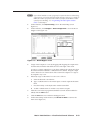
Virtualization/Control Software............................................................................................ 2-10
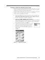
Installing the software....................................................................................................... 2-10
Starting the software......................................................................................................... 2-11
Post-Virtualization operations............................................................................................... 2-12
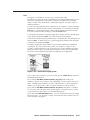
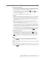
Wideband video, low resolution video, and sync connections
(wideband, video, and sync BMEs only)............................................................................ 2-12
Audio connections (audio BMEs only).............................................................................. 2-12
Remote control panel, front panel controller, and Ethernet connections..................... 2-14
Cabling and RJ-45 connector wiring............................................................................ 2-15
External sync connections (wideband and video BMEs only).......................................... 2-16
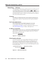
Other Settings............................................................................................................................. 2-18
Serial port protocol switches.................................................................................................. 2-18
Baud rate switches................................................................................................................... 2-18
Sync termination switches...................................................................................................... 2-18
IP parameters initialization.................................................................................................... 2-18
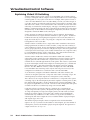
Chapter Three • Virtualization/Control Software .................................................... 3-1
Explaining Virtual I/O Switching....................................................................................... 3-2
Virtualization/Control Program.......................................................................................... 3-4
Creating a virtual I/O switching system (map)....................................................................... 3-5
Reassigning virtual I/O connectors........................................................................................ 3-10
Creating rooms within the system......................................................................................... 3-12
Remote controlling the Matrix 12800 system...................................................................... 3-14
Ties....................................................................................................................................... 3-15
Presets................................................................................................................................. 3-16
Save a preset................................................................................................................. 3-16
Recall or delete a preset............................................................................................... 3-16
Icons and captions.............................................................................................................. 3-17
Matrix 12800 Switchers • Table of Contents
i
PRELIMINARY
Pre-virtualization operations................................................................................................... 2-5
Table of Contents, cont’d
Programming the matrix offline (emulate mode).............................................................. 3-18
Saving and restoring matrix settings.................................................................................... 3-20
Creating program byte strings............................................................................................... 3-21
Ethernet operation.................................................................................................................. 3-21
PRELIMINARY
Logging on to the switcher via the Ethernet................................................................... 3-22
Ethernet protocol settings................................................................................................. 3-23
Address and Name fields.............................................................................................. 3-24
Date and Time (GMT) fields......................................................................................... 3-25
Administrator Password, User Password, and Mail Server Password fields.............. 3-25
E-mail Addressee fields................................................................................................. 3-26
Windows buttons and drop boxes........................................................................................ 3-27
Main screen menu bar options.......................................................................................... 3-27
File menu....................................................................................................................... 3-27
System-Config selection............................................................................................... 3-27
Tools menu.................................................................................................................... 3-28
Preferences menu......................................................................................................... 3-29
Virtual map screen menu bar options............................................................................... 3-30
Return to main.............................................................................................................. 3-30
Configure menu............................................................................................................ 3-30
Special Characters.................................................................................................................... 3-31
Chapter Four • Programming Guide.................................................................................... 4-1
RS-232/RS-422 Ports.................................................................................................................... 4-2
Ethernet (LAN) Port................................................................................................................... 4-3
Ethernet connection.................................................................................................................. 4-3
Default IP addresses................................................................................................................... 4-3
Establishing a connection......................................................................................................... 4-4
Number of connections............................................................................................................. 4-4
Host-to-Switcher Instructions.............................................................................................. 4-4
Switcher-Initiated Messages................................................................................................ 4-5
Switcher Error Responses...................................................................................................... 4-5
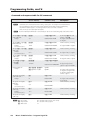
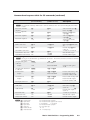
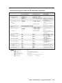
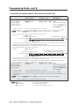
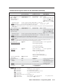
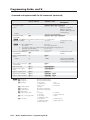
Using the Command and Response Tables.................................................................. 4-6
Symbol definitions................................................................................................................ 4-6
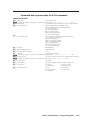
Command and response table for SIS commands................................................................. 4-8
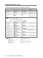
Symbol definitions.............................................................................................................. 4-17
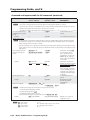
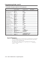
Command and response table for IP SIS commands........................................................... 4-18
Special Characters.................................................................................................................... 4-18
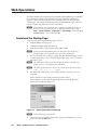
Chapter Five • Web Operations............................................................................................... 5-1
Download the Startup Page................................................................................................. 5-2
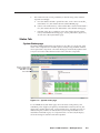
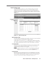
Status Tab......................................................................................................................................... 5-3
System Status page.................................................................................................................... 5-3
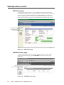
BME Status page........................................................................................................................ 5-4
MKP/MCP Status page............................................................................................................... 5-4
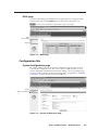
DSVP page................................................................................................................................... 5-5
ii
Matrix 12800 Switchers • Table of Contents
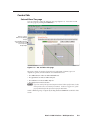
Configuration Tab....................................................................................................................... 5-5
System Configuration page...................................................................................................... 5-5
Administration fields............................................................................................................ 5-6
Matrix IP settings fields........................................................................................................ 5-6
Name field....................................................................................................................... 5-6
IP Address field............................................................................................................... 5-6
Gateway IP Address field................................................................................................ 5-6
Subnet Mask field........................................................................................................... 5-6
Hardware Address field.................................................................................................. 5-6
Email Settings page................................................................................................................... 5-7
Mail IP Address field............................................................................................................. 5-7
User Name field.................................................................................................................... 5-7
Password field....................................................................................................................... 5-7
Email Address fields............................................................................................................. 5-8
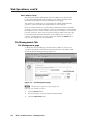
File Management Tab............................................................................................................... 5-8
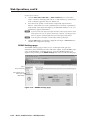
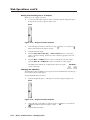
Control Tab...................................................................................................................................... 5-9
Set and View Ties page............................................................................................................. 5-9
RGBHV Settings page.............................................................................................................. 5-10
Changing the input gain and attenuation (systems with audio BMEs).......................... 5-11
Muting and unmuting one or all outputs........................................................................ 5-12
Changing the RGB delay.................................................................................................... 5-12
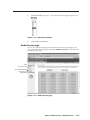
Global Presets page................................................................................................................. 5-13
Saving a preset................................................................................................................... 5-14
Recalling a preset............................................................................................................... 5-14
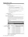
Physical Connections pages.................................................................................................... 5-14
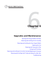
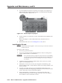
Chapter 6 • Upgrades and Maintenance.......................................................................... 6-1
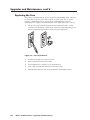
Opening and Closing the Matrix Switcher.................................................................. 6-2
Opening the switcher................................................................................................................ 6-2
Closing the switcher.................................................................................................................. 6-3
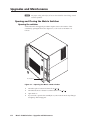
Removing and Installing the Fan Assembly............................................................... 6-4
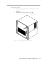
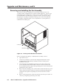
Removing and Installing the Power Supply Module............................................ 6-6
Removing the power supply module ..................................................................................... 6-6
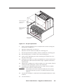
Installing the power supply module....................................................................................... 6-7
Replacing the Fuse..................................................................................................................... 6-8
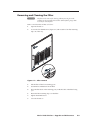
Removing and Cleaning the Filter.................................................................................... 6-9
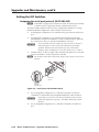
Setting the DIP Switches...................................................................................................... 6-10
Swapping the serial port protocol (RS-232/RS-422)............................................................ 6-10
Changing the serial port baud rate....................................................................................... 6-11
Changing the sync termination............................................................................................. 6-12
Removing and Installing the Controller Card and Replacing the
Firmware........................................................................................................................................ 6-13
Removing the primary or redundant controller card......................................................... 6-13
Updating the firmware........................................................................................................... 6-14
Installing the controller card.................................................................................................. 6-15
Matrix 12800 Switchers • Table of Contents
iii
PRELIMINARY
File Management page............................................................................................................. 5-8
Table of Contents, cont’d
Removing and Installing the I/O Card and Setting the Audio Gain........... 6-16
Removing the I/O card............................................................................................................. 6-18
Setting the default audio gain.............................................................................................. 6-19
Installing the I/O card.............................................................................................................. 6-20
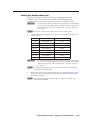
Troubleshooting......................................................................................................................... 6-21
Power supplies.......................................................................................................................... 6-21
Controller cards........................................................................................................................ 6-22
Input/output cards................................................................................................................... 6-23
Cooling...................................................................................................................................... 6-23
Communication with the FPC 5000....................................................................................... 6-23
Appendix A • Ethernet Connection..................................................................................... A-1
Ethernet Link................................................................................................................................ A-2
Ethernet connection................................................................................................................. A-2
Default address......................................................................................................................... A-2
PRELIMINARY
Pinging to determine Matrix IP Address............................................................................ A-3
Pinging to determine Web IP address................................................................................ A-3
Connecting as a Telnet client.................................................................................................. A-4
Telnet tips............................................................................................................................. A-4
Open............................................................................................................................... A-4
Escape character and Esc key........................................................................................ A-5
Local echo....................................................................................................................... A-5
Set carriage return-line feed......................................................................................... A-5
Close............................................................................................................................... A-5
Help................................................................................................................................ A-5
Quit................................................................................................................................. A-5
Subnetting — A Primer........................................................................................................... A-6
Gateways.................................................................................................................................... A-6
Local and remote devices......................................................................................................... A-6
IP addresses and octets............................................................................................................. A-6
Subnet masks and octets.......................................................................................................... A-6
Determining whether devices are on the same subnet...................................................... A-7
Appendix B • Reference Information.................................................................................B-1
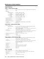
Specifications................................................................................................................................B-2
Part Numbers and Accessories............................................................................................B-5
Matrix 12800 BMEs....................................................................................................................B-5
Optional accessories..................................................................................................................B-5
Cables...........................................................................................................................................B-5
Bulk cable and termination tools........................................................................................B-5
Terminated cable assemblies...............................................................................................B-6
All trademarks mentioned in this manual are the properties of their respective owners.
68-556-01 C
10 11
iv
Matrix 12800 Switchers • Table of Contents
1
Chapter One
Introduction
About the Matrix 12800 Switchers
Features
Definitions
PRELIMINARY
Matrix 12800 Switchers
Introduction
About the Matrix 12800 Switchers
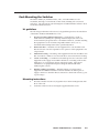
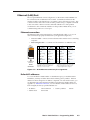
The Extron Matrix 12800 Series of switchers is a family of matrix switcher basic
module enclosures (BMEs) and an optional front panel controller (FPC 5000) that
allows you to create video and audio matrix systems with up to 128 inputs and
128 outputs specifically tailored to meet your requirements. The Matrix 12800
Series includes:
• Wideband video switcher BME — A rack mountable 10U switcher that
routes video (red [R], green [G], and blue [B] video planes, component video,
S-video, and composite video) from any input to any one or more outputs.
• Video switcher BME — A rack-mountable 10U switcher that routes
low resolution (NTSC, PAL, or SECAM) component video, S-video, and
composite video from any input to any one or more outputs.
• Sync switcher BME — A rack-mountable 10U switcher that routes horizontal
(H) and vertical (V) or composite sync from any input to any one or more
outputs.
• Audio switcher BME — A rack-mountable 10U switcher that routes balanced
or unbalanced audio from any input to any one or more outputs.
PRELIMINARY
• FPC 5000 Front Panel Controller — A rack-mountable device that permits
front panel configuration of the inputs and outputs and control of additional
system features.
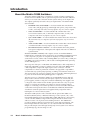
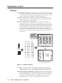
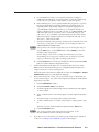
Wideband (RGBHV and RGBS) video requires at least one wideband BME to
handle the R, G, and B video planes and at least one sync BME to handle the H and V
or the composite sync plane. A complete 128 input by 128 output RGBHV and
audio matrix consists of three video switching BMEs (one each for R, G, and B), two
sync BMEs (one each for H and V), and an audio switching BME with, optionally,
an FPC 5000 (figure 1-1).
The rear panel of the sync or wideband video BME features a full complement of
input and output BNC connectors, and the rear panel of the audio BME features
a full complement of input and output captive screw connectors. The full
complement of connectors permits the switcher to be upgraded or expanded to
accommodate any system just by replacing or adding a new internal circuit card.
The circuit cards, fans, and power supplies are hot swappable, eliminating the need
to power down the matrix during field upgrades or expansion.
The microprocessor of the Matrix 12800 sync switcher BME monitors and selfdiagnoses the controller circuit cards, the input/output (I/O) circuit cards, the
power supplies, and the cooling fans. The dual redundant power supplies and
cooling fans of the switcher ensure reliable operation 24 hours a day. If a power
supply or a fan fails, the switcher can continue to operate normally without
danger of overheating. The switcher provides local visual and audio indications
of the failure and reports the failure via the Ethernet and RS-232/RS-422 links.
A technician can then replace the hot-swappable faulty component with no
interruption of a mission-critical system.
The Matrix 12800 system can be controlled with an optional FPC 5000 or via
the RS-232/RS-422, telnet, or Ethernet link using a control system, a PC, or the
Extron MKP 1200 remote keypad, MCP 1000 or MKP 1000 remote control panels,
or both. The FPC 5000 has a large LCD touch panel that allows direct access
and total control over all presets and switching functions. FPC 5000 menus
provide an intuitive interface for quick and easy setup and programming. The
Extron Simple Instruction Set (SIS™) is a set of basic ASCII code commands
that provide simple control through a third party control system or PC without
programming long, obscure strings of code.
1-2
Matrix 12800 Switchers • Introduction
EXT. FDD
K/B
MOUSE
NET
FPC 5000
PRN
COM4
COM3
COM2
COM1
VGA
DIO
I
o
AC 100V-230V
INPUT
Computer
Matrix 12800 Wideband Video
OUTPUTS
49
1
17
33
49
65
81
97
113
65
81
97
113
34
50
2
18
34
50
66
82
98
114
66
82
98
114
3
19
35
51
3
19
35
51
67
83
99
115
67
83
99
115
4
20
36
52
4
20
36
52
68
84
100
116
68
84
100
116
5
21
37
53
5
21
37
53
69
85
101
117
69
85
101
117
6
22
38
54
6
22
38
54
70
86
102
118
70
86
102
118
7
23
39
55
7
23
39
55
71
87
103
119
71
87
103
119
8
24
40
56
8
24
40
56
72
88
104
120
72
88
104
9
25
41
57
9
25
41
57
73
89
105
121
73
89
105
121
10
26
42
58
10
26
42
58
74
90
106
122
74
90
106
122
11
27
43
59
11
27
43
59
75
91
107
123
75
91
107
123
12
28
44
60
12
28
44
60
76
92
108
124
76
92
108
124
13
29
45
61
13
29
45
61
77
93
109
125
77
93
109
125
14
30
46
62
14
30
46
62
78
94
110
126
78
94
110
126
15
31
47
63
15
31
47
63
79
95
111
127
79
95
111
127
16
32
48
64
16
32
48
64
80
96
112
128
80
96
112
128
PRIMARY
Projector
B
G
R
H
V
Tx
Rx
Rx
RS 232/422
ETHERNET
PRIMARY
Rx
LISTED
1T23
I.T.E.
CAUTION
For protection against risk of
fire, replace only with same
type and rating of fuse.
SECONDARY
MADE IN USA
MCP/MKP COMM
5.0A MAX 50/60Hz FUSE 250V 5.0A T
100-240V
ANAHEIM, CA
A B C D E
5.0A MAX 50/60Hz FUSE 250V 5.0A T
100-240V
DISCONNECT BOTH POWER CORDS BEFORE SERVICING.
REDUNDANT AC
POWER INPUT
Tx
REDUNDANT
RS 232/422
OUT
PRIMARY
OUT
SYNC
POWER SUPPLIES
+V -V
PRIMARY AC
POWER INPUT
Rx
BME COMM
ADDRESS
FPC COMM
IN
REDUNDANT
Tx
+
Rx
-
4
Tx
Tx
CPU STATUS
120
Tx
BME
Rx
33
18
IN
R
G
B
INPUTS
17
2
PRELIMINARY
OUTPUTS
1
Matrix 12800 Sync
OUTPUTS
OUTPUTS
49
1
17
33
49
65
81
97
113
65
81
97
113
34
50
2
18
34
50
66
82
98
114
66
82
98
114
3
19
35
51
3
19
35
51
67
83
99
115
67
83
99
115
4
20
36
52
4
20
36
52
68
84
100
116
68
84
100
116
5
21
37
53
5
21
37
53
69
85
101
117
69
85
101
117
6
22
38
54
6
22
38
54
70
86
102
118
70
86
102
118
7
23
39
55
7
23
39
55
71
87
103
119
71
87
103
119
8
24
40
56
8
24
40
56
72
88
104
120
72
88
104
9
25
41
57
9
25
41
57
73
89
105
121
73
89
105
121
10
26
42
58
10
26
42
58
74
90
106
122
74
90
106
122
11
27
43
59
11
27
43
59
75
91
107
123
75
91
107
123
12
28
44
60
12
28
44
60
76
92
108
124
76
92
108
124
13
29
45
61
13
29
45
61
77
93
109
125
77
93
109
125
14
30
46
62
14
30
46
62
78
94
110
126
78
94
110
126
15
31
47
63
15
31
47
63
79
95
111
127
79
95
111
127
16
32
48
64
16
32
48
64
80
96
112
128
80
96
112
128
PRIMARY
IN
Tx
Rx
RS 232/422
RS 232/422
ETHERNET
PRIMARY
Rx
LISTED
1T23
I.T.E.
CAUTION
For protection against risk of
fire, replace only with same
type and rating of fuse.
SECONDARY
MADE IN USA
MCP/MKP COMM
5.0A MAX 50/60Hz FUSE 250V 5.0A T
100-240V
ANAHEIM, CA
A B C D E
5.0A MAX 50/60Hz FUSE 250V 5.0A T
100-240V
DISCONNECT BOTH POWER CORDS BEFORE SERVICING.
REDUNDANT AC
POWER INPUT
Tx
REDUNDANT
Rx
OUT
PRIMARY
Tx
SYNC
POWER SUPPLIES
+V -V
PRIMARY AC
POWER INPUT
Rx
ADDRESS
BME COMM
REDUNDANT
Tx
+
OUT
-
4
120
Rx
CPU STATUS
Tx
Tx
BME
Rx
33
18
IN
V
H
INPUTS
17
2
FPC COMM
1
Matrix 12800 Audio
BME COMM
Inter Connecting
Cable
INPUTS
17-24
25-32
33-40
41-48
49-56
57-64
65-72
73-80
81-88
89-96
97-104
105-112 113-120 121-128
Tx
OUTPUTS
BME
CPU STATUS
-
Rx
9-16
Tx
1-8
Audio
Rx
Audio
Tx
Rx
RS 232/422
RS 232/422
Rx
Rx
Tx
ETHERNET
PRIMARY
Rx
LISTED
1T23
I.T.E.
CAUTION
SECONDARY
MADE IN USA
MCP/MKP COMM
5.0A MAX 50/60Hz FUSE 250V 5.0A T
100-240V
ANAHEIM, CA
For protection against risk of
fire, replace only with same
type and rating of fuse.
A B C D E
5.0A MAX 50/60Hz FUSE 250V 5.0A T
100-240V
DISCONNECT BOTH POWER CORDS BEFORE SERVICING.
REDUNDANT AC
POWER INPUT
Tx
REDUNDANT
PRIMARY AC
POWER INPUT
Tx
PRIMARY
OUT
BME COMM
REDUNDANT
POWER SUPPLIES
+V -V
IN
+
FPC COMM
PRIMARY
4
ADDRESS
Figure 1-1 — Typical Matrix 12800 application
Matrix 12800 Switchers • Introduction
1-3
Introduction, cont’d
Features
Input and output connectors — All connectors are clearly labeled as either input or
output for easy installation. With the Extron virtualization/control software,
a visual map can be printed for easy representation of the virtual I/Os. This
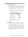
feature reduces the time required for setup and programming.
Bandwidth — Bandwidth is a minimum of 375 MHz (-3 dB), fully loaded. This
high bandwidth allows Extron switchers to switch everything from NTSC
video to high-resolution computer video.
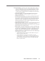
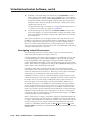
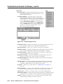
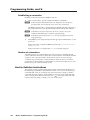
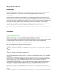
Digital Sync Validation Processing (DSVP™) — In critical environments or
unmanned, remote locations, it is vital to know that sources are active and
switching. The exclusive Extron DSVP confirms that input sources are active
by scanning all sync inputs for active signals. DSVP provides instantaneous
frequency feedback for composite sync or separate horizontal and vertical
sync signals via the RS-232/RS-422 port of the switcher. The frequency
information can be displayed on any control system or in a Windows®-based
control program on a local-area network (LAN) or internet (IP) connection
(figure 1-2).
PRELIMINARY
Input # 01
Signal: PRESENT
Sync Type: H&V
Vertical Freq.: 60 Hz
Horz Freq.: 31.5 kHz
Input Horz. Vert.
RS-232/
422
Ethernet
MATRIX INPUT STATUS
Input # 01
Input # 02
Input # 03
Input # 04
Signal: PRESENT
Sync Type: H&V
Vertical Freq.: 60 Hz
Horz Freq.: 31.5 kHz
Signal: PRESENT
Sync Type: H&V
Vertical Freq.: 60 Hz
Horz Freq.: 31.5 kHz
Signal: PRESENT
Sync Type: H&V
Vertical Freq.: 60 Hz
Horz Freq.: 31.5 kHz
Signal: PRESENT
Sync Type: H&V
Vertical Freq.: 60 Hz
Horz Freq.: 31.5 kHz
Input # 05
Input # 06
Input # 07
Input # 08
Signal: PRESENT
Sync Type: H&V
Vertical Freq.: 60 Hz
Horz Freq.: 31.5 kHz
Signal: PRESENT
Sync Type: H&V
Vertical Freq.: 60 Hz
Horz Freq.: 31.5 kHz
Signal: PRESENT
Sync Type: H&V
Vertical Freq.: 60 Hz
Horz Freq.: 31.5 kHz
Signal: PRESENT
Sync Type: H&V
Vertical Freq.: 60 Hz
Horz Freq.: 31.5 kHz
Input # 09
Input # 10
Input # 11
Input # 12
Signal: PRESENT
Sync Type: H&V
Vertical Freq.: 60 Hz
Horz Freq.: 31.5 kHz
Signal: PRESENT
Sync Type: H&V
Vertical Freq.: 60 Hz
Horz Freq.: 31.5 kHz
Signal: PRESENT
Sync Type: H&V
Vertical Freq.: 60 Hz
Horz Freq.: 31.5 kHz
Signal: PRESENT
Sync Type: H&V
Vertical Freq.: 60 Hz
Horz Freq.: 31.5 kHz
01
31.50
60.00
02
31.50
60.00
03
31.50
60.00
04
48.01
67.50
3rd party control system
05
48.01
67.50
OR
06
48.01
67.50
07
48.01
67.50
08
61.55
72.00
09
61.55
72.00
10
61.55
72.00
11
61.55
72.00
12
61.55
72.00
•
•
•
•
•
•
•
•
•
Windows-based control program on
LAN or IP connection
Figure 1-2 — DSVP data display
Rooming — Each Matrix 12800 system can be programmed to group multiple
outputs to specific “rooms”, allowing them to have their own presets. The
system can have up to 32 rooms, each of which can have up to 10 presets.
Triple-Action Switching™ (RGB delay) — RGB delay blanks the screen when the
matrix switcher switches to a new RGB video source. The new sync signals
precede the RGB signals, so there is no noise-filled scramble shown during
the transition. The time delay between the RGB and sync signals is user
adjustable up to five seconds via SIS and Windows program control.
1-4
Matrix 12800 Switchers • Introduction
The MKP 1200 is directly connected to the MCP/MKP Comm port on
BME 0 of the Matrix 12800 system.
The MCP 1000 master control panel is connected to one of the
RS-232/RS-422 ports. MCP 1000 slave control panels, MKP 1000 slave
control keypads, or both are connected to the MCP 1000 master control
panel. The remote control devices are easy to use and provide tactile
buttons for quick selection.
Matrix 12800 Switchers • Introduction
1-5
PRELIMINARY
Operational flexibility — Operations such as input/output selection, setting of
presets, and adjustment of audio levels can be performed at the front panel
controller, over the primary and secondary RS-232/RS-422 links, or via the
Ethernet link. The RS-232/RS-422 links allow remote control via two PCs
or control systems. The Ethernet link allows multiple remote links with two
levels of password protection.
• Front Panel Controller — The optional FPC 5000 Front Panel Controller
allows easy configuration of inputs and outputs, as well as control of
additional system features.
• Virtualization/control software — For serial port or Ethernet remote control
from a PC, Extron includes its Windows-based control software with every
matrix switcher. This icon-driven software uses a drag-and-drop-point-andclick interface to make I/O configuration and other customization functions
simple and convenient. The Windows-based control program also has an
emulation mode that lets you create a switcher configuration file at the home
office and then download it for use on site.
• Simple Instruction Set (SIS) — The SIS is a set of basic ASCII code commands
that provide simple control through a PC or control system. Instead of
programming in long, obscure strings of code, SIS makes it easy to operate the
matrix using serial port or Ethernet control.
• Remote control — The Matrix 12800 switchers are remote controllable, using
an MKP 1200 control keypad, an MCP 1000 master control panel, or both and
any combination of MCP 1000 slave control panels or MKP 1000 slave control
keypads, or both. Each MCP 1000 can be used for one-touch switching for a
particular output and for selecting global presets. The MKP 1200 and each
MKP 1000 is dedicated to an output and can be used to select a different input
for that output or to select a preset.
Introduction, cont’d
PRELIMINARY
Operational reliability — The Matrix 12800 can support round-the-clock operation
in mission-critical applications, using a combination of self-diagnosis, hotswappable components, and optional redundant components.
• Advanced computer-aided diagnostics — The Matrix 12800 performs self
diagnostics, 24 hours a day, of the I/O cards, primary and redundant power
supply voltages, controller cards, cooling status, and the overall functional
status of the matrix. The status can be monitored off-site for unmanned
applications via the Ethernet or RS-232/RS-422 communications ports.
• Dual redundant, hot swappable controller cards — The primary and
redundant controller cards are internally mounted. The primary and
redundant controller cards can each initiate configuration changes or other
matrix switcher operations. Each card has an RS-232/RS-422 port for
connection of a PC or control system. Redundant controllers mean zero
downtime for the system. There is no loss of functionality should one of the
controller cards fail. A failed controller card is easily replaceable through the
front door with no tools required. Hot swappable controllers allow the user to
replace either at any time — without powering down the matrix.
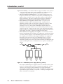
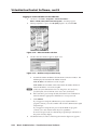
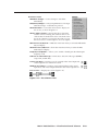
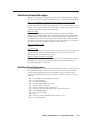
• Dual redundant, hot swappable power supplies — The internally mounted
primary and redundant power supplies are configured to automatically switch
over from a primary supply to a hot redundant supply in the case of a failure.
The complete power circuit, from the plug, through the power supplies, to
the insertion of the power onto the power distribution plane, is separate
and redundant (figure 1-3). If the installation includes uninterruptible or
completely separate power sources, the switcher remains powered up through
any power interruption short of a simultaneous loss of power on both power
sources.
AC
Power
AC
Power
Primary Redundant
Power
Power
Supply
Supply
A
A
Primary Redundant
Power
Power
Supply
Supply
B
B
Figure 1-3 — Redundant power supply backs up primary
The ready hot redundant power supplies mean zero downtime for the system
and no loss of functionality should one of the primary supplies fail. Should
a primary power supply fail, the redundant power supply immediately
assumes the load of the failed primary supply. A failed power supply is easily
replaceable through the front door at any time — without powering down the
matrix, and with no tools required.
1-6
Matrix 12800 Switchers • Introduction
• Dual redundant, hot swappable cooling fans — Four cooling fans are
provided for ventilation and heat management. Fan and temperature sensors
identify problems, which are reported locally with visual indications and
remotely via the Ethernet and serial port links. Fans and the filter are easily
replaceable through the front door with only a screwdriver required.
• Field upgradable, hot swappable modular design — The architecture of the
Matrix 12800 allows you to repair, upgrade, or expand the matrix by simply
installing a new I/O module. Hot swappable components allow the user to
replace any I/O module at any time — without powering down the matrix.
• Low mean-time-to-repair — Full access to all of the internal modules and
assemblies is available through the front door, providing easy maintenance
and serviceability.
Switching flexibility — Individually buffered, independent matrix switched
outputs. Any input can be switched to any or all outputs within a BME.
Channel to channel isolation — The Matrix 12800 Series provides excellent
isolation between channels and extremely low electromagnetic emissions —
perfect for minimizing signal leakage in high security or government
environments.
Presets — The Matrix 12800 can be configured for several different applications
without the need to change settings each time the application changes.
Video genlock — The Matrix 12800 includes broadcast quality NTSC, PAL, or
SECAM video genlock capabilities that enable vertical interval switching.
Vertical interval switching results in smooth, seamless transitions when
switching between inputs.
Two AC power inputs — For added power reliability, some 24-hour environments
provide two separate AC power sources, one as primary and the second
as backup. The Matrix 12800 has two AC power inputs for continuous
connection to both power sources.
Password protection — There are two levels of password protection at log-in:
administrator and user. Administrators have full access to all Matrix 12800
switching capabilities and editing functions. Users can select inputs and
outputs, set and recall presets, and view all settings with the exception of
passwords.
Rack mount — The switchers are mountable in any conventional 19-inch wide rack.
Matrix 12800 Switchers • Introduction
1-7
PRELIMINARY
SmartControl microprocessor — The SmartControl microprocessor can determine
how many inputs and outputs are in use and configures itself for ease of use
in any application.
Introduction, cont’d
Definitions
The following terms apply to Extron Matrix Switchers, and are used throughout
this manual:
Tie — An input-to-output connection.
Set of ties — An input tied to two or more outputs. (An output can never be tied
to more than one input.)
Configuration — May consist of one tie or one or more sets of ties.
Current configuration — The configuration that is currently being used (also
called configuration 0).
Global memory preset — A configuration that has been stored. The Matrix 12800
can support up to 64 global presets. When a global preset is retrieved from
memory, it becomes the current configuration.
Room — A Room consists of a smaller subset of virtual outputs that are logically
related to each other, as determined by the operator. The Matrix 12800
supports up to 32 rooms, each of which consists of from 1 to 16 virtual
outputs.
PRELIMINARY
Room memory preset — A configuration consisting of virtual outputs in a single
room that has been stored. When a room preset is retrieved from memory,
it becomes the current configuration. The Matrix 12800 supports up to 10
room presets per room. Selecting a room preset only changes the ties to
outputs that are assigned to that room. All other ties outside the room are not
affected.
1-8
Matrix 12800 Switchers • Introduction
2
Chapter Two
Installation
Installation Overview
Rack Mounting the Switcher
Rear Panel Connections and Settings
Other Settings
PRELIMINARY
Matrix 12800 Switchers
Installation
Installation Overview
The Matrix 12800 BMEs that make up a Matrix 12800 system can be installed in a
rack or a cabinet, if desired. Each BME must be connected on a daisy chain to the
other BMEs in the system and cannot be separated from the other BMEs by more
than 25 feet (7.6 m). The BMEs can be rack- or cabinet-mounted in any order.
Give careful consideration to the location of the equipment in a room. Poor
planning can result in problems. The number of cables involved can result in a
cluttered appearance. Power and ventilation requirements are a consideration.
Although a BME is not noisy by itself, the background noise generated by a rack of
Matrix 12800 switchers could be distracting.
The following restrictions apply to installing BMEs:
One BME must be assigned the address of BME 0.
A sync switcher cannot be BME 0.
Address assignments must be sequential and may not skip numbers, with the
exception of the BME sequentially after the audio BME.
• An audio BME uses two virtual addresses, but is physically assigned a single
number. For example, an audio BME at physical address 5 occupies virtual
addresses 5 and 6. A subsequent BME should be set to physical address 7.
• Address assignments of 0 through 8 are valid; a BME that is assigned address
9 is ignored.
• A system is limited to one or two audio BMEs.
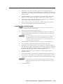
Install and set up a Matrix 12800 system for operation as follows:
PRELIMINARY
•
•
•
1 Disconnect power from all of the equipment, including all video sources
(such as computers or DVD players), and the devices that receive the matrixswitched video, audio, or both.
2 Rack mount the switcher, if desired.
3 Ground the BMEs using the ground terminal (most models).
4 Set the BME addresses.
5 Connect the BME COMM interconnecting cables.
6 Connect one or two serial cables to the RS-232/RS-422 ports of BME 0 and to
the PCs or control systems.
7 Connect the AC power cables to the BMEs.
8 Reseat all circuit cards. See chapter 6, “Upgrades and Maintenance”.
N Printed circuit cards can become dislodged from their edge connectors during
shipment. Reseat all I/O and controller circuit cards before initial power up.
9 Apply AC power to the BMEs and verify the BMEs power up normally.
10 Load the Matrix 128000 System Virtualization Control software (see
“Virtualization/Control Software”, later in this chapter).
11 Virtualize the Matrix 12800 system if required (see chapter 3, “Virtualization/
Control Software”).
12 Connect all input and output cabling to the Matrix 12800 system.
13 Connect all desired remote control panels and remote keypads and connect
the switcher to the Ethernet Local Area Network (LAN), if desired.
14 Set the sync termination switches, if desired.
15 If using the Ethernet capability, initialize the Internet protocol (IP) parameters.
See chapter 3, “Virtualization/Control Software”.
2-2
Matrix 12800 Switchers • Installation
Rack Mounting the Switcher
The Matrix 12800 sync, wideband video, video, and audio BMEs are rackmountable, 10U high, 17.5-inch wide (19-inch wide, including rack ears) metal
enclosures. The appropriate rack mounting kit is included with the switcher. Rack
mount the switcher as follows:
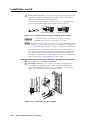
UL guidelines
1.
Elevated operating ambient temperature — If installed in a closed or
multi-unit rack assembly, the operating ambient temperature of the rack
environment may be greater than room ambient. Therefore, consider installing
the equipment in an environment compatible with the 122 °F (+50 °C)
maximum ambient temperature (Tma) specified by Extron.
2.
Reduced air flow — Installation of the equipment in a rack should be such
that the amount of air flow required for safe operation of the equipment is not
compromised.
3.
Mechanical loading — Mounting of the equipment in the rack should be such
that a hazardous condition is not achieved due to uneven mechanical loading.
4.
Circuit overloading — Consideration should be given to the connection of the
equipment to the supply circuit and the effect that overloading of the circuits
might have on overcurrent protection and supply wiring. Appropriate
consideration of equipment nameplate ratings should be used when
addressing this concern.
5.
Reliable earthing (grounding) — Reliable earthing of rack-mounted
equipment should be maintained. Particular attention should be given to
supply connections other than direct connections to the branch circuit (e.g. use
of power strips.
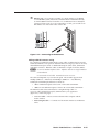
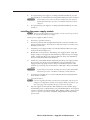
Mounting instructions
1.
Insert the switcher into the rack, align the holes in the mounting bracket with
those of the rack.
2.
Secure the switcher to the rack using the supplied machine screws.
Matrix 12800 Switchers • Installation
2-3
PRELIMINARY
The following Underwriters Laboratories (UL) guidelines pertain to the installation
of the Matrix 12800 switcher BME into a rack.
Installation, cont’d
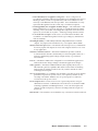
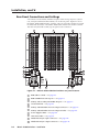
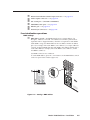
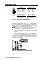
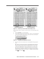
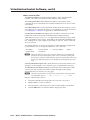
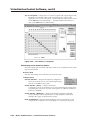
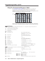
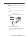
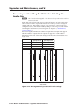
Rear Panel Connections and Settings
All connectors and switches (with the exception of the serial port protocol, baud
rate, and sync termination DIP switches) are on the rear panel. Figure 2-1 shows
the Matrix 12800 wideband video switcher. The sync and video switcher is housed
in similar 10U enclosures. The Matrix 12800 audio switcher is housed in a similar
10U enclosure, but with 3.5 mm, 5-pole captive screw connectors.
10
OUTPUTS
49
65
81
97
113
65
81
97
113
2
18
34
50
2
18
34
50
66
82
98
114
66
82
98
114
3
19
35
51
3
19
35
51
67
83
99
115
67
83
99
115
4
20
36
52
4
20
36
52
68
84
100
116
68
84
100
116
5
21
37
53
5
21
37
53
69
85
101
117
69
85
101
117
6
22
38
54
6
22
38
54
70
86
102
118
70
86
102
118
7
23
39
55
7
23
39
55
71
87
103
119
71
87
103
119
8
24
40
56
8
24
40
56
72
88
104
120
72
88
104
120
9
25
41
57
9
25
41
57
73
89
105
121
73
89
105
121
10
26
42
58
10
26
42
58
74
90
106
122
74
90
106
122
11
27
43
59
11
27
43
59
75
91
107
123
75
91
107
123
12
28
44
60
12
28
44
60
76
92
108
124
76
92
108
124
13
29
45
61
13
29
45
61
77
93
109
125
77
93
109
125
14
30
46
62
14
30
46
62
78
94
110
126
78
94
110
126
15
31
47
63
15
31
47
63
79
95
111
127
79
95
111
127
16
32
48
64
16
32
48
64
80
96
112
128
80
96
112
128
PRIMARY
CAUTION
For protection against risk of
fire, replace only with same
type and rating of fuse.
16
4
15
2
Rx
3
Rx
Tx
RS 232/422
PRIMARY
SECONDARY
Tx
LISTED
1T23
I.T.E.
Rx
ETHERNET
MADE IN USA
MCP/MKP COMM
5.0A MAX 50/60Hz FUSE 250V 5.0A T
100-240V
5
ANAHEIM, CA
A B C D E
5.0A MAX 50/60Hz FUSE 250V 5.0A T
100-240V
Tx
REDUNDANT AC
POWER INPUT
Rx
Tx
REDUNDANT
PRIMARY AC
POWER INPUT
RS 232/422
OUT
FPC COMM
BME COMM
SYNC
PRIMARY
6
13
IN
REDUNDANT
POWER SUPPLIES
+V -V
OUT
+
Tx
CPU STATUS
-
4
Rx
33
Rx
17
Tx
1
ADDRESS
7
OUTPUTS
49
BME
1
INPUTS
33
IN
8
10
17
DISCONNECT BOTH POWER CORDS BEFORE SERVICING.
PRELIMINARY
1
9
14
Figure 2-1 — Matrix 12800 wideband switcher rear panel features
a
b
c
d
e
f
g
h
i
j
2-4
BME address switch — See page 2-5.
BME COMM interconnect ports — See page 2-6.
Primary and Secondary RS-232/RS-422 ports — See page 2-7.
Ground terminal — See page 2-8.
Primary and Redundant AC Power Input connectors — See page 2-8.
Primary and Redundant AC Power Input switches — See page 2-9.
Power Supplies LEDs — See page 2-9.
CPU Status LEDs — See page 2-9.
Wideband and sync input connectors — See page 2-12.
Wideband and sync output connectors — See page 2-12.
Matrix 12800 Switchers • Installation
k
l
m
n
o
p
Balanced and unbalanced audio input connectors — See page 2-13.
Audio outputs connectors — See page 2-14.
FPC Comm port — (FUTURE CAPABILITY)
MCP/MKP Comm ports — See page 2-14.
Ethernet port — See page 2-15.
External Sync connectors — See page 2-16.
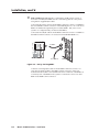
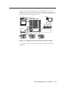
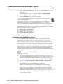
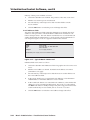
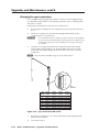
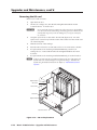
Pre-virtualization operations
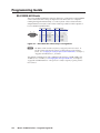
a
BME address switch — Each BME must be set to a unique address of 0
through 8. Address 9 is invalid. The addresses used in the system must be
sequential with no skipped numbers, other than as required for audio BMEs.
Audio BMEs occupy two BME addresses: the set address and the set address
plus 1 (for example, if the audio BME is set to address 3, it occupies addresses
3 and 4). Set the next BME after the audio BME to the address number plus 2
of the audio BME (for example, if the audio BME is set to address 3, set the
next BME to address 5).
Sync BMEs cannot be set to address 0.
To set the BME address, press the + and - buttons on the BME Address switch
on the rear panel of the switcher (figure 2-2).
BM
E
AD
-
PRIMARY
4
+
IN
4
REDUNDANT
ADDRESS
SYNC
POWER SUPPLIES
+V -V
OUT
REDUNDANT
AD
5.0A MAX 50/60Hz FUSE 250V 5.0A T
DR
ES
S
S
US
TAT
US
PR
IMA
RE RY
DU
ND
AN
T
PO
+v WER
SU
-v
PP
LIE
IN
S
PR
IMA
SY
R
PR
Y
R
NC
PO IMAR EDUN
WE Y A
DA
R IN C
NT
PU
T
RE
D
OU
PO UNDA
T
WE NT
R IN AC
PU
T
100-240V
100-240V
100-240V
DISCONNECT BOTH POWER CORDS BEFORE SERVICING.
REDUNDANT AC
POWER INPUT
5.0A MAX 50/60Hz FUSE 250V 5.0A T
PRIMARY AC
POWER INPUT
ES
0.5A MAX 50/60Hz
PRIMARY
CP
DR
CPU STATUS
0.5A MAX 50/60Hz
E
BME
1
4
AN
MAAHE
DE IM,
IN CA
US
A
100-240V
BM
Fo
r
fire proteCAU
typ , rep ctionTION
e a lace ag
nd on ain
rati ly st
ng with risk
of
fus sam of
e. e
Figure 2-2 — Setting a BME address
Matrix 12800 Switchers • Installation
2-5
PRELIMINARY
BME settings
Installation, cont’d
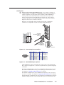
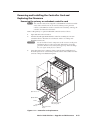
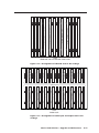
b
BME COMM interconnect ports — If the Matrix 12800 system consists of
more than one BME, the BMEs must be connected together in a daisy chain
using Extron-supplied RJ-45 cables.
Connect the first daisy chain from the BME Comm Out connector on BME 0 to
the nearest BME Comm In connector on the BME (figure 2-3). In a rack whose
BMEs are numbered sequentially, this would be BME 1. But, since not all
systems are configured alike, call this module BME n.
Connect the next RJ-45 cable from the BME Comm Out connector on BME n to
the BME Comm In connector on nearest unconnected BME (BME n+1) .
80
96
11
Tx
Rx
Rx
FPC COMM
BME COMM
OUT
Tx
Rx
PRIMARY
RS 232/422
Tx
SECONDARY
Rx
Rx
Tx
BME 1
A B C D E
MCP/MKP COMM
From BME 0
RS 232/422
Rx
Tx
ETHERNET
RS 232/422
Rx
Rx
RS 232/422
SECONDARY
Tx
8
IN
To BME 2
12
Rx
Tx
Rx
Rx
PRIMARY
Tx
Tx
ETHERNET
MCP/MKP COMM
A B C D E
PRELIMINARY
Rx
Tx
Rx
FPC COMM
OUT
2
IN
BME COMM
Tx
Tx
2
Figure 2-3 — Daisy-chaining BMEs
2-6
Continue connecting RJ-45 cables from the BME Comm Out connector on
each daisy-chained module to the BME Comm In connector on the next
module until all modules are included in the chain. When all of the BMEs are
connected, each of the BMEs in the system is connected to at least one other
BME via the BME Comm connectors.
Matrix 12800 Switchers • Installation
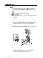
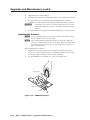
Serial ports
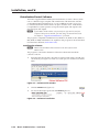
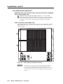
c
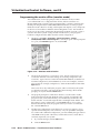
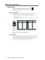
Primary and Secondary RS-232/RS-422 ports — For systems consisting of
a single switcher or for BME 0 on a multi-BME system, connect host devices
(such as computers or touch panel control systems) or MCP 1000 remote
control panels (see the MCP 1000 Remote Control Panel User Guide) to the
Primary and Secondary RS-232/RS-422 ports (figure 2-4). These 9-pin D
connectors provide for serial RS-232/RS-422 control of the matrix switcher.
Figure 2-5 shows how to wire the connectors.
Both ports are connected to both controller circuit cards; a redundant
controller is not required to use the Secondary RS-232/RS-422 port.
80
96
11
12
Tx
FPC COMM
To Secondary
Host System/Device
Serial Port
6
9
1
5
Male
Connector
Figure 2-4 — Connecting host controllers
5
1
9
6
Female
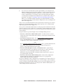
Pin RS-232 Function
RS-422 Function
Not used
—
1
TX+ Transmit data (+)
TX Transmit data
2
TX- Transmit data (-)
RX Receive data
3
RX+ Receive data (+)
Not used
—
4
RX- Receive data (-)
Gnd Signal ground Gnd Signal ground
5
Not used
—
Not used
6
—
Not used
—
Not used
7
—
Not used
—
Not used
8
—
Not used
—
Not used
9
—
Figure 2-5 — RS-232/RS-422 port pinout
After the BMEs have been virtualized, the system can be controlled through
this connection using the PC or other host system that can generate the proper
commands.
The Matrix 12800 Switchers are factory configured for RS-232 control. To use
the switcher under RS-422 control, you must change an internal DIP switch.
See chapter 6, “Upgrades and Maintenance” for details.
The default communications rate is 9600 baud. Baud rates of 19.2, 38.4, and
115 are also available. See chapter 6, “Upgrades and Maintenance” for details.
If equipped with a redundant controller, the primary and redundant controllers
must be configured for the same communications protocol and transfer rates.
Matrix 12800 Switchers • Installation
2-7
PRELIMINARY
Tx
Rx
PRIMARY
RS 232/422
Tx
Rx
Rx
SECONDARY
RS 232/422
Rx
ETHERNET
Tx
Tx
A B C D E
Tx
Rx
3
RS 232/422
Rx
Tx
RS 232/422
PRIMARY
SECONDARY
MCP/MKP COMM
Rx
Tx
Rx
FPC COMM
Tx
OUT
BME COMM
IN
Rx
Tx
ETHERNET
Rx
Tx
A B C D E
MCP/MKP COMM
To Primary
Host System/Device
Serial Port
Rx
OUT
Rx
8
IN
BME COMM
Tx
2
Installation, cont’d
Ground
d
Ground terminal — If the power outlets do not provide connections to
the protective ground of the building, connect ground straps between this
terminal lug on all BMEs and a hard building ground. Secure the ground
straps with the nut and washer included with each BME.
N You are responsible for providing the ground straps.
N Some earlier BMEs do not have the ground terminal.
PRELIMINARY
UL guidelines for ground
N The equipment is intended to be used in a location having equipotential bonding.
1.
The building installation shall provide a means for connection to protective
earth; and
2.
The equipment is to be connected to that means; and
3.
A SERVICE PERSON shall check whether or not the socket-outlet from
which the equipment is to be powered provides a connection to the building
protective earth (ground). If not, the SERVICE PERSON shall arrange for the
installation of a PROTECTIVE EARTHING CONDUCTOR from the separate
protective earthing terminal to the protective earth wire in the building.
Power
e
Primary and Redundant AC Power Input connectors — Connect a standard
IEC power cord between the rear panel Primary AC Power Input connector
and a 100 to 240VAC, 50 Hz or 60 Hz power source (figure 2-6).
BM
E
4
AD
+
IN
SYNC
POWER SUPPLIES
+V -V
OUT
PRIMARY
REDUNDANT
0.5A MAX 50/60Hz
5.0A MAX 50/60Hz FUSE 250V 5.0A T
100-240V
DISCONNECT BOTH POWER CORDS BEFORE SERVICING.
5.0A MAX 50/60Hz FUSE 250V 5.0A T
REDUNDANT AC
POWER INPUT
100-240V
PRIMARY AC
POWER INPUT
US
TAT
US
PR
IMA
RE RY
DU
ND
AN
T
PO
+v WER
SU
-v
PP
LIE
IN
S
PR
IMA
SY
R
PR
Y
R
NC
PO IMAR EDUN
WE Y A
DA
R IN C
NT
PU
T
RE
D
OU
PO UNDA
T
WE NT
R IN AC
PU
T
REDUNDANT
ADDRESS
S
Primary AC
Power Input
5
0.5A MAX 50/60Hz
PRIMARY
ES
AN
MAAHE
DE IM,
IN CA
US
A
100-240V
-
4
CP
DR
CPU STATUS
100-240V
BME
Fo
r
fire proteCAU
typ , rep ctionTION
e a lace ag
nd on ain
rati ly st
ng with risk
of
fus sam of
e. e
Redundant AC
Power Input
Figure 2-6 — Connecting power
2-8
If this BME is equipped with redundant power supplies A and B, connect a
second IEC power cord between the Redundant AC Power Input connector
and either an uninterruptible power source or a power source that is
completely independent from the primary power source.
Matrix 12800 Switchers • Installation
f
Primary and Redundant AC Power Input switches — For BME 0 to recognize
all of the BMEs in the daisy chain, BME 0 may not be powered on before the
other BMEs. Rather, turn on BME 0 at the same time or after the other BMEs.
Toggle the Primary AC Power Input switch to the on ( ) position to power up
the BME.
If this BME is equipped with redundant power supplies A and B, toggle the
Redundant AC Power Input switch to the on ( ) position.
g
Power Supplies LEDs — On power up, observe that the +V and -V Primary
LEDs light to indicate that the supplied power is within
POWER SUPPLIES
tolerance.
+V -V
PRIMARY
REDUNDANT
h
If this BME is equipped with redundant power supplies
A and B, on power up, observe that the +V and -V
Redundant LEDs light to indicate that the supplied
power is within tolerance. If the primary A or B
power supply fails, the Primary LEDs go out and the
Redundant LEDs blink to indicate that the redundant B
or A power supply is supplying the load.
CPU Status LEDs — On power up, observe that the Primary CPU Status LED
blinks initially to indicate that internal startup
CPU STATUS
housekeeping is occurring and then, assuming that the
PRIMARY
primary controller is the active controller, blinks to indicate
that the primary controller is ready.
REDUNDANT
If this BME is equipped with a redundant controller
card, observe that the Redundant CPU Status LED blinks
initially and then, assuming that the redundant controller
is the standby controller, lights steadily to indicate that the
redundant controller is ready. If the primary controller fails,
the Primary CPU Status LED goes out and the Redundant
CPU Status LED blinks to indicate that the redundant
controller is the active controller.
N Both LEDs blink at startup. After startup, the LED for the active controller
blinks and the LED for the standby controller lights steadily.
Matrix 12800 Switchers • Installation
2-9
PRELIMINARY
N During shipment, circuit cards can become dislodged from their edge connectors
during shipment. Reseat all I/O and controller cards before initial power up.
See chapter 6, “Upgrades and Maintenance”, for the applicable procedures.
Installation, cont’d
Virtualization/Control Software
The Extron-supplied Matrix 12800 System Virtualization/Control software, which
runs on a Windows-type computer and communicates with the matrix switcher
via the Ethernet, RS-232/RS-422 ports, or each on BME 0, provides an easy way
to virtualize the matrix switcher and to set up ties and sets of ties. Virtualization
is required before system operation to map the virtual inputs and outputs to the
physical inputs and outputs.
N If your Matrix 12800 switcher was previously set up for RS-232, and your
computer comm port uses RS-422, you must change an internal DIP switch.
See Chapter 6, “Upgrades and Maintenance”, for details.
The program is compatible with Windows 95, Windows 98, Windows NT, Windows
ME, Windows 2000, and Windows XP. Updates to this program can be downloaded
from the Extron Web site (www.extron.com).
Installing the software
N Matrix 3200 and Matrix 6400 switchers use the same software as the
Matrix 12800.
PRELIMINARY
The program is contained on the Extron Software Products DVD. Install the
software as follows:
1.
Insert the DVD into the drive. The Extron software DVD window should open
automatically (see figure 2-7). If it does not self-open, run Launch.exe from the
DVD.
Figure 2-7 — Software disk window
2.
Click the Software tab (figure 2-7).
3.
Scroll to the desired program and click Install (figure 2-8).
Figure 2-8 — Software installation
2-10
Matrix 12800 Switchers • Installation
4.
Follow the on-screen instructions. By default, the installation of the Matrix
Switchers Control Program creates a MTRX6400 directory, and it places the
following two icons into a group folder named “Extron Electronics\Matrix
Switchers”:
•
Matrix Switcher 6400+12800 Control Program
•
Matrix 12800 Help
Starting the software
Click Start > Programs > Extron Electronics > Matrix 6400+12800 Control
Program to start the program. Select the appropriate Comm port or Ethernet port,
or select Emulate mode. After you select the Comm or Ethernet port, the software
looks for the Matrix system, reads its configuration, and then displays it in the
Matrix 12800 Control Program window.
N Emulate mode allows you to operate the software without having a matrix
switcher connected to the PC. It can be used as a learning tool or to do advance
work in your office before it is needed at the installation site.
PRELIMINARY
Virtualize the system using the detailed instructions in chapter 3,
“Virtualization/Control Software”.
Matrix 12800 Switchers • Installation
2-11
Installation, cont’d
Post-Virtualization operations
Wideband video, low resolution video, and sync connections (wideband,
video, and sync BMEs only)
9 Wideband and sync input and output connectors — Use worksheets,
10
printouts from the Matrix 12800 System/Virtualization Control program, or
both to determine the virtual connection on each physical input and output
connection. Connect video and sync inputs and outputs to these BNC
connectors.
Audio connections (audio BMEs only)
Audio BMEs (figure 2-9) are similar in most respects to sync, wideband, and video
BMEs, with the exception of 3.5 mm, 5-pole captive screw connectors for audio
input and output.
INPUTS
PRELIMINARY
11
1-8
9-16
17-24
25-32
33-40
41-48
49-56
57-64
65-72
73-80
81-88
89-96
97-104
105-112 113-120 121-128
Rx
CPU STATUS
-
Tx
Tx
OUTPUTS
BME
Rx
12
Tx
Rx
Rx
Rx
RS 232/422
PRIMARY
SECONDARY
CAUTION
MCP/MKP COMM
LISTED
1T23
I.T.E.
For protection against risk of
fire, replace only with same
type and rating of fuse.
Tx
MADE IN USA
ETHERNET
ANAHEIM, CA
A B C D E
5.0A MAX 50/60Hz FUSE 250V 5.0A T
100-240V
DISCONNECT BOTH POWER CORDS BEFORE SERVICING.
5.0A MAX 50/60Hz FUSE 250V 5.0A T
100-240V
REDUNDANT AC
POWER INPUT
Tx
REDUNDANT
Rx
PRIMARY
Tx
POWER SUPPLIES
+V -V
PRIMARY AC
POWER INPUT
RS 232/422
ADDRESS
OUT
BME COMM
REDUNDANT
IN
+
FPC COMM
PRIMARY
4
Figure 2-9 — Audio input and output connectors
C
2-12
The captive screw connector can be inadvertently plugged partially
into one receptacle and partially into an adjacent receptacle. This
misconnection could damage the audio output circuits. Exercise care to
ensure the captive screw connector is plugged into the desired input or
output.
Matrix 12800 Switchers • Installation
N For audio inputs and outputs, the length of exposed wires is critical. The ideal
length is 3/16-inch (5 mm).
• If the stripped section of wire is longer than 3/16-inch, the exposed wires may
touch, causing a short circuit between them.
• If the stripped section of wire is shorter than 3/16-inch, wires can be easily
pulled out even if tightly fastened by the captive screws.
k
Balanced and unbalanced audio input connectors — Each input has a
3.5 mm, 5-pole captive screw connector for balanced or unbalanced stereo
audio input. Connectors are included with each Matrix 12800 audio switcher,
but you must supply the audio cable
See figure 2-10 to wire a connector for the appropriate input type and
impedance level. Use the supplied tie-wrap to strap the audio cable to the
extended tail of the connector.
Balanced Stereo Input
Figure 2-10 — Captive screw connector wiring for inputs
N See figure 2-11 to identify the tip, ring, and sleeve when you are making
connections for the switcher from existing audio cables. A mono audio connector
consists of the tip and sleeve. A stereo audio connector consists of the tip, ring
and sleeve. The ring, tip, and sleeve wires are also shown on the captive screw
audio connector diagrams, figure 2-10 and figure 2-12.
Tip (+)
Sleeve ( )
RCA Connector
Tip (+)
Ring (-)
Sleeve ( )
3.5 mm Stereo Plug Connector
(balanced)
Figure 2-11 — Typical audio connectors
The audio level for each input can be individually set, via the front panel
controller, either RS-232/RS-422 port, or the Ethernet port, to ensure
that the level on the output does not vary from input to input. See the
Matrix 12800 Switcher Front Panel Controller User Guide, and see chapter 3,
“Virtualization/Control Software”, chapter 4, “Programming Guide”, and
chapter 5, “Web Operations” in this manual.
Matrix 12800 Switchers • Installation
2-13
PRELIMINARY
Unbalanced Stereo Input
R
Do not tin the wires!
R
Tip
Ring
Sleeves
Tip
Ring
L
L
Tip
Sleeve
Tip
Sleeve
Installation, cont’d
l
Audio outputs connectors — These 3.5 mm, 5-pole captive screw connectors
output the selected unamplified, line level audio. Connect audio devices,
such as an audio amplifier or powered speakers.
See figure 2-12 to properly wire an output connector. Use the supplied tiewrap to strap the audio cable to the extended tail of the connector.
No Ground Here
R
No Ground Here
Unbalanced Stereo Output
L
Do not tin the wires!
R
Tip
Ring
Sleeves
Tip
Ring
L
Tip
Sleeves
Tip
Balanced Stereo Output
Figure 2-12 — Captive screw connector wiring for audio output
For unbalanced audio, connect the sleeves to the ground contact.
DO NOT connect the sleeves to the negative (-) contacts.
C
N By default, the audio gain of each output is set to 0 dB (unbalanced) and 6 dB
(balanced). To reduce this setting by 6 dB (-6 dB [unbalanced], 0 dB [balanced]),
see “Setting the default audio gain” in chapter 6, “Upgrades and Maintenance“.
PRELIMINARY
By default, the audio output follows the video switch. Audio breakaway,
is available via the front panel, either RS-232/RS-422 port, or the Ethernet
port. See the Matrix 12800 Switcher Front Panel Controller User Guide, and
see chapter 3, “Virtualization/Control Software”, chapter 4, “Programming
Guide”, and chapter 5, “Web Operations” in this manual.
Remote control panel, front panel controller, and Ethernet connections
m
n
FPC Comm port — (FUTURE CAPABILITY)
MCP/MKP Comm ports — For systems consisting of a single switcher
or for BME 0 on a multi-BME system, if desired, connect an MKP 1200
remote keypad to either of these 3.5 mm, 5-pole captive screw connectors
(figure 2-13). See the MKP 1200 User Guide, for details.
80
96
11
Tx
FPC COMM
Tx
Rx
RS 232/422
PRIMARY
Figure 2-13 — Connecting a control keypad
Rx
Tx
SECONDARY
RS 232/422
Rx
ETHERNET
Matrix 12800 Switchers • Installation
Rx
Tx
MCP/MKP COMM
Rx
Rx
RS 232/422
RS 232/422
A B C D E
Tx
Tx
PRIMARY
SECONDARY
Tx
FPC COMM
OUT
BME COMM
IN
ETHERNET
MCP/MKP COMM
A B C D E
14
2-14
Rx
Rx
8
OUT
BME COMM
12
IN
Rx
Rx
Rx
Rx
Tx
Tx
Tx
Tx
Tx
2
o
Ethernet port — For systems consisting of a single switcher or for BME 0
on a multi-BME system, if desired connect the Matrix 12800 either directly
to an FPC 5000 Front Panel Controller or to an Ethernet LAN via this RJ-45
connector (figure 2-14). If you are connecting to a LAN, you can still use an
FPC 5000 as one of the other nodes of the LAN.
80
96
11
Tx
FPC COMM
Tx
Rx
PRIMARY
RS 232/422
Figure 2-14 — Connecting to the Ethernet
Cabling and RJ-45 connector wiring
It is vital that your Ethernet cables be the correct cables, and that they be properly
terminated with the correct pinout. Ethernet links use Category (CAT) 5e or CAT 6,
unshielded twisted pair (UTP) or shielded twisted pair (STP) cables, terminated
with RJ-45 connectors. Ethernet cables are limited to a length of 328 feet (100 m).
N Do not use standard telephone cables. Telephone cables do not support Ethernet
or Fast Ethernet.
Do not stretch or bend cables. Transmission errors can occur.
The cable used depends on your network speed. The switcher supports both
10 Mbps (10Base-T — Ethernet) and 100 Mbps (100Base-T — Fast Ethernet),
half-duplex and full-duplex, Ethernet connections.
• 10Base-T Ethernet requires CAT 3 UTP or STP cable at minimum.
• 100Base-T Fast Ethernet requires CAT 5e UTP or STP cable at minimum.
The Ethernet cable can be terminated as a straight-through cable or a
crossover cable and must be properly terminated for your application
(figure 2-15, on the next page).
• Crossover cable — Direct connection between the computer and the
matrix switcher.
• Patch (straight) cable — Connection of the matrix switcher to an Ethernet
LAN.
Matrix 12800 Switchers • Installation
2-15
PRELIMINARY
Tx
Rx
Tx
Rx
SECONDARY
RS 232/422
IN
Tx
Rx
ETHERNET
A B C D E
MCP/MKP COMM
Rx
RS 232/422
Tx
RS 232/422
PRIMARY
15
Rx
Rx
8
OUT
Rx
Rx
BME COMM
Tx
Tx
Rx
12
IN
OUT
FPC COMM
Tx
Rx
Rx
SECONDARY
MCP/MKP COMM
A B C D E
Tx
ETHERNET
BME COMM
Tx
Tx
2
Installation, cont’d
Crossover Cable
Pins:
12345678
End 1
Wire color
Pin
Insert Twisted
Pair Wires
Pin
End 1
Wire color
End 2
Wire color
1 White-green
White-orange
1 White-orange
White-orange
2 Green
Orange
2
Orange
Orange
3 White-orange
White-green
3 White-green
White-green
4 Blue
Blue
4 Blue
Blue
5 White-blue
White-blue
5 White-blue
White-blue
6 Orange
Green
6
Green
7 White-brown
White-brown
7 White-brown
White-brown
8 Brown
Brown
8 Brown
Brown
T568A
RJ-45
Connector
Straight-through Cable
End 2
Wire color
T568B
Green
T568B
A cable that is wired as T568A at one end
and T568B at the other (Tx and Rx pairs
reversed) is a "crossover" cable.
T568B
A cable that is wired the same at both ends is
called a "straight-through" cable, because
no pin/pair assignments are swapped.
Figure 2-15 — RJ-45 connector and pinout tables
External sync connections (wideband and video BMEs only)
PRELIMINARY
For NTSC, PAL, or SECAM video, when the switcher switches between inputs, the
resulting change in image should be seamless, or clean. The Matrix 12800 switcher
can use an external signal to synchronize switching during the vertical interval.
Without the external sync locking feature, switching between inputs can result in a
brief rolling (sync loss) or a brief change in the picture size.
N External sync only works for inputs that have been virtualized as NTSC, PAL,
or SECAM video only, not for inputs virtualized as RGB video.
p
External Sync In connector — Connect an external sync signal to this BNC
connection for genlocking the video signal in broadcast or other sync-critical
applications.
External Sync Out connector — Connect any downstream equipment that
requires genlocking to this BNC connector to route the external sync signal
throughout the system in broadcast or other sync-critical applications.
Figure 2-16 shows a basic external sync configuration. The Ext Sync In connector
receives a timing signal. The Out connector allows the signal to be passed on to
another video device, if required.
BBG 6A
BLACKBURST AND AUDIO
GENERATOR
BME
12V
.2A MAX
CPU STATUS
PRIMARY
4
+
L
IN
1
3
5
2
4
6
ON
1 2 3
REDUNDANT
ADDRESS
R
-10
PAL
-
1 KHZ
AUDIO
+4
NTSC
BLACKBURST
BLACKBURST
BBG 6 A
POWER
COLORBARS
SYNC
POWER SUPPLIES
+V -V
To Next Device
OUT
PRIMARY
REDUNDANT
5.0A MAX 50/60Hz FUSE 250V 5.0A T
100-240V
DISCONNECT BOTH POWER CORDS BEFORE SERVICING.
5.0A MAX 50/60Hz FUSE 250V 5.0A T
REDUNDANT AC
POWER INPUT
100-240V
PRIMARY AC
POWER INPUT
ANAHEIM, CA
MADE IN USA
LISTED
1T23
I.T.E.
CAUTION
For protection against risk of
fire, replace only with same
type and rating of fuse.
Figure 2-16 — Simple external sync connection example
2-16
Matrix 12800 Switchers • Installation
Figure 2-17 shows another configuration, in which the timing source passes
through three video cameras and a video scan converter before connecting to the
switcher. This type of video camera is capable of synchronizing with the external
timing source for video editing applications.
VCR
VGA Input
MATRIX 12800
Wideband or Video BME
OUTPUTS
1
LINE A
LINE B
RGB
MENU/
EXIT
ENTER
POWER
Monitor
INPUTS
17
33
49
1
17
33
49
65
81
2
18
34
50
2
18
34
50
66
82
3
19
35
51
3
19
35
51
67
83
4
20
36
52
4
20
36
52
68
84
5
21
37
53
5
21
37
53
69
85
6
22
38
54
6
22
38
54
70
7
23
39
55
7
23
39
55
8
24
40
56
8
24
40
9
25
41
57
9
25
10
26
42
58
10
11
27
43
59
12
28
44
13
29
14
30
15
16
OUTPUTS
97
113
65
98
114
66
82
99
115
67
83
100
116
68
81
84
97
113
98
114
99
115
100
101
117
69
85
101
117
86
102
118
70
86
102
118
71
87
103
119
71
87
103
116
56
72
88
104
120
72
88
104
41
57
73
89
105
121
73
89
105
121
26
42
58
74
90
106
122
74
90
106
122
11
27
43
59
75
91
107
123
75
91
107
123
60
12
28
44
60
76
92
108
124
76
92
108
124
45
61
13
29
45
61
77
93
109
125
77
93
109
125
46
62
14
30
46
62
78
94
110
126
78
94
110
126
31
47
63
15
31
47
63
79
95
111
127
79
95
111
127
32
48
64
16
32
48
64
80
96
112
128
80
96
112
128
119
120
VSC 700
100-240V
0.3A
Rx
V
R/R-Y
B
H/HV
V
H/HV
G/Y
V
OUTPUTS
B/B-Y
VID
SDI
S-VIDEO
IN
OUT
GENLOCK RS-232
/422
OUT
FPC COMM
RS 232/422
RS 232/422
BME COMM
IN
Rx
Rx
Tx
ETHERNET
PRIMARY
Rx
LISTED
1T23
I.T.E.
CAUTION
SECONDARY
MADE IN USA
MCP/MKP COMM
5.0A MAX 50/60Hz FUSE 250V 5.0A T
100-240V
ANAHEIM, CA
For protection against risk of
fire, replace only with same
type and rating of fuse.
A B C D E
5.0A MAX 50/60Hz FUSE 250V 5.0A T
100-240V
DISCONNECT BOTH POWER CORDS BEFORE SERVICING.
REDUNDANT AC
POWER INPUT
Tx
REDUNDANT
Tx
OUT
PRIMARY
Rx
POWER SUPPLIES
Tx
SYNC
+V -V
PRIMARY AC
POWER INPUT
G
H/HV
IN
REDUNDANT
ADDRESS
BBG 6 A
R
B
Rx
Tx
PRIMARY
+
Tx
CPU STATUS
-
4
G
INPUTS
50/60 Hz
BME
R
Video Camera 1
Video Camera 2
Video Camera 3
Figure 2-17 — Multiple device external sync connection example
If no external sync timing source is connected to the switcher, switching occurs
immediately.
Matrix 12800 Switchers • Installation
2-17
PRELIMINARY
Sync Timing
Installation, cont’d
Other Settings
Serial port protocol switches
The controller card has a DIP switch that allows you to select between the RS-232
and RS-422 protocol for the rear panel RS-232/RS-422 ports. RS-232 is the default
setting. See “Swapping the serial port protocol (RS-232/RS-422)” in chapter 6,
“Upgrades and Maintenance”, to select a different serial port protocol.
Baud rate switches
The controller card has two DIP switches that allow you to select among 9600,
19200, 38400, and 115200 baud for the rear panel RS-232/RS-422 ports. 9600
baud is the default setting. See “Changing the serial port baud rate” in chapter 6,
“Upgrades and Maintenance”, to select a different baud rate.
Sync termination switches
PRELIMINARY
Each input card supports 32 (two columns on the back panel) physical inputs. In
a sync BME, the first eight physical inputs on each input card are equipped with
sync termination DIP switches. Each switch provides the option of selecting
either 510 ohms or 75 ohms. See “Changing the Sync Termination” in chapter 6,
“Upgrades and Maintenance”, to tailor the sync termination for non-TTL input
sync.
The physical inputs with sync termination switches are:
• Inputs 1 through 8 on input card 1
• Inputs 33 through 40 on input card 2
• Inputs 65 through 72 on input card 3
• Inputs 97 through 104 on input card 4
The 75 ohms position is required only for an input with non-TTL sync, greater than
5V p-p. The normal position is 510 ohms. The switches provide a way to condition
non-TTL sync levels greater than 5V p-p, enabling the sync to be properly passed
from the input to all selected outputs.
N An input that produces an out-of-sync display, a display that is rolling
vertically, tearing horizontally, or both, could indicate a non-TTL sync input.
A device that is known to output non-TTL sync levels (greater than 5V p-p)
should be connected to one of the inputs with sync termination switches, and the
switches for that input should be set to the 75 ohm position. If you’re not sure,
check the specifications in the user guide for the input device.
IP parameters initialization
The Matrix 12800 System Virtualization/Control software, which runs in a
Windows-type computer and communicates with the matrix switcher via the
RS-232/RS-422 ports or the Ethernet port on BME 0, provides an easy way to create
or edit the IP parameters required for WAN or LAN control of the switcher.
See “Ethernet protocol settings” in chapter 3, “Virtualization/Control Software”.
N If your Matrix 12800 switcher was previously set up for RS-232, and your
computer comm port uses RS-422, you must change an internal DIP switch.
See chapter 6, “Upgrades and Maintenance”, for details.
2-18
Matrix 12800 Switchers • Installation
3
Chapter Three
Virtualization/Control Software
Explaining Virtual I/O Switching
Virtualization/Control Program
Special Characters
PRELIMINARY
Matrix 12800 Switchers
Virtualization/Control Software
Explaining Virtual I/O Switching
A Matrix 12800 system consists of from one to nine BMEs, each of which can have
as many as 128 inputs and 128 outputs. It is usually desirable to have certain inputs
switch together as a set, to follow each other. For example, if the system consists of
a 128 x 128 video BME and a 128 x 128 audio BME, you want your video images on
your video monitors to match the audio from the sound system (for example, video
and audio from a DVD). You would want the video and audio to follow each other
when they are switched to another display. This type of switching requires the two
BMEs to communicate with each other so that they both switch to the correct inputs
simultaneously. In the traditional and simplest configuration, hardware is usually
designed to switch both BMEs to the same input.
S-video presents an example in which follow is always required. The luminance
(Y) and chrominance (C) signals must be switched as a pair of signals. Traditional
hardware does this by causing the paired signals to follow each other, either in a
single box made only for S-video or by using two composite video switchers and
forcing them to follow each other.
PRELIMINARY
A better solution would be to have a single video matrix switcher box that can be
field-programmed to be either an S-video switcher, a composite video switcher, or
some combination of both. That is what the Extron Virtualization/Control software
does; it groups physical input connectors and physical output connectors together into
virtual inputs and virtual outputs, each of which switches from one (composite video)
to seven (RGBHV and stereo audio) virtual planes. The software then downloads
the virtual map to the system memory of the Matrix 12800.
Assume a Matrix 12800 video switcher and a Matrix 12800 audio switcher; to
support the S-video example above, the Virtualization/Control software can map
(logically split) the video switcher into a Y plane and a C plane, and the audio
switcher into two (left and right channels) audio planes. This creates a system with
up to 64 virtual inputs and 64 virtual outputs in 4 virtual planes (Y, C, and left and
right channel audio). (The limit of 64 inputs and outputs comes from splitting
the 128 x 128 video BME into 2 halves.) In this example, half of the audio BME
is not included in the virtual map since only 64 of the 128 ports are used, so the
configuration would be more cost-effective with a 64 x 64 audio BME.
As an alternative, using the same Matrix 12800 video and audio switchers, the
software can map the system into a composite video matrix consisting of up to 128
virtual inputs by 128 virtual outputs in 3 virtual planes (video and audio).
The software can also map the same two switchers into a component video system
consisting of up to 42 virtual inputs by 42 virtual outputs in 5 virtual planes (Y, R-Y,
B-Y, and left and right audio). In this configuration two physical input BNCs and
two physical output BNCs are not used. As in the S-video example, the audio plane
would be served more cost-effectively using a 64 x 64 audio BME.
Lastly, the software can map the same two switchers into a 25-input-by-25output component video system, a 20-input-by-20-output S-video system, and a
13-composite-input-by-13-composite-output system, each with audio (58 virtual
inputs by 58 virtual outputs). In fact, the video switcher can be subdivided to
accommodate any combination of video formats so long as the total number of
virtual inputs and virtual outputs does not exceed the number of physical inputs
and outputs (up to 128 x 128).
The number of physical input connectors required can be calculated with the
equation Vi * Vp = Pi, where Vi is the number of virtual inputs, Vp is the number of
virtual planes, and Pi is the number of physical inputs required. The equation for
output connectors is Vo * Vp = Po.
3-2
Matrix 12800 Switchers • Virtualization/Control Software
The largest possible system consists of three 128 x 128 video BMEs, two 128 x 128
sync BMEs, and one 128 x 128 audio BME. This system can then be mapped to
become a matrix with 128 virtual inputs and 128 virtual outputs in seven virtual
planes (R, G, B, H, V, left-channel audio, and right-channel audio).
All of these configurations are established by creating a virtual map with the
Virtualization/Control software and downloading the virtual map to the BME. The
Virtualization/Control software is included with each switcher.
Note that the number of virtual planes identifies how many physical input (or
output) connectors are switched for each virtual input switched. The following
table shows how the physical and virtual inputs and outputs differ in a video BME
in the 64 x 64 S-video matrix and 42 x 42 component video virtual matrix examples
above. In either example, the audio BME (not shown) has physical input 1 as virtual
input 1, 2 as 2, and so on.
Virtual S-video
output
1
3 (Y)
4 (C)
2
3 (Y)
4 (C)
2
5 (Y)
6 (C)
3
5 (Y)
6 (C)
3
Physical
input
1 (Y)
2 (R-Y)
3 (B-Y)
4 (Y)
5 (R-Y)
6 (B-Y)
Component video
Virtual component Physical
video input
output
1 (Y)
1
2 (R-Y)
3 (B-Y)
2
4 (Y)
5 (R-Y)
6 (B-Y)
PRELIMINARY
Physical
input
1 (Y)
2 (C)
S-video
Virtual S-video
Physical
input
output
1 (Y)
1
2 (C)
Virtual component
video output
1
2
Matrix 12800 Switchers • Virtualization/Control Software
3-3
Virtualization/Control Software, cont’d
Virtualization/Control Program
The Extron-supplied Matrix 12800/6400/3200 Virtualization/Control software
runs in a Windows-type computer and communicates with the matrix switcher
via the primary or secondary RS-232/RS-422 ports or the Ethernet port on BME 0.
The software provides an easy way for you to virtualize the matrix switcher and
to establish rooming presets. Virtualization is required before system operation
to map the virtual inputs and outputs to the physical inputs and outputs and
download the map to the memory of the Matrix 12800.
N If your Matrix 12800 switcher was previously set up for RS-232, and your
computer comm port uses RS-422, you must change an internal DIP switch.
See chapter 6, “Upgrades and Maintenance”, for details.
PRELIMINARY
The Virtualization/Control program also provides an an interactive graphical
interface that allows you to perform all of the functions available at the optional
Front Panel Controller (FPC). The control portion of the software can be used for
full control of the system or for initial programming of the system. Settings to the
matrix switcher are stored in the memory of the switcher, so once the system is
virtualized, there is no requirement to ever run the Virtualization/Control program
again.
The control portion of the Virtualization/Control Program operates in four
programming methods:
• Remote control and programming in real time via either RS-232 port or the
Ethernet port.
• Saving system settings for later restoration to the same system (backup) or
copying to (programming) another system. Multiple configurations (programs)
can be saved to a disk. Any of the configurations can be quickly reloaded later,
providing an unlimited number of possible setups.
• Creating program byte-strings for application to a matrix switcher through a
control system.
• Emulation (off-line) programming of the system settings for copying to the
system at a later time or in another location. Emulation mode allows you to
create programs and configurations for possible matrix hardware configurations
without being connected to such a system.
The Virtualization/Control program is compatible with Windows 95, Windows 98,
Windows NT, Windows ME, Windows 2000, and Windows XP. Updates to this
program can be downloaded from the Extron Web site (www.extron.com).
To load a demonstration set of ties, presets, and rooms to your matrix (or to emulate
one) restore the configuration from the DEMO12800.mtx file that was installed with
the software. Use the NEW.ini file to clear all settings in a unit.
3-4
Matrix 12800 Switchers • Virtualization/Control Software
Creating a virtual I/O switching system (map)
The following detailed example uses the Virtualization/Control software to create a
virtual I/O switching system within the physical hardware. This process generates
and uploads a virtual map to the Matrix 12800 hardware.
The physical Matrix 12800 system consists of from one to nine BMEs, each of which
can have as many as 128 inputs and 128 outputs in 1 to 7 virtual planes.
Create a virtual I/O switching map as follows:
Ensure that all BMEs that are part of the system have been connected to each
other and their BME numbers have been set correctly. Connect a serial cable
between the PC and the Primary RS-232/RS-422 port on BME 0. Power up
the Matrix 12800 system. See chapter 2, “Installation”.
2.
On the PC, click Start > Programs > Extron Electronics >
Matrix 6400+12800 Control Program to start the program. The Comm Port
Selection window (figure 3-1) appears, asking you to select the appropriate PC
Comm port, the Ethernet port, or to select Emulate mode. For this example,
select an RS-232 port, but do not click OK yet.
3.
Check the baud rate displayed in the comm port selection
window. If you need to change the baud rate, click the
Baud button and double-click the desired baud rate.
Available rates are 9600, 19200, 38400, and 115200. The
default is 9600.
PRELIMINARY
1.
Click OK.
Figure 3-1 — Comm port selection
Matrix 12800 Switchers • Virtualization/Control Software
3-5
Virtualization/Control Software, cont’d
PRELIMINARY
After you select the Comm port and click OK, the software looks for the
Matrix system and reads its hardware configuration, the type and size of each
BME. The software then reads all of the current settings, such as the ties,
presets, and virtual map, and displays a graphical representation of the ties in
the program window (figure 3-2).
Figure 3-2 — Main screen with ties
N If this is a new system that has not been virtualized yet or one that has had its
map cleared, the graphical representation and all information shown on the
Virtual Map screen is invalid at this point.
3-6
If you clicked Emulate, to create a program for a system in advance without
being connected to it, you have to define the number and type (video, sync,
or audio) of BMEs, the number of inputs, and the number of outputs for the
Matrix 12800 system you are emulating. See “Programming the matrix offline
(emulate mode)” in this chapter.
Matrix 12800 Switchers • Virtualization/Control Software
On the menu bar, click System-Config to show the Virtual Map screen
(figure 3-3).
PRELIMINARY
4.
Figure 3-3 — Virtual Map screen
Matrix 12800 Switchers • Virtualization/Control Software
3-7
PRELIMINARY
Virtualization/Control Software, cont’d
5.
On the menu bar, click Configure > Physical Switchers to show the Physical
Configuration screen (figure 3-4). Check this screen to ensure that all BMEs
were seen on program startup and that their type and size is reported
correctly.
Click the Close button to return to the Virtual Map screen.
Figure 3-4 — Physical Configuration screen
6.
On the menu bar, click Configure > Virtual Switcher-Basic to show the
Virtual Configuration screen (figure 3-5). This screen shows how the software
has mapped the physical system into a virtual system. There are several
variables that you can change on this screen that affect the number of virtual
planes and inputs and outputs that are available and how they are presented.
Figure 3-5 — Virtual Configuration screen
3-8
Matrix 12800 Switchers • Virtualization/Control Software
a.
If a sync BME was found, you can specify, in the Sync Config box,
whether the Virtualization/Control program is to map the system using
Composite sync (one plane) or Separate H + V sync (two planes).
b. In the Ordering box, you can specify whether the program is to organize
the map assignments in a repeating pattern or grouped by plane. A
repeated pattern sequentially assigns all of the planes appropriate to
a specific BME to the physical connectors, for example 1-R (red), 2-G
(green), 3-B (blue), 4-R, 5-G, 6-B, 7-R, 8-G, 9-B... in a wideband BME and
1-H (horizontal sync), 2-V (vertical sync), 3-X (unused), 4-H, 5-V, 6-X,
7-H, 8-V, 9-X... in a sync BME. A grouped pattern groups all the virtual
inputs and outputs together by plane, for example 1-R, 2-R, 3-R, ...43-G,
45-G, 46-G, ...122-B, 123-B, 124-B....
c.
Specify the ordering of the planes by clicking on the radio button for each
color plane or sync plane. For example, you can change the order of a
wideband BME from RGB to BGR.
Because changes on this screen can change the virtual map, once you have
started making ties, saving presets, creating rooms, or naming your virtual
inputs, you should no longer make any changes on this screen.
d. Click the Take button to make any changes take affect and click the Close
button to exit the Virtual Configuration screen.
7.
On the Virtual Map screen (figure 3-3), examine the physical layout of the
BMEs and how the virtualization process assigned the physical input and
output connectors to various virtual planes.
If desired, return to the Virtual Configuration screen (click Configure > Virtual
Switcher-Basic, figure 3-5) and adjust the mapping.
8.
If the virtual map looks correct, you can optionally assign or edit names (up
to 12 characters long) to any of the virtual inputs and outputs from the Virtual
Map screen at any time.
a.
Click the Edit Mode check box.
b. Click the List-View Names radio button.
c.
Scroll through the Port Name listing and select the desired virtual input
or virtual output.
d. Type or edit the name for the virtual input or virtual output in the Name
field.
e.
Press the Tab key on the keyboard to exit the Name field.
f.
To add or edit the name of another virtual input or output, return to step
8c.
After the last name has been added or edited, click the Take button.
g. Click the End Edit button.
N You can also read and edit the names from the optional FPC, see the
Matrix 12800 Front Panel Controller User Guide.
9.
If you plan to use room presets, you need to group certain virtual outputs as
rooms, see “Creating rooms within the system” in this chapter.
Matrix 12800 Switchers • Virtualization/Control Software
3-9
PRELIMINARY
N Changes made on the Virtual Configuration screen do not take effect until you
click the Take button. Click the Close button without Taking to restore the
variables to their initial settings.
Virtualization/Control Software, cont’d
10. If desired, on the Virtual Map screen menu bar, click Print Maps to create a
hard copy map of the virtual system. If you send the map to a color printer
(select the printer by clicking on File > Select printer on the main screen), the
map prints with the red plane mapped in red, the green plane in green, the
blue plane in blue, the horizontal plane in black, the vertical plane in yellow,
and the audio plane in olive.
The printed virtual map is invaluable as a wiring guide during installation, or
as a reference at any time. See chapter 2, “Installation”.
11. On the Virtual Map screen menu bar, click Return to Main to return to the
main screen (figure 3-2). Note that the number of inputs and outputs on the
main screen matches the number of inputs and outputs that were created by
the virtualization.
PRELIMINARY
The system virtualization is now complete and the virtual map has been stored
in BME 0. Unless the map is destroyed (the memory of the BME is corrupted), or
the system configuration changes (the size, type, or number of BMEs changes),
there is no need to run the Virtualization/Control program again. The program
can, however, be run for the control functions (such as establishing ties and setting
audio gain and attenuation) at any time.
Reassigning virtual I/O connectors
The Virtual Map screen lets you make simple corrections to the virtual map to
reflect actual physical input and output connections.
Assume a 42-input x 42-output system consisting of one wideband, one sync, and
one audio BME (figure 3-3); the wideband BME has 126 inputs and 126 outputs,
leaving 2 input BNCs and 2 output BNCs unmapped. Further assume that a
cable in the middle of the bundle, say the virtual input 20 green video plane cable,
breaks. If the switcher is mapped in a repeating pattern (RGBRGB...RGB), physical
input connector 59 has the bad cable connected.
Depending on the cables used and how the cables are arranged in the system,
removing the cable connected to physical input connector 59 could entail removing
numerous cables that block connector 59. Removing so many cables risks further
cable damage or reconnecting the cables to the wrong connectors.
A different solution is to map one of the unused physical input connectors as the
virtual input 20 green video plane cable. Mapping an unused connector eliminates
the need to remove all of the cables, including the cable on input connector 59.
Each video plane on the Virtual Map screen is represented by a different color.
In an RGB matrix, the R, G, and B BNCs are represented by red, green, and blue
circles. Unused connectors are shown in white. You can select a virtual input on
the Virtual Map screen, either by clicking on one of the BNC connectors for that
input or by selecting a specific virtual input in the Virtual Ins or Virtual Outs Map
field, the boxed list to the right of the screen (figure 3-6). When a virtual input is
selected, all of the associated connectors for the selected virtual input, on all BMEs
on the Virtual Map screen turn light blue.
When a virtual input or output is selected, the Virtual I/O Map field identifies the
physical connectors for each virtual plane on all BMEs for a selected virtual input
or output. The field identifies each physical connector with a 5-character code. On
the Before reassignment view of figure 3-6, the virtual input 20 green video plane
connector is coded 0i059, which translates to BME 0, input connector 059. If the
List-View Inputs radio button is selected, the Virtual Ins list field displays the same
information.
3-10
Matrix 12800 Switchers • Virtualization/Control Software
Map an unused connector to replace a current connector on the Virtual Map screen
as follow:
1.
Click the Edit Mode box to enable mapping.
2.
Click and begin dragging the unused connector. When you start dragging the
connector, the Virtual I/O Map field moves down the screen to the entry for
the connector in the list field (figure 3-7).
Figure 3-7 — Dragging and dropping a connector
3.
Drop the connector into the Virtual Ins or Outs Map field in the appropriate
frame.
The connector on the map from which you dragged turns white to indicate
that the connector is now unused. The connector indicator for the location
to which you dragged turns pale blue to indicate that it is now part of the
virtual plane. The Virtual Ins or Outs Map field entry for the virtual plane
that you reassigned changes to reflect the new physical connector for that
virtual interface. On the After reassignment view of figure 3-6, the reassigned
virtual input 20 green video plane connector is coded 0i127, which translates
to BME 0, input connector 127.
Matrix 12800 Switchers • Virtualization/Control Software
3-11
PRELIMINARY
Figure 3-6 — Virtual map and list fields of Virtual Map screen
Virtualization/Control Software, cont’d
4.
When you are finished editing the virtual map, click the Take button to accept
the changes.
If you decide that you do not want these changes, click Return to Main
without Taking to reject the changes.
5.
Click the End Edit button to exit the edit mode.
You can also drag and drop a connector to the trash can in the Virtual Map
screen to delete it from the map.
Unassigned virtual planes for a specific virtual input or virtual output are
identified in the Virtual Ins or Outs Map field by dashes (----). If a change
that you make eliminates a required virtual plane for a specific input or output
(for example trashing the R plane from an RGBHV virtual input), the Virtual I/O
Map field prefaces the virtual input or output with an exclamation point (!) and the
equals sign changes to a tilde (~) (figure 3-8).
PRELIMINARY
Figure 3-8 — Missing physical connector for a virtual plane
Creating rooms within the system
A room as defined in the Matrix 12800 is a group of virtual outputs that are
logically associated with each other. A typical association is to group all of the
video outputs in a virtual room, such as 3 video monitors and a VCR, all located
in the security desk of a building. The Matrix 12800 supports up to 32 rooms, each
of which consists of from 1 to 16 virtual outputs. Each room can be named using
up to 12 characters. Each room can have up to 10 presets assigned to it. Unlike the
64 global presets, room presets only affect the virtual outputs associated with that
room; they do not change other connections in the matrix. A limited number of
outputs grouped together simplifies the use of presets and makes them particularly
useful in conjunction with MKP 1200 keypads.
N Rooms exist only to support room presets.
Create rooms as follows:
3-12
1.
Ensure that all BMEs that are part of the system have been connected to each
other and their BME numbers have been set correctly. Ensure that the system
has been virtualized before creating any rooms (see “Creating a virtual I/O
switching system (map)” in this chapter).
2.
On the PC, click Start > Programs > Extron Electronics > Matrix 12800
Control Program to start the program. Select the appropriate PC Comm port
or the Ethernet port or to select Emulate mode (figure 3-1).
After you select the Comm port or the Ethernet port and click OK, the
software looks for the Matrix system and reads its hardware configuration,
the type and size of each BME. The software then reads all of the current
settings, such as the ties, presets, and virtual map, and displays a graphical
representation of the ties in the program window (figure 3-2). The program
also reads the appropriate .ini file (saved from the last session) to draw any
icons assigned to each I/O.
Matrix 12800 Switchers • Virtualization/Control Software
3.
On the menu bar, click System-Config to show the Virtual Map screen
(figure 3-3).
4.
On the menu bar, click Configure > Room Configuration to show the Room
Mapper screen (figure 3-9).
Figure 3-9 — Room Mapper screen
5.
Assign virtual outputs to rooms by dragging and dropping the output circles
from the Virtual Switcher Out field to the list on the right of the screen.
To remove a virtual output from a room, drag and drop the output circle from
the Virtual Switcher Out field to a different room in the list. Drag the output
circle to the trash can on the bottom of the screen if the output is no longer to
be assigned to any room.
6.
If desired, assign or edit names for each room as follows:
a.
Select the desired room in the list.
b. Type or edit the name for the virtual input or virtual output in the Name
field.
c.
Press the Tab key on the keyboard to exit the Name field.
d. To add or edit the name of another room, return to step 6a.
7.
After the room has been programmed and the last name has been added or
edited, click the Take button.
8.
Click the Close button to exit the Room Mapper screen.
9.
On the Virtual Map screen menu bar, click Return to Main to return to the
main screen (figure 3-2).
Matrix 12800 Switchers • Virtualization/Control Software
3-13
PRELIMINARY
N If you clicked Emulate to create a program for a system in advance without being
connected to it, you need to define the number and type (video, sync, or audio) of
BMEs, the number of inputs, and the number of outputs for the Matrix 12800
system you are emulating. See “Programming the matrix offline (emulate
mode)” in this chapter.
Virtualization/Control Software, cont’d
Remote controlling the Matrix 12800 system
PRELIMINARY
BME 0 saves the settings in non-volatile memory, so once the system is virtualized,
there is no requirement to ever run the Virtualization/Control program again.
However, the Matrix 12800 can be remotely operated from a PC, running the
Virtualization/Control software, connected to either of the RS-232/RS-422 ports or
the Ethernet port on BME 0. Use the Virtualization/Control software to control the
matrix as follows:
1.
Ensure that all BMEs that are part of the system have been connected to each
other and their BME numbers have been set correctly. Ensure that the system
has been virtualized before creating any rooms (see “Creating a virtual I/O
switching system (map)” in this chapter).
2.
On the PC, click Start > Programs > Extron Electronics > Matrix 12800
Control Program to start the program. Select the appropriate PC Comm port
or the Ethernet port or to select Emulate mode (figure 3-1).
After you select the Comm port or the Ethernet port and click OK, the
software looks for the Matrix system and reads its hardware configuration,
the type and size of each BME. The software then reads all of the current
settings, such as the ties, presets, and virtual map, and displays a graphical
representation of the ties in the program window (figure 3-2). The program
also reads the appropriate .ini file (saved from the last session) to draw any
icons assigned to each I/O.
N If this is a new system that has not been virtualized yet or one that has had its
map cleared, the graphical representation and all information shown on the
Virtual Map screen are invalid at this point.
3-14
If you clicked Emulate to create a program for a system in advance without
being connected to it, you need to define the number and type (video, sync,
or audio) of BMEs, the number of inputs, and the number of outputs for the
Matrix 12800 system you are emulating. See “Programming the matrix offline
(emulate mode)” in this chapter.
The main screen shows the current switcher configuration.
3.
As desired, create ties, work with presets, or assign icons. See “Ties”,
“Presets”, or “Icons and captions” on the following pages.
4.
When you are ready to exit the program, click File > Exit.
If you have edited any of the configurations or assigned names or icons to the
virtual inputs and outputs, the program prompts you to save changes before
closing. Changes are written to the file Mtrx12800.ini, unless you specify a
different file. This file allows you to completely restore all of the information
that you have created in the current session.
Matrix 12800 Switchers • Virtualization/Control Software
Ties
Ties appear as solid lines in various colors on main screen of the
Virtualization/Control program. The different colors indicate different follow and
breakaway configurations. If both video and audio are tied, the tie is indicated
in blue. If video only is tied, the tie is indicated in magenta. An audio-only tie is
indicated in brown.
To create a tie, drag and drop from an input box to an output box. Observe that the
tentative tie is indicated on the screen by a dashed line. To confirm the tie, click the
Take button. The dashed line turns solid to indicate that the tie has been created.
To cancel a tentative tie before taking it, click the Cancel button.
To change the input tied to an output, simply drag and drop from the desired input
to the output and then click Take. The old tie is automatically deleted.
In complex systems, the sheer number of ties can make it difficult to distinguish
a specific tie. If you leave the mouse pointer over an input or output for a few
seconds, an informational box pops up (figure 3-10). The box identifies the virtual
input, the virtual output, any audio gain or attenuation value, and any RGB delay.
If icons have been assigned to the input and output, those are displayed.
Figure 3-10 — Informational pop-up box
To have audio follow video for every tie created, click the Follow all radio button in
the Edit Mode-Virtual box.
If you click the Edit Mode-Virtual Breakaway (by group) radio button, two
checkboxes appear, one for RGB or video (depending on video format) and one for
audio. Clicking in the checkboxes to select or deselect video or audio determines
whether you are tying video, audio, or both the next time you drag and drop.
If you click the Edit Mode-Virtual Breakaway (by plane) radio button, a checkbox
for each video and audio plane in the system appears. Click in the boxes to select
or deselect the each plane and you can tie individual planes.
If you click in the Edit Mode-Physical box, you can view the physical ties by resting
the mouse cursor over an input or output. An informational box similar to the one
shown in figure 3-10 appears.
Matrix 12800 Switchers • Virtualization/Control Software
3-15
PRELIMINARY
To delete an individual tie, drag and drop from an output back to the tied input and
then click Take. To delete all ties for a specific input, drag and drop from the input
to the trash can and then click Take.
Virtualization/Control Software, cont’d
Presets
After you have created all of the ties that are needed for a specific task, the
configuration can be saved as either a global or room preset. The Matrix 12800 can
support up to 64 global presets and up to 10 room presets in each of up to 32 rooms.
To create room presets, you must have already created rooms and assigned outputs
to the rooms, see “Creating rooms within the system” earlier in this chapter.
PRELIMINARY
Save a preset
1. On the main screen, click the Rooms drop-down box and select either Global
(All rooms) or one of the rooms that you have already created. If you select
a room, note that the number of ties shown is reduced to reflect only the
outputs that are assigned to that room.
2.
Click the Save as button.
3.
Enter a number in the Save current settings as Preset box (or accept the
number displayed in the box — the program selects the lowest unused preset
number) and click OK.
4.
If desired, enter a name (up to 12 characters) in the next Save current settings
as Preset box and click OK.
Recall or delete a preset
1. On the main screen, click the Presets drop-down box. Scroll down as
necessary and select the desired global or room preset.
3-16
2.
Observe that the connections for that preset appear as tentative ties (dashed
lines).
3.
Click the Go or the Delete button to accept or delete the preset.
If you accepted the preset, observe that the broken lines become solid,
indicating that those ties have been created. The preset becomes the current
configuration.
If you deleted the preset, click OK to confirm that you wish to delete the
preset. The current configuration does not change.
Matrix 12800 Switchers • Virtualization/Control Software
Icons and captions
For your convenience, you can assign a device icon, a name, or both to any of the
virtual inputs or outputs using the devices palette. The icons are saved by the
program, not sent to the switcher.
Figure 3-11 — Devices screen
To assign a descriptive icon to an input or output, drag and drop the desired icon
from the palette to the target I/O box on the main screen. To change the icon,
drag and drop the new icon. To delete an icon, drag and drop a blank space to the
I/O box on the main screen. The changes to the main screen display take place
immediately.
Each input or output selected also includes a field that displays the current name
(if any) and gives you the opportunity to edit the name. Press the Tab key after
entering or editing an I/O name.
Click the OK button to exit the devices palette.
Matrix 12800 Switchers • Virtualization/Control Software
3-17
PRELIMINARY
To access the Devices screen (figure 3-11), right-click the desired I/O port or on the
menu bar click Tools > Assign Device Icons.
Virtualization/Control Software, cont’d
Programming the matrix offline (emulate mode)
The Virtualization/Control program provides an emulation mode, in which
you can build and save a configuration file off-line, without connection to a
Matrix 12800 system. This file can be programmed into a switcher via the RS-232/
RS-422 port using the Matrix 12800/6400/3200 Virtualization/Control program.
Emulation mode is ideal for creating virtual inputs and outputs, rooms, and presets
in advance of an installation and then downloading them on-site. The emulation
mode can also be used to generate the RS-232 strings needed to program a control
system to the matrix system. Lastly, emulation mode allows you to program a
hardware configuration that differs from the current configuration.
PRELIMINARY
1.
On the PC, click Start > Programs > Extron Electronics > Matrix
12800/6400/3200 Control Program to start the program. When prompted
for a port, select Emulate (figure 3-12) and click OK.
Figure 3-12 — Emulate mode selection
2.
The program prompts for a source file to open. The file opened serves as a
source from which to restore the settings of an existing configuration (the
source file). Typical choices for this file include Mtrx12800.ini (to edit the last
real-time configuration), Demo12800.mtx (to view some examples), and new.
ini (to start from an empty configuration). Select the desired file and click the
Open button.
This source file is only read by the program, and is not altered as the system
is configured. The file is optional and rather than selecting a file from this
prompt, you can just click the Cancel button.
3.
The program prompts for a filename to which to save the results of edits
made in emulation mode (the destination file). This file is required for the
program to start, and it is the file that you will ultimately download to the
matrix switcher. You should assign this file a meaningful name and the .mtx
file extension, such as Job1127.mtx. Click the Save button. If you select a
filename that already exists, the program asks if you want to overwrite the
file. Click the Yes button.
4.
The Physical Configuration screen (figure 3-4, on page 3-8) appears. If you
opened a blank startup file, such as new.ini, or if you opened the startup file
for a matrix with a different configuration, you must identify the type and size
of the BMEs in the system. Otherwise, examine this screen to ensure that it
accurately represents your system.
a.
If you made changes, click the Take button.
b. Click the Close button.
3-18
Matrix 12800 Switchers • Virtualization/Control Software
5.
If you have not virtualized the system represented by your startup file, the
Virtual Configuration screen appears (figure 3-5). This screen shows how the
software has mapped the physical system into a virtual system. There are
several variables that you can change on this screen that affect the number
of virtual planes and inputs and outputs that are available and how they are
presented. See step 5 in “Creating a virtual I/O switching system (map)”.
When you are satisfied with the virtual map, click the Take button to make
any changes take affect, exit the Virtual Configuration screen, and display the
main screen (figure 3-2).
After you have selected the Emulate mode and taken the virtual map, the software
displays all of the current settings, such as the ties, presets, icons, and the virtual
map in the program window (figure 3-2).
Once you have started the Virtualization/Control program in emulation mode, the
software operates exactly as if the PC is connected to a Matrix 12800 system, except
that any changes that you make are saved to the destination file rather than issued
to the switcher.
• Session A, connected to a Matrix 12800 system — Use this session to create a
virtual map of the system (rather than creating a virtual map in emulation mode
in step 5, above).
• Session B, in emulation mode — If you virtualized the system in session A,
above, open Mtrx6400.ini as the source file in step 2, above, to edit the
configuration of the switcher established in session A.
— OR —
If you created an emulated virtual map in step 5, above, open the destination file
from step 3 of that emulation session as the source file in step 2, above.
Specify a job-specific destination file in step 3.
• Session C (and subsequent sessions), in emulation mode — Open the jobspecific destination file you specified in session B, above, as the source file in
step 2, above, for each subsequent emulation mode editing session.
Specify the same job-specific file as destination file in step 3, above, as the one
you opened as the source file.
• Session D, connected to a Matrix 12800 system — Restore the configuration
from the destination file that you specified in Session C to program the
Matrix 12800 system from the emulation.
If you have edited any of the configurations or assigned icons or names, when you
exit the program, the program prompts you to save the changes. These changes, if
saved, are written to the file Mtrx12800.ini for use in your next editing session. The
information in the file also allows you to fully restore a Matrix 12800 system to all
of the settings from the current session.
Matrix 12800 Switchers • Virtualization/Control Software
3-19
PRELIMINARY
A typical emulation operation might consist of multiple editing sessions:
Virtualization/Control Software, cont’d
Saving and restoring matrix settings
In on-line (as opposed to emulation mode) operation, the Virtualization/Control
program reads the source file, Mtrx12800.ini, upon startup. The program reads the
file to display the icons, because these items do not cause any changes in the system
configuration (programming) and provide convenience to the user. Mtrx12800.ini
contains all of the information needed to fully restore (program) the settings of the
Matrix 12800 system.
The File menu on the main screen menu bar provides the following functions:
• Save MATRIX settings as ... — Saves all Matrix 12800 settings to the destination
file (typically *.mtx) on the hard drive of the PC.
• Restore MATRIX settings from ... — Restores all Matrix 12800 settings from the
destination file (typically *.mtx) on the hard drive of the PC.
• Save this-session’s settings — Saves all Matrix 12800 settings to the source file.
In on-line mode, by default, this file is Mtrx6400.ini.
• Restore last-session’s settings — Restores all Matrix 12800 settings from the
source file. In on-line mode, by default, this file is Mtrx12800.ini.
PRELIMINARY
Both of the Restore functions in the File menu cause a full restoration of the
attached Matrix system, providing an easy method to switch between (reprogram)
matrix configurations. The Restore last-session’s settings function allows you
to set your matrix configuration back to the settings in effect when you first started
the Virtualization/Control program (effectively cancelling any edits and changes
without leaving the program).
Both of the Save functions in the File Menu create a complete .ini file for future
restoration to an attached system. By default, the Save MATRIX settings as function
uses the .mtx file extension, but any name and file extension can be used when
saving or restoring a file. The Save this-session’s settings function is not normally
needed, since the program prompts you to create a file upon exiting the program if
any edits were performed.
3-20
Matrix 12800 Switchers • Virtualization/Control Software
Creating program byte strings
The Matrix 12800 system can be controlled and programmed from a control system,
via the RS-232/RS-422 port. The control systems need to be taught what bytes
to send to the system to communicate with the Matrix system. Chapter 4 of this
manual, “Programming Guide”, details the Extron Simple Instruction Set (SIS)
and how to build these byte strings using a pencil and paper. The Virtualization/
Control program makes this job much easier by building the strings for you.
Generate the byte strings as follows:
Create all the Matrix system settings (program) in either Emulate mode or online.
2.
To see the strings, on the menu bar, click Tools > Show RS-232 Strings to
show the Program Strings screen (figure 3-13).
The strings that can be viewed produce the current ties, presets, audio
configuration, and RGB delay settings.
PRELIMINARY
1.
Figure 3-13 — RS-232 Program Strings screen
Ethernet operation
When a Matrix 12800 is connected to an Ethernet WAN or LAN, any number of
users can operate it, locally or remotely, using the Virtualization/Control program.
See “Remote control panel, front panel controller, and Ethernet connection” in
chapter 2, “Installation”, for Ethernet installation details
Connection to the Matrix switcher via the Ethernet is password protected. There
are two levels of password protection: administrator and user. Personnel logged
on as an administrator have full access to all Matrix 12800 switching capabilities
and editing functions. Personnel logged on as a user can create ties, create and
recall presets, set RGB and audio mutes, and view all settings with the exception of
passwords. If the same passwords or no password is required for logging on, all
personnel log on with administrator privileges. Fields and functions that exceed
user privileges are grayed out in the Virtualization/Control program when the
operator is logged on as a user.
Matrix 12800 Switchers • Virtualization/Control Software
3-21
Virtualization/Control Software, cont’d
Logging on to the switcher via the Ethernet
1.
On the PC, click Start > Programs > Extron Electronics >
Matrix 12800/6400/3200 Control Program to start the program.
2.
When prompted for a port, select IP [LAN] (figure 3-14) and click OK.
PRELIMINARY
Figure 3-14 — Ethernet mode selection
3.
The IP connection window appears (figure 3-15).
Figure 3-15 — Address and password entry
a.
Examine the Matrix IP Address field in the IP Connection window. The
field displays the last Matrix IP Address entered.
If the IP address is correct: Proceed to step 3b.
If the address is not correct: Click in the Matrix IP Address field and
enter the IP address. Proceed to step 3b.
N If the local system administrators have not changed the value, the factoryspecified default, 192.168.254.254, is the correct value for this field.
b. If the switcher is password protected, click in the Password field and
enter the enter the appropriate administrator or user password.
c.Click Connect.
4.
3-22
If you logged on using the administrator password, the Windows
program connects you to the switcher with all of the administrator rights
and privileges.
If you logged on using the user password, the Windows program
connects you to the switcher with only user capabilities.
If an incorrect password was entered, the program beeps and returns to
the password entry display.
The Virtualization/Control Control Program window (figure 3-2) appears.
Matrix 12800 Switchers • Virtualization/Control Software
Ethernet protocol settings
The IP settings/options screen (figure 3-16) provides a location for observing and,
if connected via the RS-232/RS-422 link or if logged on via the Ethernet port as an
administrator, editing settings unique to the Ethernet interface. Access this screen
by clicking Tools > IP Options. See appendix A, “Ethernet Connection”, for basic
information about IP addresses. None of the fields on this screen can be edited
while logged on as a user.
PRELIMINARY
N Editing variables on the IP settings/options screen while connected via the
Ethernet port can immediately disconnect the user from the Matrix 12800.
Extron recommends editing the settings on this screen using either RS-232/RS-422
port and protecting the Ethernet access to this screen by assigning an
administrator password to qualified and knowledgeable personnel only.
Figure 3-16 — IP settings/options screen
Matrix 12800 Switchers • Virtualization/Control Software
3-23
Virtualization/Control Software, cont’d
Address and Name fields
The Matrix IP Address field contains the IP address of the connected matrix
switcher. This value is encoded in the flash memory in the switcher.
The Gateway IP Address field identifies the address of the gateway to the
controlling PC to be used if the matrix switcher and the mail server are not on the
same subnet.
The Subnet Mask field is used to determine whether the matrix switcher is on the
same subnet as the controlling PC when you are subnetting. For more information,
see “Subnetting — A Primer”, in Appendix A, “Ethernet Connection”.
The Mail Server IP Address field displays the IP address of the mail server that
handles the e-mail for the facility in which the Matrix 12800 is installed.
Valid addresses consist of four 1-, 2-, or 3-digit numeric subfields, properly called
octets, separated by dots (periods). Each field can be numbered from 000 through
255. Leading zeroes, up to 3 digits total per field, are optional. Values of 256 and
above are invalid.
PRELIMINARY
The default addresses are as follows, but if these conflict with other equipment at
your installation, you can change the addresses to any valid value:
• IP address
• Subnet mask
192.168.254.254
255.255.0.0
• Gateway address
0.0.0.0
N Editing the addresses while connected via the Ethernet port can immediately
disconnect the user from the Matrix 12800. Extron recommends editing this
field using one of the RS-232/RS-422 ports and protecting the Ethernet access by
assigning an administrator password to qualified and knowledgeable personnel
only.
The Extron Name/Descriptor field contains the name of the matrix switcher. This
descriptor can be changed to any valid name, up to 12 alphanumeric characters.
The Mail Server User Name field displays the domain name of the Matrix 12800
e-mail server (such as folklore.net in the examples throughout this chapter).
Standard domain conventions (xxx.com) apply.
N The following characters are invalid or not recommended in the Extron Name/
Descriptor field: {space} + ~ , @ = ‘ [ ] { } < > ’ “ ; : | \ and ?.
Edit any of these fields as follows:
3-24
1.
Click in the desired field. The graphic cursor becomes a text cursor.
2.
Edit the address or name as desired.
3.
Press the Tab key on the keyboard or click in another field to exit the field.
4.
Click the Take button to make the address change take affect.
Matrix 12800 Switchers • Virtualization/Control Software
Date and Time (GMT) fields
The Date field displays the current date in the Greenwich Mean Time (GMT) zone.
The Time (GMT) field displays the current time in the GMT zone.
If desired, adjust either of these values as follows:
Click in the desired field. The field changes to an editable field appropriate to
the value being change and the graphic cursor becomes a text cursor.
•
The Date field becomes a set date field, with the
date in the format (M)M/(D)D/YYYY. Leading
zeroes are not shown.
•
The Time (GMT) field becomes a set time field,
with the time in the format HH:MM:SS (00:00:00
to 23:59:59).
2.
Edit the field as desired to set the proper value. For time, remember to use
24-hour time. Leading zeroes are optional.
3.
Press the Tab key on the keyboard or click in another field to exit the edited
date field.
4.
Click the Take button to make the edited change take affect.
Administrator Password, User Password, and Mail Server Password fields
The Administrator Password field displays the password required to log on to
the matrix switcher via the Ethernet port with all of the rights and privileges of an
administrator.
The User Password field displays the password required to log on to the
matrix switcher via the Ethernet port as a user, without all of the rights and
privileges of an administrator.
The Mail Server Password field displays the password that the Matrix 12800 uses
to log on to the e-mail server.
Passwords are case sensitive and are limited to 12 upper-case and lower-case
alphanumeric characters. A carriage return is indicated by
While you are logged on as a user, both password fields are masked with asterisks
(************) as a security measure.
N Editing the Administrator Password field while connected via the Ethernet port
can immediately disconnect the user from the switcher. Extron recommends
editing this field using one of the serial ports and protecting the Ethernet
access to this screen by assigning an administrator password to qualified and
knowledgeable personnel only.
N When the control program is connected to the switcher via either
RS-232/RS-422 port, the administrator and user password fields are not masked.
If a password has been inadvertently changed to an unknown value, you can
look up and, if desired, change a password in this window without knowing the
current password.
N An administrator password must be created before a user password can be
created.
N The following characters are invalid or not recommended in passwords:
{space} + ~ , @ = ‘ [ ] { } < > ’ “ ; : | \ and ?.
Matrix 12800 Switchers • Virtualization/Control Software
3-25
PRELIMINARY
1.
Virtualization/Control Software, cont’d
Edit any of these password fields as follows:
1.
Click in the desired Password field. The pointer tool becomes a text cursor.
2.
Edit the case-sensitive password as desired.
3.
Press the Tab key on the keyboard or click in another field to exit the
Password field.
4.
Click the Take button to make the password change take effect.
E-mail Addressee fields
The nine E-mail Addressee fields permit the administrator to identify the e-mail
addresses of the personnel to whom the Matrix 12800 e-mails notification of its
failure and repair status. The radio buttons and check boxes associated with each
address field permit the administrator to specify specific e-mail requirements for
each recipient. Figure 3-17 shows a typical e-mail from the switcher.
Miles Standish
PRELIMINARY
From:
Sent:
To:
Subject:
Matrix 12800
Thursday, May 15, 2003 10:05 AM
Miles Standish
Power supply installed
Redundant power supply has been installed in BME 0.
Figure 3-17 — Typical Matrix 12800 e-mail
Edit these fields and controls as follows:
3-26
1.
Click in the desired E-mail Addressee field. The graphic cursor becomes a text
cursor.
2.
Edit the e-mail address as desired. Standard e-mail address conventions
([email protected]) apply.
3.
Press the Tab key on the keyboard or click the mouse in another field to exit
the e-mail addressee field.
4.
In the square check boxes associated with each addressee, select the Matrix
12800 modules for which the addressee is to be e-mailed.
5.
In the round radio buttons associated with each addressee, select whether the
addressee is to be e-mailed regarding failures, fixes, both, or not be notified.
The None radio button is handy for temporarily removing personnel from the
e-mail list when they are unavailable, such as on travel or vacation.
6.
Click the Take button to make the e-mail address changes take affect.
Matrix 12800 Switchers • Virtualization/Control Software
Windows buttons and drop boxes
The buttons and drop boxes on the right side of the program window perform the
following functions:
RGB Mute — Toggles the video mute on and off.
Audio Mute — Toggles the audio mute on and off.
Room menu — Displays a list of up to 32 rooms. You can select a
room from the list to display it in the window.
N A Room is a subset of outputs that are logically related to each
other, as determined by the operator. The switcher supports up
to 32 rooms, each of which can consist of from 1 to 16 outputs.
Presets menu — Displays a list of up to 32 global presets and up to
320 room presets (32 rooms x 10 presets per room). You can
select a preset from the list to display it in the window and
either activate it (Go) or delete it (Delete)
Save as — Allows the current set of ties to be saved as a preset.
Enter the preset number when prompted to do so.
Delete — Deletes the selected preset.
Changes – Take — Allows you to save to file any changes made to
the displayed configuration.
Changes – Cancel — Returns to the previous screen, undoing any
changes you have made.
Main screen menu bar options
The following drop down menus and menu selections are available from the main
screen menu bar:
File menu
Save MATRIX settings as ... — Saves all Matrix 12800
settings to the destination file (typically *.mtx) on the
hard drive of the PC.
Restore MATRIX settings from ... — Restores all
Matrix 12800 settings from the destination file (typically
*.mtx) on the hard drive of the PC.
Save this-session’s settings — Saves all Matrix 12800
settings to the source file. In on-line mode, by default, this file is Mtrx6400.ini.
Restore last-session’s settings — Restores all Matrix 12800 settings from the
source file. In on-line mode, by default, this file is Mtrx6400.ini.
Select printer — Selects the target printer.
Print tie map — Prints the tie set that is displayed on the screen.
Exit — Closes the Virtualization/Control Program.
System-Config selection —
Displays the Virtual Map screen, which graphically presents the virtual
map and allows you to make changes to the map.
Matrix 12800 Switchers • Virtualization/Control Software
3-27
PRELIMINARY
Go — Activates the selected preset as the current configuration.
Virtualization/Control Software, cont’d
Tools menu
Edit/View Config — Displays the Virtual Map screen, which
graphically presents the virtual map and allows you to
make changes to the map.
PRELIMINARY
List Remote Keypads — Shows the status of all possible
MKP 1200 Remote Keypads. Information displayed
includes: address, mode, parameter, model and firmware
version (figure 3-18). To configure a keypad, select it,
click the Reconfigure Keypad button. Use the Mode
drop-down box to select Output mode, Global Preset
mode, or Room Preset mode. Use the Output # dropdown box to change the output number. See the
MKP 1200 User Guide, for details.
Figure 3-18 — Remote Keypad screen
Assign Device Icons — Displays the complete set of input and output device icons.
You can drag any of these icons to the input and output boxes.
Edit Device Palette — Allows you to add your own device icon graphics.
RGB Delay settings — Displays the RGB Delay & Mute Adjust screen, from which
you can view and adjust the switching interval setting for each input.
Audio Gain settings — Displays the audio gain level setting for a single input or
for all inputs and allows you to change it.
Mute-Outputs settings — Displays the RGB Delay & Mute Adjust screen, from
which you can mute video, audio, or both for each input.
View Input Frequencies — Displays the input horizontal and vertical frequencies
for each input (DSVP).
Upgrade System — Starts the system upgrade wizard, which takes you through
the steps to save the current Matrix 12800 settings to the hard drive of the
controlling computer before you revirtualize your system.
IP options — Allows you to set IP options (see “Ethernet protocol settings” on
page 3-23).
HTML file manager — Displays a list of HTML files installed on the switcher and
allows you to upload custom files from a PC connected to the switcher.
Name Presets — Allows you to assign a name to each of the 32 global presets.
Show RS-232 Strings — Displays the ASCII commands that are used by the current
configuration. You can refer to these commands for RS-232 programming.
Initialize — Initializes and clears any or all of the following: ties, presets, audio
configuration, preset titles, icon names, and icons.
3-28
Matrix 12800 Switchers • Virtualization/Control Software
Preferences menu
Immediate Changes — Causes changes to take effect
immediately.
Hold/Verify Changes — Delays implementation of changes
until the Changes – Take button is pressed.
Show all tie-lines — Causes the main screen to display all
ties at once, as shown in figure 3-2.
Show 1 input’s tie-lines — Because the Show all tie-lines
selection can be confusing, this selection removes all
of the tie lines from the main screen. The main screen
shows all of the ties for one input only when you rest
the mouse cursor over that input or one of its outputs.
Hide Virts ties w/Physical — Hides the virtual ties when you select the Edit Mode
Physical display.
Frequency-read Options — Allows you to enable or disable periodic DSVP input
frequency reads.
Limit ties to same Video Type — Limits ties to the same video type (RGBHV,
component, and the like).
Icons in I/O Boxes — Displays icons, if assigned, in the virtual input and
virtual output boxes on the main screen.
Numbers in I/O Boxes — Displays virtual input numbers in the virtual
input boxes and virtual output numbers in the virtual output boxes.
Ties as Lines — Displays ties as lines (figure 3-19).
Figure 3-19 — Ties shown as lines
Matrix 12800 Switchers • Virtualization/Control Software
3-29
PRELIMINARY
Show Virts ties w/Physical — Shows the virtual ties when you select the Edit
Mode Physical display.
Virtualization/Control Software, cont’d
PRELIMINARY
Ties as Crosspoints — Displays ties as a matrix of inputs and outputs (figure 3-20).
Made ties are indicated as blue (video and audio) boxes or boxes of the
applicable color for each video plane. Ties that will take effect when you click
on the Take button are indicated by +. Ties that will be broken when you
click on the Take button are indicated by –.
Figure 3-20 — Ties shown as crosspoints
Virtual map screen menu bar options
The following drop-down menus and menu selections are available from the virtual
map screen menu bar:
Return to main
Exits the Virtual Map screen and returns to the main screen.
Configure menu
Physical Switchers — Displays the Physical Configuration
screen, from which you can view and change the type
and size of all BMEs in the system.
Virtual Switcher - (Basic) — Displays the Virtual
Configuration screen, from which you can view and change the virtual plane
assignment, the virtual size, how the virtual planes are ordered, and the sync
format for each BME.
Virtual Switcher - (MultiType) — Displays the Virtual Configuration Wizard
screen, which provides a simpler means of virtualizing the system when
multiple video types are present in the system.
Room Configuration — Displays the Room Mapper screen, from which you can
assign outputs to specific rooms for the purposes of creating room presets.
3-30
Matrix 12800 Switchers • Virtualization/Control Software
Special Characters
Certain characters are reserved for specific functions. The switcher does not accept
these characters as part of preset names, the name of the switcher, passwords, or
locally created file names.
The switcher rejects or Extron does not recommend the following characters:
PRELIMINARY
{space} ~ @ = ‘ [ ] { } < > ’ “ semicolon (;) colon (:) | \ and ?.
Matrix 12800 Switchers • Virtualization/Control Software
3-31
PRELIMINARY
Virtualization/Control Software, cont’d
3-32
Matrix 12800 Switchers • Virtualization/Control Software
4
Chapter Four
Programming Guide
RS-232/RS-422 Ports
Ethernet (LAN) Port
Host-to-Switcher Instructions
Switcher-Initiated Messages
Switcher Error Responses
Using the Command and Response Tables
Special Characters
PRELIMINARY
Matrix 12800 Switchers
Programming Guide
RS-232/RS-422 Ports
The rear panel RS-232/RS-422 connectors (figure 4-1) of the matrix switcher BME 0
can be connected to the serial port output of a host device such as a computer
running the HyperTerminal utility or a control system. This connection makes
Simple Instruction Set (SIS) control of the switcher possible from the computer or
host via the RS-232/RS-422 link.
5
1
9
6
Female
Pin RS-232 Function
RS-422 Function
Not used
—
1
TX+ Transmit data (+)
TX Transmit data
2
TX- Transmit data (-)
RX Receive data
3
RX+ Receive data (+)
Not used
—
4
RX- Receive data (-)
Gnd Signal ground Gnd Signal ground
5
Not used
—
Not used
6
—
Not used
—
Not used
7
—
Not used
—
Not used
8
—
Not used
—
Not used
9
—
Figure 4-1 — RS-232/RS-422 connector pin arrangement
PRELIMINARY
N The Matrix 12800 Switchers are factory configured for RS-232 control. To
use the switcher under RS-422 control, you must change an internal DIP
switch. See “Swapping the serial port protocol (RS-232/RS-422)” in chapter 6,
“Upgrades and Maintenance”, for details.
The default communications rate is 9600 baud. Baud rates of 19200, 38400, and
115200 are also available, see “Changing the serial port baud rate”, in chapter 6,
“Upgrades and Maintenance”. The protocol is 8-bit, 1 stop bit, no parity, and no
flow control.
4-2
Matrix 12800 Switchers • Programming Guide
Ethernet (LAN) Port
The rear panel Ethernet connector (figure 4-2) on the matrix switcher BME 0 can
be connected to the an Ethernet LAN or WAN. Communication between the
switcher and the controlling device is via Telnet (a TCP socket using port 23). This
connection makes SIS control of the switcher possible using a computer connected
to the same LAN or WAN. The SIS commands and behavior of the product
are identical to the commands and behavior the product exhibits when you are
communicating with it via a serial port.
Ethernet connection
The Ethernet cable can be terminated as a straight-through cable or a crossover
cable and must be properly terminated for your application (figure 4-3).
• Crossover cable — Direct connection between the switcher and a controlling
computer
• Patch (straight) cable — Connection of the switcher to an Ethernet LAN
Pin
Insert Twisted
Pair Wires
RJ-45
Connector
End 1
Wire color
Straight-through Cable
End 2
Wire color
Pin
End 1
Wire color
End 2
Wire color
1 White-green
White-orange
1 White-orange
White-orange
2 Green
Orange
2
Orange
Orange
3 White-orange
White-green
3 White-green
White-green
4 Blue
Blue
4 Blue
Blue
5 White-blue
White-blue
5 White-blue
White-blue
6 Orange
Green
6
Green
7 White-brown
White-brown
7 White-brown
White-brown
8 Brown
Brown
8 Brown
Brown
T568A
T568B
A cable that is wired as T568A at one end
and T568B at the other (Tx and Rx pairs
reversed) is a "crossover" cable.
Green
T568B
PRELIMINARY
Crossover Cable
Pins:
12345678
T568B
A cable that is wired the same at both ends is
called a "straight-through" cable, because
no pin/pair assignments are swapped.
Figure 4-3 — RJ-45 Ethernet connector pin assignments
Default IP addresses
To access the Matrix 12800 switcher via the Ethernet port, you need the Matrix
IP Address, and may need the subnet mask and the gateway address. If the IP
address has been changed to an address comprised of words and characters, you
can determine the actual numeric IP address using the ping (ICMP) utility (see
appendix A, “Ethernet Connection”, for more details). If the addresses have not
been changed, the factory-specified defaults are:
• IP address
• Subnet mask
192.168.254.254
255.255.0.0
• Gateway address
0.0.0.0
Matrix 12800 Switchers • Programming Guide
4-3
Programming Guide, cont’d
Establishing a connection
Establish a network connection to BME 0 as follows:
1.
Open a TCP socket to port 23 using the IP address of the BME.
N If the local system administrators have not changed the value, the factoryspecified default, 192.168.254.254, is the correct value for this field.
The BME responds with a copyright message including the date, the name of
the product, firmware version, part number, and the current date and time.
N If the BME is not password-protected, the device is ready to accept SIS
commands immediately after it sends the copyright message.
PRELIMINARY
N If the BME is password-protected, a password prompt appears below the
copyright message.
2.
If the BME is password protected, enter the appropriate administrator or user
password.
If the password is accepted, the BME responds with Login User or Login
Administrator.
If the password is not accepted, the Password prompt reappears.
Number of connections
The BME can have up to 200 simultaneous TCP connections, including all http
sockets and Telnet connections. When the connection limit is reached, the switcher
accepts no new connections until some have been closed. No error message
or indication is given that the connection limit has been reached. To maximize
performance of an IP Link device, the number of connections should stay low and
unnecessary open sockets should be closed.
Host-to-Switcher Instructions
The switcher accepts commands through the either of the RS-232/RS-422 ports or
the Ethernet port of BME 0. SIS commands consist of one or more characters per
command field. They do not require any special characters to begin or end the
command character sequence. Each switcher response to an SIS command ends
with a carriage return and a line feed (CR/LF = ]), which signals the end of the
response character string. A string is one or more characters.
4-4
Matrix 12800 Switchers • Programming Guide
Switcher-Initiated Messages
When a local event such as a power-up occurs, the switcher responds by sending a
message to the host. The switcher-initiated messages are listed below (underlined).
](C) Copyright 2003, Extron Electronics Matrix12800, Vx.xx,date and time]
The BME initiates the copyright message when it is first powered on or when
connection via Internet protocol (IP) is established. “Vx.xx“ is the firmware version
number. “date and time“ is the date and time of the connection and is only reported
when the connection is made via the Ethernet port.
]Password:]
The BME initiates the password message immediately after the copyright
message when the controlling system is connected using TCP/IP or Telnet and the
switcher is password protected. This message means that the switcher requires
an administrator or user level password before it performs the commands entered
via this link. The switcher repeats the password message response for every entry
other than a valid password until a valid password is entered.
]Login Administrator]
]Login User]
The BME initiates the login message when a correct administrator or user password
has been entered. If the user and administrator passwords are the same, the
switcher defaults to administrator privileges.
]All Configuration Memory Cleared]
The BME initiates the memory cleared message when a system reset has occurred.
The BME does not expect a response from the host, but, for example, the host
program might request a new status.
Switcher Error Responses
When the BME receives an SIS command and determines that it is valid, it performs
the command and sends a response to the host device. If the switcher is unable
to perform the command because the command is invalid or contains invalid
parameters, the switcher returns an error response to the host. The error response
codes are:
E01 — Invalid input channel number (too large)
E10 — Invalid command
E11 — Invalid preset number
E12 — Invalid output number (too large)
E13 — Invalid value (out of range)
E14 — Illegal command for this configuration
E17 — Timeout (caused only by direct write of global ties presets)
E20 — Invalid BME number
E21 — Invalid room number
E22 — Busy
E24 — Privilege violation (Ethernet, Extron software only)
E25 — Device not present
Matrix 12800 Switchers • Programming Guide
4-5
PRELIMINARY
— or —
Programming Guide, cont’d
Using the Command and Response Tables
The command and response tables begin on page 4-8. Lower case letters are
acceptable in the command field except where indicated for the gain and
attenuation commands. The table below shows the hexadecimal equivalent of each
ASCII character used in the command and response table.
Space
ASCII to Hex Conversion Table
PRELIMINARY
•
Symbols are used throughout the table to represent variables in the command and
response fields. Command and response examples are shown throughout the table.
Symbol definitions
N Input and output numbers in commands may be entered as either 1-, or 2-, or 3-digit numbers. All input and output numbers are
specified as 3-digit numbers in the response.
]
}
= CR/LF (carriage return/line feed) (hex 0D 0A)
•
= Space character
E
X!
X@
= Carriage return (no line feed, hex 0D)
= Escape key (hex 1B)
= Input number (for tie)
000 – maximum number of inputs
(768 virtual inputs, 128 physical inputs)
(000 = no tie)
= Output number
001 – maximum number of inputs
(768 virtual inputs, 128 physical inputs)
X# = BME number
X$=Mute status
X% = Input number
0–8
0 = off, 1 = on
001 – maximum number of inputs
(768 virtual inputs, 128 physical inputs)
X^
X&
X*
X(
X1)
X1!
= Audio gain
0 – 9 (1 dB per step)
= Numeric dB value
–24 to +09 (34 steps of gain or attenuation)
= Audio attenuation
1 – 24 (1 dB per step)
= Global preset number
64 maximum (0 = current configuration)
= Room number
32 max. (Each can have up to 10 presets (X1@s) assigned.)
= Name (for presets, inputs, and outputs)
12 characters maximum
Upper- and lower-case alphanumeric characters and
+ _ : = / and space are valid.
N The following characters are invalid or not recommended in the name: ~ , @ ‘ [ ] { } < > ’ “ ; | \ and ?.
X1@
X1#
X1$
X1%
X1^
= Room preset number
10 maximum
= Sync frequency
xxx.xx (frequency in Hz (V) or kHz (H))
= Keypad number
1 – 128
= Firmware version number to second decimal place (x.xx)
= Keyboard mode
X1&
= Keypad variable
X1*
= RGB delay
4-6
001 = output mode
002 = global preset mode
If X1^ = 001, then
If X1^ = 002, then
If X1^ = 003, then
003 = room preset mode
X1& = output number
X1& = room number
X1& = {meaningless}
Delay in ½ second increments (10 [5.0 seconds] maximum)
Matrix 12800 Switchers • Programming Guide
= Signal type:
Unassigned
No audio
Stereo
Left mono
RGB
01
11
21
RGBS
02
12
22
RGBHV
03
13
23
Composite video
04
14
24
Unassigned
00
S-video
05
15
25
Component video
06
16
26
17
27
Audio only
X2)
= Virtual input or output
nxyyy, where n = BME number
x = input or output
yyy = BNC connector
Example: 4i003 (BME 4, input connector 003)
X2!
X2@
X2#
= Input size
X2$
X2%
X2^
X2&
The number of physical inputs
= Output size
The number of physical outputs
= BME type
0= non existent
1 = wideband video
2 = low res video
= Number of BMEs
1 through 8
= Input map size
The number of virtual inputs
PRELIMINARY
X1(
3 = sync
4 = stereo audio
5 = mono audio
= Output map size
The number of virtual outputs
= Video and audio mute:
0 = no mutes
1 = video mute
X2*
= Fan or power supply status
0 = not installed
1 = installed and working
2 = failed
X2(
= Card status
0 = not installed
1 = installed and working
2 = failed, positive rail
3 = failed, both rails
4 = failed, negative rail
2 = audio mute
3 = video and audio mute
Matrix 12800 Switchers • Programming Guide
4-7
Programming Guide, cont’d
Command and response table for SIS commands
Command
ASCII command
(host to switcher)
Response
(switcher to host)
Additional
description
Create ties
PRELIMINARY
N • Commands can be entered back-to-back in a string, with no spaces. For example: 1*1!02*2&02*04%4*6$.
•The quick multiple tie and tie input to all output commands activate all I/O switches simultaneously.
•The matrix switchers support 1-, 2-, and 3-digit numeric entries (1*1, 02*02, or 003*003).
•There can be up to 768 virtual inputs and outputs.
N The & tie command for RGB and the % tie command for video can be used interchangeably on the matrix switcher.
Tie input X! to output X@,
video and audio
Example:
X!*X@!
OutX@•InX!•All]
1*3!
Out003•In001•All]
Tie input X! to output X@,
RGB video only
Example:
(see 2nd Note, above)
Tie input X! to output X@,
video only
Example:
(see 2nd Note, above)
Tie input X! to output X@,
audio only
Example:
X!*X@&
OutX@•InX!•RGB]
Tie the input X! video and
audio to output X@.
Tie input 1 video and audio
to output 3.
Audio breakaway switching.
10*4&
Out004•In010•RGB]
Tie input 10 RGB to output 4.
X!*X@%
OutX@•InX!•Vid]
Audio breakaway switching.
7*5%
Out005•In007•Vid]
Tie input 7 video to output 5.
X!*X@$
OutX@•InX!•Aud]
Audio breakaway switching.
12*8$
Out008•In012•Aud]
Tie input 12 audio to output 8.
Tie BME X# input X! to
output X@
Example:
X!*X@*X#!
OutX@•InX!•BMEX$]
118*67*2!
Out067•In118*•BME02]
Quick multiple tie
E+QX!*X@!...X!*X@$}
E+Q3*4!4*5%6*6$}
Qik]
Tie input to all outputs,
video and audio
Example:
X!*!
InX!•All]
5*!
In005•All]
Tie input to all outputs,
RGB only
Example
(see 2nd Note, above)
Tie input to all outputs,
video only
Example
(see 2nd Note, above)
Tie input to all outputs,
audio only
X!*&
InX!•RGB]
8*&
In008•RGB]
X!*%
InX!•Vid]
10*%
In010•Vid]
X!*$
InX!•Aud]
Example:
N
4-8
X! = Input number
X@ = Output number
X# = BME number
Tie physical input 118 to
physical output 67 in BME 2.
Qik]
000 – maximum number of inputs (000 = untied)
001 – maximum number of outputs
0–9
Matrix 12800 Switchers • Programming Guide
Tie input 3 video and audio
to output 4, tie input 4 video
to output 5, and tie input 6
audio to output 6.
Tie input 5 video and audio
to all outputs.
Audio breakaway switching.
Audio breakaway switching.
Audio breakaway switching.
Command and response table for SIS commands (continued)
Command
ASCII command
(host to switcher)
Response
(switcher to host)
Additional
description
Read ties
N The & view tie command for RGB and the % view tie command for video can be used interchangeably on the matrix
switcher.
Read video and audio
X@!
X!]
Video and audio input X!
output tie
tied to output X@.
Read RGB output tie
X@&
X!]
RGBHV input X! tied to
output X@.
Read video output tie
X@%
X!]
Video input X! tied to
output X@.
Read audio output tie
X@$
X!]
Audio input X! tied to
output X@.
RGB or video mute
X@*1B
VmtX@*1]
Mute output X@ RGB (video
off).
RGB or video unmute
X@*0B
VmtX@*0]
View RGB or video mute
X@B
Global RGB or video mute
1*B
Global RGB or video unmute
0*B
X$]
Vmt1]
Vmt0]
Unmute output X@ RGB
(video on).
1 = mute on, 0 = mute off.
Mute all RGB outputs.
Unmute all RGB outputs.
Audio input gain and attenuation
N The set gain (G) and attenuation (g) commands are case sensitive. The increment, decrement, and read level commands
are not case sensitive.
Set input audio gain to
X%*X^G
InX%•AudX&]
+ dB value
Example:
1*2G
Set input 1 audio gain to
In001•Aud+02]
+2 dB.
Set input audio attenuation X%*X*g
InX%•AudX&]
to - dB value
Increment level
Increase audio level by 1 dB.
X%+G
InX%•AudX&]
5+G
In005•Aud+03]
X%-G
InX%•AudX&]
7-G
In007•-09]
X%G
X&]
Audio mute
X@*1Z
AmtX@*1]
Mute audio output X@
(audio off).
Audio unmute
X@*0Z
AmtX@*0]
Read audio mute
X@Z
Global audio mute
1*Z
Global audio ummute
0*Z
X$]
Amt1]
Amt0]
Unmute audio output X@
(audio on).
1 = mute on, 0 = mute off.
Example:
Decrement level
Example:
Read input audio level
Increment audio input 5
level from +2 dB to +3 dB.
Decrease audio level by 1 dB.
Decrement audio input 7
level from -08 dB to -9 dB.
Audio mute
N
X@ = Output number
X! = Input number
X$ = Mute status
X% = Input number
X^ = Audio gain
X& = Numeric dB value
X* = Audio attenuation
Mute all audio outputs.
Unmute all audio outputs.
001 – maximum number of outputs
000 – maximum number of inputs (000 = untied)
0 = off (unmuted)
1 = on (muted)
001 – maximum number of outputs
00 – 09 (1 dB per step)
-24 – +09
-01 – -24 (1 dB per step)
Matrix 12800 Switchers • Programming Guide
4-9
PRELIMINARY
Video mute commands
Programming Guide, cont’d
Command and response table for SIS commands (continued)
Command
ASCII command
(host to switcher)
Response
(switcher to host)
Additional
description
Create and recall presets
N • If you try to recall a preset that is not saved, the matrix switcher responds with the error code E11.
• If you try to save a preset for a room that has not been created, the matrix switcher responds with the error code E21.
• Outputs must be assigned to a room before a room preset can be created.
• The following characters are invalid or not recommended in preset names: + ~ , @ = ‘ [ ] { } < > ’ “ ; : | \ and ?.
Save current the current
Command character is a
X(,
SprX(]
configuration as a global
comma.
preset
Example:
9,
Save current ties as preset 9.
Spr09]
Direct write process —
NThe direct write of a global preset should always be preceded by a clear global preset ties command of that same
preset number, as shown below. In a directly-written preset, the input tied to each output position (or no tied input)
remains unchanged unless overwritten or cleared.
If you do not clear the ties in a global preset number before you directly write a global preset to that number, ties that
are part of the previous version of the specified preset with the same number can unexpectedly become part of the newlycreated preset.
Clear a global preset ties
E+X1)P0*!}
SprX1)]
Clear all ties in preset X1).
PRELIMINARY
Directly write a global
preset
Example:
E+X(PX!*X@!...X!*X@$
SprX(]
E+27P0*!}
Spr27]
Esc +27P22*5!15*29$13*26%3*8&
Spr27]
Recall a global preset
Example:
Write room outputs
X(.
RprX(]
5.
Rpr05]
EX1),X@1,X@2, ... X@nMR}
You can enter as many
ties as are valid for your
virtualization. Tie all (!), tie
RGBHV (&), tie video (%),
and tie audio ($) commands
are all valid.
Clear all ties in preset 27.
Brackets are shown to separate
ties for clarity only. Create
global preset 27, which ties
video and audio input 22 to
output 5, RGBHV input 15 to
output 29, video input 13 to
output 26, and audio input 3
to output 8.
Command character is a
period.
Recall preset 5, which
becomes the current
configuration.
See notes.
MprX1),X@1,X@2, ... X@n]
N • Outputs must be assigned to a room before a room preset can be created.
•A room can contain a maximum of 16 outputs.
•An output can belong to only one room.
•The maximum number of rooms (X1)s) is 32.
•If no room name is assigned, the default name is “Room #X1)•X@1,•X@2,•X@3”.
Example:
N
4-10
X( = Preset number
X! = Input number
X@ = Output number
X1) = Room number
E8,3,04,5,6MR}
Mpr8,003,004,005,006]
01 – 64
000 – maximum number of inputs (000 = untied)
001 – maximum number of outputs
00 – 32
Matrix 12800 Switchers • Programming Guide
Outputs 3, 4, 5, and 6 are
assigned to room 8.
Command and response table for SIS commands (continued)
Command
ASCII command
(host to switcher)
Response
(switcher to host)
Additional
description
View ties, gain, mutes, presets, file status, DSVP, and input status
EX1)MR}
E3MR}
X1!,X@1,X@2, ... X@n]
Save current ties as a room
preset
Example:
X1)*X1@,
RmmX1)•SprX1@]
3*9,
Rmm03•Spr09]
Directly write a room
preset
E+X1)*X1@PX!*X@!...X!*X@$
Recall a room preset
X1)*X1@.
RmmX1)•SprX1@]
5*8.
Rmm05•Spr08]
View video and audio
output tie
X@!
X!]
Video and audio input X!
tied to output X@.
View RGB output tie
X@&
X!]
RGBHV input X! tied to
output X@.
View video output tie
X@%
X!]
Video input X! tied to
output X@.
View audio output tie
X@$
X!]
Audio input X! tied to
output X@.
View input audio level
X!G
X&]
-02]
X$]
X$]
Example:
Example:
Example:
View RGB or video mute
View audio mute
N
Class 1,001,002,008,009]
Outputs 1, 2, 8, and 9 are
assigned to room 3, which is
named “Class 1”.
Command character is a
comma.
Save current ties as preset 9
for room 3.
Direct entry of a global preset.
RmmX1)•SprX1@]
4G
X@B
X@Z
X1) = Room number
X1! = Name
X@ = Output number
X1@ = Room preset number
X! = Input number
X$ = Mute status
Command character is a
period.
Recall room 5, preset
8which becomes the current
configuration.
Gain for input 4 is -2 dB.
1 = mute on, 0 = mute off.
1 = mute on, 0 = mute off.
00 – 32
Up to 12 alphanumeric characters
001 – maximum number of outputs
10 maximum
000 – maximum number of inputs (000 = untied)
0 = off (unmuted)
1 = on (muted)
Matrix 12800 Switchers • Programming Guide
4-11
PRELIMINARY
Read room outputs
Programming Guide, cont’d
Command and response table for SIS commands (continued)
Command
ASCII command
(host to switcher)
Response
Additional
description
(switcher to host)
View ties, gain, mutes, presets, file status, DSVP, and input status
EX(*X@*1VC}
View 16 video ties for
global preset X(
(All inputs and outputs
shown are virtual.)
X!n•X!n+1•X!n+2• ... •X!n+15•Vid]
Show the virtual video input
tied to 16 sequential virtual
outputs of preset X(, starting
from output X@.
Command description:
Response description:
Preset# * starting output# (StO#) * 1 (= video) VC
Input# (I#) tied to StO#n•I# tied to O#n+1•I# tied to O#n+2• ... •I# tied to O#n+15•Vid]
N 1. If you enter EX(*X@*1VC} where X( = 0, the switcher returns its current video configuration.
2. Where virtual outputs do not exist, the the BME responds with 000.
Example 1:
E4*1*1VC}
Virtual input 4 tied to virtual output 1
No virtual input tied to virtual output 16
Response = tied input: 004•128•000•000•000•000•003•001•000•000•000•128•000•001•000•000•Vid
Output: 01 02 03 04 05 06 07 08 09 10 11 12 13 14 15 16
PRELIMINARY
Virtual input 128 tied to virtual output 2
Each position shown in the response is a virtual output. In Example 1; left = virtual output 1, right = virtual output 16. The number in each position is the virtual input tied to that virtual output.
Input 4 is tied to output 1; input 128 to outputs 2 and 12; input 3 to output 7; input 1 to outputs 8 and 14. No input is
tied to outputs 3 through 6, 9 through 11, 13, 15, and 16.
Example 2:
E3*113*1VC}
Virtual input 4 tied to virtual output 113
In a 128 virtual inputs x 122 virtual ouputs configuration,
the last 6 virtual outputs do not exist (note 2).
Response = tied input: 004•000•000•000•000•005•003•001•000•000•000•000•000•000•000•000•Vid
Output: 113 114 115 116 117 118 119 120 121 122 123 124 125 126 127 128
No virtual input tied to virtual output 114
Each position shown in the response is a virtual output. In Example 2; left = virtual output 113, right = virtual output
128. The number in each position is the virtual input tied to that virtual output.
Input 4 is tied to output 113; input 5 to output 118; input 3 to output 119; input 1 to output 120. No input is tied to
outputs 114 through 117, 121, and 122. Virtual outputs 123 through 128 are not present.
View 16 audio ties for
EX(*X@*2VC}
X!n•X!n+1•X!n+2• ... •X!n+15•Aud]
global preset X(
Show the virtual audio input
(All inputs and outputs
tied to 16 sequential virtual
shown are virtual.)
outputs of preset X(, starting
from output X@.
Command description:
Preset# * starting output# (StO#) * 2 (= audio) VC
Response description:
I# tied to StO#n•I# tied to O#n+1•I# tied to O#n+2• ... •I# tied to O#n+15•Aud]
Each position shown in the response is a virtual output. The number in each position is the virtual input tied to that
virtual output.
N 1. If you enter EX(*X@*2VC} where X( = 0, the switcher returns its current audio configuration.
2. Where virtual outputs do not exist, the the BME responds with 000.
N
4-12
X( = Preset #
X@ = Output number
X! = Input number
32 maximum (0 = current configuration)
001 – maximum number of outputs
000 – maximum number of inputs (000 = untied)
Matrix 12800 Switchers • Programming Guide
Command and response table for SIS commands (continued)
Command
ASCII command
(host to switcher)
Response
(switcher to host)
Additional
description
View ties, gain, mutes, presets, file status, DSVP, and input status
View 16 audio ties for room
X*, preset X1@
(All inputs and outputs
shown are virtual.)
EX1)*X1@*X@*2VC}
X!n•X!n+1•X!n+2• ... •X!n+15•Aud]
Show the virtual audio input
tied to 16 sequential virtual
outputs of room X*, preset
X1@, starting from output X@.
X1@, starting from output X@.
Command description:
Room# * preset# * starting output# (StO#) * 2 (= audio) VC
Response description:
I# tied to StO#n•I# tied to O#n+1•I# tied to O#n+2• ... •I# tied to O#n+15•Aud]
N Where virtual outputs do not exist, the the BME responds with 000.
Each position shown in the response is a virtual output. The number in each position is the virtual input tied to that
virtual output.
N The response to the View file directory command differs, depending on whether the command is sent via an
RS-232/RS-422 port or Telnet connection or sent via a Web browser connection.
View file directory
EDF}
filename1,date/time,length] List user-supplied files.
RS-232/RS-422 and Telnet
filename2,date/time,length]
•
•
•
•
filenamen,date/time,length]
space_remaining Bytes•Left]
Var file = new array ();
List user-supplied files.
View file directory
Web browser
EDF}
Erase user-supplied Web
pages or files
List individual sync
frequency
Example:
EfilenameEF}
Delfilename]
X@LS
X1#,X1#]
File [1] = ‘filename1,date1,filesize1’,
File [2] = ‘filename2,date3,filesize2’,
•
•
•
•
File [n] = ‘filenamen,daten,filesizen’,
File [n+1] = space_remaining Bytes•Left
Listed as horizontal frequency,
vertical frequency.
2LS
Input 2 horizontal frequency
031.50,060.00]
is 31.5 khZ and its vertical
frequency is 60 Hz.
N The matrix switcher returns 000.00,000.00 if there is no connection or sync frequencies are not applicable.
List keypads
X1$LK
Part#,X1%,X1^,X1&]
N
X1) = Room number
00 – 32
X1@ = Room preset #
32 maximum (0 = current configuration)
X@ = Output number
001 – maximum number of outputs
X! = Input number
000 – maximum number of inputs (000 = untied)
X1# = Sync frequency
xxx.xx (frequency in Hz [V] or kHz [H])
X1$ = Keypad number
1 – 128
X1% = Firmware version number to second decimal place (x.xx)
X1^ = Keyboard mode
001 = output mode
002 = room preset mode
X1& = Keyboard variable
Meaning depends on X1^. See page 4-6.
003 = global preset mode
Matrix 12800 Switchers • Programming Guide
4-13
PRELIMINARY
Command description:
Room# * preset# * starting output# (StO#) * 1 (= video) VC
Response description:
I# tied to StO#n•I# tied to O#n+1•I# tied to O#n+2• ... •I# tied to O#n+15•Vid]
N Where virtual outputs do not exist, the the BME responds with 000.
Each position shown in the response is a virtual output. The number in each position is the virtual input tied to that
virtual output.
View 16 audio ties for room EX1)*X1@*X@*2VC}
X!n•X!n+1•X!n+2• ... •X!n+15•Aud]
X*, global preset X1@
Show the virtual audio input
(All inputs and outputs
tied to 16 sequential virtual
shown are virtual.)
outputs of room X*, preset
Programming Guide, cont’d
Command and response table for SIS commands (continued)
Command
ASCII command
Response
EX@*X1*D}
E4*7D}
OutX@•DlyX1*]
EX@D}
E5D}
X1*]
05]
(host to switcher)
(switcher to host)
Additional
description
RGB delay
Set RGB delay
Example:
Read RGB delay
Example:
Out004•Dly07]
Set the RGB interval for ties
to output 4 to 3.5 seconds
(7 x 0.5).
Output 5 switching interval
is 2.5 seconds (5 x 0.5).
Names
N • Do not use leading spaces in preset names.
•If a preset is unassigned, the X1! displays [unassigned].
•If a global preset is saved, but not yet named, the default name is Preset X(.
•If a room preset is saved, but not yet named, the default name is RmX1) PrstX1@.
Write preset name
EX(,X1!NG}
NmgX(,X1!]
PRELIMINARY
Example:
Read preset name
Example:
Write room name
Example:
Read room name
Write room preset name
Example:
Read room preset name
Write virtual input name
Example:
Read virtual input name
Write virtual output name
Example:
Read virtual output name
N
4-14
E1,Security 1NG}
Nmg01,Security 1]
EX(NG}
X1!]
E2NG}
Security 2]
EX1),X1!NR}
NmrX1),X1!]
E1,Classrm 1NR}
Nmr01,Classrm 1]
EX1)NR}
X1!]
EX1)*X1@,X1!NP}
NmpX1)*X1@,X1!]
E1*3,Podium_DVDNP} Nmp01*3,Podium_DVD]
EX1)*X1@NP}
EX%,X1!NI}
E9,Podium cam1NI}
EX%NI}
EX@,X1!NO}
E1,Main PJ1NO}
EX@NO}
X@= Output number
X1* = RGB Delay
X1! = Name (for presets, inputs, and outputs)
X( = Global preset number
X1) = Room number
X1@ = Room preset number
X! = Input numbe
Name preset 1 “Security 1”.
Name room 1 “Classrm 1”.
Name room 1, preset 3
“Podium_DVD”.
X1!]
NmiX%,X1!]
Nmi09,Podium cam1]
Name input 9 “Podium cam”.
X1!]
NmoX@,X1!]
Nmo01,Main PJ1]
Name output 1 “Main PJ1”.
X1!]
001 through maximum number of outputs
Delay in ½ second increments (10 maximum)
12 characters maximum
64 maximum (0 = current configuration)
32 max. (Each can have up to 10 presets (X1@s) assigned.)
10 maximum
000 – maximum number of inputs (000 = untied)
Matrix 12800 Switchers • Programming Guide
Command and response table for SIS commands (continued)
Command
ASCII command
Response
(switcher to host)
Additional
description
EX!*X@ZM}
EZG}
ZpmX!*X@]
Intialize the virtual map size.
Zpg]
Clear all global presets and
their names.
EX(ZG}
ZpgX(]
Clear preset X( and its name.
EZR}
EX1)ZR}
EZP}
Zpr]
Clear all rooms.
ZprX1)]
Clear room X1).
Clear all room presets and
their names.
Reset individual room
preset
EX1)*X1@}
ZppX1)*X1@]
Reset RGB delays
EZD}
Zpd]
Reset audio input levels
EZA}
Zpa]
Reset all RGB and audio
mutes
Reset flash
EZZ}
Zpz]
EZFFF]
Zpf]
Reset whole switcher
EZXXX}
Zpx]
Absolute reset
EZQQQ}
Zpq]
(host to switcher)
Intialize virtual map size
Reset global presets and
names
Reset an individual global
preset
Reset all room map
Reset individual room map
Reset all room presets
Zpp]
Clear room X1), preset X1@!
and its name.
Reset all RGB delays to
0.0 seconds.
Reset all audio input levels
(gain and attenuation) to 0 dB.
Reset all video and audio
mutes.
Reset flash memory
(erase user-supplied files).
Clear all ties and all presets,
resets all audio gains to 0 dB,
resets the RGB delay, and
unmutes all video and audio
outputs.
Similar to Reset whole
switcher, plus sets the IP
address to 192.168.254.254
and the subnet mask to
255.255.0.0.
Virtual controls
Write virtual inputs
Read virtual inputs
Write virtual outputs
Read virtual outputs
Read plane types
EX@,X1(,X1!,X2)1,X2)2 ... X2)nMI}
MpiX@,X1(,X1!,X2)1,X2)2 ... X2)n]
EX@MI}
X1(,X1!,X2)1,X2)2 ... X2)n]
EX#,X1(,X1!,X2)1,X2)2 ... X2)nMO}
MpoX#,X1(,X1!,X2)1,X2)2 ... X2)n]
EX#MO}
X1(,X1!,X2)1,X2)2 ... X2)n]
letter and BME# pairs
EMC}
NA letter and BME# pair consists of a letter that identifies the video or audio plane (Red, Blue, Mono, Audio, and so on)
and a number that identifies the BME assigment. Example: R0G1B2S3A4.
N
X@ = Output number
X% = Input number
X( = Preset #
X1) = Room number
X1@ = Room preset number
X1( = Signal type. See page 4-7.
X1! = Name
X2) = Virtual input or output
001 through maximum number of outputs
001 through maximum number of inputs
32 maximum (0 = current configuration)
32 max. (Each can have up to 10 presets (X1@s) assigned.)
10 maximum
12 characters maximum
Example: 4i003 (BME 3, input connector 003)
Matrix 12800 Switchers • Programming Guide
4-15
PRELIMINARY
Resets
Programming Guide, cont’d
Command and response table for SIS commands (continued)
Command
ASCII command
Response
I
X2!XX2@•TX2#•UX2$•MX2%XX2^]
(host to switcher)
(switcher to host)
Additional
description
Information requests
Information request,
system
Example:
Information request,
specific BME
Input size X output size,
BME type connected,
number of BMEs, input map
and output map.
I
128X128 T1 U6 M128X128]
X#I
X2!XX2@•TX2#•UX2$•MX2%XX2^]
PRELIMINARY
NWhere X2! is O, the command is equivalent to system “I” command, above.
Request part number
N
60-xxx-iocr
Contact Extron for part
numbers.
411 = Sync
N xxx = 410 = Wideband video
412 = Audio
530 = low resolution video
io
Two-character (video) or four -character (audio) input/output matrix configuration code
c
Redundant controller installed
0 = no, 1 = yes
r
Redundant power supplies installed
0 = no, 1 = yes
Request the part number of X#N
60-xxx-iocr
Contact Extron for part
a specific BME
numbers.
Query controller firmware
Q
X2&]
version
Example:
Q
The factory-installed BME
1.23]
controller firmware version
is 1.23 (sample value only).
Query software version for
X#Q
X2&]
a specific BME
Request fan status
X#*01S
X2*X2*X2*X2*]
Request power supply
status
Request controller status
Request input card status
Request output card status
N
X#*02S
X2*X2*X2*X2*]
X#*03S
X#*04S
X#*05S
X2(X2(]
X2(X2(X2( ... X2(]
X2(X2(X2( ... X2(]
X2! = Input size
X2@ = Output size
X2# = BME type
X2$ = Number of BME
X2% = Input map size
X2^ = Output map size
X# = BME number
X2& = Video and audio mute:
X2* = Fan or power supply status
X2( = Card status
4-16
The number of physical inputs
The number of physical outputs
0= non existent
1 = wideband video
2 = low res video
1 through 8
The number of virtual inputs
The number of virtual outputs
0–8
0 = no mutes
1 = video mute
0 = not installed
1 = installed and working
0 = not installed
1 = installed and working
2 = failed, positive rail
Matrix 12800 Switchers • Programming Guide
3 = sync
4 = stereo audio
5 = mono audio
2 = audio mute
3 = video and audio mute
2 = failed
3 = failed, both rails
4 = failed, negative rail
Command and response table for IP SIS commands
Symbol definitions
X4) = Matrix name
(Up to 240 characters)
X4!
X4@
= Default name
Factory default name (model name + last 3 pairs of MAC address)
= Time and date (set)
In the format: MM/DD/YY•HH:MM:SS where:
MM = month: 01 (January) through 12 (December)
DD = day: 01 through 31
YY = year: 00 through 99
HH = hour: 00 through 24
MM = minutes: 00 through 59
SS = seconds: 00 through 59
X4#
= Time and date (read)
In the format: Day,•DD•Mmm•YYYY•HH:MM:SS where
Day = weekday: Mon through Sun
DD = day: 01 through 31
Mmm = month: Jan through Dec
YYYY = year: 2000 through 2099
HH = hour: 00 through 24
MM = minutes: 00 through 59
SS = seconds: 00 through 59
X4$
X4%
X4^
X4&
= IP address
###-###-###-###
= Hardware (MAC) address
##-##-##-##-##-##
= Number of open connections
0 - 255
= Password
12 alphanumeric characters
N The following characters are invalid or not recommended in passwords: {space} ~ , @ = ` [ ] { } < > ‘ “ ; : \ | and ?.
X4*
= E-mail user name
The “from” name of the switcher (up to 240 alphanumeric characters)
N The following characters are invalid or not recommended in the name: {space} ~ , @ = ` [ ] { } < > ‘ “ ; : | \ and ?.
X4(
X5)
X5!
X5@
= E-mail account
1 through 9
= E-mail address
Typical e-mail address format (for example: [email protected])
= Notify when?
0 = suspend
1 = fail or missing
2 = fixed or restored
3 = both (fail and fix)
= Notification desired
01 = fan
02 = power supplies
03 = controllers
04 = input cards
05 = output cards
Matrix 12800 Switchers • Programming Guide
4-17
PRELIMINARY
N The following characters are invalid or not recommended in the name: {space} ~ , @ = ` [ ] { } < > ‘ “ ; : \ | and ?.
Programming Guide, cont’d
Command and response table for IP SIS commands
Command
Response
EX4)CN}
ECN}
E•CN}
Ipn•X4)]
EX4@CT}
ECT}
EX4$CI}
ECI}
ECH}
ECC}
EX4$CS}
ECS}
EX4$CG}
ECG}
EX4&CA}
ECA}
IptX4@]
E•CA}
Ipa•X4&]
(host to switcher)
Set matrix name (location)
Read matrix name (location)
Reset matrix name to
factory default
Set GMT time and date
Read GMT time and date
Set IP address
Read IP address
Read hardware address
Read # of open connections
Set subnet mask
Read subnet mask
Set gateway IP address
Read gateway IP address
Set administrator password
PRELIMINARY
ASCII command
Read administrator
password
Reset (clear) administrator
password
Set user password
Read user password
Reset (clear) user password
Set e-mail server values
Read e-mail server values
Set e-mail notifications
Read e-mail notification
(switcher to host)
Additional
description
X4)]
Ipn•X4!]
X4#]
IpiX4$]
X4$]
X4%]
X4^]
IpsX4$]
X4$]
IpgX4$]
X4$]
Ipa•X4&]
X4&]
EX4&CU}
Ipu•X4&]
ECU}
X4&]
E•CU}
Ipu•X4&]
EX4$,X4*,X4&CM}
IpmX4$,X4*,X4&]
ECM}
X4$,X4*,X4&]
EX4(,X5),X5!,X5@ ... X5@CR}
lprX4(,X5),X5!,X5@ ... X5@]
EX4(CR}
X4(,X5),X5!,X5@ ... X5@]
Special Characters
The HTML language reserves certain characters for specific functions. The switcher
does not accept these characters as part of preset names, the name of the switcher,
passwords, or locally created file names.
The switcher rejects or Extron does not recommend the following characters:
{space (spaces are ok for names)} + } ~ , @ = ‘ [ ] { } < > ’ “ semicolon (;) colon (:) | \ and ?.
4-18
Matrix 12800 Switchers • Programming Guide
5
Chapter Five
Web Operations
Download the Startup Page
Status Tab
Configuration Tab
File Management Tab
Control Tab
PRELIMINARY
Matrix 12800 Switchers
Web Operations
The Matrix 12800 can be controlled and operated through the Ethernet port on BME 0,
across the LAN or WAN, using a Web browser, such as the Microsoft Internet
Explorer. The browser down loads a series of displays that have the appearance
of Web pages. This chapter describes the factory-installed HTML pages, which are
always available and cannot be erased or overwritten.
N If your Ethernet connection to the matrix switcher is unstable, try turning off
the proxy server in your Web browser. In Microsoft Internet Explore, click
Tools > Internet Options > Connections > LAN Settings, uncheck the “Use
a proxy server...” box, and then click Ok.
Download the Startup Page
Access the switcher using the HTML pages as follows:
1.
Start the Web browser program.
2.
Click in the Address field of the browser.
3.
Enter the IP address of the switcher in the Address field.
PRELIMINARY
N If the local system administrators have not changed the value, the factoryspecified default, 192.168.254.254, is the correct value for this field.
4.
If you want the browser to display a page other than the default page (such as
a custom page that you have created and uploaded), enter a slash (/) and the
file name to open.
N The Address field of the browser should display the address in the following
format: xxx.xxx.xxx.xxx/{optional_file_name.html}
N The following characters are invalid or not recommended in file names: {space}
~ @ = ‘ [ ] { } < > ’ “ ; : | \ and ?.
5.
Press the keyboard Enter key. The switcher checks to see if it is password
protected.
If the switcher is not password protected, proceed to step 7.
If the switcher is password protected, the switcher downloads the Enter
Network Password page (figure 5-1).
Figure 5-1 — Enter Network Password page
N A User Name entry is not required.
6.
5-2
Click in the Password field and type in the appropriate administrator or user
password. Click the OK button.
Matrix 12800 Switchers • Web Operations
7.
The switcher checks several possibilities, in the following order, and then
responds accordingly:
a.
Does the address include a specific file name, such as 10.13.156.10/file_
name.html? If so, the switcher downloads that HTML page.
b. Is there a file in the memory of the switcher that is named “index.html”? If so, the switcher downloads “index.html” as the default startup page.
c.
If neither of the above conditions is true, the switcher downloads the
factory-installed default startup page, “nortxe_index.html” (figure 5-2),
also known as the System Status page.
Status Tab
System Status page
PRELIMINARY
The Matrix 12800 System Status page (figure 5-2) provides an overall view of the
status of the complete matrix switcher system, encompassing all BMEs and their
active replaceable components. The status Web page automatically updates itself
every few seconds to reflect the latest status of the switcher components.
Refresh system status
Individual BME status
MKP/MCP status
Select DSVP
Figure 5-2 — System status page
For each BME, the System Status page shows the status of the primary and
redundant power supplies, the primary and redundant controller, the fans, the
input cards, and the output cards. Components that are operating properly are
indicated in green, failures are indicated in red, and components that are not
installed are indicated in gray. If a component fails or is removed, the display
shows the change in status the next time it updates.
Matrix 12800 Switchers • Web Operations
5-3
Web Operations, cont’d
BME Status page
To observe more status details for a specific BME, from the System Status page,
click the BME number, either at the top of the status column or in the brackets to the
left of the screen. The Matrix 12800 downloads the BME Status page (figure 5-3),
which provides additional information for that BME, including the size of the
matrix and the number of and status of individual input cards and output cards.
PRELIMINARY
Refresh BME status
MKP/MCP status
Select DSVP
Figure 5-3 — BME Status page
MKP/MCP Status page
To observe the connection status of remote keypads and remote control panels,
from the System Status page, click the MKP/MCP link to the left of the screen
(figure 5-4).
Select
System Status
Figure 5-4 — MKP/MCP Status page
5-4
Matrix 12800 Switchers • Web Operations
DSVP page
To observe the Digital Sync Validation Processing (DSVP) for an input, from the
System Status page, click the DSVP link to the left of the screen (figure 5-5).
N DSVP is only available in systems that include a sync BME.
Select
System Status
Figure 5-5 — DSVP page
Configuration Tab
System Configuration page
The Matrix 12800 downloads the System Configuration page (figure 5-6) when
you click the Configuration tab. The screen consists of fields in which you can
observe and edit IP administration and system settings. The e-mail settings page
can be accessed by clicking on the e-mail settings link. See appendix A, “Ethernet
Connection”, for basic information about IP addresses.
Refresh
Select e-mail Settings
Figure 5-6 — System configuration page
Matrix 12800 Switchers • Web Operations
5-5
PRELIMINARY
Refresh
Web Operations, cont’d
Administration fields
• Ethernet connection to the Matrix switcher, either entering SIS commands (see
chapter 4, “Programming Guide”), using the Matrix 12800/6400/3200 Control
Program (see chapter 3, “Virtualization/Control Software”), or using HTML
pages, is password protected.
• Connection via the RS-232/RS-422 port is not password protected.
On password-protected connections, there are two levels of protection:
administrator and user. Administrators have access to all Matrix 12800 switching
capabilities and editing functions. Users can create ties, create and recall presets,
set RGB and audio mutes, and view all settings with the exception of passwords.
The administration fields on the system configuration page are for entering and
verifying administrator and user passwords. Passwords are case sensitive and are
limited to 12 upper case and lower case alphanumeric characters. Each password
must be entered twice; once in the password field and then repeated in the re-enter
password field. Characters in these fields are masked by asterisks (*****). If you do
not want to password protect an access level, leave the password field and the reenter password field blank. After entering the desired password in both fields, click
the Submit button.
PRELIMINARY
To delete a password, type a single space in the enter and re-enter field and click
the Submit button.
Matrix IP settings fields
The system IP settings fields provide a location for observing and editing settings
unique to the Ethernet interface. After editing any of the settings on this page, click
the Submit button.
Name field
The Matrix Name field contains the name used as the “from” information when the
Matrix 12800 e-mails notification of its failed or repaired status. This name field can
be changed to any valid name, up to 12 alphanumeric characters.
IP Address field
The IP Address field contains the IP address of the connected BME. This value is
encoded in the flash memory on the primary and redundant controller circuit cards.
Valid IP addresses consist of four 1-, 2-, or 3-digit numeric subfields separated by
dots (periods). Each field can be numbered from 000 through 255. Leading zeroes,
up to 3 digits total per field, are optional. Values of 256 and above are invalid.
The default address is 192.168.254.254, but if this conflicts with other equipment at
your installation, you can change the IP address to any valid value.
Gateway IP Address field
The Gateway IP Address field identifies the address of the gateway to the mail
server to be used if the Matrix 12800 and the mail server are not on the same subnet.
The gateway IP address has the same validity rules as the IP address.
Subnet Mask field
The Subnet Mask field is used to determine whether the Matrix 12800 is on the
same subnet as the mail server when you are subnetting.
Hardware Address field
The Hardware Address field is hardcoded on the primary controller card in BME 0
and cannot be changed.
5-6
Matrix 12800 Switchers • Web Operations
Email Settings page
The Email Settings page (figure 5-7) can be reached by clicking on the Email
Settings link on the system configuration page. The Email Settings page has
fields for entering all of the information needed to set up the e-mail notification
capabilities of the switcher. After editing any of the settings on this page, click the
Submit button.
PRELIMINARY
Select System
Configuration.
Refresh.
Figure 5-7 — Email Settings page
Mail IP Address field
The Mail IP Address field displays the IP address of the mail server that handles the
e-mail for the facility in which the Matrix 12800 is installed.
Valid IP addresses consist of four 1-, 2-, or 3-digit numeric subfields separated by
dots (periods). Each field can be numbered from 000 through 255. Leading zeroes,
up to 3 digits total per field, are optional. Values of 256 and above are invalid.
User Name field
The mail server User Name field displays the domain name of the Matrix 12800
e-mail server (such as folklore.net in the examples throughout this chapter).
Standard domain conventions (xxx.com) apply.
N The following characters are invalid or not recommended in a domain name:
{space} ~ = ‘ [ ] { } < > ’ “ ; : | \ and ?. The @ character is only
acceptable as the lead-in to the domain name (such as @folklore.net).
Password field
The mail server Password field and re-enter password field display and confirm
the password that the Matrix 12800 uses to log on to the e-mail server. Passwords
are case sensitive and are limited to 12 upper case and lower case alphanumeric
characters. Characters in these fields are masked by asterisks (*****).
Matrix 12800 Switchers • Web Operations
5-7
Web Operations, cont’d
Email Address fields
The nine Email Address fields identify the e-mail addresses of the personnel
to whom the Matrix 12800 e-mails notification of its failure and repair status.
Standard e-mail address conventions ([email protected]) apply.
The check boxes and drop box associated with each address field permit the
operator to specify specific e-mail requirements for each recipient.
In the associated check boxes, select the Matrix 12800 components for which the
recipient is to receive e-mail notification. In the associated drop box, select whether
the recipient is to be e-mailed of failures, fixes, both, not notified, or to be removed
from the e-mail list. The no response option is handy for temporarily removing
personnel from the e-mail list when they are unavailable, such as on travel or
vacation. Selecting the remove e-mail options and clicking the Submit button
removes the recipient from e-mail notification.
File Management Tab
File Management page
PRELIMINARY
To delete files such as HTML pages from the Matrix 12800 or to upload your
own files to the Matrix 12800, click the file management tab. The Matrix 12800
downloads the File Management page (figure 5-8).
Figure 5-8 — File Management page
N The files shown in figure 5-8 are for example only.
Upload your own files as follows:
5-8
1.
Click the Browse button.
2.
Browse through your system and select the desired file.
3.
Click the Upload File button.
Matrix 12800 Switchers • Web Operations
Control Tab
Set and View Ties page
You can create ties on the Set and View Ties page (figure 5-9). Access the Set and
View Ties page by clicking the Control tab.
Refresh or Select
Different Tie (Output)
Groups
PRELIMINARY
Select RGBHV Settings
Select Global Presets
Select Input and
Output Maps
Figure 5-9 — Set and View Ties page
The page consists of a matrix of input (rows) and output (columns) (up to 32
outputs at a glance) selection buttons of four different colors:
• The amber buttons indicate video and audio ties.
• The green buttons indicate video only ties.
• The red buttons indicate audio only ties.
• The gray buttons indicate no ties.
N If you lose track of the input and output associated with a specific button, let the
mouse pointer rest over a button for a moment. As shown on figure 5-9, a field
pops up that identifies the input and output for that button.
Select a different group of outputs by clicking the desired Ties link to the left of the
screen.
Matrix 12800 Switchers • Web Operations
5-9
Web Operations, cont’d
Create a tie as follows:
1.
Click the Video Only, Audio Only, or Video & Audio button to select video,
audio, or both for switching (audio follow or audio breakaway). Each mouse
click of a button toggles the other two buttons off.
2.
Move the mouse pointer over the matrix of input and output selection
buttons. Click a button to create a preliminary tie (if not tied) or preliminary
untie (if tied) of the input and output associated with that button. A “P” (for
preliminary) appears in the button.
N If you lose track of the input and output associated with a specific button, let the
mouse pointer rest over one of the tie buttons for a moment. A field pops up (as
shown on figure 5-9) that identifies the input and output for that button.
N To tie an input to all outputs, click the input number of that input.
3.
Click the Take button to make the configuration changes or Cancel button to
abandon the configuration changes.
RGBHV Settings page
PRELIMINARY
The RGBHV Settings page provides a way to set the input audio gain and
attenuation, mute and unmute all video and audio outputs, and (for RGBHV video
only) set the RGB delay (switching interval). Access the RGBHV Settings page
(figure 5-10) by clicking on the RGBHV Settings link on the Set and View Ties page.
Select
Set and View Ties
Select Global Presets
Select Input and
Output Maps
Figure 5-10 — RGBHV Settings page
5-10
Matrix 12800 Switchers • Web Operations
Changing the input gain and attenuation (systems with audio BMEs)
Users can set the level of audio gain or attenuation (-24 dB to +9 dB) for each input
from the RGBHV Settings page. Audio levels can be adjusted so there are no
noticeable volume differences between sources.
Change the audio level setting of an input as follows:
1.
Click the Input drop box. A drop-down scroll box appears (figure 5-11).
2.
Click and drag the slider or click the scroll up ( ) button or scroll down ( )
button until the desired input is visible.
3.
Click the desired input.
4.
Click the Input Audio Level (dB) drop box. A drop-down scroll box appears
(figure 5-12).
Figure 5-12 — Gain drop box
5.
Click the desired gain or attenuation value.
Matrix 12800 Switchers • Web Operations
5-11
PRELIMINARY
Figure 5-11 — Input selection drop box
Web Operations, cont’d
Muting and unmuting one or all outputs
Mute one or all outputs as follows:
1.
To select an individual output to mute or unmute, click the Output drop box.
A drop-down scroll box appears (figure 5-13).
PRELIMINARY
Figure 5-13 — Output selection drop box
2.
Click and drag the slider or click the scroll up ( ) button or scroll down ( )
button until the desired output is visible.
3.
Click the desired output.
4.
Click the Video Only, Audio Only, or Video & Audio button to select video,
audio, or both for muting. Each mouse click a button toggles the other two
buttons off.
5.
Click the Mute or UnMute button to mute or unmute the selected output.
Click the Mute All or UnMute All to mute or unmute all of the outputs.
The Mute status indications are displayed in the lower right
corner of the page.
Changing the RGB delay
The RGB delay interval defines how long the screen is blanked when switching to a
new input for the selected output.
Change the RGB delay as follows:
1.
Click the Output drop box. A drop-down scroll box appears (figure 5-14).
Figure 5-14 — Output selection drop box
5-12
2.
Click and drag on the slider or click the scroll up ( ) button or scroll down
( ) button until the desired output is visible.
3.
Click the desired output.
Matrix 12800 Switchers • Web Operations
4.
Click the RGB delay drop box. A drop-down scroll box appears (figure 5-15).
Figure 5-15 — RGB delay drop box
5.
Click the desired RGB delay.
You can save and recall global presets from the Global Presets page (figure 5-16).
Access the Global Presets page by clicking the Global Presets link on the left of the
Set and View Ties page.
Select
Set and View Ties
Select RGBHV Settings
Select Input and
Output Maps
Figure 5-16 — Global presets page
Matrix 12800 Switchers • Web Operations
5-13
PRELIMINARY
Global Presets page
Web Operations, cont’d
Saving a preset
Save the current configuration (configuration 0) as a preset as follows:
1.
Click the Save Preset button.
2.
Select the desired preset by clicking on one of the presets listed. To create
a new preset, click the on one of the [unassigned] buttons. Overwrite an
existing preset by clicking on an already existing preset.
3.
If desired, type over the current name in the box adjacent to the Save Preset
button.
If you do not rename an unassigned button, the Matrix 12800 automatically
names the preset as Preset {next available number}.
If you do not rename an existing preset when it is overwritten, the
Matrix 12800 retains the same name.
4.
Click the Accept button.
Recalling a preset
PRELIMINARY
To recall a global preset to be the current configuration, click the button associated
with the desired preset.
Physical Connections pages
The Physical Inputs and Physical Outputs pages (figure 5-17) are reference pages
only, with no active functions. The pages show the virtual numbers, names, signal
types, and physical connectors associated with the inputs and outputs. Signal
types include RGB, video, audio, video & audio, component video, S-video, and
vid (composite). To access the page, click the Physical Inputs or Physical Outputs
link on the left of the Set and View Ties page.
N Figure 5-17 shows the Physical Inputs page. The Physical Outputs page is
similar.
Select
Set and View Ties
Select RGBHV Settings
Select Global Presets
Figure 5-17 — Physical Inputs page
5-14
Matrix 12800 Switchers • Web Operations
6
Chapter 6
Upgrades and Maintenance
Opening and Closing the Matrix Switcher
Removing and Installing the Fan Assembly
Removing and Installing the Power Supply Module
Replacing the Fuse
Removing and Cleaning the Filter
Setting the DIP Switches
Removing and Installing the Controller Card and Replacing the Firmware
Removing and Installing the I/O Card and Setting the Audio Gain
Troubleshooting
PRELIMINARY
Matrix 12800 Switchers
Upgrades and Maintenance
N For proper cooling and air flow, all access doors should be closed during normal
switcher operations.
Opening and Closing the Matrix Switcher
Opening the switcher
PRELIMINARY
All maintenance and upgrade procedures require access to the interior of the
switcher by opening the front door (figure 6-1). Gain access to the interior as
follows:
Door Fastener
MA
TR
IX
12
80
0
Figure 6-1 — Opening the Matrix 12800 switcher.
6-2
1.
Turn the top door fastener clockwise from
2.
Turn the bottom door fastener counterclockwise from
3.
Open the door.
4.
If you need to open the fan assembly door, remove the front door by lifting it
straight up off the hinge pins.
Matrix 12800 Switchers • Upgrades and Maintenance
to
.
to
.
Closing the switcher
1.
If the door was removed, replace the door by lifting it above the hinge pins
and lowering it onto the pins.
2.
Shut the door.
3.
Turn the bottom door fastener clockwise from
4.
Turn the top door fastener counterclockwise from
.
to
(figure 6-2).
PRELIMINARY
to
WIDMAT
EB RIX
AN 12
D V 800
IDE
O
Figure 6-2 — Closing the Matrix 12800 switcher
Matrix 12800 Switchers • Upgrades and Maintenance
6-3
Upgrades and Maintenance, cont’d
Removing and Installing the Fan Assembly
PRELIMINARY
The four fans on the fan assembly door are paired; two primary fans in one
assembly and two redundant fans in another assembly (figure 6-3). The two fans
in the primary fan assembly share a common power connector and the two fans
in the redundant fan assembly share a separate connector. The power cord for
the primary fan assembly is sheathed in red, the power cord for the redundant
fan assembly is sheathed in black. Fans are replaced two at a time (primary or
redundant fan assembly pair).
Primary Fans
Redundant Fans
Figure 6-3 — Primary and redundant fan locations
Remove and replace the primary or redundant fan assembly as follows:
6-4
1.
Open the front door.
2.
On the fan assembly door, turn the left and right knurled knobs ¼-turn
counterclockwise. Raise the door and rest it on the roof of the power
distribution enclosure.
3.
Disconnect the power distribution plane fan power cable connector (the
power cable that leads from the inside of the fan connector bracket to the
power distribution plane) (figure 6-4) by pushing down on the center tab and
pulling back on the connector.
4.
Remove the fan assembly power connector (the connector that has two power
cables on the back side) from the fan connector bracket by pinching the top
and bottom tabs together and pulling the connector back and out of the
bracket.
5.
Remove and retain the three cable restraints that secure the power cables out
of the way, and gently separate the power cables.
Matrix 12800 Switchers • Upgrades and Maintenance
Remove four nuts w/
captive washers
(each fan).
Remove screws from
cable hold down
brackets.
D
: O D
's O LE
I
D
E G A
L = F
2 N =
O F
F
O
IM
P O ARY
A
W
ER
S U RED
PP
U
LY NDA
NT
A
A
D
: O D
's O LE
I
D
E G A
L = F
2 N =
O F
F
O
PR
IM
A
PO
W RY B
ER
SU
PP
B
A
D
N
U
LY
D
: O D
's O LE
I
D
E G A
L = F
B
2 N =
T
O F
F
N
O
D
E
R
Disconnect fans
at connectors.
CO
NT
Figure 6-4 — Fan pair replacement
6.
Using a 5/16-inch nut driver, remove and retain the four nuts securing each
fan to the fan assembly door.
7.
Lift the two finger grates out of the way.
8.
Lift the two fans off of the fan assembly door retaining posts.
9.
Place the replacement fan assembly on the fan assembly door retaining posts.
10. Place the finger grates over the two fans on the retaining posts.
11. Secure each fan and finger grate to the restraining posts with the four 5/16"
nuts removed in step 6.
12. Secure the power cables out of the way, behind the fan connector bracket and
through the three cable restraints retained in step 5. Tighten down the three
cable restraints.
13. Align the fan assembly power connector with the slot on the outside of the fan
connector bracket and snap the connector into the bracket.
14. Connect the power distribution plane fan power cable to the fan assembly
power connector in the fan connector bracket.
C
Ensure that you close and secure the fan assembly door when you have
finished this maintenance procedure. The Matrix 12800 may overheat
otherwise.
15. Close the fan assembly door and turn the left and right knurled knobs ¼-turn
clockwise.
16. Close the front door.
Matrix 12800 Switchers • Upgrades and Maintenance
6-5
PRELIMINARY
D
: O D
's O LE
I
D
E G A
L = F
2 N =
O F
F
O
PR
Upgrades and Maintenance, cont’d
Removing and Installing the Power Supply Module
Removing the power supply module
The two or four power supply modules (primary power supplies A and B and
optional redundant power supplies A and B) are identical and hot-swappable. Each
power supply module has two LEDs, visible when the fan assembly door is open,
that indicate the status of the voltages that power supply outputs. If both LEDs are
lit, the power supply is operating normally. If either LED is unlit, the power supply
is out of tolerance and should be reseated, swapped, or replaced at the earliest
opportunity.
N If this BME does not have redundant power supplies, the switcher may or may
not shut down for an out of tolerance voltage.
N The power supply modules are hot-swappable. If this BME has redundant power
supplies A and B, each power supply can be removed without powering down the
switcher. If the BME does not have power supply redundancy, removing either
primary power supply shuts down the matrix.
PRELIMINARY
Remove a power supply module as follows:
1.
Open the front door.
2.
Turn the left and right knurled knobs on the fan assembly door ¼-turn
counterclockwise. Raise the door and rest it on the roof of the power
distribution enclosure.
3.
Grasp the handle on the power supply module and push down on the thumb
detent (figure 6-5). Pull the power supply module straight back until the
module clears the alignment guides.
Open fan door
Thumb
Detent
D
: O D
's O LE
I
D
E G A
L = F
2 N =
O F
F
O
PR
D
: O D
's O LE
I
D
E G A
L = F
2 N =
O F
F
O
IM
P O ARY
A
W
ER
S U RED
PP
U
LY NDA
NT
A
A
D
: O D
's O LE
I
D
E G A
L = F
2 N =
O F
F
O
PR
IM
A
PO
W RY B
ER
SU
PP
U
D
A
D
N
Align power supply
with plastic guides.
Figure 6-5 — Power supply replacement
6-6
B
CO
Primary A
Power Supply
E
LY
D
: O D
's O LE
I
D
E G A
L = F
B
2 N =
T
O F
F
N
O
R
2 LEDs
Matrix 12800 Switchers • Upgrades and Maintenance
NT
4.
If a replacement power supply is not being installed immediately, close the
fan assembly door and turn the left and right knurled knobs ¼-turn clockwise.
C
5.
Ensure that you close and secure the fan assembly door when you have
finished this maintenance procedure. The Matrix 12800 may overheat
otherwise.
If a replacement power supply is not being installed immediately, close the
front door.
Installing the power supply module
N The power supply modules are hot-swappable. You do not need to power down
the switcher to install a power supply.
1.
If necessary, open the front door.
2.
If necessary, turn the left and right knurled knobs on the fan assembly door
¼-turn counterclockwise. Raise the door and rest it on the roof of the power
distribution enclosure.
3.
Orient the power supply module to be installed with the LEDs to the right
and near the bottom (figure 6-5).
4.
Identify the correct position to install the power supply module. Align the
flanges on the power supply module with the top and bottom power supply
guides. Gently slide the power supply module into the power distribution
enclosure until the module meets resistance.
5.
Push down on the thumb detent, and firmly push the power supply module
the rest of the way into the power distribution enclosure until the power
supply module is properly seated on the power distribution plane. If the
switcher is powered up, observe that the two LEDs light. Release the thumb
detent.
C
Ensure that you close the fan assembly door when you have finished this
maintenance procedure. The Matrix 12800 may overheat otherwise.
6.
Lower the fan assembly door to vertical and turn the left and right knurled
knobs ¼-turn clockwise.
7.
Close the front door.
N If you are upgrading the matrix switcher from a configuration with two power
supplies to a configuration with four power supplies (adding redundancy), you
also need to plug in the redundant IEC power cord on the rear panel.
8.
If power supplies were installed to add redundancy to the switcher, plug a
standard IEC power cord between the rear panel Redundant AC Power Input
connector and either an uninterruptible 100 to 240VAC, 50 Hz or 60 Hz power
source or a power source that is completely independent from the primary
power source.
Matrix 12800 Switchers • Upgrades and Maintenance
6-7
PRELIMINARY
Install a power supply module as follows:
Upgrades and Maintenance, cont’d
Replacing the Fuse
The primary and redundant AC power circuits are independently fused. The fuses
are accessible on the rear panel of the switcher. If a fuse opens, the associated
primary or redundant power loop shuts down. If this BME does not have
redundant power supplies, the switcher shuts down. Replace the fuse as follows:
1.
On the rear panel, insert the flat blade end of an Extron Tweeker or small
screwdriver under the tab on the bottom of the fuse holder and gently pry on
the fuse holder until it protrudes from the rear panel (figure 6-6).
PRELIMINARY
Fuse
Figure 6-6 — Fuse replacement
6-8
2.
Pull the fuse holder clear of the rear panel.
3.
Remove the fuse from the fuse holder.
4.
If test equipment is available, you can check the fuse.
5.
Place a new 5A/250V time delay fuse in the fuse holder.
6.
Slide the fuse holder into the rear panel until it is flush with the panel.
Matrix 12800 Switchers • Upgrades and Maintenance
Removing and Cleaning the Filter
C
The filter can be removed for cleaning without powering down the
switcher, but do not operate the switcher without filtering longer than
necessary to clean the filter.
Remove and clean the air filter as follows:
Open the front door.
2.
Loosen the four thumbscrews (figure 6-7) and rotate the four filter retaining
clips out of the way.
PRELIMINARY
1.
Figure 6-7 — Filter removal
3.
Lift the filter off the four retaining posts.
4.
Vacuum dust and debris from the filter.
5.
Place the filter back on the retaining posts, with the label on the filter facing
you.
6.
Rotate the filter retaining clips over the filter.
7.
Tighten the thumbscrews.
8.
Close the front door.
Matrix 12800 Switchers • Upgrades and Maintenance
6-9
Upgrades and Maintenance, cont’d
Setting the DIP Switches
Swapping the serial port protocol (RS-232/RS-422)
N If this BME is equipped with a redundant controller, the primary and redundant
controllers must be configured for the same communications protocol.
The Matrix 12800 controller cards are factory configured for RS-232 use. Change
the RS-232/RS-422 configuration of the controller card as follows:
1.
If changing the configuration of an installed card, open and remove the front
door.
2.
If changing the configuration of an installed card, turn the left and right
knurled knobs on the fan assembly door ¼-turn counterclockwise. Raise the
door and rest it on the roof of the power distribution enclosure.
Do not touch the electronic components or the connectors on the power
distribution plane or on the circuit cards without being electrically
grounded. Handle circuit cards by their edges only. Electrostatic
discharge (ESD) can damage ICs, even if you cannot feel, see, or hear it.
C
PRELIMINARY
3.
Set DIP switch 3, on the rear edge of the controller card (figure 6-8), to the Off
position for RS-232 or to the On position for RS-422.
PR
D
: O D
's O LE
I
D
E G A
L = F
2 N =
O F
F
O
N The controller card is shown removed for clarity, but the card does not need to be
removed.
D
: O D
's O LE
I
D
E G A
L = F
2 N =
O F
F
O
IM
P O ARY
A
W
ER
S U RED
PP
U
LY NDA
NT
A
A
D
: O D
's O LE
I
D
E G A
L = F
2 N =
O F
F
O
PR
IM
A
PO
W RY B
ER
SU
PP
A
D
N
U
B
D
: O D
's O LE
I
D
E G A
L = F
B
2 N =
T
O F
F
N
O
D
E
R
LY
CO
NT
ON 1
2
3
Controller
Board
4
Serial Port
Selection
DIP Switch (3)
Figure 6-8 — Serial port selection DIP switch
4.
If you changed the configuration of a card that is installed, close the fan
assembly door and turn the left and right knurled knobs ¼-turn clockwise.
C
5.
6-10
Ensure that you close and secure the fan assembly door when you have
finished this maintenance procedure. The Matrix 12800 may overheat
otherwise.
If you changed the configuration of a card that is installed, close the front
door.
Matrix 12800 Switchers • Upgrades and Maintenance
Changing the serial port baud rate
N If this BME is equipped with a redundant controller, the primary and redundant
controllers must be configured for the same RS-232/RS-422 communications
baud rate.
The Matrix 12800 controller cards are factory configured for 9600 baud rate on the
RS-232/RS-422 port. Change the RS-232/RS-422 baud rate of the controller card as
follows:
1.
If changing the baud rate of an installed card, open and remove the front door.
2.
If changing the configuration of an installed card, turn the left and right
knurled knobs on the fan assembly door ¼-turn counterclockwise. Raise the
door and rest it on the roof of the power distribution enclosure.
3.
Set DIP switches 1 and 2, on the rear edge of the controller card (figure 6-9), to
the positions for the desired baud rate. See the table in figure 6-9 for switch
positions.
N The controller card is shown removed for clarity, but the card does not need to be
removed.
On
On
9600 baud
A
PR
IM
A
PO
W RY B
ER
SU
PP
LY
B
A
D
19200 baud
N
U
38400 baud
On
D
: O D
's O LE
I
D
E G A
L = F
B
2 N =
T
O F
F
N
O
Off
f
Off
IM
P O ARY
A
W
ER
S U RED
PP
U
LY NDA
NT
A
D
E
On
PR
R
115200 baud
D
: O D
's O LE
I
D
E G A
L = F
2 N =
O F
F
O
Rate
Off
f
D
: O D
's O LE
I
D
E G A
L = F
2 N =
O F
F
O
SW2
Off
D
: O D
's O LE
I
D
E G A
L = F
2 N =
O F
F
O
SW 1
CO
NT
ON 1
2
3
4
Baud Rate
Selection
DIP Switches
(1 and 2)
Controller
Board
Figure 6-9 — Serial port selection DIP switch
4.
If you changed the configuration of a card that is installed, close the fan
assembly door and turn the left and right knurled knobs ¼-turn clockwise.
C
5.
Ensure that you close and secure the fan assembly door when you have
finished this maintenance procedure. The Matrix 12800 may overheat
otherwise.
If you changed the baud rate of a card that is installed, close the front door.
Matrix 12800 Switchers • Upgrades and Maintenance
6-11
PRELIMINARY
Do not touch the electronic components or the connectors on the power
distribution plane or on the circuit cards without being electrically
grounded. Handle circuit cards by their edges only. ESD can damage
ICs, even if you cannot feel, see, or hear it.
C
Upgrades and Maintenance, cont’d
Changing the sync termination
In a sync BME, the first eight physical inputs on each I/O card are equipped with
sync termination DIP switches. Each switch provides the option of selecting either
510 ohms or 75 ohms.
Change the sync termination of the sync I/O card as follows:
1.
If changing the configuration of an installed card, open and remove the front
door.
2.
On the I/O cardcage door, turn the left and right knurled knobs ¼-turn
counterclockwise. Lower the door.
C
PRELIMINARY
3.
Do not touch the electronic components or the connectors on the backplane
or on the circuit cards without being electrically grounded. Handle circuit
cards by their edges only. ESD can damage ICs, even if you cannot feel,
see, or hear it.
Select the correct input card and the sync termination DIP switch specific
for the input to change (figure 6-10). Rock the DIP to the rear for 75-ohm
termination (the default setting). Rock the switch to the front for 510-ohm
termination.
N All input numbers identified in figure 6-10 are physical inputs.
Switch
1
2
3
4
5
6
7
8
DIP
switch
1
2
3
4
5
6
7
8
Input
card 1
Input 1
Input 2
Input 3
Input 4
Input 5
Input 6
Input 7
Input 8
Input
card 2
Input 33
Input 34
Input 35
Input 36
Input 37
Input 38
Input 39
Input 40
Input
card 3
Input 65
Input 66
Input 67
Input 68
Input 69
Input 70
Input 71
Input 72
1
2
3
4
5
6
7
8
DIP
Switches
Input
card 4
Input 97
Input 98
Input 99
Input 100
Input 101
Input 102
Input 103
Input 104
Figure 6-10 — Sync termination DIP switch
6-12
4.
Raise the I/O cardcage door to vertical and turn the left and right knurled
knobs ¼-turn clockwise.
5.
Close the front door.
Matrix 12800 Switchers • Upgrades and Maintenance
Removing and Installing the Controller Card and
Replacing the Firmware
Removing the primary or redundant controller card
N The controller cards are hot-swappable. If this BME has redundant controller
cards, either controller card can be removed without powering down the
switcher. If the BME does not have controller card redundancy, removing the
controller card shuts down the matrix.
1.
Open and remove the front door.
2.
Turn the left and right knurled knobs on the fan assembly door ¼-turn
counterclockwise. Raise the door and rest it on the roof of the power
distribution enclosure.
Do not touch the electronic components or the connectors on the power
distribution plane or on the circuit cards without being electrically
grounded. Handle circuit cards by their edges only. ESD can damage
ICs, even if you cannot feel, see, or hear it.
C
3.
Grasp the ejector lever on the top of the card to be removed (figure 6-11).
Pivot the ejector lever out and away from the center of the card to lever the
card out of the power distribution plane.
D
: O D
's O LE
I
D
E G A
L = F
2 N =
O F
F
O
PR
D
: O D
's O LE
I
D
E G A
L = F
2 N =
O F
F
O
IM
P O ARY
A
W
ER
S U RED
PP
U
LY NDA
NT
A
A
PR
IM
A
PO
W RY B
ER
SU
PP
D
: O D
's O LE
I
D
E G A
L = F
2 N =
O F
F
O
Open fan door.
D
A
D
N
U
B
D
: O D
's O LE
I
D
E G A
L = F
B
2 N =
T
O F
F
N
O
E
R
LY
CO
NT
Ejector Lever
2 LEDs
DIP
Switches
Align controller board
with plastic guide.
Primary Controller
Board
Figure 6-11 — Controller card replacement
Matrix 12800 Switchers • Upgrades and Maintenance
6-13
PRELIMINARY
Remove the primary or optional redundant controller card as follows:
Upgrades and Maintenance, cont’d
4.
Slide the card out of the cardcage.
5.
Place the removed card on an anti-static surface or in an anti-static container.
6.
If a replacement card is not being installed immediately, close the fan
assembly door and turn the left and right knurled knobs ¼-turn clockwise.
C
7.
Ensure that you close and secure the fan assembly door when you have
finished this maintenance procedure. The Matrix 12800 may overheat
otherwise.
If a replacement card is not being installed immediately, close the front door.
Updating the firmware
N If your system has primary and redundant controller cards, both cards must
have the same firmware revisions installed.
N The ICs that contain the firmware for the matrix switcher also contain the
memory in which presets and audio levels are saved. When you replace the IC,
these settings are lost. You may want to record the presets and audio levels
before you replace the IC.
PRELIMINARY
Replace the firmware as follows:
1.
If the firmware is being replaced on an installed controller card, remove
the card, see “Removing the primary or redundant controller card” in this
chapter, placing the controller card on an anti-static mat.
2.
Locate the PROM to be replaced, IC U1, U2, or U6 (figure 6-12).
Align notches.
U6
Align notches.
U1
U2
Figure 6-12 — PROM replacement
6-14
Matrix 12800 Switchers • Upgrades and Maintenance
3.
For IC U6 — Use a PLCC IC puller to remove the existing firmware IC.
Squeeze the tool to align its hooks with the slots in opposite corners of socket
U6. Insert the hooks, squeeze gently, and pull the IC straight out of the socket.
Set the IC aside.
4.
For ICs U1 and U2 — Use your fingertips to grasp the edges of the existing
firmware IC and pull the IC straight out of the socket. Set the IC aside.
5.
Note the key (notch) of the new firmware IC. Orient the IC to match the key
on the socket, and carefully press the IC in place.
6.
If the controller card was removed from a switcher, reinstall the controller
card, see “Installing the controller card” in this chapter.
Installing the controller card
1.
If necessary, open and remove the front door.
2.
If necessary, turn the left and right knurled knobs on the fan assembly door
¼-turn counterclockwise. Raise the door and rest it on the roof of the power
distribution enclosure.
C
Do not touch the electronic components or the connectors on the power
distribution plane or on the circuit cards without being electrically
grounded. Handle cards by their edges only. ESD can damage ICs, even
if you cannot feel, see, or hear it.
3.
Orient the card to be installed so that the connector is on top (figure 6-11).
4.
Pivot the ejector handle out and away from the center of the card.
5.
Identify the correct location for the card. Align the top and bottom edges of
the card with the guides. Gently slide the card into the cardcage ensuring that
the bottom edge slides into the bottom guide. Continue sliding the card into
the guides until the ejector handle contacts the guide frame.
6.
Gently pivot the ejector lever in and down to seat the card in the power
distribution plane.
7.
If the card installed is a replacement, set the DIP switches on the rear edge of
the card to the same setting as the card that was removed from this location.
8.
Close the fan assembly door and turn the left and right knurled knobs ¼-turn
clockwise.
C
9.
Ensure that you close and secure the fan assembly door when you have
finished this maintenance procedure. The Matrix 12800 may overheat
otherwise.
Close the front door.
Matrix 12800 Switchers • Upgrades and Maintenance
6-15
PRELIMINARY
N The controller cards are hot-swappable. You do not need to power down the
switcher to install a controller card.
Upgrades and Maintenance, cont’d
Removing and Installing the I/O Card and Setting the
Audio Gain
N The I/O cards are hot-swappable. You do not need to power down the switcher to
remove an I/O card.
Input and output circuit cards (figure 6-13 through figure 6-15) can be replaced for
fault correction. Audio output cards must be removed if you want to change the
output audio gain. Beyond those actions, you can increase or decrease the I/O
configuration (size) of the Matrix 12800 by adding or removing I/O cards and then
rerunning the Virtualization/Control Program (see chapter 3, “Virtualization/
Control software”).
The following table identifies the number of inputs that each input card supports
and the number of outputs that each output card supports. Use this table to
determine how the size of the matrix changes with the removal or installation of a
single card.
Number of inputs Number of outputs
per input card
per output card
32
Wideband/video
32
16
Audio
16
16
Red
Green
Red
Green
Green
Red
Sync Inputs 1-32
Green
Sync Inputs 97-128
Sync Outputs 65-128
Green
Sync Inputs 33-64
Green
64
Sync Outputs 1-64
Sync
Sync Inputs 65-96
PRELIMINARY
BME
Red
Red
Red
Front
Sync cards
Figure 6-13 — Arrangement of sync I/O cards in the cardcage
6-16
Matrix 12800 Switchers • Upgrades and Maintenance
Red
Red
Red
Red
Red
Green
Red
Red
Red
Green
Red
Video Outputs 1-16
Green
Video Outputs 17-32
Green
Video Outputs 33-48
Green
Video Outputs 49-64
Video Inputs 65-96
Green
Video Inputs 1-32
Green
Video Inputs 97-128
Video Outputs 113-128
Video Outputs 97-112
Red
Green
Video Inputs 33-64
Green
Red
PRELIMINARY
Red
Green
Video Outputs 81-96
Green
Video Outputs 65-80
Green
Front
Wideband and low resolution video cards
Red
Green
Red
1-16 Left
Red
Green
1-16 Right
Red
Green
17-32 Left
Red
Green
17-32 Right
Red
Green
33-48 Left
Red
Green
33-48 Right
Red
Green
49-64 Left
Red
Green
49-64 Right
Red
Green
65-80 Left
Red
Green
65-80 Right
Red
Green
81-96 Left
Red
Green
81-96 Right
Red
Green
97-112 Left
Red
Green
97-112 Right
Red
Green
113-128 Left
Green
113-128 Right
Figure 6-14 — Arrangement of video I/O cards in the cardcage
Input Cards
Output Cards
Red
Red
Red
Red
Red
Red
Red
Red
Red
Red
Red
Green
Red
Green
Red
1-16 Left
Green
1-16 Right
Green
17-32 Left
Green
17-32 Right
Green
33-48 Left
Green
33-48 Right
Green
49-64 Left
81-96 Left
Red
Green
49-64 Right
Green
65-80 Left
Green
65-80 Right
Green
97-112 Left
113-128 Left
Red
Green
81-96 Right
Green
97-112 Right
Green
113-128 Right
Green
Red
Front
Audio cards
Figure 6-15 — Arrangement of audio input and output cards in the
cardcage
Matrix 12800 Switchers • Upgrades and Maintenance
6-17
Upgrades and Maintenance, cont’d
Removing the I/O card
Remove I/O cards as follows:
1.
Open the front door.
2.
On the I/O cardcage door, turn the left and right knurled knobs ¼-turn
counterclockwise. Lower the door.
PRELIMINARY
C
Do not touch the electronic components or the connectors on the backplane
or on the circuit cards without being electrically grounded. Handle circuit
cards by their edges only. ESD can damage ICs, even if you cannot feel,
see, or hear it.
3.
Grasp the ejector levers on the card to be removed (figure 6-16). Pivot the
ejector levers out and away from the center of the card to lever the circuit card
out of the backplane.
4.
Slide the card out of the cardcage.
5.
Place the removed card on an anti-static surface or in an anti-static container.
6.
If a replacement card is not being installed immediately, raise the I/O
cardcage door to vertical and turn the left and right knurled knobs ¼-turn
clockwise.
7.
If a replacement card is not being installed immediately, close the front door.
N If this circuit card removal is a permanent change to the size of the matrix, the
system must be be virtualized again to recognize the change. Virtualize the
system using the detailed instructions in chapter 3, “Virtualization/Control
Software”.
Ejector Lever
Video Card
2 Green LEDs
2 Red LEDs
Ejector Lever
Open I/O card door.
Figure 6-16 — I/O card replacement
6-18
Matrix 12800 Switchers • Upgrades and Maintenance
Setting the default audio gain
By default, the audio gain of each output is set to 0 dB (unbalanced) and
6 dB (balanced). You can reduce this setting by 6 dB (-6 dB [unbalanced],
0 dB [balanced]). Change the audio gain for one or more outputs as follows:
C
Do not touch the electronic components or the connectors on the backplane
or on the circuit cards without being electrically grounded. Handle circuit
cards by their edges only. ESD can damage ICs, even if you cannot feel,
see, or hear it.
N Remove two cards for a stereo output and one card of a mono output.
Use the table below and figure 6-15 on page 6-17 to identify the cards for the
output to be set.
Output
Output cards (stereo)
Output card (mono)
1 - 16
Left 1, Right 1
Left 1
16 - 32
Left 2, Right 2
Left 2
33 - 48
Left 3, Right 3
Lef 3t
49 - 64
Left 4, Right 4
Left 4
65- 80
Left 5, Right 5
Left 5
81 - 96
Left 6, Right 6
Left 6
97 - 112
Left 7, Right 7
Left 7
113 - 128
Left 8, Right 8
Left 8
C
Do not touch the electronic components or the connectors on the backplane
or on the circuit cards without being electrically grounded. Handle circuit
cards by their edges only. ESD can damage ICs, even if you cannot feel,
see, or hear it.
N The audio output cards are the longer cards in the bottom row, inside the I/O
cardcage door of an audio BME.
2.
Remove the audio output cards from the card. See “Removing the I/O card“,
on the previous page. Place the removed card on an anti-static surface with
the jumpers facing up.
N The audio cards are shipped without jumpers. Jumpers are available using
Extron part # 10-076-10.
Matrix 12800 Switchers • Upgrades and Maintenance
6-19
PRELIMINARY
1.
Upgrades and Maintenance, cont’d
3.
Locate the jumper block that corresponds to the output to be set (figure 6-17).
JMP1 sets the gain for the first audio output associated with that card, JPM2
for the second audio output, and so on.
PRELIMINARY
Figure 6-17 — Audio output card jumpers
4.
Install a jumper across the block to set the -6 dB (unbalanced), 0 dB (balanced)
gain level.
Remove the jumper to set the 0 dB (unbalanced), 6 dB (balanced) level
(default).
5.
Reinstall the audio card. See “Installing the I/O card“, below.
Installing the I/O card
N The I/O cards are hot-swappable. You do not need to power down the switcher to
install an I/O card.
Install I/O cards as follows:
1.
If necessary, open the front door.
2.
If necessary, turn the left and right knurled knobs on the I/O cardcage door
¼-turn counterclockwise. Lower the door.
C
6-20
Do not touch the electronic components or the connectors on the backplane
or on the circuit cards without being electrically grounded. Handle circuit
cards by their edges only. ESD can damage ICs, even if you cannot feel,
see, or hear it.
3.
Orient the card to be installed so that the LEDs on the card are to your left
(figure 6-13 through figure 6-15).
4.
Identify the correct location for the card. Align the card with the top and
bottom cardcage guides. Gently slide the card into the cardcage until the card
meets resistance.
5.
Hook the outer edge of the ejector levers behind the leading edge of the
cardcage enclosure frame and gently pivot the ejector levers in and toward the
center of the card to seat the card in the backplane.
6.
If the card installed is a replacement for a sync input card, set the sync
termination DIP switches on the rear edge of the card to the same setting as
the card that was removed from this location.
Matrix 12800 Switchers • Upgrades and Maintenance
7.
Close the I/O cardcage door and turn the left and right knurled knobs ¼-turn
clockwise.
8.
Close the front door.
N If this circuit card installation is a permanent change to the size of the matrix,
the system must be virtualized to recognize the change. Virtualize the system
using the detailed instructions in chapter 3, “Virtualization/Control Software”.
Troubleshooting
Matrix 12800 BME status information, available in the Virtualization/Control
program, as a Web page, or viewable on the FPC 5000, show the operational
status of each of the circuit cards, the power supplies, and the cooling fans in the
Matrix 12800. To access the BME status via the Virtualization/Control program,
click Tools > Hardware Status. Access the BME status via an HTML page by
clicking a specific BME on the System Status page.
Power supplies
N If this BME does not have redundant power supplies, the switcher may or may
not shut down for an out of tolerance voltage.
N The power supply modules are hot-swappable. If this BME has redundant power
supplies A and B, each power supply can be removed without powering down the
switcher. If the BME does not have power supply redundancy, removing either
primary power supply shuts down the matrix.
LED Indicators
Top LED Bottom LED
Status
On
Off
On
Off
Normal operation / In tolerance
Failed / Out of tolerance
Failed / Out of tolerance
Failed / Out of tolerance
On
On
Off
Off
Symptoms and Solutions
Symptom
Cause
Suggested solutions
One of the power
supply LEDs is not lit.
One of the power
supply voltages is out
of tolerance.
1.
Remove and reseat the power supply.
2.
Swap this power supply with another
power supply from the BME.
3.
Replace the power supply.
The status page
indicates that one or
more power supplies
has failed.
Matrix 12800 Switchers • Upgrades and Maintenance
6-21
PRELIMINARY
If a component fails, the indication turns red. On an HTML page, the airflow
indication is expressed as a percentage of the maximum airflow.
Upgrades and Maintenance, cont’d
Controller cards
The controller cards have a green LED and a red LED that are visible through holes
in the I/O cardcage door. In a BME with a redundant controller, the green LED on
the active controller flashes to indicate that it is primary. In a BME with only one
controller card, or if you pull one of the hot-swappable controller cards, both LEDs
flash to indicate that the card is the primary controller.
N The controller cards are hot-swappable. If this BME has both primary and
redundant controller cards, either controller card can be removed without
powering down the switcher. If the BME does not have both primary and
redundant controller cards, removing the controller card shuts down the matrix.
PRELIMINARY
LED Indicators
Controller card
Green LED Red LED
Status
Primary
Redundant
Flashing
On
Off
Off
Normal operation / Card is active
Normal operation / Primary card is active
Primary
Redundant
On
Flashing
Off
Off
Normal operation / Secondary card is active
Normal operation / Card is active
Primary
Redundant
Flashing*
Off
Flashing*
Off
Primary card is active and operational
Redundant card is failed or missing
Primary
Redundant
Off
Flashing*
Off
Flashing*
Primary card is failed or missing
Redundant card is active and operational
Symptoms and Solutions
Symptom
Cause
Suggested solutions
The Matrix 12800
switcher has stopped.
The controller board
has failed.
1.
Remove and reseat the controller card.
2.
Replace the controller card.*
The status page
indicates that one or
more controller
card(s) has failed.
* Both LEDs on the active controller continue to blink for a few minutes after a controller
card is replaced or reseated before returning to the normal operating status shown above.
6-22
Matrix 12800 Switchers • Upgrades and Maintenance
Input/output cards
The input and output cards have green LEDs and red LEDs that are visible through
holes in the I/O cardcage door. The green LEDs indicate normal operation. A lit
red LED indicates that the card has had a failure.
N The I/O cards are hot-swappable. You do not need to power down the switcher to
remove an I/O card.
LED Indicators
Green LED
(top)
Green LED Red LED
Red LED Status
(bottom)
On
Off
Off
Off
On
Off
Off
Off
Off
On
On
Off
Off
On
Off
On
Normal operation
Card has failed
Card seated incorrectly
Card seated incorrectly
Symptom
Cause
Suggested solutions
One or more inputs or
outputs does not
function properly.
The input or output
board has failed.
1.
Remove and reseat the failed card.
2.
Replace the failed card.
A red LED is lit on the
suspect card.
PRELIMINARY
Symptoms and Solutions
The status page
indicates that one or
more input or output
card(s) has failed.
Cooling
Symptom
Cause
Suggested solutions
The status page
indicates reduced
airflow.
There is an airflow
restriction or one or
more of the fans is not
moving as much air as
expected.
1.
Clean the front panel air filter.
2.
Replace the primary and redundant fan pair
assemblies. Selectively reinstall the suspect
assemblies to determine which has failed.
The status page
indicates that the
primary or redundant
fan pair has failed.
One of the fans in the
fan pair has failed.
1.
Replace the failed fan pair assembly.
Communication with the FPC 5000
Symptom
Cause
Suggested solutions
The matrix switcher
and the FPC 5000
cannot communicate.
There is a
disagreement in the IP
protocol settings
between the matrix
switcher and the FPC.
1.
Check that the FPC 5000 has the correct IP
address for the Matrix 12800.
2.
Check that the FPC 5000 has the correct
subnet mask value.
3.
Check all cable and network hardware.
Matrix 12800 Switchers • Upgrades and Maintenance
6-23
PRELIMINARY
Upgrades and Maintenance, cont’d
6-24
Matrix 12800 Switchers • Upgrades and Maintenance
A
Appendix A
Ethernet Connection
Ethernet Link
Subnetting — A Primer
PRELIMINARY
Matrix 12800 Switchers
Ethernet Connection
Rx
The rear panel Ethernet connector on the switcher can be
connected to an Ethernet LAN or WAN. This connection
makes SIS control of the switcher possible using a computer
connected to the same LAN.
Tx
Ethernet Link
Ethernet connection
The Ethernet cable can be terminated as a straight-through cable or a crossover
cable and must be properly terminated for your application (figure A-1).
• Crossover cable — Direct connection between the computer and
the switcher.
• Patch (straight-through) cable — Connection of the switcher to an Ethernet
LAN.
Crossover Cable
Pins:
12345678
PRELIMINARY
Pin
Insert Twisted
Pair Wires
RJ-45
Connector
End 1
Wire color
End 2
Wire color
Straight-through Cable
Pin
End 1
Wire color
End 2
Wire color
1 White-green
White-orange
1 White-orange
White-orange
2 Green
Orange
2
Orange
Orange
3 White-orange
White-green
3 White-green
White-green
4 Blue
Blue
4 Blue
Blue
5 White-blue
White-blue
5 White-blue
White-blue
6 Orange
Green
6
Green
7 White-brown
White-brown
7 White-brown
White-brown
8 Brown
Brown
8 Brown
Brown
T568A
T568B
A cable that is wired as T568A at one end
and T568B at the other (Tx and Rx pairs
reversed) is a "crossover" cable.
Green
T568B
T568B
A cable that is wired the same at both ends is
called a "straight-through" cable, because
no pin/pair assignments are swapped.
Figure A-1 — RJ-45 connector pinout tables
Default address
To access the switcher via the LAN port, you need the IP address of switcher. If the
address has been changed to an address comprised of words and characters, you
can determine the actual numeric IP address using the Ping utility. If the address
has not been changed, the factory-specified default is 192.168.254.254.
Ping can also be used to test the Ethernet link to the switcher.
A-2
Matrix 12800 Switchers • Ethernet Connection
Pinging to determine Matrix IP Address
The Microsoft® Ping utility is available at the DOS prompt. Ping tests the Ethernet
interface between the computer and the switcher. Ping can also be used to
determine the actual numeric IP address from an alias and to determine the web
address.
Ping the switcher as follows:
1.
On the Windows task bar, click on Start > Run.
2.
At the Open prompt, type command.
3.
Click the OK button.
4.
At the DOS prompt, type ping {IP address} and then press [Enter]. The
computer returns a display similar to figure A-2.
The line Pinging ... reports the actual numeric IP address, regardless of
whether you entered the actual numeric IP address or an alias name.
C:\>ping 192.168.254.254
Reply
Reply
Reply
Reply
from
from
from
from
192.168.254.254:
192.168.254.254:
192.168.254.254:
192.168.254.254:
bytes=32
bytes=32
bytes=32
bytes=32
time<10ms
time<10ms
time<10ms
time<10ms
PRELIMINARY
Pinging 192.168.254.254 with 32 bytes of data:
TTL=128
TTL=128
TTL=128
TTL=128
Ping statistics for 192.168.254.254:
Packets: Sent = 4, Received = 4, Lost = 0 (0% loss),
Approximate round trip times in milli-seconds:
Minimum = 0ms, Maximum = 0ms, Average = 0ms
Figure A-2 — Ping response
Pinging to determine Web IP address
The Ping utility has a modifier, -a, that directs the command to return the Web
address rather than the numeric IP address.
At the DOS prompt, type ping -a {IP address} and then press [Enter]. The return
display of the computer is similar to the Ping response shown in figure A-2, except
that when you specify the -a modifier, the line Pinging mail... reports the web IP
address rather than the numeric IP address, regardless of whether you entered the
actual numeric IP address or an alias name.
Matrix 12800 Switchers • Ethernet Connection
A-3
Ethernet Connection, cont’d
Connecting as a Telnet client
The Microsoft Telnet utility is available from the DOS prompt. Telnet allows you to
input SIS commands to the switcher from the PC via the Ethernet link and the LAN.
Access the DOS prompt and start Telnet as follows:
1.
On the Windows task bar, click on Start > Run.
2.
At the Open prompt, type command.
3.
Click the OK button.
4.
At the DOS prompt, type telnet and then press [Enter]. The computer returns
a display similar to figure A-3.
Microsoft (R) windows 2000 (TM) Version 5.0 (Build 2195)
Welcome to Microsoft Telnet Client
Telnet Client Build 5.00.99203.1
Escape Character is 'CTRL+]'
PRELIMINARY
Microsoft Telnet>
Figure A-3 — Telnet screen
Telnet tips
It is not the intention of this manual to detail all of the operations and functionality
of Telnet; however, some basic level of understanding is necessary for operating the
switcher via Telnet.
Open
Connect to the switcher using the Open command. Once you are connected to the
switcher, you can enter the SIS commands the same as you would if you were using
the RS-232 link.
Connect to the switcher as follows:
A-4
1.
At the Telnet prompt, type open {IP address} and then press [Enter].
If the switcher is not password protected, no further prompts are displayed
until you break or disconnect the connection to the switcher.
If the switcher is password protected, Telnet displays the password prompt.
2.
If necessary, at the password prompt, type {password} and then press [Enter].
Connection to the switcher via the Ethernet can be password protected. There
are two levels of password protection: administrator and user. A person
logged on as an administrator has full access to all switching capabilities and
editing functions. Users can select video, audio, or both for output, select test
patterns, set audio or RS-232 mutes, select a blue screen, and view all settings
with the exception of passwords. By default, the switcher ships with both
passwords set to {carriage return}.
Once you are logged in, the switcher returns either Login Administrator or
Login User. No further prompts are displayed until you break or disconnect
the connection to the switcher.
Matrix 12800 Switchers • Ethernet Connection
Escape character and Esc key
When Telnet is first started, the utility advises that the Escape character is ‘Ctrl+]’.
Many SIS commands include the keyboard E key. Consequently, some confusion
may exist between the Escape character and the Escape key.
The Telnet Escape character is a key combination, the Ctrl key and the ] key
pressed simultaneously, that returns you to the Telnet prompt while leaving the
connection to the switcher intact.
The Escape key is the E key on the computer keyboard.
Local echo
Once connected to the switcher, by default, Telnet does not display your keystrokes
on the screen. SIS commands are typed in blindly and only the SIS responses are
displayed on the screen. To command Telnet to show keystrokes, at the Telnet
prompt, type set local_echo and then press [Enter] before you open the connection
to the switcher.
With local echo turned on, all keystrokes are displayed, even those that should be
masked, such as the password entry. For example, when entering a password with
local echo turned on, you see a display such as a*d*m*i*n*, where admin is the
keyed in password and ***** is the masked response.
You can turn off local echo by typing unset local_echo and then pressing [Enter]
at the Telnet prompt. If you are connected to the switcher and need to access the
Telnet prompt to turn local echo off, type the Escape character ( Ctrl + ] ).
Set carriage return-line feed
Unless commanded otherwise, Telnet transmits a line feed character only (no
carriage return) to the connected switcher when you press the Enter key. This is
the correct setting for SIS communication with the switcher. The Telnet set crlf
command forces Telnet to transmit carriage return and line feed characters when
Enter is pressed, but if crlf is set, the SIS link with the switcher does not function
properly.
Close
To close the link to the switcher, access the Telnet prompt by typing the Escape
character ( Ctrl + ] ). At the Telnet prompt, type close and then press [Enter].
Help
For Telnet command definitions, at the Telnet prompt, type ? and then press [Enter].
Quit
Exit the Telnet utility by typing quit and then pressing [Enter] at the Telnet prompt.
If you are connected to the switcher, access the Telnet prompt by typing the Escape
character ( Ctrl + ] ).
Matrix 12800 Switchers • Ethernet Connection
A-5
PRELIMINARY
With local echo turned on, keystrokes and the responses of the switcher are
displayed on the same line. For example: 1*1!In1 Out1 All, where 1*1! is the SIS
command and In1 Out1 All is the response.
Ethernet Connection, cont’d
Subnetting — A Primer
It is not the purpose of this manual to describe TCP/IP protocol in detail. However,
some understanding of TCP/IP subnetting (a subnet is a subset of a network — a
set of IP devices that have portions of their IP addresses in common) is necessary in
order to understand the interaction of the switcher and the mail server gateway. To
understand subnetting at the level required to install and operate the switcher, you
must understand the concepts of a gateway, local and remote devices, IP addresses
and octets, and subnet masks and octets.
Gateways
The switcher can communicate with the e-mail server that the switcher uses for
e-mail notification directly (if they are on the same subnet) or the communication
can be routed via a gateway (a computer that provides a link between different
subnets).
Local and remote devices
PRELIMINARY
The local and remote devices are defined from the point of view of the
function being described. In this manual, subnetting is an issue when
you are using the controlling PC to set TCP/IP values in the switcher
(see “Ethernet protocol settings” in chapter 3, “Virtualization/Control Software”,
and “System Configuration page” in chapter 5, “Web Operations”).
IP addresses and octets
Valid IP addresses consist of four 1-, 2-, or 3-digit numeric subfields, properly called
octets, separated by dots (periods) (figure A-4). Each octet can be numbered from
000 through 255. Leading zeroes, up to three digits total per octet, are optional.
Values of 256 and above are invalid.
Typical IP Address: 192.168.254.254
Octets
Figure A-4 — IP address and octets
Subnet masks and octets
The subnet mask (figure A-5) is used to determine whether the local and remote
devices are on the same subnet or different subnets. The subnet mask consists
of four numeric octets separated by dots. Each octet can be numbered from
000 through 255. Leading zeroes, up to three digits total per octet, are optional.
Each octet typically contains either 255 or 0. The octets determine whether or not
the same octets of two IP addresses are compared when determining if two devices
are on the same subnet.
0 indicates that this octet will not be
compared between two IP addresses.
255 indicates that this octet will be
compared between two IP addresses.
Typical Subnet Mask: 255.255.0.0
Octets
Figure A-5 — Subnet mask and octets
A-6
Matrix 12800 Switchers • Ethernet Connection
Determining whether devices are on the same subnet
To determine the subnet, the IP address of the local device is compared to the IP
address of the remote device (figure A-6). Each octets of each address are compared
or not compared, depending on the value in the related subnet mask octet.
• If a subnet mask octet contains the value 255, the related octets of the IP
address of the local and remote devices addresses are unmasked.
Unmasked octets are compared (indicated by ? in figure A-6).
• If the subnet mask octet contains the value 0, the related octets of the IP
addresses of the local and remote devices are masked.
Masked octets are not compared (indicated by X in figure A-6).
If the unmasked octets of the two IP addresses match (indicated by = in figure A-6)
(example 1), the two addresses are on the same subnet.
Local IP Address:
Subnet Mask:
Remote IP Address:
Match?:
Example 1
192.168.254.254
255.255.0.0 (?.?.X.X)
192.168.2.25
=.=.X.X — Match
(Same subnet)
Example 2
192.168.254.254
255.255.0.0 (?.?.X.X)
190.190.2.25
≠.≠.X.X — No match
(Different subnet)
Example 3
192.168.254.254
255.255.0.0 (?.?.X.X)
192.190.2.25
=.≠.X.X — No match
(Different subnet)
Figure A-6 — Comparing the IP addresses
Matrix 12800 Switchers • Ethernet Connection
A-7
PRELIMINARY
If the two unmasked fields do not match (indicated by ≠ in figure A-6) (example 2
and example 3), the addresses are not on the same subnet.
PRELIMINARY
Ethernet Connection, cont’d
A-8
Matrix 12800 Switchers • Ethernet Connection
B
Appendix B
Reference Information
Specifications
Part Numbers and Accessories
PRELIMINARY
Matrix 12800 Switchers
Reference Information
Specifications
Video— wideband/video BMEs
PRELIMINARY
Routing������������������������������������������� 32 x 16 or larger matrix up to 128 x 128, depending on the configuration
Gain�������������������������������������������������Unity
Bandwidth
Wideband models������������� 375 MHz (-3 dB), fully loaded
0 - 10 MHz������������������ No more than +0.1 dB to -0.1 dB
0 - 130 MHz���������������� No more than +4 dB to -.25 dB
Video models��������������������� 150 MHz (-3 dB), fully loaded
0 - 10 MHz������������������ No more than +0.1 dB to -0.1 dB
0 - 130 MHz���������������� No more than +0.5 dB to -0.5 dB
Phase between I/Os���������������������� <1.28° at 3.58 MHz
Differential phase error���������������� 0.1%, 3.58 to 4.43 MHz
Differential gain error������������������� 0.1°, 3.58 to 4.43 MHz
Max. propagation of delay����������� 5 ns typical (±1 ns)
Crosstalk����������������������������������������� -80 dB @ 1 MHz, -62 dB @ 10 MHz, -52 dB @ 30 MHz
Switching speed���������������������������� 200 ns (max.)
Video input— wideband/video BMEs
Number/signal type
Wideband models������������� Up to 128 (varies with configuration) RGBHV, RGBS, RGsB, RsGsBs,
component video, S-video, composite video
Video models��������������������� Up to 128 (usable quantity varies with configuration) component video,
S-video, composite video
Connectors������������������������������������� 128 female BNC (usable quantity varies with model)
Nominal levels������������������������������� 1 Vp-p for Y of component video and S-video, and for composite video
0.7 Vp-p for RGB and for R-Y and B-Y of component video
0.3 Vp-p for C of S-video
Minimum/maximum levels�������� Analog: 0.5 V to 1.5 Vp-p with no offset
Impedance�������������������������������������� 75 ohms
Return loss�������������������������������������� <-30 dB @ 5 MHz
Video output— wideband/video BMEs
Number/signal type��������������������� Up to 128 (varies with configuration) RGBHV, RGBS, RGsB, RsGsBs,
component video, S-video, composite video
Connectors������������������������������������� 128 female BNC (usable quantity varies with model)
Nominal levels������������������������������� 1 Vp-p for Y of component video and S-video, and for composite video
0.7 Vp-p for RGB and for R-Y and B-Y of component video
0.3 Vp-p for C of S-video
Maximum level������������������������������ 2 Vp-p
Impedance�������������������������������������� 75 ohms
Return loss�������������������������������������� -25 dB to input section @ up to 50 MHz
DC offset����������������������������������������� ±10 mV typical with input at 0 offset
Switching type�������������������������������Triple-Action™
Slew rate����������������������������������������� >200 V/ms
Sync— sync BME
Input and output types���������������� Software configurable for RGBHV or RGBS
Sync connectors����������������������������� Up to 128 female BNC (usable quantity varies with configuration)
Input level�������������������������������������� 0.5 V to 5 Vp-p (4 Vp-p nominal)
Output level����������������������������������� 5 Vp-p
Gain������������������������������������������������� AGC to TTL: 4.0 V to 5.0 Vp-p
B-2
Matrix 12800 Switchers • Reference Information
Input impedance��������������������������� Inputs 1 - 32: 510 ohms or 75 ohms, switchable
Inputs 33 - 128: 510 ohms
Output impedance������������������������ 75 ohms
Horizontal frequency�������������������� 15 kHz to 150 kHz
Vertical frequency�������������������������� 30 Hz to 150 Hz
Polarity������������������������������������������� Positive or negative (follows input)
Audio— audio BME
PRELIMINARY
Routing������������������������������������������� 16 x 16 up to 128 x 128 mono or stereo matrix (in increments of 16),
balanced/unbalanced
Gain (selectable per output)�������� Unbalanced output: 0dB (as shipped), or -6 dB (jumper-selectable)
Balanced output: +6 dB (as shipped), or 0 dB (jumper-selectable)
Frequency response���������������������� 20 Hz to 20 kHz, ±0.05 dB
THD + Noise���������������������������������� 0.03% @ 20 Hz to 20 kHz, +15 dBu input, +21 dBu output
S/N�������������������������������������������������� >85 dB, balanced, at rated maximum output
Crosstalk����������������������������������������� <-70 dB @ 20 Hz to 20 kHz fully loaded
Stereo channel separation������������ >70 dB @ 20 Hz to 20 kHz
CMRR���������������������������������������������� >+75 dB, 20 Hz to 20 kHz
Audio input— audio BME
Number/signal type��������������������� 16 to 128 (in increments of 16) mono or stereo, balanced/unbalanced
Connectors������������������������������������� (16 to 128) 3.5 mm captive screw connectors, 5 pole
Impedance�������������������������������������� >10k ohms unbalanced/balanced, DC coupled
Nominal level�������������������������������� +4 dBu (1.23V), 0 dBu (0.775 V), -10 dBV (316 mV), -20 dBV (100 mV)
Maximum level������������������������������ +21.5 dBu, (balanced or unbalanced) at 1%THD+N
Input gain adjustment������������������ -24 dB to +9 dB, adjustable per input via RS-232 control or front panel
N
0 dBu = 0.775 Vrms, 0 dBV = 1 Vrms, 0 dBV ≈ 2 dBu
Audio output— audio BME
Number/signal type��������������������� 16 up to 128 (in increments of 16) mono or stereo, balanced/unbalanced
Connectors������������������������������������� (16 to 128) 3.5 mm captive screw connectors, 5 pole (quantity varies with
configuration)
Impedance�������������������������������������� 50 ohms unbalanced, 100 ohms balanced
Gain error��������������������������������������� ±0.1 dB channel to channel
Maximum level (Hi-Z)����������������� >+26.0 dBu, balanced at 1%THD+N
Maximum level (600 ohm)����������� >+24.0 dBm, balanced at 1%THD+N
Control/remote — switcher
Serial control port�������������������������� RS-232 or RS-422, female 9-pin D connector
Baud rate and protocol����������������� 9600 baud, 8 data bits, 1 stop bit, no parity
Serial control pin configurations� 2 = TX, 3 = RX, 5 = GND
Ethernet control port�������������������� 1 female RJ-45 connector
Ethernet data rate�������������������������� 10/100Base-T, half/full duplex with autodetect
Ethernet protocol��������������������������� ARP, ICMP (ping), IP, TCP, HTTP, SMTP, Telnet
System intercommunications������ 2 RJ-45 connectors
Remote key pad control��������������� (2) 5 mm, 5-pole captive screw connectors
Program control����������������������������� Extron control/configuration program for Windows®
Extron Simple Instruction Set (SIS™)
Microsoft® Internet Explorer®, Netscape® Navigator®, Telnet
Matrix 12800 Switchers • Reference Information
B-3
Reference Information, cont’d
PRELIMINARY
General
Power*��������������������������������������������� 2 (positive-negative), 100 VAC to 240 VAC, 50-60 Hz; internal
Matrix 12800 wideband: 150 watts at 115 VAC, 60 Hz
Matrix 12800 sync: 100 watts at 115 VAC, 60 Hz
Matrix 12800 audio: 300 watts at 115 VAC, 60 Hz
*A redundant power supply is available.
Temperature/humidity���������������� Storage: -40 to +158 °F (-40 to +70 °C) / 10% to 90%, noncondensing
Operating: +32 to +122 °F (0 to +50 °C) / 10% to 90%, noncondensing
Cooling������������������������������������������� Fan, air flows from front to sides
Mounting
Rack mount������������������������Yes
Enclosure type�������������������������������Metal
Enclosure dimensions������������������� 17.5” H x 17.0” W x 16.0” D (10U high, full rack wide)
44.4 cm H x 43.2 cm W x 40.6 cm D
(Depth excludes connectors. Width excludes rack ears.)
Product weight
Matrix 12800 wideband���� 57.4 lbs (26.0 kg)
Matrix 12800 sync�������������� 54.0 lbs (24.5 kg)
Matrix 12800 audio����������� 43.9 lbs (19.9 kg)
Shipping weight
Matrix 12800 wideband���� 76.7 lbs (35 kg)
Matrix 12800 sync�������������� 73.3 lbs (34 kg)
Matrix 12800 audio����������� 66 lbs (30 kg)
DIM weight, international����������� 77 lbs (35 kg)
Vibration����������������������������������������� ISTA 1A in carton (International Safe Transit Association)
Regulatory compliance
Safety����������������������������������� CE, c-UL, UL
EMI/EMC�������������������������� CE, C-tick, FCC Class A, ICES, VCCI
MTBF����������������������������������������������� 30,000 hours
Warranty����������������������������������������� 3 years parts and labor
N
All nominal levels are at ±10%.
N
Specifications are subject to change without notice.
B-4
Matrix 12800 Switchers • Reference Information
Part Numbers and Accessories
Matrix 12800 BMEs
Call the Extron S3 Sales & Technical Support Hotline for part numbers. See the rear
cover of this manual for the phone number in your region of the world.
Optional accessories
These items can be ordered separately:
Controllers, connectors, and adapters
Part number
FPC 5000 Front Panel Controller
60-503-01
MKP 1200 Remote Keypad
60-528-01
Black
60-239-02
White
60-239-03
WT (water-tight) (black)
60-239-52
WT (white)
60-239-53
MCP 1000M Matrix Control Panel
60-298-01
MCP 1000S Secondary
60-298-02
MKP 2000 Matrix Switcher X-Y Remote Control Panel (black)
60-682-02
MKP 3000 X-Y Remote Control Panel with LCD Display (black)
60-708-02
3.5 mm captive screw connectors, qty. 10
100-457-01
RCAF-BNCM RCA-to-BNC adapter, qty. 10, 50, 100
100-229-01, -03,
-04
SVHSM-BNCF 8" S-video-to-BNC adapter, qty. 10
26-353-01
Pin programming jumper, qty. 1
10-076-10
Cables
When using signals with a scanning frequency of 15-125 kHz and running distances
of 100 feet (30 m) or more, use high resolution BNC cables to achieve maximum
performance.
Bulk cable and termination tools
RG6 super high resolution cable
Part number
RG6/500 non-plenum 1-conductor, 500' (150 m)
22-098-02
RG6/1000 non-plenum 1-conductor, 1000' (300 m)
22-098-03
RG6P/500 plenum 1-conductor, 500' (150 m)
22-164-02
RG6P/1000 plenum 1-conductor, 1000' (300 m)
22-164-03
MHR mini high resolution cable
Part number
MHRVGA/1000 non-plenum 5-conductor, 1000' (300 m)
22-024-03
MHR-2/500 non-plenum 2-conductor, 500' (150 m)
22-123-03
MHR-2P/500 plenum 2-conductor, 500' (150 m)
22-129-03
Matrix 12800 Switchers • Reference Information
B-5
PRELIMINARY
MKP 1000 Remote Keypad
Reference Information, cont’d
Termination tools and connectors
CTU 300 universal crimp tool
Part number
100-241-02
BNC Male RG6 Crimp Connectors (qty. 100)
100-339-01
BNC Male MHR Cable Crimp Connectors (qty. 100)
100-335-01
CTU 100 universal compression tool (BNC, F, RCA)
100-181-01
BNC Male RG6 Compression Connectors - Nickel/50 (qty. 50)
100-188-01
BNC Male MHR Compression Connectors - Nickel/50 (qty. 50)
100-186-01
BNC Male RG59P Compression Connectors - Nickel/50 (qty. 50)
100-212-01
Terminated cable assemblies
S-video cables
Part number
MHR-2 SVM-M, 6' to 100' (1.8 m to 30.4 m)
26-316-nn
MHR-2P SVM-M, Plenum, 6' to 100' (0.9 m to 30.4 m))
26-522-nn
PRELIMINARY
Composite video male-to-male cables
RG6 BNC, 3' to 100' (0.9 m to 30.4 m)
B-6
Matrix 12800 Switchers • Reference Information
26-383-nn
Extron Warranty
Extron Electronics warrants this product against defects in materials and workmanship for a period of three years
from the date of purchase. In the event of malfunction during the warranty period attributable directly to faulty
workmanship and/or materials, Extron Electronics will, at its option, repair or replace said products or components,
to whatever extent it shall deem necessary to restore said product to proper operating condition, provided that it is
returned within the warranty period, with proof of purchase and description of malfunction to:
USA, Canada, South America,
and Central America:
Extron Electronics
1001 East Ball Road
Anaheim, CA 92805
U.S.A.
Japan:
Extron Electronics, Japan
Kyodo Building, 16 Ichibancho
Chiyoda-ku, Tokyo 102-0082
Japan
Europe, Africa, and the Middle
East:
Extron Europe
Hanzeboulevard 10
3825 PH Amersfoort
The Netherlands
China:
Extron China
686 Ronghua Road
Songjiang District
Shanghai 201611
China
Asia:
Extron Asia
135 Joo Seng Road, #04-01
PM Industrial Bldg.
Singapore 368363
Singapore
Middle East:
Extron Middle East
Dubai Airport Free Zone
F12, PO Box 293666
United Arab Emirates, Dubai
This Limited Warranty does not apply if the fault has been caused by misuse, improper handling care, electrical or
mechanical abuse, abnormal operating conditions, or if modifications were made to the product that were not
authorized by Extron.
NOTE: If a product is defective, please call Extron and ask for an Application Engineer to receive an RA (Return
Authorization) number. This will begin the repair process.
USA: (714) 491-1500 Asia:+65.6383.4400
Europe:+31.33.453.4040
Japan:+81.3.3511.7655
Units must be returned insured, with shipping charges prepaid. If not insured, you assume the risk of loss or damage
during shipment. Returned units must include the serial number and a description of the problem, as well as the
name of the person to contact in case there are any questions.
Extron Electronics makes no further warranties either expressed or implied with respect to the product and its quality,
performance, merchantability, or fitness for any particular use. In no event will Extron Electronics be liable for direct,
indirect, or consequential damages resulting from any defect in this product even if Extron Electronics has been
advised of such damage.
Please note that laws vary from state to state and country to country, and that some provisions of this warranty may
not apply to you.
Extron USA - West
Headquarters
Extron USA - East
Extron Europe
Extron Asia
Extron Japan
Extron China
Extron
Middle East
Extron Korea
Extron India
+800.633.9876
Inside USA/Canada
Only
+800.633.9876
Inside USA/Canada
Only
+800.3987.6673
Inside Europe Only
+800.7339.8766
Inside Asia Only
+971.4.2991800
FAX:
+971.4.2991880
+82.2.3444.1571
Fax:
+82.2.3444.1575
+1.714.491.1500
FAX:
+1.714.491.1517
+1.919.863.1794
FAX:
+1.919.863.1797
+65.6383.4400
FAX:
+65.6383.4664
+4000.EXTRON
+4000.398766
Inside China Only
1800.3070.3777
Inside India Only
+31.33.453.4040
FAX:
+31.33.453.4050
+81.3.3511.7655
FAX:
+81.3.3511.7656
+86.21.3760.1568
FAX:
+86.21.3760.1566
© 2011 Extron Electronics All rights reserved. All trademarks mentioned are the property of their respective owners.
+91-80-3055.3777
Fax:
+91 80 3055 3737
www.extron.com