1
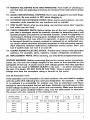
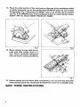
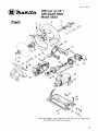
185 mm (744”)
MODEL 5820
Equipped with Electric Brake
INSTRUCTION MANUAL
‘ION
SPECIFI CAT I0 NS
Max. cutting capacities
Blade
diameter
185 m m
(7-114”)
1
64 mm
12-112”)
I
43mm
(1.518“)
No load speed
(RPMI
I
4,000
1
Overall
length
I
Net
weight
285 m m
111-114”)
1
3.5 k g
(7.7 Ibs)
* Manufacturer reserves the right t o change specifications without notice.
Note: Specifications may differ from country to country.
IMPORTANT
SAFETY INSTRUCTIONS
(For All Tools)
WARNING: WHEN USING ELECTRIC TOOLS, BASIC SAFETY PRECAUTIONS SHOULD ALWAYS BE FOLLOWED TO
REDUCE THE RISK OF FIRE, ELECTRIC SHOCK, AND PERSONAL INJURY, INCLUDING THE FOLLOWING:
READ ALL INSTRUCTIONS.
1. KEEP WORK AREA CLEAN. Cluttered areas and benches invite injuries.
2. CONSIDER WORK AREA ENVIRONMENT. Don't use power tools in damp
or wet locations. Keep work area well lit. Don't expose power tools t o rain.
Don't use tool in presence of flammable liquids or gases.
3. KEEP CHILDREN AWAY. All visitors should be kept away from work area.
Don't let visitors contact tool or extension cord.
4.STORE IDLE TOOLS. When not in use, tools should be stored in dry, and high
or locked-up place - out of reach of children.
5 . DON'T FORCE TOOL. It will do the job better and safer at the rate for which
it was intended.
6 . USE RIGHT TOOL. Don't force small tool or attachment t o do the job of a
heavy-duty tool. Don't use tool for purpose not intended.
7 . DRESS PROPERLY. Don't wear loose clothing or jewelry. They can be caught
in moving parts. Rubber gloves and non-skid footwear are recommended
when working outdoors. Wear protective hair covering t o contain long hair.
8. USE SAFETY GLASSES. Also use face or dust mask if cutting operation is
dusty.
9. DON'T ABUSE CORD. Never carry tool by cord or yank it t o disconnect from
receptacle. Keep cord from heat, oil, and sharp edges.
I O . SECURE WORK. Use clamps or a vise t o hold work. It's safer than using
your hand and it frees both hands t o operate tool.
11. DON'T OVERREACH. Keep proper footing and balance at all times.
12. MAINTAIN TOOLS WITH CARE. Keep tools sharp and clean for better and
safer performance. Follow instructions for lubricating and changing accessories. Inspect tool cords periodically and if damaged, have repaired by authorized service facility. Inspect extension cords periodically and replace if
damaged. Keep handles dry, clean, and free from oil and grease.
13. DISCONNECT TOOLS. When not in use, before servicing, and when changing accessories, such as blades, bits, cutters.
2
14. REMOVE ADJUSTING KEYS AND WRENCHES. Form habit of checking t o
see that keys and adjusting wrenches are removed from tool before turning
it on.
15. AVOID UNINTENTIONALSTARTING. Don't carry plugged-in tool with finger
on switch. Be sure switch is OFF when plugging in.
16. OUTDOOR USE EXTENSION CORDS. When tool is used outdoors, use only
extension cords intended for use outdoors and so marked.
17. STAY ALERT. Watch what you are doing, use common sense. Don't operate
tool when you are tired.
18. CHECK DAMAGED PARTS. Before further use of the tool, a guard or other
part that is damaged should be carefully checked t o determine that it will
operate properly and perform its intended function. Check for alignment of
moving parts, binding of moving parts, breakage of parts, mounting, and any
other conditions that may affect its operation. A guard or other part that
is damaged should be properly repaired or replaced by an authorized service center unless otherwise indicated elsewhere in this instruction manual.
Have defective switches replaced by authorized service center. Don't use
tool if switch does not turn it on and off.
19. GUARD AGAINST ELECTRIC SHOCK. Prevent body contact with grounded
surfaces. For example; pipes, radiators, ranges, refrigerator enclosures.
20. REPLACEMENT PARTS. When servicing, use only identical replacement parts.
VOLTAGE WARNING: Before connecting the tool t o a power source (receptacle,
outlet, etc.) be sure the voltage supplied is the same as that specified on the
nameplate of the tool. A power source with voltage greater than that specified
for the tool can result in SERIOUS INJURY t o the user - as well as damage t o
the tool. If in doubt, DO NOT PLUG IN THE TOOL. Using a power source with
voltage less than the nameplate rating is harmful t o the motor.
Ampere rating
(on nameplate)
02.00
2.10
3.40
3.50 5.00
5.10
7.00
-
7.10 12.00
12.10
16.00
~
Wire Size (American Wire Gauge)
Ext. Cable Length
25 Ft.
50 Ft.
75 Ft.
100 Ft.
150 Ft.
-
18
18
18
18
16
18
18
18
16
14
18
18
16
14
12
18
16
14
12
12
16
14
12
10
~
14
12
10
~
3
ADDITIONAL SAFETY RULES
1. Wear hearing protection.
2. Keep Guards In Place and In Working Order.
Never wedge or tie lower guard open. Check operation of lower guard before each use. Don't use if lower guard does not close briskly over saw blade.
CAUTION: If saw is dropped, lower guard may be bent, restricting full return.
3. Keep Blades Clean and Sharp.
Sharp blades minimize stalling and kickback.
4. DANGER: Keep Hands Away From Cutting Area.
Keep hands away from blades. Don't reach underneath work while blade
is rotating. Don't attempt t o remove cut material when blade is moving.
CAUTION: Blades coast after turn off.
5. Support Large Panels.
Large panels must be supported as
shown in Fig. 1to minimize the risk
of blade pinching and kickback.
When cutting operation requires
the resting of the saw on the work
piece, the saw shall be rested on
the larger portion and the smaller
piece cut off.
To avoid kickback, do support board
or panel near the cut.
Fig.
Don't support board or panel away
from the cut.
Fig. '
6. Use Rip Fence.
Always use a fence or straight edge guide when ripping.
7. Guard Against Kickback.
Kickback occurs when the saw stalls rapidly and is driven back towards the
operator. Release switch immediately if blade binds or saw stalls. Keep blades
sharp. Support large panels as shown in Fig. 1. Use fence or straight edge
guide when ripping. Don't force tool. Stay alert exercise control. Don't remove saw from work during a cut while the blade is moving.
4
NEVER place your hand or fingers
behind the saw. If kickback occurs, the saw could easily jump
backwards over your hand, possibly causing severe injury.
Fig.
:
8. Lower Guard. Raise lower guard with the retracting handle.
9. Adjustments. Before cutting be sure depth and bevel adjustments are tight.
IO. Use Only Correct Blades In Mounting. Don’t use blades with incorrect size
holes. Never use defective or incorrect blade washers or bolts.
11. Avoid Cutting Nails. Inspect for and remove all nails from lumber before
cutting.
12. When operating the saw, keep the
cord away from the cutting area
and position it so that it will not be
caught on the workpiece during
the cutting operation.
Operate with proper hand support,
proper workpiece support, and
supply cord routing away from the
work area.
A typical illustration of proper hand
support, workpiece support, and
supply cord routing.
Fig. 1
WARNING:
It is important t o support the workpiece properly and t o hold the saw firmly
t o prevent loss of control which could cause personal injury. Fig. 4 illustrates
typical hand support of the saw.
5
13. Place the wider portion of the saw base on that part of the workpiece which
is solidly supported, not on the section that will fall off when the cut is made.
As examples, Fig. 5 illustrates the RIGHT way t o cut off the end of a board,
and Fig. 6 the WRONG way. If the workpiece is short or small, clamp it down.
DON'T TRY TO HOLD SHORT PIECES BY HAND!
Fig.
Fig.
14. Never attempt t o saw with the cii
cular saw held upside down in a
vise. This is extremely dangerous
and can lead t o serious accidents.
I
I
Fig. i
15. Before setting the tool down after completing a cut, be sure that the lower
(telescoping) guard has closed and the blade has come to a complete stop.
SAVE THESE INSTRUCTIONS.
6
Installing or removing saw blade
CAUTION :
Always be sure that the tool is switched off and unplugged before installing or removing
the blade.
The saw blade ha5 not been mounted on
the saw a t the factory, but has been packed
separately in the same carton. To install
the blade, carefully follow the procedure
outlined below :
Hold the outer flange with the wrench and
loosen the hex bolt counterclockwise with
the socket wrench. Then remove the hex
bolt and outer flange.
Outer flange
\
Inner flange
I
\
’-
Fig. 8
Place the saw blade on the shaft (arbor),
making sure that the blade teeth point forward in the same direction as the tool rotation (the arrow on the blade should point
in the same direction as the arrow on the
tool). Replace the outer flange and hex
bolt over the blade and TIGHTEN THE
HEX BOLT SECURELY in a CLOCKWISE
direction.
I
Fig. S
CAUTION :
.Use only the Makita wrench and socket
wrench to install or remove the blade.
the recessed side of the inner
flange on the blade side when mounting.
position
I
Fig. 1(
To remove the blade, follow the installation procedure in reverse.
7
Adjusting depth of cut
Loosen the wing nut on the depth guide
and move the base up or down. At the
desired depth of cut, secure the base by
tightening the wing nut.
CAUTION :
0 Use a shallow depth of cut when cutting thin workpiece for cleaner, safer cuts.
0
After adjusting the depth of cut, always tighten the wing nut securely.
Sighting
For straight cuts, align the right notch in
the top guide with !our cutting line on the
workpiece. For 45 bevel cuts, align the
left notch with it.
For 45"
bevel cuts
1
cFuq:straight
Base plate
I
I
Fig. 13
Switch action
To prevent the trigger from being accidentally pulled, a lock-off button i s provided
as a safety feature.
To start the tool, press in the lock-off
button and pull the trigger. Release the
trigger to stop.
Fig. 14
CAUTION :
Before plugging in the tool, always check to see that the trigger switch actuates properly
and returns to the "OFF" position when released.
8
Operation
Grasp the rear handle with your right hand,
the front grip with your left. Set the base
plate on the workpiece to be cut without
the blade making any contact. Then turn
the tool on and wait until the blade attains
full speed. Now simply move the tool forward over the workpiece surface, keeping
it flat and advancing smoothly until the
sawing is completed. To get clean cuts,
keep your sawing line straight and your
speed of advance uniform.
Guide rule
The handy guide rule allows you to do
extra-accurate straight cuts. Simply slide
the guide rule up snugly against the side of
the workpiece and secure it in position
with the wing bolt on the front of the base.
I t also makes repeated cuts of uniform
width possible.
MA1NTENANCE
CAUTION :
Always be sure that the tool i s switched off and unplugged before attempting to perform
inspection or maintenance.
The tool will stop when the carbon brushes wear to a certain length.
When this occurs, both carbon brushes should be replaced.
To maintain product SAFETY and RELlABlLITY, repairs, carbon brush inspection
and replacement, any other maintenance or adjustment should be performed by Makita
Authorized or Factory Service Centers, always using Makita replacement parts.
9
ACCESSORI ES
CAUTION :
These accessories or attachments are recommended for use with your Makita tool specified in this
manual. The use of any other accessories or attachments might present a risk of injury t o persons.
The accessories or attachments should be used only in the proper and intended manner.
0
Guide rule
Part No. 164095-8
0
Socket wrench 9
Part No. 782209-3
0
Chisel tooth combination saw blade
0
Wrench 9
Part No. 781401 - 8
Part
NO.
792239-6
0
Carbide-tipped saw blade
Faster, smoother, longer sawing
without blade sharpening.
Cuts wood, dry wall, plastic
hard wood, etc.
10
~~
Part No.
I
Diameter
I
Hole
diameter
185
(7-114,,)
518“
I Dc:GTer I
Hole
diameter
1
No.
teeth
20
I
No.
teeth
Feb.-O6-'89
US
@mm
CIRCULAR SAW
185 mm (7-1/4")
-
Model 5820
Note: The switch, noise suppressor and other part configurations
may differ from country to country.
11
MODEL 5 8 2 0
,$&,
/LM
r
Feb-06-'89
""df &
!,
DESCRIPTION
MACHINE
2
1
1
3
1
4
5
6
1
1
1
1
I
8
9
10
11
1
1
1
12
1
1
13
14
15
16
lJ
18
19
20
21
4
1
1
1
1
1
1
1
1
22
23
1
24
25
26
27
1
1
2
1
8
-
DESCRIPTION
MACHINE
~
1
US
~
Wing Nut M6
Spring Washer 6
Tension Spring 4
Cap Square Neck Bolt M6x20
29
1
30
3
3
Blade Case
33
1
Woodruff Key 4
Plane Bearing 8
Thin Washer 8
Helical Gear 50
Sleeve 1 2
Ball Bearing 6201LLB
34
35
36
1
1
1
1
31
32
1
37
38
1
39
1
41
42
43
44
45
46
47
48
49
1
Spindle
Pan Head Screw M4x22 lWith Washer]
Rubber Sleeve 6
Pan Head Screw M6x20
Flat Washer 38
Safety cover
Retaining Ring S-38
Inner Flange 4 0
Outer Flange 4 0
Hex Flange Head Bolt M6x17
Cord
Cord Guard
Strain Relief
Pan Head Screw M4xlB lWith Washer]
Motor Housing Set IWith Item 461
T a o ~ i n aScrew BT 4x40
1
1
1
2
1
1
1
1
50
1
51
52
53
54
55
1
1
-
1
1
1
-
Switch
Pan Head Screw M4x28 lWith Washer1
Pen Head Screw M5x35 lWith Washer1
Handle Set IWith Item 351
Terminal Base Complete
Rubber Pin 4
Handle Set IWith Item 321
0 Ring 30
Ball Bearing 6200LLB
Fan 86
ARMATURE ASSEMBLY
IWith Item 37 - 3 9 & 411
Ball Bearing 608LB
Flat Washer 1 4
0 Ring 1 8
Field
Carbon Brush
Motor Housing Set lWith Item 261
Name Plate
Cap Square Neck Bolt M6x20
Wing Bolt M6x 1 5
Comprsrslon S p m g 7
Wing Nut M6
Spring Washer 6
Flat Washer 6
Base
S ~ m Pin
a 6-36
Note The switch and other part specifications may differ from country to country.
MAKITA LIMITEDONE YEAR WARRANTY
Warranty Policy
Every Makita tool is thoroughly inspected and tested before leaving the factory. It is warranted t o
be free of defects from workmanship and matenals for the period of ONE YEAR from the date of
original purchase. Should any trouble develop during this one-yearperiod, return the COMPLETE
tool, freight prepaid, to one of Makita's Factory or Authorized Service Centers. If inspection shows
the trouble is caused by defective workmanship or matenal, Makita will repair (or at our option,
replace) without charge
This Warranty does not apply where:
repurr have been made or attempted by others:
repairs are required because of normal wear and tear
The tool has been abused, misused o r improperly maintained:
alterations have been made to the tool.
.
IN NO EVENT SHALL MAKITA BE LIABLE FOR ANY INDIRECT. INCIDENTAL OR CONSEQUENTIAL DAMAGES FROM THE SALE OR USE O F THE PRODUCT. THIS DISCLAIMER
APPLIES BOTH DURING AND AFTER THE TERM OF THIS WARRANTY.
UAKITA DISCLAIMS LIABILITY FOR ANY IMPLII'D WARRANTIt S. INCLUDING IMPLIED
WARRAVTILS OF "MERCHANTABILITY" AND 'FITNESS FOR A SPECIFIC PL'RPOSE.'
AFTER THE ONL-Y FAR TERM O F THIS WARRANTY
Tlur Warranty gwec you s p m f i c legs1 nghtr and you may also hive other nghtr uhlrh vary from
stale 10 state Some slates do not allow rh; exelusion or hmrtalion of incrdcntal or consequential
damages IO the above lunilatron or cxclucron may no1 apply to you Some slates do not allou
limiralrdn on h o u long an implied warranty lasts, so the above Irmllation may not apply lo you
Flrrtkirwnnuh,Ltd.
11-8.3-chome, Sumiyoshi-cho. Anjo, Aichi 446, Japan
883691-062
PRINTED IN JAPAN
1989 - 3 - N