1
Wireless LAN Adapter
NZ2WL-US/NZ2WL-EU/
NZ2WL-CN/NZ2WL-KR/
NZ2WL-TW
User’s Manual
Powered by CONTEC
This product was jointly developed and manufactured by Mitsubishi and
CONTEC.
Note that some of the warranty on this product differs from that on other
products (MELSEC-Q or MELSEC-L series).
(Refer to "Terms of Warranty”.)
MODEL
NZ2WL-U-E
MODEL
13JZ55
CODE
IB(NA)-0800471ENG-C(1111)MEE
© 2011 MITSUBISHI ELECTRIC CORPORATION
Precautions regarding Warranty and Specifications
This product was jointly developed and manufactured by Mitsubishi and CONTEC.
Note that there are some precautions regarding warranty and specifications of the product.
< Warranty >
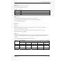
The gratis warranty term of the product shall be for one (1) year after the date of delivery or for eighteen (18)
months after manufacturing, whichever is less.
-
The onerous repair term after discontinuation of production shall be for six (6) years.
-
Mitsubishi shall mainly replace products that need repair.
-
It may take some time to respond to the problem or repair the product depending on the condition and timing.
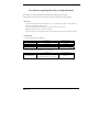
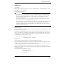
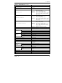
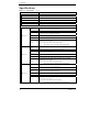
< Specifications >
-
General specifications are different.
NZ2WL-xxx
-
MELSEC-Q Series
Operating ambient temperature
0 to 50°C
0 to 55°C
Operating ambient humidity
10 to 90%RH
5 to 95%RH
Storage ambient temperature
-10 to 60°C
-25 to 75°C
Storage ambient humidity
10 to 90%RH
5 to 95%RH
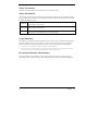
R&TTE standards that are applicable to the products differ.
NZ2WL-EU
R&TTE standards
NZ2WL - xxx
EN300 328/EN301 893/EN301 489-1,-17/
EN55022/EN55024/EN61000-3-2,-3-3/EN60950-1
MELSEC-Q Series
EN61131-2
i
Safety Precautions
Review the following definitions and precautions to use the product safely.
Safety Information
This document provides safety information using the following symbols to prevent accidents resulting
in injury or death and the destruction of equipment and resources. Review the meanings of these labels
to operate the equipment safely.
DANGER
DANGER indicates an imminently hazardous situation which, if not avoided, will
result in death or serious injury.
WARNING
WARNING indicates a potentially hazardous situation which, if not avoided, could
result in death or serious injury.
CAUTION
CAUTION indicates a potentially hazardous situation which, if not avoided, may
result in minor or moderate injury or in property damage.
Usage limitation
This product has not been developed or manufactured to be used in systems including equipment which
is directly related to human lives or equipment*1 which involves human safety and may significantly
affect the maintenance of public functions*2. Therefore, do not use the product for such purposes.
*1:
Medical devices such as life-support equipment and devices used in an operating theater.
*2:
Main control systems at nuclear power stations, safety maintenance systems at nuclear facilities, other important safety-related
systems, operation control systems within group transport systems, air-traffic control systems, etc.
Precautions Related to Maintenance
Clean this product by wiping lightly with a soft cloth moistened with water or a neutral detergent.
Avoid using benzene, thinners or other volatile solutions that may cause deformation or discoloration.
ii
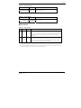
NZ2WL - xxx
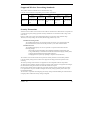
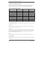
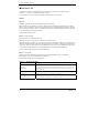
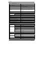
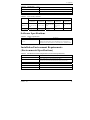
Supported Wireless Networking Standards
This product conforms with IEEE 802.11a and IEEE 802.11b/g.
It can be set to the channels corresponding to the countries listed below.
Channel*1
Standard
U.S.A.
Europe
China
Korea
Taiwan
(NZ2WL-US)
(NZ2WL-EU)
(NZ2WL-CN)
(NZ2WL-KR)
(NZ2WL-TW)
36, 40, 44, 48,
IEEE802.11a
149, 153, 157, 161, 36, 40, 44, 48ch
165ch
IEEE802.11b/g
1-11ch
1-13ch
149, 153, 157, 161,
165ch
1-13ch
36, 40, 44,
149, 153, 157,
161ch
1-13ch
149, 153, 157, 161,
165ch
1-11ch
*1 The channels of this product can be changed only among the same models.
Security Precautions
Wireless LAN uses radio waves instead of LAN cables to send and receive data between a computer and
a wireless access point, making it possible to freely establish a LAN connection within a range of the
radio waves.
However, radio waves can be received through obstacles, such as walls, when within the range.
Therefore, if security settings are not made, the following problems may occur.
Unauthorized viewing of data
An unauthorized third party can intercept the radio waves and view e-mail messages and
personal information, such as user ID and password or your credit card information.
Unauthorized access
An unauthorized third party can access a personal or corporate network and cause the
following damage:
- Intercepting personal information and confidential information (information leak)
- Using a false identity to communicate and disclose information illegally (identity theft)
- Changing and transmitting intercepted data (tampering)
- Damaging data and systems by spreading a computer virus (destruction)
The wireless LAN card and wireless access point have security features to counter these problems.
Using the security settings of the wireless LAN equipment can help prevent these problems from
occurring.
The security settings of the wireless LAN equipment are not configured at the time of purchase.
To reduce security problems, configure all security settings of the wireless LAN equipment according to
the manual before using the wireless LAN card and wireless access point.
Please be aware that the security settings do not provide complete security protection due to wireless
LAN specifications. If you are unable to configure the security settings yourself, please contact your
local authorized dealer.
The customer is responsible for configuring the security settings and understanding the risks inherent in
using the product without the security settings configured.
NZ2WL - xxx
iii
Handling Precautions
WARNING
-
Do not use the product where it is exposed to flammable or corrosive gas. Failure to do so may result in an
explosion, fire, electric shock, or failure.
-
The product could be very hot in the operation. Please do not touch with hands or body. It may cause burns.
-
To avoid electric shock, please do not touch the system with a wet hand.
-
As this product contains precision electronic components, do not use or store it in a place subject to shock or
vibration. Doing so may cause malfunction, heat generation, fault, or damage.
-
Ground the FG terminal to a protective ground conductor.
-
Place the cables in a duct or clamp them. If not, dangling cable may swing or inadvertently be pulled, resulting in
damage to the product or cables or malfunction due to poor contact.
-
When disconnecting the communication cable or power cable from the product, do not pull the cable by the cable
part.
-
Correctly connect the power cables to the product.
-
Do not install control lines or communication cables together with the main circuit lines or power cables. Keep a
distance of 100mm or more between them. Failure to do so may result in malfunction due to noise.
-
Prevent foreign matter such as dust or wire chips from entering the product. Such foreign matter can cause a fire,
failure, or malfunction.
-
Do not use or store the product in a hot or cold place, or in a place that is subject to severe temperature changes.
Doing so may cause malfunction, heat generation, fault, or damage.
-
Do not use or store the product in a place subject to direct sunlight or near a heating device, such as a stove. And
do not use or store the product near equipment generating a strong magnetic field or radio waves. Doing so may
cause malfunction, heat generation, fault, or damage.
-
Do not use or store this product in the presence of chemicals.
-
Do not use this product in extremely humid or dusty locations.
It is extremely dangerous to use this product if the interior contains water or any other fluid or conductive dust.
-
If you notice abnormal odor or overheating, please disconnect the power cable immediately.
-
If you find a fault or other abnormality (bad smell or excessive heat), unplug the power terminal connector and
then contact your local authorized dealer.
-
Do not open the product casing. Mitsubishi will disclaim any responsibility for products whose casing has been
opened.
-
Do not modify the product. Mitsubishi will bear no responsibility for any problems, etc., resulting from modifying the
product.
-
To clean this product, gently wipe it with a soft cloth soaked with water or a neutral detergent. Do not use
benzene, paint thinner, or other volatile solvents as they can cause the coating to discolor or peel off.
-
The specifications of this product are subject to change without notice because of function addition and quality
improvement.
Even when using the product continuously, read the user's manual and check the contents.
-
If you move or transfer the product, make sure provide this manual with the product.
-
Regardless of the foregoing statements, Mitsubishi is not liable for any damages whatsoever (including damages
for loss of business profits) arising out of the use or inability to use this Mitsubishi product or the information
contained herein.
-
This product is equipped with a fuse (current rating: 2A) to prevent burning of the unit from overvoltage. (This
fuse is not user serviceable.) See the warranty for information on coverage during fuse interruptions.
iv
CAUTION
NZ2WL - xxx
-
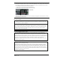
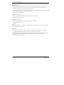
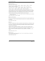
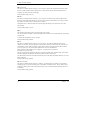
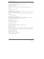
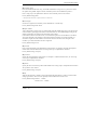
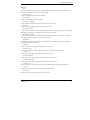
FCC PART15, R&TTE Directive, NCC Certification addenda (for USA, Europe, and Taiwan only)
The NZ2WL-US , NZ2WL-EU, and NZ2WL-TW comply with FCC PART15, the R&TTE Directive, and the
NCC Certification when used under the following conditions.
-
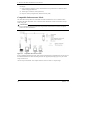
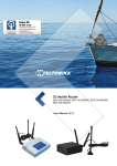
Attach ferrite cores to the power supply line and the FG line.
The following picture shows the ferrite cores attached to the cable.
2cm from the EUT
6cm from the EUT
Attach ferrite cores to the FG line (2cm from the EUT) and the power supply line (6cm from the EUT), and turn
the cable three times (wind it twice).
FCC Part 15 Notice
FCC WARNING
Changes or modifications not expressly approved by the party responsible for compliance could void the
user’s authority to operate the equipment.
This transmitter must not be co-located or operated in conjunction with any other antenna or transmitter.
This equipment complies with FCC radiation exposure limits set forth for a controlled environment and meets
the FCC radio frequency (RF) Exposure Guidelines in Supplement C to OET65. This equipment should be
installed and operated keeping the radiator at least 20cm or more away from person’s body (excluding
extremities: hands, wrists, feet and ankles).
Ferrite cores must be used with the power supply line and FG line to suppress radio frequency interference.
FCC Part 15 Subpart B class A Notice
Note: This equipment has been tested and found to comply with the limits for a Class A digital device,
pursuant to part 15 of the FCC Rules. These limits are designed to provide reasonable protection against
harmful interference when the equipment is operated in a commercial environment. This equipment generates,
uses, and can radiate radio frequency energy and, if not installed and used in accordance with the instruction
manual, may cause harmful interference to radio communications. Operation of this equipment in a
residential area is likely to cause harmful interference in which case the user will be required to correct the
interference at his own expense.
FCC Part 15 Subpart E Notice
Operations in the 5.15-5.25GHz band are restricted to indoor usage only.
Compliance with FCC requirement 15.407(c)
Data transmission is always initiated by software, which is then passed down through the MAC, through the
digital and analog baseband, and finally to the RF chip. Several special packets are initiated by the MAC.
These are the only ways the digital baseband portion will turn on the RF transmitter, which it then turns off at
the end of the packet. Therefore, the transmitter will be on only while one of the aforementioned packets is
being transmitted. In other words, this device automatically discontinue transmission in case of either absence
of information to transmit or operational failure.
Frequecncy tolerance:±30ppm
NZ2WL - xxx
v
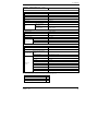
Connection to MELSEC Series Equipment
The NZ2WL Series can be connected to various programmable controllers and display units.
Connectable Equipment
The following MELSEC Series equipment can be connected. *1
Type
Programmable
Controller
HMI
Motion
Controller
CNC
Software
Model
MELSEC-Q Series Ethernet Interface Module (for 10BASE-T/100BASE-TX) *2
CC-Link IE Field Network Ethernet Adapter Module *3
Industrial Switching HUB
MELSEC-Q Series CPU Module (with Built-in Ethernet)
MELSEC-L Series CPU Module
C Controller Module
GOT1000 Series (with Built-in Ethernet)
GOT1000 Series Ethernet Communication Unit
Motion Controller Q Series Motion CPU Module
Motion Controller Q Series Motion CPU Module (for the iQ Platform)
Motion Controller Q Series Stand-Alone Motion Controller
MITSUBISHI CNC M700/M70 Series
MITSUBISHI CNC M700V/M70V Series
MITSUBISHI CNC C70 Series
GX Works2
MX Component
MX Sheet
LCPU Logging Configuration Tool
GX LogViewer
GX IEC Developer
PX Developer
PX Developer Monitor Tool
C Controller Module Setting / Monitoring Tool
CW Workbench
GT Works3
MT Works2
CNC Remote Operating Tool (NC Monitor/NC Explorer)
*1 The manuals of some of these products may indicate that operations cannot be guaranteed when connected using a
wireless network other than that using this wireless LAN equipment. Before using this product, please read "Note on
Connections" on the next page.
*2 Before using this product with Ethernet interface modules, please read "Note on Connection with Ethernet Interface
Module” on the next page.
*3 The NZ2WL series can be connected only to the Ethernet part of this module. The NZ2WL series cannot be connected to
the CC-Link IE Field Network part of this module.
vi
NZ2WL - xxx
Note on Connections
CAUTION
-
-
-
Do not use this product for applications that must transmit or update data regularly or within a
given time period, such as the cyclic transmission of a programmable controller. Transmission
delays cannot be obtained through calculations for Ethernet communications using this product.
Use this product with the access point and station in visual range of each other (so that the antenna
on one device is visible from the antenna on the other device).
During an Ethernet connection using wireless LAN, packets may be lost due to the peripheral
environment and equipment location, and the connection may not be as stable as with a wired
Ethernet connection. Be sure to check operations when using this product. Packets may be
frequently lost especially during broadcasts. In this case, use a user application or use UDP or TCP
with a specified IP address for the client.
If the timer value set for the MELSEC Series equipment connected to this product is large, it may
take time to detect the loss of packets, and communications may appear to have stopped.*1 In this
case, changing the timer value may fix the problem.
Do not directly connect a MELSEC-Q Series CPU module (with Built-in Ethernet) or a
MELSEC-L Series CPU module to an Ethernet port on a MELSOFT product by wireless LAN
connection.
For additional restrictions and notes on using a wireless LAN connection, see the manual of the
MELSEC products to which this product is connected.
This product cannot be directly connected to a CC-Link IE Field Network. A wired Ethernet
connection must be made using an optional CC-Link IE Field Network Ethernet adapter module.
If a problem occurs, but there is nothing wrong with the settings or usage of MELSEC products
connected to this product or the Ethernet wire, there may be a problem with the setup or settings of
this product. Refer to "Chapter 7 Troubleshooting" and check the operations of this product. You
can also refer to the user's manuals of the MELSEC products connected to this product.
*1 For example, the default value of the response monitoring timer of the Ethernet Interface Module is 30 seconds, so it
takes 30 seconds to detect packet losses.
Note on Connection with Ethernet Interface Module
-
-
When connecting this product with an Ethernet interface module, the COM.ERR.LED of the
Ethernet interface module may turn on (error code: C04BH, etc.) due to some reasons such as
packet loss. Communication can be performed with the COM.ERR.LED turned on. However,
check carefully that the system works as expected.
For how to turn off the COM.ERR.LED, refer to "Q Corresponding Ethernet Interface Module
User's Manual (Basic)".
When the COM.ERR.LED frequently turns on, the following operations may reduce the frequency:
- Use TCP on the connection.
- Enable TCP segmentation*2.
To enable TCP segmentation, set 5B4H to the TCP Maximum Segment Transmission setting area
(address: 1EH) and execute reinitialization.
For reinitialization, refer to "Q Corresponding Ethernet Interface Module User's Manual (Basic)."
*2 The TCP Maximum Segment Transmission setting area can be configured only for the Ethernet interface modules
(QJ71E71-100) with function version B or later, whose first five digits of the serial number are 05051 or later.
When the setting is changed to "Enable TCP Maximum Segment Size Option transmission, there are restrictions on
combination with the MELSOFT products. Refer to "Q Corresponding Ethernet Interface Module User's Manual
(Basic)".
NZ2WL - xxx
vii
CONDITIONS OF USE FOR THE PRODUCT
(1)
(2)
viii
Mitsubishi programmable controller ("the PRODUCT") shall be used in conditions;
i) where any problem, fault or failure occurring in the PRODUCT, if any, shall not lead to any
major or serious accident; and
ii) where the backup and fail-safe function are systematically or automatically provided outside of
the PRODUCT for the case of any problem, fault or failure occurring in the PRODUCT.
The PRODUCT has been designed and manufactured for the purpose of being used in general
industries.
MITSUBISHI SHALL HAVE NO RESPONSIBILITY OR LIABILITY (INCLUDING, BUT
NOT LIMITED TO ANY AND ALL RESPONSIBILITY OR LIABILITY BASED ON
CONTRACT, WARRANTY, TORT, PRODUCT LIABILITY) FOR ANY INJURY OR DEATH
TO PERSONS OR LOSS OR DAMAGE TO PROPERTY CAUSED BY the PRODUCT THAT
ARE OPERATED OR USED IN APPLICATION NOT INTENDED OR EXCLUDED BY
INSTRUCTIONS, PRECAUTIONS, OR WARNING CONTAINED IN MITSUBISHI'S USER,
INSTRUCTION AND/OR SAFETY MANUALS, TECHNICAL BULLETINS AND
GUIDELINES FOR the PRODUCT.
("Prohibited Application")
Prohibited Applications include, but not limited to, the use of the PRODUCT in;
- Nuclear Power Plants and any other power plants operated by Power companies, and/or any
other cases in which the public could be affected if any problem or fault occurs in the
PRODUCT.
- Railway companies or Public service purposes, and/or any other cases in which establishment
of a special quality assurance system is required by the Purchaser or End User.
- Aircraft or Aerospace, Medical applications, Train equipment, transport equipment such as
Elevator and Escalator, Incineration and Fuel devices, Vehicles, Manned transportation,
Equipment for Recreation and Amusement, and Safety devices, handling of Nuclear or
Hazardous Materials or Chemicals, Mining and Drilling, and/or other applications where there
is a significant risk of injury to the public or property.
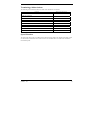
NZ2WL - xxx
Terminology/Abbreviations
The following terms and abbreviations are used in this manual for convenience.
Full term
All five NZ2WL models (NZ2WL-US, NZ2WL-EU, NZ2WL-CN,
Term used in this manual
NZ2WL-xxx
NZ2WL-KR, NZ2WL-TW)
NZ2WL-US (for U.S.A.)
US
NZ2WL-EU (for Europe)
EU
NZ2WL-CN (for China)
CN
NZ2WL-KR (for Korea)
KR
NZ2WL-TW (for Taiwan)
TW
Access point only supported
(AP only)
Station only supported
(ST only)
A device with the wireless function
Wireless terminal
Personal computer
PC
Speed Notation
The link speed values (such as 54 Mbps) of the transmission rate used in this manual and setting screens
are the theoretical maximum values of the wireless LAN standard and do not indicate the actual data
transmission speed.
NZ2WL - xxx
ix
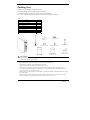
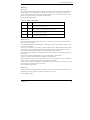
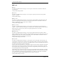
Packing List
Thank you for purchasing this Mitsubishi product.
The product package should contain the items listed below.
Use the following list to confirm the contents of the product package.
If you discover any damaged or missing item, contact your local authorized dealer.
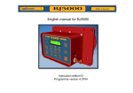
Contents
Name
Main unit (NZ2WL-xxx)
Pcs.
1
Antenna, rubber cap for antenna
2
User’s Manual
1
Power terminal connector
1
Retention bracket
1
Mounting bracket
1
Bracket screw M3 x 6
3
Setup manual (CN,KR,TW only)
1
Ferrite core (US,EU,TW only)
2
Rubber cap for
antenna × 2
Antenna x 2
Retention bracket
Power terminal
Bracket screw M3 x 6 × 3
Main unit
User’s Manual
CAUTION
Setup manual
(CN, KR, TW only)
Mounting bracket
Ferrite core × 2
(US, EU, TW only)
To operate this product, a power supply (12-24VDC±5%) is required separately. For power supply, see Chapter 2,
Part Names and Settings, “Power Supply”.
-
x
This document, in whole or in part, may not be reproduced without permission.
This document is subject to change without notice at any time.
While we are doing our best to ensure this document has no error,
should you have any questions or find any omissions or similar, consult your local authorized dealer.
MS, Microsoft, Windows, Windows NT, and MS-DOS are registered trademarks or trademarks of Microsoft
Corporation in the U.S.A. and other countries.
Mozilla, Firefox, and the Firefox logo are trademarks or registered trademarks of Mozilla Foundation in the U.S.
and other countries.
All other company names and products used in this manual are trademarks or registered trademarks of their
respective companies. This manual does not use the symbols such as ™, ®, and ©.
NZ2WL - xxx
Table of Contents
Packing List......................................................................................................................................... x
1.
BEFORE USING THE PRODUCT
1
Overview............................................................................................................................................. 1
Features ........................................................................................................................................ 1
Environment ................................................................................................................................. 3
Inspection ..................................................................................................................................... 3
Storage ......................................................................................................................................... 3
Disposal........................................................................................................................................ 3
2.
SETUP
4
Part Names and Functions................................................................................................................... 4
LED display ................................................................................................................................. 4
DIP switches................................................................................................................................. 5
Connectors.................................................................................................................................... 6
Checking the Network Addresses ....................................................................................................... 6
Attaching the Antennas ....................................................................................................................... 7
FCC PART15, R&TTE Directive, NCC Certification addenda (for USA, Europe, and Taiwan only) . 7
Power Supply ...................................................................................................................................... 8
Grounding the NZ2WL ....................................................................................................................... 9
Installation........................................................................................................................................... 9
Using Mounting Brackets............................................................................................................. 9
Wired LAN Connection .................................................................................................................... 10
3.
CONNECTING TO DEVICES AND SETUP METHODS
11
Setup Methods................................................................................................................................... 11
Preparation before Setup ................................................................................................................... 11
Setup Using Web Browser ................................................................................................................ 12
Setting the Browser .................................................................................................................... 12
Connecting to This Product Using Web Browser ...................................................................... 13
Setup Using Web Browser ......................................................................................................... 14
Setup Using TELNET ....................................................................................................................... 15
Connecting to the Product Using TELNET................................................................................ 15
Setup Using TELNET ................................................................................................................ 17
TELNET Key Operation ............................................................................................................ 18
NZ2WL - xxx
xi
4.
WIRELESS LINK MODE AND WIRELESS LAN FUNCTION
19
Wireless Link Mode .......................................................................................................................... 19
Standard Infrastructure Mode..................................................................................................... 19
Compatible Infrastructure Mode ................................................................................................ 20
Advanced Infrastructure Mode................................................................................................... 21
Comparison of Main Functions .................................................................................................. 22
Installation in a Network ................................................................................................................... 24
Features of the Wireless Network .............................................................................................. 24
Operating Environment and Radio Waves ................................................................................. 25
Constructing a Network.............................................................................................................. 26
5.
SETUP AND STATUS DISPLAY
27
Settings .............................................................................................................................................. 27
◆Basic setting ........................................................................................................................... 27
◆Ethernet .................................................................................................................................. 29
◆Wireless LAN......................................................................................................................... 30
◆IEEE802.1X ........................................................................................................................... 39
◆Extension ................................................................................................................................ 41
◆SNMP ..................................................................................................................................... 44
◆VLAN..................................................................................................................................... 46
◆Log ......................................................................................................................................... 47
Status Display.................................................................................................................................... 48
6.
MAINTENANCE
55
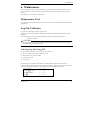
Maintenance Tool.............................................................................................................................. 55
Log File Collection............................................................................................................................ 55
Collecting Log Files Using FTP................................................................................................. 55
Saving a Setting File ......................................................................................................................... 56
Saving Setting File Using FTP ................................................................................................... 56
Restoring the Software Settings ........................................................................................................ 57
Restore Settings Using FTP ....................................................................................................... 57
Time Setting ...................................................................................................................................... 58
Initialization ...................................................................................................................................... 58
Using TELNET .......................................................................................................................... 58
Using a Web Browser................................................................................................................. 59
Using the DIP Switch (INIT) ..................................................................................................... 59
xii
NZ2WL - xxx
7.
TROUBLESHOOTING
60
When Communication Fails.............................................................................................................. 60
Setup Screen Unavailable on Web Browser...................................................................................... 61
When the Product Does Not Start ..................................................................................................... 61
8.
APPENDIX
62
BSHardware Setup ............................................................................................................................ 62
Initial Setting..................................................................................................................................... 62
Specifications .................................................................................................................................... 66
Software Specifications..................................................................................................................... 67
Installation Environment Requirements (Environmental Specifications) ......................................... 67
External Dimensions ......................................................................................................................... 68
Pin Layout of LAN Port .................................................................................................................... 68
WARRANTY.................................................................................................................................... 69
R&TTE Directive.............................................................................................................................. 71
NZ2WL - xxx
xiii
MEMO
xiv
NZ2WL - xxx
1. Before Using the Product
1. Before Using the Product
This chapter provides information you should know before using the product.
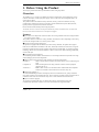
Overview
The NZ2WL-xxx is a wireless LAN adapter that conforms to IEEE 802.11a/b/g standards of various
countries and features a wide input power supply (12 to 24 VDC) and can be configured either as an
access point or station.
This product features WPA2/WPA security functions (AP only), multi-client function (ST only),
extended range (XR) function, Super A/G function, Wireless Distribution System (WDS) function,
Quality of Service (QoS) function, and other functions.
Please read this manual carefully before using the product.
The NZ2WL Series uses a wireless LAN chip set manufactured by Atheros Communications Inc. The main board,
firmware, and the enhanced feature have been developed and equipped.
Features
■The wireless LAN adapter that conforms to IEEE 802.11a/b/g standards and can be configured either
as an access point or station.
This product conforms to IEEE 802.11a/b/g standards, the channel can be set depending on the country,
and it can be configured either as an access point or station.
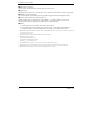
■High-level security features equipped *1
The product is equipped with WPA2/WPA, the latest security standards. The product also supports
IEEE 802.1X authentication in addition to the AES, AES-OCB, and WEP (64/128/152-bit) encryption.
Original encryption functions are also equipped. Those functions include WSL, an original encryption
technology, that can be used with WPA2/WPA or WEP as well as MAC address filtering, ESSID hide,
and ANY ID reject.
■IP tunneling function equipped *2
An IP tunneling function enables communication even at roaming destinations beyond the router range
without changing the network configuration.
■Offering three wireless connection modes according to network configurations
Standard *3
: Mode to use the features unique to the NZ2WL Series, such as IP tunneling and
WSL
Compatible *3
: Mode for heterogeneous use along with other vendors' wireless equipment
supporting Wi-Fi *4
Advanced *3
: Mode to allow wireless LAN terminals both in standard mode and compatible
mode to be connected on the network at the same time (only AP)
■XR function equipped *5
The XR (eXtended Range) function developed by Atheros Communications Inc. greatly extends the
range of the wireless LAN communication area. This is useful for providing a stable connection such as
at locations where radio wave interference may occur or where obstacles create "dead zones".
■Super A/G feature equipped
The product is equipped with super A/G feature that improves communication speed. The
communication speed of the wireless LAN can be increased between supported models.
NZ2WL - xxx
1
1. Before Using the Product
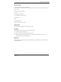
■WDS feature equipped *6
Up to six units can be connected wirelessly between access points.
■QoS support
Bands are secured for specific communication, such as VoIP, and communication quality is guaranteed.
■SNMP agent feature equipped
The feature enables network management using SNMP supported network management software.
■Protect Mode available when using IEEE802.11g
Stable communications are enabled even when IEEE802.11b-compliant products are also used.
Communication speeds are improved for IEEE802.11g-compliant products.
■Others
- Introducing the Diversity Method with a built-in chip antenna.
-
Easy configuration and management using a Web browser. Various maintenance methods are
available according to systems and applications, including FTP commands and TELNET.
*1 WPA2/WPA, IEEE 802.1X authentication, MAC address filtering, ESSID hide, and ANY ID reject can be used only when the product
is configured as an access point.
*2 The IP tunneling function can be used in standard wireless connection mode.
*3 The official names are as follows:
Standard ••• Standard Infrastructure
Compatible ••• Compatible Infrastructure
Advanced ••• Advanced Infrastructure
*4 Compatible mode does not guarantee inter-connectivity with other vendors' Wi-Fi products.
*5 The XR feature can be used only when both of the access point and station in the wireless LAN support the XR feature.
*6 The WDS function is available only when the product is configured as an access point.
2
NZ2WL - xxx
1. Before Using the Product
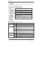
Environment
Use this product in the following environment.
If used under environmental conditions exceeding these ranges, the board may overheat, malfunction, or
cause a failure.
Operating ambient temperature
0 - 50ºC
Operating ambient humidity
10 - 90%RH (No condensation)
Corrosive gases
None
Floating dust particles
Small amounts (non excessive)
Inspection
Inspect the product periodically as follows to use it safely.
Storage
When storing this product, keep it in its original packing form.
(1) Put the main unit in the storage bag.
(2) Wrap it in the packing material, then put it in the box.
(3) Store the package at room temperature at a place free from direct sunlight, moisture, shock,
vibration, magnetism, and static electricity.
Disposal
When disposing of the product, follow the disposal procedures stipulated under the relevant laws and
municipal ordinances.
NZ2WL - xxx
3
2. Setup
2. Setup
The antenna must be mounted and installed properly before configuring this product. Follow the setup
procedure for the product shown below.
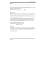
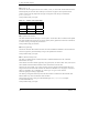
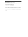
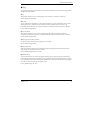
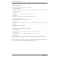
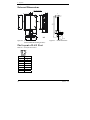
Part Names and Functions
LED:
Indicates the status of the power supply, wired LAN and wireless LAN.
Refer to Tables 2.1 - 2.3 for details.
DIP switch:
Used for initialization and for operation in IP-less mode.
See Table 2.4 for the setting method.
Antenna connectors:
Connect to the antennas. Connect supplied dipole antennas to these connectors.
Power supply connector:
Used to supply power to the product.
Also used to ground the product.
LAN port:
Connects to a hub or PC through 10-BASE-T/100-BASE-TX.
Also displays the wired LAN connection status using the LINK and ACT LEDs.
Figure 2.1. Part names
LED display
Table 2.1.
LED Displays during Normal Operation
LED name
Status
ON
POWER
Flashing
ON
WLAN
Flashing
OFF
LINK (LAN)
ACT (LAN)
Indicates that the device is operating.
Indicates that the device is being started (going to operate after the power
switch was turned on)
When the product is configured as an access point, the LED being ON indicates
that one or more stations are logged in the product.
When the product is configured as a station, the LED being ON indicates that the
product is logged in an access point.
Indicates data is being transmitted to or received from the device connected
through wireless LAN.
When the product is configured as an access point, the LED being OFF indicates
that no station is logged in the product.
When the product is configured as a station, the LED being OFF indicates that the
product is not logged in an access point.
ON
Indicates that a wired LAN has been connected.
OFF
Indicates that a wired LAN is not connected.
Indicates that the product is transmitting/receiving data to/from the connected
Flashing
terminal through wired LAN.
OFF
4
LED display
Indicates that the product is not transmitting/receiving data to/from the connected
terminal through wired LAN.
NZ2WL - xxx
2. Setup
Table 2.2.
During File Write
LED name
Status
POWER
Flashing
WLAN
simultaneously
*1
LED display
File write in progress *1
Except writing of log files (no flashing)
Table 2.3.
Error Display
LED name
Status
POWER
Flashing twice
WLAN
ON
LED display
Wireless LAN error
DIP switches
Table 2.4.
DIP Switches
ON
OFF
Operation / function
Turning on this switch flashes the POWER and WLAN LEDs.
If the switch is turned off before the LEDs change their status from flashing to
1
INIT
-
ON (about 3 seconds), all the settings are restored to the default settings after
the product is started next time. Reboot the product after the LEDs stop
flashing. *1
Turning on this switch allows the product to operate without the IP address
2
IP LESS
-
setting. The switch is used when an IP address is not allocated to the product
at the setup of a station. In this case, the TELNET, FTP, settings by Web
browser, and SNMP agent function cannot be used.
*1 The flashing continues for a little while after the product is switched off during initialization by switching
on and off the INIT switch. This indicates internal memory files are being deleted. The internal memory
files may be damaged and the product may not start up properly if the power is switched off before the
flashing stops. Always reboot the product after the flashing stops.
NZ2WL - xxx
5
2. Setup
Connectors
Table 2.5. Power Connectors
Name
Power connector
Function
Power terminal connector (included in the package): MC1,5/3-ST-3,5 (made by Phoenix
Contact Inc.)
The applicable cable is AWG28-16. (The cable length must meet the power supply
specifications.)
The applicable bar solderless terminals are AI0,25-6BU, AI0,34-6TQ and AI0,5-6WH
(made by Phoenix Contact Inc.)
Secure the connector with a retention bracket. Connect the power cable to the power
terminal connector by screw connection.
The fastening torque range is 0.22 to 0.25Nm.
Power connector
MC1,5/3-G-3,5 (Phoenix Contact)
12-24VDC
Vi+
ViFG
Pin number
Signal
Description
1
Vi+
Power (12-24VDC±5%)
2
Vi-
Power (GND)
3
FG
Frame Grand
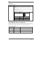
Checking the Network Addresses
The Ethernet (wired LAN), wireless LAN MAC address and IP address are defined on the housing
sticker on the side of this product. Write down the MAC addresses for Ethernet and wireless LAN in the
following table as they are device-individual values and may be required for future setup.
Table 2.6.
Network Address
Description on the
housing sticker
6
Explanation
IP:
Default IP Address
C:
Ethernet MAC Address
W:
Wireless MAC Address
Address
NZ2WL - xxx
2. Setup
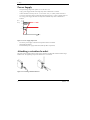
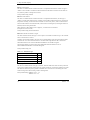
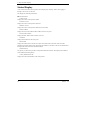
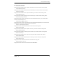
Attaching the Antennas
Use this product with the antennas included. The following describes how to attach the supplied dipole
antennas.
(1) Straighten both the antennas, as shown below, and attach them to the antenna connectors on the
main unit. The antennas screw onto the antenna connector. Adjust the position of the bending part
of the antennas taking into consideration how the antennas will be oriented. Next, place the
supplied rubber caps over the antennas and cover the antenna connectors.
(2) Bend the antennas to the desired angles. The antennas can also be used straight. Change the angle as
needed depending on the position of the unit.
<Example of vertical position>
(1)
(2)
<Example of horizontal position>
(1)
(2)
Figure 2.2. Attaching the Antennas
CAUTION
Using the product without connecting the antennas to the antenna connectors may cause the product
to malfunction. Be sure to use the product with the antennas connected.
FCC PART15, R&TTE Directive, NCC Certification addenda
(for USA, Europe, and Taiwan only)
The NZ2WL-US , NZ2WL-EU, and NZ2WL-TW comply with FCC PART15, the R&TTE Directive, and the
NCC Certification when used under the following conditions.
- Attach ferrite cores to the power supply line and the FG line.
The following picture shows the ferrite cores attached to the cable.
2cm from the EUT
6cm from the EUT
Attach ferrite cores to the FG line (2cm from the EUT) and the power supply line (6cm from the EUT), and turn
the cable three times (wind it twice).
NZ2WL - xxx
7
2. Setup
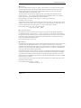
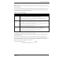
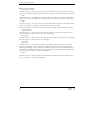
Power Supply
-
The input voltage range of this product is 12 to 24 VDC ±5%.
Using a power supply outside of that range may cause a malfunction or accident.
-
Connect the cables correctly to the Vi+ (12 to 24 VDC ±5%), Vi- (GND), and FG connectors.
-
Use a power source that starts up within the input voltage range of 11.4 VDC or higher within 24
ms. Using a power supply that does not satisfy these conditions may cause a malfunction or
accident.
Input
(V)
voltage 25.2
24
12
11.4
24
Time (ms)
Figure 2.3. Power Supply Input Time
-
The AC/DC power supply connected to the product must be CE-marked.
Ground the FG terminal.
Recommended power supply: PS5R-SF24 (made by IDEC Corporation)
Attaching a retention bracket
Plug in the power terminal connector to the power connector and attach the retention bracket using a
bracket screw. The tightening torque of the bracket screw is 0.588 Nm.
Figure 2.4. Attaching a Retention Bracket
8
NZ2WL - xxx
2. Setup
Grounding the NZ2WL
Connect the cables to the applicable connectors. Process the cables as needed and ground the product.
Figure 2.5. Grounding the NZ2WL
Installation
Using Mounting Brackets
Mounting on a Desktop (Horizontally)
When the product is used horizontally, it can be mounted on a desk or other surfaces using brackets.
Attach the product and brackets using the supplied bracket screws (tightening torque: 0.588 Nm), as
shown below, and place the side with the brackets down. Then secure the brackets on the desk using
tapping screws.
Figure 2.6. Mounting the Product on a Desk
Mounting on a Wall
The product can be mounted on a wall using mounting brackets. Attach the product and brackets using
the supplied bracket screws (tightening torque: 0.588 Nm), as shown below, and then secure the
brackets to the wall using tapping screws.
Figure 2.7. Mounting the Product on a Wall
NZ2WL - xxx
9
2. Setup
CAUTION
When mounting the product on a desk or wall,
place the product down with one of the
orientations shown to the right.
When mounting the product vertically, orient
the product with the LAN port on the bottom.
When mounting the product horizontally,
orient the product with the WLAN LED on the
bottom.
When mounting the product to a wall, secure
the rear of the product or the side of the
product closest to the WLAN LED to the wall.
Place the product as indicated above when
mounting it on the wall.
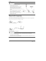
Wired LAN Connection
Connect the LAN cable to the LAN port on the product.
A cross cable is used to connect the product to the UP-LINK port of a PC or HUB. A straight cable is
used to connect the product to the normal port of a HUB.
Figure 2.8. Wired LAN Connection
CAUTION
-
The cable connecting the product to a hub, PC, or other device must not exceed 100 m.
-
Use a CAT-5 or CAT-6 STP cable.
-
This product cannot be used with IEEE 802.3af or other infrastructure that supplies power over an
Ethernet cable (Power Over Ethernet (PoE)).
10
NZ2WL - xxx
3. Connecting to Devices and Setup Methods
3. Connecting to Devices and Setup
Methods
This product is set up via a network using a Web browser or TELNET. Follow the setup procedure
below once the product is set up.
Setup Methods
Although the NZ2WL-xxx can be set up precisely to construct an advanced wireless LAN environment,
there are two different setup methods available: web browser and TELNET.
Web browser
-
Settings are easy with a graphical display and a help function.
TELNET
-
This terminal setting uses TELNET.
-
Only text is displayed, but settings are easy and quick.
Preparation before Setup
Since the product is set up via network, use a personal computer that can be connected to the network.
Connect the personal computer to the network and use a Web browser or TELNET for setting.
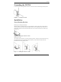
Connecting the product for the first time
(1) Connect this product to PC on a wired LAN.
(2) Select an IP address 10.XXX.XXX.XXX (e.g. 10.0.0.1) for the PC, which is not the same address
as for this product. And then set the subnet mask to 255.0.0.0.
Windows:
Click [Start] - [Control Panel] - [Network Connection], and then right-click the icon for local area
connection to open up the [Properties] screen. Select [Internet Protocol (TCP/IP)] from the
[General] tab and click [Properties]. Set up the IP address and subnet mask, and if necessary,
default gateway and DNS server on the opened [Internet protocol (TCP/IP) properties] window.
Changing the settings
(1) Connect this product to PC on a wired LAN.
(2) Set the network address of the PC to the same network address as for this product.
NZ2WL - xxx
11
3. Connecting to Devices and Setup Methods
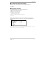
Setup Using Web Browser
This section describes the setup method using a Web browser. The following Web browsers can be used
(recommended Web browsers). Note that a proper display may not be shown on any browser other than
the following ones.
Enable the JavaScript function in the browser setting as it is used.
Supported web browsers (recommended)
-
Microsoft Internet Explorer 6 or later (7 or later recommended)
-
Mozilla Firefox 1.0 or later (3.0 or later recommended)
Setting the Browser
You may have to change the browser settings as well as the IP address and subnet mask for the PC to be
connected to this product via the network.
Changing browser settings
(1) Networks at companies and schools may use broswers with proxy settings. Proxy is not required as
a PC is used to set up the product, which is on a local network. Disable the proxy settings
temporarily when setting up this product on a Web browser.
For information about how to disable proxy settings, refer to the help section of the Web browser
used.
(2) Enable JavaScript.
For information about how to enable JavaScript, refer to the help section of the Web browser used.
CAUTION
If the Web browser settings have been changed, restore the browser settings to the original settings
after the setup of this product has been completed.
12
NZ2WL - xxx
3. Connecting to Devices and Setup Methods
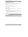
Connecting to This Product Using Web Browser
Start up a Web browser and enter the IP address of this product after “http : //” in the address bar.
If connecting to this product for the first time, enter the default IP address.When the default setting
IPaddress is 10.144.0.1, enter as follows.
http://10.144.0.1/
Connecting to this product displays the “Access Point Manager” login window, shown below.
If the login screen is not displayed, the IP address setting for PC, browser settings, or the URL entered
in the address bar of the browser may be incorrect.
Figure 3.1. Login Window (KR)
Enter a password on the login window and click “Login” to log in.
When connecting to the product for the first time, do not enter any password and just click “Login” as
no password has been set at the factory.
If the login is successful, the following setup window is displayed after a while.
Figure 3.2. Window after Login (KR)
-
-
Only the login window can be displayed before successful login. Before login, any attempts to
access pages other than the login window result in "Login Error." Log in first to access the pages.
Concurrent login is permitted for only one IP address. Attempting to log in while another user has
already logged in from another IP address causes "Multiplex access prohibition error." Wait until
the user logs out.
Reload the browser when the screen corrupts.
NZ2WL - xxx
13
3. Connecting to Devices and Setup Methods
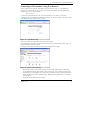
Setup Using Web Browser
Select “Setting” in the left-hand menu ((1) in Figure 3.3) and further select the desired setting items
from the opened menu. Information such as setting items will be displayed in the right-hand frame.
Figure 3.3. Setting by Access Point Manager (KR)
Click “Submit” ((2) in Figure 3.3) after changing settings on each page to temporarily save the settings
in this product.
The settings become enabled when the product is restarted after all the setup procedure is completed and
the settings are stored. Click “Save/Reboot” ((3) in Figure 3.3) on the left-hand menu.
The product can be rebooted later after the settings are saved, if necessary. In this case, saving the
settings does not actually change the settings of the product. Therefore, make sure to reboot the product
later.
"Time Out Error" will occur when there is no operation for approximately five minutes. The indicator (a
bar drawn with ".") on the status bar ((5) in Figure 3.3) represents the approximate time for timeout *1.
The number of "." is gradually decreased and all "." disappear before timeout.
*1
The indicator may not be displayed according to the version and/or the setting of the browser. For details on setting item, please
refer to “chapter 5 Setup and Status Display”.
For details on setting items, please refer to “Chapter 5 Setup and Status Display”.
CAUTION
It takes approximately 5 - 10 seconds to save settings (writing data to internal flash memory).
During that period, the POWER and WLAN LEDs at the front part of the main unit flash
simultaneously. Do not reboot or turn off the product until the screen indicates the completion of
the saving process.
The setup file data and firmware data may be damaged and the product may not operate properly if
it is rebooted or switched off during the saving process.
After the operation is completed, click "Logout". Closing the window without logout may prevent login
to other devices with other IP addresses and cause "Multiplex access prohibition error" on the devices.
To log in the device where "Multiplex access prohibition error" occurred, wait until the user who
currently logs in logs out or times out. Then try to log in again.
14
NZ2WL - xxx
3. Connecting to Devices and Setup Methods
Setup Using TELNET
This section describes how to perform setup using TELNET. This procedure requires an application in
which TELNET can be used. In Windows, “Command Prompt” can be used.
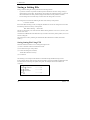
Connecting to the Product Using TELNET
Start up an application in which TELNET can be used (e.g. Command Prompt) and enter the IP address
of this product after the telnet command*1. When connecting to this product using TELNET for the first
time, enter the default IP address. For example, if the default IP address of the AP is [10.144.0.1], enter
as follows.
telnet 10.144.0.1
The following login window is displayed when connected to this product.
If the login window is not displayed, the IP address setting for the personal computer may be incorrect.
Figure 3.4. Login Window
Enter the password on the login window and press "Enter" to log in.
At the time of purchase, no password has been set up, so when connecting for the first time, just press
"Enter".
*1
The telnet command may not be initially available depending on the versions of Windows. For how to enable the telnet command,
refer to the Windows help screen.
NZ2WL - xxx
15
3. Connecting to Devices and Setup Methods
If the login is successful, the following window is displayed after a while.
Figure 3.5. Window after TELNET Login
CAUTION
”Shift JIS” is used as the character code displayed during TELNET connection. Check the character
code of the TELNET application if the characters become garbled.
16
NZ2WL - xxx
3. Connecting to Devices and Setup Methods
Setup Using TELNET
After login, enter the number of the item shown in the top menu depending on the desired execution,
and then press “Enter”. To perform configuration, enter “2” for “Configure”.
The items in the top menu are as follows.
Table 3.1.
TOP Menu
Menu
1. Exit
Description
Exit terminal setup.
2. Configure
Selected to configure settings.
3. Write Configuration
Used to save the settings.
4. Reboot
5. Update System Parameters
6. Download
7. Upload
Reboots the product. Reboot the product after changing the settings (after data write).
The new settings become enabled after the reboot.
Changes the password or date.
Downloads the setting file.
Sends the settings file from the connected personal computer (terminal) to the
product and updates the settings.
8. Default
Restores the settings to the factory default settings. The IP address can be excluded.
9. Status
Used to check the setting details and the status after startup.
Each item also has further subdivided sub-items. Enter the number of the desired sub-item.
After selecting a setting sub-item, a value is required to be entered. Enter an appropriate value.
A list of the values which should be entered can be displayed by entering “H” or “?” when entering a
value. When which value to enter is not clear, refer to “H or ?".
NZ2WL - xxx
17
3. Connecting to Devices and Setup Methods
TELNET Key Operation
Select items from the TELNET menus by entering the corresponding number. In addition to numbers,
the following commands can be also used. The keys can be used in all the menus. Capital and small
letters are not differentiated.
-
TT
Return to top menu
-
E
Escape from the current operation
-
M
Return to previous menu
-
GO
Jump to the specified category
-
JP
Change to Japanese mode (SHIFT-JIS)
-
US
Change to English mode
-
W
Save settings
-
BYE / OFF
End
-
H or ?
Display a list of commands (Help screen)
CAUTION
It takes approximately 5 - 10 seconds to save settings (writing to internal flash memory). During
that period, the POWER and WLAN LEDs at the front part of the main unit flash simultaneously.
Do not reboot or turn off the product until the screen indicates the completion of the saving process.
The setup file data and firmware data may be damaged and the product may not operate properly if
it is rebooted or switched off during the saving process.
18
NZ2WL - xxx
4. Wireless Link Mode and Wireless LAN Function
4. Wireless Link Mode and Wireless LAN
Function
This chapter describes the major functions of the NZ2WL series as a wireless LAN system and the
wireless link modes of the product along with configuration examples of networks available in the
wireless link modes.
Wireless Link Mode
This product has three wireless link modes. The available functions and network configurations differ
depending on the mode. Use the wireless link mode most suitable to the type of network you are
constructing. For details on the three modes, see "Features" in Chapter 1 and "Comparison of Main
Functions" in this chapter.
The factory default setting is “Advanced Infrastructure Mode”.
Chapters 3 and 5 describe the software setting procedures for the wireless link modes and related items.
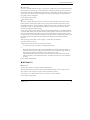
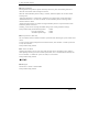
Standard Infrastructure Mode
In this mode, each access point (AP) can accommodate stations (ST) to make up a network.
This mode allows the use of multiple APs to configure a wide-area wireless LAN. All communication
between wireless terminals must go through an AP.
Figure 4.1.
Standard Infrastructure Mode
In the Standard Infrastructure mode above, all wireless terminals communicate via AP. Roaming
functions are supported, allowing login to any AP within range of radio waves.
For the IP tunneling function to work properly, one of the APs must be setup as a master AP.
* Normal AP: Normally operated device
Master AP: Device controlling access points in a network
Backup AP: Backup device that operates in case the master AP does not function for some reason
NZ2WL - xxx
19
4. Wireless Link Mode and Wireless LAN Function
-
Advantages
(1) If the IP tunneling function is used, communication can be performed over different routers
without changing IP addresses.
(2) Allows log-in restrictions (security function).
(3) Improves security using the WSL (Wireless Security Link).
Compatible Infrastructure Mode
This mode allows the product to be networked with other manufacturers’ Wi-Fi certified wireless
terminals other than the NZ2WL series. Communications between the wireless terminals are always
made via the APs.
CAUTION
The Compatible Infrastructure mode does not guarantee interconnection with Wi-Fi compliant
products of other manufacturers.
Figure 4.2.
Compatible Infrastructure Mode
In the Compatible Infrastructure mode, each wireless terminal performs communication via the AP as in
the Standard Infrastructure mode. Roaming functions are supported, allowing login to any AP within
range of radio waves.
APs do not provide NZ2WL series' unique functions since APs work as a simple bridge.
20
NZ2WL - xxx
4. Wireless Link Mode and Wireless LAN Function
Advanced Infrastructure Mode
The Advanced Infrastructure mode is a mixture of the Standard Infrastructure and Compatible
Infrastructure modes. The Advanced Infrastructure mode can be used only when the product is
configured as an access point.
Figure 4.3.
Advanced Infrastructure Mode
On the terminal set to the Standard Infrastructure mode, the NZ2WL series' unique functions can be
used.
The terminal set to the Compatible Infrastructure mode serves as a simple bridge and thus the NZ2WL
series’ unique functions cannot be used on this terminal.
NZ2WL - xxx
21
4. Wireless Link Mode and Wireless LAN Function
Comparison of Main Functions
The three wireless connection modes mentioned earlier have different wireless LAN functions. The
following table lists main functions of each mode and gives a brief explanation of each function.
"○" indicates that the function can be used and "×" indicates that the function cannot be used.
Table 4.1.
Comparison of Main Functions
Setting item
Standard
Compatible
Advanced
Infrastructure mode
Infrastructure mode
Infrastructure mode *1
Roaming
○
○
○
IP tunnel
○
×
○*2
SNMP
○
○
○
Log collection function
○
○
○
MAC address filtering
○*3
○*3
○*3
Bridge packet control
○*3
○*3
○*3
Data encryption (WSL)
○
×
○*2
Data encryption (WEP)
○
○
○
Super A/G
○
○
○
VLAN function
○*3
○*3
○*3
WDS function
○*3
○*3
○*3
○
○
○
XR
*1 The Advanced Infrastructure mode can be used only when the product is configured as an access point.
*2 The functions cannot be used between an access point in the Advanced Infrastructure mode and devices set to the
Compatible Infrastructure mode.
*3 MAC address filtering, bridge packet control, VLAN, and WDS are available only when the product is configured as
an access point.
Roaming
The roaming function allows stations to switch logins between multiple APs. The roaming function can
be used to construct a wide-area wireless LAN.
IP tunneling
With this function, the AP changes an IP address to allow a station to connect to a device in the desired
network group via access point in the different network group. This function is unique to the NZ2WL
series and cannot be used between an access point set to the Compatible Infrastructure mode and a
station set to the Compatible Infrastructure mode.
SNMP
This function enables remote management using software that supports SNMP. This function can be
used in all the modes.
Log collection function
This function collects event information such as a wireless communication of this product. For details,
refer to Chapter 6.
22
NZ2WL - xxx
4. Wireless Link Mode and Wireless LAN Function
MAC address filtering
This function can be used only when the product is configured as an access point. This function enables
only the terminals whose MAC address has been registered to be connected.
Bridge packet control
This function can be used only when the product is configured as an access point. An AP can pass only
data from network devices whose MAC address has been registered to the AP. Communication between
wireless terminals can be rejected when their MAC addresses are unregistered.
WSL (Proprietary encryption)
WSL (Wireless Security Link) is unique proprietary encryption built only in the NZ2WL series of
devices. It can be used either alone or along with other types of encryption such as WEP and AES.
Note, however, that devices using WSL cannot communicate with those not using it.
Data encryption
This function encrypts wireless data. For encryption, four security protocols are available: WEP (Wired
Equivalent Privacy), AES, AES-OCB and TKIP. AES and TKIP can be used with WPA, WPA-PSK,
WPA2, WPA2-PSK, WPA-AUTO, and WAP-AUTO-PSK.
Super A/G
Proposed by Atheros Communications, Inc., this technology speeds up communication. It improves
the throughput of wireless LAN using three techniques: "fast frames" for raising data transfer efficiency
by increasing the data packet size, "bursting" for decreasing inter-packet wait time, and "compression"
for compressing and decompressing data in real time.
VLAN function
This function can be used only when the product is configured as an access point. This function
organizes terminals on a network into virtual groups regardless of the physical configuration of the
network.
WDS function
This function can be used only when the product is configured as an access point. This function is a
wireless communication function between APs. An AP can wirelessly communicate with other APs
while communicating with a station.
XR
Promoted by Atheros Communications, Inc., this technology makes the communication distance longer,
compared with the existing communication distance, although the communication speed decreases. XR
can be used both in IEEE802.11a and IEEE802.11g specifications. For communication using XR, the
product must be connected to a device which supports the XR technology and has the XR function
enabled. If it is connected to any other device, XR will not be used and only the regular wireless
communication is available.
NZ2WL - xxx
23
4. Wireless Link Mode and Wireless LAN Function
Installation in a Network
This section describes how to install the product to construct a network with improved performance and
discusses the general features of the wireless network and characteristics of radio waves, as well as the
guidelines for constructing the network.
Features of the Wireless Network
In general, the operation of a wireless network is the same as for other similar types of LAN. The most
prominent feature of the wireless network is that it uses radio waves as its medium, eliminating the need
for cabling. The wireless network thus requires no cabling cost and has other advantages as listed
below:
-
Quick construction of a LAN
-
Temporary installation of a LAN
-
Higher flexibility in layout of connected PCs (terminals)
-
Assured mobility of connected PCs (terminals)
On the other hand, the wireless network has the following drawbacks from the operational point of view
due to the nature of radio waves :
-
Signal attenuation
-
Signal interference
Also, although this product does not require a radio license, it is subject to radio regulations of each
country.
24
NZ2WL - xxx
4. Wireless Link Mode and Wireless LAN Function
Operating Environment and Radio Waves
When using this product to construct a network, install and operate it considering the radio environment
to optimize the performance.
Is it allowed to use wireless devices at the installation location?
In some medical institutions and laboratories, radio-sensitive precision instruments are used and
it may be prohibited to use wireless devices.
Radio waves are attenuated.
Although a radio wave is attenuated naturally as it travels from its transmission source, it may also be
attenuated by an object existing in its way. Major obstacles that attenuate radio waves are as follows:
-
Concrete wall
-
Metal surfaces in the vicinity of the antenna
Obstacles blocking radio waves include metal walls and walls containing a metal firewall.
Strictly speaking, nearly all objects in the path of the radio waves (such as partitions and people) cause
some attenuation, but these do not have a significant impact on network performance.
RSSI (Receive Signal Strength Indication) utility is available as a means of knowing the signal strength
of an incoming radio wave. Placing this product for a greater RSSI value makes the communication
state more stable. If the RSSI value is small and does not increase by slightly moving the position of the
product, it means that the radio waves may be being attenuated by distance or obstacles.
Pay attention to radio interference.
Radio interference means that radio waves in the frequency band used by this network occurred outside
the network this product belongs to and that the reception of the radio waves is affected. Listed below
are major examples of sources of interfering radio waves generated in general environments other than
plants and factories:
-
5GHz (using IEEE802.11a) or 2.4GHz (using IEEE802.11b/IEEE802.11g) band wireless networks
that do not comply with IEEE802.11
-
Using IEEE802.11b/IEEE802.11g. (e.g. electronic devices that give off 2.4GHz band radio waves,
such as microwave ovens, security gates installed near entrances of some shops, and copiers)
When there is a large metal wall such as in a warehouse, the radio wave generated from the sender is
reflected, resulting in those radio waves reaching the receiver which have taken different routes (thereby
phase-shifted). This has the similar effect as the generation of interfering radio waves, possibly slowing
down data transfer.
Most of the interfering radio wave sources other than wireless networks have local and/or temporary
effects, not giving great effect to the network performance. Rarely, however, communication speed is
decreased and communication is disabled temporarily in the worst case. In such cases, changing the
location of this product may solve the problem.
NZ2WL - xxx
25
4. Wireless Link Mode and Wireless LAN Function
Constructing a Network
This section gives some pointers and cautions relating to constructing a network using the AP and
station and provides some practical examples.
(1) This product conforms with the standard wireless LAN specifications such as IEEE802.11a,
IEEE802.11g and IEEE802.11b. This enables setting to the same channel as that used in each
country and wireless communication between access points and stations responding to each channel.
Using different channels for wireless networks adjacent to each other
(In IEEE802.11a, set it to a channel such as 36 and 44 with 8ch or more apart, and in IEEE802.11g,
a channel such as 1, 6, and 11 with 5ch or more apart) prevents radio interference and improves the
throughput of the networks.
(2) Check the range of radio waves (hereinafter collectively called "cover area"). To use the AP with
two or more station logged in AP, all the stations must be installed within the cover area. The AP’s
coverage varies with obstacles (concrete walls, iron doors, elevator halls, etc.). Note also that the
number of transmission/reception errors increases if communication distance becomes longer to
some extent.
When setting up the network, check the RSSI level then confirm that communication works
correctly with the application you plan to use. For a TCP/IP system, for example, you can use the
Windows PING command. To use PING, start the command prompt (MS-DOS) and enter the
following command. The example command is for an AP with an IP address of 10.144.0.1, as
follows.
ping 10.144.0.1
(3) Two or more stations can log in the AP at the same time. However, remember that the
communication speed slows due to the increased loading as the number of stations increases for one
AP.
(4) If a pair of wireless terminals are communicating via a particular channel, no other devices can
communicate within the range of those radio waves (the exception is broadcasting which transmits
to all terminals). As a result, communication speed tends to drop as the density of wireless terminals
increases although this depends to a large extent on how frequently the network is used.
(5) If the AP is connected to an Ethernet hub or similar, an unexpectedly large load can occur on the
AP if the Ethernet traffic is heavy and this may reduce the performance of the wireless network.
This can be solved by changing the hub connected to the AP to a switching hub (bridge).
(6) Setup the software in accordance with how the network will be used.
(7) The communication speed may also drop due to interference if two wireless terminals are located
close to each other. In general, maintain a gap of about 1m between stations, 3m between APs and
stations, and 3m between APs.
(8) The best performance is achieved from antennas if they are located in an open space free from
obstructions. Avoid locating antennas where they will be hidden. In particular, when
communication distance is an important consideration, it is recommended that you install antennas
in a high location with a clear view.
(9) Floors often contain steel beams or metal firewalls and therefore communication on different floors
is often not possible.
26
NZ2WL - xxx
5. Setup and Status Display
5. Setup and Status Display
This chapter explains about setting items and status displays of this product. Always read Chapter 2
“Setup” and Chapter 3 “Connection to Devices and Setup Methods” for preparation before performing
setup or viewing the status. At the time of purchase, this product is configured as an access point.
This section describes how to setup this product and status displays using a web browser.
Settings
◆Basic setting
■Host
Name
Enter the host name of the product using 31 or less alphanumeric characters. Assigning a name to this
product allows easy identification on the network.
Factory default setting: (Not input)
■DHCP
Client
Enabling “DHCP client” makes this product available as a DHCP client.
Factory default setting: Disable
■IP
Address
Specify the IP address of the product. Make sure to perform this setting when not enabling the DHCP
client. When setting via a LAN using a browser running on a PC, the network address of the product
must be the same as the network address of the PC.
Factory default setting: (Specified on the housing sticker)
■Subnet
Mask
If using a subnet, specify the subnet mask.
If DHCP Client is set to "Enable", you can skip this setting.
Factory default setting: 255.0.0.0
■Default
Gateway
Specify the IP address of the router for the network to which the product belongs.
If DHCP Client is set to "Enable", you can skip this setting.
Factory default setting: 0.0.0.0
■AP
Composition
Sets the access point composition. Select "Compatible".
Normally, you do not have to change the default setting.
Factory default setting: Compatible
NZ2WL - xxx
27
5. Setup and Status Display
■Access
Point Type
The application type of the access point can be set by selecting “normal”, “master”, or “backup”. The
“master” device integrates access points on the network and the “backup” device substitutes for the
master AP if the master AP stops working for some reason.
As a basic rule, select "master". You can also select "master" when the product is configured as a station.
Normally, you do not have to change the default setting.
Factory default setting: Normal
■Master
AP IP Address
Specify the IP address of the wireless LAN device that serves as the master.
Factory default setting: 0.0.0.0
■Backup
AP IP Address
When the wireless LAN device for backup exists, specify its IP address.
Factory default setting: 0.0.0.0
■Language
Select either “Japanese” or “English” for the WEB setup screen and TELNET setup display language.
Factory default setting: English
■Password
Set a password. Enter a string of up to 31 alphanumeric characters. The password is case sensitive.
If you forget your password, initialize the product using the DIP switch (INIT).
The password is cleared when the product is initialized. Note, however, that initializing the product
resets all of its settings to their factory defaults, requiring you to make settings over again.
Factory default setting: (Not input)
28
NZ2WL - xxx
5. Setup and Status Display
◆Ethernet
■Port
Speed
Select the port speed setting. Select one of “Auto”, “100M Full Duplex”, “100M half Duplex”, “10M
Full Duplex”, or “10M half Duplex”.
Factory default setting: Auto
CAUTION
-
If one side is set to "Auto" and the other side is set to "100M Full Duplex", the communication
mode for the "Auto" side is recognized as "100M half Duplex". In this case, there may be a high
error rate and normal communication may not be possible. It is recommended that you set the
correct communication mode.
-
If one side or both sides are set to "Auto" and the two sides cannot recognize each other, set the
communication mode to the unchanging setting for both sides.
-
If port speeds are set incorrectly (for example, one side is set to unchanging 10M and the other side
is set to unchanging 100M), only one device may be able to establish a link or the link may be
repeatedly established and disconnected depending on the communication status. In this case, set
the correct communication mode.
■Link
Down Sense
Enabling the link down sense feature stops the wireless function when a link is regarded to be down in
the wired LAN at an access point.
The condition for detecting the link down-state is selected as a link-down condition: "Link status" or
"Ping". "Link status" sets the condition to "when a physical link is disconnected at the wired LAN port
of the product". "Ping" issues a ping packet periodically to a specified communication destination and
sets the condition to "when a reply error occurs".
Factory default setting: Wireless LAN … Disable
Link Down Condition … LinkStatus
■Ping
Parameter
These parameters are used when "Ping" is selected as the link-down condition.
Specify the IP address of the destination to which to periodically send a ping packet. Be sure to specify
a valid IP address of the other device connected to the wired LAN. Specify the transmission interval (in
seconds) of a ping packet issued. Enter a value between 1 and 65535.
Specify the response wait time (in seconds) for which to wait for a reply to a ping. Enter a value
between 1 and 15. Specify the retry count for when there is no response to a ping packet issued. Enter a
value between 0 and 15.
Factory default setting: IP Address … 0.0.0.0
Interval Time (s) … 60
Reply Waiting Time (s) … 3
Retry Count … 3
NZ2WL - xxx
29
5. Setup and Status Display
◆Wireless LAN
To change the wireless LAN standard, wireless connection mode, take three steps of “Basic” ->
“Details” -> “Security” to make their respective settings.
For any other item, you can change the setting on under “Details” or “Security”.
▼Basic
■Interface
Disabling “Interface” disables the internal wireless LAN module.
When switching from “Disable” to “Enable”, options such as channels do not appear in the “STEP 2
Details” setup as the built-in wireless LAN module function is suspended until this product is rebooted.
When you come to STEP 2, select “Save/Reboot” in the menu on the lefthand side of the Web browser
to save the settings and reboot the product.
Factory default setting: Enable
■Wireless
LAN Standard
Set the wireless LAN standard to be used.
When the unit type is "Access point", select one of the check boxes.
When the unit type is "Station", you can select more than one check box. In this case, the wireless LAN
standard is set automatically from among the set wireless LAN standards, according to the destination
access point. However, if the wireless LAN standard of the access point is not included among wireless
LAN standards set for the station, a connection to that access point cannot be established.
Factory default setting: IEEE802.11a and IEEE802.11g
■Wireless
Link Mode
Select the operation mode of the product from among “Standard Infrastructure”, “Compatible
Infrastructure”, and “Advanced Infrastructure (AP only)”.
Factory default setting: Advanced Infrastructure
Table 5.1.
Wireless Link Mode
Wireless link mode
Outline
Each access point can accommodate stations (such as wireless LAN cards) to make
Standard
up a network. This mode provides scalability from a middle- or large-scale system
Infrastructure
with multiple access points connected by LAN to a small-scale system based on a
single access point.
Compatible
This mode allows the product to be networked with other manufacturers' Wi-Fi
Infrastructure
certified wireless terminals other than the NZ2WL series.
Advanced
The access point can be used in both of the Standard Infrastructure and Compatible
Infrastructure (AP only)
Infrastructure modes. This mode is a mixture of the two.
30
NZ2WL - xxx
5. Setup and Status Display
■Unit
Type
Select either “Access point” or “Station”.
Factory default setting: Access point
Table 5.2.
Unit type
Unit type
Overview
Access point
Master access point controlling other stations or access points operating in station mode.
Station
Access points controlled by (logged into) another access point. For use when using as a bridge, for example.
■XR
function
To enable the XR (eXtended Range) function, set to “set to “Enable”.
When the XR function is enabled, the transmission rate is fixed to “Automatic”.
Factory default setting: Disable
▼Details
■ESSID
The name of the wireless LAN to which the AP belongs. Enter a name within 32 alphanumeric
characters. The name is case sensitive.
When the unit type is "Station", set ESSID same as the access point which wants to log in.
Factory default setting: LocalGroup
■Channel
This item is available when the unit type is “Access point”. Select the wireless channel to use. Select
from among the available channels for the country where used. The following are the available
channels.
Factory default setting: (depends on the country where used)
Table 5.3.
Country channels
Channel*1
Standard
U.S.A.
Europe
China
Korea
Taiwan
(NZ2WL-US)
(NZ2WL-EU)
(NZ2WL-CN)
(NZ2WL-KR)
(NZ2WL-TW)
36, 40, 44, 48,
IEEE802.11a
149, 153, 157, 161, 36, 40, 44, 48ch
165ch
IEEE802.11b/g
1-11ch
1-13ch
149, 153, 157, 161,
165ch
1-13ch
36, 40, 44,
149, 153, 157,
161ch
1-13ch
149, 153, 157, 161,
165ch
1-11ch
*1 The channels of this product can be changed only among the same models.
NZ2WL - xxx
31
5. Setup and Status Display
■Transmission
Rate *1
Sets the wireless transmission rate.
Select one from “Auto”, “54Mbps”, “48Mbps”, “36Mbps”, “24Mbps”, “18Mbps”, “12 Mbps”,
“9 Mbps”, “6 Mbps” for IEEE802.11a.
Select one from “Auto” , “11Mbps”, “5.5Mbps”, “2Mbps”, “1Mbps” when IEEE802.11b.
Select one from “Auto”, “54Mbps”, “48Mbps”, “36Mbps”, “24Mbps”, “18Mbps”, “12 Mbps”,
“9 Mbps”, “6 Mbps”, “11Mbps”, “5.5Mbps”, “2Mbps”, “1Mbps” for IEEE802.11g.
You can use "Max." to set the maximum transmission rate. Specify the maximum transmission rate
when the transmission rate is "Auto". For example, when the maximum transmission rate is "36Mbps",
an optimal transmission rate at or below 36 Mbps is used. You can use "Max." to set the maximum
transmission rate, but normally, you set "Transmission Rate" to the maximum value. You can set the
maximum transmission rate to any of the above transmission rates except "Auto".
*1 These are theoretical values based on their respective wireless LAN standards; they do not indicate
actual data transfer rates
Factory default setting: Auto, (Max.) 54Mbps
■Beacon
Transmission Rate
Sets the wireless transmission rate. Specify the beacon transmission rate. The options available to this
item are the same as those for the above transmission rate except “Auto”. Normally, this does not need
to be changed.
Factory default setting: 6Mbps
■Basic
Rate
This item is available when the wireless LAN standard is either "IEEE802.11g" or "IEEE802.11b" and
the unit type is "Access point". This sets the basic rate. Specify the basic rate which is the transmission
rate for control communication between access point and station. Normally, this does not need to be
changed from the default setting.
When the wireless LAN standard is "IEEE802.11g" and the 11g Only mode is "disabled," either
"IEEE 802.11" or "IEEE802.11b" can be selected. When the wireless LAN standard is "IEEE802.11g"
and the 11g Only mode is "enabled," either "IEEE802.11g" or "OFDM" can be selected.
When the wireless LAN standard is "IEEE802.11b," either "IEEE802.11" or "IEEE802.11b" can be
selected.
Factory default setting: No item
■TX
Power Level
You can decrease the transmission output to “50%” or “25%” by software setting. To decrease the
output, select either "50%" or "25%".
Factory default setting: MAX
32
NZ2WL - xxx
5. Setup and Status Display
■Super
A/G
This item sets the Super A/G feature for increasing the communication speed of wireless LAN. To use
Super A/G, enable the feature. Of the Super A/G feature, enable "Frame bursting" to use the frame
bursting function and enable "Real-time compression" to use the compression function.
To enable the Super A/G feature, usually, enable "Frame bursting". As real-time compression has no
effect on already compressed data (such as ZIP and jpeg files), enable or disable the function selectively
depending on the application of communication.
Factory default setting:
■802.11g
Function
Frame bursting
Real-time compression
… Disable
… Enable
… Enable
Parameter
This item is available when “IEEE802.11g” is selected as the wireless LAN standard.
IEEE802.11g can be set.
Parameter about
Enabling the “802.11g Only” mode rejects access from IEEE802.11b compliant station and accepts
access only from IEEE802.11g compliant station, resulting in communication with IEEE802.11g station
at higher data rates than when both types of station coexist with the "802.11g Only" mode disabled. This
item available when the unit type is “Access point”.
Enabling the protect mode enables stable communication even in an environment in which
IEEE802.11b-compliant products coexist with IEEE802.11g compliant station. Disabling the protect
mode makes communication a bit unstable but increases the communication speed to some extent.
For the protect type, specify the data packet configuration method. ”CTS-only” uses only CTS to
transmit and receive data. ”RTS-CTS” uses both RTS and CTS to transmit and receive data.
Communication speed of “CTS-only” is faster than that of “RTS-CTS”. This setting is enabled when the
protect mode is enabled. Normally, select "CTS-only".
Factory default setting:
■Antenna
802.11g Only mode … Disable
Protect mode … Enable
Protect type … CTS-only
Select
Specify the antenna to use. When set to "Auto", a diversity configuration with two external dipole
antennas is used. Select "1" when using only one antenna so as to disable the diversity configuration or
to connect using only one external antenna. Selecting "1" uses ANT1 and selecting "2" uses ANT2, but
when using only one antenna, it is recommended that "1" be selected for reasons related to the
characteristics of the product.
Factory default setting: Auto
NZ2WL - xxx
33
5. Setup and Status Display
■Multi
Client Function
This item is available when the wireless link mode is "Compatible Infrastructure" and the unit type is
"Station". Select "Enable" to enable the multi-client function that allows connection to more than one
PC, when the product is configured as a station.
Factory default setting: Disable
■Statistic
Node Address
This item is available when the wireless link mode is "Compatible Infrastructure", the unit type is
"Station", and the multi-client function is "Disable". Enter the MAC addresses of the PCs connected to
the product. Generally, set this item when connected to a receive-only device, such as a POS terminal.
Enter the MAC address "00-00-00-00-00-00", which consists of nothing but 0, meaning the function is
disabled, when not using the function.
When specifying a MAC address, enter a hyphen (-) at intervals of two characters.
(Example: 01-23-45-67-89-ab)
Factory default setting: 00-00-00-00-00-00
■Maximum
Number of Stations to Log In
This item available when the unit type is "Access point". The number of stations to log in AP is limited.
Enter a value between 1 and 254.
Normally, the maximum number is 254 units, but it varies depending on the encryption function of the
wireless LAN in use. The maximum number is 128 units when using IEEE 802.1X or AES-based
WPA/WPA2/WPA-AUTO or WPA-PSK/WPA2-PSK/WPA-AUTO-PSK encryption.
The maximum number is 32 units when using TKIP-based WPA/WPA2/WPA-AUTO or
WPA-PSK/WPA2-PSK/WPA-AUTO-PSK encryption.
Factory default setting: 254
Table 5.4.
Maximum Login
Encryption
Units
Encryptions other than those described below
254
IEEE802.1X
128
AES (when using WPA function)
128
TKIP (when using WPA function)
32
■Roaming
Threshold
This item is available when the unit type is “Station”. When the RSSI value of the currently connected
access point is smaller than the setting value, the product searches for a roaming-accessible access point
and roams into that access point if possible. Threshold can be set from 0 to 95. Increasing this value
makes roaming easier and decreasing it makes roaming harder.
Factory default setting: IEEE802.11a/g … 24
IEEE802.11b … 24
34
NZ2WL - xxx
5. Setup and Status Display
■Priority
AP
This item available when the unit type is “Station”. This item allows you to specify the access point to
be connected preferentially. Enter the wireless MAC addresses of the access points in AP1 to AP5.
Wireless MAC addresses of access points can be checked on “Status” for each access point and
“Wireless MAC address” of the “Wireless LAN”.
The access points to be connected are assigned priorities in ascending order beginning with AP1
(followed by AP2, …, AP5). Entering wireless MAC addresses enables this function. To disable this
function, enter zeroes (00-00-00-00-00-00) for all MAC addresses.
When specifying a MAC address, enter a hyphen (-) at intervals of two characters.
(Example: 01-23-45-67-89-ab)
If the product is unable to connect to any of the access points AP1 to AP5, set "Connect to other APs" to
"Enable" to allow a connection to other access points. To prevent the product from connecting to access
points other than the prioritized access points, set "Connect to other APs" to "Disable".
Factory default setting: AP1 - AP5 … 00-00-00-00-00-00
Connect to other APs … Enable
■Communication
distance
Extending the ACK time-out interval prevents ACK time-out from occurring during long-distance
communication. Select "Less than 1 km", "1 - 10 km", "10-20 km", or "Over 20 km". This item adjusts
the ACK time-out interval and each option is a guide setting of the time-out interval. It does not increase
transmission output or antenna gain to expand the communication distance. Normally, this does not
need to be changed from the default setting.
Factory default setting: Less than 1 km
■Load
Balance
Load balancing is the function used to prevent wireless terminals from flocking to one access point upon
connection. When the load balance function is set to “Enable” and the unit type is "Access point",
notification of the number of stations logged in is sent and the stations are connected to the access point
with fewer connections preferentially. When the unit type is "Station", a connection is established to the
access point with fewer connections preferentially.
Set the RSSI threshold of the connected access points to the load balance threshold. When the product is
roaming or connecting to an access point, a connection is established to the access point with an RSSI
value higher than the setting value and with the fewest possible logged in connections. Enter a value
between 0 and 95. The load balance threshold must exceed the roaming threshold. This item is available
when the unit type is "Station".
To use this function, the access points and stations must be NZ2WL Series products and must have the
load balance function enabled.
Factory default setting: Function … Disable
Load balance threshold … 30
NZ2WL - xxx
35
5. Setup and Status Display
■Beacon
Interval
This item is available when the unit type is “Access point”. Specify the transmission interval at which
the access point transmits a beacon signal. Enter a value between 20 and 1000 in milliseconds (ms).
Normally, this does not need to be changed.
Factory default setting: 100 (ms)
■DTIM
This item is available when the unit type is “Access point”. Set the interval at which to add a DTIM
(Delivery Traffic Indication Message) to a beacon signal, which is information for recovering a station
from power-save mode. Enter a value between 1 and 255.
Setting this item to 1 adds a DTIM to each beacon signal and setting it to 2 adds one to every other
beacon signal.
Factory default setting: 1 (time)
■QoS
This function preferentially sends a specific packet, such as VoIP.
This can be used, for example, to provide the optimal environment for an internal IP phone system using
wireless LAN.
To enable the QoS function, set it to "Enable".
Factory default setting: Disable
■WDS
This item is available when the unit type is “Access point”. To enable the WDS function, set it to
"Enable". In that case, you must specify the wireless MAC addresses of the remote APs with which to
communicate. Use the "Edit List" button to open another window for setup and set the MAC address.
You can register up to six wireless MAC addresses for inter-AP communication.
When specifying a MAC address, enter a hyphen (-) at intervals of two characters.
(Example: 01-23-45-67-89-ab)
The types of encryption available for wireless LAN setup are WEP, AES, and AES-OCB. WPA cannot
be used. In addition, the IEEE 802.1X function cannot be used in conjunction.
The WDS function cannot be used when channel 56, 60 or 64 has been selected for IEEE 802.11a. Use a
different channel.
Factory default setting: Disable
■Power-save
Mode
This item is available when the unit type is "Station". To enable power-save mode, set it to "Enable".
Enabling power-save mode can reduce power consumption of wireless devices. This is effective when
operating on battery power, but it reduces performance, so it is recommended that normally this be set
to "Disable".
Factory default setting: Disable
36
NZ2WL - xxx
5. Setup and Status Display
▼Security
■Encryption
This setting specifies whether to enable or disable encryption. You can select a type of encryption from
among "WEP", "AES", "AES-OCB", and "TKIP". If you select "AES" or "TKIP", one of the WPA
functions described later can be used. When "TKIP" is selected, use one of the WPA functions. If you
disable encryption, neither key can be used as the default key.
Factory default setting: Disable
Table 5.5.
Encryption
Wireless Link Mode
WPA
WEP
x
AES
O
AES-OCB
x
TKIP
O
■WPA
Setup
Function
WPA cannot be used.
Set one of the keys #1 to #4 for use.
Select whether or not to use WPA.
You do not have to set key #1 to #4 when WPA is used.
WPA cannot be used.
Set one of the keys #1 to #4 for use.
WPA must be used.
You do not have to set key #1 to #4.
function
Specify the authentication type when WPA is used.
been set to "AES" or "TKIP".
This item can be set only when encryption has
The available authentication types are "WPA", "WPA-PSK", "WPA2", "WPA2-PSK", "WPA-AUTO",
and "WPA-AUTO-PSK".
"WPA-AUTO" and "WPA-AUTO-PSK" are modes combining WPA (-PSK) and WPA2 (-PSK). When
these modes are used, it is determined whether each station uses WPA (-PSK) or WPA2 (-PSK) and
communication is performed according to the authentication type of each station.
To use IEEE 802.1X authentication-based WPA, select "WPA", "WPA2" or "WPA-AUTO" and set up
IEEE 802.1X.
To use WPA without an authentication server, select "WPA-PSK", "WPA2-PSK", or
"WPA-AUTO-PSK", and set the WPA encryption key described below.
When encryption is "AES", you can select "Disable". WPA is not used at this time. When encryption is
"TKIP", you cannot select "Disable". Select an item other than "Disable".
"WPA-AUTO" and "WPA-AUTO-PSK" are available only when the unit type is "Access point". These
items cannot be set when the unit type is "Station".
Factory default setting: Disable
■Default
Key
Set this item when encryption has been set to "WEP", "AES", or "AES-OCB" and the WPA function is
disabled. Select the key number to be used, from among keys #1 to #4.
Factory default setting: #1
NZ2WL - xxx
37
5. Setup and Status Display
■Size
/ Key #1 - #4
Set this item when encryption has been set to "WEP", "AES", or "AES-OCB" and the WPA function is
disabled. Specify the size and value of the key to be used for encryption. The acceptable size and
number of digits of the key depend on each type of encryption. Enter the key in hexadecimal
(0 - 9, a - f, or A - F).
Factory default setting: (No input)
Table 5.6.
Encryption
Number of Key Input Digits
Size and No. of Input Digits
64bit
10
WEP
128bit
26
152bit
32
AES
128bit
32
AES-OCB
128bit
32
■Key
Update Time (minutes)
This item available when the unit type is “Access point”. Set this when WPA is enabled. Set the update
time of the broadcast key (group key) in minutes. Specify the key update interval between 0 and 65535
in minutes. Setting it to 0 stops key transmission.
Factory default setting: 60 (minutes)
■WPA
Encryption Key
Set this item when the WPA function has been set to WPA-PSK/WPA2-PSK/WPA-AUTO-PSK. Enter
a WPA encryption key (Pre-Shared Key) using 8 to 63 alphanumeric characters.
Factory default setting: (No input)
■WSL
(Wireless Security Link)
This item is available when the wireless link mode is "Standard Infrastructure" and "Advanced
Infrastructure (AP only)".
Select whether to enable or disable proprietary encryption (WSL) for wireless data. Note, however, that
WSL-enabled and WSL-disabled terminals cannot communicate with each other.
There are two types of WSL: Type 1 using an earlier version of the encryption algorithm and Type 2
using the latest version. When the wireless LAN standard is "IEEE802.11a", only Type 2 can be used.
When it is "IEEE802.11b" or "IEEE802.11g", either Type 1 or Type 2 can be selected.
Select the right type according to application.
The WSL key setting takes effect only when the WSL function is enabled. Note that terminals with
different WSL keys cannot communicate with each other.
Enter the WSL key using a string of 20 hexadecimal digits (0 - 9, a - f, or A - F). (Example:
0123456789abcdef0123)
Factory default setting: (No input)
38
NZ2WL - xxx
5. Setup and Status Display
■ESSID
security
This item is available when the unit type is “Access point”. ESSID security is the composite function as
the combination of “ANY ID reject” and “ESSID hide”. Enabling this function rejects access by ANY
ID terminals (those with no ESSID assigned) and hides the AP’s ESSID from external references to the
access point. Using the function restricts illegal access using ANY ID and prevents the ESSID from
being easily known to third parties.
Factory default setting: Disable
■MAC
address filtering
This item is available when the unit type is “Access point”. Select whether to use the MAC address
filtering function. Enabling the function rejects access by stations other than those stations with an
authorized MAC address. All network devices connected to the stations over Ethernet are permitted /
prohibited as a whole. To edit authorized MAC addresses, click the "Edit List" button to open the
window for setting MAC address filtering.
On the setting window of MAC address filtering, authorized MAC addresses can be added and deleted.
To add one MAC address, enter the MAC address in "Starting address" and click the "Add" button. To
add a series of consecutive MAC addresses, enter the first MAC address in "Starting address" and the
last MAC address in "Ending address", and then click the "Add" button. To delete a MAC address, click
the "Delete" button to the right of the MAC address to be deleted in the list of authorized MAC
addresses.
When specifying a MAC address, enter a hyphen (-) at intervals of two characters.
(Example: 01-23-45-67-89-ab)
Add the wireless MAC address of the station to the list when;
-
the wireless link mode of the station is "Standard Infrastructure."
or
-
the wireless link mode of the station is "Compatible Infrastructure" and "Multi client function" is
enabled on the station. Wireless MAC address of Station can be confirmed by using “Status” of
each Station and “Wireless MAC address” of the “Wireless LAN” items.
Add the MAC address of the network device connected with the station when the wireless link
mode of the station is "Compatible Infrastructure" and "Multi client function" is NOT enabled on
the station.
Factory default setting: Disable
◆IEEE802.1X
■IEEE802.1X
Set this item to “Enable” to enable the function of IEEE802.1X.
When the IEEE 802.1X function is "Enable" and WPA/WPA2/WPA-AUTO is not used, be sure to
select "WEP" for the wireless LAN security setting to enable key exchange.
This function is not available when the unit type is "Station", so select "Disable".
Factory default setting: Disable
NZ2WL - xxx
39
5. Setup and Status Display
■MAC
Address Authentication Function
To enable the MAC address authentication function, set it to "Enable".
Factory default setting: Disable
■Reauthentication
Interval (minutes)
Specify the interval at which to perform reauthentication. Specify a value between 2 and 4320
(minutes).
Factory default setting: 60 (minutes)
■WPA
Reauthentication
Specify whether to periodically perform RADIUS server reauthentication when "WPA", "WPA2", or
"WPA-AUTO" is selected for "WPA Function".
When this is "Enable", reauthentication is performed at the time set in "WPA Reauthentication Interval
(minutes)".
Factory default setting: Disable
■WPA
Reauthentication Interval (minutes)
When "WPA Reauthentication" is enabled, set the interval in minutes at which to perform RADIUS
server reauthentication. Specify a value between 2 and 4320 (minutes).
Factory default setting: 1440 (minutes)
■(RADIUS
server) IP address
Enter the IP address of the RADIUS server.
Factory default setting: 0.0.0.0
■(RADIUS
server) Port number
Enter the port number used for communication with the RADIUS server.
Factory default setting: 1812
■(RADIUS
server) ESSID
When switching to the RADIUS server specified in "IP address" above, the ESSID of the access point
changes to the ESSID set here. Set this item only when using this function. Leave this item blank when
you do not need to use this function.
Factory default setting: (No input)
■(RADIUS
server) Pre-shared Key
Enter the pre-shared key of the RADIUS server.
Factory default setting: (No input)
40
NZ2WL - xxx
5. Setup and Status Display
◆Extension
■Bridge Packet Control
This item is available when the unit type is “Access point”. Enabling bridge packet control prevents file
sharing among clients under the same access point. To create a network that permits file sharing, use
"Edit List" to open a separate window and then register the MAC address of the router or device for
which file sharing is permitted.
When specifying a MAC address, enter a hyphen (-) at intervals of two characters.
(Example: 01-23-45-67-89-ab)
Register the wireless MAC address of the station when the wireless link mode of the station is
"Compatible Infrastructure" and "Multi client function" is enabled on the station. When multiple devices
are connected to the station, shared files are permitted / prohibited as a whole. Wireless MAC address of
Station can be confirmed by using “Status” of each Station and “Wireless MAC address” of the
“Wireless LAN” items.
Otherwise, register the MAC address(es) of the network device(s) connected to the station. Shared files
are permitted / prohibited for each device.
Factory default setting: Disable
■Network
Time
Enabling the network time function can synchronize the access point time with the network time.
To enable this function, set the IP address and time zone of a network time server on the network.
(Example: For use in Japan, enter “+09 : 00” (meaning UTC + 9 hours) as the Japan standard time is
nine hours ahead of Universal Time Coordinated (UTC).)
Factory default setting: Function …Disable
IP Address … 0.0.0.0
Time Zone … +09 : 00
■Access
Control
Set the access control for this product. Disabling TELNET, FTP, WEB server function rejects the
connection to each server. Note that if disabling all the settings, the product cannot be accessed for
setup.
Enabling specification of administrator IP, you can specify the IP address to connect to TELNET, FTP,
WEB. Up to two administrator IP addresses can be registered in “Administrator IP address 1” and
“Administrator IP address 2”.
When using this function, you need to enable server functions such as TELNET. Note that if only
disabled IP addresses are registered, the connection to the product using the TELNET, FTP, and WEB
cannot be made.
When the "Wireless Access" is set to "Disable", the connection from a wirelessly connected station to
the product using the TELNET, FTP and WEB is rejected. When the setting is "Enable", connections
from a wirelessly connected station are permitted.
Factory default setting: TELNET / FTP / WEB Server … Enable
Administrator IP Address … Disable
Administrator IP Address 1 - 2 … 0.0.0.0
Wireless Access … Enable
NZ2WL - xxx
41
5. Setup and Status Display
■Network
Delay Time (s)
Specify the maximum delay time acceptable to the network.
When an access point communicates with the server or another access point, a communication time-out
may occur if an intermediary line is slow in communication speed. If this is the case, increase the
network delay time to prevent a time-out from occurring.
Enter a value between 0 and 15.
Normally, you do not have to change the default setting.
Factory default setting: 0 (seconds)
■Encryption
Config File
When this is “Enable”, the setup files (CONFIG) are encrypted and saved to the internal memory when
the settings are saved.
Whether setup file encryption is “Disable” or “Enable”, both encrypted and unencrypted setup files can
be used when those files are written to this product by file transfer.
The password set in this product (up to 31 alphanumeric characters) is used as the password for the
encryption.
Factory default setting: Disable
42
NZ2WL - xxx
5. Setup and Status Display
■Protocol
Filter
When this is "Enable" and a filter is registered, specific protocol (such as TCP and UDP) packets can be
blocked or allowed.
To edit a filter, click the "Edit List" button to open the window for setting the protocol filter list, and
then edit the filter. Set the following settings in the window for setting the protocol filter list, and then
click the "Add" button to register the filter to the list.
Table 5.7.
Protocol filter setting
Setting Item
Operation
Setting Method
Select whether to allow or block specified packets.
Specify the Ethernet frame type to "IP (0x0800)", "ARP (0x0806)", "RARP (0x8035)" or “802.3 (0x0 to
0x05DC)”, or specify a user-defined type other than an IEEE 802.3 Length Field.
Ethernet type
When specifying a user-defined value, enter a value between 0x05dd and 0xffff (1501 to 65535). When
registering a hexadecimal value, start with "0x". When registering a decimal value, enter the value as is.
You can define only one individual value and one range.
Enter this when "IP" is selected as the Ethernet type.
You can specify the protocol number included in the IP header. You can specify "All (0 - 255)", "TCP (6)", "UDP
IP protocol
(17)" or "ICMP (1)" or specify a user-defined protocol number.
When specifying a user-defined value, enter a value between 0 and 255 (0x0 to 0xff). When registering a decimal
value, enter the value as is. When registering a hexadecimal value, start with "0x".
You can define only one individual value and one range.
Enter this when "TCP" or "UDP" is selected as the IP protocol.
You can specify the TCP or UDP port number. Specify "All (0 - 65535)" or "User defined".
Port number
When specifying a user-defined value, enter a value between 0 and 65535 (0x0 to 0xffff). When registering a
decimal value, enter the value as is. When registering a hexadecimal value, start with "0x".
You can define only one individual value and one range.
The registered filter is displayed in the table below the input form.
To delete a registered filter, click the "Delete" button for that filter. Clicking the "All" button on the
table deletes all filters.
Specify "Allow" or "Block" for the action of protocols whose action has not been specified in the
protocol filter list. When specifying "Block", be sure to register those protocols that are required for use
of this product to the filter as "Allow". Note that communication to this product is allowed even if
"Block" is specified, so the setting can be changed later.
Factory default setting: Function
… Disable
Operation of unspecified protocols … Allow
NZ2WL - xxx
43
5. Setup and Status Display
■Roaming
Notification
Roaming notification packets are packets that notify other access points and switching hubs that a
station has moved when station roaming has occurred.
When the "Send notification packets" setting is "Enable", notification packets are sent when station
roaming occurs.
"First login notification" is a setting that is enabled for access points whose wireless link mode is
"Standard Infrastructure". Use this to set whether to send notification packets at first login after a
connected station is started.
"Notification packet bridge" sets whether to bridge notification packets to a separate interface when
notification packets are received.
Normally, you do not have to change the default settings of the roaming notification settings.
Factory default setting: Send notification packets
First login notification
Notification packet bridge
■Delete
… Enable
… Enable
… Enable
System Files (INIT-SW)
This sets whether to delete certificates and other system files when initializing the system with the INIT
switch.
To restore only the settings and password to the default values, select "Disable". To delete system files
as well, select "Enable".
Factory default setting: Disable
■CPU
Power-save Mode
Operating this product's CPU in power-save mode can reduce power consumption. This is effective
when operating on battery power, but it reduces performance, so it is recommended that normally this
be set to "Disable". To enable CPU power-save mode, set it to "Enable".
Factory default setting: Disable
◆SNMP
■SNMP
Agent
Set this item to “enable” to enable SNMP.
Factory default setting: Disable
44
NZ2WL - xxx
5. Setup and Status Display
■Community
Name
Enter the SNMP authentication string. The SNMP authentication string serves as a password to access
this product using SNMP. Programs use this community name to access MIB of this product. *1
Enter a string of up to 32 alphanumeric characters. The community name is case sensitive.
Factory default setting: public
*1 Management Information Base: complies with RFC1213 and RFC1493
■Access
Right
Set the access right for the community. Select “Read/Write” or “Read Only”.
Factory default setting: Read / Write
■Trap
IP Address
Trap is the function to notify a user of a change made within the SNMP agent system. The trap function
can be enabled by specifying the IP address of the destination user. The SNMP manager having the IP
address specified here can manage trap information of this product.
If the network contains more than one AP, it is advisable to register the same IP address so that all the
APs can be managed on one machine. If the network contains more than one wireless terminal, it is
advisable to register the same IP address so that all the wireless terminals can be managed on one
machine. Up to three destinations IPs can be registered.
Factory default setting: 0.0.0.0
■sysContact
Enter contact information of the administrator of this product. An example is the name and telephone
number of the network administrator. The string can be up to 32 alphanumeric characters.
Factory default setting: (No input)
■sysLocation
Specify the physical location of this product. An example is “Administration Division, 2F”. The string
can be up to 32 alphanumeric characters.
Factory default setting: (No input)
■sysName
Specify the device name of this product under SNMP. Enter a string of up to 32 alphanumeric characters.
The sysName is case sensitive.
Factory default setting: (No input)
■Trap
When the trap function is enabled, a trap is transmitted when the Ethernet or wireless LAN link status
changes (goes down). This can be set separately between Ethernet and wireless LAN.
Factory default setting: Ethernet … Disable
Wireless LAN … Disable
NZ2WL - xxx
45
5. Setup and Status Display
◆VLAN
■VLAN
This item is available when the unit type is “Access point”. Set this item to "Enable" to enable the
VLAN function.
Factory default setting: Disable.
■VLAN
ID
This item is available when the unit type is “Access point”. Specify the VLAN ID of this product
between 1 and 4096.
Factory default setting: 1
■Guest
Access
This item is available when the unit type is “Access point”. Select whether to permit the guests in the
guest VLAN ID group other than the VLAN ID groups registered in the VLAN table to access the
station. To enable guest access, set this item to "Enable".
Factory default setting: Enable.
■Guest
VLAN ID
This item is available when the unit type is “Access point”. Set this item if you set guest access to
"Enable." Set the VLAN ID for each guest to a value between 1 and 4094. Guest VLAN IDs must be
different from any VLAN ID in any other VLAN group registered in the VLAN table.
Factory default setting: 1
■RADIUS
server
This item is available when the unit type is "Access point" and the IEEE 802.1X function or MAC
address authentication function is "Enable". Specify the RADIUS server for use with guest VLAN. The
displayed number refers to the number of the RADIUS server with IEEE802.1X selected. Select the
RADIUS server number for connections to be allowed.
Factory default setting: (All selected)
■VLAN
table
This item is available when the unit type is “Access point”. Set a VLAN group. You can set up to 16
VLAN groups. Use "Edit List" to open the VLAN group setup window to set VLAN groups. Enter the
ESSID and VLAN ID for each VLAN group. The ESSID and VLAN ID must be different from those of
any other VLAN group or any guest VLAN group.
If WEP (without use of IEEE 802.1X), AES-OCB, or AES not used for WPA is selected for encryption
during wireless LAN setup, the encryption setting for each VLAN group can be changed. In this case,
the encryption setting is displayed, allowing you to set the encryption key for each VLAN group. You
can also change the key size when using WEP.
The RADIUS server to be used by each VLAN group can be specified when the IEEE 802.1X or MAC
address authentication function is enabled. The displayed number refers to the number of the RADIUS
server with IEEE802.1X selected. Select the RADIUS server number for connections to be allowed.
This allows you to specify a different RADIUS server for each VLAN group.
Factory default setting: (Not setup)
46
NZ2WL - xxx
5. Setup and Status Display
◆Log
The product can preserve log information. See Chapter 6 “Maintenance” for details of the logged data
and data collection methods.
■Log
This specifies whether or not to enable logging. Set the function to "Enable" to collect logs.
Factory default setting: Disable
■File
Save
To save collected log information as a file, enable the function. To store it temporarily in the memory,
disable the function. “Temporarily” here means the period in which the device is running. Log
information will be deleted if this product is rebooted or switched off when the function is “Disable”.
Factory default setting: Disable
■Overwrite
Mode
This specifies whether or not to overwrite old data when the number of log entries reaches the
maximum. If disabled, log collection is suspended when the maximum number of entries is reached.
Factory default setting: Enable
■Starting
Day/Time Setting Function
To specify the date and time to start logging, set it to "Enable".
Factory default setting: Disable
■Starting
Day/Time
When the starting day/time function is enabled, specify when logging should be started. Enter four
digits for the year. (Example: 2010 Jan. 1 00:00)
Factory default setting: 2002 Jan. 1 00:00
■Detailed
Setting
You can select the types of events to be logged. Setting [Login], [Logout], [Login NG], [Roaming],
[Tunnel Start], [Tunnel Stop], [Application Login], [Application Logout] and [Auth Success / Error] to
“ON” allows the selected events to be logged. Setting them to “OFF” prevents them from being logged.
See Table 5.8 for a description of the types of events.
Factory default setting: All "ON"
NZ2WL - xxx
47
5. Setup and Status Display
Status Display
A list of status information on this product can be displayed by selecting “Status” after logging in
through a web browser or TELNET.
This displays the following information.
■Basic
-
Informastion
Loader Version
Displays the version of this product's loader.
-
Firmware Version
Displays the version of this product's firmware.
-
Hardware Version
Displays the version of this product's hardware (circuit board).
-
Ethernet Address
Displays the wired LAN (Ethernet) MAC address of the access point.
-
Wireless MAC Address
Displays the MAC address of the wireless LAN card.
-
IP Address
Displays the IP address of the access point.
-
Subnet Mask
Displays the subnet mask set for the access point. The subnet mask is the mask value used when
obtaining the network address of the subnet from the IP address. The subnet value can be obtained from
the logical OR of the mask value and the IP address.
-
Default Gateway
The gateway is a device that provides a relay between different networks. This displays the IP address
of the standard connected gateway.
-
Country Identification Code
Displays the country identification code of this product.
48
NZ2WL - xxx
5. Setup and Status Display
■Interfaces
-
MTU
The maximum transmission unit (MTU) is the maximum length of data that can be transmitted in one
transmission. This displays the MTU for each interface.
-
Transfer Speed
Displays the data transfer speed for each interface.
-
MAC Address
Displays the MAC address for each interface.
-
Interface / Link Status
Displays whether each interface is active and connected to the network.
-
RX Octets
Displays the number of data bytes received by the access point.
-
RX Unicast Packets
Unicast is the transmission of data to a specific destination in the network by specifying a single address.
This displays the number of unicast packets received by the access point.
-
RX Broadcast Packets
Broadcast is the transmission of data to multiple unspecified destinations in the network. This displays
the number of broadcast packets received by the access point.
-
RX Discards
When data is damaged for some reason, those data packets are discarded. This displays the number of
times data that have been discarded.
-
RX Errors
Displays the number of errors that occurred when receiving data.
-
RX Errors (CRC)
CRC (Cyclic Redundancy Check): Displays the number of errors detected during a CRC.
-
TX Octets
Displays the number of data bytes transmitted by the access point.
-
TX Unicast Packets
Displays the number of unicast packets transmitted by the access point.
-
TX Broadcast Packets
Displays the number of broadcast packets transmitted by the access point.
-
TX Wait Count
Displays the number of times waiting that occurred for data transmission when transmitting data.
-
TX errors
Displays the number of errors that occurred when transmitting data.
-
Reset Count
Displays the number of resets that occurred in an interface.
NZ2WL - xxx
49
5. Setup and Status Display
■Wireless
-
LAN information
Wireless LAN Standard
Displays the currently operating wireless LAN standard.
-
Wireless Link Mode
Displays the currently operating wireless LAN mode: Standard Infrastructure, Compatible Infrastructure,
or Advanced Infrastructure.
-
Unit Type
Displays the current wireless LAN type: Access point or Station.
-
Module ID
Displays the ID of the wireless device incorporated in this product.
-
Wireless MAC address
Displays the MAC address of the wireless LAN card.
-
Login AP
When the unit type is "Station", this displays the wireless MAC addresses of the access points logged in
to this product.
-
ESSID
Displays the ESSID set for this product.
-
Channel
Displays the wireless LAN channel used by this product.
-
Transmission Rate
Displays the transmission rate (in Mbps) at which data is currently being transmitted.
-
Receive Rate
Displays the transmission rate (in Mbps) at which data is currently being received.
-
Number of login
When the unit type is "Access point", this displays the number of stations logged in to this product.
-
RSSI
When the unit type is "Access point", this displays the received signal strength indication (RSSI) of the
unit, which is a measurement of the strength of the signal being received.
50
NZ2WL - xxx
5. Setup and Status Display
■Wireless
-
Statics Information
Transmit Unicast Packets
Displays the total number of unicast packets transmitted by the wireless interface of this product.
-
Transmit Multicast Packets
Displays the total number of multicast packets transmitted by the wireless interface of this product.
-
Transmit Unicast Bytes
Displays the total number of unicast bytes transmitted by the wireless interface of this product.
-
Transmit Multicast Bytes
Displays the total number of multicast bytes transmitted by the wireless interface of this product.
-
Transmit Retry (Single) Packets
Displays the number of times that packets have been retransmitted one time, due to reasons such as
wireless LAN transmission error.
-
Transmit Retry (Multiple) Packets
Displays the number of times that packets have been retransmitted multiple times, due to reasons such
as transmission error from the wireless interface of this product.
-
Number of Transmit FIFO Underruns
Displays the number of FIFO underruns that occurred when transmitting data.
-
Receive Unicast Packets
Displays the total number of unicast packets received by the wireless interface of this product.
-
Receive Multicast Packets
Displays the total number of multicast packets received by the wireless interface of this product.
-
Receive Unicast Bytes
Displays the total number of unicast bytes received by the wireless interface of this product.
-
Receive Multicast Bytes
Displays the total number of multicast bytes received by the wireless interface of this product.
-
Receive FIFO Overruns
Displays the number of FIFO overruns that occurred when receiving data.
-
Receive Hardware FCS Errors
Displays the number of FCS errors that occurred with the hardware.
NZ2WL - xxx
51
5. Setup and Status Display
■Wireless
-
node information
Wireless MAC Address
When the unit type is "Access point", this displays the MAC address of the wireless LAN card. When
the unit type is "Station", this displays the MAC addresses of the access points located near this product.
-
Mode
Displays the wireless LAN standard (802.11a/b/g) being used by the device(s) where the MAC address
is displayed.
-
RSSI
When the unit type is "Access point", this displays the RSSI of stations logged in to this product. When
the unit type is "Station", this displays the RSSI of the detected access points.
RSSI is a measurement in numerical terms of the strength of the signal being received by the product.
-
Transmission Rate
When the unit type is "Access point", this displays the transmission rate of stations logged in to this
product. When the unit type is "Station", this item is not displayed.
-
Receive Rate
When the unit type is "Access point", this displays the reception rate of stations logged in to this product.
When the unit type is "Station", this item is not displayed.
-
Aging Time
When the unit type is "Access point", this displays the aging time (time on the network) of stations
logged in to this product. As the duration that the station is not connected continues, the aging time
decreases proportionally. When a connection is established, this item returns to the default value (300
seconds). When the aging time reaches 0, the node information for that station is deleted from the table.
When the unit type is "Station", this item is not displayed.
-
ESSID
When the unit type is "Station", this displays the ESSID of the detected access points. When the unit
type is "Access point", this item is not displayed.
52
NZ2WL - xxx
5. Setup and Status Display
■MAC
-
Address Table
MAC Address
Displays the MAC addresses of external devices obtained when this product connects to the devices.
-
Interfaces
Displays the interfaces of the product that obtained the MAC addresses of external devices.
-
Aging Time
Displays the aging time (time on the network) of external devices displayed by MAC address. As the
duration that the external device is not connected continues, the aging time decreases proportionally.
When a connection is established, this item returns to the default value (300 seconds). When the aging
time reaches 0, the MAC address for that external device is deleted from the MAC address table.
-
Wireless MAC Address
When an external device is a wireless LAN device communicated via wireless LAN, this displays the
wireless MAC address of that external device.
-
Flag
When connected normally, "Normal" is displayed. When connected via IP tunnel, "Tunnel" is displayed.
NZ2WL - xxx
53
5. Setup and Status Display
■Log
Information
Log information recorded in this product is displayed. To clear log information, click “Clear log
information”.
For main events displayed on the logs and their outlines, see the table below.
Table 5.8. Events to Be Logged
Event
Description
Start
Indicates that the AP has been activated.
Link Up
Indicates that the wired link has been connected and the link speed.
Link Down
Indicates that the wired link has been disconnected.
Login
Indicates the MAC address of the wireless terminal connected to the AP.
Logout
Indicates the MAC address of the wireless terminal disconnected from the AP.
Indicates that the filter function rejected an attempt to log in by an unregistered wireless
Login NG
terminal.
Roaming
Indicates the MAC address of the wireless terminal roaming into the AP.
Tunnel Start
Indicates the MAC address of the wireless terminal that has started IP tunneling.
Tunnel Stop
Indicates the MAC address of the wireless terminal that has terminated IP tunneling.
Application Login
Application Logout
Indicates the IP address of the terminal that has used an application (such as TELNET and
FTP).
Indicates the termination of an application and the IP address of the terminal that used the
application.
Write Firmware
Not available on this product.
Write Config
Indicates that the Config file has been written.
Manual Reset
Indicates that this product has been restarted using a web browser, TELNET, and other
methods.
Auth Success
Successful authentication
Auth Error
Authentication error
Figure 5.1.
54
Simplified Log Display
NZ2WL - xxx
6. Maintenance
6. Maintenance
This chapter describes how to perform maintenance on this product and explains the tools to be used.
Here, “maintenance” means the following: log file collection and saving and restoring the software
settings.
This product does not support firmware updates.
Maintenance Tool
The FTP can be used for maintenance of this product. This section explains about maintenance methods
using the FTP.
Log File Collection
Log files can be collected by using the FTP via LAN.
The log file is in text format and can be displayed in the Notepad or WordPad programs that come with
Windows.
The collected log file is stored with the following file name in the memory of this product.
File name: LOGFILE
CAUTION
To collect log files, the log function must be enabled. Note also that the contents of the log files
differ depending on the software settings.
Collecting Log Files Using FTP
Follow the instructions below to collect log files using the FTP.
(1) Move to the folder where the file should be stored.
(2) Run the FTP to log in to this product.
(3) Transfer the log file.
(4) Exit the FTP.
The following is an example of when Windows Command Prompt (MS-DOS Prompt) is used.
In this example, the file will be moved to the saving folder D:\tmp and LOGFILE will be collected after
connecting to this product using FTP. The example assumes the IP address as 10.144.0.1.
C:\>cd D:\tmp
------------ (1)
D:\tmp>ftp 10.144.0.1
------------ (2)
ftp>get LOGFILE
------------ (3)
ftp>bye
------------ (4)
NZ2WL - xxx
55
6. Maintenance
Saving a Setting File
Saving a software setting file of this product has the following benefits:
-
If you have more than one product and all the products should have the same settings, setting is
required only for one product. The setting file can be used for the remaining products. (As this sets
the same IP address for all the products, change the IP address for each product in advance.)
-
The old settings can be restored easily if a fault causes the settings file to be erased.
The setting file is stored with the following file name in the memory of this product.
File name: CONFIG
If the MAC address filtering is used, its setting file should also be saved. The setting file is stored with
the following name in the memory of this product.
MAC address filtering … MACFLIST
The file is in the memory even when the MAC address filtering function is not in use. It, however, does
not have to be saved.
Note that files of BRGFLIST and LOGFLIST may be stored in the memory of this product, but it is not
used as a setting file.
The setting file is saved by collecting the CONFIG file (MACFLIST file if needed) stored in the
memory.
Saving Setting File Using FTP
Follow the instructions below to save a setting file using the FTP.
(1) Move to the folder where the file should be stored.
(2) Run the FTP to log in to this product.
(3) Transfer the setting file (CONFIG).
Transfer MACFLIST if necessary.
(4) Exit the FTP.
The following is an example of when Windows Command Prompt (MS-DOS Prompt) is used.
In this example, the file will be moved to the saving folder D: \tmp and CONFIG and MACFLIST will
be collected after connecting to the product using FTP. The example assumes the IP address as
10.144.0.1.
C:\>cd D:\tmp
------------ (1)
D:\tmp>ftp 10.144.0.1
------------ (2)
ftp>get CONFIG
------------ (3)
ftp>get MACFLIST
ftp>bye
56
------------ (4)
NZ2WL - xxx
6. Maintenance
Restoring the Software Settings
The software settings of this product can be recovered by using the saved setting file.
The setting file is restored by storing the previously collected CONFIG file (MACFLIST file if needed)
in the memory.
Restore Settings Using FTP
Follow the instructions below to restore software settings using the FTP.
(1) Move to the folder where the file is stored.
(2) Run the FTP to log in to this product.
(3) Transfer the setting file (CONFIG).
Transfer MACFLIST if necessary.
(4) Issue the reset request command (command: quote crst).
(5) Exit the FTP.
The following is an example of when Windows Command Prompt (MS-DOS Prompt) is used.
In this example, the file will be moved to the folder with file D:\tmp and CONFIG and MACFLIST will
be transferred after connecting to the product using FTP. The example assumes the IP address as
10.144.0.1.
C:\>cd D:\tmp
------------ (1)
D:\tmp>ftp 10.144.0.1
------------ (2)
ftp>put CONFIG
------------ (3)
ftp>put MACFLIST
ftp>quote crst
------------ (4)
ftp>bye
------------ (5)
The reset request command shown in (4) is a command used to reboot the product. There is no problem
to skip (4), exit the FTP in (5), and reboot the product later.
NZ2WL - xxx
57
6. Maintenance
Time Setting
Set the time on this product. Enter the year (4 digits), month, day, time (24-hour notation), minute, and
second, and then click the [Update] button. If you enter one digit for the month or day, a zero will be
added to display the month or day in two digits. You can enter either one digit or two digits with an
added zero. (Example: 2010/8/12 13:06:01)
Clicking the [Set PC Time] button copies the time of the internal clock of the PC with the browser
opened to the input form.
Initialization
There are three ways to initialize this product (recovering the factory default settings).
-
Using TELNET
-
Using a web browser
-
Using the DIP switch of the main unit (INIT)
Each initialization method is described below.
Using TELNET
Follow the instructions below to initialize the product using TELNET.
(1) Use TELNET to log in to this product.
(2) In the main menu, select "8. Default".
(3) Enter “Y” for the question “Load default setting? (Y/N)”
(4) For the question “Load default IP address? (Y/N)”, enter “Y” to initialize the IP address as well or
“N” to leave it unchanged.
(5) From the main menu, select “4. Reboot” - “1. Cold boot”, and then enter “Y” for the question “Save
the setting? (Y/N)”. Then reboot the product.
Saving the setting and rebooting the product after loading the default setting initializes the product.
If the default setting is loaded by mistake, select “1. Exit” from the main menu and enter “N” for the
question “Save the setting? (Y/N)” without rebooting the product. This allows the setting to be
unchanged and terminated.
58
NZ2WL - xxx
6. Maintenance
Using a Web Browser
Follow the instructions below to initialize the product using a web browser.
(1) Use a web browser to log in to this product.
(2) Select “Maintenance” - “Default setting” from the menu.
(3) To leave the IP address of the product unchanged without initialization, tick “Do not set IP address
to default”. To initialize the IP address, tick “Set IP address to default” and then click “Default”.
(4) Click “Save/Reboot” on the menu to save the default setting to reboot the product.
Saving the setting and rebooting the product in the step (4) initializes the product.
If the default setting is selected by mistake, click “Logout” on the menu to close the Web setup screen.
Using the DIP Switch (INIT)
Follow the instructions below to initialize the product using the DIP switch (INIT) of the main unit.
(1) Turn on switch 1 of the DIP switches (left switch, INIT) at the front part of the main unit.
(2) Immediately after that, the POWER LED and WLAN LED flash for approximately three seconds.
Turn off DIP switch 1 during the flashing.
(3) Wait for a while until the flashing of the POWER LED and WLAN LED stops and then reboot the
product (power on/off).
Rebooting (3) initializes the product.
The POWER LED and WLAN LED continue to flash for a little while after DIP switch 1 is turned off.
Turning off the product during the flashing may damage the file in the memory and cause improper
operation of the product. Reboot the product after the flashing stops.
NZ2WL - xxx
59
7. Troubleshooting
7. Troubleshooting
This chapter describes common problems that may occur with this product and what to do about them.
If a problem not described here occurs or the same problem occurs after checking the nature of the
problem, contact your local authorized dealer.
When Communication Fails
■Check
wired LAN communication
Check the wired LAN communication between this product and the connected PC.
-
Check that the LAN cable is connected correctly.
-
Check if the IP addresses and subnet masks of the product and PC are set correctly.
(See "Preparation before Setup" in Chapter 3.)
-
To connect the product to a PC directly, a cross cable must be used. Check to see if a straight cable
is used instead for the connection. (See "Wired LAN Connection" in Chapter 2.)
-
When the product is connected to a PC through a HUB, the cable connecting this product and the
HUB must be selected depending on the HUB port. Check if the correct cable is used for the
connection. If the HUB port supports AUTO-MDIX, either a straight or cross cable can be used.
For the UPLINK port, a cross cable must be used to connect the product.
-
The communication with this product is not possible unless the TCP/IP protocol is installed in the
PC.
■Check
wireless LAN communication
If no problem is detected in the wired LAN communication between the product and PC, check the
wireless LAN communication between the product and access point.
-
The terminals that cannot communicate with each other may have different ESSIDs. Two terminals
with different ESSIDs cannot communicate with each other.
-
Check whether the wireless link mode has been set correctly. The AP to be logged in to and the
product must have the same wireless connection mode. (If the access point is set to "Standard
Infrastructure", this product should also be set to "Standard Infrastructure".)
-
Check whether communication is restricted by security functions such as the MAC address
filtering.
-
Check whether the data encryption setting is the same as that of the recipient.
Communication cannot be performed between devices with different types of encryption.
60
NZ2WL - xxx
7. Troubleshooting
■Check
-
the peripheral environment and place of installation
A nearby source of electromagnetic interference may prevent communication. In general locations
(excluding factories) the following may be sources of electromagnetic emissions.
-
5GHz band not conforming to IEEE802.11 (when using IEEE802.11a) or 2.4GHz band (when
using IEEE802.11b/IEEE802.11g) wireless network
-
Electronic devices that give off 2.4GHz band radio waves, such as microwave ovens, security
gates installed near entrances of some shops, and copiers, when using
IEEE802.11b/IEEE802.11g
Most electromagnetic sources other than wireless networks are local and not continuous. Moving the
location of the product and waiting for a while may enable communication.
-
Sometimes communication is hindered by attenuation of radio waves.
Attenuation occurs naturally as distance from the source of transmission increases, but may also be
caused by objects in the path of the transmission. The objects primarily responsible for attenuation
are the following.
-
Concrete walls
-
Metallic surfaces around this product
Setup Screen Unavailable on Web Browser
-
Check if communication is possible between the product and PC.
-
If no problem is detected in the communication between the product and PC, it may be related to
the browser settings. For the browser settings, see Chapter 3 “Connection to Devices and Setup
Methods”.
When the Product Does Not Start
■Check
the power LED
-
Check whether the “POWER” LED is ON. If it is not ON, check the power supply cable and
confirm that it is properly connected to the proper connector and outlet.
-
Check whether the Power LED is flashing. If the power LED still flashes for more than 5 minutes
after the power is switched on, the firmware of the product may be in failure.
Contact your local authorized dealer.
■Check
-
the power
When power is supplied using the proper connector, check the power supply connection and the
voltage for any problems. See "Chapter 2. Setup" for details of the power supply connections.
NZ2WL - xxx
61
8. Appendix
8. Appendix
BSHardware Setup
1 2
ON
Switch 1: OFF
Switch 2: OFF
Figure 8.1.
DIP Switch
Initial Setting
Table 8.1.
Initial Setting List
<1/4>
Item
Default setting
Basic setting
Host name
(No input)
DHCP Client
Disable, enable
IPaddress
(Displayed on the housing sticker on the main unit)
Subnet mask
255.0.0.0
Default gateway
0.0.0.0
AP construction
Compatibility, integration
AP type
Normal, master, back up
IP address of the master AP
0.0.0.0
IP address of the backup AP
0.0.0.0
Language setting
English, Japanese
Password
(No input)
Ethernet
Auto, 100M/full-duplex, 100M/half-duplex,
10M/full-duplex, 10M/half-duplex
Port speed
Link down sense
Ping parameter
Wireless LAN
Disable, enable
Link down condition
Link status, Ping
IP address
0.0.0.0
Transmission interval
(seconds)
60, 1 - 65535
Response wait time
3, 0 - 15
Number of retries
3, 0 - 15
Wireless LAN
62
Interface
Enable, disable
Wireless LAN standard
IEEE802.11a, IEEE802.11g, IEEE802.11b
Wireless link mode
Standard, compatible, advanced (AP only)
Unit type
AP, station
XR function
Disable, enable
NZ2WL - xxx
8. Appendix
Table 8.1.
Initial Setting List
<2 / 4 >
Item
Default setting
ESSID (32 alphanumeric characters, capital/small
character distinction)
LocalGroup
Channel No. (AP only)
(Depend on the country) See "8.3 List of Country Channels".
IEEE802.11a: 54Mbps, 48Mbps, 36Mbps, 24Mbps, 18Mbps,
12Mbps, 9Mbps, 6Mbps
Transmission rate (*1)
IEEE802.11b: 11Mbps, 5.5Mbps, 2Mbps, 1Mbps
IEEE802.11g: 54Mbps, 48Mbps, 36Mbps, 24Mbps, 18Mbps,
12Mbps, 9Mbps, 6Mbps, 11Mbps, 5.5Mbps,
2Mbps, 1Mbps
IEEE802.11a: 54Mbps, 48Mbps, 36Mbps, 24Mbps, 18Mbps,
12Mbps, 9Mbps, 6Mbps
Transmission rate (Max.) (*1)
IEEE802.11b: 11Mbps, 5.5Mbps, 2Mbps, 1Mbps
IEEE802.11g: 54Mbps, 48Mbps, 36Mbps, 24Mbps, 18Mbps,
12Mbps, 9Mbps, 6Mbps, 11Mbps, 5.5Mbps,
2Mbps, 1Mbps
IEEE802.11a: 6Mbps, 54Mbps, 48Mbps, 36Mbps, 24Mbps,
18Mbps, 12Mbps, 9Mbps
Beacon transmission rate (AP only)
IEEE802.11b, IEEE802.11: 11g (11g Only mode disabled)/11b
Transmission output
802.11g
parameter
IEEE802.11g: 1Mbps, 54Mbps, 48Mbps, 36Mbps, 24Mbps,
18Mbps, 12Mbps, 9Mbps, 6Mbps, 11Mbps,
5.5Mbps, 2Mbps
IEEE802.11g, OFDM: 11g (11g Only mode enabled)
Basic rate (AP only)
Super A/G
IEEE802.11b: 1Mbps, 11Mbps, 5.5Mbps, 2Mbps
MAX, 50%, 25%
Function
Disable, enable
Frame bursting
Enable, disable
Real-time compression
Enable, disable
802.11g Only mode (AP only)
Disable, enable
Protect mode
Enabled, disable
Protect type
CTS-only, RTS-CTS
Antenna selection
Auto, 1, 2
Multi client function (ST only)
Disable, enable
Static node address (ST only)
00-00-00-00-00-00 (Disable)
Max login number (AP only)
Roaming Threshold (ST only)
Priority AP
(ST only)
AP 1 - 5
Connect to other APs
Communication distance
Load balancing
254, 1 - 254
24, 0 - 95:11a,/g
24, 0 - 95:11b
00-00-00-00-00-00 (Disable)
Enable, disable
Less than 1km, 1 - 10km, 10 - 20km, 20km or more
function
Disable, enable
load balancing threshold
(ST only)
30, 0 - 95
Beacon interval (AP only)
100, 20 - 1000 (ms)
DTIM (AP only)
1, 1 - 255
QoS
Disable, enable
NZ2WL - xxx
63
8. Appendix
Table 8.1.
Initial Setting List
<3 / 4 >
Item
WDS (AP only)
Default setting
Disable, enable
Power-save Mode (ST only)
Disable, enable
Encryption
Disable, WEP, AES, AES-OCB, TKIP
WPA function
Disable, WPA-PSK, WPA2-PSK
(AP only) WPA, WPA2, WPA-AUTO-PSK, WPA-AUTO
Default key
#1, #2, #3, #4
Size #1 - #4
Disable,
64bit (10digits), 128bit (26digits), 152bit (32digits): WEP
Disable, 128bit (32 digits): AES / AES-OCB
Disable: TKIP
Key #1 - #4
(No input)
Key update interval (AP only)
60, 0 - 65535 (minutes)
WPA encryption key
(No input)
WSL
Type
Disable, enable (Type1), enable (Type 2)
Key
(No input)
ESSID security (AP only)
Disable, enable
MAC address filtering (AP only)
Disable, enable
IEEE802.1X
IEEE802.1X function
Disable, enable
MAC Address Authentication Function (AP only)
Disable, enable
Reauthentication Interval (AP only)
60, 2 - 4320
WPA Reauthentication (AP only)
Disable, enable
WPA Reauthentication Interval (AP only)
1440, 2 - 4320
(RADIUS server) IP address (AP only)
0.0.0.0
(RADIUS server) Port number (AP only)
1812
(RADIUS server) ESSID (AP only)
(No input)
(RADIUS server) Pre-shared Key (AP only)
(No input)
Extended function
Bridge Packet Control
Network time
Access control
Disable, enable
Function
Disable, enable
IP address
0.0.0.0 (Disable)
Time zone
+09:00
TELNET server function
Enable, disable
FTP server function
Enable, disable
WEB server function
Enable, disable
Administrator IP
specification
Disable, enable
Administrator IP address
1-2
0.0.0.0 (Disable)
Wireless access
Network delay time (seconds)
Setting file encryption
Disable, enable
Function
Protocol Filter
Roaming Notification
64
Enable, disable
0, 0 - 15
Disable, enable
Operation of unspecified
protocols
Allow, block
Send notification packets
Enable, disable
First login notification
Enable, disable
Notification packet bridge
Enable, disable
Delete System Files (INIT-SW)
Disable, enable
CPU Power-save Mode
Disable, enable
NZ2WL - xxx
8. Appendix
Table 8.1.
Initial Setting List
<4 / 4 >
Item
Default setting
SNMP
SNMP agent function
Disable, enable
Community name
public
Access right
Read/Write, Read Only
Trap destination IPaddress
0.0.0.0
sysContact
(No input)
sysLocation
(No input)
sysName
(No input)
Trap
Link state change
(ethernet)
Disable, enable
Link state change
(wireless LAN)
Disable, enable
VLAN (AP only)
VLAN function
Disable, enable
VLAN ID
1, 1 - 4096
Guest connection
Enable, disable
Guest VLAN ID
1, 1 - 4096
VLAN table
ESSID
(Empty)
VLAN ID
(Empty), 1 - 4096
Encryption
(Empty)
Log function
Log function
Disable, enable
File save
Disable, enable
Overwrite mode
Starting
day/time setting
Setting on
details
*1
*2
Enable, disable
Starting day/time setting
function
Disable, enable
Starting day/time
2002, January 1, 00:00
Log in
ON, OFF
Log out
ON, OFF
Log in NG
ON, OFF
Roaming
ON, OFF
Tunnel start
ON, OFF
Tunnel stop
ON, OFF
Application login
ON, OFF
Application logout
ON, OFF
Authentication
ON, OFF
These are theoretical values based on their respective wireless LAN standards. They do not indicate actual data transfer rates.
This varies depending on the encryption function of the wireless LAN in use.
Encryptions other than those described below
254
IEEE802.1X
128
AES (when using WPA function)
128
TKIP (when using WPA function)
32
NZ2WL - xxx
65
8. Appendix
Specifications
Table 8.2.
Specifications
<1/2>
Item
Specification
Wired LAN
Ethernet standard
IEEE802.3(10BASE-T), IEEE802.3u(100BASE-TX)
Data transfer speed
10/100Mbps
Access method
CSMA/CD
Communication type
Half Duplex, Full Duplex
Number of ports
1 (10BASE-T/100BASE-TX)
Wireless LAN
Transmission
IEEE802.11a-compliant OFDM
format
(Orthogonal Frequency Division Multiplexing)
Channel
(Depend on the country) See "8.3 List of Country Channels".
Data transfer
speed *1
IEEE802.11a
Access method
Aerial power
54, 48, 36, 24, 18, 12, 9, 6Mbps (Fixed/Auto)
CSMA/CA + ACK (RTS/CTS)
10mW/MHz or less
WEP, WPA-PSK (AES, TKIP), WPA2-PSK (AES, TKIP), AES-OCB,
Security
WSL (Proprietary encryption)
(AP only) WPA (AES, TKIP), WPA2 (AES, TKIP),
MAC address filtering, IEEE802.1X (EAP-TLS, PEAP)
Transmission
format
Channel
Data transfer
speed *1
IEEE802.11b
Access method
Aerial power
IEEE 802.11b-compliant DSSS
(Depend on the country) See "8.3 List of Country Channels".
11, 5.5, 2, 1Mbps (Fixed/Auto)
CSMA/CA + ACK (RTS/CTS)
10mW/MHz or less
WEP, WPA-PSK (AES, TKIP), WPA2-PSK (AES, TKIP), AES-OCB,
Security
WSL (Proprietary encryption)
(AP only) WPA (AES, TKIP), WPA2 (AES, TKIP),
MAC address filtering, IEEE802.1X (EAP-TLS, PEAP)
Transmission
IEEE802.11g-compliant OFDM
format
(Orthogonal Frequency Division Multiplexing)
Channel
(Depend on the country) See "8.3 List of Country Channels".
Data transfer
speed *1
IEEE802.11g
Access method
Aerial power
54, 48, 36, 24, 18, 12, 9, 6Mbps (Fixed/Auto)
CSMA/CA + ACK (RTS/CTS)
10mW/MHz or less
WEP, WPA-PSK (AES, TKIP), WPA2-PSK (AES, TKIP), AES-OCB,
Security
*1
66
WSL (Proprietary encryption)
(AP only) WPA (AES, TKIP), WPA2(AES, TKIP),
MAC address filtering, IEEE802.1X (EAP-TLS, PEAP)
These are theoretical values based on their respective wireless LAN standards. They do not indicate actual data transfer rates.
NZ2WL - xxx
8. Appendix
Table 8.2.
Specifications
<2/2>
Item
Specification
Antenna
Diversity dipole antenna
External Dimensions (mm)
25(W) x 68(D) x 97(H) (Not including antenna and other projecting parts)
Weight(g)
250g
Table 8.3.
List of Country Channels
Channel*1
Standard
U.S.A.
Europe
China
Korea
Taiwan
(NZ2WL-US)
(NZ2WL-EU)
(NZ2WL-CN)
(NZ2WL-KR)
(NZ2WL-TW)
36, 40, 44, 48,
IEEE802.11a
149, 153, 157, 161, 36, 40, 44, 48ch
165ch
IEEE802.11b/g
1-11ch
1-13ch
149, 153, 157, 161,
165ch
1-13ch
36, 40, 44,
149, 153, 157,
161ch
1-13ch
149, 153, 157, 161,
165ch
1-11ch
*1 The channels of this product can be changed only among the same models.
Software Specifications
Table 8.4.
Software Specifications
Item
Specification
IP(RFC791), ICMP(RFC792), UDP(RFC768), TCP(RFC793,896),
Protocols
ARP(RFC826), HTTPD(RFC1866), TELNET(RFC854), FTPD(RFC959),
TFTP(RFC783,906), DHCP(RFC2131), SNTP(RFC1361), SNMP(RFC1067)
Installation Environment Requirements
(Environmental Specifications)
Table 8.5.
Installation Environment Requirements (Environmental Specifications)
Item
Input voltage range
Rating input current
Specification
12 - 24VDC±5%
0.4A(at 12VDC input), 0.2A(at 24VDC input) (Max.)
Fuse /2.0A non-user serviceable (Rated interrupting current: 50A)
Operating ambient temperature
0 - 50°C
Operating ambient humidity
10 - 90%RH (No condensation)
Floating dust particles
Tolerant of small amounts (non excessive)
Corrosive gases
None
NZ2WL - xxx
67
8. Appendix
External Dimensions
103
SR3.4
φ10
φ9.5
5
18
128.4
5
φ7
25.4
Figure 8.2.
External Dimensions
(when installed with mounting brackets)
Figure 8.3.
[mm]
Antenna Dimensions
Pin Layout of LAN Port
10/100M
Table 8.6.
68
Pin Layout of LAN Port
8
ACT
1
LINK
Pin No.
Signal name
1
TX+
2
TX-
3
RX+
4
-
5
-
6
RX-
7
-
8
-
NZ2WL - xxx
WARRANTY
Please confirm the following product warranty details before using this product.
1. Gratis Warranty Term and Gratis Warranty Range
If any faults or defects (hereinafter "Failure") found to be the responsibility of Mitsubishi occurs
during use of the product within the gratis warranty term, the product shall be repaired at no cost
via the sales representative or Mitsubishi Service Company.
However, if repairs are required onsite at domestic or overseas location, expenses to send an
engineer will be solely at the customer’s discretion. Mitsubishi shall not be held responsible
for any re-commissioning, maintenance, or testing on-site that involves replacement of the failed
module.
[Gratis Warranty Term]
The gratis warranty term of the product shall be for one year after the date of purchase or
delivery to a designated place.
Note that after manufacture and shipment from Mitsubishi, the maximum distribution period
shall be six (6) months, and the longest gratis warranty term after manufacturing shall be
eighteen (18) months. The gratis warranty term of repair parts shall not exceed the gratis
warranty term before repairs.
[Gratis Warranty Range]
(1) The range shall be limited to normal use within the usage state, usage methods and usage
environment, etc., which follow the conditions and precautions, etc., given in the instruction
manual, user's manual and caution labels on the product.
(2) Even within the gratis warranty term, repairs shall be charged for in the following cases.
1. Failure occurring from inappropriate storage or handling, carelessness or negligence by the
user. Failure caused by the user's hardware or software design.
2. Failure caused by unapproved modifications, etc., to the product by the user.
3. When the Mitsubishi product is assembled into a user's device, Failure that could have been
avoided if functions or structures, judged as necessary in the legal safety measures the
user's device is subject to or as necessary by industry standards, had been provided.
4. Failure that could have been avoided if consumable parts designated in the instruction
manual had been correctly serviced or replaced.
5. Failure caused by external irresistible forces such as fires or abnormal voltages, and Failure
caused by force majeure such as earthquakes, lightning, wind and water damage.
6. Failure caused by reasons unpredictable by scientific technology standards at time of
shipment from Mitsubishi.
7. Any other failure found not to be the responsibility of Mitsubishi or that admitted not to be
so by the user.
NZ2WL - xxx
69
2. Onerous repair term after discontinuation of production
(1) Mitsubishi shall accept onerous product repairs for six (6) years after production of the
product is discontinued.
Discontinuation of production shall be notified with Mitsubishi Technical Bulletins, etc.
(2) Product supply (including repair parts) is not available after production is discontinued.
3. Overseas service
Overseas, repairs shall be accepted by Mitsubishi's local overseas FA Center. Note that the
repair conditions at each FA Center may differ.
4. Exclusion of loss in opportunity and secondary loss from
warranty liability
Regardless of the gratis warranty term, Mitsubishi shall not be liable for compensation of
damages caused by any cause found not to be the responsibility of Mitsubishi, loss in
opportunity, lost profits incurred to the user by Failures of Mitsubishi products, special damages
and secondary damages whether foreseeable or not , compensation for accidents, and
compensation for damages to products other than Mitsubishi products, replacement by the user,
maintenance of on-site equipment, start-up test run and other tasks.
5. Changes in product specifications
The specifications given in the catalogs, manuals or technical documents are subject to change
without prior notice.
Major differences in after-sales service compared to MELSEC-Q, L Series, and others
(1)
(2)
(3)
(4)
70
The gratis warranty term of the product shall be for one (1) year after the date of delivery or for
eighteen (18) months after manufacturing, whichever is less.
The onerous repair term after discontinuation of production shall be for six (6) years.
Mitsubishi shall mainly replace products that need repair.
It may take some time to respond to the problem or repair the product depending on the condition
and timing.
NZ2WL - xxx
R&TTE Directive
Compliance with the R&TTE Directive, which is one of the EU directives, has been mandatory for the
products sold within EU member states since 1999.
To prove the compliance with the R&TTE Directive, manufactures must issue an EC Declaration of
Conformity and the products must bear a CE marking.
This product is compliant with EN300 328/EN301 893/EN301 489-1,-17/
EN55022/EN55024/EN61000-3-2,-3-3/EN60950-1.
(1) Sales representative in EU member states
The sales representative in EU member states will be:
Company name
: Mitsubishi Electric Europe BV
Address
NZ2WL - xxx
: Gothaer strasse 8, 40880 Ratingen, Germany
71
Revisions
Print Date
March 2011
October 2011
*The manual number is given on the bottom right of the cover.
*Manual Number
Revision
IB(NA)-0800471ENG-A
First edition
IB(NA)-0800471ENG-B
Partially revised
NZ2WL-xxx
Country Channels
Partially addition
FCC PART15, R&TTE Directive, NCC Certification addenda
FCC Notice, R&TTE Directive
November 2011
IB(NA)-0800471ENG-C
Partially revised
Table of Contents
72
NZ2WL - xxx