1
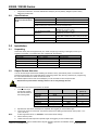
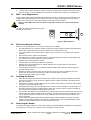
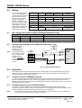
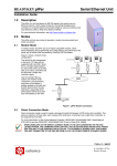
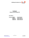
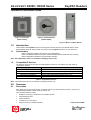
READYKEY K3000 / D8300 Series
KeyPAC Readers
Operation & Installation Guide
Figure 1: Low Profile
(K3001 / D8301)
Figure 2: Vandal Resistant
(K3002 / D8302)
Figure 3: Mullion (K3003 / D8303)
1.0
Introduction
These readers read KeyPAC ID-devices including ISO thickness ID cards. They do not read the earlier
K2000 / D8200 series ID devices. Make sure that you specify KeyPAC whenever you buy ID devices.
1.1
Part Numbers
K3001 / K3001W and D8301 are KeyPAC Low Profile Readers
K3002 / K3002B and D8302 are KeyPAC Vandal Resistant Readers (Stainless Steel or Brass)
K3003 / K3003W and D8303 are KeyPAC Mullion Readers
Note: The K3000 Series readers are available to Readykey Dealers only.
1.2
Compatible ID Devices
The KeyPAC range will not work with the older Readykey ID devices. The following are part codes for
compatible ID devices:
Part Number
K3011-10
K3011M-10
K3010-10
K3011WG-10 / D8339-10
3010WG-10 / D8338-10
Description
KeyPAC ISO Thickness Card (pack of 10)
KeyPAC ISO Thickness Card with Magnetic Stripe (pack of 10)
KeyPAC Tokens (pack of 10)
KeyPAC Cards with Wiegand Stickers (pack of 10)
KeyPAC Tokens with Wiegand Stickers (pack of 10)
Table 1: Compatible ID Devices
Note: The K3000 Series Devices are available to Readykey Dealers only.
2.0
Overview
2.1
Description
Each reader may be mounted internally or externally without any special weather protection, however the
Vandal Resistant Reader is better suited to outdoor use.
Other important features include:
•
•
•
•
•
Suitable for mounting on metallic and non-metallic surfaces
Integral red/green LED
Tamper protection
Low idle current consumption
Integral sounder (not Vandal Resistant)
17404 Ver 2.4/47556B
K3000 / D8300 Series
•
2.2
Output format selection. Formats available are Readykey format (default), Wiegand (26 and 34bit),
Magstripe and Barcode
Specifications
Appropriate Reading
Range for ISO Thickness
Card
Power Requirements
Environmental
K3001 Low Profile
0 in. – 4 in. (0 cm – 10 cm)
K3002 Mullion
0 in. – 3 in. (0 cm – 7.6 cm)
K3003 Vandal Resistant
0 in. – 2 in. (0 cm – 5.1 cm)
These ranges will reduce if the readers are mounted on surfaces containing
metal or if they are near local sources of electrical noise.
Mullion
12 VDC (nominal), < 40 mA;
Tolerance +10.5 V to +20 V
Low Profile and Vandal
12 VDC (nominal), < 85 mA;
Resistant
Tolerance +10.5 V to +20 V
Operating
-31ºF to + 140ºF (-35 ºC to + 60ºC);
0-90% RH at 86ºF±5ºF (30ºC ±2ºC) for 24 hrs
Storage
-31ºF to +176ºF (-35ºC to +80ºC)
Ingress Protection
Sealed to IP 66
Table 2: K3000 / D8300 Series Specifications
3.0
Installation
3.1
Unpacking
Check that all the parts are supplied with your reader. If anything is missing or damaged, contact your
suppliers immediately. The readers are each supplied with the following:
Low Profile
Mullion
Vandal Resistant
Two screws
Two 1” screws
Four Screws
Snap fit decor cover
Snap fit decor cover
Label
Label
Label
Ten cable crimps
Ten cable crimps
Ten cable crimps
MOV
MOV
MOV
Table 3: K3000 / D8300 Series Supplied Parts
3.2
Output Format Selection
You can set the output format before installing the reader or at any point before power is connected. The
instructions given here do not contradict those in the wiring section they are only necessary for programming
the output format before the reader is wired as normal.
The default output format for this unit is Readykey. To set the reader to other output formats:
Disconnect the power before starting. Failure to do so may damage the unit.
Start with all the wires disconnected from the reader.
1. To select the output
Output Format
format twist together
the wires as shown in
Normal power up
the following table:
Readykey
(default)
Wiegand 26-bit
Wiegand 34-bit
Magstripe
Barcode
2.
3.
Note:
4.
5.
Brown to…
Yellow to…
# of Flashes on
power up
all separate
white
-
green
white
green
green
green
white
Table 4: Output Format Selection
Separate the other wires and keep them separate. We suggest you use insulation tape.
0
1
2
4
5
Connect the power for 2 seconds. Connect the black wire to GND (ground) and the red to power +12 V
(10.5 V to 20 V).
At this stage there will be no indication of successful format change.
Disconnect the power.
Untwist the wires and keep them separate, again we suggest you use insulation tape.
K3000 / D8300 Series KeyPAC Readers Operation & Installation Guide
17404 Ver 2.4/47556B (7/01)
Page 2
© 2001 Radionics
K3000 / D8300 Series
6.
3.3
To check that you were successful, reconnect the power using the red and black wires (as above) and
count the number of green LED flashes. The format can be determined according to the table above.
MOV - Lock Suppression
A metal-oxide-varistor (MOV) is provided with each KeyPAC reader. This device prevents back EMF (high
voltage 'spikes') being returned from the electric lock to the unit. High voltage spikes can cause severe
damage over a period of time, and erratic operation of the system if not controlled.
Failure to fit the MOV at the lock will result in early failure of the unit. It will also invalidate the
warranty.
The MOV (A) should be fitted across the power
terminals of the lock (B).
+
A
A
B
Figure 4: MOV Installation
3.4
Before Installing the Reader
Be aware of the following when you choose the locations of your readers:
•
•
•
•
•
•
•
•
•
•
3.5
Installing the Reader
1.
2.
3.6
The cable distance from controller to reader should never exceed 3,000 feet (1000m) (with appropriate
cable). Also consider the maximum distance between the controller and the lock.
If you use a Request To Exit (RTE) switch, route the wiring so that it is not accessible if the reader is
removed.
Ensure that the LED is visible to the keyholder.
The best place for a reader is next to the door on the unhinged side at roughly the same height as the
door handle. Check local regulations for ADA compliance.
Readers may be located inside or outside.
Leave enough room behind the reader for the flying lead.
Readers can be mounted behind a non-metallic material, such as glass, plastic or wood without
affecting their reading range.
There should be a minimum 3 ft (1m) distance between readers (this includes in and out readers on
opposite sides of a door).
Readers can read in the same way from their back as they do from their front. Because of this, ID
devices may work from the other side of the wall on which the reader is mounted.
Avoid mounting the reader in direct sunlight.
Make sure the reader cable is not connected to the controller. Route the flying lead behind the reader
and connect it using the crimp connectors supplied. Wire the cable as described in the Wiring section
later in this manual.
If the connections are in a location that may be wet or damp, then protect the connectors with a sealing
compound, or use weatherproof crimps.
3.
Using appropriate fixings, such as wall plugs, for the surface you are mounting it on, fix the reader to a
flat surface using the screws provided. Install the reader onto a flat and even a surface as possible, as
this will reduce the possibility of it being levered from a wall.
4.
For the K3001 and D8301: the two holes are 2.4 in (60 mm) apart. Use the round hole first, then the oval
hole to ensure the reader is straight. Once the reader is mounted in place then the snap-fit décor cover
can be snapped into place. The hole in the cover should line up with the LED. Place the label on the
front of the reader.
5.
For the K3002 and D8302 Vandal resistant readers, apply a silicone sealant to any gaps behind the
reader to protect against moisture if the reader is mounted outside. User the Vandal Resistant screws
provided or other suitable fasteners. The LED should be at the top.
Removing the Reader
The K3001 and D8301 readers can be removed by placing a small flat-bladed screwdriver into the apertures
at the edges of the snap-fit cover. Take care not to damage the reader or cover.
© 2001 Radionics
K3000 / D8300 Series KeyPAC Readers Operation & Installation Guide
Page 3
17404 Ver 2.4/47556B (7/01)
K3000 / D8300 Series
4.0
Wiring
All connections are made to
a 3 ft (1 m) flying lead. 10
cable crimps are included for
joining connectors to the
cable from the controlling
system. Cable gauge
depends on distance from
the door controller to reader.
When using 0.22 mm² (24
AWG) cable, you should
twist the wires together and
double them over before
inserting them in the crimp.
Flying Lead
Readykey
Wiegand
Controller
Black
White
Green
SIG
N/A
DATA1
DATA0
Brown
Yellow
Red
Blue
Tamper
Magstripe
Controller
GND
DATA
CLK
Barcode
Controller
SIGNAL
Not Connected
(Crimp)
VCA / LED – GND to activate
Sounder – GND to activate
12 VDC (+10.5 to +20 V)
-V
Not Connected
(Crimp)
Table 5: Wiring Connections
4.1
Wire Gauges and Cable Lengths (Readykey Equipment Only)
7/0.2
16/0.2
32/0.2
Cable Gauge
0.22 mm²
24 AWG (0.6 mm)
0.5 mm²
20 AWG (1.0 mm)
1.0 mm²
18 AWG (1.2 mm)
Distance (reader to door controller)
Up to 750 feet (250 meters)
Up to 1500 feet (500 meters)
Up to 3000 feet (1000 meters)
Table 6: Readykey Wire Gauges and Lengths
4.2
Standard Wiring Diagram for Readykey Controllers (only)
Door controllers to
KeyPAC readers.
Always refer to your
controller manual.
Note:
The Readykey K2200
series controllers allow
the connection of two
readers to each
channel, only if both
readers’ outputs are set
to Readykey output
format.
Sounder Switch
N/O
Reader
Door
Controller
Door Contact
N/C
-V or GND
SIG
DC or DR1
RTE or DR2
LED
+V
Yellow
Blue
Black
White
Brown
Red
SOUNDER
TAMPER
0V
SIG
VCA/LED
+12V
N/O
Request to Exit
Figure 5: Standard Wiring Diagram
5.0
Operation
The reader LED will normally be red when the door is locked. When a key is presented within range of the
reader, and the key is valid for that door at that time, the LED will go green and the lock will release. The
LED will stay green while the lock is released.
5.1
Tamper Protection (Readykey format)
To ensure complete tamper protection the DR1 or DC terminal of the door controller should be connected to
the blue lead of the reader. If a door contact is being used then this should be connected in series with
DR1/DC and the blue lead. See the door controller installation manual for full details of how to set up tamper
protection and alarm monitoring.
5.2
Sounder Operation (not Vandal Resistant)
The internal sounder will operate if the yellow lead is grounded. The sounder will continue until the
connection to ground is broken. A relay, such as provided on the Readykey K2200 series controllers, may be
used to provide this operation under various conditions, e.g. Door Left Open.
Note:
The yellow wire is retained for the vandal resistant reader to allow the installer to set the output format.
ID devices will not be read while the sounder is operating.
© 2001 Radionics, a division of Detection Systems, Inc.
PO Box 80012, Salinas, CA 93912-0012, USA
Customer Service: (800) 538-5807
17404 Ver 2.4/47556B
Operation & Installation Guide
7/01
K3000 / D8300
Series
Page 4 of 4