1
-Rain
G
Mot~ti’
RG
RGX240,
issu
E
EMU - GS0068
q
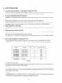
CONTENTS
Page
1. SPECIFICATIONS
..........................................
2. PERFORMANCE
1
...........................................
2
2-1
Model
RGX180
......................................
2
2-2
Model
RGX240
......................................
2-3
Model
RGX240D
3
4
2-4
DC OUTPUT
3. FEATURES
.....................................
(RGX240,
RGX240D)
5
........................
..............................................
4. GENERAL
DESCRIPTION
6
of GENERATOR
........................
8
8
4- 1
External
View of Generator
4-2
RGX180
Panel .......................................
9
4-3
RGX240
Panel .......................................
10
4-4
RGX240D
5. CONSTRUCTION
5- 1
Panel.
..............................
and FUNCTION
Construction
12
12
13
19
...............................
........................................
5-2
Functions
..........................................
5-3
Description
of Generator
5-4
Change of Engine Parts
6. SAFETY
11
.....................................
PRECAUTIONS
Operation
.........................
22
.................................
.....................................
26
7. RANGE of APPLICATIONS.
...................................
27
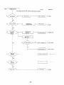
8. MEASURING
...................................
30
9. CHECKING
PROCEDURE
FUNCTIONAL
MEMBERS.
...........................
34
9- 1
Stator
Assembly
......................................
34
9- 2
Rotor
Assembly
......................................
35
9- 3
Brushes.
9-4
AVR
9- 5
Fuse Holder
9-6
9- 7
Receptacle
Voltmeters
9-8
9-9
Diode Stack Assembly ..................................
Primary Exciting Circuit
................................
10. DISASSEMBLY
36
...........................................
(Automatic
Voltage
and Circuit
Regulator)
Breaker
and REASSEMBLY
..............................
41
.............................
41
10- 2
How to Disassemble
10- 3
10-4
How to Reassemble ....................................
Control Box Check, Disassembly, and Reassembly
12-1
13. CIRCUIT
and Suggestions
41
...................................
.......................................
..............................................
Caster .............................................
DIAGRAM
39
39
39
40
and AC Plug .................................
and Pilot Lamp ...............................
Preparations
12.OPTIONS..
38
...........................
10- 1
11. TROUBLE-SHOOTING
36
........................
........................................
47
...............
55
56
60
60
61
r----r
,
RGX180
I
RGXZ40
I
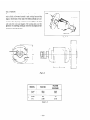
2 Pole, Single Phosc, Revolving-Fwlrl
50H7
6OHi!
50Hz
15oow
18OOW
2ooow
24OOW
13oow
1500w
1700w
2ooow
50H7
1lOV
11.8A
1lOV
13&A
1lOV
15.5A
22ov
5.9A
12ov
12.5A
?2OV
7.7A
23OV
b.7A
.-
230V
7.4A
24OV
5.4A
24OV
7.lA
11OV
(
12ov
2ooow
18.21-1
1 1 0 y/
16.7A
/’
Voltagv
WIthin
Atr-Cooled
4 Cyc!c,
* 7.7A
14.2$,
,,./
*’
7.1 A
_-
IOOW
Hcgulijtor)
3%
S~rtgltr Cylinder,
EYZOD
,
.._.
I
(Automatic
’
/“24OV
12V-8.3A
AVR
15.5A.i
/ 22OV
12OV/
_-
.
1.o
Robin
I
I
Self-Excltlry,
Not avir~lablu
I -I
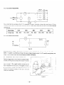
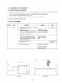
RGX240D
Gasol~rw
Engine
(Wl-186)’
183cc~11.17cu.1n.)
Max. Output
4.7 Ps/3600
Automohllt!
Fuel
F WI Tank Caf,ac~ ly
Rt?vnltl I lonlmln
50H7.3000
Ignltlon
SVSIWTl
Hohin
Stwtlrlg
SystRlrl
-_
)ry Weight
rpm, 60H7-3600
Solid State Ignition
Recoil
Ratio
1 .l Iltcl /Hr (5OHrj
1.3 litc!r/Hr
System
_.--.
1.3 IItw/Hr
1
_.
.-
_._
Height
552 mm (21.7
I
(5OH.z) 1.5 liter/Hr
in.)
(60H~)
--.
.__
377 mm 114.8 wt.)
482 mm (19.0
43 kg. (9.5 Ihs.1
rpm
Starter
(60H7)
Length
Width
Gwolinc
0.6 Ilters (1.3 U.S. plntsl
_.
Fuel Consumption
rpm
10 lrters 12.6 LJ.S. gal.)
Oil Capacity
hrrrcnsiorts
rpm, 4.0 Ps/3000
.--...
. .
in.)
.
-44.5
kg. (98 Ihs.)
*For U. S. A. and Canadian
markets
-
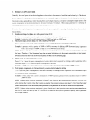
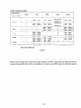
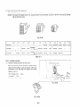
2.
PERFORMANCE
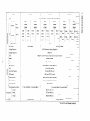
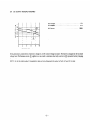
2-1
MODEL
Type
.
Power
Factor
Engine
RGX180
. . Self-Exciting.
_. . . . . . . . . .
2-Pole.
Single Phase
. . . . . . . . . . 1.0
. . . .
. . . . . . . . . EY20D
“(Wl-185)
I
- 1700
t
62
z”
61
“3
60
f
59
,”
58
Output
t 1500
5
Frequency.
1
’ 120
LO
..............
................
Voltage.
E
2
18OOW
...............
Rated
1
-13005
-1100
Max.
15OOW
60Hz
11OV
..................
r 900
I
I
3
I
1
6
9
1;
CURRENT
(Al-
l
15
I
53
I
- 1500
Output
t
z-
-1300
i
1100
Max.
...............
Rated
Frequency
f
k
2
C
15OOW
..............
.................
Voltage.
13OOW
50Hz
..................
220V
- 900
1.5
3
4.5
CURRENT
6
7.5
IA)-
Output
!
Max.
Rated
- 1500
Frequency.
t
- 1300 s
c
- 1100 2
Voltage.
...............
15OOW
..............
................
13OOW
50Hz
..................
240V
3
T
900 c
1
NOTE:
1.5
3
CURRENT
45
6
75
9
These characteristics
120V
IA) -
and 5OHz
the above.
-2-
are typical.
71OV or 230V
Those of 6OH.z
are similar
to
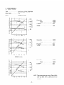
2-2
Type
MODEL
RGX240
Self-Exciting,
...............
Power Factor
Engine
..........
2-Pole,
Single Phase
1.0
..............
EY20D
“(Wl-185)
Output
- 2000
Max.
. . . . . . . . . . . . . . . 2400W
Rated
‘150 Iit( 3
I
‘1000
Frequency.
2
k
. . . . . . . . . . . . . . 2000W
. . . . . . . . . . . . . . . . 60Hz
Voltage
. . . . . . . . . . . . . . . . . . . 11 OV
Output
Max.
:
500
I
I
4
6
;I
10
12
-
CURRENT
14
16
18
20
(A)
I
53
2
t
52
5
51
E
50
’
EI
u
u
49
c 2000
Rated
17OOW
50Hz
..................
220V
230
- t 220
3
PJ 210
2
..............
................
Frequency.
Voltage.
. . . . . . . . . . . . . . . 2000W
500
200
I
123456789
CURRENT7
Output
.. 2000
Max.
Rated
-1 500
1000
250
/
240-
VC%TAGE
I
-3
z
f c
Frequency
Voltage
...............
2000W
..............
17OOW
.................
50Hz
. . . . . . . . . . . . . . . . . . . 240V
b
2
500
230
t
220
NOTE:
‘23456789
These characteristics
12OV and 5OHz
CURRENT(A)
the above.
-3-
are typical.
1 IOV or 230V
Those of 6OHz
are similar
to
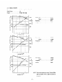
2-3
MODEL
Type
...............
Power
Factor
Engine
RGX240D
Self-Exciting,
2-Pole,
Single Phase
1 .O
..........
EY20D
..............
‘(Wl-185)
Output
Max.
. . 24OV-2400W
. . .
61
12ov60
59
1500
,
I
250
240
.-1000
Rated
3
12ov-
5
b
Frequency.
2
Voltage
1200w
x 2
. . . ~ . . . . . . , . 24OV-2000W
1ooow
. . . .
........
. . 60Hz
. . . . . . .
........
. . 12OV;24OV
x 2
230
500
t
I i I
0
2
4
CURRENT
6
8
1
10
(A)-
Output
Max.
. . . . . . . . . . . . . . . 22OV-2000W
11ov-2oooW
Rated
_ . . . . . . . . . . . . . 22OV-1700W
11 OV-850W
Frequency
Voltage
0
2
CURRENT
6
4
8
. .
x 2
x 2
. . . . . . . . . . . . . . . . . 50Hz
. . . . .
. . . . . . . . . . llOV:ll2OV
10
NOTE:
(Al -
These characteristics
1 lOV/22OV
to the above.
-4-
are typical.
and 5OHz
Those of 6OHz
120!/1/24OV
are similar
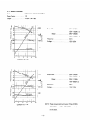
2-4
DC OUTPUT
(RGX240,
CURRENT
RGX24OD)
(A)
DC Voltage
............................
12V
DC Ampere
...........................
8.3A
DC Output
..........................
1OOW
-
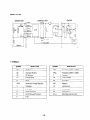
If the generator is connected to a battery to charge it, its DC output voltage increases. The battery is charged at the increased
voltage level. Performance curve @ applies to a caseunder a resistance load only; and curve @ represents battery charging
characteristics.
NOTE:
Up to the rated output
it is possible
to take out simultaneously
-5-
the output
of both AC and DC in total.
3.
1.
FEATURES
Lightweight, Compact
The Robin engine and revolving field generator designs provide added output poxer per weight and economical operation.
7.
Centralized Control
The witches. meters. and receptacles
are
located together on a large-sized control box. and all operating controls are
located on top of the engine for eas)-generator operation.
3.
Large IO-Liter Gas Tank
*IO-liter (2.6 LT.S.gal.) fuel tank is provided for nine hours of operation for Model RGSl8O and eight hours ior 1lodel
RGX240 (at the 5OHz rated output power,).
*The tank has a fuel gauge which shows the remaining amount of fuel m the tank.
4.
Solid State Ignition System
*Unlike the breaker point svstem. the solid state rgnition s>-stemhas no contact points so that maintenance
dur
to
point wear is unnecessary-and constant output power can be maintained ior long periods.
*Increased spark eners makes starting cask-.
5.
Extra-Quiet Operation
*X11 models are equipped with a large-sized. low-noise muifler.
*All models have a cl-clone type air cleaner of a low-noise, dustproof type.
6.
Small Voltage Fluctuations by XVR (Automatic Voltage Regulator)
The automatic voltage regulator wtomatisally
adjusts
th2
exciting current to hold voltage regulation down to
less
than 35. This helps prolong product life without dama-@ngthe electric devices.
7.
DC Output for Battery Charging (RGX240. RGX240D)
The generaror can generate a DC output ( 13.. lOO\V) whtle generating an XC output so that batteries <an be charged
during XC operation. In this case,make sure that the total XC and DC output does not exceed the rated output.
8.
Dual Voltages are Available on RGX240D.
* -4 du-alvoltage type lvhich supplies AC voltage is available.
9.
Output Voltage Waveform Close to Sine Wave
The output voltage a-aveform is close to a sine wave and is free of surges so that the load w-ill not be damaged
10.
Resistant to Inductive Load
Exiting
poner is obtained tram the sub coil which is wound apart irom the main coil. This means less output roltage
fluctuations against load variation. and thus a stead!- level ofpawer. This feature is efiective partrcularly for induction
motors. for example. kvhich are subject to sharp current variation.
11.
1005 Copper Windings
The windings are made onI>- of copper having lon internal resistance. This feature also helps improve generator effimien+ and prolong generator
lif2.
-6-
12.
Easy Starting with Recoil Starter
13.
Circuit Breaker for Troublefree Operation
14.
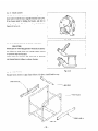
Ruggedly Built Frame
The box type frame is so ruggedly built that two or more generators can be stacked. Another convenient feature of
the Robin generators.
15.
A Caster Type is Optionally Available.
-7-
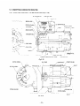
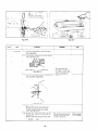
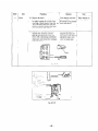
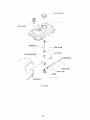
SPEED
CONTI301.
CONTROL
BOX
LEVEH
\
FUEL
CHOKE
KNOB
STOP
BUTTON
FUEL
TANK
GAUGE
imd TANK
CAP
SPARK
I
PLUG
1
,
, , .I,’
/
i
GENEHATOR
FlJEI
/
FlJEl
COCK
I
S~~-~AINEH
AlI{
I
CLEANLIt
/
MUFFLEt
HUBBEH
\
MOUNT
I-iECOlL
STARTEt7
tiANDLE
OIL
GAUGE
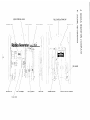
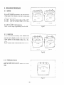
4-2
RGX180
4-2-l
1 lOV,
PANEL
120V
/../CIRCUIT
NEON
LAMP
BREAKER
AC RECEPTACLE
1
i
‘dc
vi
“.
! ‘k..
I
I
FUEL
COCK
/
EARTH
4-2-2
220V.
CIRCUIT
(GROUNDI
TERMIN/AL
FiJEL
STRAINER
23OV, 240V
BREAKER
\
AC RECEPTACLE
/
NEON
LAMP
FUEL
COCK
1
/
EARTH
fGROIJNDl
TERMINAL
FUEL
_- 9 -
STRAINER
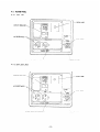
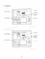
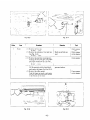
4-3
RGX240
4-3-l
1 lOV,
CIRCUIT
PANEL
120v
BREAKER
VOLTMETER
,
DC FUSE
-
DC OUTPUT
TERMINAL
,,
AC RECEPTACLE
.LOPEN,
1 -
/’
EARTH
4-3-2
,
!GROUNDI
/
1
FUEL
10A
COCK
;/i
;
FUEL
TERMINAL
STRAINER
22OV. 23OV, 240V
CIRCUIT
,
VOLTMETER
/
DC FUSE
-
DC OUTPUT
TERMINAL
,
FUEL
BREAKER
AC RECEPTACLE
10A
1 \
/
,,‘.
,’
EARTH
(GROUND1
TERMINA;
FUEL
-10-
STRAINER
COCK
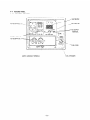
4-4
4-4-l
RGX240D
PANEL
llOV,‘22OV,
12OV,‘24OV
VOLTMETER
AC REC’IPTACLE
r-
CIRCUIT
BREAKER
2
-!,
DC FUSE
10A
I ON OFF
-DC
OUTPUT
TERMINAL
DC FUSE iOA
CIRCUIT
BREAKER/
AC RECEPTACLE
l-
FUEL
\
EARTH
IGROUND)
TERMINAL’
FUEL
-11-
STRAINER
COCK
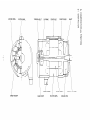
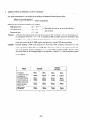
STATOR
COMPL.
ROTOR
COMPL.
THROUGH.BOLT
SLIP
RING
COVER
-_
.-
I
BOLT
FRONT
SHAFT
COVER
__
.--
;s
I
RUBB’ER
BRUSH
HOLDER
REAR
COVER
MOUNT
RDTOd
STATOR
COMPL.
COMPL.
COOLING
ENGINE
FAN
P.i.0.
SHAFT
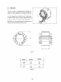
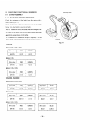
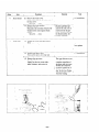
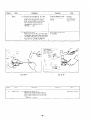
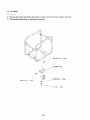
5-2
FUNCTIONS
5-2-l
STATOR
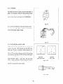
The stator consists of a laminated silicon steel sheet core,
copper wire which winds the core, and lead wires which deliver the power. The copper wire is wound into the main
coil. sub (.ausiliary) coil, and DC coil. XC output power
is taken from the main coil. and DC output power from
the DC coil. (DC coil is installed on Models RGX240 .md
RGXIOD
only.) The outside diameters and laminated core
thickness of various models are as show below.
Fig. 5 I
Fig. 5-2
MODEL
RGX240
RGXISO
60
2.36
Table 5 1
- 13 -
RGX240D
70
I
2.76
I
5-2-2
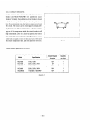
ROTOR
FAN
The rotor consists of a laminated silicon steel sheet cover
with a iield coil wound arcund it and cooling fans and slip
SLIP
rings at both ends of the shaft. The field coil leads are connected to the slip rings and direct current (DC) to the field
coil turns the rotor and magnet. The cooling fans cool the
generator by drawing cooling air from the slip rings and discharging it through the fans.
BEARING
’
Fig. 5-3
I’
c----l---II-
Fig. 5-4
MODEL
d
(mm)
(In.)
I
(mm)
(in.i
RGX240
/
RGX180
i
,
99.6
3.92
99.6
3.92
60
2.36
70
2.76
Table 5- 2
-14-
RGX240D
RING
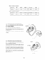
5-2-3
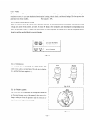
BRUSHES
An exciting current is supplied from the AVR to the rotor.
The brushes are made of carbon, and the brush-holders of
plastic. It is necessary to keep the contact pressure between
the brushes and slip rings within specitic limits. Thus. care
must be taken about brush length. (See 9-3 BRUSHES.)
Fig. 5-5
5-2-4
AVR
(AUTOMATIC
VOLTAGE
1
REGULATOR)
The automatic voltage regulator employs an electronic circuit to automatically regulate voltage.
L
J
Fig. 5-6
5-2-5
VOLTMETER
and PILOT
LAMP
__
Models RGX340 and RGX21OD hav-e a voltmeter that
comes in t\vo t>-pes: 15OV maximum tppe and 3OOV maximum type. The tl-pe of voltmeter indicates generator out-
~-::,i;--
put voltages. The generators with a generated voltage of
11OV or 13OV and dual voltage type use the 15OV msimum
’
t!-pe voltmeter: and those of 22OV. 23OV and 24OV specifications use the 3OOV maximum type voltmeter.
Model RGXISO employs a pilot lamp. The lamp hghts
when a voltage is generated. The pilot lamp also comes in
1
:
15OV MAX.
(llOV,
12OV)
300V MAX.
i22OV. 23OV. 24OV)
Fig. 5-7
(1)
two types: 12% t>-pe and 3OV type. These t>-pes are
selected to suit generator output voltage.
Fig. 5- 7 (11)
- 15-
5-2-6
CIRCUIT
BREAKERS
Models RGX180 and RGX240 have a pushbutton circuit
breaker and Model RGX240D
two pushbutton
circuit
1
breakers. Nomrallp, the pushbutton circuit breaker is closed
with the button pushed into the panel to keep the circuit
:
live. If an overcurrent runs. the button comes out to break
the circuit. The circuit can be closed again by simply pushing the button in. The circuit breaker is a thermo-sensitive
i
type so. if the temperature inside the circuit breaker is still
high immediately after the circuit has opened, the button
may not be able to be pushed in to the ON position. or ma>-
1
come back out again at once. In that case, wait a while until
Fig. 5-8
the inside temperature falls. and then push the button in.
Circuit breaker capacities are as follows:
1
Model
Specification
RGX180
RGX180
11ov. 120v
,
22OV, 23OV. 240V
Circuit Breaker
Capacity
’
Quantity
per Unit
15A
’
1
1
8A
I
RGX240
1 lOV, 120v
20A
RGX240
220V. 230V. 240V
10A
1
RGX240D
11 Ol22OV. 12Ol24OV
10A
2
Table 5-3
- 16 -
1
5-2-7
FUSE
The fuse prevents DC output overcurrent and short<ircuir overcurrent. Ii the generator is operated at a level exceeding the
maximum current. it can cause insulation deterioration. ‘curninp. electric shock. and electric leakage. The fuse protects the
generator from these troubles.
5-2-8
RECEPTACLE
Fuse capxiry:
10.1
and AC PLUGS
These are used for raking XC output power from the generator. A total of rhree kinds of receptacles, each var)-ing in rated
voltage and current from another, are used. As man; XC plugs as the receptacles. each matching the corresponding receptacle. are provided. Table 5-4 shows the rated current for each receptacle. Be careful not to use the receptacles and XC
plugs beyond the specified limits to prevent burning.
Fig. 5-4
5-2-9
TERMINALS
The terminals are for producing DC output power. and
I
RED
BLACK
come in two colors. red and black. The red one is $ositive
I + 1. and the black one negative I - )
1
Fig. 5- 10
5-2-10
FRONT
1
COVER
I
Ths front cover 1s dn alummum die CastmEand is mow-ted
on the mam besrmg cover
ai
the ensns. It has \~entsto dls-
charge ;oolmg dir from the generator anil the vents are Lesigned to pwent fingers from entering.
I
Fig. 5- I 1
- 17 -
5-2-11
REAR COVER
The rear cover is also an alumrnum die casting. and has a
faucet joint to hold the stator together w-ith the front cover.
It has bosses inside for holding the brushes, and slits for
taking cooling air in. The slits are so designed that htrman
fmgers will not go in.
Fig. 5- 12
I
5-2-12
RUBBER
MOUNTS
(RUBBER
VIBRATION
ISOLATORS)
Rubber pads for controlling generator vibration and dislocation. These are made of the most suitable rubber material
to optimum shape and hardness.
Models RGX180. RGX240. and RGXI4OD in particular
use diagonal support rubbers to reduce vibration.
I
1
Fig. 5- 73
5-2-13
PIPE FRAME
The pipe frame consists of a pipe frame skeleton. side plates X and B and box stak-.
SIDE
PLATE
B
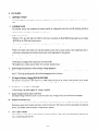
5-3
DESCRIPTION
5-3-l
REVOLVING
of GENERATOR
ARMATURE
OPERATION
TYPE and REVOLVING
NO-FUSE
FIELD
TYPE
CONTROL
I
AC VOLTMETER
\
BREAKER
‘....
\
\
BOX
NEON
/
LAMP
1
SOCKET
PLUG
FRONT
YOKE
.<‘G
---+---
POLE
ENGINE
FLANGE
ASSY
-FIELD
COIL
SHAFT /
ARMATURE
;
I
COVER
J!-kFT&f~‘zzz,
ASSY
FIELD
COIL
,
/
;)’
I I
’ 1 i
t’
’
ASSY
/
RUBBER
VIBRATION
ISOLATOR
ENGlNiE
SHAFT
;
COOLING
P.T.C 1.
FAN
Fig. 5- 15
ROTOR
COMPL.
~
\
SLIP
:
RING
COVER
,, FRONT
BOLT
ii
BRUSH
HOLDER
n
REAR
COVER
/
/
ROTO;
RUBBER
Fig. 5- 16
- 19-
I I
COOLING
/
/’
b&NT
STA’TOR
COMPL
COVER
FAN
COMPL.
ENGINE
SHAFT
P.T.6.
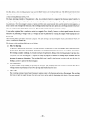
The RG Series 1sthe revolving armature type. and the RGX Series is the revolving field tk-pe. The differences between these
types and then features are described below. The constructron of the revolving armature t>-pe is shoxn in Fig. 5 -15. and that
of the revolvmg field type in Fig. 5 -16.
The basic operating principle of the generator is this. As a conductor moves in a magnetic flus (between poles S and S of a
magnet). a voltage is generated in the conductor and can be taken out as electric power. Generally. an electromagnet is used
for generators. The ele.ztromagnet consists of poles and field coils wound around them, and the poles become magnets as a
direct current runs through the field coils. The revolvtig armature type has static poles and a revolving armature which consists ot‘ a conductor for taking electric power out. The revolution of the armature generates a voltage.
It was earlier explained that a conductor moves in a magnetic flux. Actually, howev-er. a relative speed between the two is
sufficient for generating a voltage. That is. a voltage can also be generated bl- rotating the magnet while keeping the conductor still.
The revolving field type falls in the latter categor!-: The pole serving as an electromagnet rotates. and armature ivhich consists of a conductor remains still.
The features of the revolving field type are as follows:
a)
Only two slip rings
AS generator applications diversified! it became necessary for generators to meet increasingly varied conditions involving XC output. DC output, dual voltage, three-phase, and usefulness with induction motors. Accordingly. AC windings.
DC windings. auxiliary windings, etc. became necessary for generators. Becausethe revolving armature type takes elecrric power from the revolving part. it requrres as many slip rings as the number of winding output termmals. and this
increases the generator dimensions. The revolving field type is small in size because it requires only two slip rings <or
feeding a current to operate the electromagnet.
b)
Easy maintenance
As man)- brushes as the number of slip rings are necessary. The revolving field type is easier to maintain than the revolving armature type because it has fewer slip rings and brushes than the latter.
Cl
Lightweight
The revolving armature type is heavT because it requires yokes to fix the poles and serve as tlus passage.The revolving
field type is light in %-eight because the stator and rotor can be made by laminating steel sheets of the same material.
- 20 -
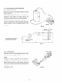
5-3-2
PRIMARY
EXCITING
ACTION
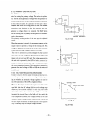
The RGX Series employs an exciting coil in the engine magneto for raising the primary voltage. This action is explained. The RG Series generates a voltag2 when the generator IS
started again because of the residual magnetism remaintng
FC
in the yokes and poles. If a generator of this type is disas-
r-----1
I
sembled and stored for a long period of time. the residual
magnetism. may dissipate so that the generator may not
rc&
generate a voltage when it is restarted. The RGX Series
;
has an exciting coil for primary exciting action to eliminate
1
I
$EC;
I
I
L-----J
such a phenomenon.
ENGINE
The primary exciting action of the new type is explained
MAGNETO
Fig. 5- 17(A)
below.
When the generator is started. th2 permanent magnet on the
2ngine rotates to generat a voltage in th2 ssciting coil. This
voltage is regulated by a diode in the .AVR to f22d a current
to the generator field coil (FC). (See Fig. 5-l 7(A).)
MC
4
The rotor is turnsd into an electromagnet by that sun-ent
and rotates so that voltages are generated in ths stator coils
(main coil, sub coil: and DC coil). The voltage generated in
the sub coils is operated by th2 .AVR to f22d a current to increase the field co11current (See Fig. 5-17(B).) As a result.
the rotor magnetism increases. This operation is repeated to
SC
FC3
E
AVR
generate the rated voltage at 50~~ or 6OHz in the main coil
and DC coil.
5-3-3
VOLTAGE
Fig. 5- 17(B)
REGULATING
MECHANISM
Connect a load to the AC output terminal and increase current. Output voltage varies as shown in Fig. 5-17(C) depending on whether an automatic voltage regulator is
used
or
not. The operation of the AVR is explained below.
WITHOUT
When an AC output is taken, the engine is loaded and its
RATED
rpm falls. Also the AC voltage falls due to the voltage arop
caused by the internal resistance of the coils.
The
XVR
detects this voltage drop and its built-in SCR automatically
VilTH
AVR
increases the current flows to the field coil. As a result, the
rotor magnetism increases. th2 voltag2 lowered b>-th2 .oad
current is raised. and the output voltage is kept constant. If
-A
the AC output is reduced. the SCR operates in the opposite
way to similarly keep the output voltags constant.
Fig. 5- 17(C)
-21-
AVR
VOLTAGE
5-3-4
DUAL
VOLTAGE
TYPE (RGX240D)
The dual voltage t)-pe can generate two Foltages from a single generator. It comes in two varieties: 12OV~‘11OV and
1lOV!ZOV.
The circuit is shown in Fig. 5-l 8.
Each of MC1 and MC2 generates an AC 12OV (or 1lOV)
with the same phase, which is one half the rated output
I
voltage. This model has two receptacles to output one half
of the rated voltage from each of the receptacles (112OVor
Fig. 5- 78
1 lOV,.
MC1 and MC2 are connected in series to each other so that
the rated voltage (21OV or 21OVj can be obtained from the
receptacles. (See Fig. 5 - 19 .)
240 (22O)V
Fig. 5- 19
5-4
CHANGE
of ENGINE
PARTS
For details of the engine. please refer to the EYZO service manual. The RGS Series ?mplgs engine parts specia! to the
RGX to suit the modified engine. The engine parts can be classified b>- ignition system. control system. fuel system. and
cooling system. The engine parts fur each of these systems are explained belox.
5-4-l
IGNITION
SYSTEM
RGX Series employs a solid state ignition system (T.I.C.). Please rcfcr to the section on Robin Solid State Ignition Engine in
the EYl5. EYlO Service Manual.
All models use a primary exciting coil of especial performance and lead length.
NOTE:
Be careful
not to use an excitingcoil
of different
performance
- 22 -
because itcan
damage the automatic
voltage regulator.
5-4-2
CONTROL
SYSTEM
The control parts are certainly located to permit centralized control at the top of the engine. The parts added or changed
are as shown in Fig. 5 -20.
SPRIVG
WASHER
NUT
\
\
PANEL
CP. 2
WIRE
1 CP.
WIRE
2 CP.
STOP
BUTTON
KNOB
/
CONTROL
ROD
NUT
e
BRACKETCP.2
SPEED
GOVERNOR
LEVER
CONTROL
SCREW
Fig. 5-20
-23-
CONTROL
SPRING
5-4-3
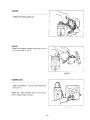
FUEL SYSTEM
The large-sized IO-liter fuel tank is mounted in the frame.
The fuel piping was changed as a result as shown in Fig. 5-Z 1.
TANK
FUEL
GAUGE
HOSE
.g
/--A
^&
CLAMP
fo CARBURETOR
HOSE
BANJO
FUEL
Fig. 5-21
5-4-4
COOLING
SYSTEM
-4 baffle is provided to prevent engine cooling air from rais-
AIR GUIDE
ing the temperature of otherparrs. X large siz2d rubber pip2
shown in Fig. 5 -21 prevents vapor lock even at high ambienr trmperature (up to about 13°C).
The air guide discharges the engine cooling air in the back of
the generator. A cylinder baffle with an opening is used to
improv2 air flow.
CYLINDER
BAFFLE
Fig. 5-22
- 24 -
STRAINER
CLAMP
5-4-5
CARBURETOR
The carburetor has an air vent and a rubber pipe to ensire stabilized performance at high temperature.
RU3BER
PIPE (to be connected
to AIR
VENT)
[085
10408
501
/
HOSE
CLAMP
CARBURETOR
1056 10800
ASSEMBLY
101
[227 62320
101
Fig. 5-23
5-4-6
OTHERS
The air cleaner and muffler were modified in shape, but are installed in the same way as before. The air cleaner element is
the same as the one used in the cyclone type.
MUFFLER
AIR CLEANER
Fig. 5-24
- 25 -
COVER
6.
SAFETY
PRECAUTIONS
1.
Use extreme caution near gasoline. A constant danger of explosion or fire exists.
Do not fill the fuel tank with gasolin u-hi12 the engin is runmng. Do not smoke or use open tlame near the fuzl tank.
Be
2.
car2ful not to spill fuel when refuueling.Ii spilt. wipe it and let dry before starting the engine.
Do not place inflammable materials near the generator.
Be careful not to put gasoline. matches. cwnpowd2r. oil cloth. straw. trash or an>-other inflammables near th2 gsnerator.
3.
Do not operate the generator in a room. cave or tunnel. Always operate in a well-ventilated area.
Otherwiss the engme may become overheated and also, the poisonous carbon monoxide contained m th2 exhaust gases
will endanger human lives. Keep the generator at least 1 m (4 fset) away from structums or facilities during
4.
use.
Operate the generator on a level surface.
If the generator is tilted or movzd during use. there is a dangsr of fuel spillage and a chance that the gensrator ma>-tip
5.
over.
Do not operate with wet hands or in the rain.
Severe electric shock may occur. If th2 generator is moistened by rain or snow. wipe it and fully drk- it before starting.
Don’t pout Lvater over the generator directly- or wash it tvith water
If the generator is wet with Lvater. th2 insulations will be adverssly affected and may cause current leakage and electric
shock.
6.
Do not connect the generator to commercial pow-er lines.
This may cause a short-circuit or destroy the generator. Use a transf2r switch for connzcting with indoor lviring.
NOTE:
The parrs numbers
of the transfer
365 45604
08
3674560508
3404560608
340 45608
and of the plastic
Part Name
Part No.
(
switches
08
’
box to store them are as shown in Table 6- 1.
; Phase
I_
O’ty
Allowable
Transfer
Switch
1
1
15A
Transfer
Switch
1
1
30A
Transfer
Switch
1
1
60A
1 Transfer
Switch
1
3
15A
Switch
1
3
30A
3484560908
;
Transfer
3674300808
:
Plastic Box
1
1.3
30A
3484300908
/
Plastic Box
1
1
60A
Current
Table 6- 1
7.
Use fuses of the correct capacity.
If th2 generator rpm is increased exorbitantly in the overload condition by using a fus2 in excess of th2 rated capaiitl-.
th2 gwerator could
CAUTION:
be
If the fuse is burned
be an overload
or a short-circuit.
and AC plugs for faulty
8.
burnt and the XYR 02 damaged.
out or the circuit
breaker
tripped
in such a case, stop operation
off when using an electrical
immediately
and carefully
check
appliance,
the cause may
the electrical
appliance
wiring.
stopping
In stopping the gensrator. turn the speed control lever to the low position to slow it down to idling speed. and th2n stop
it. If the generator is stopped suddenly from high speed. the sngiw may backfire.
- 26 -
7.
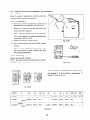
RANGE
of APPLICATIONS
Generally. the rat2d power of an electrical apphan<e oiten refers to the amount oi work that can be don2 b?- it. The electric
power required t?r operating an electrical apphance is not necessarily equal
Eiectri4
to the amount of work that can be done bk-it.
produ~rs generally ha\2 a lsb2L showing their rated voltage. irrequeniy. and polver consumption (input power!. The
polv2r consumption of an 2lectrical product is the power newssark for using it. Nhen using a generator for operating an
ele;tri<al product. hwe\er.
the po\ver factor and starting current must also be taken into consideration.
Determine th2 requir2d capacity of your g2nerator frown the
requirsd ior operaring electrical products that are classi-
power
lied as iollows:
incandescent lamps. hot plates. etc. with a power factor of 1.O
Total power consumption must be squal to or less than the rated output af the gen2rator.
Example: .A gsnerator with a rated output power ci TOOOKcan l@t ten TOON’lamps,
Fluorescent lamps. mercury lamps. etc. with a smaller power factor
S212~ra generator v-ith a rated output equivalent to 1.2 to 2 times the poser consumption of the load.
Example: ..I generator with a capacity oi 1OOK to 16OK is necessary for lighting a 8OW fluorescent lamp. A generator
Lvith a rated output of lOOOK can light six to ten 4OF fluorescent lamps.
NOTE:
Wattage
the lamp.
efficiency
of the fluorescent
Therefore,
should
lamp generally
if the fluorescent
be taken into
account
does not indicate
lamp has no special
as explained
in
the power
indication
consumption
as to the power
Item 5 on the following
but indicates
consumption
the output
or input
of
power,
page,
Electric tools. etc. that are driven by a motor
Po\ver 1.Z to 3 times the poRer consumption of a motor-driven tool is requrmd ior starting so select a generator with a
maGrnum output 1 .J to 3 times the power consumption of the load.
Example: .L\3OO\Vmotor-driven drill requires a g2wrator Lvith a maximum output of-IO0 to 9OOK or more.
Hater pumps. compressors. etc. that are driven by a motor w-hich is loaded at starting
3 to 5 tmr2s the power consumption of the load is nxessark- f‘or starting so select a generator with a ma.ximum output
3 to 5 tun2s its po\ver consumption.
Esample: X watsr pump \r-ith a po\ver consumption of 1OO\Vrequires a generator rvith a maximum output of 1’700 to
TOOOWor more.
NOTE
1: Motor-driven
when startmg
products
their motors.
power
consumption
NOTE
2: MO tar- driven
the kind
of motor
mentioned
in
Once their motors
so that the excess power
products
and start-up
mentioned
load.
Items 3 and 1 require
are started,
generated
rhe products
by the generator
the aforementioned
generator
consume
1.2 to 2 times their rated
can be used for other electrical
in Items 3 and 4 vary in their required
If it is difficult
to determine
with a larger capacity.
- 27 -
only about
capacities
the optimum
ma tor starting
generator
appliances.
power
capacity,
only
depending
on
select a generator
5.
Lhpplianceswithout any indication as to power consumption
Some appliances have no indication as to power consumption: but instead the work load (outpurj is indicated. In such a
case. power consumption is to be worked out according to the numerical formula indicated below.
(Output of slectrical appliance)
(Efficiency,l
= (Power consumption)
Efficiencies of some electrical appliances are as follows:
Single-phase motor
_. . _. .
Three-phase motor
0.6 - 0.75 -
. _ . . _ . . . . . 0.65 - 0.9 ~
-
The smaller the capacity. the wors2 the efficiency.
and dce versa.
Fluorescent lamp . . . . . . . _ . . 0.7 - 0.8
Example 1: X 4ON fluorescsnt lamp means that its luminous output is 4OK. Its efficiency is 0.7 and accordin&.
pow-
er consumption will be 40 - 0.7 = 5XV. As explained in Item 2. multiply this pow2r consumption value
of 57lV b>- 1.’ - 2 and you will get th2 figure of necessar>-capacity of a generator. In other Lvords. a generator with a rated output of lOOON-capacity- can li@t nine to fourteen 4017 tluorescent lamps.
Example 2: GeneraIl!- speakin,.0 a -lOON-motor means that its work load is -lOON-.Efficiency oi this motor is 0.7 and
power consumption Lvill be 100 +- 0.7 = 57OK. W12n this motor 1sus2d ior a motor-driven tool. the capacity of the generator should be multipled b>- 1.Z to 3 and 5701V as explained in Item 3. Moreover. when
this motor is used for the submerged pump or air compr2sser. it requir2s 3 - 5 times as powveriul a generator as in Item 4.
I
Model
I
Frequency
50Hz
Incandescent
lamp,
hot plate, etc.
Fluorescent
lamp,
mercury lamp, etc.
j
’
RGX240
RGX240D
I
RGX180
60Hz
50Hz
!
60Hz
1700~
1
2000~
1300w
15oow
about
850W
about
1ooow
about
11oow
about
13oow
about
850W
about
1 ooow
about
12oow
Motor-driven
tool,
general-purpose
motor, etc.
about
750w
Water pump,
compressor
about
350w
’
i
I
about
4oow
Table 7- 1
- 28 -
’
about
5oow
’
about
600W
NOTE:
1.
Wiring between
Allowable
generator
current
current
teriorate
2.
appliances
of cable
Use a cable with a allowable
input
and electrical
is higher
current
that is higher
than the allowable
the insulation,
possibly
burning
than the rated input
current
it out.
current
of the load (electrical
of the cable used, the cable will become
Table 7-2 shows cables and their allowable
appliance).
excessively
currents
If the
heated and de-
for yourreference.
Cable length
If a long cable is used, a voltage
to the load (electrical
produc
drop occurs due to the increased
t) decreases. As a result,
resistance
in the conductors
the load can be damaged.
so that the input
voltage
Table 7-2 shows voltage drops per
meters of cable.
Allowable
current
Nominal cross
section
Resistance
I
t
r
; No. of
mm:
!
1 25
7
I
12
1
23
2.0
3.5
r-5.5
17
~~~‘~
Current
Amp.
I
No.imm
A
.75
’
I
30;0.18
50i0.18
,
35
’ Ci,lOOm
1
37/0.26
70i0.32
I
’
I
3A
2.477
, 2.5V
1 8V
. .486
1.5v
5v
0.952
0.517
45:0.32
1A
1v
I
0.332
,
3V
-
1 .5v
-
1v
1
’
5A
I
8A
I
, 10A
12.5V
1
-
1
7.5v
5V
12A
;
15A
-
-
,
-
I 12v
:5V
, 18V
’
-
8V
a 1ov
12v
2.5V14V
!
2v
5V
2.5V
3.5v
, 6.5V
4v
Table 7-2
Voltage decreaseindicates as V = &
xRxIx %
R means resistance (LL’lOOm) on the above table
I means electric currznt through the Loire (.-A).
i-means the length of the wire (.rnj.
The length of the wire indicates round length. it means twice the length from generator to electrical tools.
-29 -
15V
I
7.5v
5v
I
j
!
100
8.
MEASURING
8-1
8-l-l
PROCEDURE
r
METERS
VOLTMETERS
XC and DC vo!tmeters are necessary. The approximate XC
voltage ranges of the voltmetsrs to be used for various types
of g2nerators are as follows:
0 to 150\-:
I
,
Type with an output voltage of I 10 or 13OV
0 to 3OOV: Tl-pe with an output voltage of X0. 230. or
:
‘4OV.
q
w‘
3)
FOR
AC
.n
.d
I
I
--?
FOR
DC
0 to ISOV. il to 3OOV: Dual \-oltage r>-pe
I
Ths DC x:oltmeter range is approsimately from 0 to 30V.
8-l -2
Fig. 8- 1
AMMETERS
AC and DC ammetsrs are necessan-. Xn AC ammeter lvith a
range that can be changed according to ths current rating of
a given generator is most desirable. (About 10-a. 20.4.
100 A)
The DC ammeter range is approximately from 0 to 15.4.
FOR
AC
FOR
DC
I
1
Fig. 8-2
8-1-3
FREQUENCY
METER
!
Frequency range: About 45 to 65Hz
NOTE:
Be careful
of the frequent
y meter’s
input
voltage
range.
I
I
Fig. 8-3
- 30 -
8-l-4
TESTER
Used for measuring resistance, etc.
Fig. 8-4
8-l-5
MEGGER
TESTER
Used for measurmg generator insulation resistance. Select
one lvith testing voltage range of SOOk-.
Fig. 8-5
8-l -6
TACHOMETER
There are various types of tachometers. such as contactless
i
type. contact
’
:ype.
and strobe type. The contact type can
CONTACTLESS
TYPE
i
be used only when the generator and engine have been disassembled. The contactless t>-pc is recommended.
I
I
CONTACT
TYPE
I
STROBE
Fig. 8-6
-31-
TYPE
8-2
AC OUTPUT
MEASURING
;a
TOACd/LE+@
LOA;
$))
Use a circuit like the one shown in Fig. 8-7 for measuring XC output. A hot plate or lamp Lvith a power factor of 1.Oma>be used as a load. Adjust the load and rpm. and check that the voltage range 1sas specified
in Table
5-1 at the
rated
amperage
and rated rpm
I
Voltage
108 -
range
220v
230V
218 - 225V
228 - 235V
120v
1lOV
Rated voltage
115V
118 -
125V
’
240V
I
238 - 245V
I
Table 8- 1
8-3
DC OUTPUT
MEASURING
Fig. 8-8
Switch the powr on. Khen 1.45R resistance is attached as a load. check that the voltage is within the 13 to 1 IL7 range.
NOTE:
charge.
8-4
If a battery
Control
is connected
battery
MEASURING
liquid
as the load, the output
level during
INSULATION
charging
voltage increases by about
to prevent
7 TO ZV, possibly
causing battery
overcharging.
RESISTANCE
Connect a meger tester to one of the two receptacle output
I
terminals and the ground terminal. then measure rhe insulaI
tion rssistanx.
An insulation resistance of 1 megohms or
more is nxmal.
(The original insulation resistance at the
I
time oishlpment from tht factor! is 10 megohms or more.)
1
Ji it is I?ss than 1 mqohm. disassembl? the generatnr and
measure the insulation resistance of the statOr. rotor and
cant;01 bc!x indi\!dual!~-.
..
Fig. 8-9
-32-
over-
l
STATOR
Measure the insulation resistance between the red or white
coupler from the stator and the core.
Fig. 8- 10
1
. ROTOR
Measure the insulation resistance between the core and
one of the slip rings of the rotor.
Fig. 8- 11
. CONTROL
BOX
t
I
I
Measure the msulation between the live parts and the
casing or grounded part. Close the no-fuse breaker inst.
then measure it.
An>- part ivhich has an msulation resistance of less thar. 1
megohm has a faults insulation. ivhich can cause elcxtric
shock or leakag2.
Replace such parts.
I
I
Fig. 8- 12
-33 -
9.
CHECKING
9-l
STATOR
9-l-l
FUNCTIONAL
MEMBERS
STATOR
ASSEMBLY
MEASURING
WINDING
RESISTANCE
Check the resistances of the leads from the stator Lvith a
tester (See Fig. o - 1.)
Check all the leads \\hich are shown b>- typ2 m the tables
belc?w- An> !ead which IS mxtive
NOTE:
is fault)-.
Testers are not so accurate
ror need not be taken
against
into account
the values shown
It is measured
that some margin
when reading
of er-
the tester
in the tables.
bv wheatstone
time, please care enough
bridge
in regularly.
In this
not to exist the con tact resistance.
Fig. 9- 1
l RGxl80
l 50Hz 22OV. 23OV. 240V
1
.50Hz
11OV
ai
.60Hz
11ov.
120v
ai
+RGX240,
.50Hz
RGX240D
22OV. 23OV. 240V
‘11
.50Hz
11OV
I
I
@j
.60Hz
11ov.
Wire color
BLUE
BLUE
0.3 II
120v
- 34 -
ASSY
l 50Hz 11 OVi22OV. 12OVf24OV
I
’
WHITE
1.15Q
l 60Hz 1 lou;22ou.
9-l-2
MEASURING
9-2
9-2-l
ROTOR
BLACK
I
“,“:y
1.15x?
- $1
!
12oui24ou
INSULATION
Refer to 8-4 MEASURING
I
,
RED
Wire color
RESISTANCE
INSULATION
ROTOR
RESISTANCE.
ASSEMBLY
WI-NDING
RESISTANCE
MEASURING
Check the resistance between the two slip rings with a tester. (See Fig. 9-2.)
The resistance is normal if it is an>vhere from 6 ohms to
13 ohms.
TESTER
Fig. 9-2
9-2-2
MEASURING
INSULATION
Refer to 8-4 MEASURING
9-2-3
CLEANING
SLIP
RESISTANCE
INSULATION
ROTOR
RESISTANCE.
f=-%
RINGS
The slip ring surfaces must be uniformly bright. Slip :-ings
showing black spots. excessive wear, or uneven wear must
be repaired. A stained slip ring lowers generator effi;rency
SLIP
RING
-\
....
\
and output voltage. Polish the slip rings with fine sandpaper
while turning the rotor until rough spots disappear. Care
should be taken not to touch the rotor ~011swith the sandpaper. (See Fig. 9 -3 .)
Fig. 9-3
-35-
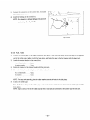
9-3
BRUSHES
The brushes must be smooth where they contact the slip
rings. If not. polish the brushes smooth with sandpaper. X
brush that is not smooth produces arcs between the brush
and slip ring leading to possible damage. Usable brush lengths
are from 5mm to ljmm
as shown in Fig. 9-3. .a brush
shorter than 5mm must be replaced because decreased con-
15mm
- 5mm
tact pressure between the brush and slip ring lowers generator efficiency and output voltage.
Fig. 9-4
9-4
AUR (AUTOMATIC
VOLTAGE
REGULATOR)
AVR trouble may be identified -by simply looking at the AVR, or by checking the inter-lead resistance with a tester. or actually mounting it in the generator and operating it.
9-4-l
AUR
TROUBLE
IDENTIFICATION
by APPEARANCE
If an AVR electronic part is burnt dark. or the surface epoxy resin melted, it often indicates .r\VR trouble.
9-4-2
IDENTIFYING
INTER-LEAD
AUR
TROUBLE
by CHECKING
RESISTANCE
Check the inter-lead resistance of the AVR with a tester.
(See Fig. 9 -5 .) If the tester readings vary greatly from the
values specified in the Table 9-I. rhe AVR is faulty.
NOTE:
Take tester inaccuracy
in to account
in reading
the tester.
TESTER
Fig. 9-5
- 36 -
MODEL
RGX305,
RGX305D
I
I
Tester polarity
i
Yellow
1
Red
1
One wire: OR
1
I
700K
Brown
I
-I
I
Yellow
Green
72K - 120KSl
- 1 MZ
65K - 10KC
Another:
00
One wire:
0.0,
Another:
m
j
7
400K
- 500KG
’
72K -
120KR
i
-
Red
-
I
-
White
Green
Brown
*Upper
250K-300KR
-
1
I 130K -
-
250K-300KC!
-
130K -
-
600K-1MR
-
SOOK - 500KS
-
’
’
-
I
-
140KC!
-
70K -
’
- 500KQ
m
220K - 250KR
;
- 50OKr1
40K-46KQ
-
1 250K
- 300K-r;
40K - 46K,o,
specifications;
50KR
45K - 50K!C?
7K - 9.5KR
1
I
lower
45K-
-
1lOKQ
400K
rows are for the 220, 230, 240U
, 400K
c.2
70K-llOK,c
!
- lOK,o,
00
140Kn
-
and the dual voltage
00
6%
!
6.5K - 8.5KS1
=
I
-
00
I
-
rows for the 110, 120U specifications
type.
Table 9- I
9-4-3
IDENTIFYING
AUR
TROUBLE
by MOUNTING
AVR
in THE
GENERATOR
and OPERATING
AUR
SCR or transistor damage cannot be detected by simply looking at the AVR or checking the lead resistances. Check it by
mounting the suspectedly faulty AVR in a normal generator, or mount a normal AVR in a generator which fails to generate
voltage.
- 37 -
9-5
FUSE
9-5-l
HOLDER
CIRCUIT
and CIRCUIT
BREAKER
BREAKER
Push the power switch on and check continuity. If current
flows, it is normal.
Devices such as that shown in Fig. 92 are necessary for
checking the circuit breaker if it properly operates. The
rated current is shown on the side of the circuit breaker.
Adjust the load switch until the ammeter reads about twice
the rated current marked on the circuit breaker. The circuit
breaker is normal if it turns off an)-where between 0.5 and
30 seconds.
Fig. 9-6
AMMETER
Commercial
power supply
a large-capacity
generator
or
--
Fig. 9-7
9-5-2
FUSE
FUSE
HOLDER
Check that a fuse is in the fuse holder and check its continuity with a tester. (-SeeFig. 9-g.) If it carries current. it is
normal.
If there is no current, take the fuse out and check it for
continuity.
If the fuse carries current. the fuse holder is
faulty. If the fuse carries no current, replace it with a fuse
of the correct capacity, and check the fuse holder again for
continuity.
Fuse capacity 1s 10.4.
Fig. 9-8
-38-
HOLDER
9-6
RECEPTACLE
and AC PLUG
Check the current-carrying parts of the receptacles and AC plugs and their leads and plastic parts for burns.
9-7
VOLTMETERS
and PILOT
LAMP
Apply AC voltage to a terminal and check if the voltmeter
AC
reads normal or pilot lamp lightens.
VOLTMETER
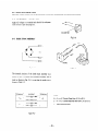
9-8
DIODE
STACK
Fig. 9-9
ASSEMBLY
--
IFig. 9- 70
The internal circuitry
Fig. 9- 7 1
of the diode stack assembly is as
shown in Fig. 9 -10. Check inter-terminal continuity with a
tester as shown in Fig. 9 - 11 to see that the results are as
shown in Table 9 - 2.
CURRENT
TERMINAL’
: TERMINAL
NOTE:
1-j
+
A --+---
6
C e
D Current
-
Table 9- 2
- 39 -
Check both
Current
flows from A (+-I to B (-1.
does not flow from
terminals.
C (+I to D l-1.
9-9
PRIMARY
EXCITING
CIRCUIT
As described m 5-3 DESCRIPTION
ERATION.
the primary exiting
of GENERATOR
OP-
coil is in the magneto
mounted on the engine. and the AVR has a circuit for it.
9-9-l
EXCITING
COIL
The normal inter-terminal reststance of the exciting coil is
about 10 to 30 ohms. Its voltage at the rated rpm is about
AC 10 to 3OV. Check the resistance and voltage with a tester to see if they meet these requirements.
9-9-2
OTHERS
30 output voltage from the genzrator.
Fig. 9- 72
If the trouble cannot be dztected by Step 9-9- 1 above. shsck the primary exciting circuit as follows:
.I\. Disconnect the control box and opersts thr gsnerator at the rated rpm. Dixonn2:t
th2 tRo k-2liow Lv-iresfrom th2 exit-
ing cot] to the XVR. and momentarily- ;onntlc‘t th2 positive i-i.1 an3 negatiw t -1 Isads of a 13’ batter>- m their ~1x2. Ii
no output voltag2 is generated. reconnect th2 battzr>- Gads th2 oth2r a-a!. Ii output l-oitage 1sgen2rated. th2 232iting
2oi! IS def22tive.
R. If no output voltage is generated by the test conducted as described in Step A.. operate the generator at the rated rpm and
momentarily connect a 1ZV battzrk- to th2 brush2s. Th2 green I2ad is posrtil2 (+.I and th2 black or brown lead n2gatne
(--I (Se2 Fig. 9-13.). If output I-oltag:. is gsnerated. the p:imdr~- exiting
AVR
Fig. 9- 73
-40-
ci:.xlt I~I th2 XL-R 1s def2ctive. R2nlac2 the
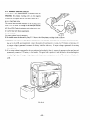
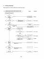
10.
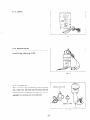
DISASSEMBLY
10-I
PREPARATIONS
1)
and REASSEMBLY
and SUGGESTIONS
When disassembling the engine ~ remember the locaticns of individual
ly. Ii you are uncertain of identify-ing
some parts, it is suggested that tags be attached to them.
2)
Have boxes ready to keep disassembled parts in groups.
3!
To prevent losing or misplacin,. o temporarily
4)
L’se the correct tools in the correct way.
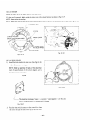
IO-2
assemble 2ach group of disassembled parts.
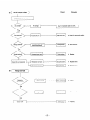
HOW TO DISASSEMBLE
-
Order ’
1
parts well so that they can be reassembed correct-
Item
I
I
1 FuelTank
I
Tool
-
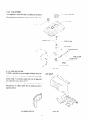
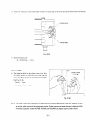
f 1) R2mov2 the front pan21. (See Fig. 10-l.)
40 screw
4 PCS.
-
( Zi Discharge th2 fuel.
Closz thr fu21 stramrr. rrmol-2 the cap.
place some v2sssI for gasoline undsr the
stranxr. and oprn the strainer to discharge ths fuel. I See Fig. 1OI
-. 2 )
( 3 r Dissonxct
ths iusl pipe.
ioosen th2 hose clamp on top of the
I
strainsr. and disconnect the he1 pip2
that connects the fuel tank to the fuel
strainer. I S22 Fig. 1O-3.!
!
t 4) Remove the fu21 tank bolts.
tS22 Fig. 10-4.1
6Q bolt
-t pss.
I
I
I
Remarks
Procedure
( 51 Remove the tit21 tank.
1 (+:I screwdriver
,
I
Absolutzly no smokmg.
, Cse a vsssel large enough
to recsivs the rrmaining
gasoline.
II
Appl> a drop of oil to
th2 nut on top of the
, strainer to smooth remoral.
I
1
’ ( -I screwdriver
!
13mm spanner or
’ box spanner
I
Be careful not to lose th2 ,
rubbrr washers located
, betwren th2 fuel tank
mountmg side plates.
I
-
Fig. 10-2
Fig. 10- 1
-41-
Fig. 1O-3
1
I
Order ’
Fig. 1 O-4
Item
1
[
!
Procedure
Remarks
Tool
I
2
/ Control Box
I
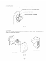
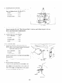
( 1 I Remove the grommet from the rear of
the control box.
1 (2)
Pull out the conmxtor
box. and take it ofi.
1
I
from the control
I
PUSH
PULL
-
-
PULL
Fig. 10-5 (I)
I
(3)
Remove the coupler that is connected to
the rear of the control box.
I
The <onncxtor and
coupler are so designed
YS to lock. so push and
pul! out as shown in
Fig. 10-s.
;
!
I 4 I Remove the fuel strainer.
Remove the nut on top of the fuel
strainer locatctd beside The control
box. ~See Fig. 10-6 I
( 5) Remove ths control box bolts and ths
control bos.
Rrmo\~-s the bolts from the frame and
box sta! (Se Fig. lo-- )
6~ bolt
4 2s
-42-
l4mm spannrr
I
Be car&l not to lose Th?
spacer betwvzen the control box and frame.
10mm spanner ]
or box spanner
Fig. 10-7
Fig. 10-6
-
I
Item
Order
-’
a
Frame
I
1
Procedure
Remarks
I. 1) Remove ths box sTa)-.
6~ -bolt
3 PCS.
Tool
1Omm spannsr
. 2 pcs.
I
( 2, Remove ths side platss. front and rear.
I See Fig. 10-8.~
60L bolt
-I pi..
! ! 3) Rzmovs th2 g2nsrator mounting nuts.
Remove the nuts that fast22 ths sngine
and rubber mount and the nuts that
fastsn the gsnsrator and rgjber mount.
8g nut . 3 pcs.
_--.
I 4) Remove the g2nsrator.
Lift th2 generator with a r.hain block.
and rsmox-2 ths framr. <SC-S
- Fig. 10-9.)
I 5) Rrmov2 thr rubb2r mount.
Turn the frame on its side. and rzmow
the nuT3 that fasten the rubber mounts
to the bottom of the frame
pzs.
-
1 Black spscial bolts are
used.
13mm spannsr
[
B2 car2ful about the
generator balance.
I
13mm spanner
! or box spannrr
8Qnut . 4
Fig. 10-9
Fig. IO-8
-- 43 -
/ 1Omm spanner
or box spann2r
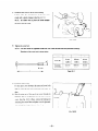
1 Order
1
item
!
I (2)
Remove the brush holders.
(See Fig. 10-10.)
Disconnect the terminals wired to the
brushes before removing the brush
holders.
56 screw
2 pcs.
I
5
Rear cover
,
sure to remove the
brush holders first be!
cause if the rear cover 1s
removed from the generator without removing
the brush holders. the
I brushes will break.
1 Be
i 1) Loosen the cover bolts and remove
them
4~ bolt.
3 pcs.
(2)
I
1Omm spanner or
box spanner
I
!
Remove the stator cover.
Turn up the stator cover edge and
remove the stator cover.
’ t.31 Remove the rear cover.
(See Fig. 10-l 1.)
Lightly tap the rear cover with a
plastic hammer. and remove it.
i. -) screwdriver
I
,
The type that uses a connectar does not permit
complete separation of
the stator and rear cover
because the connector
i cannot be pulled out of
the rear cover or grommet. In this case. simply
,
!
remove the rear cover
’ from the bearing.
Fig. 10-71
Fig. lo- 70
- 44 -
Tool
1 ( + j screwdriver
( 1) Remove the brush cover.
Remove the brush cover in the back of
the rear cover.
40 screw
. 2 pcs.
Brush holder
4
Remarks
Procedure
1
Order
1
Item
Procedure
I
-.
6
Stator
Tool
Remarks
, Sever hammer the windPlastic hammer or
i 1) Remove the stator.
(.-j screwdriver
ings and leads.
Puil out the stator from the front cover
Be careful not to peel the
by lightly tapping the outside of the
core with a plastic hammer. (See Fig. lo- ’ stator steel sheets.
I
11.) If the stator does not come out.
insert a screwdrive betaeen the front
I
cover and stator. and twist it.
I 2) Separate the stator and rear- co\-er.
Separate the connector ar d wire.
Push the terminal locks in the connector with a pin havmg a needle-like
sharp point. and remove the terminals.
(See Fig. lo- 13.)
It is not necessary to
separate the stator and
rear corer except when replacing the stator. rear
i
cover. or diode stack.
!
I
!
,
I
Fig. lo-13
-
.Fig, lo- 72
-45-
Order
-
/
!
Procedure
item
Rotor
( 11 Pull out the through-bolt. Fit a box
spanner or socket wrench orer the
head of the through-bolt. strike it
hard <ounterclockwse
with a hammer to loosen. and remove the
through-bolt. ISee Fig. 10-1-l.)
Remarks
Tool
If an air spanner is at-ailable, use it for easy- removal.
Hammer
Box spanner. or
socket wrench
I4m.m
I
100 bo:t . . 1 pze.
I.2) Remove the rotor.
Strike the rotor by the core with a plastic hammer. and remob-e the rotor from
the engine taper shaft. If the roror does
I
not come out. change its angle and
I
strike it again. (See Fig. lo- 15.1
Order
-8
t
Item
Front cover
1
Fig. lo- 75
Fig. lo-14
I
1 Sever strike the slip rings
! or windings.
Remarks
Procedure
i 1 I Remove the front colder.
Remove the bolts that fasten the engine’s main bearing cover to the front
cover.
80 bolt
3 pis.
- 46 -
Tool
13mm bo.x spanner
10-3
HOW TO REASSEMBLE
10-3-l
FRONT
COVER
Attach the front cover to the engine main bearing cover.
Match the faucet joint. and tighten the bolts.
89 x 18mm bolt . .1 PCS.
80 spring washer . 4 pcs.
Tightening torque 130 to 110 kg-m
NOTE:
Make
sure that
10-3-Z
ROTOR
the slits for cooling
air are down.
1) Clean the tapered part of the engine output shaft and
Fig. 70-16
the female tapered part of the rotor shaft of oil and
other forergn matter with waste cloth.
21 Install the rotor and tighten the through-bolt. (.See
Ftg. 10-17.)
Tighten the through-bolt by strikmg a box spanner
or socket wrench hard clockwise.
NOTE:
The outside
ness of the rotor
Paragraph
NOTE:
diameter
is shown
and lamination
in 5-2-2
ROTOR
thickunder
5-2 FUNCTIONS.
The through-bolt
is shaped as shown
below.
Fig. lo-17
n
I
Model
d
:
I
8mm
’
222 mm
’
8.74 in.
!
5
25 mm
RGX180
RGX240
RGX240D
i
5..16 In.
-
’
I
8 mm
5.‘16 in.
0.98 in.
230 mm
25 mm
9.06 in.
0.98 In.
(
Table lo- 1
-47
/
-
10-3-3
STATOR
Install the stator to tit the faucet joint of the front cwer.
If it does not fit properly. lightl>- strike the stator cnre \vltil a plasti,_ hammer as shown in Fig. 1O-19.
NOTE:
Never strike
the winding.
NOTE:
Make sure that the wires to the control
y.,
box areup
ta COYTROL
and that the wires to the brushes are to the back. (See Fig. 70-78.)
BOX
STATOR
:cj BRUiti
liOL%R
VER
I
STACY [
WIRES)1
I
I
Fig. lo-19
Fig. IO-18
10-3-4
REAR
COVER
1) Install the diode stackin the rearcover.(See Fig. 10-20)
39 x 12 mm screw. . . 1 pc.
NOTE:
meet
Solder
an assembly
the specifications
connector,
of leads, of the colors
of the circuit
diagram,
that
and a
to the diode stack.
DIODE
Fig. IO-20
L
The diode
Two
(5)
has markings
of input
( -J,
leads are blue; (+ J orange;
positive
and (-j
Fig. 70-21
3) Pass the wires Lvhich connect to the control b~,x from
the stator through the hole in the top of the rear co~r.
- 48 -
(-)
brown.
and negative
(-j,
on this side.
3) Install the rear cover to fit the rotor bearing.
Lightly
strike the circumference of the rear cover
evenly with a plastic hammer. (See Fig. lo- 22.)
NOTE:
the stator
Be careful
not
to pinch
the wires between
and rear cover.
Fig. lo-22
3)
Tighten the cover bolt.
NOTE:
The bolt
cannot
be tightened
unless the front
The shape of the cover bolt is shown
cover and rear cover are positioned
below.
RGX180
RGX240
RGX240D
I
1
d
Model
r=
correctly.
6mm
j
90mm
0.24in.
1
3.54 in.
6.3 mm
100 mm
0.24 in.
3.94 in.
Install the stator cover.
Fit the stator cover between the stator and cover bolts
until it covers all the cover bolts. and fold back -:he
edge.
Pass the wires out of the top of rear cover through the
grommet. and fit the grommet into the hole in the rear
cover. (See Fig. 10-X .i Then. reverse the bushing for
mountmg the control box and place it on the grommet.
The bushing has a larger diameter than the grommet.
Fig. lo-23
- 49 -
s
’
15mm
i
Table 10-2
,
1
I
0.54 in.
15mm
0.54 in.
7j
Insert the wires into the connectors.
The connrctor positions and wtr2 colors are shown in Table 10-J.
NOTES:
Terminals
3
through
c$ij for 0.75 mm’
‘z; and
cj,
@are
for 2mm’
wire, terminals
‘5,s.
for 1.25 mm’
wire, and .z~ through
wire.
Fig. lo-24
I
::z I/ 12; ’ .zj !
n
3
RGX180
-
-
RGX240
1 -
-
-
I
RGX240D
-
BLACK
I
i WHITE
1
RED
WHITE
RED
ORANGE
WHITE
RED
WHITE
WHITE
GREEN
WHITE
RED
i BROWN
I
I
BROWN
GREEN
-
RED
BROWN
GREEN
I
RED
-
1
I
Table 70-3
10-3-5
BRUSH
:.I.
II
hOLDER
1) Install the brtish holders in the rear cover.
Pass the mounting screws through ths brush holders,
push the brush holders SOthat the brushes w-111
be prr-
/
pendicular to. the slip rings. and tighten ths screws.
j
(Se2 Fig. lo-~5.j
I
.I
II
,I
,I
‘1
I
-
I
’
I
,.,
c
I
I
I
I
I
-Qslgmmscrew...?pcs.
50 washzr . 2 PCS.
5~ spring washer
2 pcs.
Fig. lo-25
Fig. lo-26
- 50 -
2 I Attach the connector to the brush holder. Connect the green lead to the stator side and the brown lead to the bearing
side.
GREEN
WIRE
Ficr. 7 O-27
3)
Install the brush cover.
49 x 10 mm screw . . 3 pcs.
10-3-6
FRAME
FRAME
1 I The frame has holes for the rubber mount locks. Hold
UPPER
the rubber mounts so their locks are in line with the
ho!es. and tighten the nuts on the bottom of the frame.
(See Fig. 10-28.)
8~ nut . .4 pcs.
8Qspring washer
-! pcs.
Fig. 10-28
NOTE:
The rubber
mounts
to use the rgbber
in hardness.
are so selected
mounts
Especially,
as to assure optimum
of the correct
models
RGX780,
parts number.
RGX240.
vibration
Rubber
mounts
and RGX240D
-51
-
depending
on model
may appear
use diagonal
and frequency.
Be sure
the same in shape but differ
support
rubber
mounts.
2> Install the generator in the frame.
Lift the generator with a chain b!ock. install it in the
Dame. and tighten the nuts. (See Fig. 10-29.)
8Qnuts.
. _ . . . . . . . .4pcs.
SQwashers . . . . . . . .-I pcs.
8~
spring washers . . . .-I PCS.
Fig. lo-29
3)
Attach the side plates to the frame.
&fount the side plate that reads “Robin Generator Model” to the front, and the blank side plate to the rear.
NOTE:
Use the black bolts for tightening
50 x 13 mm bolts
4)
them.
. . .8 PCS.
Attach thcr box stay to the side plates.
6ox 15mmbolts
. . . .Ipcs.
60 washer . . _
.Z PCS.
6o spring washer . _ . .2 PCS.
6onut
10 -3-7
...
CONTROL
. . . . . .2 pcs.
BOX
11 Fasten the control box to the frame and box stay.
NOTE:
Spacers must
controi
box.
be placed
the frame and
(See Fig. 10-30.)
68 x 15 mm bolts .
6~
between
washer . . .
6~ spring washer . . .
.3 pcs.
. .4 pcs.
4 pcs.
Attach the control box to the frame in sub-assembling
the control box.
Refer to Paragraph 10-4 for sub-assembling the control
I
I
-’
Fig. IO-30
box.
2) NYre the primary exciting crrcuit.
Connect the two yellow wires of the automatic voltage regulator in the control box to the exciting coil
wires of the en-tie, and clamp them to the control
box with cord bushings. t&e Fig. 10-3 1:)
INSERT
Fig. lo-31
- 52 -
3)
Connect the connectors to the control box. And push
the connectors into the control box.
4j
Install the bushing on the control box.
NOTE:
No clearance
and bushing.
is allowed
between
the grommet
(See Fig. 10-32.)
‘1 -
I-
Fig. lo-32
10-3-8
FUEL
TANK
1) Connect the rubber pipe to the engine carburetor and fasten it with the hose clamp. Attach the banjo to the opposite
end of the rubber pipe. tighten it with the hose clam?. and fasten the pipe to the fuel strainer with the banjo bolt.
3 I Attach the strainer bracket to the control box.
lox
10mmbolts
. . . . .2pcs.
4~ spring washer . . _ . .2 pss.
3)
Fasten the strainer to the strainer bracket with the joint nuts.
4)
Mount the fuel tank on the side plates with rubber washers between the t\vo.
6d x 20 mm bolts _ . . _ .4 PCS.
69 washers . . . . . . . .4 PCS.
60 spring washers . _ .
NOTE:
1 PCS.
For easy tank assembly,
glue the rubber
washers around
the holes in the side plates.
5) Connect the rubber pipe
First. fit the hose clamps on the rubber pipe. connect the strainer and fuel tank. then fasten the rubber pipe wth the
hose clamps.
NOTE:
Apply
a drop of oil to the rubber
pipe so that it may easily be connected
- 53 -
to the strainer
and the fuel tank.
FUEL
FUEL
TANK
HOSE
CLAMP
GAUGE
RUBBER
PIPE
4
STRAINER
I i
-’
BRACKET
RUBBER
HOSE
FUEL
/
BANJO
BOLT
Fig. lo-33
- 54 -
STRAINER
CLAMP
PIPE
10-4
CONTROL
10-4-l
BOX
CHECK,
DISASSEMBLY,
and REASSEMBLY
CHECK
Check the wiring bp removing the control box from the
frame and taking the panel B (rear panel) off,
10-4-2
DISASSEMBLY
1) Remove the control box panel B (.rear panel) and the
front panel from the control box. (See Fig. 10-34.)
2)
Remove the connectors from the control box, and
the wires from the connectors.
NOTE:
with
Push
the
terminal
a long, pointed
remove
them.
pin
locks
in the connectors
to unlock
the terminals,
and
(See Fig. 10-35.)
3)
Remove the automatic voltage regulator.
4)
*After disconnecting the wire from each part, remove
Fig. lo-34
the parts.
NOTE:
their
The DC fuse and the full power
wires
soldered
to them.
first, and then remove
10-4-3
Unsolder
switch
have
their
wires
9
them.
PUSH
C
REASSEMBLY
Keverse the disassembly procedure.
NOTE:
The wires are colored
for identification
PUSH
--I
of capacity
and gauge. Be sure to use the same wires when disconnected.
Fig. lo-35
NOTE:
Terminals
wire, terminals
through
3
through
i m? are
L'd
,$land
j-j;.
for 1.25 mm’,
g
are for2mm’
and terminals
z
@ are for 0.75 mm’.
Fig. lo-36
I
:@
MODEL
RGXl80
-
-
,T,
d
-:-
I
RGX240
BROWN
WHITE
1
ORANGE
WHITE
BROWN
GREEN
WHITE
RED
BROWN
’ GREEN
WHITE
RED
RED
-
-
BROWN
WHITE
ORANGE
WHITE
WHITE
RED
-
-
I
-
I
RGX240D
RED
i
BLACK
BROWN
I
Table 10-4
- 55 -
GREEN
8 WHITE
RED
I
-
-
11.
TROUBLE-SHOOTING
When rhe generator is in trouble. carefully check the trouble and remed)- IL
(11
( Voltmeter
1
does not work or pilot lamp does not light.
1
I
Voltmeter
or pilot
lamp is defective
Wrong wiring or some
leads unconnected
y
(Remedy)
(Cause)
I
Primary
Exciting coil
defective
0
Replace.
l
Wire correctly.
l
Replace
7 OK
.
exciting
Replace
AVR.
Resistance outsrde
range of 5 --7.5R
I
>
l
Clean, replace.
0
Check,
l
Replace.
Main coil broken
.
Replace
stator.
Sub coil broken
l
Replace
stator.
Replace
AVR.
qy-Eq
(Check
winding
replace.
resistance.)
I
Field coil shorr
range of 5 -7.5-Q
(See the description
resistance in 9-l .I
resistance
of winding
in 9-l .I
AVR
- 56 -
broken
l
coll.
(Cause)
&+x+
See (1) Voltmeter
Fuse burnt
out
(Remedy)
does not work.
.
Check for cause and replace.
OK
Characteristics
faulty
Wrong
wiring
.
Wire correctly.
Diode
broken
l
Replace.
.
Replace
stator.
l
Replace
ctator.
0
Adjust.
DC coil broken
Rpm unadjusted
0 Wire correctly.
OK
f
Check
AVR
AVR
- 57 -
broken
c
Replace.
(4) (
Voltage too low
I
J
If AC voltage
(Remedy)
Uhusel
is less than 1OV. voltmeter
needle should
not deflect.
Rpm unadjusted
Adjust.
I
OK
Wire correctly.
1
Wiring
checked?
loose wire joints
Wrong
wiring
Adjust.
1
;OK
i
than
Replace
Field coil shorted
4f2
rotor.
I
Clean, replace.
OK
OK
Check,
Brush defective
*-
----+
Main co11 shorted
replace.
.
Replace
stator.
l
Replace
stator.
!OK
AVR
- 58 -
broken
.
Replace.
/
’
Off-load voltage is normal,
(Remedy)
(Cause)
but load cannot be
Adjust
Change load.
jOK
IOK
AC plug crecked
for shortcl-cult!
Correct.
AC plug shorted
1
I
L
I
L__1
Resistance
‘IsI
Loadshorted
infinite
Check and correct
1
load.
I
Correct.
Charge
Load defective
!
FUo-Fuse breaker.
Check and correct
l
load.
1
l
Replace.
Check.
Clean.
Check.
: Net cnecked properly.
Or, opera;lon returns to norm21 byhen AVR
is replaced with anorhe: one.
,-A
I
EngIn? output
Ins4ft,cienr
power
I----
See Englne
Trouble-shoo:lng
-- 59 -
:
rm
l
Replace.
Correct.
Replace.
Replace.
Repiace.
12.
OPTIONS
12-l
CASTER
1) The caster base IS fitted with rubber casters 5Omm in diameter and the caster base 1sbolted to rhe frame.
2)
The frame has threaded holes for mounting the caster bases.
BOLT6ox15...
:
,;’
/’
WASHER
16 pa.
60..
.16 pa.
BOLT6~~15...16pcs.
NUT 60.
- 60 -
16 PCS.
13.
CIRCUIT
MODEL
DIAGRAM
RGX240
GENERATOR
CONTFOL
r
ENGINE
---
r
/
I
BOX
-CB-
c
i7
7
MG
-1
/
EC!
II1 i
’
d
II
.
It
I i
I
II
UHANti
DC OUT
(RED
WHITE
1
I
----
III
LI
O-T
I--
MODEL
SB
I
(
I
---
YELLOW
I
I
I
l-r
jjII
]j
YELLOW
-
1
E
II
RGX240D
GENERATOR
CONTROL
BOX
ENGINE
I
I
I
I
CB
!
-...-.
:
lT.I.C.1
DC OUT
0
i
----Gil-
i,T
----I
-21
---I
-T
j 1
I
! i
I
e
i II--
YELLOW
BLUE
---
YELLOW
__
-~--
-61
-
__-
1
MODEL
RGXIBO
CONTROL
GENERATOR
ENGINE
--
BOX
. SYMBOLS
Symbols
I ~~
r
Name of Parts
Symbols
Name of Parts
MC
:
AC Winding
I
RW
:
Receptacle
(11 OV or 12OV)
I
I
SC
1
Auxiliary
I
RECl
j
Receptacle
(220V
I
I
DC
1
DC Winding
I
T
1
Terminal
FC
!
I
Field Winding
CB
B
!
Brush
SP
:
Spark Plug
I I
I
I
MG
,
Magneto
I
AVR
I
V
;
Voltmeter
I
PL
1
Pilot
I
D
Automatic
Diode
IE!
1
Winding
I
Voltage
Lamp
Stack Assy
Earth (Ground)
F
,
Regulator
Terminal
Fuse
- 62 -
Circuit
or 24OV)
Breaker
I
I
IG
Ignition
Coil
EC
Exciting
Coil
1
SB
Stop Button
I I
S.I.U.
Solid State Ignition
Unit
I
JI HEAVY
IN
USTRIES
LTD.