1
SEA FIS
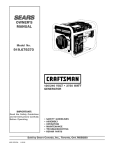
Model
No.
919.670041
i,,CRRFTSMRNI
120/240
VOLT • 4250
WATT
GENERATOR
• SAFETY
GUIDELINES
• ASSEMBLY
IMPORTANT:
• OPERATION
Read the Safety Guidelines
and All Instructions
Care-
• MAINTENANCE
fully Before
• TROUBLESHOOTING
Operating
Sold
MGP-670041
Rev. 0
1/11/00
by Sears
• REPAIR
PARTS
Canada,
Inc.,
Toronto,
Ont.
M5B2B8
Warranty
...................................................
Safety Guidelines
..................................
Assembly
.............................................
Operation
..........................................
Maintenance
Service
2
3-8
...................................................
Troubleshooting
9-10
.....................................
Adjustments
Storage
Generator
Guide ..........................
Parts ................................
11-15
Engine Parts .....................................
16-18
How To Order Parts .................
.............................
19
19
20-26
27-36
Back Cover
18
GHORSEPOWER
DATE PURCHASED:
MODEL NO:
9 HP
l
ASOLINE CAPACITY
7 GALLON/26.5 LITERS
IL CAPACITY
37.1OZ./1.1
L TERS
SERIAL NO:
MAINTENANCE
STORE WHERE PURCHASED:
AGREEMENT
The Sears Warranty, plus a Maintenance Agreement, provide maximum value for your Sears products. Contact
your nearest Sears store for details.
ADDRESS:
CITY:
CUSTOMER
RESPONSIBILITIES
Read and observe the safety rules.
TELEPHONE:
Record the above information
Follow a regular schedule in maintaining, caring for and
using your generator.
about your unit
so that you will be able to provide it incase
loss or theft.
of
Follow the instructions under "Customer Responsibilities" and "Storage" sections of this owner's manual.
FULL ON£ YEAR WARRANTY
ON CRAFTSMAN
GENERATORS
For one year from the date of purchase, when this Craftsman generator is maintained and operated according to the instructions in this owner's manual, Sears will repair, free of charge, any defect in material and workmanship.
If your Craftsman Generator is used for commercial
date of purchase.
or rental purposes, this warranty applies for only 90 days from the original
FULL ONE YEAR WARRANTY ON CRAFTSMAN
ENGINE
For one year from the date of purchase, when this Craftsman engine is maintained and operated according to the instructions
in this owner's manual, Sears will repair, free of charge, any defect in material and workmanship.
If your Craftsman engine is used for commercial or rental purposes, this warranty applies only for 90 days from thedate
of
purchase. This warranty does not cover: Expendable items such as spark plugs and air filters, which become worn during
normal use.
Repairs necessary because of operator abuse or negligence, including damage resulting from no oil being supplied to
the engine or failure to maintain the equipment according to the instructions contained in this owner's manual, are not
covered under warranty.
WARRANTY SERVICE IS AVAILABLE BY RETURNING THE GENERATOR TO THE NEAREST SEARS SERVICE CENTER. This
warranty gives you specific legal rights and you may also have other rights, which vary from PROVINCE TO PROVINCE.
Sold by Sears Canada, Inc., Toronto, Ont.
MGP*670041
2 -- ENG
This manual contains information that is important for you to know and understand. This information relates to
protecting YOUR SAFETY and PREVENTING EQUIPMENT PROBLEMS. To help you recognize this information,
we use the symbols to the right. Please read the manual and pay attention to these sections.
DANGER indicates an imminently hazardous situation
which, if not avoided, wirl result in death or serious
CAUTION indicates a potentially hazardous situation
which, if not avoided, _
result in minor or moderate
in_juE,
iniuw.
WARNING indicates a potentially hazardous situation
which, if not avoided, could result in death of serious
inEig__.
CAUTION used without the safety alert symbol indicates a
potentially hazardous situation which, if not avoided,
result in property damaqe.
This product is not equipped with a spark arresting muffler. If the product will be used around flammable
materials, or on land covered with materials such as agricultural crops, forest, brush, grass, or other similar items,
then an approved spark attester must be installed and may be legally required in other countries.
• SAVE THESE
INSTRUCTIONS
When using this product basic precautions
followed including the following:
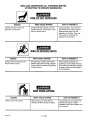
RISK
OF ELECTROCUTION
"
should always be
AND
FIRE
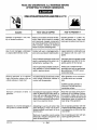
HAZARD
WHAT COULD HAPPEN
HOW TO PREVENT IT
Attempting to connect generator directly to the electrical system of any
building structure.
Back feeding electricity through a
building's electrical system to the
outside utility feed )ines cou)d endanger repair persons attempting to
restore service.
Never backfeed electricity througt
a structure's electrical system.
To connect to a structure's electri
cat system in a safe manner,
always have a Double-Throw
Transfer Switch installed by a
qualified electrician and in compli
Restoration of electrical service while
ance with local ordinances. (Whel
the generator is connected to the
installing a Double-Throw
incoming utility could result in a fire or I Transfer Switch, a minimum of
serious damage if a isolator switch is
10 gauge wiring must be used.)
not installed.
Attempting to connect to the incoming utility service could result in
electrocution.
Failure to use a double throw transfer
switch when connecting to a structures electrical system can damage
appliances and WILL VOID the
manufacturers warranty.
3 -- ENG
MGP-670041
READ AND UNDERSTAND
ALL WARNINGS
BEFORE
ATTEMPTING
TO OPERATE GENERATOR.
RISK
OF ELECTROCUTION
AND
F!RE (cont'd)
HOW TO PREVENT
IT
HAZARD
WHAT COULD HAPPEN
Operation of generator in rain, wet,
icy, or flooded conditions.
Water is an excellent conductor of electricity! Water which comes in contact
with electrically charged components
can transmit electricity to the frame and
other surfaces, resulting in electrical
shock to anyone contacting them.
Operate generator in a clean, dry,
well ventilated area. Make sure
Contact with worn or damaged extension cords could result in electrocution,
Inspect extension cords before use
and replace with new cord if required.
Use of undersize extension cords could
result in overheating of the wires or attached items, resulting in fire.
Use proper size (wire gauge) cordset
for application see chart in the Assembly section of this manual.
Use of ungrounded cordsets could prevent operation of circuit breakers and
result in electrical shock.
Always use a cordset having a
grounding wire with an appropriate
grounding plug. DO NOT use an
ungrounded plug.
Accidental leakage of electrical current
could charge conductive surfaces in
contact with the generator.
Place generator on low conductivity surface such as a concrete
slab.
Use of worn damaged, undersized
or ungrounded extension cords.
Placing generator on or against
highly conductive surface, such as
a steel walkway or metal roof.
hands are dry before touching unit.
ALWAYS operate generator a
minimum of six feet from any
conductive surface.
Improper connection
generator.
to
Exceeding the load capacity of the generator by attaching too many items, or
items with very high load ratings to it
could result in overheating of some
items or their attachment wiring resulting in fire or electrical shock.
Read the load rating chart and instructions in the Wattage Calculation section. Make sure that the
summation of electrical loads for all
attachments does not exceed the
load rating of the generator.
Operation of unit when damaged, or
with guards or panels removed.
Attempting to use the unit when it has
been damaged, or when it is not functioning normally could result in fire or
electrocution.
Do not operate generator with mechanical or electrical problem, Have
unit repaired by an Authorized Service Center.
Removal of guarding could expose
electrically charged components and
result in electrocution.
Do not operate gene:'ator with protective guarding removed.
MGP-670041
of items
4 -- ENG
READ AND UNDERSTAND
ALL WARNINGS
BEFORE
ATTEMPTING
TO OPERATE GENERATOR.
RISK OF FIRE
HAZARD
WHAT COULD HAPPEN
Attempting to fill the fuel tank while
the engine is running.
Gasoline and gasoline vapors can
become ignited by coming in contact
with hot components such as the
muffler, engine exhaust gases, or from
an electrical spark,
Turn engine off and allow it to cool
before adding fuel to the tank.
Equip area of operation with a fire
extinguisher certified to handle
gasoline or fuel fires.
Sparks, fire, hot objects
Cigarettes, sparks, fires, or other hot
objects can cause gasoline or gasoline vapors to ignite.
Add fuel to tank in well ventilated
area. Make sure there are no
sources of ignition near the
generator.
Improper storage of fuel
Improperly stored fuel could lead to
accidental ignition. Fuel improperly
secured could get into the hands of
children or other unqualified persons.
Store fuel in a OSHA approved
container designed to hold gasoline. Store container in secure
Materials placed against or near the
generator or operating the generator
_nareas where the temperature
exceeds 104 ° F. ambient (such as
storage rooms or garages) can
interfere with its proper ventilation
features causing overheating and
-possible ignition of the materials or
Operate generator in a clean, dry,
well ventilated area a minimum of
Inadequate ventilation for generator
Tampering with factory set engine
speed settings.
Overfilling the fuel tank fuel spillage.
buildings.
Engine speed has been factory set to
:)rovide safe operation. Tampering
with the engine speed adjustment
could result in overheating of attachments and could cause a fire.
Spilled fuer and its vapors can become ignited from hot surfaces or
sparks.
HOW TO PREVENT
location to prevent use by others.
four feet from any building, object
or wall. DO NOT OPERATE UNIT
INDOORS OR IN ANY CONFINED AREA.
Never attempt to "speed-up" the
engine to obtain more performance. Both the output voltage
and frequency will be thrown out
of standard by this practice,
endangering attachments and the
user.
Use care in filling the tank to avoid
spilling fuel Make sure fuel cap is
secured tightly and check engine
for fuel leaks before starting
engine. Move generator away
from refueling area or any spillage
before starting engine. Allow for
fuel expansion. Keep maximum
fuel level ¼ inch below the tip of
the fuel tank. Never refuel with the
engine running.
5 -- ENG
IT
READ AND UNDERSTAND
ALL WARNINGS
Risk of Injury and Property Damage
Transportina
Generator
HAZARD
WHAT COULD
Fire, Inhalation, Damage to Vehicle
Surfaces
HAPPEN
Fuel or oil can leak or spill and could
result in fire or breathing hazard,
serious injury or death can result. Fuel
or oil leaks will damage carpet, paint
or other surfaces in vehicles or
trailers.
BEFORE
When
HOW TO PREVENT IT
If generator is equipped with a fuel
shut-off valve, turn the valve to the
off position before transporting to
avoid fuel leaks. If generator is not
equipped with a fuel shut-off valve,
drain the fuel from tank before
transporting. Transport fuel only in
an OSHA approved container.
Always place generator on a
protective mat when transporting
to protect against damage to
vehicle from leaks. Remove
generator from vehicle immediately upon arrival at your destination
RISK OF BREATHING
HAZARD
Gasoline engines produce toxic
carbon monoxide exhaust fumes.
MGP-670041
- INHALATION
WHAT COULD HAPPEN
Breathing exhaust fumes will cause
serious injury or death.
6 -- ENG
HAZARD
HOW TO PREVENT IT
Operate generator in clean, dry,
well ventilated area. Never
operate unit in enclosed areas
such as garages, basements,
storage, sheds, or in any location
occupied by humans or animals.
Keep children, pets and others
away from area of operating unit.
READ
AND UNDERSTAND
ALL WARNINGS
BEFORE
ATTEMPTING
TO OPERATE GENERATOR.
RISK OF UNSAFE
HAZARD
Operation
manner.
of generator
OPERATION
WHAT COULD HAPPEN
in careless
All sources of energy include the
)otential for injury. Unsafe operation
or maintenance of your generator
could lead to serious injury or death
to you or others.
HOW TO PREVENT
•
•
•
•
IT
Review and understand all of
the operating instructions and
warnings in this manual.
Become familiar with the
operation and controls of the
generator. Know how to shut it
off quickly.
Equip area of operation with a
fire extinguisher certified to
handle gasoline or fuel fires.
Keep children or others away
from the generator at all times.
Operation of voltage sensitive appliances without a voltage surge protector.
Any gasoline operated household
generator will incur voltage variations
causing damage to voltage sensitive
appliances or could result in fire.
Always use a U.L. listed voltage
sensitive surge protector to
connect voltage sensitive appliances such as TV, computer, or
stereo equipment. Failure to use
a U.L. listed voltage surge
protector will void the warranty
on your generator.
Notice: A multiple outlet strip is
not a surge protector make sure
you use a U.L. listed voltage surge
)rotector.
Raising or suspending generators
equipped with lift rings improperly
Generator could fall causing serious injury or death to you or others.
Always use proper connecting
)rocedures as described in this
Improper raising or suspending can
cause damage to the generator.
manual when connecting cables,
chains, or straps for raising or
suspending generators equipped
with lift rings.
Always use cables, chains, or
straps rated at 2000 Ibs working
load or more to raise or suspend
generator.
Operating generator while suspended
Generator will not operate properly
and will cause damage to the generator and could cause serious injury or
death to you or others.
7 -- ENG
Never operate generator while
suspended or in an unlevel position. Always operate generate on
a flat, level surface.
MGP-670041
READ AND UNDERSTAND
ALL WARNINGS
BEFORE
ATTEMPTING
TO OPERATE GENERATOR.
RISK OF HOT SURFACES
HAZARD
Contact with hot engine and
generator components.
WHAT COULD HAPPEN
HOW TO PREVENT IT
Contact with hot surfaces, such as
engines exhaust components, could
result in serious burns.
During operation, touch only the
control surfaces of the generator.
Keep children away from the
generator at all times. They may
not be able to recognize the
hazards of this product.
RISK OF MOVING
HAZARD
Contact with moving parts can
result in serious injury.
WHAT COULD
HAPPEN
The generator contains parts which
t_otateat high speed during operation.
These parts are covered by guarding
to prevent injury.
RISK FROM
HAZARD
Lifting a very heavy object.
MGP-670041
PARTS
HOW TO PREVENTIT
Never operate generator with
guarding or cover plates removed.
Avoid wearing loose fitting clothing
or jewelry which could be caught
by moving parts.
LIFTING
WHAT COULD HAPPEN
Serious injury can result from attempting to lift too heavy an object.
8 -- ENG
HOW TO PREVENT
IT
The generator is too heavy to be
lifted by one person. Obtain
assistance from others before you
try to move it.
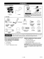
CARTON
- Parts Bag
CONTENTS
"1 - Twlstlock
1 - Owner's
Plug L5-2OP
Manual
"1 - Twlstlock
Plug L14-20P
To be installed and/or used in
1 - Handle
1 - Generator
1 - Parts
accordance with appropriate local electrical codes
and regulations. Refer to enclosed instructions for
proper installation.
Box
_2
- Wheels
_l-Foot
Bracket
1 - Isolator
Foot
7 - 5/16-18
x 3/4"
9 - 5/16-18
Lock Nuts
Cap Screws
(6 used)
2 - Bracket
2 - Shoulder
Bolts
©
2 - Handle
2 - 5/16-18
x 1 3/4
Cap Screws
"
2 - Washers
2 - 318-16
Lock Nuts
Caps
Read owner's manual. Do not attempt to operate equipment until you have read Owner's
Manual for Safety, Assembly, Operation, Maintenance, Storage Instructions.
NOTE: Left and right describes the location of a part
with the operator facing the outlet panel,
TOOLS
NEEDED
FOR ASSEMBLY
1- Box Cutter or Knife
REMOVE
GENERATOR
FROM
CARTON
*
Open carton from top.
•
Cut carton along dotted lines.
•
Remove all carton inserts.
•
Remove generator through opening in carton.
2 - 1/2" Wrenches
2 - 9/16" Wrenches
1 - 1" thick x 1' square piece of wood
IMPORTANT: Before any attempt to start your generator be sure to check engine oil (See Adding Engine Oil
paragraph in the Operation section on page 13 of this
manual.)
9 -- ENG
MGP-670041
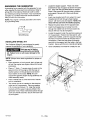
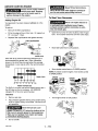
GROUNDING
Locate the engine support. Place one wheel
bracket (4) on top of support as shown in illustration. Align with the pre-drilted holes in support.
Place 2 cap screws (9) through holes in bracket
and support. Secure with 2 lock nuts (8) and
tighten.
THE GENERATOR
A grounding lug is supplied with the generator for use
when required by local electrical ordinances. Refer to
article 250 of the National Electrical Code to clarify
any needed grounding information. Your local electric
company or a certified electrician should be able to
help you with this information.
Insert one shoulder bolt (2) into wheel (1). Insert
threaded end of bolt through wheel bracket,
secure with lock nut (3) and tighten. NOTE: The
wheel will not rub frame if installed properly.
NOTE: Your engine is already grounded to the frame
by a grounding strap.
Repeat the above steps for the opposite side.
Insert the threaded stud of rubber foot (10)
through the middle hole of the foot bracket (5).
Secure with lock nut (8) and tighten.
Grounding
INSTALLING
WHEEL
Locate the support under the electrical outlet end
of the generator. Position foot bracket (5), with
rubber foot installed, under the support and align
the holes in the foot bracket (5) with the slots in
the support. Place one cap screw (9) through
each slot in the support and the holes in the foot
bracket. Secure with the lock nuts (8) and tighten.
Lug
KIT
The Craftsman Wheel Kit was designed to greatly
improve the portability of your generator.
Once completed,
the wheel kit is ready for use.
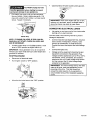
Drain gas and oil before
assembling the port;ability
kit. Failure to do so will cause damage to the
engine.
NOTE: Always follow state regulations for proper oil
disposal.
•
•
•
•
Place generator on level ground; qrain all gas and
oil from the engine (see engine manual for correct
procedure).
11
12
Place a 1" thick x 1' square piece of wood on the
ground in front of the engine. With the help of
another person, tilt the generator and rest the
recoil starter on the wood. NOTE: This wil!
support the gasoline engine during assembly and
make assembly easier.
Place a handle cap (7) onto each end of handle
prior to installation.
The handle should be installed on the electrical
outlet end of the generator. Place one washer
(12) on long cap screws (11). Align the handle
brackets with the upper holes pre-drilled in the
generator frame. Place mentioned screws through
frame and handle brackets. Secure with lock nuts
(8) and tighten.
MGP-670041
10-
2
8
10
ENG
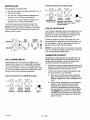
KNOW YOUR
I
GENERATOR
tion with your generator to familiarize yourself with the location of various controls and adjustments. Save the
manual
for Owner's
future references.
Read this
Manual and Safety Rules before operation of your Generator, Compare this illustra-
MUFFLER
ENGINE ON/OFF
SWITCH
(not shown)
SPARK PLUG_
FOUR
CIRCUIT
FUEL TANK
AIR CLEANER "
BREAKERS FUEL CAP
\
FUEL VALVE
LEVER
CHOKE
CONTROL
120 VOLT
DUPLEX
-RECEPTACLE
FUEL SHUT OFF VALVE
(not shown)
120 VOLT 3-PRONG
TWISTLOCK
RECEPTACLE
FILL
240 VOLT4-PRONG
TWlSTLOCK
RECEPTACLE
ENGINE OIL DRAIN
FULL POWER
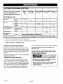
SWITCH
FUEL TANK- Capacity of 7 US gallons/26.5
CHOKE CONTROL-
Liters.
CIRCUIT BREAKER- Each receptacle has a circuit
breaker to protect the generator from overloading.
Used to start cold engine.
120 VOLT RECEPTACLES- Used to supply 4250
watts of electrical power per receptacles when the
Full Power Switch is in the 120V position and 2125
watts with the Full Power Switch in the 120/240V
ENGINE ON/OFF SWITCH- Sets engine in starting
mode for recoil starter - Stops running engine.
FUEL VALVE LEVER (located on engine) - Used to
shut off the flow of fuel to the engine.
position.
FUEL SHUT OFF VALVE (located under gas tank) Used to shut off the flow of fuel to the engine.
ENGINE OIL FILL- Check and fill engine with oil.
AIR CLEANER- Includes filter element cartridge and
foam pre-cleaner that limits the amount of dirt that
enters the engine.
Protected by 15 amp circuit breaker.
240 VOLT TWlSTLOCK
RECEPTACLE - Used to
supply 4250 watts of electrical power per receptacles
when the Full Power Switch is in the 120V position
and 4250 watts with the Full Power Switch is in the
120/240V position. Protected by 15 amp circuit
breaker.
FULL POWP2R SWITCH - Allows the operator to distribute power across the outlets.
11 -- ENG
MGP-67CO41
Full Power Switch in the 12OV position
RECEPTACLES
Your generator is equipped with:
•
one 120 volt duplex receptacle
amp circuit breaker
•
one 120 volt 3-prong twistlock receptacle protected by a two 15 amp circuit breakers
•
0@@0
120V 15A
protected by a 15
one 240 volt 4-prong twistlock receptacle
tected by two 15 amp circuit breakers
®
NEMA 5-20R
Duplex
4250 Watts Surge
2125 continuos
pro-
The circuit breakers are provided to protect the
generator against electrical overload. If the circuit
breaker trips, unplug electrical load from receptacle.
Let circuit breaker cool clown and then push circuit
breaker button to reset.
SWITCH
When placed in the 120V position it allows you to
receive the full capacity of the generator by using all
120 volt receptacles. When in the 120/240 position,
you will only be able to receive 2125 watts when using
the 120 volt receptacles and the full 4250 watts when
using the 240 4-prong twistlock receptacle.
Duplex
2125 Watts
MGP*670041
3-prong
Twistlock
2125 Watts
.
®
CAPACITY
•
There are two types of electrical appliances that
can be powered by your generator:
A.
r-i
120V
4250 Watts surge together
2125 Watts continuous together
No 240V available
Starting and running wattage requirements should
always be calculated when matching a generators
wattage capacity to the appliance or tool.
12OV 24OV 15A
4-prong
Twistlock
4250 Watts
12(_240V
•
B,
NEMA LS-2OR
12OV
Exceeding the rated capacity of your generator can
result in serious damage to your generator and connected electrical devices. You should observe the
following to prevent overloading the unit:
®
5-20R
4-prong
Twistlock
NOTE: The Low Oil Shutdown mechanism is very sensitive. You must fill the engine to the full mark on the dipstick to inactivate this safety device.
Full Power Switch in the 120V/240V position
NEMA
3-prong
Twistlock
If while the engine is running, the oil gets low, it will
automatically shut itself down and will not restart until
the oil is added. If the oil is low before start-up, the
generator will not start until oil is added.
GENERATOR
15A
. ®
Your Craftsman generator engine is equipped with Low
Oil Shutdown. Low Oil Shutdown is a safety device
designed to protect your engine from damage in the
event the oil level in the crankcase is low.
®
120V
tSA
LOW OIL SHUTDOWN
®
FULL POWER
12OV 240V
120/240V
12 -- ENG
Items such as radios, light bulbs, television
sets, and microwaves have a "resistive load".
Starting wattage and running wattage are the
same.
Items such as refrigerators, air compressors,
washer, dryer, and hand tools that use an
electrical motor have an "inductive load".
Inductive load appliances and tools require
approximately 2 to 4 times the listed wattage
for starting the equipment. This initial load
only lasts for a few seconds on start-up but is
very important when figuring your total wattage to be used.
NOTE: Some inductive appliances and tools will list
on the motor name plate, the starting and running
voltage and amperage requirements. Use the following
formula to convert voltage and amperage to wattage:
(Volts X Amp = Watts)
•
NOTE: On 120-volt loads the maximum starting wattage should NOT exceed one half of the rated generator
wattage. Example: a 4250 rated wattage generator =
2125 maximum starting wattage.
FROM
There are basically two ways to obtain electricity from
a generator:
•
Always start your largest electric motor first, and
then plug in other items, one at a time.
The guide is provided to assist you in determining the
appliances and tools that can be ran with the wattage
capacity of your generator.
OBTAINING ELECTRICITY
GENERATOR
Use of extension cords directly from the generator to the appliance, lights, tools, etc.
Use of a double-throw transfer switch installed
•
directly to the main electrical supply outside of
the house.
Extension
Cord
When using an appliance or tool at a considerable
distance from the generator, a 3-wire extension cord
that has a 3-blade grounding plug and a 3-slot
receptacle that accepts the tool's plug MUST be
used in order to reduce the risk of electrical shock. A
cord of adequate size must be used. A minimum of 12
gauge wire size with at least a 20 amp draw can be
used. When amperage exceeds 20 amps a 10 gauge
wire size should be used.
on cord that is hot
touch is overloaded.
Repair or replace damaged extension cords
immediately.
Connecting
Supply
Generator
To Main Electrical
Potential hazards exist when a electrical generator is
connected to the main electrical supply coming into
the house. It is at that point that the generator could
feed back into the utility company's system causing
possible electrocution of workers who are repairing
electrical lines. To avoid back feeding of electricity into
utility systems, a double-throw
transfer switch
should be installed between the generator and utility
power. This device should be installed by a licensed
electrician and in compliance with all local electrical
codes.
NOTE: When installing a Double-ThrowTransfer
Switch, a minimum of 10 gauge wiring must be used.
13 -- ENG
MGP-670041
BEFORE
STARTING
ENGINE
Never fill fuel tank indoors.
_Always
check engine oil level
before every start. Running
engine low of oil or out of oil could result in
Never fill fuel tank when engine is running or
hot. Do not smoke when filling fuel tank.
set ous damage to the engine.
Adding
Engine
Your generator
engine.
To Start
Your Generator
Oil
Never run engine indoors or
has been shipped without oil in the
in enclosed, poor ventilated areas. Engine
exhaust contains carbon monoxide, an odorless and deadly gas.
To add oil:
•
Remove the filler cap/dipstick.
•
Fill to the edge of the oil filler hole. Oil capacity is
37.1 ounces/1.1 liters.
•
Replace filler cap/dipstick
Open the fuel shut-off valve located under the gas
tank. Turn counter clockwise until the valve stops.
and tighten securely.
Filler Cap/Dipstick
Full
Move fuel valve lever to ON position.
Lower Limit
SAE 10W-30 (4 stroke automotive detergent oil) is
recommended for general use. Other viscosities
shown in the chart may be used when the average
temperature in your area is within the recommended
range.
•
II El]!
NOTE: To restart a warm engine, move choke control
to OPEN position.
Upper Limit
-20
I
*30
CHOKE
0
K
-20
I
-10
AMBIENT
I
0
I
t0
I
20
Move choke control lever to CLOSED position.
I
30
CHOKE
OPEN
I
40"C
TEMPERATURE
The SAE oil viscosity and service classifications are in
the API label on the oil container. API SERVICE
category SF or SG oil is recommended.
Gasoline
Remove gas cap.
•
Add unleaded gasoline with a pump octane rating
of 86 or higher, slowly, to fuel tank. Do not mix oil
with gasoline.
Never fill fuel tank completely. Fill tank to 1/2" below the bottom of the
filler neck to provide space for fuel expansion.
Wipe any fuel spillage from engine and equipment before starting engine.
•
Do not overfill.
MGP-670041
14 -- ENG
Turn engine switch to ON position.
I
•
Close fuel shut-off valve located under gas tank.
You MUST unplug any load
from the generator before starting to prevent
permanent damage to any appliances.
Pull starter grip slowly until you feel resistance,
then pull briskly. Return starter grip gently. Pull
rope with a rapid full arm stroke. Let rope rewind
slowly. Repeat if necessary.
IMPORTANT: Never store engine with fuel in tank,
indoors, or in enclosed, poorly ventilated areas or
where fuel fumes may reach an open flame.
CONNECTING
•
Let engine run and warm up for five minutes after
starting with no electrical load.
NOTE: IF ENGINE OIL LEVEL IS TOO LOW, ENGINE WILL NOT START. CHECK OIL LEVEL AND
ADD IF NECESSARY.
Connect inductive load equipment first, inductive
loads consist of refrigerators, freezers, water
pumps, air conditioners, or small hand tools.
Connect the items that require the most wattage
first.
If choke control lever is in CLOSED position, move
lever to OPEN position as engine warms up.
Connect the lights next.
IMPORTANT: Allow generator to run at no load for 5
minutes upon each initial start-up to allow engine and
generator to stabilize.
STOPPING
Voltage sensitive equipment should be the last
equipment connected to the generator. Plug
voltage sensitive appliances such at "IV's, VCR's,
microwaves, ovens, computers, and cordless
telephones into a UL listed voltage sbrge protector, then connect the UL listed voltage surge
protector to the generator.
ENGINE
•
Disconnect
•
Turn engine switch to "OFF" position.
LOADS
Connect loads in the following manner to prevent
damage to equipment:
Starter Grip
•
ELECTRICAL
all electrical loads.
IMPORTANT: You should always add up the rated
watts of all lights, tools and appliances you are
powering at one time. This total should not
exceed the rated capacity of you generator or
circuit breaker rating of the receptacle supplying
power.
Move the fuel valve lever to the "OFF" position.
Fuel
Valve
Lever
15 -- ENG
MGP-67CO4_
CUSTOMER
RESPONSIBILITIES
Perform task at every indicated
month or operating hour
interval, whichever comes first.
MAINTENANCE
TABLE
Before
each
First month or
every 20 Hrs.
Every 3 months
or 50 Hrs.
Every 6 months
or 100 Hrs.
use
TASK
Engine Oil
Check
X
Air Filter
Check
X
X
Change
X
Clean
x (1)
Replace
Sediment
Every year or
300 Hrs.
cup
Check Spark Plug
X
Clean
X
Clean-Readjust
X
Replace
X
Clean
Spark arrester
(optional part)
Fuel line
Check
Prepare Unit for Storage
_
X (2)
Every 2 years (Replace if necessary) (2)
Prepare unit for storage if it is to remain idle for more than 30 days.
1
Service more frequently when used in dusty areas.
2
These items should be service by your authorized service dealer.
Replace the paper air filter element only.
GENERAL
RECOMMENDATIONS
The warranty of the generator does not cover items
that have been subjected to operator abuse or negligence. To receive full value from the warranty, operator must maintain the generator as instructed in this
manual.
enter the cooling air slots and could possibly damage
the rotor, stator and the internal windings of the
generator head.
All adjustments in the Maintenance section of this
manual should be made at least once each season.
ENGINE
Some adjustments will need to be made periodically to
maintain your generator.
GENERATOR
MAINTENANCE
Your generator should be kept clean and dry at all
times. The generator should not be stored or operated in environments that include excessive moisture,
dust or any corrosive vapors. If these substances are
on the generator, clean with a cloth or soft bristle
brush. Do not use a garden hose or anything with
water pressure to clean the generator. Water may
MGP-670041
MAINTENANCE
Improperly maintaining this
engine, or failure to correct a problem before
operation, can cause a malfunction in which
you can be seriously hurt or killed.
Always follow the inspection and maintenance
recommendations and schedules in this
owner's manual.
16 -- ENG
Oil
•
edge of the oil filler hole with the recommended
oil. See the Adding Oil paragraph on page 14 of
this manual.
Oil level should be checked prior to each use and
at least every 5 hours of operation.
Air Filter
To check oil:
•
Remove the filler cap/dipstick
and wipe it clean.
•
Insert and remove the dipstick without screwing it
into the filler neck. Check the oil level shown on
the dipstick,
•
•
If the oil level is tow, fill to the edge of the oil filler
hole with the recommended oil. See the Adding
Oil paragraph on page 14 of this manual.
•
Screw in the filler cap/dipstick
A dirty air filter will restrict air flow to the carburetor,
reducing engine performance. If you operate the
engine in very dusty areas, clean the air filter more
often than specified in the Owner's Responsibilities
Remove the wing nut from the air cleaner cover,
and remove the cover.
Air Cleaner Cover,
securely.
ap/Dipstick
Upper Limit
o
Paper Filter
O
Foam
Filter
Element
Element
Changing
_
Engine Oil
For a new engine, change oil after the first 20 operating hours. Thereafter, change oil after every 100
hours of operation.
Gasket
Change the oil while the engine is still warm. The oil
will flow freely and carry away more impurities. Make
sure the engine is level when filling, checking or
changing oil.
Change the oil as follows:
•
To keep dirt, grass clippings, etc. out of the
engine, clean the area around the drain plug and
dipstickbefore removing it.
•
•
Remove the wing nut from the air filter and remove
the filter.
Remove the foam filter from the paper fitter.
Inspect both air filter elements and replace them if
the are damaged. Always replace the paper air
filter element at the scheduled interval. See
Customer's Responsibilities on page 16 of this
manual
Place a suitable container below the engine to
catch the used oil, then remove the filler cap/
dipstick and the drain plug.
_
IJ
\
_._-_4_
Clean the air filter elements if they are to be
reused.
/
./"
Filler Cap/
To clean the paper element:
oipst,ck
•
o.
Dr&in_" Level
Plug
Allow the used oil to drain completely, then
reinstall the drain plug, and tighten it securely.
To
Please dispose of used motor oil in a manner that
is compatible with the environment. We suggest
you take used oil in a sealed container to your
local recycling center or service station fro reclamation. Do not throw it in the trash, pour it on the
ground, or down a drain.
Tap the filter element several times on a hard
surface to remove dirt, or blow compressed
air (not exceeding 30 psi, 207kPa, 2.1 kg/cm 2)
through the filter element from the inside.
Never try to brush off dirt; brushing with force
dirt into the fibers.
clean the foam air filter element:
Clean in warm in warm soapy water, rinse, and
allow to dry thoroughly. Or clean in nonflammable solvent and allow to dry. Dip the filter
element in clean engine oil, then squeeze out
all excess oil. The engine will smoke when
started if too much oil is left in the foam.
With the engine in a level position, fill to the outer
17 -- ENG
MGP-670041
•
Wipe dirt from the inside of the air cleaner base
and cover, using a moist rag. Be careful to
prevent dirt from entering the air duct that leads
to the carburetor.
•
Place the foam air filter element over the paper
element, and reinstall the assembled air filter. Be
sure the gasket is in place beneath the air filter.
Tighten the air filter wing nut securely.
•
--
)
O':_nnumg;
nt
Install the air cleaner cover, and tighten the cover
wing nut securely.
Sediment
•
Cup Cleaning
Move the fuel valve lever to the "OFF" position,
then remove the fuel sediment cup and O-Ring.
Fuel Valve
Lever
•
Wash the sediment up and O-Ring in nonflammable solvent, and dry them thoroughly.
•
Place the O-ring in the fuel valve, and install the
sediment cup. Tighten the sediment cup securely.
•
Move the fuel valve to the "ON" position and
check for leaks. Replace the O-ring if there is any
leakage.
Clean
and Replace
Spark
Plug
Check spark plug yearly or every t00 operating hours.
OFF
Gasoline is highly flammable and explosive.
You can be burned or seriously injured when
handling fuel.
•
Keep heat, sparks, and flame away.
•
Handle fuel only outdoors.
•
Wipe up spills immediately.
•
Clean area around spark plug.
•
Remove and inspect spark plug.
•
Replac e spark plug if electrodes
or porcelain is cracked.
•
Check electrode gap with wire feeler gauge and
set gap .030 if necessary.
•
Install spark, tighten securely.
are pitted, burned
.030" (0.76MM)
o
Spark Plug
CARBURETOR
The carburetor of your generator is pre-set at the factory. The carburetor should net be tampered with. If your
generator is used at an altitude in excess of 4000 feet
performance may be affected. If so consult with your
nearest Sears Service Center regarding high altitude set
changes.
GOVERNOR
Your engine governor maintains the constant operating
speed of your generator. DO NOT tamper with the engine governor which is factory set for proper engine
speed.
MGP-67004_
Over-speeding your engine above factory high speed setting can be dangerous and could possibly cause personal injury or property damage. If you believe the engine is running too fast or slow, take your generator to a
Authorized Sears Service Center for repair and adjustment.
I
Low engine speeds impose a I
heavy load on the engine and
when sufficient power is not available the engine
18 -- ENG
fe cou d be shortened.
If you are going to store your generator for more than
30 days, use the following information as a guide to
prepare the generator for storage.
Never store generator with
in the tank indoors or in
•
Disconnect the spark plug wire and remove the
spark plug.
•
Add one teaspoon of oil through the spark plug
hole.
•
Place rag over spark plug hole and pull the recoil a
few times to lubricate the combustion chamber.
Replace the spark plug, but do not connect the
spark plug wire.
enclosed, poorly ventilated areas, where fumes
can reach an open flame, spark or pilot light as
on a furnace, water heater, clothes dryer or
other gas appliances.
Engine Preparation
NOTE: If a fuel stabilizer is not used, all gasoline must
be drained from the tank and carburetor to prevent gum
deposits from forming on these parts and causing possible malfunction of the engine.
•
Add fuel stabilizer to fuel tank to minimize the
formation of fuel gum deposits during storage.
Generator
•
Run engine at least 10 minutes after adding
stabilizer to allow it to enter the fuel system.
PROBLEM
Engine will not start
Clean the generator as outlined in the Generator
Maintenance paragraph on page 16.
Check that cooling air slots and openings on
generator are open and unobstructed.
CORREC_ON
CAUSE
1.
Low on fuel or oil
1. Add fuel or oil.
2.
Ignition switch in "Off" position.
2. Turn to "ON" position
3.
Faulty spark plug.
3. Replace spark plug.
4.
Choke in wrong position.
4. Adjust choke accordingly.
5.
Fuel shut-off valve in closed
5. Open fuel shut-off valve.
position.
No electrical output
6.
Unit loaded during start-up.
6.
Remove load from unit.
7.
Spark plug wire loose.
7. Attach wire to spark plug.
1.
Faulty receptacle.
1.
Have Authorized Sears Service
Center replace.
Repeated
ping
circuit breaker trip-
Generator overheating the
circuit breaker depressed
2.
Depress and reset.
3.
Have Authorized Sears Service
Center replace capacitor.
Faulty power cord.
4.
Repair or replace cord.
1.
Overload
2.
Faulty cords or equipment.
1. Reduce load.
2. Check for damaged, bare, or
frayed wires on equipment.
Replace.
1.
2.
Generator overloaded.
Insufficient ventilation.
2.
Circuit breaker kicked out.
3.
Defective capacitor.
4.
19 -- ENG
1. Reduce toad.
2. Move to adequate supply of
fresh air.
MGP-610041
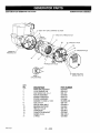
CRAFTSMAN
4250
GENERATOR
919.670040
GENERATOR
4
12
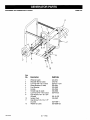
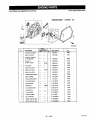
TORQUE
KEY
NO,
1
2
3
4
5
6
7
8
9
10
11
12
13
14
15
16
17
18
19
20
96-120 IN-LBS
DESCRIPTION
FUEL TANK
FUEL TANK SCREWS
WASHER
FUEL CAP
FRAME ASSEMBLY
PANEL ASSEMBLY
ISOLATOR
FUEL HOSE
HEAT SHIELD
ISOLATOR
LOCK NUT 5/16-18
SCREW 5/16-18 x 1
LOCK WASHER
SCREW 5/16-18 x 3/4
GROUND STRAP
ENGINE (model # GX270VWN2)
HOSE CLAMP .301 ID
UNION REDUCER 1/4 TO 3/8
SCREW 1/4 x 5/8
LOCK WASHER
* SEE ENGINE PAGES 27-36
MGP-670041
20 -- ENG
PART NUMBER
GS-0795
91895680
SSN-632
GS-0443
GS-0909
GS-0844
GS-0433
GS-0225
GS-0675
GS-0033
SSF-8150
SSF-605
SSN-1619-ZN
SS-12-CD
GS-0118
GS-0560
GS-0535
39124607
SS-1503-CD
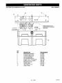
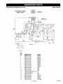
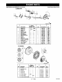
ASSEMBLY
CRAFTSMAN
4250
GENERATOR
919.670040
GENERATOR
ASSEMBLY
33
21
32 TORQUE
25-30
IN-LBS
31
• 28
24 _
26 TORQUE
25
45-55 IN-LBS
22
KEY
NO.
21
22
23
24
25
26
27
28
29
3O
31
32
33
DESCRIPTION
LABEL, OPERATION
SCREW, HEX WASHER
FUEL CLAMP .50 ID
FUEL FILTER
GROUND LUG
SCREW 10-24 x 9/16
END COVER
ENGINE COVER
FUEL SHUT OFF VALVE
DRAINCOCK GROMMET
LOCK WASHER #10
SCREW M5 x 12HHCS
LABEL, WARNING
21 -- ENG
PART NUMBER
LA-3048-1
SSF-928
GS-0227
GS-0459
GS-0117
SSF-553-1
GS-0077
GS-0540
GS-0437
GS-0446
SSN-626
SSF-627
LA-2911
MGP-670041
CRAFTSMAN
4250
GENERATOR
919.670040
GENERATOR
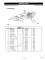
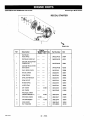
ORIENT
WITH
VENTS
DOWNWARD
HEAD ASSEMBLY
AS SHOWN
2
3
5
TORQUE
UNTILTHREADS
RUN OUT
9
10
1 2
TORQUE
E0-70 IN-LSS
TORQUE30-401N-LBS
SHOWN
REFERENCE
FOR
ONLY
8 TORQUE
SCALE
CAPACITOR
KEY
NO.
1
2
3
4
5
6
7
8
9
10
12
13
16
17
21
MGP-E70041
120-144
IN-LES
21 INSERTINTOO-RING
GROOVE,PARTOF 10
1:1
WIRING
DESCRIPTION
DRIVE END ADAPTER
LOCK WASHER 3/8
CAP SCREW 3/8-16 x 1
ROTOR ASSEMBLY
STATOR THRU BOLT
STATOR ASSEMBLY
WASHER 11/16OD x 11/32
NUT 5/16-24
ROTOR THRU BOLT
BEARING SUPPORT
HEX NUT 1/4-20
CAPACITOR
CAPACITOR BRACKET
SCREW 10-24
O-RING
22 -- ENG
PART NUMBER
GS-0076
SSN-619
SSF-577
GS-0883
GS-0110
GS-0884
SS-6506-CD
SSF-576
GS-0091-1
GS-0861
SSF-575
GS-0873
GS-0595
SSF-553-1
GS-0862
CRAFTSMAN
4250
GENERATOR
919.670040
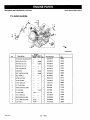
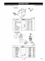
PANEL ASSEMBLY
10
6
11
I
I_ 3
__.......
: .........
/
:7o:::°j:"-_vIc_s
TO F_E
COVER/
_]_//
SNAPPED INTO OPENING
5
INSIDE
REAR
_TE
--
I
b_
KEY
NO_
1
2
3
4
5
6
7
8
9
10
11
DESCRIPTION
RECEPTACLE, DUPLEX
3 PRONG TWISTLOCK
4 PRONG TWlSTLOCK
CIRCUIT BREAKER
FULL POWER SWITCH
SCREW, 10-9 X .50 PLASTITE
SCREW, #6-32 X .50 TORX
SPEED NUT, #6-32
COVER, PANEL
HEX JAM NUT 7/16
LABEL, PANEL
23 -- ENG
PART NUMBER
GS-0804
GS-0480
GS-0445
GS-0024
GS-0045
SSF-3156
SSF-583
SSF-584
GS-0017-1
SSF-595
LA-3388
MGP-670041
CRAFTSMAN
4250
GENERATOR
919.670040
WHEEL
6
11
12
8
2
8(_
8
10
Key
No..__, DescriPtion
1
2
3
4
5
6
7
8
9
10
11
12
MGP*670041
PART NO.
Wheel (2 used)
Shoulder Bolt (2 used)
Lock Nut 3/8"-16 (2 used)
Wheel Bracket (2 used)
Foot Bracket
Handle
Handle Cap (2 used)
Lock Nut 5/16"-18 (9 used)
Cap Screw 5/16"-18 x 3/4"
(6 used)
Isolator Foot
Cap Screw 5/16-18 x 1.75"
(2 used)
Washer (2 used)
24 -- ENG
AC-0014
CAC-60
SSF-8111-ZN
GS-0561
GS-0562
GS-0564
GS-0565
SSF-8150
SS-12-CD
GS-0587
SSF-999-1
SS-6506-CD
KIT
CRAFTSMAN 4250 GENERATOR 919.670040
WIRING
CONTROL
PANEL
REAR VIEW
DIAGRAM
REAR VIEW
HOUSING
(MALE)
REAR VIEW
HOUSING
(FEMALE)
SEE VIEW "A"
KEY
NO.
1
DESCRIPTION
WIRE #12 AWG
COLOR
GREEN
2
3
WIRE
WIRE
WIRE
WIRE
#12
#12
#12
#12
AWG
AWG
AWG
AWG
GREEN
GREEN
GREEN
GREEN
9
10
WIRE
WIRE
WIRE
WIRE
WIRE
#12
#12
#12
#12
#12
AWG
AWG
AWG
AWG
AWG
GREEN
GREEN
GREEN
GREEN
RED
11
12
13
14
WIRE #12 AWG
WIRE #12 AWG
TUBE HEAT SHRINK 1.5 IN
SPLICE TERMINAL
RED
RED
NA
NA
15
16
17
18
19
WIRE
WIRE
WIRE
WIRE
WIRE
RED
BLACK
BLACK
BLACK
ORANGE
4
5
6
7
8
#12
#12
#12
#12
#12
AWG
AWG
AWG
AWG
AWG
25 -- ENG
MGP-670041
CRAFTSMAN
4250
GENERATOR
919.670040
WIRE HARNESS
16+/- 50 IN. LONG
NOTE:
(_
TAPE CONDUIT WITH 3/4 • WIDE BLACK ELECTRICAL TAPE
REAR
W_IONR G STATOR
VIEW
LEADS (I,2,3,4)
LEADSTOSTATOR
AUX.
WINDING
I
50uF CAPACITOR
OUSING
{MALE)
,°,
!
KEY
MGP-670041
(_
GROUND TOIF'RAME
N__Q.
1
2
3
DESCRIPTION
WIRE PIN/MALE
WIRE PIN/MALE
WIRE PIN/MALE
4
5
6
7
WIRE PIN/MALE
PLUG FRONT
PLUG REAR
CONDUIT FLEXIBLE
26 -- ENG
R_AR
HOUSING
VIEW
(FEMALE)
CRAFTSMAN
4250
GENERATOR
CYLINDER
919,670040
Honda
Engine
Model
GX270
HEAD
17
5
13
15
15
13
16
9
14
11
?
1o
ZH98E0200
Ref
1
Description
CYLINDER
HEAD
COMP
2
Engine
Serial Number
From
To
Qty
!
Part Number
12200-ZH9-000
HIC
4475349
GUIDE,
VALVE
(OS)
(1)
12..204-ZE2-306
4179164
3
GUIDE,
EXVALVE(OS)
(1)
12205-ZE2-305
2089563
4
CLIP,
VALVE
GUIDE
............
1
12216-ZE2-300
2089597
5
GASKET,
CYLINDER
HEAD
..............
1
12251-ZH9-000
3689577
6
COVEROOMP.,
HEAD
..............
1
12310-ZE2-020
4300885
7
BULKHOSE,
VACUUM
(!1X1000)
(11XI05)
............
1
95005-11001-30M
4537312
B
GASKET,
CYLINDER
HEAD
COVER.............
1
12391-ZE24)20
4300893
9
SEAT,
VALVE
SPRING
...............
1
14775-ZE24)10
2157485
11
BOLT,
HEAD
COVER
............
1
90014-ZE24)00
2027035
12
BOLT,
STUD
(8X123)
..............
2
90042-ZE2-000
2027043
13
BOLT.
STUD(8X47)
.......
1457779 2
90047-ZE2-000
2027050
2
92900-08032-0E
2663433
BOLT2,STUD(8X32)
1457780......
14
WASHERCOME,HEADCOVER.............
1
90441-ZE2-010
2293918
15
PINA,DOWEL
(12X20)
...............
2
94301-12200
0165324
16
BOLT,
FLANGE(10X80)
.............. 4
95701-1008040
2545341
17
SPARKPLUG(BPR5ES)(NGK) .............
98079-55846
1672443
(1)
27 --ENG
MGP-67_41
CRAFTSMAN
4250
GENERATOR
CYLINDER
919.670040
Honda
Engine
BARREL
15
13
ZH98EO3OOZA
Ref
Description
Engine
Serial Numbel
From
To
IQty
1
Part Number
12000-ZH9-851
H/C
4640496
.......
1225386 1
15510-ZE2-023
4183736
......
1315979 1
155!0-ZE2.033
5361605
SWITCH
ASSY.,OrL
LEVEL
I
15519.ZF.2_43
5792361
3
SHAFT,
GOVERNOR
ARM
1
16541-ZE2-018
4723227
4
SUB-HARNESS
.....
1225386 1
32197.ZE2.003
4_0406
5
BOLT,
FLANGE
(6X12)
(CT200)
.....
1225386 1
9_013-883-000
{To36845
8
BOLT,
DRAINPLUG
2
90131-896-650
1986231
7
WASHER
(82X17XO.8)
1
90446-KE1..000
2027134
8
OILSEAL
(30X46X8)
1
91201-890-003
0756494
9
O-RING
(14MM)(ARAI)
1
61353-671-003
0949883
10
NUT,
FLANGE
(18MM)
1
94050-10000
0483867
11
WASHER,
DRAIN
PLUG
(12MM)
2
94109-12000
0171868
12
PiN,LOCK
(SMM)
1116513 1
94251-08000
8115527
1
B4251-10(_0
8159269
1
CYLINDER
ASSY
(BALANCER+ALERT
2
SWITCH
ASSY
,OILLEVEL
SWITCH
ASSY.,OIL
LEVEL
P]N,LOCK
(!(YAM)
......
1118514.......
13
BOLT,
FLANGE
(BX12)
2
95701-06012-00
2185799
14
BEARING,RADIAL
BALL
(62(_}
I
96100-62020_0
0708941
15
BOLT,
FLANGE
(8X12)
(CT200)
1321603
......
1
90013-883-0_0
O636845
16
ALERT
UNIT,O!L
1321603......
1
34!50-ZH7-003
5858444
MGP-67(3041
28 -- ENG
Model
GX270
CRAFTSMAN
4250
GENERATOR
919.670040
Honda
CRANKCASE
COVER
Engine
Model
GX270
(1)
2
2o
22
ZH98EO60OA
Description
R_
I
GOVERNOR
KIT(OALANCER)
2
GASKET.
CASECOVER
3
COVER
ASSY..
CR/_NKCASE
Engine
Serial Number
From
To
----
Part Number
H/C
06165-Z_-811
36894e0
11381-ZE2-800
3678505
1
11400-ZE2_01
3689494
1
1560_7354)03
4523166
1071798 1
15600-735-700
2G948_6
(O-_PE')(BALANCER)
CAPASSY.,
OiL
CAPASSY,OILFILLER
oty
(i)
8
CAP,OILFILLER
1
15620-ZG4-910
3678596
7
GASKET,
OILFILLER
CAP
1
15621-89_010
1033042
8
GASKET,
OILFILLER
CAP
1
15625-ZE1_0
1427079
GASKET,
OILFILLER
CAP
1
15625-ZE_-0(_
4497947
10
GOVERNOR
ASSY.(BALANCEE)
1
16510-ZE2-811
3690(}05
11
WEIGHT,
GOVERNOR
2
16511-ZE2,0(_0
2_5955
12
HOLDER.
GOVERNOR
WEIGHT
1
16512-ZE2-811
3682010
13
PiN,GOVERNOR
WEIGHT
2
16513-ZE2-000
2O25971
_4
SLIDERGOVERNOR
1
16531-ZE2-000
2025989
15
WASHER
(6X16}
90473-1474_
0465581
16
CLIP,
GOVERNOR
HOLDER
!
90602-ZE1-0C0
2456697
17
PIN,DOWEL(8X12)
2
90701-HC4-000
2978443
18
OILSEAL(30X46XS)
1
91201_S_003
0756494
WASHER
PLAIN(6MM)
1
94101_6800
0_45900
20
BOLT1
FLANGE
(8X35)
7
95701-08035_0
2724029
21
BEARING
R_IAL BALL
(62_)
98100_o2020_0
0708941
2.2
BEARING
RADIAL
BALL
(6L_6)
96100-_.050.00
0636118
19
....
......
107t79e
1090816 1
29 -- ENG
MGP-670041
CRAFTSMAN
4250
GENERATOR
919.670040
Honda
CRANKSHAFT
@
7
i
ZH98E0700A
Ref
Description
Engine
Serial Number
From
To
Qty
Part Number
WC
13310-Z_9-840
3689809
5
CRANKSHAFT
COMP.
1
6
WEIGHT,
BALANCER
1
13351-ZF.2-010
_8_17
8
BEARING,
RADIALgALL(6206SH)
t
91001-ZH9-003
_92415
PISTON
1
i
r®
6
ZH98EOSOO
Ref
1
Description
Engine
SerialNumbel
From
To
Part Number
H/C
RINGSET,PISTON(STD)
.......
1
13010-ZE8-601
3689585
RINGSET,PISTON
(OS025)
........
(1)
130t1-ZE8-601
3689619
(1)
13012-ZE8-601
3689643
........
1
PISTON
(0S025)
PISTON
(0S0.50)
......
(1)
13013-ZE8-601
13101-_'19-000
13102-ZH9_C_
3689676
3689692
3689718
......
(1)
13103-ZH9-0CO
3689734
PISTON
(0,75}
........
(1)
1
13104-ZH9_k,_
3689742
13111-ZE2-000
2_5484
RINGSET,PISTON
(OS0.50)
RINGSET,PISTON
(075}
PISTON
(STD)
PIN,RSTON
MGP-670041
Qty
RO0ASSY.,CONNECTING
(STD)
........
1
13200-ZE2_00
2_5492
RODASSY.,CONNECTING
(US0.25)
BOLT,CONNECTING
ROD
.........
(_)
13200-ZE2-305
2110153
90001-ZE8-0C0
2160489
CUP,PISTON
PIN(18MM)
.....
9055t-ZEI-000
2539120
2
30 -- ENG
Engine
Model GX270
CRAFTSMAN
4250
GENERATOR
919.670040
CAMSHAFT
Honda
12 11
9
Engine
Model
GX270
B
1
6
13
2
ZH98EOgOO
Ref
4
5
6
7
8
11
12
13
14
15
Description
CAMSHAFT
ASSY
C_SH_'TASSY.
CAMSHAFT
ASSY.
ROD,PUSH
ARM,
VALVE
R(_KER
ARM,
VALVE
ROCKER
LI_ER,VALVE
PIVOT,
ROCKER
ARM
SPRING,
WEIGHT
RETURN
VALVE,
IN
VALVE.
EX
SPRING,
VALVE
R_AJNER.
IN.VALVE
SPRING
RET_JNER,
EXVALVE
SPRING
ROTATOR,
VALVE
PLATE,
PUSH
RODGUIDE
Engine
SerialNumber
From
To
Qty
1
1
1
2
2
2
2
2
1
1
1
2
1
1
1
1
2
2
-1267_6
1267907------
12679C6
S0[_T,
PIVOT
(8k_t)
NUT,PIVOT
K)J
Pert Number
141_ZE3-010
14100-ZE3-020
14100-ZE3-305
14410-ZE2-013
14431-ZE2-000
1443t-ZE2-010
1444t-ZE2_(_0
14451-ZE1_13
1456&ZE1-_O
14711-ZE2J300
14721-ZE2-_0
t4751-ZE2.0(_
N771-ZE2.000
14773-ZE2-0(_
14781-ZE2.000
14791.ZE2_010
90012.ZE0.010
9020_ZE1-0(_
°_1_
WC
3738291
5660970
4730495
3337169
20_5591
6206254
20_5609
4300901
1426_7
2025617
2025625
2025633
20_5641
20_5658
2025666
3707494
17569S4
H31287
FLYWHEEL
_
3
ZH98E_9OOA
Ref
Description
I
FAN,COOLING
2
PULLEY
COMP,STARTER
5
Engine
SerialNumber
From
To
1
28450-ZE2-WI1
3_78935
FLYWHEEL
CGMP
I
3110(]-_.2-000
2026383
NUT,SPECIAL
D6MM)(1)
NUT,SPECIAL
D6MMI
8
Part Number
H/C
_9511-ZF2_X) 20L_?.50
(SCREENGRID
i
I
31100-ZE2"910
5339486
1180428 --
I
9_201-ZE3-V00
5032727
----
t
90_01,ZE3-790
2326906
1
_0741-_F2-000
2027159
FLYWHEEL
C(_P
7
Qt)'
I
H_7
KEY.SP_CIAL
WOGORUFF
(25X18)
31 -- ENG
MGP-670041
CRAFTSMAN
4250
GENERATOR
Honda Engine Model GX270
919.670040
RECOIL
STARTER
5
8
4
ZH98E110OA
Ref
Description
Engine
Serial Number Qty
From To
WC
STARTER
ASSY.,
RECOtUR8*REO)
1
28400-ZE2-WOlZA3678844
STARTER
ASSY..RECOIUNHI'
1
28400-ZE2-WOlZ8 4220315
CASECOMP,RECOILSTARTER
'R8'(BRIGHTRED)
1
28410-ZF.2-WO1ZA3678851
CASECOMP..RECOIL
STARTER
(BLACK)
(BLACK)
1
28410-ZF..2-WO1ZS
4220323
3
PULLEY,
RECOIL
STARTER
1
28421-ZE2-W01
3678869
4
RATCHET,
STARTER
2
28422-ZE2-W01
3678877
5
SPRING,
FRICT]ON
1
28441-ZE2-W01
3678_85
6
SPRING,
STARTER
RETURN
1
28442-ZE2-W01
3678893
7
SPRING,
RATCHET
2
28443-ZE2-W01
3678901
8
RETAINER,
SPRING
1
28444-ZE2-W01
3678919
9
HOLDER,
SPRING
1
28445-ZE2-W01
3678927
10
GRIP,STARTER
1
28461-ZF.2-W01 3678950
1
28461-ZE2-W02
1
28,462oZE2-W01 3678968
1
28462-ZE2-Wll
6139729
28469-ZE2-WO!
3678976
.......
1413598
GRIP,STARTER
ROPE,
RECOIL
STARTER
---(NAU
SEALT:(]&550-ZG921-1
!)
ROPE,
RECOIL
STARTER
MGP-67OO41
Part Number
12
GRIP,REINFORCEMENT
13
14
SCREW,
CENTER
1413598
1413599-------
1413598 1
1
3
BOLT,
FLANGE
(6X8)
32 -- ENG
6133649
_)O04-ZF..2-W01 3679024
95701-06008-00 2581353
CRAFTSMAN
4250
GENERATOR
919.670040
Honda Engine
Model
GX270
5
FAN COVER
_
ZH98E1200A '_
Ref
Engine
SerialNumbel
From
TO
Description
1
CLIP,_3BE
2
COVER
COMP,Fi_'P_'_PJGHTRED) ......
3
Qty
WC
1
16731.ZE2_(_
1
19610-ZE2.0_0ZA 43,:1_1
COVERCOMP,FAN*NHI'
(BLACK)
I
19610-Z_t0ZC
SHROUD
1
1963_.ZE2_(_0
4024949
3678828
SHROUD
4
SUB-HARNESS
5
SWITCHASSY,ERGINE
STOP
SWITCHAS,SY
ENGNE STOP
........
Part Number
2026094
....
12065_3
I
19631.Zh'9_0
----
1225,_
1
36100.ZE1_!5
2787859
1
36100.ZH7_
,5_6184
90013_83_0
0¢;38845
_0_4.Z_1
2539138
41_
_2253_7....
7
BOLT,
FI_GE [BX12)
(CT_)
6
B
CLIP,
WIREHARNESS
I
AIR'CLEANER(I)
ZH98E150OA
Ref
Description
12
GASKET,
ELBOW
ELEMENT,
AIRCLEN_ER
ELEMENT,
AIRCLEANER
FILTER
(OUTER)
COVER.
AiRCLENqER
GROMMETr_R
COLLAR,
A_RCLEANER
COLLAR
B,AIR
ELBOW
CO_P,
V_NGNUT
(6MM)
V_NGNUT,
TOOL
13
14
BOLT-WASHER
NUT,FLAN_E(BMM
1,
3
4
5
7
8
9
l!
Engine
SerlalNumber
From
To
Qty
Part Number
H/C
............
...........
.............
.........
............
..............
1
1
I
I
I
1
16271.ZE2_00
17210-Z_.-5_5
1/210-ZE2_
1721B_E2-565
17231-ZH9_
I723_91_
_5948
5_6721
2893_g
5196308
_90054
0999763
..............
2
17238-ZF2-310
2384t05
............
.............
1
1
17239.ZE1-900
17410,ZE,?._2_
N2T533
24142_
1
90_3-Z_0_0
)74_38
2
I
2
gO_L_5
_44_00
93404_1_0_
94050.060_
0_277_
24_06_4
0471673
.....
_0960_
_0cJ6096
......
..............
33 -- ENG
MGP-670041
CRAFTSMAN
4250
GENERATOR
919.670040
Honda
Engine
CARBURETOR
5
11-
ZHgSE14OOA
Ref
1
2
3
4
5
5
7
0
9
10
11
12
13
14
15
16
17
18
19
2O
21
22
23
24
25
26
27
MGP-67004_
Description
GASKET
SET
VALVE
SET,FLOAT
FLOAT
SET
CHAMBER
SET,FLOAT
CHAMBER
SET,FLOAT
SCREW
SET
Engine
SerialNumber
From
To
....
1173689
SCREW
SET,DRArN
SCREW
SETB
CHOKE
SET
CARBURETOR
ASSY.(BE75B
B)
SCREW,
THROTTLE
STOP
NOZZLE
1MAIN
COLLAR
SET
O-RING
INSULATOR,
CARBURETOR
SPACER
COME,
GASKET,
CARBURETOR
GASKET,
iNSULATOR
LEVER
COMP.,CHOKE(STD)
LEVER,
VALVE
.....
1173689
LEVER,
VALVE
1173690.....
PLATE,
LEVER
SETTING
---BP75B
BF75B
B ......
SPRING,
VALVE
LEVER
VALVE
GASKET,
CUP,
FUEL
STRAINER
SCREW,
PAN(3X6)
1173690....
....
1173689
SCREW,
PAN(3X8)
PIN,SPRING
(2X12)
JET,MAIN(#80)
JET,MAIN(#80)
JET,MNN(#82)
JET,MAIN(#85)
JETSET,RLOT(#40)
34 -- ENG
Qty
1
1
1
1
1
1
I
1
1
1
1
!
1
1
1
1
1
1
1
1
1
1
1
1
1
1
2
2
1
(1)
(1)
(1)
1
1
Part Number
16010-ZE2-812
16011-ZA0-931
16013-ZA0-931
16015-ZE2-005
16015.ZE5.005
H/C
3511383
2059236
2059244
2157493
2089993
16015.ZH7-W01
16024.ZE1-811
16028-ZE0-005
16044.ZF..2-005
16100-ZHg-W21
16124-ZE0-005
16166-ZH9-W20
16172-ZE3-W10
16173-0014)04
16211-ZE24)00
16220-ZN)-7O2
16221-ZA0-800
16223-ZA_800
16610-ZE1400
16953-ZE1406
16953-ZE1-812
16_4-ZE15.12
16_54-ZE1-812
16956-ZE1-811
16957.ZE!-812
16867-Z.E0-811
935004)3005.0H
935C603@_46
94305-20122
99101-ZHT-08OB
99101-ZH84)800
99101-ZH5.0820
99101-ZH5.0850
99204-ZE2-0400
4219879
1672187
1441518
2090017
5250782
1441559
4241808
3738358
0005652
2025905
2686533
3678_0
3678638
1440114
5167358
5140876
5148135
5148135
18O78O9
344O7O9
1441583
0561654
0420505
1441591
4335691
5947122
5947130
5947148
3683141
Model
GX270
CRAFTSMAN
4250
GENERATOR
919.670040
MUFFLER
Honda
Engine
Model GX270
(1)
1T
L
2
ZH98E16COA
Ref
1
2
3
4
6
7
8
10
11
14
Engine
SerialNumber
From
To
Description
MUFFLER
COMP.
PROTECTOR
COMP.,MUFFLER
PROTECTOR,
EX
PIPE,
EX.
G_KET,_.PIPE
GASKET
F.X.
PIPE(WACKER)
ARRESTER,
SPARK
GASKET,
MUFFLER
(ARRESTOR)
BOLT,
FL_NGE(6XI2XCT200)
SCREW,
TAPPING(5X8)
NUT,FLANGE
(SMM)
IGNITION
Oty
1
1
1
1
1
1
1
1
1
7
5
Part Number
18310-ZE2-WO0
t832_ZE2-W01
1832_ZE2-W00
18330-ZE2-W00
18333-ZE3-800
18333-ZK6-YO0
18355-ZE2.010
18381-ZF.2-W10
90013-883_00
90_O-ZEI-(X)O
94050-06000
COIL
WC
3678745
4613642
3678786
3678"/94
3520194
5164t99
2482594
3678802
0636845
t4311C5
0481143
4
12
13
13
13
ZH98E2OOOB
Ref
Description
Engine
SerialNumber
From
To
or,{
1
Part Number
30500-ZE2-623
I'l/C
4545927
CAPASSY.,NOISE
SUPPRESSOR
1
30700-ZE1-013
3526837
GROMMET,
WIRE
1
31512-ZE2_00
2(_6557
10
WIRE,STOP
SWITCH
(370MM)
I
36101-ZE1_)10
3684032
t3
80LT,FLANGE
(6X28)
2
9(_015-883-000
0636852
1
COILASSY.,IGNITION
2
6
35 -- ENG
MGP-670041
CRAFTSMAN
4250
GENERATOR
Honda Eng|ne Model GX270
919.670040
CONTROL
15
i
8
5
3
17
14
17
Ref
Part Number
H/C
2
ARM,GOVERNOR
Qty
1
3
ROD,GOVERNOR
1
16555-ZE2-000
4
SPRING,
GOVERNOR
1
16561-ZE2-0C0 2026029
5
SPRING,
THROTFLE
RETURN
1
16562-ZE2_00
7
CONTROL
ASSY,
(REMOTE)
1
16570-ZE2-W20 3678653
B
LEVER,
CONTROL
1
16571-ZE2-W00 3678661
10
SPRING,
LEVER
1
16574-ZE1-000
11
WASHER,
CONTROL
LEVER
1
1657_ZE2-WO0 3678679
12
HOLDER,
CABLE
1
16576_91_00
0800466
13
SPACER,
CONTROL
LEVER
1
16578-ZE1_00
1427400
BASE
COME,CONTROL
1
16581-ZE2-W00 3678687
15
SPRING,
CONTROL
ADJUSTING
1
16584-883-300
0636431
16
SPRING,
CABLERETURN
1
16592-883-310
0743203
17
BOLT,
FLANGE
(6X12}(CT200)
2
90013-883,000
0636845
18
BOLT,
GOVERNOR
ARM
1
9COI_ZE_0tO
2418671
19
NUT,SELF-LOCK
(6MM)
1
90114-SAe-000
.
1410182
20
SCREW,
PAN(5)(28)
1
B3500-05028-BA 0171819
1
93500.05016-0A 0145557
1
94050-O6O00
14
22
23
MGP-67OO41
Description
Engine
SerialNumber
From
To
SCREW,
PAN(5X16)
NUT,FLANGE
(6MM)
36 -- ENG
16551-ZE2-000
2026003
2026011
2026037
1427384
0471623
37-- ENG
MGP-670041
MGP÷670041
38 -- ENG
39 -- ENG
MGP-67C041
Dear Customer,
In manufacturing this product, many steps have been taken to provide you with the highest quality.
Unfortunately, errors or omissions occasionally occur. In the event that you find a missing or defective part, please contact your nearest Sears store.
SERVICEAND REPAIRPARTS
CALL1-800-665-4455 *
Keep this number
handy should you require
need to order repair parts.
If ordering
a service
catl or
parts make sure you have the
name, make and model no. of the merchandise
and the name
and number of the part you wish to order.
* If calling locally, please use one of the following numbers:
Regina - 566-5124
Montreal - 333-5740
Toronto - 744-4900
Halifax - 454-2444
Kitchener - 894-7590
Ottawa - 738-4440
Vancouver - 420-8211
If you have any suggestions that would help us to improve our assembly/operation
this product, please write them down and mail it to:
Sears Canada tnc.
222 Jarvis Street
Toronto, Ontario
M5B 2B8
Attention:
Buyer Dept: D671
Model No.
NAME
ADDRES_
POSTALCODE
COMMENTS
PHONE#
instructions,
or