1
OWNER'S
MANUAL
MODEL NO.
315.175010
CAUTION:
Read Rules for
Safe Operation
and All Instructions Carefully
CRRFTgMRN +
DUSTLESS
PLATE JOINER
DOUBLE
INSULATED
Thank You for Buying
Craftsman Tools
®
Designed exclusively for and sold only by
SEARS, ROEBUCK AND CO., Hoffman Estates, IL 60179
972000-339
Printed in U.S.A.
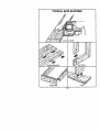
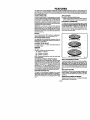
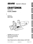
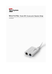
TYPICAL APPLICATIONS
175010 PLATE JOINER
Page 2
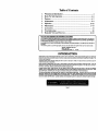
Table of Contents
I.
Warranty and Introduction .......................................................................
2.
3.
Rules For Safe Operation .....................................................................
Features ................................................................................................
4.
Adjustments ..........................................................................................
5.
6.
Operation ..........................................................................................
Maintenance .....................................................................................
7.
Accessories .............................................................................................
8.
9,
Troubleshooting .....................................................................................
Exploded View and Parts List ..........................................................
FULL ONE YEAR WARRANTY ON CRAFTSMAN
3
4-5
6-7
8-9
10-16
17-19
19
20
22-23
PLATE JOINER
Ifthis C raftsman Plate Joiner fails to perform propedydue to a defect in mate dal or workmanship within oneyear from
the date of purchase RETURN IT TO (OR CONTACT) THE NEAREST SEARS SERVICE CENTER I DEPARTMENT
IN THE UNITED STATES and Sears will repair it, free of charge.
It this plate joiner is used for commercial or rental purpueas this warranty applies for only 90 days from the date of
purchase.
This warranty gives you specific legal dghts, and you may also have other dghts which vary from state to state.
SEARS, ROEBUCK AND CO.
DEPT. 817 WA
HOFFMAN ESTATES, IL 60179
INTRODUCTION
Spitne Joiner'/is o_e of the strongest methods of joinery used in woodworking, When glue is properly applied to a spline and
to the jointarea of the wood pieces being connected, a large surface area receives the adhesion properties of the glue. This
forms a very strong joint.
Traditional spline Joiner'/requires cutting slots with a muter or table saw. Smafl, thin strips of wood must then he cut to fit
inside the slots and act as splines.
Newer methods of spitne jokiery use a plate or biscuit joiner to cut precise mating oval slots in adjoining beards. Your new
plate joiner is a fast, simple, and accurate plunge cuttingtool that can be used for this purpose. If can be used to cut slots in
hard wood, soft wood, plywood, particia board, and other pressed woods.
Football shap4_l wafers, called biscuits, are then placed Inside the slots with"glue and used to help line up adjoining
surtames. When a water based glue is used, the biscuitsswell in the joint making an extrem*dy strong and firm bond, White
glue, yellow glue. carpenters glue, hide glue, and kiiphatic resin glue are examples of water based glues.
This bonding technique has trediflo_tallybeen limited to making edge-to-edge joints, However, with the use of your new
plate joiner, biscuitscan now be easily used to connect butt, miter, and T-joints. Biscuit joining can be as stronglu_mortise
and tenon, tongue and groova, standard 8pllne, and doweled joints. In most cases the material around the biacuit will break
before the biscuit Itaeit will break. A greater Igrtge area Ill 8xpoI4rd to glue in a bl_uit joint, rnaidng the seams stronger.
Page 3
RULES FOR SAFE OPERATION
READ ALL INSTRUCTIONS
1,
KNOW YOUR POWER TOOL - Read owner's
manualcarefully,Learn its applications and limitations as well as the specificpotential hazards
related to thistool.
2.
GUARD AGAINST ELECTRICAL SHOCK BY
PREVENTING
BODY CONTACT WITH
GROUNDED SURFACES. For example: Pipes,
radiators,ranges, refrigerator enclosures.
KEEP WORK AREA CLEAN. Cluttered areas
and benchesinvite accidents.
AVOID DANGEROUS ENVIRONMENT. Don't
use power tools in damp or wet locations or
expose to rain. Keep workarea well lit
3.
4.
13.
DON'T ABUSE CORD. Never carry tool by cord
or yank it to disconnect from receptacle. Keep
cord from heat, oil, and sharp edges.
14.
SECURE WORK. Use clamps or a vise to hold
work. It's safer than using your hand and it frees
both hands to operate tool.
15,
DON'T OVERREACH.
Keep proper footing and
balance at all times. Do not use on a ladder or
unstable support
16.
MAINTAIN TOOLS
WITH CARE. Keep tools
sharp at all times, and clean for best and safest
performance. Follow instructions for lubricating
and changing accessories.
5.
KEEP CHILDREN AND VISITORS AWAY. A{I
visitorsshouldwear safetyglassesand be kepta
safe distancefrom workarea. Do not let visitors
contact tool or extensioncord.
17.
DISCONNECTTOOLS.
When not in use, before
servicing, or when changing attachments, blades,
bits, cutters, etc., all tools should be disconnected.
6.
STORE IDLE TOOLS. When not in use tools
shouldbe storedin a dry, highor locked-upplace
- outof the reach of children.
18,
7.
DON'T FORCE TOOL It wiltdothejobbetterand
safer at the rate for whichit was designed.
USE RIGHT TOOL. Don't force small tool or
attachment to do the job of a heavy duty tool.
Don't use tool for purpose not intended - for
example - Don'tuse a circularsaw forcuttingtree
limbs or logs.
REMOVE
ADJUSTING
KEYS
AND
WRENCHES. Form habit of checking to see that
keys and adjusting wrenches are removed from
tool before turning it on.
19.
AVOID ACCIDENTAL
STARTING.
Don't carry
plugged-in tool with finger on switch. Be sure
switch is off when plugging in.
MAKE SURE YOUR EXTENSION CORD IS IN
8.
9.
10.
11.
12.
DRESS PROPERLY. Do notwear looseclothing
or jewelry. They can be caught in movingparts.
Rubbergloves andnon-skidfootwearare recommended when workingoutdoors.Also, wear protactive hair coveringto containlonghairandkeep
it from being drawn intoair vents.
ALWAYS WEAR SAFETY GLASSES WITH
SIDE SHIELDS. Everydayeyeglasseshaveonly
impact resJstsntlenses; they are NOT safety
glasses.
PROTECT YOUR LUNGS. Wear a face or dust
mask if operationis dusty.
PROTECT YOUR HEARING. Wear hearingprotaction during extendedpedods of operation.
20.
GOOD CONDITION.
When using an extension
cord, be su re to use one heavy enough to carry the
currentyour product willdraw. An undersized cord
will cause a drop in line voltage resulting in loss of
power and overheating. A wire gage size (A.W.G.)
of at least 16 is recommended for an extension
cord 100 feet or less in length. A cord exceeding
1GO feet is not recommended. If in doubt, use the
next heavier gage. The smaller the gage number,
the heavier the cord.
21.
OUTDOOR
USE EXTENSION
CORDS.
When
tool is used outdoors, use only extension cords
intended for use outdoors. Outdoor approved
cords are marked with the suffix W-A, for example
- SJTW-A or SJOW-A.
22.
Page 4
KEEP BLADES CLEAN AND SHARP.
blades minimize stalling and kickback.
Sharp
RULES FOR SAFE OPERATION
23
KEEP HANDS AWAY FROM
(Continued)
CUTTING
AREA.
33.
USE ONLY 4 INCH DIAMETER
SPECIRED
BLADES. Do not use blades with incorrect size
holes. Never use b;ade washers or bolts that are
defective, incorrect, or not specified.
NEVER USE IN AN EXPLOSIVE ATMOSPHERE.
Normal sparking of the motor couid ignite flammable liquids, gases, or fumes.
INSPECT TOOL CORDS PERIODICALLY
and if
34.
AVOID cUTnNG
NAILS. Inspect for and remove
all nails from lumber before cutting,
35.
NEVER touch the blade or other moving parts
dudng use,
damaged, have repaired by an authodzed service
facility. Stay constantly aware of cord location
and keep it well away from the rotating blade.
36.
NEVER start a tool when the blade is in contact
with the workpiece,
37,
NEVER lay a tool down before the blade has
come to a compiota stop.
POLARIZED PLUGS. To reduce the dsk of elec-
Keep hands away from blades. Do not reach
underneath work while blade is rotating, WARNING: BLADES COAST AFTER TURN OFF.
24,
25.
26,
INSPECT EXTENSION
CORDS PERIODICALLY
and replace if damaged.
27.
28
29.
38.
KEEP HANDLES
DRY, CLEAN, AND FREE
FROM OIL AND GREASE. Always use a clean
cloth when cleaning. Never use brake fluids,
gasoline, petroleum-based products, or any strong
solvents to clean your tool.
STAY ALERT
AND EXERCISE
CONTROL.
tric shock, this equipment has a polarized plug
(one blade is wider than the other). This plug will
fit in a polarized outlet only one way. If the plug
does not fit fully in the outlet, reverse the plug. If
it still does not fit, contact a qualified eioctdcian to
install the proper outlet. Do not change the plug in
any way.
Watch what you are doing and use common
sense. Do not operate tool when you are tired, Do
not rush,
39.
CHECK
40.
DAMAGED
PARTS.
Before further use
of the tool, a guard or other part that is damaged
should be carefully checked to determine that it
will operate propedy and perform its intended
function. Check for alignment of moving parts,
binding of moving parts, breakage of parts, mounting, and any other conditions that may affect its
operation. A guard or other part that is damaged
should be propady repaired or replaced by an
authorized service center.
30.
31,
32.
When servicing use only Identlcst Craftsman
replacement parts.
SAVE THESE INSTRUCTIONS.
Refer to them
freqLlently and use them to instruct others who
may use this tool. If you loan someone this tool,
loan them these instructions also.
DO NOT USE TOOL IF SWITCH DOES NOT
TURN IT ON AND OFF. Have defective switches
replaced by an authorized service center.
DO NOT OPERATE THIS TOOL WHILE UNDER
THE INFLUENCE OF DRUGS, ALCOHOL, OR
ANY MEDICATION.
GUARD
AGAINST
KICKBACK.
Kickback
oc-
curs when the blade stalls rapidly and the plate
joiner is ddven in the direction opposite blade
rotation. Release switch immediately ifblade binds
or joiner stalls.
m
[_
which can result In imvere eye damage. Before beginning power fool opefat tan, stways wear |
safety goggles of msfotygllmsee with side shields and a full face shield when needed. We |
roeommend
Vision
Safety
for use
over eyeglasses
or standard
safety
glmeyes, I
The
operationWide
of any
power
tool MaSk
can result
in-foreign
objects bstng
thrOWn Into
your
with elde shields, avelloble at Sears Retell Stores.
)
Page 5
FEATURES
Your Plata Joiner has been designed for making fast, accurate, and simple plunge cuts in wood, etc. so that biscuitscan be
used to join two or more boards together. When used pmpedy and only for whet it is intended, thisversatge tool will give you
yearn of troubta-tree berforrnance, it is professlenally engleeered, but its ease of operaiton allewsthe amateur ta preduce work
that is beautiful and precise.
DOUBLE
INSULATED
APPLICATIONS
This toot is double insulated. Double Insulation is a concept
insafely, in electric powertools, which elhelnatas the need for
the usual three wire grounded power cord end grounded
supply system. Wherever there is electric cutTent in the tool
there are two complete sets of insulationto protect the user.
All exposed metal partsare isolatedfrom internal metalmotor
components with protecting insulation.
IMPORTANT - Servicing of a tool with double insulation
requires extreme care and knowledge of the system and
should be performed only by a quaJified sePAceteChniCian.
For service we suggest you return the tool to your nearest
Sears storefor repair. Always useodgtsal factoryredlacement
parts when servicing,
(Use only for the purpose listed below)
1. Cuttingprecise matleg oval slots in hard wood, soft wood,
plywood,pattislaboard, ets. for spllee Jok_eP/edplisatlens.
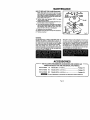
ELECTRICAL
CONNECTION
Yourplate joiner has a precisionbuilhelactdcmotan Itshould
beconneuted to a p<>wersupply that ts 120 vofts, tt0 Hz, AC
only {normal household current). Do nut operate this taol
on direct current (DC). A voltage drop of more than 10
percent will cause a less of power and overheating. If your
plate joiner does not operate when plugged into an outlet,
double-check the power supply.
SWITCH
TO turn your plate joiner "ON", depress the switch trigger,
Release switch trigger to turn your plate joiner "OFF =,
5/8 HORSEPOWER
MOTOR
Your plate joiner has a powerful 5/8 horsepower motor with
sutticient powe rto handle toughcutting jobe. Itdevelops a no
load speed of 10,000 RPM,
CARBIDE
TIPPED
BLADE
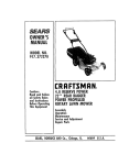
#O : 5/8 tN. X 1-13/16 IN.
Your plate joiner has an 8 tooth carbide tipped blade for
cutting biscuit stets,
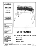
BISCUITS
S_ Figure 1.
Biscuits are available in three standard sizes:
#10 = 13/16 IN. X 2-1116 IN,
#O (5/8 In. x 1-13/16 th.)
#10 (13/16 In. x 2-1116 In.)
#20 (15/16 In. x 2-S/16 in.)
NOTE: Biscuits swell rapidly uponcontact with watar-based
woodworking glues•
ADJUSTABLE FENCE / FRONT HANDLE
#20 : 15/16 IN. X 2-rd16 IN.
Fig. I
DEPTH
Your plate joiner has an adjustable fence. By loosening the
height adjustment knobs, the angle ofthe fence can be set at
angles up to 60_ above and 45° belew 90°, with positivestab
settings in increments of 15°. The height of the fence can be
set between 0 in. - 2 in. with a scale showing 0 in, - 1-1/2 in.
The front handle is a rnokled part of the adjustable fence and
shouldalways be used to guide and balance your plate joiner,
provlding ease of operation and maintaining safe control.
NON-SKID
BACKING
PAD
The fence on your plate joiner is padded with a non-skid
backing pad to hold it stationa_ against the workpisce. It
he_ps prever_ skidding when making cuts. it also prevents
marring ofthe workplece from your plate joiner when making
CutS.
ADJUSTMENT
KNOBS
A spring loaded depth adjustment knob makes it eds_ble to
make proper settit;gs for three standard size biscuits. Fine
adjustments to the cutting depth can be made with two
knuhededjust ment knobskicated behindthe depth acrlustment
knob, Once the correct depth setting has been made for one
biscuit size, the othertwo depth settingswill be automatically
set.
DUSTLESS
FEATURE
The dust box on the rear of your plate joiner provides a dust
collection sylttem. Wood particles are drawn up through a
tunnel in the base and collect in the dust box duitng cutting
operations.
HIQHLIGHTED
INDICATOR
MARKS
Highlighted centadine and line of cut indicator marks have
been provided on your plate joiner.
Page 6
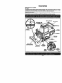
FEATURES
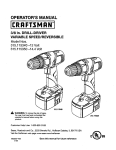
KNOW YOUR
,_e Fibre 2.
PLATE
JOINER
Your plate Joinerhas been shipped €ompletely as_mbled end ready for use. Inspect it carefully to make sure no breakage
or damage has occurred dudng shipping, ff any parts are damsged or missing, contact your local Seam store or Sears
authorized service center to ob(aln replacement parts before attempting to operate your plate J_r_n
ThedU6tboxisalsolnstall6dontherearoftooL
particles, empty dust box often.
Its usewillhelpkeeptheworkareaclean.
For most efficient pick.upof wood
8efo_m8ttempt_g to use eny tool familiarize yourself with all operating features and safety requirements.
_r_l_
CENTERUNE I UNE
Page 7
SWITCH TRIGGER
REAR HANDLE
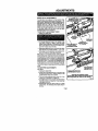
ADJUSTMENTS
DEPTH
OF CUT ADJUSTMENTS
Your plate joiner can be adjusted to three standard cutting
depths to accommodate three standard size biscuits-- #0,
#10, and #20. Adjustments are made by engaging slots o_
depth adjustment knob with tabs on rear base assembly. For
exsmpta, when using a #0 size biscuit, rotate the depth
adjustment knob to the slot marked 0. When usinga #10 size
biscuit, rotate the depth adjustment knob to the slot marked
10, and when using a #20 size biSCUitrotate the depth
adjustment knob to the slot marked 20,
TO SET DEPTH
ADJUSTMENT
_,_
DEPTH
ADJUSTMENT
KNOB
KNOB
1. Unplug your plata joiner.
TABS
KNOBS
REAR BASE
ASSEMBLY
2. Pull knuhad adjustment knobs in the direction of the
arrow shown in figure 3. NOTE: Knobs are spdng
loaded, therfore puIllogthem in the direction of the arrow
shown puts pressure on the spring and reloases pressure from the depth adjustment knob.
PULL AND HOLD TO
ROTATE OEPTH
ADJUSTMENT KNOB
3. Rotate depth adjustment knob until desired slot setting
aligns with tabs on rear base assembly -- 0, 10, or 20.
4. Next release knurled adjustment knob_ applying pressure from the sprthg on depth adjustment knob.
ROTATETO
DESIRED sE'nlNG
IO, OR 20
Fig. 3
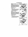
Make a test cut in a scrap piece of wo_d. Fit the correct size
biscuitloto biscuitslot. Ifbiscuit slnt istoo deep ortoo shallow,
fine adjustments to the depth setting can be made by loosening rear adjustment knob and making fine adjustments with
the frontadjustment knob, Turning trent knob forward wiltcut
shallow biscuit slots, Turning front knob backwards will cut
deeper biscuitslots. The biscuit slot should be deep enough
to allow slightly more than one-half ofthe biscuit intothe slot.
This extra room allows for proper alignment ofthe woodbslng
joined.
TO MAKE
FINE
TURN FORWARD
FOR SHALLOW
BISCUIT SLOTS
ADJUSTMENTS
See Figure 4.
1. Unplug your plate Joiner.
2. Loosen rear knuded adjustment knob. This knob isused
as a lock nut or jam nut only, Loosen by twistingit In the
opposite direction away from front knob.
3. Turn front knurled adjustment knob forward for a more
shallow cot, or backwards for a deeper cut.
4. Once desired depth ofcut is reached, held frontknob so
that itwill not move out of adjustment, Next, tighten rear
knob against front knob,
5. Re_heck depth setting by making a test cut in a scrap
piece of wood. Also periodically check depth settingfor
acouracy,
Page 8
Fig. 4
ADJUSTMENTS
FENCE
HEIGHT
ADJUSTMENT
S_e Figure
The adjustable fence on your plate joiner can be moved up
and down to adjust the position of the blade in relation to the
top of the workpiece. A scale on both sides of the fence
indicatesthe height of the fence from the center of the blade.
The fence can be positioned up totwo inches from the center
of the blade. However. the scale and indicator pointcan only
be setup to 1-1/2 in.from the center of the blade. Scale marks
are in iilcrements of 1/16 in.
TO ADJUST
HEIGHT
FRONT HANDLE I
_DJUSTABLE FENCE
SETTING
See Figure 5.
1. Unplug your plate joiner.
2. LooSenthetwoheightedjustmentknohe. NOTE: Loosen
each height adjustment knob approximately one turn.
TO LOWER
ADJUSTABLE
FENCE
3. Slide the fence up or down until the indicator point is
aligned with the desired dimension on the scale.
4. Tighten height adjustment knobs securely.
FENCE
ANGLE
ADJUSTMENT
ADJUSTMENT
KNOB(S)
See Figure
The adjustable fence on your plate joiner can be set at angles
ranging from 60 ° above 90 ° to 45° below 90o, with quick,
accurate positive stops set in 15° increments. A scale is
located on both sides ofthe front handle for identifyingthese
positive stop angles. Each click you hear when rotating the
adjustable fence from one angle setting to another equals a
15° positive stop angle change.
TO ADJUST
ANGLE
SE'i-rlNG ,
SCALE
INDICATOR
POINT
TO RAISE
ADJUSTABLE
FENCE
SETTING
See Figure 6.
1. Unplug your plete Joiner.
2. Loosenthetwoheightadjustment knops. NO'RE: Loosen
each height adjustment knob approximately one turn,
TO LOOSEN
3. Rotste edjustable fence up or down to the desired angle.
4. Tighten height adjustment knobs securely.
TO _GHTEN
Fig. 5
ROTATEADJMSTABLEFENCE
TO DESIRED ANGLE SETTING
Fig. 6
Page 9
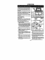
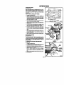
OPERATION
A variety of spllne joints can be made usingyour plate joiner.
The number and size biscuitsneeded for each jointdepends
on the thickness of the wood and the length of the joint, in
general, tbe small #0 b_cuits ehouM be used for mitercuts in
314in. matshels. The larger bizcults shouldbe used for edgeto-edge jolnery.
When joining 1-1/2 in, thick materials, stack two biscuits, one
above the other. For example, joining 2 in. x 4 in. dressed
lumber. See Figure 9. When joining even thicker materials,
use eddltional biscuits, stacked above each other.
When making edge-to_dge jointsfor tab_etsps,wortCenches,
cutting boards, etc. the more biacultsyou use, the stronger
the Jointwill be.
The following sections illustratehow to make vadous spline
joints uelog your plate joiner.
EDGE-TO-EDGE
JOINTS
See Figures 7 and 8.
Edge-to-edge joine_J is one of the most basic and easiest
joints toconstruct. In general, two basic adjustments have to
be made for all biscuit jolnery apptications. One is the depth
of cut and the other is the location of the cut.
HOW
TO MAKE
EDGE-TO-EDGE
CENTERLINE
MARK(S)
UNE OF
CUT WINDOW
TOP VIEW OF PLATE JOINER
JOINTS
Fig. 7
CENTERLINE
1. Unplug your plate Joiner.
2. Prepare the workplecea by laying them slbe by side on a
workber_h in the order in which they will be assembled,
3, Using a square, determine the location of each bizcult
spline joint and mark the ceofer of each Jointby drawing
a line across each workplace. NOTE: Mark the edges 2
In. from the ends ofworkplacee. The jointwill be stronger
if you use multiple biscuits placed close together.
4. Loosen height adjustment knobsand set fence angle at
gO_.
5, Slide the fence up or down until the indicator point is
aIignnd with the destted dimar,_slonon the scale. REMEMBER: The scale indicates the height of the fence
from the center of the blade.
RKIE)
_./'_//
;iF/
_
BISCUIT SLOT{S)
EBOE-' EBOEJO,'E
F,g8
6. Tighten height adjustment knobs securely.
7. Select the correct depth of cut settingto rnatshtbe bizcuit
size you are planning to use. We suggest that you make
a test cut in a scrap piece of wood from the same
workplace it possible.
8. Clamp workplace securely so that it will not move during
the cut.
11. Depress the switchtdggerto turnthe power on your plats
joiner, then push it forward to extend the blade Ints the
wood.
9. Plug your plate joiner into power supply and prepare to
make your first cut. Grasp and hold your plate joiner
securelywtth both handsby the froof and rear handles as
shown on page 2.
14. Once all blscutt slots have been cut, place a biscuit in
each jo_ofand dry assemble the workpteces. Make sure
each joint lines up and fits.
15. Finally.disassemble the workpkscesand place a bead of
glue in each slot. Also, spread a bead of glue over the
entire surface of the joint. Reinsert the b_scuits and
assemble the wottq3k_es. See Figure 8.
10. Place the fence against the board and align the indicator
marks on the fence with the cerderllne mark(e) on the
beard. See Figure
12. When the base assembly bottoms out against the depth
of cut adjustment knob eattlng, pullback releasing pressure on the spdng. Blade will retract from biscuit slot.
13. Repeat this procedure for all desped biscuit slots.
16. Clamp workpieces together until the glue sets up.
Page 10
OPERATION
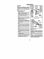
BUTT JOINTS
See Figure 9.
A butt joint is one of the weakest joints in woodworking.
This type of joint is mating the end grain of one board with
the edge grain of another. The Pendingof glee on thistype
of surface Is poor. However, by using biscuits you can
create a very strong joint that gives a modise-and-tonon
effect.
HOW
TO MAKE
BUT[
JOINTS
1. Unplug your plate joiner.
2. Place the two pieces of wood to be joined on a level
workbench. Align them against each other in the arrangement in which they will be assembled,
3. Using a square, determine the location of each biscuit
sptine Jointand mark the center of each joint by drawing
a line across the edges of the two boards.
MULTIPLE
BISCUITS
STACKED
4. Loosen height adjustment knobs and set fence angle at
g0°.
5. Slide the fence up or down until the indicator point is
aligned with the desired dimension on the scale, REMEMBER: The scale indicates the height of the fence
from the center of the blede,
CENTERUNE
MARK(S)
BUTT JOINTS
OFFSET B U1"i"JOINT
6. Tighten height adjustment knobs securely,
7. Select the correct depth of cut settingto matobthe biscuit
size you are planning to use. We suggest that you make
a test cut in a scrap piece of wood from the same
work_ece if possible.
8. Clamp workpiece securely so that if will not move duhng
the cut.
BISCUIT
SLOT
BISCUIT
g. Plug your plate joiner into power supply and prepare to
make your first cut. Grasp and hold your plate joiner
securely with both hands by the trent and rear handles.
t 0. Place the fence egainst the board and align the indicator
marks on the fence with the centedine mark(s) on the
board.
11. Depress the switchtdgger to turnthe power on your plate
joiner, then push it forward to extend the blade into the
wood.
12. When the base assembly bottoms out against the depth
of out adjustment knob setting, pull back rsteasing pressure on the spring. Blede will retractfrom biscuit slot.
13. Repeat this procedure for cutting the slot in the mating
workptsce.
14. Once aft biscuit slots have been cut, place a biscuit in
each joint and dry assemble the workpleces, Make sure
each joint lines up and tits.
15, Finatly, disessemb[e the workpleces andplace a bead of
glue in each slot, Also, spread a head of glue over the
entire surface of the joint. Releserl the biscuits and
assemble the workpieces, See Figure 9.
16, Clamp workpteces together until the glue sets up.
Fig. 9
CENTERUNE
MARK(E)
OFFSET
BUTT JOINTS
see F'tgure 10.
The railsof a table or workbenchare oEen oEset from the front
of the table legs. When offsetsare rsqulred, it ISneces|mry
to cut the slots in the ragsfirst, then re-adjust the fence to cut
the slots in the legs.
Keeping this one exception in mind, the procedure for cutting
offset butt joints is identical to the procedure for cuffing butt
joints.
For example -- It a 1/4 in. offset Is desired, yo_ would mark
the centol_nes for cutting a butt joint as mentioned in the
procedures for cobleg butt joiofs, and cut the sfotsIn the ends
of the rails. Next you would raise the fence 114in. to the
desired offset and cut the slots in the legs.
Page 11
OPERATION
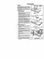
T-JOINTS
l ti/f
See Figures 11-15.
It I|f! |1/1-._
A T-jolot is used when the end of a board is joined to the
face of another board as shown in figure 11. Attaching
shelves to bookcases and inner support braces to frames
are typical applications, Actual cutting of a T-jofnt is as
slmpla as any other cut. However, itis cdtlcetthat you mark
the centedloes, mark the intersection points for each slot,
and cut each slot correctly.
HOW
TO MAKE
_/_
MARK(S)
BISCUITlS)
T-JOINTS
1. Unplug your plate Joiner.
2. Piece the two places of wood to he joined on a level
workheqx:has shown in figure 12, The inside face of the
vertical board should he facing up.
3. Determine the location of each biscuit jointand mark the
centedloes on each board as shown. The centedines for
both boards must line-up with each other. Measure
carefully, these measurements must he accurate and
precise. TIP: Measure twice and cut once, in addition
to the centedinaslining up, the spacingofthe biscuitslots
from side-to-side must also match.
BISCUIT
SLOT(S)
T-JOINT
Fig. 11
HORIZONTAL BOARD
4. Plug your plate joiner into power supply and cut slots in
etl boards that requireendsiots. SeeFigure 13 Follow
procedures explained in "Edge-To-Edge Joints", Set
fence angle at 90°, setfence heightat desired dimension
on the SCale,select the correct depth ofcut settingfor the
biscuit size you plan to use, clamp workpiece securely,
then cut each slot at the marked centedioe intersection,
BISCUIT SLOT
CBNTERLINE
MARK(S)
BOARD
CENTERUNES
5. Next, you must remove the adjustable fence from your
plate joiner in order to cut slots intothe face ofthe vertical
board.
TO REMOVE ADJUSTABLE PENCE:
6. Unplug your plate Joiner.
7. Loosen and remove halghtedjusting knobs, square heed
bolts, angle edj ustmeet lockplates, and adjuStablefence.
See Figure 14.
8. Place your plate joiner on vedical board as shown in
figure 15 and align indicator marks on base assembly
with cerdedine on verticet board.
VERTICAL BOARD
Fig. 12
HORIZONTAL BOARD
9. Place a straight piece of wood on the vedical board and
securaly clamp itflush against the base assembly, This
piece of wood is used for a fence or guide, It must he
square with the sides of the vertical board and parallel
with the centedine.
10, Align cantsrline on bottom ofhese assembly with marked
intersectionfor biscuit slot.
11, Plug your plate joiner into power supply and prepare to
cut slot,
12, Depress the switchtdgger to turnthe power on your plate
joiner, then push it down to extend the blade into the
wood
13. When the base assembly bottoms out against the depth
of cut adjustment knob setting, pullback releasing presCLAMP
sure on the spring. Blade win retract from biSCuitslot,
14, Repeat this procedure for cutting all required slots in
vertical boards,
Page 12
TO CUT END SLOTS IN
HORIZONTAL BOARDS
Fig. 1
OPERATION
T-JOINTS
(Continued)
ANGLE
ADJUSTMENT
15. Once.aU slots have been cut, place a biscuit in each joint
and dPJassembts the worlds.
Make sum each joint
lines up and fits.
16, Rnally, dlaassembfe the workpleces end ptsce a bend of
glue In each slot. Also, spread a bead of glue over the
entire sudace of the joint. Reinsert the biscuits and
assembla thawo_s,
S6eFigure 11.
17, Clamp workplaces together untUthe glue sets up.
Upon complatio_ of T-joint cutting operation, reassemble
edjustable fence by reve rsirlg"TO REMOVE ADJUSTABLE
FENCE" procedure, Align angle adjustment lock plates with
matingangle adjustment plates. NOTE: Angle adjustment
plates are located in adjustable fence, Place them in groove
on each side of plate joiner as shown in figure 14, Once
properlyaligned, secure ever/thing in place with square bolts
and height adjusting knobs.
HEIGHT
ADJUSTMENT
KNOB(S)
HEADBOLT(S)
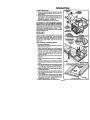
MITER JOINTS
SeeFigures16-19.
ANGLE
ADJUSTMENT
LOCKPL.ATE(B)
GROOVE(S)
BOTTOM SIDE OF BASE ASSEMBLY
There ere two types of miter joints that can be made using
biscuits: flat miters and edge miters, Flat mite_ ate used
when making picture frames, Edge miters are used when
making boxes or things where you don't want to show the
end grain of the wood, NOTE: Bug joints show the end
gndn in wood.
HOW
TO MAKE
FLAT
MITER
ON WORVd_ECE
HORIZONTAL
BOARD
CENI_RLINE
MARl _
JOINTS
1. Unplug your plate Joiner.
2. Place the pieces of wood to be joined on a lavel workbench as shown in figure 16.
3. Using a combination square, draw a line through the
center of each Joint perpendlaular to the mitered edges,
4, Set fence angle at 90°, set fence height at desired
dimensidn on the scale, select the correct depth of cut
setting for the biscuit size you plan to use, end clamp
workplace securely.
5. Align indicator mark on fence with the centedine on the
workplace.
6, Plug your plate joiner into power supplyand prepare to
cut sint.
7, Depress the switchtdgger to turnthe power on yourplate
Joiner,then push It fefwald to extend the blade into the
wood.
Fig. 14
INDICATOR
MARK
CLAMP
8, When the bese assembly bottoms o_ against the depth
ofcut edjuetment knob setting, puffback releasing piessure on the spdng. Blade will retract from biscuit sidt.
9, Repeat this procedure for cutting mating slot and all
required m_fer joint slots,
10. Once all slots have been cut, place a biscuit in each joint
and dry assemble the workpleces. Make sureeach joint
lines up and fits,
11, Finatty, disassemble the wodq)laces and place a bead of
glue in each sint, Also, spmed a bead of glue over the
entire surface of the Joint. Roinsett the biscuits and
assemble the workpleces, SeeFigure 16.
12. Clamp workpleces together untilthe glue sets up,
Page 13
VERTICAL BOARD
TO CUT $LO'I_ IN VERTICAL BOARD6
FLAT Mn'ER JOINTS
Fig, 15
F_.
OPERATION
HOW TO MAKE
EDGE
MITER
JOINTS
1. Unplug your plate Joiner.
2. place the pleces of wood to be joined on a level work*
bench as shown in figure 17.
3. Mark centedine of the joint on each board.
l'/_'_'/-'P"
e_scurr
///F/
-s T
4. When making edge miter joints _
workpleces that
have different thicknesses, clamp securely to a workbench with the long sides up. This will assure that the
outside surfaces will match, See F/gum 18.
5. Loosen height edjusttng knobs and set fence angle at
45 ° ,
6. Slide the fence ug or down untilfence beight I$at deslrnd
setting,
7, Tighten height adjustment knobs securely,
8. place your plate joiner on workplece with the adjustable
fence resting on the long side of workplece as shown in
figure 18, The base or vertical fence should be agak_st
the mitered edge of the wod_ece.
9. Recheck fence height seffing to make sure it will not cut
through the workplece.
10. Align indicator mark on fence with the centedlne on the
workpiece. Make sure the base or vettk:_d fence is
pressed fiat against the mitered edge of the work_ece,
11. Plug your plate joiner into power supply and prepare to
cut slot.
_"
C_NTERL_N I=
MARK(S)
BISCUIT
EDGE MITER JOINTS
Fig. 17
CUTTING EDGE I_'rER 8LOT
FROM LONG 81DE OF WORKPIECE
t2, Depressthe switohtdgger toturn the power on your plato
joiner, then push tt forward to extend the blade into the
wood.
13. When the base assembly bottoms out against the depth
ofcut adjustment knob setting, pullhack releas_ugpre_
sure on the spring. Blade will retract from blecult slot.
14, Repeat this procedure for cutting mating slot and a_l
required miter joint slots.
15, Once all slots have been cut, place a biscuitin each Jclnf
and dry assemble the workpieces, Make sure each joint
lines up and fits.
16, Finally, disassemble workpieces and place a bead of
glue in each slot, ALSO,spread a bead of glue over the
entire surface of the joint. Reinsed the biscuits end
assembleworkpieces, See FIgure 17.
17, Clamp workpleces together untilthe glue sets up.
CuTIrlNG EDGE MITER SLOT
FROM SHORT SIDE OF WORKPIECE
if the woricplecesare the same thlokeass, clamp securely to
a workbench with the short sides up, S6e Figure 19. Set
adjustable fence angle at 45 ° above the gO° setting on the
scale. Place your plate joiner on the workplece wtth the
adjustable fence resting on the short side of the workplace
and the base or vertical fence against the rtdtered edge of the
workplece, Follow steps 9-17 above to cut required slots,
REMEMBER: Before cuttJn9 slots, make sure blade will not
cut thrOughthe workpiece and that both the vertical and
horizontal fences are pressed flat agalmd the mitered edge
and face of the workplace.
I
J
Page 14
Fig. 19,
OPERATION
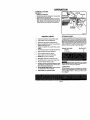
AUXILIARY
FENCE
Sse Figures 20.21.
When cutting biscuit slots in workptaces lass than 1-1/2 in.
wide. it is necessary to make an 8_iliew fenoe end mount it
to the bottom of the adjustable fence. Thb fence will provide a positive stop for the height setting of these small
workpieces.
HOW TO MAKE
AUXlUARY
FENCE
1. Unplug your plate Joth_r.
2. Cofathlnpieceofwood3.5/81n.xS-1/4in.
NOTE: The
thickness ofthe wood will0ause the scale on the vertical
fence of your p_ate_
*,0 rte Ir_oneof. He_t _mant settinge must alk>wforthe thicknessofthe suxlliefy
fence when preparing to oof slots.
3. Cut a notch as shown in figure 20 for "Alwing indk'.ator
mark and canted(he markings on boards,
4. Place euxllleP/1ante against boEom ofadJustat_efence.
SGe Figure 21.
5. Ustng screw holes In adjustable fence for a ptatem, math
screw boie Iocatlor,s on auxilier/fence,
NOTE: See
figure 20 for screw hole lOCationsand dimensions.
6. Drill 3/16 In. screw hotas in eux_lta_yter_e. Screw holes
must be countersunk on the bottom so that sorewheeds
will he flush with or below the surface of the auxiliary
fence.
.
1
HEX NUT(E)
WASHER(E)
7. Secure auxilierj fence ta adjuetabie tanoe with3/16 In. x
3/4 in. fiat heart machine _Tews. washen_, and hex nuts
as shown In figure 21.
8. Tighten screws securely, making sure screw heads are
flush or subfiush with bottom surface of auxiliary fence.
DUSTLESS FEATURE
see Figures 22.23.
The dust box Io_tad ¢n the rstu of your pinta Joinerprovides
s duet ¢olieoflon system. Wood particiel are drawn up
throughs tunne_ in the base and collectIn the rtustbox dudng
cuttingoheratione. For more efficient operation, empty dust
box when half full,
TO REMOVE
DUST
BOX FOR
EMPTYING
SCREW(S)
AUXlUARY
FENCE
Fig. 21
see Figure 22.
1. Unplug your plate joiner.
2. TO reiease rtust box. depress tshe _ocatod on each side
of dust box as shown by the CHOWSin figure 22.
3. Slide dust box to the rear of plate joiner is shown by the
arrow in figure 22. and remove.
4. DO NOT press on the screen matadel withyour hand or
fingers. Screen rnatadel can be damaged. NOTE:
Screen matedal is located on the sides end reel of dust
box.
5. DO NOT break tabs that secure dust box to plate joiner.
6. Empty dust box.
DUST
BOX
SCREEN
TO
_.REMOVE
DUST BOX
OPERATION
TO INSTALL
DUST
BOX
GROOVES
See Figure 23,
DOS .°o
1. Unplug your plate joiner.
2. Realigrldust poxwithmarof plate joiner, Groovesladust
box align with rails on plate joiner.
3. Slide dust box on plate joiner as shown by the arrow in
figure 23, YOUwill feel a soft click as the tabs snap into
place, NOTE: As mentioned previously, be careful not
to break the tabs that secure dust box to plate joiner,
Fig. 23
HELPFUL
HINTS
EXTENSION
CORDS
/
Always clamp workplace securely before cutting.
/
A safe operator Is one who thinks ahead.
/
Always wear eye protection when cutting slots.
/
Make set-upadjustments carefully. Then doublecheck.
Measure twice and cut once.
The use ofany extension cord willcause some loss of power,
TO keep the loss to a minimumand to prevent tool overheating, follow the recommended cord sizes on the chart below.
When tool is used outdoo,'s,use only extension cords suitable for outdooruse and so marked. Outdoor use extension
cords are marked with the letters 'WA" on the cord'sjacket,
Extension cords are available at Sears Retail Stores,
J
Always dry assemble your project before gluing it
together.
Extension
,/
The more biscuits used, the stronger the joint will be.
/
Keep blade clean and properly sharpened.
/
Don't let familiarity make you careless.
,/
Study all safety nJlas and do the job safely.
/
NEVER place your hands in jeopardy.
/
Make certain clamps can't loosen while in use.
/
Test dlfficuff set-ups on scrap--Don't waste lumber.
/
Plan each operation before you begin.
/
Provide for smoother operation by cleaning your plate
jolaer frsquendy. Sheke plete joiner or blowwith an air
Jetto remove wood particle build*up.
,/
dO NOT ABUSE POWER TOOLS. Abusive practioes
can damage tool as well as workpiece.
/
"n,IINK SAFETY BY THINKING AHEAD,
Cord
Length
Wire
Size A.W.G.
0-25 Feet
18
25-100Feet
16
t_rr_J_l
Keep extension cords away from the cutting
area and position the cord so that it will not get caught on
lumber, tools, etc. dudng cutting operations.
LUBRICATION
All of the bearings in this tool are lubricated with a sufficient
amount of high grade lubricant for the life of the unit under
normal operating conditions. Therefore, no further lubrication is required.
Page 16
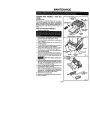
MAINTENANCE
CLEANING
BASE ASSEMBLY
I DUST BOX
ADJUSTABLE
FENCE
TUNNEL
See Figures 24-26.
After extended use, wood particles and resin may build up
inside the base assembly of your plate joiner and clog the
path for wood particles going into dust box. Wood particles
packing up in thisarea, not only defeats the dustless feature
of your plate joiner, it also makes cutting biscuit slots more
difficult.
CREWDRIVER
HOW TO CLEAN BASE ASSEMBLY
FRONTBASE
1, Unplugyour platejoiner.
ASSEMBLY
SCREW
HOLE
SHOWN
2. Remove dustbox. Depress tabs on each sideof dustbox
and slide it to the rear of plate joiner to remove.
3. Place your plate joiner upside down on a workbench as
shown in figure 24.
4. Using a screwdriver remove the two screws securing
front base assembly,
5, Pull adjustable fence in the direction shown by the arrow
in figure 24 and remove front base assembly.
6, Using a pair of neodle nose pliers, stretch and release
springs from tabs on bearing plate. See Figure25+
7. Push adjustment rod away from bearing plate and remove rear base assembly.
g. With front and rear base assembfies removed, place your
plate joiner upside downon a workbench andclean wood
particles and resin from blade, bearing plate and surrounding areas,
WITHOUT
DUST
BOX
Fig. 24
ROD
BLADE
BEARING
PLATE
TAB(S)
Fig 25
FRONT
_Bo
aware of cut hazard, carbide tips on
blade =re sharp.
9. Clean wood particlesand resin from slotsand surrounding areas on frontand rear base assemblies. See Figure
26. Apply a thin coat of general purpose grease in slots
or on beadng plate where base slides.
10. Replace rear base assembly. Position adjustment red in
its proper place as shown in figure 25.
11. Secu re rear base assembly in place withthe two springs.
Hook one end of each spring in notch on each side of
base assembly. Using needle nose priers, stretch each
spring and hook it over tabs on bearing plata.
12. Reassemble front base assembly.
t 3, Replace screws and tighten securely with a screwdriver.
14 Remove screwdriver.
Fig. 26
Page
17
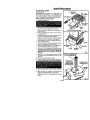
MAINTENANCE
BLADE
REPLACEMENT
ADJUSTABLE
See Figures 27-30,
After extended use, the blade on your plate joiner may
become dull and need replacing. If yOU accidentally hit a
nail or other blunt object, it willbreak the carbide tips on the
blade. These situations also require replacing the blade.
HOW
TO REPLACE
THE
TO
BLADE
1. Unplug your plate joiner,
FRONT BA_
ASSEMBL
SCREW
HOLE
2. Removedust bex, Depresstabsoneachsideofdustbox
end slide it to the rear of plate joiner to remove.
3, Place your plate joiner upside down on a workberlch as
sho_n in figtJ_e 27.
SHOWN WITHOUT DUST BOX
4. Using a screwdriver remove the two screws securing
front base assembly¸
5, Pull adjustable fence in the directiofl shown by the arrow
in figure 27 and remove front base assembly,
6, Using a pair of needle nose pliers, stretch and re_ease
springsfrom tabs on bearing plate. See Figure 28.
7. Push adjustment rod away from bearing plate end remove fear base assembly,
8. Withbaseassembliesremoved, placeplatejoinerupsxte
down On a workbench as shown in figure 29.
9. Pidce a #2 Phillips screwdriver or 1/4 in, diameter pin in
one of the two holes provided in bearing plate,
10. Place one of the non-cutting teeth located behind each
carbide tipped cuftingtoote against the screwdriveror pin
end lock blade preventing itfrom rotating. DO NOT lock
blade against one of the cutting teeth. Carbide Bps
will break,
11. Using a 3/16 in, hex key, remove blade screw, NOTE:
Turn idade screw counterclOCkwise to remove, See
Figure 30.
12. Remove outer blade washer and blade,
NOTC
ROD
BLADE
BEARING
PLATE
Fig.:
NON'CUTTING
TOOTH BEHIND
CARBIDE TIPPED
cLn-nNG TOOTH
CARBIDE TIPP
CUTTING TOO'
•
Place inner blade washer
30.
15,
Place
new
on gear spln_e.
blade ot_to shoulder
secure with outer blade washer
NOTE:
See Figure
of blade washer
and
and blade screw,
Blade screw fits into cupped
TAB(S)
#2 PHILLIPS SCREWDRIVER
OR 1/4 IN. DIAMETER PIN
13, Clean wood particles and resin from blade washer, dust
boxarea, base assembly slots,and all surroundingparts.
14.
Fig, 2
side of outer blade
washor.
Page 18
BEARI
MAINTENANCE
HOW
16,
17,
18.
19.
20.
21.
TO REPLACE
THE
BLADE
(Continued)
RIt;OvE
ooTEo
NOTE: Bade teeth point toward the dght of the plate
joiner when hem in normal operating position, The direction of €of•don is marked on the blade, An arrow on the
bottom of the front base assembly also indicates direction of rotation, See Figure 2Z
Tighten blade screw securely. NOTE: "rum blade
screw clockwise to tighten,
Replace rear base assembly, Positionadjustment rod in
its proper place _zsshown in figure 28,
Secure rear hese assembly in place with the two spdngs.
Hook one end of each spring in notch on each side of
base assembly, Using needle nose pliers, stretch each
spring and hook it over tabs on bearing plate,
Reassemble front base assembly.
Replace screws andtighten securely with a screwdriver.
Remove screwdriver.
T,&O.
_BLADE
Fig. 30
GENERAL
Only the parts shown on pads list, page twenty three, ere
intended to be repaired or replaced by the customer. All
other parts represent an important part of the double insuiation system and should be serviced only by a qualified
Sears service technician at an authorized service facility,
Avoid using solvents when cleaning plastic parts. Most
plastic_=are susceptible to vadous types of commercial sotvents and may be damaged by their use. Use clean cloths
to remove dirt, dust, oil, grease, etc.
When electric tools are used on fiberglass it has been found
that they are subject to accelerated wear and possible
premature failure, as the fiberglass chips and gtindingsare
highly abrasive to hearings, brushes, commutator, etc,
Consequently it is not recommended that this tool be used
for extended work on any fiberglass material, During any
use on fiberglass it is extremely important that the tool is
cleaned frequently by blowing with an air jet.
ACCESSORIES
THE
FOLLOWING
WERE
Item No, 9-25424
RECOMMENDED
AVAILABLE
#O
AT THE
ACCESSORIES
TIME
THIS
MANUAL
ARE
WAS
CURRENT
AND
PRINTED.
Blscults (5/8 in. • 1-13/16 in.) .................................................
Package of 50
Package of 50
Item NO. 9-25425
#10
Biscuits (13/16 In, x 2-1116 in.) ...............................................
Item No. 9.25426
#20
Bllcuite (15/16 in. • 2-5/16 in,) ......;_ ...................................... Package of 50
_The
use of attachments or accessories not listed above might be hazarrtous.
Page
19
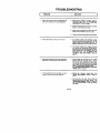
TROUBLESHOOTING
t
PROBLEM
1.
SOLUTION
Biscuitsdo not fit slots. Biscuits not fittingslots may
also cause misalignment of boards being joined.
J
Biscuit slots are too deep or too shallow. Make fine
edjustments to depth setting. Bee "TO MAKE FINE
ADJUSTMENTS" seoflen on page 8.
B+
Biscuitthickness may be out oftolerance. Compress
biscuitsin a vise if they are too thick.
C.
Check to see if biscuitsare the correct size for the
size slots that have been cut: #0, #10, or #20.
Check to see it biscuitshave gotten wet and swollen.
2.
Wood particles begin to backup on front of unit.
Dust collection system is not functioning probedy+
Dust boxmay he full. Empty dustbox often. See"TO
REMOVE DUST BOX FOR EMPTYING" and "TO
INSTALL DUST BOX" sectionson pages 15 and 16.
B.
The tunnel in the base may he clogged preventing
wood particles from being drawn into the dust box.
Remove front and rear base assemblies and clean
blade, beadng plate, base assembly slots, and
surrounding areas.
See "CLEANING BASE
ASSEMBLY / DUST BOX TUNNEL" section on
page 17.
3.
Blade becomes difficulttopush in when cuttingslats.
Blade does not retract propedy when cottleg slots.
A.
WOOd particles and resin have built up on base
assembly slots and surrounding areas, Remove
front and rear base assemblies and clean blade,
bearing plate, base assembly slots and surrounding
areas, Apply a thin coat of general purpose grease
in s!ots oron beadng plste where base slk_es,
See "CLL6J_IING BASE ASSEMBLY / BUST BOX
TUNNEL" section on page 17,
4.
Cutting performance is poor and there is a loss of
power or stalling of motor when cuffing slots.
A.
Blade is dull. Sharpen or replace blade. See
"BLADE REPLACEMENT" section on pages 18
and 19.
B,
Resin has buiif up on blade. Remove b_ade and
ck_m bkldo with gum and pitch remover, See
"BLADE REPLACEMENT' section on pages 18
and 19 for removing blade to clean and replacing
clean blade.
Page20
NOTES
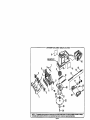
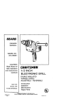
CRAFTSMAN
PLATE JOINER - MODEL NO. 315.175010
SEE NOTE "A"
8\
NOTE "A" -- The ammmbly shown represents an important pert of the Double Insulated System. To avoid I_e poiIIbillty
to _e syntm_ /
sl_mld be parfonned by your nearent Smri Reflalr Cer,ter. Contant your nmrest Slers Rntall _
Page 22
of a_wi_m
or damage
CRAFTSMAN
I
PLATE JOINER - MODEL NO. 315.175010
yourPLATEJOINERorwhenonderi_lrepabparts.
Themodelnumberwillbefoundona plateattachedtothemotorbe,JSl_g,
Alwaysmer_ionthemodelnumberinJl cofl_spondence
regardlng
I
SEE BACK PAGE FOR PARTS ORDERING INSTRUCTIONS
PARTS LIST
Key
No.
Number
De_
1
971484001
Adjusleble Fence I Front Handte ........................... 1
Quart.
2
999529oo1
H_g_tAdjus_nent
Knob
........................................
2
3
4
5
971503-002
971483-001
9714_1
Ang_Ad_stnlentP_
.........................................
Non-Skid BacldngPad ..........................................
Front Base .............................................................
6
7
971 _
623166-002
Angle Adjustment Lock Plate ................................ 2
Eo_t(#1/4-20 x 3/4 in. Sq. Hd.) .............................. 2
8
9
10
972715-000
971476001
971475-001
Gear And Spindle Assembly ................................. 1
Data Plate ................ ,............................................. 1
Dust Box ................................................................
1
11
12
13
14
961244-001
971490-(_1
971473-(_1
703493-811
Logo Plate .............................................................
Spdng ....................................................................
Adjustment Rod .....................................................
Washer -STD551210 ..........................................
1
2
1
1
15
16
17
18
19
971499-001
971498-001
971497-001
623275003
971480001
Compression Spdng ..............................................
Knuded Adjustment Knob ......................................
Depth Adjustment Knob ........................................
" Screw (#10-24 x 3/4 in. Fil. Hd.) ............................
Rear Base .............................................................
1
2
1
2
1
20
21
22
23
972714-000
968703011
971478-001
973606-001
Bearing Plate With Beadng ...................................
* Screw (#8-32 x 3/4 in, Pan Hd.) ............................
Blade .....................................................................
Outer Blade Washer ..............................................
1
4
1
1
24
25
26
975100-001
971481-001
971491-002
972000-339
2
1
1
Blade Screw (Includes Key No. 23) ....................... 1
Warning Label ....................................................... 1
Inner Blade Washer ............................................... 1
Owner's Manual
• Standard Hardware item - May Be Purchased Locally
Page 23
** Available From DIv,96 -- Source g_O.00
/
J
For repair of major brand appliances In your own home...
no matter who made it, no matter who sold it!
1-800-4-MY-HOME
sMA.ytime,
dayornight
(1-1100-469-4663)
www,sesrs,com
To bringin productssuchas vacuums,lawnequipmentand electronics
for repair,call for the locationof your nearest Sears Parts & Repair Center,
1-800-488-1222
An_ime,
dayor night
www.sears.com
For the replacement parts, accessories and owner's manuals
that you need to do-it-yourself, call Sears PartsDIrectS'_
1-800-366-PART
(1-800-366-7278)
6am- 11p.m.CST,
7 daysaweek
www.sears.congpartsdlrect
To purchase or inquire about a Sears Service Agreement:
1-800-827-6655
7 a.m. - 5 p.m. CST, Mon. - Sat.
Parapedirservicio
dereparaci_._
a domici]io,
yparaordenarpiezasconentregaa domlcilio:
1-888-SU-HOGAR=_
(1-888-784-6427)
AuCanada pour serviceen fran_ais:
1-877-LE-FOYER
_
(1-877-533-6937)
[
H r]
O Re_
@ Sea_,
_
and Co.
• Mama _
T,_rk
/ _ Tr_
/ _
o( Sears, RO_
MI.Cx de Fttbrtca de _r_
and Co
P,oeboQk and CO