1
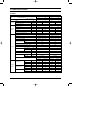
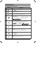
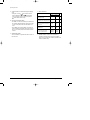
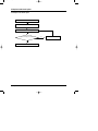
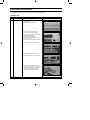
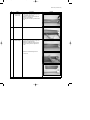
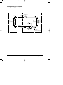
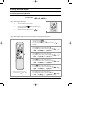
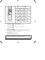
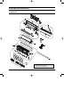
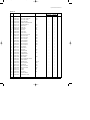
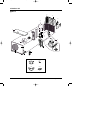
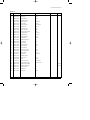
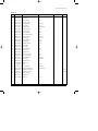
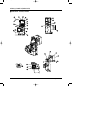
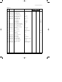
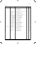
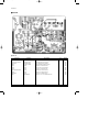
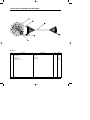
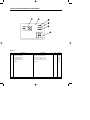
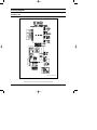
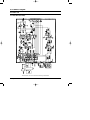
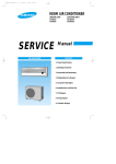
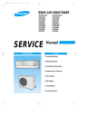
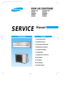
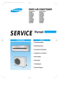
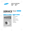
DB98_16341A(2)_co
04/2/9 4:27 PM
Page 3
ROOM AIR CONDITIONER
INDOOR UNIT
OUTDOOR UNIT
SH18AP0
SH24AP6
SH18AP0X
SH24AP6X
SERVICE
AIR CONDITIONER
Manual
CONTENTS
1. Product Specifications
2. Operating Instructions
3. Disassembly and Reassembly
4. Refrigerating Cycle Diagram
5. Set Up the Model Option
6. Exploded Views and Parts List
7. PCB Diagram
8. Wiring Diagram
9. Schematic Diagram
DB98_16341A(2)_SH18AP0
04/2/9 4:35 PM
Page 1
1. Product Specifications
1-1 Table
Model
Item
Cool
Power Source
Heat
220-240V~,50Hz
Capacity
Performance Air Circulation (High)
220-240V~,50Hz
kW
5.1
5.8
6.8
7.0
m3/min
13.0
13.5
14.0
14.5
2.5
3.0
Available Voltage Range
V
198~264
198~264
A
8.3
8.1
10.8
11.2
Power Input
kW
1.81
1.80
2.42
2.49
Power Factor
%
94.8
96.6
97.4
96.7
W/W
2.81
3.22
2.81
2.81
Compressor Locked Rotor Amperes
A
Controls / Temperature Control
Control Unit
Timer
Fan Speed (Indoor / Outdoor)
Airflow Direction (Indoor)
40
58
Microprocessor / Thermistor
Microprocessor / Thermistor
Wireless remote control
Wireless remote control
24-Hour ON / OFF
24-Hour ON / OFF
3 Steps and Turbo / 2 Step
3 Steps and Turbo / 2 Step
Manual
Manual
Auto
Auto
Rotary(Samsung)
Rotary(Samsung)
Horizontal
Vertical
Compressor
Refrigerant / Amount Charged at Rating (R410A)
Refrigerant Control
Operation Sound
1,250g
1,550g
Capillary tube
Capillary tube
Indoor Hi/Mi/Low
dB-A
48 / 46 / 44
48 / 46 / 44
Outdoor-Hi
dB-A
58
61
Refrigerant Tubing Connections
Flare type
Flare type
m
15
20
Narrow Tube
(in.)
6.35(1/4")
6.35(1/4")
Wide Tube
(in.)
12.70(1/2")
15.88(5/8")
Max. Allowable Tubing Length
Refrigerant Tube Diameter
Optional / Hanger-plate
Refrigerant Tube Kit / Accessories
Unit Dimensions
Dimensions
&
Weight
Heat
Liters/h
Energy Efficiency Ratio
Features
Cool
Moisture Removal (High)
Running Amperes
Electrical
Rating
SH24AP6
SH18AP0
Package Dimensions
Weight
Samsung Electronics
Optional / Hanger-plate
Indoor unit
Outdoor unit
Indoor unit
Outdoor unit
Height
mm
315
620
315
638
Width
mm
1,080
787
1,080
880
Depth
mm
205
320
205
310
Height
mm
286
692
286
704
Width
mm
1,151
909
1,151
1,023
Depth
mm
397
444
397
413
Net
kg
13
45
13
63
Shipping
kg
16
50
16
68
1
DB98_16341A(2)_SH18AP0
04/2/9 4:35 PM
Page 2
1-2 Pressure Graph
■ 18K BTU
32.4/24.0
30.6/22.5
28.8/21.0
Low pressure(kg/cm2G)
9
27.0/19.0
8
24.0/17.0
21.5/15.0
7
Indoor inlet air D.B. temp(˚C)
10
6
20
25
30
35
40
45
Outdoor inlet air D.B. temp(˚C)
■ 24K BTU
10
32.4/24.0
30.6/22.5
Low pressure(kg/cm2G)
9
24.0/17.0
8
21.5/15.0
7
Indoor inlet air D.B. temp(˚C)
28.8/21.0
27.0/19.0
6
20
25
30
35
40
45
Outdoor inlet air D.B. temp(˚C)
2
Samsung Electronics
DB98_16341A(2)_SH18AP0
04/2/9 4:35 PM
Page 3
2. Operating Instructions
2-1 The Feature of Key in remote control
No
1
NAMED OF KEY
FUNCTION OF KEY
(On/Off)
On/Off button.
Press the
button to stop or run the air conditioner.
(UP)
Temperature adjustment button(UP).
To increase the temperature by the pressing the temperature button.
(DOWN)
Temperature adjustment button(DOWN).
To decrease the temperature by the pressing the temperature button.
2
3
Mode selection button.
Each time you press this button
Mode is changed in the following order
: Auto Mode
: Fan Only
: Cool Mode
: Heat Mode
: Dry Mode
Fan speed adjustment button.
Each time you press this button, FAN SPEED is changed in the following order.
4
Low
Medium
High
Automatic(rotated :
5
Swing button.
It adjusts the airflow to upward and downward.
6
Turbo button.
The air conditioner cools or heats the room as quickly as possible.
After 30minutes, the air conditioner is reset automatically to the previous mode.
7
Energy saving button.
If you wish to save energy when using your air conditioner, select the Energy saving
mode with the
button.
8
Sleep button.
The sleep timer can be used when you are cooling or heating your room to switch the
air conditioner off automatically after a period of 6 hours.
Samsung Electronics
)
3
DB98_16341A(2)_SH18AP0
04/2/9 4:35 PM
Page 4
Operating Instructions
No
9
10
NAMED OF KEY
FUNCTION OF KEY
Anion button.
Press the
button to generate ion from the air conditioner.
On Timer button.
The On Timer enables you to switch on the air conditioner automatically after
a given period of time that is from 30 minutes to 24 hours.
To set the operating time, press the
time display.
11
Off Timer button.
The Off Timer enables you to switch off the air conditioner automatically after
a given period of time that is from 30 minutes to 24 hours.
To set the operating time, press the
time display.
12
4
button one or more times until the required
Timer Set/Cancel button.
After setting On Timer or Off Timer, press the
And press the
13
button one or more times until the required
button to set it completely.
button again to cancel On Timer or Off Timer set.
Digital On/Off button.
If you want to turn off the display during operation press the
button.
Samsung Electronics
DB98_16341A(2)_SH18AP0
04/2/9 4:35 PM
Page 5
Operating Instructions
2-1-1 Name & Function of Key in remote control
1.
AUTO MODE : In this mode, operation mode(COOL,
HEAT) is selected automatically by the room temperature
of initial operation.
Room Temp
Operation Type
Tr≥ 21°C+∆T
Cool Operation (Set Temp:24˚C+∆T)
21°C +∆T>Tr
Heat Operation (Set Temp:22˚C+∆T)
∆T= -1°C, -2°C, 0°C, +1°C, +2°C
∆T is controlled by setting temperature up/down key of
remote control
2.
COOL MODE : The unit operates according to the
difference between the setting and room temperature.
(18°C~30°C)
3.
HEAT MODE : The unit operates according to the
difference between the setting and room temperature.(16°C~30°C)
*Prevention against cold wind : In order to prevent the
cool air from flowing out at the heat mode, the indoor fan
does not operate or operates very slowly in the
following cases. At this time, the indoor heat exchanger
will be preheating.
- For 3~5 minutes after the initial operation
- For deicing operation
- The operation of an indoor fan in accordance with
the temperature of an indoor heat exchanger
The temperature of
indoor heat exchanger
DRY MODE : Has 3 states, each determined by room
temperature.
The unit operates in DRY mode.
*Compressor ON/OFF Time is controlled compulsorily
(can not set up the fan speed, always breeze).
*Protective function : Low temperature release.
(Prevention against freeze)
5.
TURBO MODE : This mode is available in AUTO, COOL,
HEAT, DRY, FAN MODE.
When this button is pressed at first, the air conditioner is
operated ''powerful'' state for 30 minutes regardless of the
set temperature, room temperature.
When this button is pressed again, or when the operating
time is 30 minutes, turbo operation mode is canceled and
returned to the previous mode.
*But, if you press the TURBO button in DRY or FAN
mode that is changed with AUTO mode automatically.
6.
SLEEP MODE : Sleep mode is available only in COOL or
HEAT mode.
The operation will stop after 6 hours.
*In COOL mode : The setting temperature is
automatically raised by 1°C each 1hour When the
temperature has been raised by total of 2°C, that
temperature is maintained.
*In HEAT mode : The setting temperature is automatically
dropped by 1°C each 1hour.
When the temperature has been dropped by total of 2°C,
that temperature is maintained.
7.
FAN SPEED : Manual (3 step), Auto (4 step)
Fan speed automatically varies depending on both the
difference between setting and the room temperature.
8.
COMPULSORY OPERATION :
For operating the air conditioner without the remote
control.
*The air conditioner starts up in the most suitable mode
for the room temperature:
Indoor fan speed
below 28˚C
off
28˚C~below 34˚C
LL Speed
34˚C~below 40˚C
L Speed
above 40˚C
Setting Speed
*High temperature release function : It is a function to
detect an outdoor overload by the sensor of an indoor
heat exchanger and to turn the outdoor fan or the
compressor ON/OFF for safety.
*Deice : Deicing operation is controlled by indoor unit's
heat exchanger temperature and accumulating time of
compressor's operation.
Deice ends by sensing of the processing time by deice
condition.
Samsung Electronics
4.
Room Temperature
Operating Mode
Less than 21˚C
Heat
22˚C approx.
21˚C or above
Cool
24˚C approx.
Temperature Setting
5
DB98_16341A(2)_SH18AP0
04/2/9 4:35 PM
Page 6
Operating Instructions
9.
SWING : BLADE-H is rotated vertically by the stepping
motor.
*Swing Set : Press the
button under the remote
control is displayed on LCD the
and the blades
move up and down. If the one more time press the
button, blades location is stop.
10. SETTING THE ON/OFF TIMER. :
*ON TIMER : The On Timer enables you to switch on the
air conditioner automatically after a given period of time.
You can set the period of time from 30 minutes to 24
hours.
*OFF TIMER : The Off Timer enables you to switch off
the air conditioner automatically after a given period of
time. You can set the period of time from 30 minutes to
24 hours.
11. GENERATING ANION :
The air conditioner can generate anion with an ionizer in
the indoor unit.
6
12. SELF DIAGNOSIS
Error Mode
DISPLAY 7-SEGMENT
Remark
Operation Off Operation On
Indoor unit room temperature sensor
error (open or short)
OFF
E1
Indoor unit heat exchanger
temperature sensor error(open or short)
OFF
E2
Indoor FAN MOTOR error :
Keep the RPM value 450 below for
15 seconds
OFF
E3
EEPROM error
OFF
E6
All lamp
blinking
All lamp
blinking
Error in option
In case of No option set-up
In case of option data error
13. BUZZER SOUND : Whenever the On/Off button is
pressed or whenever change occurs to the condition
which is set up or select, the compulsory operation mode,
buzzer is sounded "beep".
Samsung Electronics
DB98_16341A(2)_SH18AP0
04/2/9 4:35 PM
Page 7
2-2 Replace PCB Model option
2-2-1 Replace PCB model option
Remove power cord
Replace the PCB module
Check the connection and plug in
No
Does all display lamp blink?
Replace another PCB
Yes
Refer to set up the Model option(13~15page)
Samsung Electronics
7
DB98_16341A(2)_SH18AP0
04/2/9 4:35 PM
Page 8
3. Disassembly and Reassembly
Stop operation of the air conditioner and remove the power cord before repairing the unit.
3-1 Indoor Unit
No
Parts
1
Front Panel
Procedure
Remark
1) Stop the air conditioner operation and block
the main power.
2) Detach tape of Front Panel upper.
3) Slide the lower Front Grille down, then
disassemble it by pulling it forwards.
4) Open the upper Front Grille by pulling right
and left sides of the Grille.
5) Take the left and right Filter out.
6) Loosen one of the right screw and detach
the Terminal Cover.
7) Detach the thermistor from the Front Grille.
8) Loosen 5 fixing screws of Front Grille.
9) Pull the lower left and right of discharge
softly for the outside cover to be pulled out.
10) In order to disassemble the Panel Grille,
press, in order, the left, center, and right of
the upper side of the Panel Grille with the
palm of the hand to remove the hook.
And then disassemble the Panel Grille.
8
Samsung Electronics
DB98_16341A(2)_SH18AP0
04/2/9 4:35 PM
Page 9
Disassembly and Reassembly
No
Parts
2
Electrical Parts
(Main PCB)
3
Tray Drain
4
Heat Exchanger
Procedure
Remark
1) Take all the connector of PCB upper side
out.(Including Power Cord)
2) Detach the outdoor unit connection wire
from the Terminal Block.
3) If pulling the main PCB up, it will be taken
out.
1) Pull Tray Drain out from the Back Body.
1) Loosen 2 fixing earth screws of right side.
2) Detach the Connection Pipe.
3) Detach the Holder Pipe at the rear side.
4) Loosen 3 fixing screws of right and left
side.
5) Detach the Heat Exchanger from the
indoor unit.
Samsung Electronics
9
DB98_16341A(2)_SH18AP0
04/2/9 4:35 PM
Page 10
Disassembly and Reassembly
No
Parts
5
Fan Motor
&
Cross Fan
Procedure
Remark
1) Loosen 2 fixing screws and detach the
Motor Holder.
2) Loosen 1 fixing screw of Fan Motor.
(with a M3 wrench)
3) Detach the Fan Motor from the Fan.
4) Detach the Fan from the left Holder
Bearing.
10
Samsung Electronics
DB98_16341A(2)_SH18AP0
04/2/9 4:35 PM
Page 11
3-2 Outdoor Unit
No
Parts
1
Cabinet
Procedure
Remark
1) Turn off the unit and remove the power
cable.
2) Detach the Top Cover.
3) Detach the Control Box Cover.
4) Unplug the Ass'y Cable.
5) Detach the Cabinet-Side.
6) Detach the Cabinet-Front.
* When you assemble the parts, check if the
each parts and Component Electric Box
are fixed firmly.
2
Fan Motor
&
Propeller Fan
Samsung Electronics
1) Detach the Nut Flange.
(Turn to the clockwise)
2) Disassemble the Propeller Fan.
11
DB98_16341A(2)_SH18AP0
04/2/9 4:35 PM
Page 12
4. Refrigerating Cycle Diagram
Outdoor Unit
Indoor Unit
Capillary tube
T1
2-Way valve
Heat
Exchanger
(Evaporator)
Propeller fan
Cross fan
Liquid side
Heat
Exchanger
(Evaporator)
T2
Gas side
3-Way valve
4-Way valve
Cooling
Compressor
Heating
Gas leak check point
12
Samsung Electronics
DB98_16341A(2)_SH18AP0
04/2/9 4:36 PM
Page 13
5. Set Up the Model Option
5-1 Setting Option Setup Method
ex) Option No. :
Step 1 : Enter the Option Setup mode.
1st
Take out the batteries of remote control.
2nd
Press the temperature
insert the battery again.
3rd
Make sure the remocon display shown as
button simultaneously and
.
Step 2 : Enter the Option Setup mode and select your option according to the following procedure.
1
The default value is
Otherwise, push the
.
button to
.
Every time you push the button, the display panel reads
or
repeatedly.
2
Push the
3
2
.
3
1
Push the
button to set the display panel to
.
Every time you push the button, the display panel reads
...
repeatedly.
4
5
button to set the display panel to
Every time you push the button, the display panel reads
...
repeatedly.
6
4
Push the
button to set the display panel to
.
Every time you push the button, the display panel reads
...
repeatedly.
5
Push the
button to set the display panel to
.
Every time you push the button, the display panel reads
...
repeatedly.
6
✳ Setting is not required if you must
a value which has a
default.
Samsung Electronics
Push the
button to set the display panel to
.
Every time you push the button, the display panel reads
...
repeatedly.
13
DB98_16341A(2)_SH18AP0
04/2/9 4:36 PM
Page 14
Set Up the Model Option
7
Press
8
button, then the default value is
Push the
button to set the display panel to
.
.
Every time you push the button, the display panel reads
...
repeatedly.
9
8
9
Push the
button to set the display panel to
.
Every time you push the button, the display panel reads
...
repeatedly.
7
10
10
11
Push the
12
button to set the display panel to
.
Every time you push the button, the display panel reads
...
repeatedly.
11
Push the
button to set the display panel to
.
Every time you push the button, the display panel reads
...
repeatedly.
12
Push the
button to set the display panel to
.
Every time you push the button, the display panel reads
...
repeatedly.
✳ Setting is not required if you must
a value which has a
default.
Step 3 : Upon completion of the selection, check you made right selections.
Press the Mode Selection key,
The display part shows
Press the Mode Selection key,
The display part shows
to set the display part to
and check the display part.
.
to set the display part to
and check the display part.
.
Step 4 : Pressing the ON/OFF button (
)
When pressing the operation ON/OFF key with the direction of remote controller for unit, the sound ''Ding'' or ''Diriring'' is
heard and the OPERATION ICON(
) lamp of the display is flickering at the same time, then the input of option is completed. (If the diriring sound isn't heard, try again pressing the ON/OFF button.)
Step 5 : Unit operation test-run
First, Remove the battery from the remote controller.
Second, Re-insert the battery into the remote controller.
Third, Press ON/OFF key with the direction of remote controller for set.
• Error Mode
1st If all lamps of indoor unit are flickering, Plug out, plug in battery again and press ON/OFF key to retry.
2nd If the unit is not working properly or all lamps are continuously flickering after setting the option code, see if the correct option code is
set up for its model.
14
Samsung Electronics
DB98_16341A(2)_SH18AP0
04/2/9 4:36 PM
Page 15
Set up the Model Option
■ OPTION ITEMS
REMOCON
SEG1
SEG2
SEG3
SEG4
SEG5
SEG6
SEG7
SEG8
SEG9 SEG10 SEG11 SEG12
SH18AP0
0
8
5
1
1
5
1
d
0
3
5
1
SH24AP6
0
8
7
2
1
4
1
d
0
3
6
2
MODEL
Samsung Electronics
15
DB98_16341A(2)_SH18AP0
04/2/9 4:36 PM
Page 16
6. Exploded Views and Parts List
6-1 Indoor Unit
9
7
7-4
11
7-7
12
7-8
12-4
12-6
7-1
7-9
12-3
12-1
7-6
7-10
7-2
12-2
7-5
12-5
7-3
3
6
8
10
1
1-2
1-1-2
1-1-3
1-1
1-1-4
1-1-1
1-3
1-1-5
1-1-6
2
1-1-7
1-4
5
4
You can search for the updated part code
number through the ITSELF.
URL : http://itself.sec.samsung.co.kr
16
Samsung Electronics
DB98_16341A(2)_SH18AP0
04/2/9 4:36 PM
Page 17
Exploded Views and Parts List
■
Parts List
No.
Code No.
Description
Q'TY
Specification
Remark
SH18AP0
SH24AP6
1
DB92-00447C
ASS'Y PANEL FRONT-TOTAL
ASS'Y
1
1
1-1
DB92-00471A
ASS'Y PANEL FRONT-SUB
ASS'Y
1
1
1-1-1
DB92-00386A
ASS'Y PANEL FRONT
ASS'Y
1
1
1-1-2
DB31-00195B
MOTOR STEPPING
-
1
1
1-1-3
DB39-00780B
CONNECT WIRE-STEP MOTOR
-
1
1
1-1-4
DB61-01114A
HOLDER MOTOR DC
HIPS
1
1
1-1-5
DB61-01144A
HINGE GRILLE
HIPS
1
1
1-1-6
DB61-01116A
GUIDE LINK
HIPS
1
1
1-1-7
DB66-00366A
LINK MOTOR
ABS
1
1
1-2
DB64-00670A
GRILLE UP
HIPS
1
1
1-3
DB63-00596B
FILTER-AIR LF
PP
1
1
1-4
DB63-00597B
FILTER-AIR RH
PP
1
1
2
DB92-00449D
ASS'Y GRILLE LOW SUB
ASS'Y
1
1
3
DB96-03071A
ASS'Y EVAP-TOTAL
ASS'Y
1
-
DB96-02345E
ASS'Y EVAP-TOTAL
ASS'Y
-
1
4
DB95-00367F
ASS'Y FILTER BIO
ASS'Y
1
1
5
DB63-00594A
COVER TERMINAL
HIPS
1
1
6
DB93-02530G
ASS'Y REMOCON
ASS'Y
1
1
7
DB94-00531B
ASS'Y BACK BODY
ASS'Y
1
1
7-1
DB94-00040J
ASS'Y CROSS FAN
ASS'Y
1
1
7-2
DB60-20011A
BOLT SPECIAL
M6
1
1
7-3
DB31-10151C
MOTOR-FAN IN
-
1
1
7-4
DB61-01135A
BACK BODY
HIPS
1
1
7-5
DB61-01136A
HOLDER-MOTOR
PP
1
1
7-6
DB63-00580A
COVER-IONIZER
HIPS
1
1
7-7
DB73-00128A
RUBBER BEARING
-
1
1
7-8
DB94-40007A
BEARING MOTOR
-
1
1
7-9
DB93-01629B
ASS'Y IONIZER
ASS'Y
1
1
7-10
DB93-01383F
ASS'Y CONNECTOR WIRE ION
-
1
1
8
DB67-60030A
SPRING SENSOR
-
1
1
9
DB70-00295A
HANGER PLATE
SGCC-M
1
1
10
DB93-01636A
ASS'Y CONTROL IN
ASS'Y
1
1
11
DB61-01137A
HOLDER-PIPE
HIPS
1
1
12
DB94-00300C
ASS'Y TRAY DRAIN
ASS'Y
1
1
12-1
DB94-00062B
ASS'Y HOSE DRAIN
ASSY
1
1
12-2
DB61-01141A
BLADE-H
ABS
1
1
12-3
DB61-01142A
BLADE-V
PP
1
1
12-4
DB63-00598A
TRAY DRAIN
ABS
1
1
12-5
DB31-10154A
STEPPING MOTOR
-
1
1
12-6
DB63-00699A
GUARD-SAFETY WIRE
-
1
1
Samsung Electronics
17
DB98_16341A(2)_SH18AP0
04/2/9 4:36 PM
Page 18
6-2 Outdoor Unit
■ 18K BTU
13
21
12
19
10
11
9
14
8
15-3
15-4
17
15
7
15-2
15-1
18-2
5
18
18-1
6
18-3
18-6
16
1
18-5
18-4
16-1
4
2
3
18
20-1
20-3
20-2
20-4
Samsung Electronics
DB98_16341A(2)_SH18AP0
04/2/9 4:36 PM
Page 19
Exploded Views and Parts List
■
Parts List
Specification
Remark
Code No.
1
DB90-00653S
ASS'Y CABI-FRONT
ASS'Y
1
2
DB63-00385D
GUARD FAN
HSWR
1
3
DB90-01335A
ASS'Y BASE OUT
ASS'Y
1
4
DB61-01593A
BRACKET VALVE P
AZ
1
5
DB67-50063A
FAN-PROPELLER
AS+G/F20%
1
6
DB60-30020A
NUT-FLANGE
M6,CCW
1
7
DB31-00056C
MOTOR FAN OUT
ASS-030AVEB
1
8
DB61-20008C
BASE-MOTOR
SGCC-M
1
9
DB94-00165C
ASS'Y PARTITION
ASS'Y
1
10
DB96-01524B
ASS'Y COND-UNIT
ASS'Y
1
11
DB90-40176B
ASS'Y-COVER CONTROL
ASS'Y
1
12
DB90-01348A
CABINET-SIDE RH
SC-90073T
1
13
DB90-01349A
CABINET-SIDE LF
SC-90073T
1
14
DB90-10613F
ASS'Y-CABI UPPER
ASS'Y
1
15
G8D190JU1EH
COMPRESSOR
ROTARY
1
15-1
DB73-00067A
GROMMET ISOLATOR
NR
3
15-2
DB60-30028A
NUT-WASHER
M8
3
15-3
DB60-30018A
NUT-FLANGE
M5
1
15-4
DB63-10165D
COVER-TERMINAL
NOTYL
1
16
DB99-00390A
ASS'Y-4WAY V/V
ASS'Y
1
16-1
DB62-02285A
VALVE SERVICE
1/2"
1
17
DB99-00392A
ASS'Y VALVE CHECK
ASS'Y
1
18
DB93-00673M
ASS'Y CONTROL OUT
ASS'Y
1
18-1
3501-001184
RELAY-POWER
30mS
1
18-2
2501-001239
CAPACITOR
45uF/450VAC
1
18-3
DB65-00040A
TERMINAL BLOCK
8P
1
18-4
DB95-90026B
SPARK KILLER
ASS'Y
1
18-5
3601-000236
FUSE
2A,250V
1
18-6
2301-001370
MOTOR CAPACITOR
2.5uF/450VAC
1
19
DB62-02530A
CLOTH-COMP SOUND
FELT+EVA+FELT
1
20-1
DB39-20546E
CONNECT WIRE-POWER
-
-
OPTION
20-2
DB39-00171A
CONNECT WIRE-ASS'Y
-
-
OPTION
20-3
DB67-20011A
DRAIN PLUG OUT
PP
1
20-4
DB73-00179A
RUBBER-LEG
NR
4
21
DB71-00087A
BAR-STEEL
HSWR
1
Samsung Electronics
Description
Q'TY
No.
19
DB98_16341A(2)_SH18AP0
04/2/9 4:36 PM
Page 20
Exploded Views and Parts List
■ 24K BTU
13
21
12
8
19
10
7
11
9
14
17
15-3
15-4
6
15
15-2
18-6
5
18-4
15-1
18
18-5
18-1
18-3
18-2
1
16
4
2
16-1
3
20
20-1
20-3
20-2
20-4
Samsung Electronics
DB98_16341A(2)_SH18AP0
04/2/9 4:36 PM
Page 21
Exploded Views and Parts List
■
Parts List
Code No.
1
DB90-01364A
ASS'Y CABI-FRONT
ASS'Y
1
2
DB63-00831A
GUARD-FAN
PP
1
3
DB90-01336A
ASS'Y BASE OUT
ASS'Y
1
4
DB61-01593A
BRACKET VALVE P
AZ
1
5
DB67-50074A
FAN-PROPELLER
AS+G/F20%
1
6
DB60-20020A
BOLT SPECIAL
M8 L25
1
7
DB31-00027E
MOTOR FAN OUT
OSME-906SRC
1
8
DB95-20147A
ASS'Y-MOTOR B/K
ASS'Y
1
9
DB94-00080C
ASS'Y PARTITION
ASS'Y
1
10
DB96-03079A
ASS'Y COND-UNIT
ASS'Y
1
11
DB90-40176B
ASS'Y-COVER CONTROL
ASS'Y
1
12
DB90-01350B
CABINET-SIDE RH
SC-90073T
1
13
DB90-01351A
CABINET-SIDE LF
SC-90073T
1
14
DB90-10616K
ASS'Y-CABI UPPER
ASS'Y
1
15
G5A240JU1EM
COMPRESSOR
ROTARY
1
15-1
DB73-00082A
GROMMET-MOUNT
EPDM
3
15-2
DB60-30028A
NUT-WASHER
M8
3
15-3
DB60-30018A
NUT-FLANGE
M5
1
15-4
DB63-10165D
COVER-TERMINAL
NOTYL
1
16
DB99-00391A
ASS'Y-4WAY V/V
ASS'Y
1
16-1
DB62-02342A
VALVE SERVICE
5/8"
1
17
DB99-00393A
ASS'Y VALVE CHECK
ASS'Y
1
18
DB93-02602A
ASS'Y CONTROL OUT
ASS'Y
1
18-1
DB34-90054A
SWITCH MAGNETIC
41NB21ALT
1
18-2
2501-001240
CAPACITOR
50uF/450VAC
1
18-3
DB65-00040A
TERMINAL BLOCK
8P
1
18-4
DB95-90026B
SPARK KILLER
-
1
18-5
3601-000236
FUSE
2A,250V
1
18-6
2301-001379
C-FILM, MPE-PPF
4uF/450VAC
1
19
DB72-00681A
CLOTH-COMP SOUND
FELT+EVA+FELT
1
20-1
DB39-20546E
CONNECT WIRE-POWER
-
-
OPTION
20-2
DB39-00171A
CONNECT WIRE-ASS'Y
-
-
OPTION
20-3
DB67-20011A
DRAIN PLUG OUT
PP
1
20-4
DB73-00179A
RUBBER-LEG
NR
4
21
DB71-00088A
BAR-STEEL
HSWR
1
Samsung Electronics
Description
Specification
Q'TY
No.
Remark
21
DB98_16341A(2)_SH18AP0
04/2/9 4:36 PM
Page 22
6-3 Ass'y Control In (Indoor Unit)
■ DB93-01636A : SH18AP0, SH24AP6
22
Samsung Electronics
DB98_16341A(2)_SH18AP0
04/2/9 4:37 PM
Page 23
Exploded Views and Parts List
■
Parts List
No.
Code No.
Description
Q'TY
Specification
Remark
SH18AP0
SH24AP6
1
DB93-01143A
CASE-CONTROL AC
ABS
1
1
2
DB93-02592C
ASS'Y-MAIN PCB (AC)
ASS'Y
1
1
3
DB93-01325F
ASS'Y-MAIN PCB (DC)
ASS'Y
1
1
4
DB93-00096A
ASS'Y-TERMINAL BLOCK
ASS'Y
1
1
5
DB93-01368C
ASS'Y-S/W & DISPLAY PCB
ASS'Y(GRN)
1
1
6
DB93-01369B
ASS'Y-MODULE PCB
ASS'Y
1
1
7
DB70-00277A
PLATE-TERMINAL LOW
SGCC-M, T1.2
1
1
8
DB61-00171A
HOLDER-WIRE CLAMP
ABS
1
1
9
-
SCREW-MACHINE
PH M3xL22
1
1
SNA
10
-
SCREW-MACHINE
TH M4xL16
2
2
SNA
11
-
SCREW-MACHINE
TH M4xL10
2
2
SNA
12
DB93-01386A
ASS'Y-C/W MOTOR CAPACITOR
ASS'Y
1
1
13
DB93-01384A
ASS'Y-C/W AC/DC CONNECTION
ASS'Y
1
1
14
DB93-01380A
ASS'Y-C/W MODULE PCB
ASS'Y
1
1
15
DB93-01543A
C/W STEP MOTOR UP/DOWN
ASS'Y
1
1
16
2301-001371
CAPACITOR
1.2uF, 450VAC
1
1
17
DB32-00020H
ASS'Y-THERMISTOR
4P (103AT)
1
1
18
-
SEAL
61x40x3, 30FOAM-PE
1
1
19
DB61-01106A
CASE CONTROL(DC)
HIPS V0
1
1
20
-
CABLE TIE
DA-140
1
1
21
-
POWER CORD
-
-
-
22
DB39-00780B
ASS'Y C/W AUTO GRILLE
ASS'Y
1
1
23
DB64-00763A
HALRF MIRROR
95, T1.5
1
1
24
DB93-01387A
ASS'Y PCB HVPS
DC12V/DC4.7KV
1
1
25
DB39-00866A
ASS'Y C/W HVPS(12V)
ASS'Y
1
1
26
DB62-01838L
SEAL-CASE CONTROL
FLOCKED, BLK, T1x45x22
1
1
27
DB62-02015A
SEAL-CASE CONTROL IN
FOAM-PE
1
1
28
DB62-01838Y
SEAL-CASE CONTROL
FLOCKED, BLK, T1x77x20
1
1
29
DB72-00126N
SEAL
10x30xT3, FOAM-PE
1
1
Samsung Electronics
SNA
SNA
23
DB98_16341A(2)_SH18AP0
04/2/9 4:37 PM
Page 24
7. PCB Diagram
7-1 MAIN PCB(AC) : DB93-02592C
■ TOP
OPT11
24
OPT12
OPT13
OPT14
OPT15
OPT16
(XC71)
DB93-02592A
220nF/250V
DB93-02592B
220nF/250V
DB93-02592C
220nF/250V
DB93-02592D
220nF/250V
DB93-02592E
220nF/250V
DB93-02592F
220nF/250V
Samsung Electronics
DB98_16341A(2)_SH18AP0
04/2/9 4:37 PM
Page 25
PCB Diagram
■
Parts List
Location No.
Description
Specification
Q'TY
Remark
C101
C-AL
10uF,20%,450V,GP,TP,10x20mm,5
1
SNA
C102
C-AL
470uF,20%,25V,GP,TP,10x16,5
1
SNA
C104
C-AL
47uF,20%,50V,GP,TP,6.3x11,5
1
SNA
C105
C-AL
470uF,20%,16V,GP,TP,10x12.5,5
1
SNA
C107
C&R NETWORK
2.2nF,20%,400V,Y5U,TP,12.5x6,10,12Mohm,0.5W,5%,TP,4x9
1
SNA
C109
C-CERAMIC,DISC
100nF,20%,1KV,TP,6
1
SNA
XC71
C-FILM,MPEF
220NF,10%,275V,BK,26.5x8.5x17mm,22.5
1
SNA
XC72
C-FILM,MPEF
100nF,10%,275V,BK,18x6x12,15
1
SNA
FT71
CHOKE-COIL
LS404190M,AS-S660,19mH,+50,-30%,-,300Mohm,2A,-,-,-
1
SNA
CN71
CONNECTOR-HEADER
1WALL,3P/5P,1R,3.96mm,STRAIGHT,SN
1
SNA
CN72
CONNECTOR-HEADER
1WALL,5P,1R,3.96mm,ANGLE,SN
1
SNA
CN73
CONNECTOR-HEADER
1WALL,2P/3P,1R,3.96mm,ANGLE,SN
1
SNA
CN74
CONNECTOR-HEADER
1WALL,3P,1R,3.96mm,STRAIGHT,SN
1
SNA
CN93
CONNECTOR-HEADER
BOX,10P,1R,-,STRAIGHT,SN
1
SNA
D101
DIODE-RECTIFIER
UG2D,200V,2A,DO-204AC,TP
1
SNA
D103
DIODE-RECTIFIER
UF4007,1KV,1A,DO-41,TP
1
SNA
D102
DIODE-SWITCHING
1N4148,100V,200mA,DO-35,TP
1
SNA
F701
FUSE-CARTRIDGE
250V,3.15A,TIME-LAG,GLASS,5x20mm
1
SNA
IC01
IC-PWM CONTROLLER
VIPER12ADIP,DIP,8P,300MIL,PLASTIC
1
SNA
IC02
IC-VOLT REGU
78L05A,TO-92,3P,-,PLASTIC,4.6
1
SNA
PC01
PHOTO-COUPLER
TR,130-260%,200mW,DIP-4,ST
1
SNA
PC02
PHOTO-COUPLER
TR,50-150%,200mW,DIP-4,ST
1
SNA
RY72,RY73,RY74,RY75
RELAY-MINIATURE
DC12V,3A 250V AC,-,-,10MS,10MS
4
SNA
RY71
RELAY-POWER
12VDC,0.9W,75mA,SPST,MAX 20msec,10mS
1
SNA
R104
R-METAL OXIDE(S)
91Kohm,5%,2W,AA,TP,4x12mm
1
SNA
SS71
SSR
12Vdc,-,2A,1mS,1mS
1
SNA
NTC1
THERMISTOR-NTC
22ohm,1.4A,3100K,9.5mW/C,-,7.0,-
1
SNA
ST11
TRANS
S/W TRANS;-,G-P/J,EE1916-V10,-,-,-
1
SNA
VA71
VARISTOR
560V,2500A,17.5x7.5mm,TP
1
SNA
Samsung Electronics
25
DB98_16341A(2)_SH18AP0
04/2/9 4:37 PM
Page 26
PCB Diagram
■ BOTTOM
■
Parts List
Location No.
Description
Specification
Q'TY
Remark
SNA
BD71
DIODE-BRIDGE
DF06S,600V,1A,SMD-4,TP
1
C103,C106,C108,C201
C-CERAMIC,CHIP
100nF,+80-20%,50V,Y5V,TP,2012
4
SNA
C202,C203
C-CERAMIC,CHIP
10nF,+80-20%,50V,Y5V,TP,2012
2
SNA
Q201
TR-SMALL SIGNAL
2SC2412K,NPN,200mW,SOT-23,TP,1
1
SNA
R101
R-CHIP
100ohm,5%,1/10W,DA,TP,2012
1
SNA
R102
R-CHIP
2.2Kohm,5%,1/10W,DA,TP,2012
1
SNA
R103
R-CHIP
6.8ohm,5%,1/10W,DA,TP,2012
1
SNA
R201,R202,R203,R204
R-CHIP
100Kohm,5%,1/4W,DA,TP,3216
4
SNA
R205
R-CHIP
10Kohm,5%,1/10W,DA,TP,2012
1
SNA
R206,R207
R-CHIP
1Kohm,5%,1/10W,DA,TP,2012
2
SNA
ZD11
DIODE-ZENER
BZX84-C11,10.4-11.6V,350mW,SOT-23,TP
1
SNA
26
Samsung Electronics
DB98_16341A(2)_SH18AP0
04/2/9 4:37 PM
Page 27
7-2 MAIN PCB(DC) : DB93-01325F
■ TOP
OPT04
(CN94)
OPT05
(CN61)
DB93-01325A
SMW200-09(WHT)
SMW200-05(WHT)
SMW200-05(WHT)
ASS’Y PCB
■
OPT01
OPT02
OPT03
DB93-01325B
SMW200-12(WHT)
DB93-01325C
SMW200-12(WHT)
SMW200-05(WHT)
DB93-01325E
SMW200-09(WHT)
SMW200-06(WHT)
DB93-01325F
SMW200-12(WHT)
SMW200-06(WHT)
DB93-01325G
SMW200-12(WHT)
SMW200-06(WHT)
DB93-01325J
SMW200-12(WHT)
SMW200-05(WHT)
DB93-01325K
SMW200-12(WHT)
SMW200-05(WHT)
DB93-01325L
SMW200-12(WHT)
SMW200-06(WHT)
OPT06
OPT07
OPT08
Parts List
Location No.
Description
Specification
Q'TY
Remark
SNA
BZ61
BUZZER-PIEZO
BUZZER-PIEZO;80DB,9V ,-,2.0KHz,-
1
X501
RESONATOR-CERAMIC
10MHz,0.5%,TP,10.0x5.0x8.0mm
1
SNA
C601
C-AL
47uF,20%,50V,GP,TP,6.3x11,5
1
SNA
CN31
CONNECTOR-HEADER
BOX,3P,1R,2mm,STRAIGHT,SN
1
SNA
CN32
CONNECTOR-HEADER
BOX,3P,1R,2mm,STRAIGHT,SN
1
SNA
CN33
CONNECTOR-HEADER
BOX,3P,1R,2mm,STRAIGHT,SN
1
SNA
CN43
CONNECTOR-HEADER
BOX,4P,1R,2mm,STRAIGHT,SN
1
SNA
CN44
CONNECTOR-HEADER
BOX,3P,1R,2.5mm,STRAIGHT,SN
1
SNA
CN45
CONNECTOR-HEADER
BOX,3P,1R,2mm,STRAIGHT,SN
1
SNA
CN61
CONNECTOR-HEADER
BOX,5P,1R,2mm,STRAIGHT,SN
1
SNA
CN62
CONNECTOR-HEADER
BOX,5P,1R,2.5mm,STRAIGHT,SN
1
SNA
CN81
CONNECTOR-HEADER
BOX,3P,1R,2mm,STRAIGHT,SN,RED
1
SNA
CN82
CONNECTOR-HEADER
BOX,3P,1R,2mm,STRAIGHT,SN,BLU
1
SNA
CN91
CONNECTOR-HEADER
BOX,2P,1R,2mm,STRAIGHT,SN
1
SNA
CN92
CONNECTOR-HEADER
BOX,10P,1R,-,STRAIGHT,SN
1
SNA
CN94
CONNECTOR-HEADER
BOX,12P,1R,2mm,STRAIGHT,SN
1
SNA
IC03
IC-VOLTAGE
7533,TO-92,3P,-,SINGLE,-,-,PLASTIC
-
SNA
Samsung Electronics
27
DB98_16341A(2)_SH18AP0
04/2/9 4:37 PM
Page 28
PCB Diagram
■ BOTTOM
■
Parts List
Location No.
C204,C301,C302,C402,C403
C501,C502,C503,C504,C901
C401
C404
IC04
IC05,IC06,IC08
IC07
IC51
Q401,Q601,Q603
Q602
R209,R301,R302,R401,R402
R404,R602,R604,R610
R403,R407,R408
R405,R406
R501,R601,R603,R605,R908
R606,R909
R607,R608
R609
28
Description
Specification
Q'TY
Remark
C-CERAMIC,CHIP
100nF,+80-20%,50V,Y5V,TP,2012
10
SNA
C-CERAMIC,CHIP
C-CERAMIC,CHIP
IC-MICOM
TR-ARRAY
IC-SOURCE DRIVER
IC-EEPROM
TR-SMALL SIGNAL
TR-SMALL SIGNAL
R-CHIP
1nF,10%,50V,X7R,TP,2012,10nF,+80-20%,50V,Y5V,TP,2012
S3C8489XZZ-QTR5,-,64,+5V,10MHz,STM-0219-O
2003,NPN,7,1W,SOP-16,ST,1000
TD62783AFW,SOL,18P,-,8,-500mA,TP,
93LC56,128x16Bit,SOP,8P,150MIL,-,2.5V,2SC2412K,NPN,200mW,SOT-23,TP,1
MMST2907A,PNP,200mW,SOT-23,TP,1001Kohm,5%,1/10W,DA,TP,2012
1
1
1
3
1
1
3
1
9
SNA
SNA
SNA
SNA
SNA
SNA
SNA
SNA
SNA
R-CHIP
R-CHIP
R-CHIP
R-CHIP
R-CHIP
R-CHIP
6.8Kohm,5%,1/10W,DA,TP,2012
330ohm,5%,1/10W,DA,TP,2012
10Kohm,5%,1/10W,DA,TP,2012
4.7Kohm,5%,1/10W,DA,TP,2012
470ohm,5%,1/10W,DA,TP,2012
560ohm,5%,1/10W,DA,TP,2012
3
2
5
2
2
1
SNA
SNA
SNA
SNA
SNA
SNA
Samsung Electronics
DB98_16341A(2)_SH18AP0
04/2/9 4:37 PM
Page 29
7-3 ASS'Y DISPLAY PCB(18K/24K) : DB93-01368C
■
Parts List
No
Description
Specification
Q'TY
Remark
1
SNA
1
ASS'Y LED MODULE
GREEN
2
PCB-DISPLAY
FR-1 T1.6
1
SNA
3
TACT SWITCH
KPT-1105A
1
SNA
4
RESISTOR
200ohm, 2W
5
SNA
5
CONNECTOR WIRE
14P
1
SNA
Samsung Electronics
29
DB98_16341A(2)_SH18AP0
04/2/9 4:37 PM
Page 30
7-4 ASS'Y MODULE PCB(18K/24K) : DB93-01369A
■
Parts List
No
30
Description
Specification
Q'TY
Remark
FR1 T1.6
1
SNA
SNA
1
PCB MODULE
2
CONNECTOR-HEADER
BOX, 3P, 1R, 2mm, ANGLE, SN
1
3
C-CERAMIC, MLC-AXIAL
1nF, 10%, 50V, Y5P, TP, 1.9x3.5, -
1
SNA
4
DIODE-SWITCHING
1N4148, 100V, 200mA, DO-35, TP
1
SNA
5
C-CERAMIC, MLC-AXIAL
100nF, +80-20%, 50V, Y5V, TP, 3.5x1
1
SNA
6
MODULE
FRP4021H7
1
SNA
Samsung Electronics
DB98_16341A(2)_SH18AP0
04/2/9 4:37 PM
Page 31
8. Wiring Diagram
8-1 Indoor Unit
Code No : DB98-08709A
This Document can not be used without Samsung's authorization.
Samsung Electronics
31
DB98_16341A(2)_SH18AP0
04/2/9 4:37 PM
Page 32
8-2 Outdoor Unit
■ SH18AP0X
MARK
NAME
MARK
PR
POWER RELAY
TB1,2
20S
SOLENOID COIL
FM1
F
FUSE(2A,250V~)
S
NAME
TERMINAL BLOCK
FAN MOTOR
SPARK KILLER
Code No : DB98-15862A
■ SH24AP6X
MARK
NAME
MARK
52C
MAGNETIC CONTACTOR
TB 1,2
20S
SOLENOID COIL
C1
CAPACITOR
F
FUSE(2A,250V~)
FM1
S
NAME
TERMINAL BLOCK
FAN MOTOR
SPARK KILLER
Code No : DB98-15985A
This Document can not be used without Samsung's authorization.
32
Samsung Electronics
DB98_16341A(2)_SH18AP0
04/2/9 4:37 PM
Page 33
9. Schematic Diagram
9-1 Indoor Unit
9-1-1 18K / 24K BTU(AC-PART)
This Document can not be used without Samsung's authorization.
Samsung Electronics
33
DB98_16341A(2)_SH18AP0
04/2/9 4:37 PM
Page 34
Schematic Diagram
9-1-2 18K / 24K BTU(DC-PART)
This Document can not be used without Samsung's authorization.
34
Samsung Electronics
DB98_16341A(2)_SH18AP0
04/2/9 4:37 PM
Page 35
MEMO
Samsung Electronics
35
DB98_16341A(2)_SH18AP0
04/2/9 4:37 PM
Page 36
MEMO
36
Samsung Electronics
DB98_16341A(2)_co
04/2/9 4:27 PM
Page 2
ELECTRONICS
This Service Manual is a property of Samsung Electronics Co., Ltd.
Any unauthorized use of Manual can be punished under applicable
International and/or domestic law.
© Samsung Electronics Co., Ltd. Feb. 2004.
Printed in Korea.
Code No. DB98-16341A(2)