1
\
71L{
<;,t l
®
MODEL NUMBER 917.372471
OWNER'S MANUAL
IlL{ 11?7
1
- Assembly
, Operation
• Maintenance
• Service
- Adjustments
• Repair Parts
Caution:
Read and Follow
all Safety Rules
and Instructions
Before Operating
This Equipment
I IIIIIIIIIIII
..11
SAFETY RULES
PLUGTO PREVENT ACCIDENTAL STARTING WHEN SETTING UP, TRANSPORTING, ADJUSTING OR MAKING
CAUTION:
ALWAYS DISCONNECT SPARK PLUGWIRE AN DPLACE WIRE WHERE IT CANNOT CONTACT SPARK
REPAIRS.
IMPORTANT
SAFETY STAN DARDS REQUIRE OPE RATOR PRESEN CE CONTROLS TO MINtMIZE THE RIS K OF INJU RY. YOU R U N IT IS EQU IPPED WIT H SUCH
CONTROLS. DO NOT ATTEMPT TO DEFEAT THE FUNCTION OF THE OPERATOR PRESENCE CONTROLS UNDER ANY CIRCUMSTANCES.
TRAINING:
Always stop the engine whenever you leave or are not using
your mower, or before crossing d riveways, walks, roads, and
any gravel-covered areas.
Read this operator's manual carefulIy. Become familiar with
the controls and know how to operate your mower properly.
Learn how to quickly stop mower.
Do not allow children to use your mower. Never allow adults
to use mower without proper instructions.
*
Never direct discharge of material toward bystanders nor
allow anyone near the mower while you are operating it,
Keep the area of operation clear of all persons, especially
small children and pets.
,
Before cleaning, inspecting, or repairing your mower, stop
the engine and make absolutely sure the blade and all
moving parts have stopped. Then disconnect the spark plug
wire and keep it away from the spark plug to prevent
accidental starting.
,
Do not continue to run your mower if you hit a foreign object.
Follow the procedure outlined above, then repair any damage before restarting and operating you mower.
,
Do not change the governor settings or overspeed the
engine. Engine damage or personal injury may result.
,
Do not operate your mower if it vibrates abnormally. Excessive vibration is an indication of damage; stop the engine,
safely check for the cause of vibration and repai r as requ ired.
o
Do not run the engine indoors.
ous,
•
Never cut grass by pulling the mower towards you, Mow
across the face of slopes, never up and down or you might
lose your footing. Do not mow excessively steep slopes.
Use caution when operating the mower on uneven terrain or
when changing directions - maintain good footing.
•
Never operate your mower without proper guards, plates or
other safety devices in place.
Use mower only as the manufacturer
scribed in this manual.
intended and as de-
Do not operate mower if it has been dropped or damaged in
any manner. Always have damage repaired before using
your mower.
Do not use accessory attachments that are not recommended
by the manufacturer.
Use of such attachments may be
hazardous.
The blade turns when the engine is running.
PREPARATION:
Always thoroughly check the area to be mowed and clear it of
atl stones, sticks, wires, bones, and other foreign objects.
These objects will be thrown by the blade and can cause
severe injury.
•
Always wear safety glasses or eye shields when starting and
while using your mower.
•
Dress properly. Do not operate mower when barefoot or
wearing open sandals. Wear only solid shoes with good
traction when mowing.
•
Check fuel tank before starting engine. Do not fill gas tank
indoors, when the engine is running or when the engine is hot.
Allow the engine to cool for several minutes before filling the
gas tank, Clean off any spilled gasoline before starting the
engine,
MAINTENANCE
OPERATION:
AND STORAGE:
•
Check the blade and the engine mounting bolts often to be
sure they are tightened properly.
•
Check all bolts, nuts and screws at frequent intervals for
proper tightness to be sure mower is in safe working condition.
•
Keep all safety devices in place and working.
•
To reduce fire hazard, keep the engine free of grass, leaves
or excessive grease and oil.
•
Check grass catcher often for deterioration and wear and
replace worn bags. Use only replacement bags that are
recommended by and comply with specifications of the
manufacturer of your mower.
Always make wheel height adjustments before starting your
mower. Never attempt to do this while the engine is running.
Mow only in daylight or good artificial light.
Exhaust fumes are danger-
•
Keep your eyes and mind on your mower and the area being
cut. Do not let other interests distract you.
•
Do not mow wet or slippery grass. Never run while operating
you r mower. Always be sure of your footing - keep a firm hold
on the handles and walk.
-
Always keep a sharp blade on your mower,
•
Allow engine to cool before storing in any enclosure.
Do not put hands or feet near or under rotating parts. Keep
clear of the discharge opening at all times.
•
Never store mower with fuel in the tank inside a building
where fumes may reach an open flame or an ignition source
such as a hot water heater, space heater, clothes dryer, etc,
LOOK FOR THIS SYMBOL TO POINT OUT IMPORTANT SAFETY PRECAUTIONS,
IT MEANS - ATTENTION!!!
BECOME ALERT!!! YOUR SAFETY IS INVOLVED,
CONGRATULATIONS
on your purchaseof a Sears
Craftsman
LawnMower.Ithasbeendesigned,
engineered
and manufacturedto give you the best possibledependability
andperformance.
Shouldyou experienceany problemsyou cannoteasily
remedy,pleasecontactyournearestSearsServiceCenter/Department.
Searshascompetent,
welltrainedtechniciansandthepropertoolstoserviceor repairthis unit.
Pleasereadandretainthis manual.Theinstructions
will
enableyouto assembleandmaintainyourlawnmower
properly.Alwaysobservethe SAFETYRULES.
PRODUCT
HORSEPOWER:
5.0
DISPLACEMENT:
11.57 cu. in,
GASOLINE CAPACITY:
1.5 quarts
(Unleaded)
OIL (20 oz. Capacity):
SAE 30 or
(SAE 10W30)
SPARK PLUG (GAP ,030 IN.):
(0.76 mm)
Champion
RJ19LM or
Sears zt 33312
or STD 361458
or STD 360950
VALVE CLEARANCE:
.006 in.
.008 in.
1
MODEL
NUMBER917.37247t
SERIAL
NUMBER
DATEOF
PURCHASE
THEMODELANDSERIALNUMBERSWILLBE
FOUNDONA DECALATTACHED
TOTHEREAR
OFTHELAWNMOWERHOUSING.
YOUSHOULDRECORDBOTHSERIALNUMBER
ANDDATEOFPURCHASE
ANDKEEPINA SAFE
PLACEFORFUTUREREFERENCE.
MAINTENANCE
SPECIFICATIONS
Intake:
Exhaust:
SOLID STATE IGNITION
AIR GAP:
.010 in.
BLADE BOLT TORQUE:
35-40 ft.-lbs.
AGREEMENT
A Sears Maintenance Agreement is available on this product. Contact your nearest Sears store for details.
CUSTOMER
RESPONSIBILITIES
- Read and observe the safety rules.
o Follow a regular scheduie in maintaining, caring for and using your lawn mower.
o FolIow the instructions under "Maintenance"
and "Storage" sections of this Owner's Manual,
LIMITED TWO YEAR WARRANTY
ON CRAFTSMAN
POWER MOWER
For two years from date of purchase, when this Craftsman Lawn Mower is maintained, lubricated, and tuned up
according to the operating and maintenance instructions in the owner's manual, Sears wilt repair free of charge any
defect in material or workmanship.
If this Craftsman Lawn Mower is used for commercial or rental purposes, this warranty applies for only 90 days from
the date of purchase.
This Warranty does not cover:
,
Expendable items which become worn during normal use, such as rotary mower blades, blade adapters, belts,
air cleaners and spark plug.
Repairs necessary because of operator abuse or negligence, including bent crankshafts
maintain the equipment according to the instructions contained in the owner's manual.
and the failure to
WARRANTY SERVICE IS AVAILABLE BY RETURNING THE CRAFTSMAN POWER MOWER TO THE NEAREST
SEARS SERVICE CENTER/DEPARTMENT IN THE UNITED STATES. THIS WARRANTY APPUES ONLY WHILE
THIS PRODUCT IS IN USE IN THE UNITED STATES.
This Warranty gives You specific legal rights, and you may also have other rights which vary from state to state.
SEARS, ROEBUCK AND CO., D/731CR-W SEARS TOWER, CHICAGO, tL 60684
3
TABLE OF CONTENTS
SAFETY RULES .............................................
PRODUCT SPECIFICATIONS
........................
2
3
CUSTOMER
RESPONSIBILITIES
......... . .......
WARRANTY
...................................................
LAWN MOWER ACCESSORIES
...................
ASSEMBLY
....................................................
OPERATION
...................................................
3
3
5
6
7
MAINTENANCE
............................................
12
SERVICE AND ADJUSTMENTS
.................. 15
STO RAG E .....................................................
18
TRO U BLES HOOTi NG ..................................
19
REPAIR PARTS = LAWN MOWER ......... 20-24
REPAIR PARTS - ENGINE ...................... 25-29
PARTS ORDERING/SERVICE,BACK
COVER
iNDEX
A
H
Accessories ............................................ 5
Adjustments:
Carburetor .................................. 16
Drive Control Cable ................... 15
Handle Height ............................ 17
Height of Cut ................................ 9
Air Filter:
Service ........................................
14
Assembly:
Handle ..........................................
6
B
Blade:
Sharpening ................................. 13
Replacement .............................. 13
C
Controls:
Operator Presence Control Bar ,7
Drive Control ............................... 7
Customer Responsibilities
................ 3
E
Engine:
Oi_ Change .................................
Oil Leve_ .....................................
Oil Type ......................................
Starting .......................................
Storage .......................................
F
Fuel:
Type ............................................
Storage .......................................
P
Handle,"
Adjustment ................................. 17
Assembly ..................................... 6
L
Lubrication:
Engine ........................................
12
Rear Door Hinge ........................ t2
Handle Bracket Mounting Pin .. 12
Wheel Adjuster .......................... 12
M
Maintenance:
Agreement ....................................
Air Filter ......................................
Blade Care/Replacement
..........
Drive Wheels ..............................
Engine .........................................
Gear Case ...................................
Lubrication .................................
Spark Plug ..................................
3
14
13
13
14
13
12
14
Mowing Tips ......................................
11
O
14
14
14
10
18
10
18
Oil:
Engine ........................................
10
Storage .......................................
18
Operation:
Operating Lawn Mower ............... 7
Engine Control ............................. 8
Operator Presence Controt Bar ......... 7
Options:
Attachments .............................. .. 5
4
Repair Parts
Lawn Mower ..........................
Engine ...................................
20-24
25°29
R
Responsibilities,
Customer
............... 3
S
Safety Rules ........................................
Service and Adjustments:
Carburetor ..................................
Drive Control Cable ...................
Drive Belt ...................................
Engine Speed ............................
Handle ........................................
Spark Plug .........................................
Spedfications
.....................................
Starting the Engine ..........................
Stopping the Engine ........................
Storage ..............................................
T
Trouble Shooting Chart ...................
W
Warranty
Wheels:
..............................................
Wheel Adjusters
2
16
15
15
16
17
14
3
10
10
18
19
3
.............. _........... 7
LAWN
OWE
ACCESSO
These accessories were available when this lawn mower was produced. They are also available at most Sears retail outlets,
catalog and service centers. Most Sears stores can also order repair parts for you, when you provide the model number of
your lawn mower. Some of these accessories may not apply to your lawn mower.
ENGINE
SPAR[PLUG
If lawn mower is an electric start
LAWNMOWERPERFORMAN(:E
REPL_,(:_MENT
gA6 FORREAR
DISCHARGE
LAWNMOWERS
OPTIONAL
(:AT(:HER
FOR
Sl_)EDtS(:HAR6[
LAWNMOWER
5
ASS
LY
Your lawn mower has been assembled at the factory
except for the grass catcher bag and the grass catcher
frame,
TO REMOVE
CARTON
LAWN MOWER
UPPER HANDLE
FROM
LIFT UP
•
•
Remove loose parts included with mower.
Cut down two end corners of carton and lay end panel
down flat.
•
Remove all packing materials except padding between
upper and lower handle and padding holding operator
presence control bar to upper handle.
Roll lawn mower out of carton and check carton thoroughly for additional loose parts.
,
OPERATOR PRESENCE
CONTROLBAR
MOWING
LOWER HANDLE
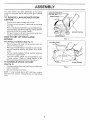
HOW TO SET UP YOUR LAWN
MOWER
TO UNFOLD
•
o
"
,
•
F_G. t
(See Fig. 1)
CATCHER
FRAME
Raise handles until lower handle section locks into
place in mowing position.
Raise upper handle section into place on lower handle,
remove protective padding and tighten both handle
knobs,
Remove handle padding holding operator presence
control bar to upper handle.
Your lawn mower handle can be adjusted for your
mowing comfort,
Refer to "Adjust Handle" in the
Service and Adjustment section of this manual.
TO ASSEMBLE
(See Fig. 2)
•
HANDLE
POSITION
GRASS
CATCHER
FRAME OPENING
Put grass catcher frame into grass bag with stiff part of
bag on the bottom.
Slip vinyl bindings over frame.
FIG. 2
NOTE: if vinyl bindings are too stiff, hold them in warm
water for a few minutes, tf bag gets wet, let it dry before
using.
6
OPERATION
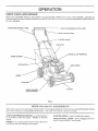
KNOW YOUR LAWN MOWER
READ THIS OWNER'S MANUAL AND SAFETY RULES BEFORE OPERATING YOUR LJkWN MOWER. Compare the
illustrations with your lawn mowerto familiarize yourself with the location of various controls and adjustments. Save this manual
for future reference,
ENGINE ZONE CONTROL
CABLE
OPERATOR
PRESENCE
DR_VE CONTROL
CONTROL
BAR
LEVER
STARTER HANDLE
CABLE
CLiP
ENGINE OtL CAP W!DIPSTICK
GRASS CATCHER
GASOLINE
CAP
PRIMER
AiR FILTER
HOUSING
WHEEL ADJUSTER
(ON EACH WHEEL)
F_G. 3
MEETS
CPSC SAFETY
REQUIREMENTS
Sears rotary waIkobehind power lawn mowers conform to the safety standards of the American National Standards Institute
and the U.S, Consumer Product Safety Commission, The btade turns when the engine is running,
OPERATOR PRESENCE CONTROL omust be held down
to the handle to start the engine. Release to stop the
engine,
STARTER HANDLE
- used for starting the engine.
DRIVE CONTROL LEVER o used to engage power-propeIIed forward motion of lawn mower.
PRIMER, pumps additional fuel from the ca[buretor to the
cylinder for use when starting a cold engine,
7
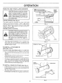
OPERATION
HOW TO USE YOUR LAWN MOWER
ENGINE
CAUTION; Do not run your Iawn mower
without mulcher plate in place and door
clipping deflector or grasscatcher
in
latch in locked position or approved
place.
Never attempt to operate the
tawn mower withthe rear door removed
or propped open.
ENGINE
SPEED
(See Fig. 4)
The engine speed is controlled
by a lever (red knob)
located on the side of the engine. "HIGH" (,1_)position
is for starting the engine, normal cutting, and better grass
bagging. "LOW" (_)
position is for light cutting, trimming and fuel economy.
ENGINE ZONE
FIG, 4
CONTROL
CAUTION: Federal regulations require
an engine control to b8 instalted on this
risk of blade contact injury. Do not unJawn mower in order to minimize the
der any circumstances
attempt to defeat the function of the operator control°
The blade turns when the engine is
running.
Your lawn mower is equipped with an operator presence control bar which requires the operator to be
positioned behind the lawn mower handle to start and
operate the lawn mower.
TO iNSTALL
FORIVIED UP TABS _
ATTACHMENTS
(See Figs. 5 & 6)
Your lawn mower was shipped ready to be used as a
mulcher, To insta!t attachments for bagging or discharging:
o Rotate rear door latch clockwise to allow rear door to be
opened.
, Open rear door, remove mulcher plate and rotate Iatch
counterclockwise to _ts original position,
o You can now insta!! catcher or optional clipping deflector.
,
To return to mulching operation reverse the above
steps. BE SURE MULCHER PLATE IS iNSTALLED
AND LATCH iS IN LOCKED POSITION BEFORE
USING FOR MULCHING OPERATION,
NULCHER
PL,ATE
F_G, 6
BRACKET
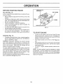
TO _NSTALL
•
•
GRASS
CATCHER
/
/b'_'_
(See Fig, 7)
Lift the rear door on the lawn mower housing and ptace
the grass catcher frame onto the formed up tabs on the
rear door hinge bracket.
The grass catcher is secured to the Iawn mower when
the rear door is lowered onto the grass catcher frame.
-..,.
GRASS CATCHER
8
FRAME
F_Go7
REAR DOOR
OPERATIO
TO EMPTY
°
°
•
GRASS
CATCHER
(See Fig. 8)
To remove grass catcher, release operator presence
control bar to stop engine.
Lift up rear door and remove the grass catcher by the
handle.
Do not drag the bag when emptying;
unnecessary wear.
DRIVE CONTROL
it wilt cause
(See Fig. 9)
o
Self-propelling is controlled by holding the operator
presence control bar down to the handle and pushing
the drive control lever forward until it clicks; then
release the lever.
•
Forward motion will stop when the operator presence
control bar is released. To stop forward motion without
stopping engine, release the operator presence control
bar slightly until the drive control disengages.
Hold
operator presence controt bar down to handle to continue mowing without self-propelling.
To keep drive control engaged when turning corners,
push down on handle and lift front wheels off ground
while turning lawn mower.
-
TO ADJUST
•
•
,
CUTTING
HEIGHT
FiG. 8
OPERATOR PRESENCE
CONTROLBAR
(See Fig. 10)
Raise wheels for tow cut and lower wheels for hig h cut.
Wheets are set in low cut for shipping. Adjust cutting
height to suit your requirements. Medium position is
best for most lawns.
To change cutting height, squeeze adjuster lever toward wheel. Move wheel up or down to suit your
requirements.
Be sure at! wheels are in the same
setting.
LOWER WHEELS
FOR HiGH CUT
RAtS E WHEELS
FOR LOW CUT
F_G. I 0
9
OPERATIO
BEFORE
STARTING
ENGINE OIL CAP
W/DIPSTICK
ENGmNE
\
OIL (See Fig. 11)
A 20 oz. bottle of Pennzoit SAE 30 oil is included with your
new lawn mower.
•
o
•
•
•
°
,
Remove engine oil cap and fii! to the FULL line on the
dipstick.
Use 20 ozs. of SAE 30 oil. SAE 10W30 oil can atso be
used. All oil must meet API service classification SG.
DO NOT use SAE 10W 40 oil.
POUR OIL SLOWLY. DO NOT OVERFILL.
Check oil level before each use. Add oil if needed. Fill
to FULL line on dipstick.
To read proper level, tighten engine oil cap each time.
Reinstall engine oil cap and tighten.
After the first two (2) hours of mowing, change the oil,
and every 25 hours thereafter.
You may need to
change the oil more often under dusty, dirty conditions.
PRIMER
GASOLINE
FILLER CAP
FEG. 11
TO START ENGINE
"
To start a cold engine, push primer three (3) times
beforetrying to start. Use afirm push_ This step is not
usually necessary when starting an engine which has
already run for a few minutes.
,
Push engine speed control lever to HIGH (,_)
tion.
.
Hold operator presence control bar down to the handle
and pull starter handle quickly. DO NOT allow starter
rope to snap back.
To "STOP" engine, release operator presence control bar.
GAS (See Fig. 11)
,
AIR CLEANER
Fitl gasoline tank with fresh, clean unleaded gasoline.
DO NOT USE PREMIUM GASOLINE. BE CAREFUL
NOT TO OVERFILL TANK.
WARNING: Experience indicates that alcohol blended
fuels (ca!led gasohol or using ethanol or methanol) can
attract moisture which Ieads to separation and formation of
acids during storage. Acidic gas can damage the fuel
system of an engine while in storage.
To avoid engine problems, the fuel system should be
emptied before storage for 30 days or longer. Drain the gas
tank, start the engine and let it run until the fuel lines and
carburetor are empty. Use fresh fuel next season. See
Storage instructions for additional information.
Never use engine or carburetor cleaner products in the fuel
tank or permanent damage may occur.
=
posi-
NOTE: In cooler weather it may be necessary to repeat
priming Steps. tn warmer weather over priming may cause
flooding and engine will not start. If you do flood engine,
wait a few minutes before attempting to start and DO NOT
repeat priming steps.
t0
OPE
0
MOWRNG TiPS
,
Under certain conditions, such as very tall grass, it
may be necessary to raise the height of cut to reduce
pushing effort and to keep from overloading the engine and leaving clumps of grass clippings.
o
For extremely heavy cutting, reduce the width of cut
and raise the rear of the lawn mower housing one (1)
wheel adjuster setting higher than the front for better
discharge of grass.
o
For better grass bagging and most cutting conditions,
the engine speed should be set in the '"HIGH" ('€_)
(FAST) position.
When using a rear discharge lawn mower in moist,
heavy grass, clumps of cut grass may not enter the
grass catcher. Reduce ground speed (pushing speed)
and/or run the lawn mower over the area a second
time.
o
•
,
,
FiG. 12
If a trail of grass clippings is left on the right side of a
rear discharge lawn mower, mow in a clockwise
direction with a small overlap to collect the clippings
on the next pass.
Keep top of engine around starter clear and clean of
grass clippings and chaff. This will help engine air
flow and extend engine life.
Pores in cloth grass catchers can become filled with
dirt and dust with use and catchers will collect less
grass. To prevent this, regularly hose catchers off
with water and let dry before using.
MULCHING
MOWING
•
Avoid cutting your lawn when it is wet. Wet grass
tends to form clumps and interferes with the mulching
action. The best time to mow your lawn is the early
afternoon. At this time the grass has dried and the
newly cut area will not be exposed to the direct sun.
o
For best resuI[s, adjust the lawn mower cutting height
so that the lawn mover cuts off only the top one-third
of the grass blades (See Fig. t2).
If the Iawn is
overgrown itwi!l be necessary to raise the height of cut
to reduce pushing effort and to keep from overloading
the engine and leaving clumps of mulched grass. For
extremely heavy mulching, reduce your width of cut,
mow slowly and raise the rear of the lawn mower one
wheel adjuster setting higher than the front.
Certain types of grass and grass conditions may
require that an area be mulched a second time to
completely hide the clippings. When doing a second
cut, mow across or perpendicular to the first cut path.
TIPS
tMPORTANT:
FOR BEST PERFORMANCE,
KEEP
MOWER HOUSING FREE OF BUILT-UP GRASS AND
TRASH. CLEAN AFTER EACH USE. SEE "CLEANING"
IN MAINTENANCE SECTION OF THIS MANUAL.
,
o The special mulching blade will recut the grass clippings many times and reduce them in size so that as
they fall onto the lawn they will disperse into the grass
and not be noticed. Also, the mulched grass wilt
biodegrade quickly to provide nutrients for the lawn.
Always mulch with your highest engine (blade) speed
as this wilt provide the best recutting action of the
blades.
,
11
Change your cutting pattern from week to week. Mow
north to south one week then change to east to west
the next week. This will help prevent matting and
graining of the lawn.
MAINTENANCE
MAINTENANCE
SCHEDULE
FtLL iN DATES
AS YOU COMPLETE
REGULAR SERVICE
SERVICE
DATES
Check for Loose Fasteners
Cleanifnspect
Grass Catcher
Clean Lawn Mower
Inspect Mower Blade
Replace/Sharpen
Mower Blade
Lubricate Pivot Points
Check Engine Oil Level
Change Engine Oil
Inspect Muffler
Replace Spark Plug
Replace Air Filter Paper Cartridge
I - Change more often when operating under a heavy Load or in high ambient temperatures,
2 - Service more often when operating in dirty or dusty conditions,
3- Rep,ace b,ades more often when mow,no in sandy soil
GENERAL
LU
B
R
N
C
HA
R
T
1
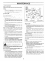
Some adjustments will need to be made periodically to
properly maintain your unit.
All adjustments in the Service and Adjustments section of
this manual should be checked at least once each season.
o
O
WHEEL
ADJUSTER
RECOMMENDATIONS
The warranty on this lawn mower does not cover items that
have been subjected to operator abuse or negligence, To
recieve full value from the warranty, operator must maintain
mower as instructed in this manual.
•
_ CAT_
Once a year, replace the spark plug, clean or replace
air filter e leme nt and check blade for wear. A new spark
p!ug and clean/new air filter element assures proper
air-fuel mixture and helps your engine run better and
last longer.
Follow the maintenance schedule in this manual.
(_HANDLEBRACKET
MOUNTING PiN
(_REARDOOR
H_NGE
BEFORE
o
o
EACH USE
Check engine oil leveE.
Check for loose fasteners,
SPRAY LUBRICANT
(_ SAE 30 OR 10W30 _iOTOR OIL. REFER TO ENGINE MAINTENANCE
SECTION,
LU BRICATION
IMPORTANT:
DO NOT OIL OR GREASE PLASTIC WHEEL
BEARINGS.
VISCOUS
LUBRICANTS
WILL ATTRACT
DUST AND DIRT THAT WILL SHORTEN THE LIFE OF
THE SELF LUBRICATING
BEARINGS. JFYOU FEELTHEY
MUST BE LUBRICATED,
USE ONLY A DRY, POWDERED
GRAPHITE
TYPE LUBRICANT
SPARINGLY.
Keep unit welt lubricated (See "LUBRICATION CHART").
12
A CE
AINTE
LAWN MOWER
CRANKSHAFT &
BLADE
ADAPTER
DETAIL
BLADE
Always observe safety rules when performing any mainteRanGe.
TIRES
,
Keep tires free of gasoline, oil, or insect control chemicals which can harm rubber.
ADAPTER
-
Avoid stumps, stones, deep ruts, sharp objects and
other hazards that may cause tire damage.
BLADE
CARE
KEY
For best results, mower blade must be kept sharp. Replace
bent or damaged blades.
TO REMOVE BLADE (See Fig. 13)
•
Turn lawn mower on its side. Make sure air filter and
carburetor are up.
•
Use a wood block between blade and mower housing
to prevent blade from turning when removing blade
bolt.
o
o
o
_i
CRANK. BOLT
SHAFT
KEYWAY
GEAR
,
(See Fig. 13)
•
Position the blade adapter on the engine crankshaft.
Be sure key in adapter and keyway in crankshaft are
aligned.
•
Position blade on the blade adapter aligning the two (2)
holes in the blade with the raised lugs on the adapter.
•
Be sure the word TOP (stamped on the blade) is toward
the engine.
,
install the blade bolt with the lock washer and hardened
washer into blade adapter and crankshaft.
,
Use block of wood between blade and lawn mower
housing and tighten the blade bolt, turning clockwise.
•
The recommended tightening torque is 35-40 ft. lbs.
IMPORTANT: BLADE BOLT IS GRADE 8 HEATTREATED.
o
CASE
The gear case is fiiled with lubricant to the proper levei
at the factory. The only time the lubricant needs
attention is if service has been performed on the gear
case.
If lubricant is required, use only Texaco Starpfex Premium Grease, part no. 750355. Do not substitute.
Check front drive wheels each time before you mow to be
sure they move freely.
The wheels not turning freely means trash, grass cuttings,
etc. are in the drive wheel area and must be cleaned to free
drive wheels.
tf necessary to clean the drive wheels, check both front
wheels.
o
•
•
blade to get the
NOTE: We do not recommend sharpening
you do, be sure the blade is balanced.
\
BLADE ADAPTER
DRIVE WHEELS
A loose blade can be dan-
Use only Sears authorized replacement
best cutting results.
LOCK WASHER
To keep your drive system working properly, the gear
case and area around the drive should be kept clean
and free of trash build-up. Clean under the drive cover
twice a season.
NOTE'. Remove the blade adapter and check the key
inside hub of blade adapter. The key must be in good
condition to work properly. Replace adapter if damaged.
CAUTION:
gerous,
[_
FIG, 13
Protect your hands with gloves and/or wrap blade with
heavy cloth,
Remove blade bolt by turning counter-clockwise.
Use
a 9/16" box or open-end wrench.
Remove blade and attaching hardware (bolt, lock
washer and hardened washer).
TO REPLACE BLADE
SHAFT
__ CRANK-
BLADE
Remove hubcaps, hairpin cotters and washers.
Remove wheels from wheel adjusters.
Remove any trash or grass cuttings from inside the
dust cover, pinion and/or drive wheel gear teeth.
Put wheels back in place.
if after Cleaning, the drive wheels do not turn freely,
contact your nearest Sears Service Center.
GRASS
blade - but if
•
TO SHARPEN BLADE
o
The blade can be sharpened with afite or on a grinding
wheel. Do not attempt to sharpen while on the mower.
To check blade balance, drive a nail into a beam or walt.
Leave about one inch of the straight nail exposed.
Place center hole of blade over the head of the nail, tf
blade is balanced, it should remain in a horizontal
position, If either end of the blade moves downward,
sharpen the heavy end until the blade is balanced.
13
CATCHER
The grass catcher may be hosed with water, but must
be dry when used.
Check your grass catcher often for damage or deterio_
ration. Through normal use it will wear. If catcher
needs replacing, replace only with a manufacturer
approved replacement catcher from Sears. Give the
lawn mower model number when ordering.
MAINTENANCE
ENGINE
LUBRICATION
Change the oil after the first two hours of operation and
every 25 hours thereafter or at least once a year if the lawn
mower is not used for 25 hours in one year.
Check the crankcase oil level before starting the engine
and after each five (5) hours of continuous use. Add SAE
30 motor oil or equivalent. Tighten oil plug securely each
time you check the oil level.
ONTAtNER
TO CHANGE ENGINE OIL (See Fig, 14)
.
•
.
o
.
Remove engine oil cap; lay aside on a ciean surface.
Tip Sawnmower on its side and drain oil into a suitable
container. Rock lawn mower back and forth to remove
any oil trapped inside of engine.
Wipe off any spilled oil on lawn mower and on side of
engine.
Fitt engine with SAE 30 or t0W 30 oil. All oil must meet
API service classification SG. Fill only to the "FULL"
line on the dipstick. DO NOT OVERFILL.
Replace engine oil cap.
Reconnect spark plug wire to spark plug.
FIG, 14
BACK PLATE
CARTRIDGE
t
LiP
\
AIR FILTER
TABS
Your engine wi!! not run properly and may be damaged by
using a dirty air filter.
Replace the air filter every year, more often if you mow in
very dusty, dirty conditions. Do not wash air filter.
SCREW
FiG, 15
TO SERVICE AIR FILTER (See Fig. t5)
.
Loosen screw and tilt cover as shown.
o
•
°
CLEANING
Carefully remove cartridge.
Clean by tapping gently on a flat surface. If very dirty,
replace cartridge or clean as follows:
Wash in a low or non-sudsing detergent and warm
water solution. Rinse thoroughly with flowing water
from mesh side until water runs clear. Let cartridge air
dry thoroughly before using.
CAUTION:
Petroleum
solvents,
COVER
IMPORTANT:
FOR BEST
PERFORMANCE,
KEEP
MOWER HOUSING
FREE OF BUtLT-UP
GRASS AND
TRASH.
CLEAN UNDERSIDE
OF MOWER HOUSING
AFTER EACH USE,
CAUTION: Disconnect spark plug wire
from spark plug and p_ace wire where it
cannot come in contact with the spark
plug,
such
cartridge,
They may cause deterioraas kerosene,
are not to be
tion
of the cartridge.
Doused
not to
oilciean
cartridge,
Do not use pressurized air to
clean or dry cartridge.
Install cartridge, then replace cover making sure the
tabs are aligned with the slots in back plate. Fasten
screw securely.
•
Turn lawn mower on its side.Make sure air filter and
carburetor are up, Clean the underside of your lawn
mower by scraping to remove build-up of grass and
trash,
•
Clean engine often to keep trash from accumulating, A
clogged engine runs hotter and shortens engine tife,
Keep finished surfaces and wheels free of al! gasoline,
oi!,etc.
We DO NOT recommend using a garden hose to clean
lawn mower unless the electrical system, muffler, air
filter and carburetor are covered to keep water out.
Water in engine can result is shortening engine life,
.
MUFFLER
.
Inspect and replace corroded muffler as it could create a
fire hazard and/or damage.
SPARK PLUG
CLEAN
Change your spark plug each year to make your engine
start easier and run better. Set spark plug gap at .030 inch.
UNDER
DRWE COVER
Clean under drive cover at least twice a season, Scrape
underside of cover with putty knife or similar tool to remove
any build-up of trash or grass on underside of drive cover,
14
SERVICE AND ADJUSTIVl
CAUTtON:
TS
BEFORE PERFORMING ANY SERVICE OR ADJUSTMENTS:
••
Releasecontrol
bar, and atl moving
Make sure the btade
o
Disconnect spark plug wire from spark plug and place where it cannot come in contact
parts have completely stopped.
with plug.
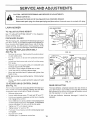
LAWN MOWER
TO ADJUST
CUTTING
See "TO ADJUST CUTTING
section of this manual.
DISCHARGE
HEIGHT
HEIGHT" in the Operation
GUARD
ROTATE
The discharge guard, attached to the discharge opening of
your lawn mower, is provided to prevent the possibility of
injury resulting from objects being thrown out of the discharge opening into the operator mowing position. If the
discharge guard becomes damaged, it should be replaced.
TO REMOVE/REPLACE
(See Fig. t6)
o
o
o
o
o
•
BELT
PRESS
DRIVE BELT
F_G. 16
Remove ddve cover, Remove belt by pushing down
on gear case pulley.
Turn lawn mower on its side with carburetor and fuel
cap up.
Loose9 hex h'ead screw and move belt snub'ber away
from pulley.
Remove be_t from engine pulley on crankshaft and
carefully stip be{t off over blade.
CAUTION: Sharp edges of blade can cut belt,
Install new belt by reversing above steps.
Move belt snubber back in place and tighten hex
head screw.
DRIVE
Always use factory approved
long life.
TO ADJUST
_
CLUTCH
SPRING
y_
CLAMP
.CABLE
__P_"
__
SHtFTER_,)
NOTE: Belt snubber clears belt by approx. 1/32 inch when
installed.
o
PLIERS
JAM NUT "C"-JAM NUT "B":
_SLEEVE
f tif
SCREW"A"
t
ADJUSTING
BRACKET
belt to assure fit and
DRIVE CONTROL
FiG. t7
CABLE
(See Fig. 17)
REAR
A drive control cabIe that needs adjustment will keep your
_awn mower from self-propelling properly and can also
cause gear case components to wear out sooner.
,
Remove drive cover.
The rear deflector, attached between the rear wheels of
your lawn mower, is provided to minimize the possibility
that objects will be thrown out the rear of the lawn mower
into the operator's mowing position.
o
•
If the rear deflector
replaced.
o
o
o
o
°
o
Loosen cable clamp screw "A" and nuts "B" and "C".
Hold down operator presence controt bar to handle
and engage drive control.
Move shifter arm to drive position while rotating front
wheelsto besurejaw ctutci_ is engaged. Pullthreaded
sleeve with pliers. Do not putl on control cable.
Tighten nut "C" untiI sleeve is snug,
Tighten screw "A" and nut "B".
Push lawn mower back and forth to be sure gear case
is engaged.
Rev_ace drive cover.
Release opeLtor prese_ce control bar.
15
DEFLECTOR
becomes
damaged,
it should
be
ENGlNE
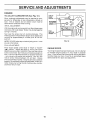
TO ADJUST
CARBURETOR
TOP NO
LOAD
SCREW
(See Fig. 18 )
Minor carburetor adjustments may be required to compensate for differences in fuel, temperature, altitude or
toa.d. The air cleaner and air cleaner cover must be
assembled to carburetor when running.
IDLE SPEED
ADJUSTING
SCREW
INITIAL ADJUSTMENTWith the engine not running, gently turn idle mixture screw
clockwise until it just closes. Screw may be damaged by
turning it in too far.
IDLE
MIXTURE
Next open the screw one turn counter-clockwise.
This
initial adjustment will permit the engine to be started and
warmed up (approximately 5 minutes) prior to final adjustment.
FIG. 18
NOTE: DO NOT adjust top no load adjusting screw. It was
pre-set at the factory,
FINAL ADJUSTMENTPlace engine speed control lever in "IDLE" or "SLOW"
(,g_) position. Adjust idle RPM by turning idle speed
adjusting screw to obtain 1400 RPM. Next, turn idle mixture
screw in (clockwise- lean mixture) until engine just starts to
slow. Then turn idle mixture screw out (counter-clockwise
- rich mixture) until engine runs unevenly. Now turn idle
mi_ure screw midway between rich and lean. Engine
should accelerate smoothly. If engine does not accelerate
properly, the carburetor should be readjusted, usually to a
richer mixture, by turning the idle mixture screw counterclockwise 1/8 turn more.
ENGINE
SPEED
Your engine speed has been factory set. Do not attempt
to increase engine speed or it may result in personal
injury. If you believe that the engine is running too fast or
too slow, take your lawn mower to an authorized Sears
Service Center for repair and adjustment.
16
SERVICE AND ADJUSTMENTS
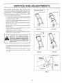
TO ADJUST
HANDLE
(See Figs.
lg Thru 21)
SHIPPING POSITION
Your lawn mower handle can be raised or lowered for your
mowing comfort. Four (4) positions are available: high,
medium high, medium low and low. Handles are shipped
mounted in the medium low position.
•
•
•
•
•
o
o
•
MEDIUM LOW
To change from medium low to medium hugh position,
the upper and lower handle sections will have to be
turned over (See Fig. 19B).
Remove the controls and operator presence control
bar from the upper handle.
Remove the starter rope guide from the lower handle.
Remove hairpin cotters.
Disconnect the lower handle from the handle brackets
(See Fig. 2t).
Turn the handle over and reassemble the hairpin
cotters that have been removed.
FIGo 19B
FiG. 19A
Reassemble the starter rope guide.
Reassemble the controls and the operator presence
control bar to the upper handle.
LOW
CAUTION:
The operator
presence
control bar must pivot freely to permit
blade brake engagement when control
bar is released. Do not overtighten the
fasteners hotding the controls to the
upper handle.
•
o
To change from med;um
upper handle section will
Fig. 20A).
To change from medium
lower handle section wiii
Fig. 20B).
HIGH
low to high position only the
have to be turned over (See
low to low position, only the
have to be turned over (See
FIG. 20A
FIG. 20B
HAN DLE
BRACKET
HAIRPIN
CLIP
FIG. 21
17
STORAGE
....
,,, ,',ran,,,
,,
ENGINE
Immediately prepare your lawn mower for storage at the
end of the season or if the unit will not be used for 30 days
or more.
FUEL SYSTEM
IMPORTANT:
IT _S IMPORTANT TO PREVENT GUM
DEPOSITS FROM FORMING IN ESSENTIAL FUEL
SYSTEM PARTS SUCH AS CARBURETOR, FUEL FILTER,
FUEL HOSE, OR TANK DURING STORAGE.
ALSO,
EXPERIENCE INDICATES THAT ALCOHOL. BLENDED
FUELS (CALLED GASOHOL OR USING ETHANOL OR
METHANOL) CAN ATTRACT MOISTURE WHICH LEADS
TO SEPARATION AND FORMATION OF AC!DS DURING
STORAGE.
ACIDIC GAS CAN DAMAGE THE FUEL
SYSTEM OF AN ENGINE WHILE !N STORAGE.
LAWN MOWER
When lawn mower is to be stored for a period of time, clean
it ttioroughly, remove all dirt, grease, leaves, etc. Give
blade and underside of housing a good coat of grease or
rust preventative, Store in a c!ean, dry area.
o CIean entire lawn mower (See "CLEANING" in the
Maintenance section of this manual),
o Lubricate as shown in the Maintenance section of this
manual.
o
o
Be sure that all nuts, bolts, screws, and pins are
securetyfastened.
Inspect moving partsfor damage,
breakage and wear, Replace if necessary,
Touch up all rusted or chipped paint surfaces; sand
lightly before painting.
HANDLE
,,'
.
Drain the fuel tank.
.
Start the engine and let it run until the fuel Iines and
carburetor are empty.
.
Never use engine or carburetor cIeaner products in the
fuel tank or permanent damage may occur_
Use fresh fuel next season,
•
NOTE:
Fuel stabilizer is an acceptable alternative in
minimizing the formation of fuel gum deposits during storage, Add stabilizer to gasoline in fuel tank or storage
container, AIways follow the mix ratio found on stabitizer
container. Run engine at least t0 minutes after adding
stabilizer to allow the stabilizer to reach the carburetor, Do
not drain the gas tank and carburetor if using fuel stabiiizer.
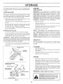
(See Fig. 22)
You can fold your lawn mower handle for storage.
o
To fold, squeeze the bottom ends of the lower handle
toward each other until the lower handle clears the
handle bracket, then move handle forward,
IMPORTANT:
WHEN FOLDING THE HANDLE FOR
STORAGE OR TRANSPORTATION, BE SURE TO FOLD
THE HANDLE AS SHOWN IN FIG. 22. IF YOU FOLD THE
UPPER HANDLE SECTION THE WRONG WAY, YOU
MAY DAMAGE THE CONTROL CABLES.
ENGINE
OIL
Drain oil (with engine warm) and re___e
_'_" with ctean engine
oi!. (See "ENGINE" in the Maintenance section of this
manual).
.... _.... j,_ ..... :.......... .,,
position,
the Lower he.ndie will automaticatIy lock into the mowing position,
CYLINDER
LOWER HANDLE
HANDLE
BRACKET
.
Remove spark plug.
.
Pour one ounce (29 ml) of oil through spark ptug hole
into cylinder.
o
Pull starter handle slowly a few times to distribute oi!.
.
Replace with new spark plug.
OTHER
HAiRPiN
COTTER
OPERATOR PRESENCE
CONTROLBAR
•
Do not store gasoline from one season to another.
•
Replace your gasoline can if your can starts to rust.
Rust and/or dirt in your gasoline will cause problems.
•
If possible, store your unit indoors and cover it to give
protection from dust and dirt.
.
Cover your unit with a suitabIe protective cover that
does not retain moisture, Do not use plastic. Plastic
cannot breathe which aI!ows condensation to form and
will cause your unit to rust.
IMPORTANT: NEVER COVER MOWER WHILE ENGINE
AND EXHAUST AREAS ARE STILL WARM.
UPPER HANDLE
FOLD FORWARD
FOR STORAGE
FOLD BACKWARD
MOWING
POSiT|ON
CAUTION,' Never store the lawn mower
with gasoline in the tank inside a bui!ding where fumes may reach an open
flame or spark, Allowthe engineto coo_
before storing in any encfosureo
LOWER HANDLE
FiG. 22
18
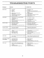
TROUBLES
O0
G POI TS
PROBLEM
CAUSE
CORRECTION
Does not start
1.
2+
3,
4.
Dirtyair filter.
Out of fuel+
State fuel.
Water in fuel.
t,
2.
3.
4+
Clean/replace air fitter.
Fill fueitank,
Drain tank and refill with fresh clean fuel.
Drain fuel tank and carburetorand refi_l tank with fresh
5,
6.
7.
8,
9,
Spark plug wire is disconnected.
Bad spark ptug,
Loose btade or broken bIade adapter.
Control bar in released position
Control bar defective
5,
6.
7+
8,
9.
gasoline,
Connect wireto plug,
Replace sparkplug.
Tighten b+ade bo+t or replace blade adapter.
Depress control bar to handle+
Replace contro+ bar.
t.
1,
Set in "Higher Cut" position,
2.
3,
4.
5.
6,
Rear of +awn mower housing/blade dragging
in heavy grass.
Cutting too much grass,
Dirtyair fiker,
Buildup of grass, leaves and trash under mower.
Too much oil in engine.
Walking speedtoo fast.
2.
3+
4,
5+
6.
Set in"Higher Cut" position.
Clean/replace air filter,
CIean underside of mower housing.
Check oil level,
Cut at slower wa!king speed.
Poor cut - uneven
1,
2.
3.
4.
Worn, bent or loose blade.
Wheel heights uneven.
Low engine speed.
Buildup of grass, leaves, and trash under mower,
1,
2.
3,
4+
Replace blade+ Tighten blade bolt.
Set a+lwheeIs at same height.
Set engine speed control in H}GH posit+on+
Clean underside of mower housing.
Excessive
1+
2+
Worn, bent or loose blade.
Bent engine crankshaft.
t,
2.
Replace blade. Tighten blade bott.
Contact Sears Service Department.
t.
t.
2,
3.
4.
Engine flywhee+ bra_<eis on when control bar is
released.
Bent engine crankshaft
Blade adapter broken.
Blade dragging in grass.
Depress control bar to upper handle before
puiting starter rope.
Contact Sears Service Department.
Replace blade adapter.
Move {awn mower to cut grass or to hard surface
to start engine,
Loss of drive
t.
2.
Drive wheeis not turning with drive control engaged.
Belt not driving,
1.
2+
Adjust or rep}ace drive control cable, if broken.
Put belt on pulleys or replace belts if broken.
Grass catcher not filling
(if so equipped)
1.
2.
Cutting height too low.
Lift on bIade worn off+
t.
2.
Raise cutting height.
Replace blade.
3+
4.
Catcher not venting air.
Lowengine speed,
3.
4.
Clean grass catcher.
Set engine speed control in HIGH position,
t.
2.
t,
2.
3.
Grass is too high or wheel height is too low.
Rear of lawn mower housingibtade dragging
in grass,
Grass catcher too full.
4.
Handle height position not right for you+
Raise
Raise
setting
Empty
Adjust
Loss of power
vibration
Starter rope hard to pui|
Hard to push
19
2.
3.
4.
3.
4.
cutting height.
rear of lawn mower housing one (1)
higher.
grass catcher.
handle height to suit.
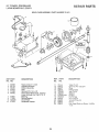
CRAFTSMAN
REPAIR PARTS
22" ROTARY LAWN MOWER MODEL NUMBER 917.372471
1
\
27
\
O
44
38
_
\
33
24
#
30
54
62
%
CRAFTSMAN
22" ROTARY LAWN MOWER MODEL NUMBER
KEY PART
NO. NO
DESCRiPTiON
KEY PART
NO. NO
DESCR|PT_ON
1
2
3
4
5
8
7
8
9
t0
11
12
13
14
15
t8
t7
!8
19
20
21
22
23
24
25
28
27
28
28
30
31
32
33
34
Upper Handte
Engine Zone Controf Cable
Hex Head Bolt !/4-20x 1-1/2
Locknut 1/4-20
Cable Clip
Handle Knob
Locknut !/4-20
Control Bar
Rear Door Kit (Incl. Key #t0)
Hinge Rod
Self Tapping Screw #t0_24
Hex Tapping Screw 1/4-20 x t/2
Hex Head Screw 1/4=20 x 1/2
Back Plate
Side Baffle
Discharge Baffle
Rear Baffle
Truss Head Screw #10-24 x 1/2
Locknut #10-24
Rear Skirt
Muncher Plate
Engine Pulley
Hi-Pro Key #505
Hubcap
Retainer Clip
Washer
Whee_ & Tire Assembly
Shoulder Bolt 3/8-16
Belleville Washer
Axle Arm Assembly
Selector Knob
Selector Spring
Washer
Spacer
Wheel Adjusting Bracket (Left)
Wheel Adjusting Bracket (Right)
37
38
39
40
41
42
43
44
45
46
47
48
49
50
51
52
53
54
55
56
57
58
59
60
61
62
64
55187
STD541431
869!2X4t7
86913X417
850998
7500£7
87930
48173
13087tX004
851514
752234
851074
850263
85!084
87587X479
85463
851000
STD533107
751592
88652
5t793
84678X479
58714
85!201X004
103672X
132231
t32133
65
-o
130577
13208!
Thread Cutting Screw 5/16-18 x 3/4
Locknut 5/16o18
Handle Bracket Assembly (Left)
Handle Bracket Assembly (Right)
Hex Head Thread Rolling Screw 3/8q 6 x lq/8
Hex Washer Head Screw #10-24 x t/2
Guide Clip
Lawn Mower Housing (Incl, Key #14,15,51 &52)
Door Latch
Blade Adapter
Blade 22"
Hardened Washer
Hetical Washer 3/8-24 x 1-3/8 Grd. 8
Hex Head Machine Screw 3/8-24 x !-3/8 Grd. 8
Front Baffle
Danger Decal
BeltSnubber
Carriage Bolt 5/16-18 x 5/8
Locknut 3/8-t6
Hinge Screw
Hairpin Cotter
Lower Handle
Handle Bolt
Washer
Rope Guide
Debris Shield
Engine _ Briggs & Stratton Model No, 124702 =Type
3186o0t
Screw 1/4o20 Hex Tapping
Owner's Manual
35
38
850991X479
130861
STD522515
STD54t425
85827
63688
STD541425
851509
48137
750328
36953
STD5t2505
54583
88844X479
750480X479
88668X479
87596X479
STD511005
STD541410
t28796
t30795X479
84596
87677
77400
85!79
52160
87748
84921
62335
85021X004
87877
850855X004
88348
84920
850923
850924
9!7,372471
REPAIR
Available accessories not included with lawn mower:
Z.!_33303
Clipping Deflector
Z_!_33623
Gas Can (2.5 geL)
7133500
Fuel Stabilizer
7_1 33300
SAE 30W Oi_ (20 oz.)
PARTS
CRAFTSMAN 22" ROTARY LAWN MOWER MODEL NUMBER 917°372471
54
14
7
\
23
24
REPAIR PARTS
CRAFTSMAN
KEY
NO.
1
2
3
4
5
6
7
8
9
10
11
12
13
14
t5
!6
17
18
19
20
2!
22
23
PART
NO,
48029
128776
74189
750029
83691
54338
85179
77400
52160
86960
87729
12000003
74507
76401
86273
86274
851019X004
87877
88284X004
850992
58922
74100412
85t021X004
22" ROTARY LAWN MOWER MODEL NUMBER 917,372471
DESCRIPTION
Drive Head Kit
Drive Control i,t4C,c,}_"_ (_0-_
i_U:_,-m,
Locknut #10-24
Pan Head Machine Screw #t0-24 x 2
V-Belt
Hex Head Boft I/4-20 x 2-3/4
Retainer Ctip
Hubcap
Washer
Nylon Bushing
Wheet & Tire Assembly 8.00 x 2.00
E-Ring
Pinion
Dust Cover
Spacer Bearing
Belleville Washer
Selector Spring (Left)
Selector Knob
Axle Arm Assembly
Wheel Adjusting Bracket
Retaining Clip
Flat Head Machine Screw
Selector Spring (Right)
'-s ,,
KEY
NO.
24
25
26
27
28
29
PART
NO
851226
751031
87866
750097
751029
750108
30
31
32
33
34
35
36
37
38
39
40
4!
52
53
83700
74976
83681
48269
STD580014
48175
48184
83632
STD541425
57076
75192
48174
88614
.....
54
55
56
751663
86012
851552
REPAIR PARTS
DESCRIPTION
Washer
Drive Cover Decal
Pan Head Tapping Screw #10-24 x 2-3/4
Hex Washer Head Screw #10-24 x 3/4
Drive Cover
Hex Washer Head Tapping Screw
#10-24 x 3/8
Cable Clamp
Retaining Ring
Drive Pulley
Drive Control Cable Kit
Woodruff Key #3
Wheel Adjuster Assembly (Left)
Gear Case Assembly
Spring
Locknut 1/4-20
Woodruff Key #213
Spring
Wheel Adjuster Assembly (Right)
Catcher Frame
Clipping Deflector Accessory (not included with lawn
mower) 71133303
Grassbag Assembly
Ddveshaff Cover
Screw, Pan Head, Hi-Lo #!0-16 x t/2
REPAIR PARTS
22" POWER- PROPELLED
LAWN MOWER 917,372471
GEAR CASE ASSEMBLY
PART NUMBER 751001
t5
t0
p.
9
!
8
|
REF. PART
NO. NO.
t
2
3
4
5
6
53838
85178,
88386
57072
57388
48032
7
8
9
t0
77881
77039
750430
57079
DESCRIPTION
REFo PART
NO.
NO.
DESCRtPT?ON
Keps Locknut 1/4-20
Adjusting Bracket
Shifter Assembly
Seal
Grooved Pin 1/8 x 1/2
Gear Case Halves (lncl. Upper &
Lower Halves) (incl. Ref. 4, 5, 7)
Bearing
Spring Bracket
Drive Shaft
Hardened Washer
11
12
13
14
15
16
17
18
19
20
21
22
Yoke C!utch
Grooved Pin 1/8 x 3/4
Plug
Helical Gear
Jaw Clutch
Grease
E-Ring
Hi-Pro Key
Worm Shaft
Woodruff Key #3
Worm
Hex Head Machine Screw 1/4-20 x
1-1/4
24
75144
87822
86447
83659
75O436
750355
STD581050
850848
83720
65692
83680
50950
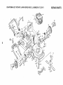
MODEL NO, 124702
TYPE NO. 3t86o0I
BRIGGS & STRATTON
4oCYCLE ENGINE
I
-2j
3
6t5
230
383
9
8
i
10
!
284
525 _
842 _
15
8
47
20
25
I
MODEL NO, 124702
TYPE NOo 3186-0!
BR_GGS & STRATTON
4°CYCLE ENGINE
968
%
969
t 24
971A
%.
!17
/
@ 634
130
(_
I27
!34
_
95
0
617
967
%
137
163
966
971
116@
I16@
_467
620
188A
%
670A
26
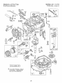
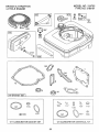
MODEL NOo ] 2:4702
TYPE NO. 3186-0!
BRIGGS & STRATTON
4-CYCLE ENGENE
1040
55
332
455
23
69 @
456
515 (_
69A
@
461
334
305
304
851
27
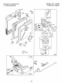
MODEL NO. 124702
TYPE NO. 3186-01
BRtGGS & STRATTON
4oCYCLE ENGINE
957
Q
949
387
353
81
!
7
9
3
358
GASKET
SET [
@
116
Q
%
2O
104
!t7
134
617
534
977 CARBURETOR
@
GASKET
t21
SET
28
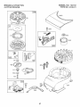
CARBURETOR
t27
116
617
634
OVERHAUL
KIT
MODEL NO. 124702
TYPE NO, 318(}-01
BRaGGS & STRATTON
4-CYCLE ENG6NE
KEY
NO.
1
2
PART
NO.
493260
293708
3
5
7
8
9
9A
10
1I
12
13
15
16
393862
213610
272200
399717
271904
272238
94222
231685
272198
94547
93418
493362
94388
493279
399781
94220
94612
t8
20
22
23
24
25
26
27
28
29
492177
222698
493262
493385
493386
4£3387
493261
493388
493389
493390
26026
298909
298908
490566
490743
32
33
34
35
40
94405
262651
262652
262224
93312
45
46
47
52
54
55
56
57
58
262204
492830
493737
272199
94526
492831
492832
262594
280399
59
60
69
69A
81
95
98
98A
104
116
117
!18
121
124
125
127
t30
t31
133
134
137
163
187
188
396892
393152
280973
224322
223664
94098
398185
493280
231371
oo--493765
493762
94525
493627
--223470
493267
398187
398188
--272296
492790
398540
188A
94644
DESCRIPTION
Cylinder Assembty
Bushing, Cy!inder (Special Tools
Required for Installation)
* Seal, Oil
Head, Cylinder
* Gasket, Cylinder Head
Breather, Valve Chamber
* Gasket, Valve Cover
* Gasket, Baffle Plate
Screw, Seres, Breather Mounting
Tube, Breather
* Gasket, Crankcase
Screw, Cylinder Head
Plug, Hex, Socket
Crankshaft,.
Timing Gear Key
Sump, Engine
* Seal, Oil
Screw, Sere, Sump Mounting
Screw, Sump Mounting (Used in Hole
Nearest Breather)
Flywheel, Magneto
Key, Flywheei
Piston Assembly, Standard
Piston Assembly .010" Oversize
Piston Assembly .020" Oversize
Piston Assembly .030" Oversize
Ring Set, Piston, Standard
Ring Set, Piston .010' Oversize
Ring Set, Piston .020" Oversize
Ring Set, Piston .030" Oversize
Lock, Piston Pin
Pin Assembly, Piston, Standard
Pin Assembly, Piston .005" oversize
Rod Assembly, Connecting
Rod Assembly, Connecting
.020" Undersize Crankpin Bearing
Screw, Connecting Rod
Valve, Exhaust
Valve, Intake
Spring, Valve
Retainer, Valve Spring (Used with
VaJves with Groove in Stem)
Tappet, Valve
Gear, Cam
Oil Slinger Gear and Bracket
* Gasket, intake Elbow
Screw, Intake Elbow Mounting
Housing, Rewind Starter
Pulley, Rewind Starter
Spring, Rewind Starter
Rope, Rewind Starter
***
*
PART
NO.
262579
262660
492349
67072
94512
945tl
490547
493293
94513
224324
94515
92284
802574
93381
492167
94581
398808
493263
19069
383
387
455
456
459
461
467
515
523
524
525
528
529
562
572
592
601
608
6t3
6t5
6t6
617
620
62t
625
634
635
670
670A
741
842
847
851
869
870
871
89838
394281
224250
224321
492833
262626
280857
262625
493950
280393
493952
399254
280943
92613
224328
231082
93807
493295
94231
94474
262578
270344
493895
396847
492717
-- 66538
DESCRIPTION
Link, Governor
Spring, Governor
Lever Assembly, Governor
Washer, Governor Crank
Screw, Hex Head
Screw, Hex Head
Muffler, Exhaust
Housing, Biower
Screw, Sems, Hex Head
Shietd, Cylinder
Screw, Hex Head
Nut, Flywheel
Armature, Magneto
Screw, Sere, Armature Mounting
PIug, Spark
Locknut
Wire, Ground
Gasket Set
Puller, Flywheel
(Optional Accessory)
Wrench, Spark PLug
Primer Assembly
Cup, Starter
Retainer, Rewind Starter
Pawl, Starter
Pin, Starter
Knob, Contro_
Spring, Torsion
Cap with Dipstick, Oil Filler
Seal, Filler Tube
Tube, Oit Filler
Hose, Primer
Grommet, Breather
Bolt, Governor Lever
Baffle, Cylinder
Nut, Hex
Clamp, Hose
Starter Assembly, Rewind
Screw, Muffler Mounting
Nut, Push (Governor Crank)
Crank, Governor
*** Seal, Fuel intake Tube
Bracket Assembly, Carburetor Control
Switch, Stop
Tube, Fuel Intake
*** Washer, Shaft (Sold in Kit OnIy)
Elbow, Spark Ptug
Spacer, Fuel Tan_(
Spacer, Carbureto, Bracket (Incl. 2)
Gear, Timing
Seal, Q-Ring
Dipstick & Tube Assembly, Oil Filbr
Terminal, _gnition Cable
Seat, Intake Valve, Standard
Seat, Exhaust Valve, Standard
Guide, Exhaust Vatve
Guide, intake Valve
922
Spring, Brake
923
Brake Assembly
949
Guard, Finger
955
Screw, Bowl Mounting
957
Cap Assembly, Fuel
966
Base, Air Cleaner
967
Filter, Air
968
Cover, Air Cleaner
969
Screw, Cover Mounting
97t
Screw, Air Cleaner
97tA
Screw, Air Cleaner (Base to Carburetor)
972
Fuel Tank Assembly, Red, 1-1/2 Quart
Capacity
975 493640
Bowt Assembly, Carburetor
977 490937
Gasket Set, Carburetor
10t6
224278
Cover, Rewind Starter
t019
494256
Label Kit
1040
281025
Trim Plate
Included in Gasket Set (493263)
included in Carburetor Overhaut Kit (493762)
Included in both Carburetor Overnaui Kit (493762)
and Carburetor Gasket Set (490937)
(Cut to 88-5/8")
**
***
**
KEY
NO.
201
209
227
230
258
284
300
304
305
306
307
332
333
334
337
353
356
358
363
Insert, Handle
Handie, Rewind Starter
Washer, Rewind Starter
Washer, Rewind Starter
Lock, Muffler Screw
Screw, Seres, Throttle Valve Mounting
Screw, Idle Adjustment
Screw Assembly, Speed Adjust
Pin, Float Hinge
Gasket, Sealing (Sold in Kit Only)
Jet (Sold in Kit Only)
Valve and Spring, Needle
Carburetor Overhaul Kit
Screw, Carburetor Mounting
Carburetor Assembly
Plug, We;ch (Sold in Kit Only)
Valve, Throttle
Sh_ft and Lever, Throttle
Float Assembly, Carburetor
Valve, Inlet dnctudes Seat)
Gasket, Bowl (Sold in Kit Only)
Gasket, Air Cleaner
Hose, Fuel
Screw, Tank Mounting (includes
Washer)
Screw, Rex Washer Head
29
NOTE:
280512
493823
262598
280966
493459
221798
2t3512
2t35t3
262001
63709
262640
493442
281136
493637
397974
492363
491588
280937
94120
94269
9412t
494354
All
component
dimensions given in U.S. inches
1 inch
= 25,4 mm
SERVICE
30
NOTES
SERVICE
31
NOTES
£RUFTXMrlN®
OWNER'S
MANUAL
5.0 HORSEPOWER
22" REAR DISCHARGE
2 in ONE Mulcher/Bagger
POWER PROPELLED
ROTARY LAWN MOWER
Each Lawn Mower has its own model number.
engine has its own model number.
MODEL NO.
917.372471
Each
The model number for your lawn mower will be found on
a decal attached to the rear of the lawn mower housing.
The model number for the engine will be found on the
Blower Housing of the engine adjacent to the spark plug.
All parts listed here in may be ordered through Sears,
Roebuck and Co. Service Centers and most Retail
Stores.
WHEN ORDERING REPAIR PARTS, ALWAYS GIVE THE
FOLLOWING INFORMATION:
• PRODUCT-
"ROTARY
LAWN MOWER"
• MODEL NUMBER - 917.372471
• ENGINE - BRIGGS & STRATTON
HOW TO ORDER
REPAIR PARTS
MODEL NO. 124702, TYPE NO. 3186-01
- PART NUMBER
• PART DESCRIPTION
Your Sears merchandise has added value when you
consider that Sears has service units nationwide
staffed with Sears trained technicians...professional
technicians _,pecifica!ty trained on Sears products,
having the parts, tools and the equipment to insure that
we meet our pledge to you, we service what we sell.
134056
IIIIIIIIII IIIIIII
9/27/91
Printed in U.S.A.
III
lIHlll
IIII
IIIIIIIIII
IIIIIIIIIIIIIIIIIII
I II IIIIII
ill lllllllllll
IIIIIIIIIIIIII
IIII
II
IIIIllllllll
ill II
IIII IIIIIIIIIIIIIIIIIIIIIII
II IIIII